OPERATORS MANUAL REACHMASTER FALCON
|
|
|
- Dortha McDonald
- 5 years ago
- Views:
Transcription
1 OPERATORS MANUAL REACHMASTER FALCON Do not use the platform without reading and following the instructions carefully. Failure to comply with the correct operating procedures and safety instruction, can cause personnel injury or death.
2 Information Congratulation with Your new Reachmaster Falcon. Based upon intensive and determined product development and deep environmental awareness, combined with national and international co-operation, it is our common goal to be able to enrich our surroundings with products and service, which represent the optimum and ultimate within: Technology Safety Environment Economy Quality Reachmaster supports all customers, national as well as international. In case of technical and/or operational questions, please contact our Service Department, Phone Toll Free Reporting errors You can help to improve and correct this document. If you find any mistakes, please let us know. Mail or your observations directly to: ReachMaster Inc. 1416D Stonehollow Drive Kingwood TX USA
3 Table of Contents Information 2 Summary of S Introduction Handling by crane Transportation in containers Remove ropes Turn main switch on Remove wooden blocks Important Supplements 14 Supplement A 15 Supplement B 16 Supplement C 23 Supplement D 23 Supplement E Electrical equipment Engaging the electrical system Choice of control Stability system Controls on the platform Charge indicator Battery capacity Indicator Basket rotator (Option) Acoustic signals Hydraulic equipment Hydraulic equipment Power transmission Activation of main boom Activating outriggers Controls of the platform Basket locked Basket levelling Operators Instructions Driving the platform Driving the platform Driving the platform Change the axle width Setting up the outriggers Setting up the outriggers Setting up the outriggers Setting up the outriggers Stowing the outriggers Before using the platform Mounting the basket Power supply Diesel engine 43
4 5.4 Operating the platform Basket Control Panel Basket Control Panel Chassis Control Panel Emergency Lowering General Electrical pump Basket levelling Emergency lowering Telescopes Emergency lowering Slewing Emergency lowering Link arm Emergency lowering Main boom Emergency lowering Basket levelling Emergency lowering Emergency lowering Slewing Emergency lowering Link arm Emergency lowering Main boom After using the platform Transporting the platform Safety Instructions Inspection and maintenance Daily inspection Weekly inspection Monthly inspection Yearly inspection Inspection and maintenance Spare parts modification Tightening of the crawler belts Tightening of the crawler belts Lubrication diagram 82 Appendix 85 Appendix A: Sliding tracks 86 Appendix B: Key switch at the turret 86 Appendix C: Outriggers with hinged joints. (Option). 88 Appendix D: Reduced working height 89 Appendix E: Twin wheels 89
5 Summary of S In this chapter you will find: Summary of essential S
6 6 Summary of S At page: 12 Do not attempt to open any boxes containing electrical components, when mains are connected to the machine. Contact with the main supply can cause injury or death. Before opening the boxes with electrical components, mains must be disconnected from the machine. Repair work with 24V DC power connected may only be performed by authorized personnel. 26 Do not attempt to use the platform if red indicator lights at the outriggers are not ON, when the outriggers are in the stowed position or without a load. If the red STABILITY indicator lights are out when the outriggers are lifted from the ground, the safety system has a malfunction. Failure in the safety system can cause injury or death. Call an authorised service centre immediately. 30 If a chain should break, the platform should be brought to the ground immediately. Operating the platform with a broken chain, can cause injury or death. Call an authorised service centre immediately. 30 Follow the safety instructions carefully. 30 When operating the platform from the ground by engaging the hydraulic valves directly the safety system is not functioning and the operator must pay highly attention to every move and follow the emergency lowering procedure. Telescopes In is the only function to be used until the telescopes are fully retracted. Failure to do so can cause injury or death. Call an authorised service centre immediately. 36 When the rear axles are not locked with the locking pin, the rear axle can fall out and the platform may tip over, causing serious injury or death. 36 When driving the platform with the axles in the stowed position, keep the platform on hard, flat ground and in low speed. If the platform is driven on a slope it can tip over and cause injury or death. 36 IMPORTANT Use the widest axle width possible at all times. 36 Do not attempt to drive the lift if the axles are not completely out or completely in. The platform may tip over, causing serious injury od death. 37 Do not attempt to use the platform if the red lights on the outriggers or the STABILITY indicator lights are not ON when the outriggers are in stowed position or the outriggers are without a load. If the red STABILITY indicator lights are out when the outriggers are lifted from the ground the safety system has a malfunction. Failure in the safety system can cause injury or death. Call an authorised service centre immediately. 37 Outrigger plates must always be mounted at the outrigger and secured before attempting to lift the platform off the ground. 37 Setting up the platform on soft ground can make the platform unstable and cause serious injury or death. Only set up the platform on hard flat ground. Load applied to the ground is given in the technical data. Setting up the outriggers General Summary of Warnings
7 7 38 CAUTION When lowering the outriggers make sure that there is no interference with the pumps and diesel engine. Do not lower the outriggers when they are locked in the stowed position. This is not a working position and can cause interference with chassis resulting in structural damage. 38 When lowering the outriggers, do not lift the platform more than 0,6 m. from the ground. The platform does not stop automatically. Failing to do so can cause injury or death. 38 If the outrigger base of the outrigger is not locked to the chassis frame the outriggers can turn, resulting in instability which can cause injury or death. Locking bolt for securing the outrigger base to the chassis frame must always be in position before attempting to lift the platform off the ground. 40 When positioning the outriggers on the ground it is important to ensure that all limbs are kept clear of the outriggers, outrigger plates and any other moving parts. Failing to do so can cause injury or death. 40 Setting up the platform out of horizontal level to the ground can give instability and cause injury or death. The platform must be set up with chassis in horizontal level. 41 When positioning the outriggers on the ground it is important to ensure that hands, feet etc. are kept clear of the outriggers, outrigger plates and any other moving parts. Failing to do so can cause injury or death. 42 Do not set up the platform, when the outriggers are in Red position (Suppl. C, Pic II) (Stowed position). This is ONLY transport position. Failing to do so can be a cause for injury or death. 43 When mounting the basket make sure that the basket is locked properly. A basket not locked properly can fall of and cause injury or death. 43 When the platform is used for welding work the platform has to be unplugged and the outriggers have to be placed on rubber mats. 45 The basket is not insulated for work with or near high voltage installation. Work in assured clear distance from elektrisk power lines. Failing to do so can result in electrocution causing injury or death. 45 Do not attempt to climb outside the basket when it is lifted from the ground. Always make sure you use a safety belt as required by your employer or the appropriate fall protection. Falling from the platform can cause injury or death. 45 Do not attempt to climb on top of the basket or to use a ladder or likewise from the basket. 45 Overloading the platform can cause serious injury or death. Do not overload the basket, or attempt to use the basket or the platform as a crane. 45 Before entering the basket it must be controlled that the basket is properly locked to the basket suspension. Do not attempt to use the platform without the use of a safety belt. The safety belt must be properly locked in the fixing point. 46 Always pay attention to the position of the outriggers, turret and Link-arm system while slewing. There can be danger of collision between outrigger(s) and Linkarm system and/or between the turret and outrigger(s). Failing to do so can cause structural damage to the platform. Rev. Jan2007 Summary of Warnings
8 8 46 When folding out the Link-arm system, make sure there is no collision between the Link-arm system and the cover(s). Raise the main boom and extend telescopes before folding out the Linkarm system. Failing to do so can cause structural damage to the platform. 56 When operating the platform from the ground, by engaging the emergency valves directly, the safety system of the platform is out of function. When operating the platform directly from the emergency valves Telescope in is the only function to be used. Failing to do so, can cause personnel injury or death. Call authorised maintenance immediately. 59 When activating the Emergency valves at the turret, the safety system of the platform is out of function. It is necessary to operate the platform very carefully and pay highly attention to every move. Failing to do so can cause injury or death. 69 CAUTION Do not let the basket hit the ground. This can cause structural damage to the platform. 69 CAUTION The red stability lights at the outriggers MUST come on when the outriggers are raised from the ground. Failure in the safety system can cause injury or death. Call authorised service centre immediately. 69 CAUTION When the platform is transported, the outriggers must be raised minimum 5 cm. from the ground. 71 CAUTION It is important that all 4 outriggers have the same load when loading, unloading and during operation. Notice the red lights on the outriggers. Always keep the platform horisontal while loading and unloading. Activate the outriggers 2 by 2, front and rear. 71 Do not set up the platform when the outriggers are in Red position (Stowed). This is ONLY a transport position. 79 If the red lights do not light up or the scale does not show allowed weight according to table column A, call an authorized service centre immediately. Failure in the safety system can result in injury or death. 79 If the scale shows more than maximum allowed weight according to table column B, call an authorized service centre immediately. Failure in the safety system can result in injury or death. 86 CAUTION Mounting of the sliding tracks with the outriggers in stowed position (Red) can cause structural damage to the platform. 86 Never use this function with wheels in narrow position, always make sure that rear wheels are set in maximum wide position before engaging this feature. Never raise the boom above 2,4 m. in this mode, measured from floor to end of main boom. Always use maximum care when driving the unit in this position and only use it when it is absolutely necessary. As soon as surroundings permit driving the lift in normal position (secured in the cradle) lower the main boom as per below instructions. Always take basket off before switching this mode. Never work, place or put anybody or anything in the basket in this mode, this is strictly a transportation mode to pass obstacles on the floor that not otherwise can be passed. 86 Driving the platform with the main boom in raised position is only allowed on horizontal surface. Drive slowly and pay attention to the balance of the platform. Driving the platform on non-horizontal surfaces, can cause the platform to turn Summary of Warnings
9 over and result in personnel and/or material injury or death Do NOT use any platform functions, when the key-switch is turned to the right. Rev. Jan2007 Summary of Warnings


10 10 Beware of basket turning! When the main boom is lifted, the basket can be turned 90º. When lowering the main boom and the link arm is retracted the basket will collide with the main boom. Extract the link arm to avoid collision with any part when the basket is mounted. Summary of Warnings
11 1.0 Introduction In this chapter you will find: How to handle by crane How to remove the ropes How to remove wooden blocks
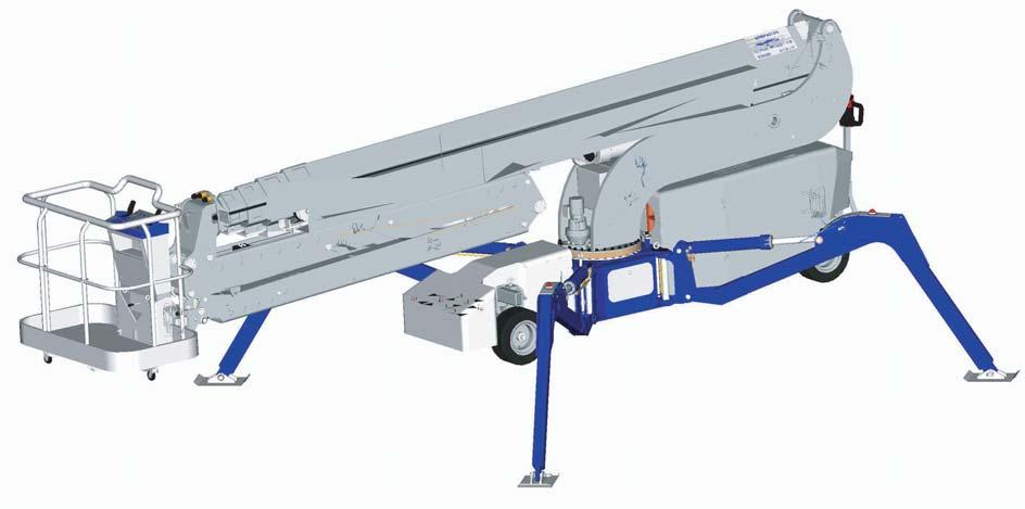
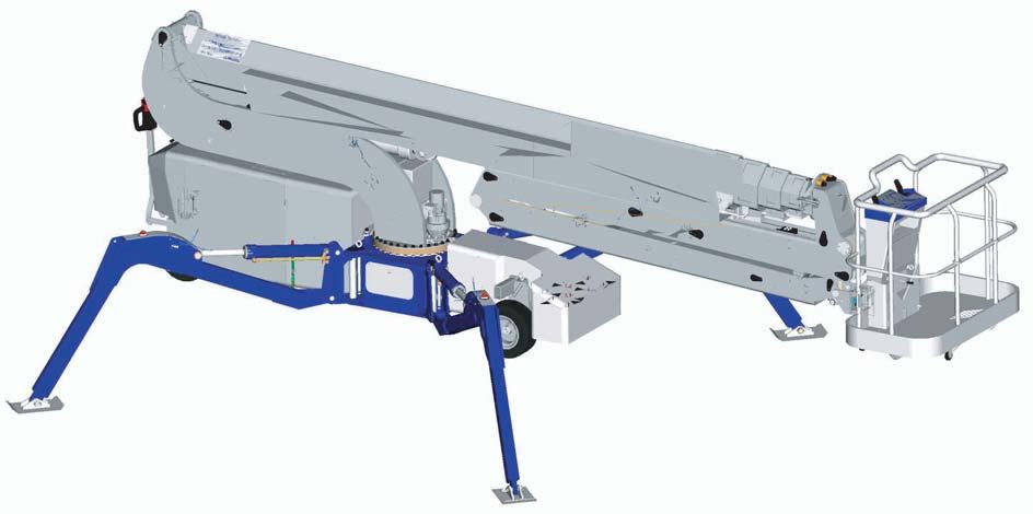
 Red Stowed position Turn on the main switch situated next to the turn switch for the emergency pump at the right side of the platform.")


12 Introduction Turn main switch on Handling by crane If the platform is received on truck and has to be handled with crane the platform can be lifted off the truck by a crane. The outriggers shall be placed in narrow position (orange) Red Stowed position Turn on the main switch situated next to the turn switch for the emergency pump at the right side of the platform. Turn the key switch to control from chassis Orange Standardposition Green Yellow (not transport position) and the crane must be attached to the fixing points at the outriggers. Length of lifting chains on crane must be adjusted to give balance of the platform as centre of gravity is not located in the middle of the outriggers attach points. See fig 1 Fig Transportation in containers The following precautions must be observed/ noticed when receiving these machines, in the order described below. Please note that the description below is only in a short form, and that the appropriate sections of this document have to be read and followed thoroughly. Check battery capacity indicator (round instrument) at the Chassis control panel (suppl. A) at the front of the platform. Do not attempt to open any boxes containing electrical components, when mains are connected to the machine. Contact with the main supply can cause injury or death. Before opening the boxes with electrical components, mains must be disconnected from the machine. Repair work with 24V DC power connected may only be performed by authorized personnel Remove wooden blocks The wooden blocks supporting the chassis shall be removed by the means of ordinary hand tools. Please make sure that the upper control box does not interfere with the container roof Remove ropes The platform is strapped to the container with ropes etc. These ropes can be used for later strapping of the machine on a truck flatbed, etc. Introduction
13 Important As soon as possible, the platform must be connected to mains outlet and charged. Avoid leaving the platform for several days without charging. Use a ramp while driving the platform of the container. As soon as the platform has left the container set the axle width to the widest position possible. (Not the crawler version of the Falcon platform) Rev. Jan2007 Introduction
14 2.0 Supplements
15 Supplement A 15 Rev. Jan2007 Supplements
16 16 Supplement B 10 A #p Max. MAX! Max. Max. #w #d #e #f #g A B Joystick 1 Joystick 2 #x #v #c #i #a #s #q #s #z #z 1 #y #y #n #o #r 3+4 B #a #l B A #m #k Supplements


17 Description of the Control Panels 17 Chassis and Basket #a EMERGENCY STOP BUTTON Pushbutton. #e SIGNAL BASKET LOCKED #b BATTERY INDICATOR It is recommended not to work with the SPIDER with battery capacity below 20%.#f CAUTION SIGNAL MOVEMENTS BLOCKED #c INFORMATION SIGNAL MAIN BOOM IN CENTER #g SIGNAL BASKET OVERLOAD #d SIGNAL STABILITY #h PUSHBUTTON STARTS PUMP FOR OUTRIGGERS Rev. Jan2007 Supplements

 #k PUSHBUTTON")


18 18 FOLLOWING DECALS ARE FOR THE CHASSIS CONTROL PANEL ONLY #i TURNABLE SWITCH FOR DIESEL ENGINE (Option) #k PUSHBUTTON SLEWING COUNTER- CLOCKWISE #j TURNABLE SWITCH 220V or 400V AC PUMP (Option) #l PUSHBUTTON SLEWING CLOCKWISE #m PUSHBUTTON EXTEND TELESCOPES #n PUSHBUTTON RETRACT TELESCOPES Supplements

19 19 #o PUSHBUTTON MOVING LINK ARM SYSTEM #s TURNABLE SWITCH #p PUSH BUTTON MOVING LINK ARM SYSTEM #t TURNABLE SPRING LOADED (Optional) SWITCH FOR BASKET ROTATION #q PUSHBUTTON MAIN BOOM UP #u TURNABLE KEY SWITCH WITH 3 POSITIONS O = Off = Operate the SPIDER from the control panel in the basket. #r PUSH BUTTON MOVING MAINBOOM DOWN = Operate the SPIDER from the chassis control panel. Rev. Jan2007 Supplements
 When using the platform functions choose between Basket rotation clockwise or counter-clockwise.")


 will move up when using one of the outrigger functions.")
20 20 #y #v PUSHBUTTON OUTRIGGER SET UP THESE INFORMATIONS ARE FOR THE BASKET CONTROL PANEL ONLY! PICTOGRAM FOR THE SELECTOR SWITCH. (Top of left joystick) When using the platform functions choose between Basket rotation clockwise or counter-clockwise. By pressing the selector switch to the left, marked with a dot the basket rotation will be clockwise. By pressing the selector switch to the right, marked with two dots the basket rotation will be counter-clockwise. To stop the basket rotation release the selector switch. #z #w CAUTION SIGNAL LOW BATTERY CAPACITY PICTOGRAM FOR THE TOP OF THE LEFT JOYSTICK By pressing the selector-switch marked with a dot continously the outrigger(s) will move down when using one of the outrigger functions. By pressing the selector-switch marked with two dots continously the outrigger(s) will move up when using one of the outrigger functions. Outrigger functions: #x TURNABLE SWITCH #a1 THIS IS ONLY FOR CRAWLER PLATFORMS TALLER THAN 32 METERS/105 FEET. Choise for front track unit Choose between raising or lowering the front belts from the ground during operation it its possible to control the the platforms free hight. Especially needed when working in uneven terrain. Control of the outriggers. Complete pictogram. Supplements
 of the selector switch at the top of the left joystick.")
 of the selector switch at the top of the left joystick.")
 of the selector switch at the top of the left joystick. Movements for Outrigger 3&2.")
21 21 Movement of Outrigger 1. By moving the joystick up diagonal to the right, Outrigger 1 moves up or down depending on position (1 or 2) of the selector switch at the top of the left joystick. Movements for Outrigger 3&4. By moving the joystick to the left Outrigger 3&4 move up or down depending on position (1 or 2) of the selector switch at the top of the left joystick. Movements for Outrigger 1&2. By moving the joystick to the right Outrigger 1&2 move up or down depending on position (1 or 2) of the selector switch atthe top of the left joystick. Movements for Outrigger 4. By moving the joystick up diagonal tothe left, Outrigger 4 moves up or down depending on position (1 or 2) of the selector switch at the top of the left joystick. Movements for Outrigger 2. By moving the joystick down diagonal to the right, Outrigger 2. moves up or down depending on position (1 or 2) of the selector switch atthe top of the left joystick. Movements foroutrigger 4&1. By moving the joystick up, Outrigger 4&1 move up or down depending on position (1 or 2) of the selector switch at the top of the left joystick. Movements for Outrigger 3&2. By moving the joystick down, Outrigger 3&2. move up or down depending on position (1 or 2) of the selector switch at the top of the left joystick. Movements for Outrigger 3. By moving the joystick down diagonal to the left, Outrigger 3 moves up or down depending on position (1 or 2) of the selector switch at the top of the left joystick. Rev. Jan2007 Supplements
.")
 are selected. Driving backwards. By pulling the joystick the platform will drive against the operator.")
 are selected. Driving forwards. By pushing the joystick up the platform will drive in the direction away from the operator.")

22 22 Complete pictogram for driving. By moving the joystick down to the left, the platform will turn CW and drive against the operator at the same time. By moving the joystick up to the left, the platform turns CCW and drive away from the operator at the same time. Pictogram (Horizontal surface). Left side of the pushbutton at the top of the joystick marked with 1 dot is left side of the push button pushed down. Low traction (Higher speed) are selected. Driving backwards. By pulling the joystick the platform will drive against the operator. Pictogram (Surface with gradient) Right side of the pushbutton in the top of the joystick marked with 2 dots is right side of the push button pushed down. High traction (Lower speed) are selected. Driving forwards. By pushing the joystick up the platform will drive in the direction away from the operator. When the front tracks or wheels are turned, and the operator lets go of the joystick, the front tracks/wheels will not automatically go back to middle position. The front tracks/wheels will stay in the turned position until it is turned in the opposite direction. By moving the joystick up to the right, the platform turns CW and drives away from the operator at the same time. Supplements
 Pic.")
23 Supplement C Supplement D 23 Pic. I Battery Main Switch Decal for Emergency lowering at turret Pic. II Outrigger Indicator Pic. III Emergency kit with standard handle (green frame = for track version) Pic.IV Emergency tools Rev. Jan2007 Supplements
24 24 Supplement E Supplements
25 3.0 Electrical equipment In this chapter you will find: Engaging the electrical system Stability system Controls on the platform About the charger Basket rotator (Option) Acoustic signals
26 26 Do not attempt to open any boxes containing electrical components when power is connected to the machine. The mains supply can cause injury or death. Before opening the boxes containing electrical components the mains must be disconnected from the machine. Repair work with 24V DC power connected may only be performed by authorised personnel Engaging the electrical system The platform is equipped with a main switch, which is located at the right side of the platform, next to the switch for the emergency pump. Turn the main switch to position ON Choice of control The platform can be operated from the Chassis control panel (suppl. A) or from the control panel in the basket (suppl. B). The key switch (#p) for choice of control panel is located at the Chassis control panel (suppl. A). Remove the key to prevent unauthorised use of the platform. When the key switch (#p) is in position O, the platform is turned off. Do not attempt to use the platform if red indicator lights at the outriggers are not ON, when the outriggers are in the stowed position or without a load. If the red STABILITY indicator lights are out when the outriggers are lifted from the ground, the safety system has a malfunction. Failure in the safety system can cause injury or death. Call an authorised service centre immediately Stability system The platform is equipped with an automatic system by which mechanical/electrical measurement secures that the platform always has the minimum required stability. If the minimum required stability is reached the platform automatically CUTS OUT the functions that would reduce the stability further. During minimum stability: CUT OUT the red indicator light at the outriggers with minimum pressure, will come on and the red indicator light STABILITY at the Basket control panel (Suppl. B) and at the Chassis control panel (suppl. A) will also come on. If only the red indicator light STABILITY at the Basket control panel (Suppl. B) and at the Chassis control panel (suppl. A) comes on, a secondary CUT OUT stability system is activated and notices deflection of the main boom. The only functions that are free during CUT OUT and secondary CUT OUT will be: RETRACT TELESCOPE MAIN BOOM UP These functions will increase the stability. By turning the main switch to position, or the red indicator lights on the outriggers shall light up when the outriggers are in stowed position or without a load. Always check the red indicator lights (Stability system) at the outriggers before starting to work. Electrical Equipment
27 27 Do not attempt to use the platform if red indicator lights at the outriggers are not ON, when the outriggers are in the stowed position or without a load. If the red STABILITY indicator lights are out when the outriggers are lifted from the ground, the safety system has a malfunction. Failure in the safety system can cause injury or death. Call an authorised service centre immediately. injury or death. Call an authorised service centre immediately Controls on the platform (Movements and outriggers) Chassis control panel (suppl. A) Active: By turning the key switch (#u) at the control panel to Position Chassis the Chassis control panel (suppl. A) is active, and can control the movement of the main boom, telescopes, slewing, jib and basket jib by the push button. The outriggers are controlled by hydraulic valves, activated by the control handles marked 1, 2, 3, and 4 according to the outriggers numbers, located under the chassis control panel Outriggers at the front of the platform. Driving the platform are done by the driving unit or the portable control box. Control panel in the basket Active: By turning the key switch (#u) at the control panel to position Basket The Basket control panel (Suppl. B) is active, and controls movement of the main boom, telescopes, slewing, jib and basket jib, and as option, outriggers and driving functions by the joysticks and selector switches Charge indicator On the charging box, under the cover in the rear end, you ll find small lights (LED). When the charger is connected to the mains, the ON LED will flash for about 5 seconds. In these first 5 seconds the charger reads all input signals and calculates the necessary output voltage. After 5 seconds the charger will switch on, and the ON LED illuminates. There are also LEDs for the following functions Charge voltage Charge current Boost Equalise Float charge Failure Battery capacity Indicator (Supplement A, #b) The battery capacity indicator is located at the Chassis control panel (suppl. A). The battery capacity indicator displays the capacity of the battery system in 9 levels of capacity, which are indicated by digital steps (Yellow lights). When the capacity is below 50%, the remaining 3 yellow lights and an indicator light at the Basket control panel (Suppl. B), shines continuously, to indicate the capacity of the battery system is low. It is important to charge the battery system now. One yellow light for every 10% capacity. Red light indicates capacity below 20%. CAUTION Do not operate the platform if capacity is below 20%. After long distance travelling you must secure that there is enough capacity to work with the platform, otherwise you must recharge the battery Basket rotator (Option) The platform can as optional be equipped with a basket rotator, which can be controlled by the Basket control panel (Suppl. B) and from the Chassis control panel (suppl. A). Rev. Jan2007 Electrical Equipment
28 Acoustic signals The platform is equipped with an acoustic pulsing signal when using the chassis functions (Driving and outriggers functions). A slope alarm gives an increasing pulsing acoustic signal, when the chassis reach a dangerous angel (There is danger that the platform will turn over) according to horizontal. Electrical Equipment
29 4.0 Hydraulic equipment In this chapter you will find: A short description of the hydraulic equipment
30 Hydraulic equipment Power transmission The platform is equipped with an oil pump which is driven of the 24V DC motor. Furthermore proportional valves, filters and the oil tank in the turret section enables power transmission and a hydraulic oil pump driven by a diesel engine Activation of main boom Telescopes, jib, basket jib and basket rotator Movements of main boom and link arm system are done by hydraulic cylinders. Telescoping is done by hydraulic cylinders and a chain system. A hydraulic actuator does the movement of the basket rotator (Optional). If a chain is too slack, the platform should be brought to the ground immediately. Operating the platform with a broken chain, can cause injury or death. Call an authorised service centre immediately Activating outriggers 4 pcs. hydraulic cylinders provide movements of the outriggers (Vertical). The cylinders have safety valves Basket locked If the basket tilts more than 10º it will automatically secure its position. If possible move the main boom or the Link arm system in the opposite direction, until the basket is back at horizontal level Basket levelling The basket is levelled by a hydraulic/electronic levelling system supplied from a separate 24 V DC oil pump. Follow the safety instructions carefully Emergency lowering In case of electrical fault or in emergency situations the platform can be operated manually by the emergency (hydraulic) valves located at the turret. When operating the platform from the ground by engaging the hydraulic valves directly the safety system is not functioning and the operator must pay highly attention to every move and follow the emergency lowering procedure. Telescopes In is the only function to be used until the telescopes are fully retracted. Failure to do so can cause injury or death. Call an authorised service centre immediately Controls of the platform The platform can be operated from the Chassis control panel (suppl. A) located at the front of the platform or from the Basket control panel (Suppl. B). A turnable key switch located at the Chassis control panel (suppl. A, #u), does the selection of control panel. Hydraulical Equipment
31 5.0 Operators Instructions In this chapter you will find: Operators Instructions Driving the platform Self-propelled with driving unit Wheel Models until 32 meter Sections marked blue Driving the platform Self-propelled with portable box Crawler Models and wheel models taller than 32 meter Sections marked green Driving the platform from the transportable driving unit Setting up the outriggers from Chassis control panel Setting up the outriggers from the Basket control panel Setting up outriggers automatically (Option) Stowing the outriggers Mounting the basket About the diesel engine Operating the platform Joystick description Basket control panel Description Chassis control panel Description

32 Driving the platform Self-propelled drive All: The driving unit have two control facilities (Speed values): (Portable box) For crawler models and wheel models taller than 32 meter/105 feet. The platform is self-propelled by a driving unit which means that it can be moved to a job site and back. The platform can be driven from the ground by a Transportable driving unit placed at the front of the platform or from the right joystick at the Basket control panel (Suppl. B) (Joystick 2) The default value The platform drives fast, but with a low traction. The platform drives slowly, but with maximum traction. For driving the platform on surfaces with a gradient > 5 Option for track models taller than 32m/105ft: Fig. 4 Portable driving box Driving the platform self-propelled drive (Driving unit) For wheel models until 32 meter fig. 3 Driving unit The platform can be driven from the ground, by the driving handle at the front of the platform or as option, from the right joystick at the Basket control panel (Suppl. B) (Joystick 2). Differential blocking system for tracks. The tracks are equipped with a hydraulic differential system to make it easier to turn in very uneven terrain which could make the tracks spin. When the buttons 1 or 2 is selected for more than 1,5 sec. the differential blocking is activated and all tracks are driving. The platform is equipped with an acoustic pulsing signal. When using the chassis functions (driving and outrigger functions) a slope alarm gives a quick pulsing acoustic signal, if the chassis reaches a dangerous angle (If the danger is that the platform will turn over). Before using the chassis functions (Driving and outrigger functions): Retract the telescopes completely Folding in the link arm Main boom in centre (the green information signal (Suppl. A + B, #c) at the control panels comes on.) Main boom down Operators instructions
 on the Chassis control panel (suppl. A) to position Chassis. 3. The platform can now be driven from the driving handle (fig.")
33 Driving the platform 1. Make sure that the main switch (Located on the side of the platform next to the emergency pump) is in position ON The driving functions according to the labal below. 2. Turn the key switch (#u) on the Chassis control panel (suppl. A) to position Chassis. 3. The platform can now be driven from the driving handle (fig. 3 wheel models until 32 meter) or from the joystick at the transportable driving unit (fig. 4 crawler models and wheel models taller than 32 meter.). It is recommended that the operator wears the belts of the portable driving box. A: From portable box (Crawler models and wheel models taller than 32 meter/105 feet) For crawler versions Chose traction (Speed or Optional), at the push button at the top of the joystick. The chosen value is the active value when the operator lets go of the button until another choice is made. The platform is driven from the joystick. The joystick is one-hand controlled by a trigger which means the operator must push the trigger continuously when activating one of the driving functions. For wheel versions taller than 32 meter Descriptions of the driving functions according to the label at the Portable driving box The operator must stand in front of the platform facing the front of the platform Fig. 6 Joy-stick at the portable control box The transportable driving units equipped with an emergency stop button. By pushing the emergency stop button all functions of the platform will stop (Chassis and platform functions). To deactivate the emergency stop button, turn the button and it will automatically deactivate If the operator lets go of the joystick it will automatically return to middle position and the function stops. CW = Clock wise CCW = Counter clock wise Rev. Jan2007 Operators Instructions
34 34 1. Pictogram (Horizontal surface) at the left side of the push button in the top of the joystick marked with 1 dot If the left side of the push button is pushed down low traction (Higher speed ) is selected. 2. By moving the joystick up, backward driving is selected and the platform will drive away from the operator. B: From driving handle 3. Pictogram (Surface with gradient) at the right side of the push button in the top of the joystick, marked with 2 dots Is right side of the push button pushed down high traction (Lower speed with blocking) is selected. 4. By moving the joystick up to the right, the platform turns CW and drives away from the operator at the same time. 5. By moving the joystick to the right, the front tracks will turn/rotate CCW Track models until 32 meter. By moving the joystick to the right, the tracks will turn/rotate CW 6. By moving the joystick down to the right, the platform turns CCW and drive against the operator at the same time. 7. By moving the joystick down, forward driving is selected and the platform will drive against the operator. 8. By moving the joystick down to the left, the platform will turns CW and drive against the operator at the same time. The SPIDER can be driven by the driving handle located at the front of the SPIDER. Select the speed value or optional by the push buttons. By moving the speed controllers (C) away from the operator, backward driving is selected and the platform will drive away from the operator. By moving the speed controllers (C) towards the operator forward driving is selected and the platform will drive against the operator. A. Button for single wheel drive B. Button for 2-wheel drive (Option) C Proportional speed controller 9. By moving the joystick to the left, the front tracks will turn/rotate CW. Track models until 32 meter. By moving the joystick to the left, the tracks will turn/rotate CCW. 10. By moving the joystick up to the left, the platform turns CW and drive away from the operator at the same time. Operators instructions
 is in position ON. 2. Turn the key switch (#u) at the Chassis control panel (suppl. A) to position Basket 3.")
35 Driving the platform Self-propelled drive from the Basket control panel (Suppl. B) (Option at wheel models) 1. Make sure the main switch (Located at the side of the platform next to the emergency pump) is in position ON. 2. Turn the key switch (#u) at the Chassis control panel (suppl. A) to position Basket 3. Enter the basket (Max. 200 kg) 4. Turn the selector switch (#x) at the Basket control panel (Suppl. B) to position B for chassis functions. Wheel models until 32 meter The axle width of the rear set of wheels is adjustable in four positions: 0,79 1,02 1,20 1,40 m. (2,6 ft. 3,35 ft. 3,9 ft. 4,6 ft.) 1. To change the axle width on the rear set of wheels, place the outriggers in standard position-green for axle width: 0,79 1,02 1,20 m. (2,6 ft. 3,35 ft. 3,9 ft. 4,6 ft.) Place outrigger 2+3 in Yellow position for axle width 1,40 m. (See section 5.2) 2. Lift all three wheels off the ground by the outriggers (See section 5.2) 3. Remove locking pin (A) for rear axles. 4. Adjust the axle width to the needed by pushing/pulling the handle (B) at the guide for axle width. Fig Lock axle position with locking pin (A). 5. Drive the platform by the right joystick according to the label below. A B Fig. 8 The joystick is equipped with a selector switch in the top marked with 1 dot in the left side for low traction (default value) and 2 dots in the right side for high traction (Option). The platform will keep the selected value until the selector switch is engaged again. The joystick is equipped with one hand control (A trigger, press it when activating the joystick). To drive the platform forward push the joystick. To drive backwards pull the joystick. To turn see section for detailed driving. It is possible to turn the front track/wheel and drive the platform at the same time. All movements of the platform are proportional Change the axle width Always use the maximum possible axle width that space allows. B Rev. Jan2007 Operators Instructions
 1.")
36 36 When the rear axles are not locked with the locking pin, the rear axle can fall out and the platform may tip over, causing serious injury or death. Wheel models above 32 meter The axle width of the rear set of wheels is adjustable in two positions: 1. completely out 2. completely in (narrow/stowed) 1. Lift all wheels off the ground by the outriggers (See section 5.2) 2. Turn the switch for the electrical emergency pump on. 3. Move the handle untill both axles are completely out or completely in. 5.2 Setting up the outriggers General Before using the chassis functions (Driving and outrigger functions): Retract the telescopes completely. Fold in the link arm Main boom in centre (The green information signal (E) at the control panels lights up). Main boom down. 1. Make sure that the battery main switch is in position ON. The battery main switch (Suppl. C, Pic. I) is located at the side of the platform next to the switch for the emergency pump. Always remember to keep the platform connected to mains if possible. 2. When using the functions according to the chassis (Driving and outriggers) the platform gives an acoustic pulsing signal. 3. To set up the outriggers from Chassis control panel (suppl. A) turn the key switch (#u) to position for Chassis Control. 4. To set up the outriggers from Basket control panel (Suppl. B) turn the key switch (#u) to position for Basket Control. Do not attempt to drive the lift if the axles are not completely out or completely in. The platform may tip over, causing serious injury or death. When driving the platform with the axles in the stowed position, keep the platform on hard, flat ground and in low speed. If the platform is driven on a slope it can tip over and cause injury or death. 5. When the key switch at the Chassis control panel (suppl. A) is in position Chassis control or Basket Control. The red light on all 4 outriggers and the red stability indicator light, on the platform control panels, at the chassis and in the basket, must be on when the platform is in stowed position or if the outriggers are without load. Make sure always to check the red Stability indicator lights while the platform is in stowed position. IMPORTANT Use the widest axle width possible at all times. Operators instructions


37 37 Do not attempt to use the platform if the red lights on the outriggers or the STABILITY indicator lights are not ON when the outriggers are in stowed position or the outriggers are without a load. If the red STABILITY indicator lights are out when the outriggers are lifted from the ground the safety system has a malfunction. Failure in the safety system can cause injury or death. Call an authorised service centre immediately. Fig. 12 Outrigger turned away from the platform 6. Mount the outrigger plates at the outriggers: Turn the outriggers away from the platform by lifting the locking bolts and turn the outrigger away. Fig. 13 Locking pin Fig. 14 Foot plate mounted and secured Fig. 9 Locking bolt Fig. 15 Axle and foot plate Outrigger plates must always be mounted at the outrigger and secured before attempting to lift the platform off the ground. Fig. 10 Locking bolt lifted Fig. 11 Locking bolt 7. Dismount the locking pin from the axle and remove the axle. Mount the foot plates at the outriggers and secure it with the axle and locking pin 8. When the four outrigger plates are secured the outriggers must be placed and secured/ locked with the locking bolt. Setting up the platform on soft ground can make the platform unstable and cause serious injury or death. Only set up the platform on hard flat ground. Load applied to the ground is given in the technical data. Setting up the outriggers General 9. Each outrigger can be placed in three different positions. The outreach of the platform depends of the load in the basket and the Rev. Jan2007 Operators Instructions
 and always lock with the locking bolt to the chassis frame.")
38 38 positions of the outriggers. (See outreach diagram) Fig. 18: Locking bolt. Locking bolt must always be in position before attempting to set up the platform on outriggers. 8. Place the outriggers in the best possible horizontal position. If possible use the standard position Green (45º to the chassis) and always lock with the locking bolt to the chassis frame. The outriggers must as a minimum be in position Orange before the outriggers are lowered, otherwise the outriggers will collide with the chassis. Fig. 16 Outrigger positions Fig. 17 Outrigger in standard position. Fig. 18 Locking bolt Fig. 16: Transportation position Red. Only for transportation to achieve the min. width 1,2 m. (Stowed position). Position Orange (30º to chassis). Position Green (45º to chassis) Standard. Position Yellow (60º to chassis). When the four outriggers has been placed and secured/locked to the chassis frame the outriggers can be lowered by the outrigger control handles placed underneath the Chassis control panel (suppl. A) or by the Basket control panel (Suppl. B) (Option). CAUTION When lowering the outriggers make sure that there is no interference with the pumps and diesel engine. Do not lower the outriggers when they are locked in the stowed position. This is not a working position and can cause interference with chassis resulting in structural damage. When lowering the outriggers, do not lift the platform more than 0,6 m. from the ground. The platform does not stop automatically. Failing to do so can cause injury or death. If the outrigger base of the outrigger is not locked to the chassis frame the outriggers can turn, resulting in instability which can cause injury or death. Locking bolt for securing the outrigger base to the chassis frame must always be in position before attempting to lift the platform off the ground. Fig. 17: Outrigger base an chassis frame. Operators instructions
 Overview operations locations Description: 1 Outrigger control-handle for outrigger 1 up/ down 2 Outrigger control-handle for outrigger 2 up/ down 3 Outrigger control-handle for outrigger 3 up/")
39 Setting up the outriggers from Chassis control panel (suppl. A) Overview operations locations Description: 1 Outrigger control-handle for outrigger 1 up/ down 2 Outrigger control-handle for outrigger 2 up/ down 3 Outrigger control-handle for outrigger 3 up/ down 4 Outrigger control-handle for outrigger 4 up/ down 5 Push button for START PUMP 6 Spirit level On crawler models: (Fig 19a) A. Turns the tracks to the right - forward or backward. (Handle not mounted, only for emergency) B. Turns the tracks to the left - forward or backward. (Handle not mounted, only for emergency) On wheel models: (Fig 19b) Fig 19a Outrigger control handles at crawler models A. Driving the platform forward/backward (Handle not mounted, only for emergency) B. Valve for turning the front wheel clockwise/ counter-clockwise (Handle not mounted, only for emergency) Fig 19b Outrigger control handles at wheel models Rev. Jan2007 Operators Instructions
 at the Chassis control panel (suppl. A). 4.")
40 40 Setting up the outriggers from the chassis To set up the outriggers do as followed: 1. Place the outriggers in the chosen position. 2. Turn the key switch at Control panel-chassis to position chassis. 3. Push the button START PUMP (#h) at the Chassis control panel (suppl. A). 4. Bring the outriggers to the ground by the control handles. It is recommended to bring all 4 outriggers in contact with the ground one by one. 5. Lower the outriggers two at the time (1 and 4 together - 2 and 3 together) by the outrigger control handles to give an equal pressure on each outrigger. 6. The platform shall be lifted from the ground until all tracks/wheels no longer have contact with the ground. When the outriggers are pressed to the ground the red stability indicator lights, at the outriggers shall turn off. When positioning the outriggers on the ground it is important to ensure that all limbs are kept clear of the outriggers, outrigger plates and any other moving parts. Failing to do so can cause injury or death. Setting up the platform out of horizontal level to the ground can give instability and cause injury or death. The platform must be set up with chassis in horizontal level. The outreach of the platform depends on how the outriggers are placed. Wider outrigger span and lower basket load means longer outreach. In order to achieve the maximum working height the platform must be raised 0,6 m./2ft off the ground measured from the ground to underneath the wheels. (see outreach diagram) Pay attention to the free rotation af the turret! 7. When setting up the outriggers, the platform must be on hard flat ground. Make sure the platform is in horisontal level by checking the spirit level located at the chassis frame. Fig. 20 Spirit level Operators instructions
41 Setting up the outriggers from the Basket control panel (Suppl. B) (Option) To set up the outriggers from the Basket control panel (Suppl. B) do as follows: 1. Place the outriggers in the chosen position. 2. Turn the key switch at Control panel-chassis to position Basket. 3. Enter the basket. 4. Turn the selector switch (#x) at the Basket control panel (Suppl. B) to position chassis marked with a B Fig. 21 Turnable switch 5. Use the left joystick to control the outriggers according to the left label on Basket control panel (Suppl. B) marked with a B. 6. Bring the outriggers to the ground by the left joystick and press left side of the selector switch marked with one dot. 7. Lower the outriggers two at a time (1 & 4 together and 2 & 3 together) by the Left joystick to give an equal pressure on each outrigger. When positioning the outriggers on the ground it is important to ensure that hands, feet etc. are kept clear of the outriggers, outrigger plates and any other moving parts. Failing to do so can cause injury or death. Setting up the platform out of horisontal level to the ground can give instability and cause injury or death. The platform must be set up with chassis in a horisontal level. Do not attempt to use the platform if the red indicator lights at the outriggers are not ON when the outriggers are in stowed position or the outriggers are without a load. If the red STABILITY indicator lights are out when the outriggers are lifted from the ground, the safety system has a malfunction. Failure in the safety system can cause injury or death. Call an authorised service centre immediately. The outreach of the platform depends on how the outriggers are placed. Wider outrigger span and lower basket load means longer outreach. In order to achieve the maximum working height the platform must be raised 0,6m/2ft. off the ground, measured from the ground to underneath the wheels. (see outreach diagram). 8. The platform shall be lifted from the ground until all tracks or wheels no longer have contact with the ground. When the outriggers are pressed to the ground the red stability indicator lights at the outriggers shall turn off. 9. When setting up the outriggers the platform must be on hard flat ground. Make sure the platform is in horizontal level by checking the spirit level located at the link arm system. Rev. Jan2007 Operators Instructions
42 Setting up outriggers automatically (Option) As option the outriggers can be set up automatically in horizontal level and the pressure in the hydraulic system equalised by a push button at the Chassis control panel (suppl. A, #v) or by a push button at the Basket control panel (Suppl. B, #v) It is recommended only to use automatic set up for the outriggers at horizontal surfaces and with the outriggers in standard position (45 to chassis Green). 1. Bring the outriggers in position, and lock them with the locking bolt. (According to the procedure in section 5.2) 2. Push the button (#v) continuously and the outriggers will be set up. 3. The platform is in horizontally level and the pressure in the hydraulic system of the outriggers is equalized when the green Information signal (C) starts flashing, and the operator can now release the button (#v). 4. If the platform needs to be lifted higher from the ground repeat procedure 2 and 3. To lift the outriggers from the ground use the control handles for the outriggers (Chassis control panel or the joystick (Control panel Basket). Do not attempt to use the platform if the red indicator lights at the outriggers are not ON, when the outriggers are in stowed position or the outriggers are without a load. If the red STABILITY indicator lights are out when the outriggers are lifted from the ground, the safety system has a malfunction. Failure in the safety system can cause injury or death. Call an authorised service centre immediately Stowing the outriggers The outriggers can be stowed in the following order: 1. Retract the telescopes 2. Fold in the link arm system (The jib and basket jib) 3. Main boom in centre 4. Move the main boom down 5. Leave the basket 6. Dismount the basket, if needed 7. Lift the outriggers from the ground two by two (1 & 4 together - 2 & 3 together) by the outrigger handles 8. Remove the outrigger plates if needed. 9. Bring the outriggers in stowed position and lock them with the locking bolts In order to achieve the minimum height, width and length according to the technical data, the basket and the outrigger plates must be dismounted and the outriggers placed in stowed position (Red). Do not set up the platform, when the outriggers are in Red position (Suppl. C, Pic II) (Stowed position). This is ONLY transport position. Failing to do so can be a cause for injury or death. Operators instructions
 3.")
 The platform, if equipped with a diesel engine, it can be started and stopped from the turnable switch on the Chassis control panel (suppl.")
43 Before using the platform Mounting the basket 1. Mount the basket at the two brackets (A) at the console for the Basket Control Panel. 2. Secure the basket with the two locking pins (B) 3. Safety belt can be mounted at the two fixingpoints (C) Diesel engine (Optional for wheel models) The platform, if equipped with a diesel engine, it can be started and stopped from the turnable switch on the Chassis control panel (suppl. A, #i) or at the Basket control panel (Suppl. B, #i) The turnable switch (#i) have 3 positions O = Diesel engine stopped = Ignition for diesel engine I = Diesel engine starter/preheater Fig. 22 Mounting the basket When mounting the basket make sure that the basket is locked properly. A basket not locked properly can fall of and cause injury or death. When the platform is used for welding work the platform has to be unplugged and the outriggers have to be placed on rubber mats Power supply If mains are not available it is possible to work without being connected to the mains outlet. To avoid discharging the batteries the battery charger shall, if possible, always be plugged in. Optional: 24V DC motor and diesel engine. Diesel engine (option on wheel models) AC motor (option). The turnable switch comes on red when the diesel engine is started. If the red light fl ashes in the turnable switch the fuel level is low. Refi ll fuel as soon as possible. By turning the switch (#i) to I, hold it till it starts (app. 30 seconds). The engine is preheating before it starts. By turning the switch (#i) to ignition and not starting the engine, it will after app. 10 sec. automatically cut of. After this it is necessary to turn the switch (#i) back to position O and then to position I. REMARK: The turnable switch (#i) activates only the functions by change. As an example: If the diesel engine is operated from the Chassis control panel (suppl. A) turn the key switch (#u) to position Chassis and turn the switch (#i) to position I. When the diesel motor starts let go of the switch (#i), and the switch returns automatically to position The switch (#i) at the Basket control panel (Suppl. B) will still be in position O. The red light in the switch will come on to indicate that the motor is running. To turn off the engine from the Basket control panel (Suppl. B) turn the key switch (#u) to position Turn the switch (#i) to position and then to position O and the motor will stop/turn off. Rev. Jan2007 Operators Instructions


44 44 Diesel engine (Lombardini) Generator (Honda) The information lights for the diesel engine are placed at the end of the platform If a generator (available as option) is mounted, it is operated from the control panel located at the generator. When using the generator, place the plug (see picture below) in one of the AC receptacles, and the generator supplies the battery charger, and the mains outlet in the basket. Fig. 23 Plug 1. Air fi lter. The light comes on when the filter is blocked 2. 12V/24V generator. The light comes on when there is no charging to the 12V/24V generator 3. Oil pressure. The light comes on when oil pressure of the diesel motor is to low 4. Water temperature. The light comes on at high temperature When the diesel engine is running it will charge at the batteries of the platform. When the diesel engine is running all functions of platform will be power supplied from the diesel engine. Other pumps will not be started e Service- and maintenance of the diesel engine is according to the Operators instructions for the Lambordini diesel engine. Operators instructions
45 5.4 Operating the platform 45 Personnel who needs to gain access i.e. for maintenance and cleaning operations can use the platform. The platform is not insulated for working with or near high voltage installations and the platform may not be used for any other purpose than to give access for personnel. The platform may not be used as a crane and large objects may not be placed in the basket or at the boom i.e. large label or windows. Contact between platform or basket and fi xed objects i.e. buildings shall be avoided. The basket is not insulated for work with or near high voltage installation. Work in assured clear distance from electrical power lines. Failing to do so can result in electrocution causing injury or death. 1. Turn the fuel valve lever to ON position. 2. Pull the choke knob out to closed position. NOTE: Do not use the choke when the engine is warm or the air temperature is high. 3. Push the Eco throttle switch to position OFF. 4. Turn the engine switch to ON the position. Turn the engine switch shortly to starting position. 5. If there is no battery capacity or at models with manual starter: Pull the starter grip lightly until resistance is felt, then pull the starter grip briskly. 6. Push the choke knob to the open position as the engine warms up. 7. Push the Eco throttle switch to position ECO. Please follow the instructions in the HONDA Owner s MANUAL. Do not attempt to climb outside the basket when it is lifted from the ground. Always make sure you use a safety belt as required by your employer or the appropriate fall protection. Falling from the platform can cause injury or death. Do not attempt to climb on top of the basket or to use a ladder or likewise from the basket. Overloading the platform can cause serious injury or death. Do not overload the basket, or attempt to use the basket or the platform as a crane. Before entering the basket it must be controlled that the basket is properly locked to the basket suspension. Do not attempt to use the platform without the use of a safety belt. The safety belt must be properly locked in the fixing point. Incorrect operating of procedures can cause injury or death. Rev. Jan2007 Operators Instructions
 is in position ON.")
46 46 1. Read the complete manual and the safety instructions, and make sure to perform the daily inspection checks before attempting to use the platform. 2. Set up the platform as according to section Make sure that the battery main switch (Suppl. C, Pic. I) is in position ON. The battery main switch is located at the right side of the platform next to the switch for the emergency pump. 4. The platform can be operated from Basket control panel (Suppl. B) or from the Chassis control panel (suppl. A) in the front end of the platform. To operate the platform from the basket, turn the key switch (#u) located on the Chassis control panel (suppl. A) to position. Always pay attention to the position of the outriggers, turret and Link-arm system while slewing. There can be danger of collision between outrigger(s) and Link-arm system and/or between the turret and outrigger(s). Failing to do so can cause structural damage to the platform. When folding out the Link-arm system, make sure there is no collision between the Link-arm system and the cover(s). Raise the main boom and extend telescopes before folding out the Link-arm system. Failing to do so can cause structural damage to the platform. 5. To operate the platform from the ground, turn the key switch (#u) located on the Chassis control panel (suppl. A) to position. 6. Enter the basket (max. 200 kg.) NOTICE When operating the platform from the basket All movements are proportional When operating the platform from the chassis the movements have predefined speed by push buttons. 7. With the platform in stowed position use the following unpacking procedure according to the label at the Link-arm system to prevent damage to the platform: Fig. 24 Label for the unpacking procedure located at the Link-arm system and turret. Raise the main boom. Extend the telescopes, until there is enough space to fold out the Link-arm system. Before activating the Link-arm system and/or the Jib, the Telescopes shall be extended until there is space between the Link-arm system and the covers. Fold out the Link-arm system. Operators instructions
, the operator must choose between using the platform functions or the chassis functions.")
47 Basket control panel Description Two joysticks control the functions. 47 By operating the platform from the Basket control panel (Suppl. B), the operator must choose between using the platform functions or the chassis functions. The selection is done by a turnable selector switch (#x) which is located on the Basket control panel (Suppl. B). The platform function is marked with an A The chassis function is marked with a B A Fig. 25 Left side B Fig. 26 Right side Selecting the platform functions A-activates only the functions in the left side of the label and in the right side of the label marked with an A, and both with yellow background. Selecting the chassis functions B-activates only the functions in the right side of the label and in the left side of the label marked with a B and both with black background. B A Fig. 27 Joystick The functions at the label left side are controlled by joystick at the left side (joystick 1 Suppl. B) and the functions at the labels right side are controlled by joystick at the right side (joystick 2 Suppl. B). The joysticks are two-hand controlled, by a trigger. When using the joystick press the trigger continuously. The joysticks 1 and 2 are equipped with a selector switch. The selector switch can be pressed in 2 positions. To the right, marked with 2 dots: To the left, marked with 1 dot: The dots refer to the dots at the label. By pressing the selector switch to the left or right, the function of the joystick reefers to the pictogram in the same box as the chosen dot(s). In the pictogram the colour filled part is the active part. Rev. Jan2007 Operators Instructions
48 48 Joystick 1 (Left ) 3. Moving of JIB and Basket JIB. By moving joystick 1 to the left, the jib and the basket jib are folding in (#p). (The jib and the basket jib are not moving 100% simultaneously, therefore it can be necessary to adjust the JIB and Basket JIB one by one.) Fig. 28 Turnable Selector switch (#x) Joystick By pressing the 2 dots only the Basket JIB will fold in, when moving joystick 1 to the left. By pressing the 1 dot only the JIB will fold in, when moving joystick 1 to the left. 4. Movements of JIB and Basket JIB. By moving joystick 1 to the right, the jib and the basket jib are folding out (#o). A B (The jib and the basket jib are not moving 100% simultaneously therefore it can be necessary to adjust the JIB and Basket JIB one by one.) Fig. 29 Left label The selection is done by a turnable selector switch (#x) which is located on the Basket control panel (Suppl. B) Platform functions activated (Yellow) 1. Press the joystick selector switch to and hold it: activates only the JIB. 2. Press the joystick selector switch to and hold it: activates only the Basket JIB. Chassis functions activated (Black) 3. Press the joystick selector switch to and hold it: activates Outriggers DOWN. 4. Press the joystick selector switch to and hold it: activates Outriggers UP. PLATFORM functions (Yellow) LEFT joystick 1 1. Movement of the MAIN BOOM UP By pushing joystick 1 upwards, the main boom will move up (#q). 2. Moving the MAIN BOOM DOWN. By pulling joystick 1 downwards, the main boom will move down (#r). By pressing the 2 dots and hold it and move the joystick to the right only the Basket JIB will fold out. By pressing the 1 dot and hold it and move the joystick to the right only the JIB will fold out. Chassis functions (Black) LEFT joystick 1 1. Moving Outrigger 1. By moving the joystick diagonal up to the right and pressing the 1 dot Outrigger 1 moves down. By moving the joystick diagonal up to the right and pressing the 2 dots Outrigger 1 moves up. 2. Moving Outrigger 1&2. By moving the joystick to the right and pressing the 1 dot Outrigger 1&2 moves down. By moving the joystick to the right and pressing the 2 dots Outrigger 1&2 moves up. 3. Moving Outrigger 2. By moving the joystick diagonal down to the right and pressing the 1 dot Outrigger 2 moves down. By moving the joystick diagonal down to the Operators instructions
49 49 right and pressing the 2 dots Outrigger 2 moves up. 4. Moving Outrigger 3&2. By moving the joystick down and pressing the 1 dot Outrigger 3&2 moves down. By moving the joystick down and pressing the 2 dots Outrigger 3&2 moves up. 5. Moving Outrigger 3. By moving the joystick diagonal down to the left and pressing the 1 dot Outrigger 3 moves down. By moving the joystick diagonal down to the left and pressing the 2 dots Outrigger 3 moves up. Joystick 2 (Right) Fig. 30 Selector switch (#x) Joystick 2 6. Moving Outrigger 3&4. By moving the joystick to the left and pressing the 1 dot Outrigger 3&4 moves down. By moving the joystick to the left and pressing the 2 dots Outrigger 3&4 moves up. B A 7. Moving Outrigger 4. By moving the joystick diagonal up to the left and pressing the 1 dot Outrigger 4 moves down. By moving the joystick diagonal up to the left and pressing the 2 dots Outrigger 4 moves up. 8. Moving Outrigger 4&1. By moving the joystick up and pressing the 1 dot Outrigger 4&1 moves down. By moving the joystick up and pressing the 2 dots Outrigger 4&1 moves up. Fig. 31 Right label The selection is done by a turnable selector switch (#x) which is located on the Basket control panel (Suppl. B). Chassis functions activated (Black). 1. Press the joysticks : activates low traction (Fast speed) 2. Press the joysticks : activates high traction (Low speed) Platform functions activated (Yellow) Rev. Jan2007 Operators Instructions
50 50 Chassis functions (Black) Joystick 2 (RIGHT) Rotation For platforms with wheels or platforms with tracks taller than 32m/105ft, the front wheels or tracks turns. At smaller track models the entire platform turns. 1. Turn/rotate right By moving joystick 2 to the right, the front belt will turn/rotate CW. (When the front tracks/wheels is turned, and the operator lets go of the joystick, the front track/wheel will not automatically go back to middle position. The front trac/wheel will stay in the turned position until it is turned in the opposite direction.) By moving the joystick diagonal up to the right, the platform turns CW and drives forward. By moving the joystick diagonal down to the right, the platform will turn CCW and drive backward. 4. Turn/rotate left By moving joystick 2 to the left, the front track/ wheel will turn/rotate CCW. (When the front track/wheel is turned, and the operator lets go of the joystick, the front track/ wheel will not automatically go back to middle position. The front track/wheel will stay in the turned position until it is turned in the opposite direction.) By moving the joystick up to the left, the platform turns CCW and drive forward. By moving the joystick diagonal down to the left, the platform will turn CW and drive backward. Platform functions (Yellow) Joystick 2 (RIGHT) 1. RETRACT Telescopes By pushing the joystick 2 up (#n) the telescopes will retract. 2. EXTEND Telescopes By pulling joystick 2 down (#m) the telescopes will extend. 3. Slewing COUNTER CLOCKWISE By moving joystick 2 to the right (#k) the turret of platform will slew counter-clockwise. Raise the main boom until it is in horizontal level before slewing is possible. 4. Slewing CLOCKWISE By moving joystick 2 to the left (#l) the turret of the platform will slew clockwise. Raise the main boom until it is in horizontal level before slewing is possible. 5. Basket ROTATION (#y) Pictogram for the push button at the top of joystick 2. When using the platform functions choose between basket rotation clockwise or counterclockwise. By pressing the left push button marked with 1 dot the basket rotation will be clockwise. By pressing the left push button marked with 2 dots the basket rotation will be counter clockwise. To stop the basket rotation release the joystick selector switch. 5. Driving backwards By pulling down joystick 2 the platform will drive backward. 6. Forward driving By pushing joystick 2 up the platform will drive forward. Operators instructions
51 Basket control panel Description of the functions (Suppl. B) Chassis functions and PLATFORM functions 1. Caution signal LOW BATTERY CAPACITY When the red light (#w) comes on the capacity at the battery is below than 50%. If it fl ashes it means that the charger is not connected or it indicates a fault. Please check the charger. If the charger is connected and the red light still shines leave the platform momentarily and let it charge the batteries. If the SPIDER is equipped with a diesel engine, it can be started. 2. Warning signal STABILITY. If the red stability light (#d) on the basket control panel comes on and the platform functions stops the main reason is that the limit for sufficient stability is reached. (This is normally caused by maximum outreach with the given basket load compared to the span of the outriggers) As long as the red lights are shining only the functions that increase stability can be used: RETRACT Telescopes #s MAIN BOOM UP #n 3. Warning signal - Basket LOCKED If the basket tilts more than 10º it will automatically secure its position and the red light (#e) comes on. If possible move the main boom or the Link arm system in the opposite direction, until the basket is back at horizontal level and the red light turns off. (section ) 4. Caution signal MOVEMENTS BLOCKED If the light comes on (#f) the basket jib is out of it s allowed working area (vertical) either upwards or downwards. Only functions bringing it back to allowed working area can be used now. Fig. 32 Movements blocked Green area is allowed working area. 5. Warning signal Basket OVERLOAD If there is an overload of the rated basket load the light (#g) will flash. 6. Diesel Engine By turning the switch (#i) to I, hold it till it starts (app. 30 seconds). The engine is preheating before it starts. By turning the switch (#i) to ignition and not starting the engine, it will after app. 10 sec. automatically cut of. After this it is necessary to turn the switch (#i) back to position O and then to position I. 7. EMERGENCY STOP BUTTON. To release the Emergency stop button (#a) pull it. 8. MAIN BOOM in Centre Information signal (#c). When the main boom is in centre, the green light will come on. Every time the main boom passes the centre the green light will come on for a few seconds. (Option) This light is also used for auto set up. See point 9. Rev. Jan2007 Operators Instructions
52 52 9. AUTO SET UP Outriggers (Option) Push button (#v) automatically sets up the outriggers at horizontal level and equalises the pressure in the hydraulic system of the outriggers. It is recommended, only to use automatic set up for the outriggers at horizontal surfaces and with the outriggers in standard position. (45 to chassis green position at the label) 1. Bring the outriggers in position, and lock them with the locking bolt. (According to the procedure in section 5.2) 2. Push the button (#v) continuously and the outriggers will be set up. 3. The platform is at horizontal level and the pressure in the hydraulic system of the outriggers is equalised, when the green information signal (#c) starts flashing. The operator can now release the button (#v). 4. Does the platform need to be lifted further from the ground, repeat the procedure Chassis control panel Description (suppl. A) 1. Turnable key switch (#u) with 3 positions: When operating the platform from the basket, it is recommended to remove the key to prevent unauthorised use of the platform. 2. Push button. (#h) Start the pump for the outriggers. 3. Emergency stop button. To release the Emergency stop button, (#a) pull it. 4. Turnable switch (3 positions) ON/OFF for the diesel engine (#i) For turning the diesel engine on, turn the switch to position I. (By turning the switch to I, hold it till it starts (app. 30 seconds). The engine is preheating before it starts. By turning the switch to ignition and not starting the engine, it will after app. 10 sec. automatically cut of. After this it is necessary to turn the switch back to position O and then to position I.) When the engine is running release the switch and it ll turn back to the middle position and the white light in the switch shines. If the white light is flashing, the fuel level is low. To stop the diesel engine, turn the switch to position O 5. BATTERY INDICATOR. (#b) See V pump. (Option) (#j) Fig. 33 O = Off = Operate the platform from the control panel in the basket. = Operate the platform from the control panel at the Chassis. 7. Information signal MAIN BOOM IN CENTRE Information signal (#c). When the main boom is at centre, the green light will shine. Every time the main boom passes the centre the green light will shine for a few seconds. This light is also indicating when the outriggers are at horizontal level. (Option) When setting up the outriggers automatically, the information signal (green light) will flash when the outriggers are in horizontal level and the pressure in the hydraulic system is equalised. Operators instructions
53 53 8. Warning signal STABILITY. If the red stability light (#d) on the basket control panel and one or more on the outriggers come on and the platform functions stops the main reason is that the limit for suffi cient stability is reached. (This is normally caused by maximum outreach with the given basket load compared to the span of the outriggers) As long as the red lights come on only the functions that increase stability can be used: RETRACT Telescopes #s MAIN BOOM UP #n 9. Warning signal - BASKET LOCKED. If the basket tilts more than 10º it will automatically secure its position and the red light (#e) come on. If possible move the main boom or the Link arm system in the opposite direction, until the baskets back at horizontal level and the red light turns off. (section ) 10. Caution signal MOVEMENTS BLOCKED. If the light shines (#f) the link arm has reached it s maximum working area (vertical) either upwards or downwards. Only functions increasing the the security can now be used. 12. Push button - MAIN BOOM UP (#q) By pushing the button the main boom moves up. Release the button to stop the movement. 13. Push button - MAIN BOOM DOWN. (#r) By pushing the button the main boom moves down. Release the button to stop the movement. 14. Turnable spring loaded switch for BASKET ROTATION. (#t) When turning the switch, the basket will rotate depending of which side the switch is turned to. Release the switch to stop the basket rotation. 15. Push button - Movement of LINK ARM SYSTEM. (#p) By pushing the button the jib and the basket jib are folding in. Release the button to stop the movement. The jib and the basket jib are not moving 100% simultaneously, therefore it can be necessary to adjust the JIB and Basket JIB one by one. 16. Push button RETRACT TELESCOPES. (#n) By pushing the button the telescopes retract. Release the button to stop the movement. 17. Push button EXTEND TELESCOPES. (#m) By pushing the button the telescopes extends, release the button to stop the movement. Fig. 34 Movements blocked 11. Turnable switch (#s) Spring loaded to centre, for movement of only the JIB or the Basket JIB If it is needed to move only the Basket JIB, turn the switch to the right and hold it and at the same time push one of the buttons (#p) folding in or (#o) out and the Basket JIB will move. To stop the movement, release the buttons. 18. Push button SLEWING CLOCKWISE. (#l) By pushing the button the turret will slew clockwise, release the button to stop the movement. Raise the main boom until it is in horizontal level and extend the telescopes app. 150 mm. before slewing is possible. 19. Push button slewing COUNTER- CLOCKWISE. (#k) By pushing the button the turret will slew counter-clockwise. Release the button to stop the movement. Raise the main boom until it is in horizontal level and extend the telescopes app. 150 mm. before slewing is possible. Rev. Jan2007 Operators Instructions
54 Push button - OUTRIGGER SET UP (#v) Automatically sets up the outriggers in horizontal level and equalises the pressure in the hydraulic system of the outriggers. (Option) It is recommended only to use automatic set up for the outriggers, at horizontal surfaces and with the outriggers in standard position (45 to chassis Green). Bring the outriggers in position and lock them with the locking bolt (According to the procedure in section 5.2) Pressing the button continuously the outriggers will be set up. The outriggers are in horizontal level and the pressure in the hydraulic system of the outriggers is equalised, when the green information signal starts flashing, and the operator can release the button. If the platform needs to be lifted further from the ground, repeat the procedure. Operators instructions
55 6.0 Emergency lowering General In this chapter you will find: Emergency lowering General Electrical pump emergency lowering Basket levelling (electrical) Emergency lowering Telescopes Emergency lowering Levelling (electrical) Emergency lowering Link arm (electrical) Emergency lowering Main boom (electrical) Emergency lowering manual hand pump PICTURES Basket levelling (Manual) Emergency lowering Telescopes (Manual) Emergency lowering Levelling (Manual) Emergency lowering Link arm (Manual) Emergency lowering Main boom (Manual)

56 Emergency lowering General In emergency situations or in case the electrical controls are malfunctioning, it is needed to use the emergency pump or manual hand pump. The platform function emergency valves are placed at the turret. If there is still power at the batteries (The electrical emergency pump starts when it is activated) follow the emergency procedure (electrical) at section 6.1 If the electrical emergency pump does not start, follow the emergency procedure (Manual) at section 6.2 IT IS RECOMMENDED, IF POSSIBLE, TO RETRACT THE TELESCOPES FIRST. When activating the emergency valves, the stability system is not working. See below. When operating the platform from the ground, by engaging the emergency valves directly, the safety system of the platform is out of function. When operating the platform directly from the emergency valves Telescope in is the only function to be used until the telescope is fully retracted. Failing to do so, can cause personnel injury or death. Call authorised maintenance immediately. Fig. 35 Emergency lowering Kit and bag It is recommended to make every move very slow to prevent damage to buildings, windows etc. The emergency valves are controlled by the emergency lowering kit, placed in a bag, at the chassis. The emergency lowering kit consists of four parts: 1. One Emergency handle marked Red to operate the basket levelling valve. 2. One Emergency handle marked Blue to operate the LS-valve. 3. One Emergency handle without any mark, for the movements of the platform according to the label (Suppl. D) 4. A handle for the manual hand pump/crawler hand pump. Fig. 36 Label placed at turret, please see Suppl. D You will fi nd the emergency lowering kit near this sign. By emergency lowering, the operator must mount one or more of the handles at the turret. The blue handle goes to the emergency valve marked with a blue dot and so on. See photo. Emergency Lowering General
57 57 Emergency lowering General By emergency lowering with the electrical emergency pump is it not necessary to dismount the cover at the platform. To use the manual hand pump dismount the cover at the platform. Left side Fig. 37 Right Side Fig. 38 Rev. Jan2007 Emergency Lowering General


58 Electrical pump Emergency lowering Fig. 39 Emergency tools Fig. 43 Cover in the basket Fig. 44 Basket levelling valve Fig. 40 Basket levelling valves Fig. 41 Handle for electrical emergency pump and main switch Fig. 45 Emergency kit with bag Fig. 42 Label for emergency lowering Fig 45a Green ball plug valve for emergency lowering Emergency Lowering General
59 Basket levelling (electrical) See pictures in the beginning of this chapter Emergency lowering Telescopes (electrical) See pictures in the beginning of this chapter 6.1 and below. In emergency lowering situations, the basket levelling has to be done manually. It is needed to have two persons to adjust the basket. Person 1 at the ground and Person 2 in the basket. To level the basket, do as followed: Person 1 mounts the emergency handle-red at the basket levelling valve-red (40a). Person 1 turns ON the switch for the electrical emergency pump, located next to the main switch. Person 2 dismounts the cover in the basket. Pull or push the handle for basket levelling to adjust the basket DOWN or UP. When basket leveling has completed, dismount the emergency handle-red and place it under the cover at the chassis of the platform. Mount the cover. When activating the Emergency valves at the turret, the safety system of the platform is out of function. It is necessary to operate the platform very carefully and pay highly attention to every move. Failing to do so can cause injury or death. 46a IT IS RECOMMENDED, IF POSSIBLE, TO RETRACT THE TELESCOPES FIRST. Extend Telescopes 1. Turn the switch for the electrical emergency pump. 2. Mount the blue emergency handle at the blue emergency valve (40b). 3. Mount the emergency handle without marking at the emergency valve for telescopes (40c), according do the label (42). 4. Move the emergency handle up slowly and the Telescopes will extend 5. When emergency lowering is completed, dismount the emergency lowering kit and turn off the emergency pump. Retract Telescopes 1. Turn the switch for the electrical emergency pump. 2. Mount the emergency handle without marking at the emergency valve for telescopes (40c), according do the label (42). 3. Move the emergency handle down slowly and the Telescopes will retract. 4. When emergency lowering is completed, dismount the emergency lowering kit and turn off the emergency pump. When activating the Emergency valves at the turret, the safety system of the platform is out of function. It is necessary to operate the platform very carefully and pay highly attention to every move. Failing to do so can cause injury or death. Rev. Jan2007 Emergency Lowering General
60 Emergency lowering Levelling (electrical) See pictures in the beginning of this chapter 6.1 and below. When activating the Emergency valves at the turret, the safety system of the platform is out of function. It is necessary to operate the platform very carefully and pay highly attention to every move. Failing to do so can cause injury or death. Fig. 46b IT IS RECOMMENDED, IF POSSIBLE, TO RETRACT THE TELESCOPES FIRST. Levelling clockwise 1. Turn the switch for the electrical emergency pump. 2. Mount the blue emergency handle at the blue emergency valve. 3. Mount the emergency handle without marking at the emergency valve for levelling, according to the label. 4. Move the emergency controller up slowly and the turret will slew clockwise 5. When emergency lowering is completed, dismount the emergency lowering kit and turn off the emergency pump. Levelling counter-clockwise 1. Turn the switch for the electrical emergency pump. 2. Mount the blue emergency handle at the blue emergency valve. 3. Mount the emergency handle without marking at the emergency valve for levelling, according to the label. 4. Move the emergency controller down slowly and the turret will slew counter-clockwise. 5. When emergency lowering is completed, dismount the emergency lowering kit and turn off the emergency pump. Emergency Lowering General
61 Emergency lowering Link arm (electrical) See pictures in the beginning of this chapter 6.1 and below Fig. 47 It is recommended, if possible, to retract the telescopes fi rst. It is not possible to move the jib and basket jib one by one at emergency lowering. Fold out the Link-arm system. 1. Turn the switch for the electrical emergency pump. 2. Mount the blue emergency handle at the blue emergency valve (40b). 3. Mount the emergency handle without marking at the emergency valve for the Link arm system, according to the label (47). 4. Move the emergency handle up slowly and the Link arm system will fold out 5. When emergency lowering are completed, dismount the emergency lowering kit and turn off the emergency pump. 6. The operator in the basket must re-level the basket Fold in the Link arm system 1. Turn the switch for the electrical emergency pump. 2. Mount the red emergency handle at the red emergency valve (40a). 3. Mount the blue emergency handle at the blue emergency valve (40b). 4. Mount the emergency handle without marking at the emergency valve for the Link arm system, according to the label. 5. Move the emergency handle down slowly and the Link arm system will fold in. 6. When emergency lowering are completed, dismount the emergency lowering kit and turn off the emergency pump. 7. The operator in the basket must re-level the basket When activating the Emergency valves at the turret, the safety system of the platform is out of function. It is necessary to operate the platform very carefully and pay highly attention to every move. Failing to do so can cause injury or death. Rev. Jan2007 Emergency Lowering General
62 Emergency lowering Main boom (electrical) See pictures in the beginning of this chapter 6.1 and below. Fig. 48 It is recommended, if possible, to retract the telescopes fi rst. Main boom up. 1. Turn the switch for the electrical emergency pump. 2. Mount the red emergency handle at the red emergency valve. 3. Mount the emergency handle without marking at the emergency valve for the Main boom according to the label (48). 4. Move the emergency handle up slowly and the Main boom will move up. 5. When emergency lowering is completed, dismount the emergency lowering kit and turn off the emergency pump. 6. The operator in the basket must re-level the basket. Main boom down 1. Mount the blue emergency handle at the blue emergency valve. 2. Mount the red emergency handle at the red emergency valve. 3. Turn the switch for the electrical emergency pump. 4. Mount the emergency handle without marking at the emergency valve for the Main boom, according to the label. 5. Move the emergency handle down slowly and the Main boom will move down. 6. When emergency lowering is completed, dismount the emergency lowering kit and turn off the emergency pump. 6. The operator in the basket must re-level the basket When activating the Emergency valves at the turret, the safety system of the platform is out of function. It is necessary to operate the platform very carefully and pay highly attention to every move. Failing to do so can cause injury or death. Emergency Lowering General


63 6.2 Emergency lowering Manual hand pump 63 Fig. 49 Emergency tools Fig. 52 Emergency label Fig. 50 Emergency controls Fig. 53 Fig. 51 Cover in the basket Rev. Jan2007 Emergency Lowering General
64 Basket levelling (Manual) See pictures in the beginning of this chapter 6.2 In emergency lowering situations, the basket levelling has to be done manually. Person 1 at the ground and Person 2 in the basket. To level the basket, do as follows: 1. Person 1 mounts the emergency handle- Red at the basket levelling valve-red (40a). 2. Person 1 shall use the manual emergency pump. Person 1 mounts the handle, at the manual hand pump. Open the ball plug valve-red, close the ball plug valve-blue and pump with the handle to give oil pressure for the basket levelling function until the red pressure gauge shows app. 160 bar. Then person 1 closes the ball plug valve-red and opens the ball plug valve-blue. When activating the Emergency valves at the turret, the safety system of the platform is out of function. It is necessary to operate the platform very carefully and pay highly attention to every move. Failing to do so can cause injury or death. 7. When basket levelling has completed, mount the cover. 8. Dismount the handle for the manual hand pump and place it under the cover at the chassis. 9. Dismount the emergency controller and place it under the cover at the chassis. When the pressure gauge shows bar, and the ball plug valve-red is closed and the ball plug valve-blue is open. Person 1 can use the emergency lowering according to the platform functions, while Person 2 levels the basket 3. Person 2 dismounts the cover in the basket. 4. Person 2 activates the handle at the basketlevelling valve. Pull the handle for basket levelling to adjust the basket the DOWN. Pushing the handle (I) for basket levelling to adjust the basket the UP. 5. If the basket stops levelling and still needs adjustment, repeat the procedure from 2 to 4 6. Person 1 must pump with the handle for the manual hand pump, simultaneously with Person 2 to pushes the handle for basket levelling. Emergency Lowering General
65 Emergency lowering Telescopes (Manual) It is needed to have two persons to adjust the basket. The green ball plug valve is only available at platforms taller than 32 m/105 ft. Before starting the manually emergency lowering, close the green ball plug valve in the turret. The green ball plug valve is normally open (parallel to the pipes). The valve must be opened again after end of procedure. 3. Push the emergency handle up for extension, down for retraction and lock it with the thumb screw. 4. Mount the handle located under the cover (right side) on the manual hand pump at the left side of the platform. 5. To give oil pressure for the platform movements, check the ball plug valves, located under the cover at the right side of platform. The plug valve-red shall be closed. The plug valve-blue shall be open. 6. Turn the locking screw if mounted, clockwise to close. 7. While pumping the handle the Telescopes extends or retracts. 8. When emergency lowering is completed, dismount the emergency handles and the handle for the emergency pump. IT IS RECOMMENDED, IF POSSIBLE, TO RETRACT THE TELESCOPES FIRST. See pictures in the beginning of this chapter 6.2 and below. Fig. 55 Extend Telescopes 1. Mount the blue emergency handle at the blue emergency valve. (40b) Continue to pt. 2 Retract Telescopes 2. Mount the emergency handle without marking at the emergency valve for telescopes, according to the label. Rev. Jan2007 Emergency Lowering General
66 Emergency lowering Levelling (Manual) IT IS RECOMMENDED, IF POSSIBLE, TO RETRACT THE TELESCOPES FIRST. Levelling clockwise or counter-clockwise 1. Mount the blue emergency handle (40b) at the blue emergency valve. 2. Mount the emergency handle without marking at the emergency valve for levelling, according to the label. 3. Push the emergency handle up for clockwise levelling, down for counter clockwise levelling, and lock it with the thumb-screw 4. Mount the handle, located under the cover (right side), at the manual hand pump, on the right side of the platform. 5. To give oil pressure for the platform movements, check the ball plug valves, located under the cover at the right side of platform. The ball plug valve-red shall be closed. The ball plug valve-blue shall be open. 6. Make sure, that the locking screw is closed clockwise. 7. While pumping the handle the turret will slew clockwise. 8. When emergency lowering is completed, dismount the emergency handles and the handle for the emergency pump Emergency lowering Link arm (Manual) IT IS RECOMMENDED, IF POSSIBLE, TO RETRACT THE TELESCOPES FIRST. IT IS NOT POSSIBLE TO MOVE THE JIB AND BASKET JIB ONE BY ONE AT EMERGENCY LOWERING. Fold out or fold in the Link arm system. 1. Mount the blue emergency handle at the blue emergency valve and the red emergency handle at the red emergency valve. 2. Mount the emergency handle without marking at the emergency valve for the link arm system, according to the label. 3. Push the emergency handle up if you want to fold out the link arm and move it down if you need to fold in the link arm. Now lock it with the thumb screw 4. Mount the handle, located under the cover (Left side), at the manual hand pump, on the left side of the platform. 5. To give oil pressure for the platform movements, check the ball plug valves, located under the cover at the chassis. The ball plug valve-red (40a) shall be closed. The ball plug valve-blue (40b) hall be open. 6. Make sure, that the locking screw if mounted is closed clockwise. 7. While pumping the handle the Link arm system folds out or in. 8. This brings the basket out of horizontal level, and it is needed to level the basket back to horizontal, according to the Basket levelling procedure section If necessary repeat the procedure, and pay attention to the level of the basket. 10. When emergency lowering is completed, dismount the emergency handles and the handle for the emergency pump. Emergency Lowering General
67 Emergency lowering Main boom (Manual) IT IS RECOMMENDED, IF POSSIBLE, TO RETRACT THE Telescopes FIRST. Main boom up 1. Mount the emergency controller without marking at the emergency valve for the Main boom, according to the label. Mount the red handle at the red emergency valve. OR Main boom down 1. Mount the blue emergency handle at the blue emergency valve and the red emergency handle at the red emergency valve. THEN 2. Push the emergency handle up to move the main boom up push it down to move main boom down, and lock it with the thumb screw 3. Mount the handle, located under the cover at the chassis, at the manual hand pump, at the chassis. 4. To give oil pressure for the platform movements, check the ball plug valves, located under the cover at the chassis. The ball plug valve-red shall be closed. The ball plug valve-blue shall be open. 5. Make sure, that the locking screw is closed clockwise. 6. While pumping the handle the Main boom moves up or down. 7. This brings the basket out of horizontal level, and it is needed to level the basket back to horizontal, according to the basket levelling procedure section If necessary repeat the procedure, and pay attention to the level of the basket. 9. When emergency lowering are completed, dismount the emergency handles and the handle for the emergency pump. Rev. Jan2007 Emergency Lowering General
68 7.0 After end using the platform In this chapter you will find: After end using the platform
69 After end using the platform Control the platform from the Chassis control panel (suppl. A). 1. Slew the turret until the green indicator light comes on (#c). The main boom is now in centre. 2. Retract the telescopes to the cradle. 3. Fold in the link arm system. 4. Move the Main boom down. CAUTION Donot let the basket to hit the ground. This can cause structural damage to the platform. CAUTION The red stability lights at the outriggers MUST come on when the outriggers are raised from the ground. Failure in the safety system can cause injury or death. Call authorised service centre immediately. CAUTION When the platform is transported, the outriggers must be raised minimum 5 cm/2 inch. from the ground. 5. Dismount the basket if necessary. 6. Raise the outriggers, and lock them in stowed Red position if necessary. Red Stowed position Orange Standardposition Green Yellow Fig. 56 Rev. jan2007 After Using the Platform
70 8.0 Transporting the platform In this chapter you will find: Transporting the platform Strapping
 Red Stowed position Fig. 58 Platform lifted at the outriggers Orange Standardposition Green Fig. 57 Yellow Fig.")
.")
71 8.0 Transporting the platform Transportation over longer distances can be done by truck, trailer, etc. 2. The platform can load and off load itself by using the outriggers. 3. Lock the outriggers in standard positiongreen (45 to the chassis) Red Stowed position Fig. 58 Platform lifted at the outriggers Orange Standardposition Green Fig. 57 Yellow Fig. 59 Truck under platform 4. Loading or unloading: Lower the outriggers to the ground, see photos until the platform is lifted enough to place a truck under it or drive away from the platform. Avoid damaging the outriggers. 5. Lift the outriggers completely from the ground and place the outriggers in Red position. (Stowed). In order to reach the stowed dimensions according to the General data. CAUTION It is important that all 4 outriggers have the same load when loading, unloading and during operation. Notice the red lights on the outriggers. Always keep the platform horizontal while loading and unloading. Activate the outriggers 2 by 2, front and rear. Do not set up the platform when the outriggers are in Red position (Stowed). This is ONLY a transport position. Rev Jan2007 Transporting the Platform


. Remember to strap the platform in both sides. - fig. 65) Fig.")

 or from the fixing points inside the turret (strap 4 - fig.")
72 72 6. When the platform is placed on a truck, it MUST be securely strapped. Please follow the procedure. The platform must be strapped in both frontand rear end and from both sides (Left and right). If possible strap the platform at the middle also. a. Strap the platform in the rear end by the fi xing points (Strap 1 - fig 60) and to a fixing points at the truck (Strap 2 - fig. 61). Remember to strap the platform in both sides. - fig. 65) Fig. 62 Strap 3 Fig. 63 Strap 4 with Rubber mat Fig. 60 Strap 1 Fig 64 Strap 5 Fig. 61 Strap 2 b. The front end can be strapped in two different ways. From the fixing points at the turret (Strap 3 - fig. 62) or from the fixing points inside the turret (strap 4 - fig. 63) to a fixing point at the truck (strap 2 - fig. 62). When using the fixing points ALWAYS remember to protect the turret with a piece of rubber (Strap 4 with rubber mat - fig. 62) or likewise. c. From the fixing point at the front end of the belts and to a fixing point at the truck (Strap 5 - fig. 64). Or from the fixing point at the rear end of the platform to a fixing point at the truck (Strap 6 Fig. 65 Strap 6 7. After end transportation, unload the platform using the outriggers or ramp. Transporting the Platform
73 9.0 Safety Instructions In this chapter you will find: Safety Instruction
74 Safety Instructions When using the platform you must always make sure that the necessary stability is maintained. The safety system (Cut out system) secures that the maximum reachable load according to the outreach is limited, by the chosen positions of the outriggers. When maximum capacity has been reached, a red Stability Indicator light comes on at the Chassis control panel (suppl. A), at the Basket control panel (Suppl. B) and on the outriggers with minimum load. This indicates that the Cut-Out zone has been reached. According to the CE- and national prescriptions only persons with the necessary instructions may use the platform. When the platform is used for welding work, the platform has to be without power and the outriggers must be placed on rubber mats. Do not use the platform without reading and following all instructions carefully. Failure due to incorrect operating procedures and safety instructions can cause injury or death. Simultaneously, all movements that could reduce stability further are stopped. Only movements that will reduce the working radius and centre the load are permitted: RETRACT TELESCOPE and MAIN BOOM UP. Safe work with the platform demands that the instructions for use and maintenance are followed, and that the daily inspection check is performed prior to the operation of the platform. Check that all the labels are easily readable. The platform must be on hard flat ground and level. Work has to be stopped when wind exceeds 12,5 m/sec. (Wind force 6 after Beaufort). When working on public roads or places, the working area must be corded off and surrounded by signs of flashing yellow lights according to the existing laws. When the platform is left unattended, it must be secured against unauthorised use. Work near high voltage installations is prohibited. The platform is NOT insulated. Safety Instructions
75 10.0 Inspection and maintenance In this chapter you will find: Inspection and maintenance Daily inspection and maintenance check Monthly inspection and maintenance check Yearly inspection and maintenance check Control of the chains Inspection and maintenance of stability system Spare parts modification Tightening of the crawler belts Lubrication diagram
76 76 Inspection and maintenance Perform inspection and maintenance for the diesel engine (Option), generator (Option) etc. according to the Operators/Maintenance manual for these parts Daily inspection and maintenance check 1. If the check should not be performed with the following result, the platform may not be used before all malfunctions are repaired. 2. With the outriggers lifted off the ground, check that the red Stability Indicator lights is on at all outriggers and the red Stability Indicator light at the Basket control panel (Suppl. B) and at the Chassis control panel (suppl. A) are on. 3. When the platform has been set up and before operations start, please check that when maximum outreach is achieved, one or two of the red Stability Indicator light(s) on the outrigger(s) comes on together with the Stability Indicator light at the Basket controlcpanel (Suppl. B) and at the Chassis control panel (suppl. A), the only functions free in this situation shall be RETRACT TELESCOPE and MAIN BOOM UP until the Stability Indicator lights are off Weekly inspection and maintenance check 1. Tighten the crawler belts, according to section Monthly inspection and maintenance check 1. Check the oil level in the hydraulic tank, and refill as required. 2. Lubricating according to the lubrication diagram. 3. Check all cylinders for tight fit and the valves and oil pipes for leaks. 4. Tighten the wheels according to the specification Nm. 4. Check the charge indicator for battery state. 5. Check that the emergency stop disables all functions of platform. 6. Check the platform for any defects such as: damaged cables or chains, hydraulic leaks, loose wiring, structural damage, damaged basket mounting brackets, tire damage, etc. Inspection and Maintenance
77 Yearly inspection and maintenance check Platform model Bolts in outer circle (top) Bolts in inner circle (buttom) 1. The platform must go through an annual inspection performed by a certified aerial lift company. The annual inspection must check all lifting and supporting devices, chassis etc. for wear and tear or any defects. The platform must be checked for loose wiring and any part that need to be tightened or replaced due to normal wear and tear, damage or manufacturers defect. All inspections and repairs must be recorded and kept in the machine file. 2. Lubrication according to the lubrication diagram. (See section 10.8) FS230 M12/90 Nm. M12/90 Nm. FS230C M12/90 Nm. M12/90 Nm. FS290 M12/90 Nm. M12/90 Nm. FS290C M12/90 Nm. M12/90 Nm. FS290 M14/160 Nm. M14/160 Nm. FS290C M14/160 Nm. M14/160 Nm. FS320 M14/160 Nm. M14/160 Nm. FS320C M14/160 Nm. M14/160 Nm. FS370 M16/ 240 Nm. M16/ 240 Nm. FS370C M16/ 240 Nm. M16/ 240 Nm. FS420 M16/ 240 Nm. M16/ 240 Nm. FS420C M16/ 240 Nm. M16/ 240 Nm. Nm Table 3. Check that turret bearing bolts has torque to specifications shown in the NM tabel. 4. Check all parts of the platform for corrosion, cracks and other damages. 5. Control of the chains: Wear on the chains must be controlled over 10 chain links. By controlling the length between 11 spikes. maximum allowable wear is 2% over 10 chain links. Chain groups Nom. length 1 link (mm) Nom. length 10 Links (mm) ½ chain (12. series) 12, ,5 5/8 chain (15. series) 15, , ¾ chain (19. series) 19,05 190, chain (25. series) 25, Nom. length with 2% wear (mm) Operators manual Rev. Jan2007 Inspection and Maintenance
78 Inspection and maintenance of stability system To perform check of the stability system, a scale, with a capacity at minimum 3000 kg, is required. The minimum readout tolerance of the scale shall be no more than 5 kg. Place the scale under one of the outriggers. See fi gure A. The outriggers must be in standard position. Raise the platform to inspection height 600 mm telescope out over the opposite outrigger until the red lights at the outrigger at the scale comes on. (See fi gure B) See table to see accurate allowed weight Inspection and Maintenance
79 79 If the red lights do not light up or the scale does not show allowed weight according to table column A, call an authorized service centre immediately. Failure in the safety system can result in injury or death. Retract the Telescopes until the light on the outrigger at the scale turns off. The scale may maximum show allowed weight according to table when the red light turns off. Repeat this procedure on all 4 outriggers. If the scale shows more than maximum allowed weight according to table column B, call an authorized service centre immediately. Failure in the safety system can result in injury or death. Scale for model A Kg for lights to light up B Maximum weight when light turns off FS230 / kg / 495 lbs 340 kg / 748 lbs FS230C /75T x x FS290 / kg/325 kg* / 649/715* lbs 450 kg/525 kg* / 990/1155* lbs FS290C /95T 325 kg / 715 lbs 525 kg / 1155 lbs FS320 / kg / 715 lbs 525 kg / 1155 lbs FS320C /105T 325 kg / 715 lbs 525 kg / 1155 lbs FS370 / kg / 1650 lbs 1150 kg / 2530 lbs FS370C /121T 825 kg / 1815 lbs 1200 kg / 2640 lbs FS420 / kg / 1760 lbs 1200 kg / 2640 lbs FS420C /138T 825 kg / 1815 lbs 1200 kg / 2640 lbs *Hatz Diesel or Honda generator + 4 extra batteries Operators manual Rev. Jan2007 Inspection and Maintenance


80 Spare parts modification Spare parts are listed in separate spare parts catalogue. Do not repair with unauthorised components. Do not make any modifications without prior written approval Tightening of the crawler belts Platforms with 1 set of belts Tighten the crawler belts once a week with lubrication grease (Type Texaco Multifak EP-2). Check the adjustment by the nut for the tension roller. 1. Dismount the cover over the grease nipple. (1 nipple on each side of the platform). 0,5-1 mm Fig. 69 Nut Crawler belts tightened 4. It can be difficult to see the nut. Use a mirror. Fig. 66 The nut for the tension roller is placed here 2. Tighten the tension roller by a grease gun Fig. 70 Placement of mirror Fig. 67 Grease gun on grease nipple for the tension roller Fig. 68 Nut Crawler belts NOT tightened 3. When the crawler belts are tightened correctly, there must be a distance between nut and the rear plate of app. 0,5-1mm. Inspection and Maintenance

. Fig.")


81 Tightening of the crawler belts Platforms with 2 set of belts Tighten the crawler belts once a week with lubrication grease (Type Texaco Multifak EP-2). Check the adjustment by the nut for the tension roller. 1. Dismount the covers over the grease nipple. (2 nipples on each side of the platform). Fig. 69a Track tightening kit 1 Track tightening kit 2 Pressure gauge 3 Pressure regulator 4 Grease drain 5 Compressed air 6 Grease container Fig. 66a The nipples for the tension roller is placed here 2. Tighten the tension roller by a grease gun equipped with a pressure gauge. Use the adapter between the nipple and the grease gun. There is one type of adapter for the front belts and another type for the rear belts. Fig. 67a Grease gun on grease nipple with adaptor for the tension roller Fig. 68a Pressure gauge on Grease gun 3. When the crawler belts are tightened correctly the pressure must show max. 150 bar in the front belts and max. 200 bar in the rear belts Operators manual Rev. Jan2007 Inspection and Maintenance
82 Lubrication diagram Inspection and Maintenance
83 Lubrication diagram 83 Operators manual Rev. Jan2007 Inspection and Maintenance
84 84 Spot: Place for servicing No. of spots Type of maintenance Lubrication etc. Quantity/ liters Service interval/ hours 1 Telescopes 2-5 Grease Texaco Multifak EP2 Once a year 2 Chains in main boom 2-12 chains Lubrication spray Würth B Once a year 3 Race ring 2-4 Grease Texaco Multifak EP Race ring teeth All Grease Texaco Multifak EP Swivel gear 1 Oil Texaco geartex EP-C SAE 0,75 * 80W/90 6 Hydraulic oil in tank 1? Oil Texaco HDZ 32Rando ** 7 Suction strainer in oil 1 ** tank 8 Return fi lter 1 Once a year 9 Pressure fi lter 1 Once a year 10 Fuel tank (option) *** *** Daily 11 Oil for engine (option) *** *** *** 12 Rear wheel brake 2 Oil Texaco ursa Super SAE10 0,075L/gear * 13 Balance fi lter Change Once a year 14 Guides for gauge 2 Grease Texaco Multifak EP Gear for crawler tracks 2 Oil Texaco geartex EP-C SAE **** 80W/90 16 Return fi lter for crawler 1 Yearly tracks 17 Bogie 2 Grease Texaco Multifak EP Axle for main boom 2 Grease Texaco Multifak EP Track gear 4 Oil Texaco Meropa 150 0,5 **** 20 Tightening crawler tracks 2 Grease Texaco Multifak EP2 Weekly 21 Tightening crawler tracks 2 Grease Texaco Multifak EP2 Weekly front 22 Fuel fi lter 1 *** *** *** *** 23 Oil fi lter 1 *** *** *** *** 24 Main boom cylinder 2 Grease Texaco Multifak EP Gauge change cylinder 4 Grease Texaco Multifak EP Front wheel bearing 2 Grease Texaco Multifak EP Front wheel cylinder 3 Grease Texaco Multifak EP Air fi lter 1 *** *** *** *** 29 Cooling liquid 1 *** *** *** *** 30 Axle for outrigger 8 Grease Texaco Multifak EP Rear wheel gear 2 Oil Texaco geartex EP-C SAE 80W/90 0,5l/gear * * = Once a year check the oil and refill as required. Replace the oil when it is needed. ** = Replace as required *** = For lubrication and maintenance of engine and/or extra equipment, please follow the instructions in the Maintenance- or specified for those parts. **** = First time after 500 hours, after this for every 1000 hours or once a year. (1) = See section 10.7 Inspection and Maintenance
85 Appendix In this chapter you will find: Appendix A: Sliding tracks Appendix B: Key switch at the turret Appendix C: Outriggers with hinged joints Appendix D: Reduced working height Appendix E: Twin wheels

86 86 Appendix A: Sliding tracks for the outriggers on the Platform (Option). The platform can optionally be equipped with sliding tracks for the outriggers to protect sensible surfaces against marks and scratches. The sliding tracks may ONLY be mounted, when the outriggers are turned away from the chassis and secured in position, green, orange or yellow. CAUTION Mounting of the sliding tracks with the outriggers in stowed position (Red) can cause structural damage to the platform. 1. Turn the outriggers away from the platform. 2. Secure the outriggers to the chassis frame in position green, orange or yellow and secure the outriggers with the locking bolt. 3. Mount the outrigger footplates according to the operator s manual. 4. Mount the sliding tracks at the outrigger footplates by hand. 5. Lower the outriggers to the ground according to operator s manual. The outriggers will now slide at the surface. 6. When the platform has to be moved, lift the outriggers from the ground, according to the operators manual, so that the sliding track no longer have contact with the ground. Move the platform and lower the outriggers. Appendix B: Key switch at the turret for operating the chassis without main boom in cradle (Option) Never use this function with wheels in narrow position, always make sure that rear wheels are set in maximum wide position before engaging this feature. Never raise the boom above 2,4 m. in this mode, measured from floor to end of main boom. Always use maximum care when driving the unit in this position and only use where absolutely necessary. As soon as surroundings permit driving the lift in normal position (secured in the cradle) lower the main boom as per below instructions. Always take basket off before switching to this mode. Never work, place or put anybody or anything in the basket in this mode, this is strictly a transportation mode to pass obstacles on the floor that not otherwise can be passed. Key-switch 1 Driving the platform with the main boom in raised position. 1. Activate the electrical emergency pump next to the main switch 2. Move the main boom up by the emergency valves, according to the instructions about emergency operation of the main boom in the operator s manual. 3. Turn the key-switch (1) at the turret to the right.. It is now possible to drive the platform with the main boom in raised position. Driving the platform with the main boom in raised position is only allowed on horizontal surface. Drive slowly and pay attention to the balance of the platform. Driving the platform on non-horizontal surfaces, can cause the platform to turn over and result in personnel and/or material injury or death. Sliding track mounted at the outriggerappendix B: Key switch at the turret Appendix
87 87 4. Whenever possible drive the platform with the main boom in stowed position (in the cradle). Lower the main boom by the emergency lowering valves, according to the instructions about emergency operation of the main boom in the operator s manual. 5. Turn the key-switch (1) at the turret to the left and remove the key, store key in a safe place. Do NOT use any platform functions, when the key-switch is turned to the right. This is a feature that requires maximum care, as the lift is very unstable in this mode, and can tip over if handled incorrectly. Rev. jan2007 Appendix

, and check that the lower part of the outrigger hangs freely. 2.")


88 88 Appendix C: Outriggers with hinged joints. (Option). 1. Loosen the hinged joint so the teeth are fully apart, (notice the small hinged safety handle, which prevents the hinged joint from loosening when tightened), and check that the lower part of the outrigger hangs freely. 2. Open/turn the lower part of each outrigger, at least to the standard position, and tighten the hinged joint fully by the hand wheel. Turn the small safety handle into position between the two plates of each of the upper and lower part of the outrigger, to secure the hinged joint against loosening/opening. Appendix
 at the turret to the right and remove the key. The working height of the platform is now reduced.")

89 89 Appendix D: Reduced working height (Option) Turnable key-switch Reduction of the working height. If it is necessary to reduce the working height. Turn the key-switch (2) at the turret to the right and remove the key. The working height of the platform is now reduced. To change the working height to the original working height, place the key in the turnable key-switch and turn the key to the left. Appendix E: Twin wheels Important! Outriggers may NOT be placed in narrow position at the rear end if twin wheels are mounted. Outriggers will collide with the wheels and cause damage to them. Rev. jan2007 Appendix
Ground Controls. Cage Control Levers. 1) Cage/Platform 2) Cage Controls 3) Ground Controls Buttons. Ground Control Levers
 Cage/Platform 2) Cage Controls 3) Ground Controls Buttons. Ground Control Levers") P14936/01 P14939/01 1 2 3 4 5 6 Nifty HR12 (12082) 1) Cage/Platform 2) Cage Controls 3) Ground Controls Buttons 4) Ground Controls - Levers 5) Lower 6) Upper 7) Cage/Ground Selector 8) Manual Hand Pump
P14936/01 P14939/01 1 2 3 4 5 6 Nifty HR12 (12082) 1) Cage/Platform 2) Cage Controls 3) Ground Controls Buttons 4) Ground Controls - Levers 5) Lower 6) Upper 7) Cage/Ground Selector 8) Manual Hand Pump
Wind and Temperature Tip Over Hazard Do not add notice boards or similar
 Lift & Work Platform Safety Information Safety Information: Boom Lifts Safety Information: Scissor Lifts Safety Information: Boom Lifts Power Lines Electrocution Hazard Maintain safe clearance from Electrical
Nifty 120T (12043) Ground Controls. Cage Control Levers. 1) Cage/Platform 2) Cage Controls 3) Ground Controls Buttons. Ground Control Levers
 Ground Controls. Cage Control Levers. 1) Cage/Platform 2) Cage Controls 3) Ground Controls Buttons. Ground Control Levers") P14927/001 1 2 3 4 5 6 7 8 9 Nifty 120T (12043) 1) Cage/Platform 2) Cage Controls 3) Ground Controls Buttons 4) Ground Controls - Levers 5) Manual Hand Pump 6) Lower 7) Upper 8) Stabiliser Controls 9)
P14927/001 1 2 3 4 5 6 7 8 9 Nifty 120T (12043) 1) Cage/Platform 2) Cage Controls 3) Ground Controls Buttons 4) Ground Controls - Levers 5) Manual Hand Pump 6) Lower 7) Upper 8) Stabiliser Controls 9)
Series 1300 Hydraulic Crane 30 Ton Load Ratings
 Series 13 Hydraulic Crane Ton Load Ratings! DANGER AN UNTRAINED OPERATOR SUBJECTS HIMSELF AND OTHERS TO DEATH OR SERIOUS INJURY YOU MUST NOT OPERATE THIS CRANE UNLESS You have been trained in the safe
Series 1400 Hydraulic Crane 33 Ton Load Ratings
 Series 1 Hydraulic Crane 33 Ton Load Ratings! DANGER AN UNTRAINED OPERATOR SUBJECTS HIMSELF AND OTHERS TO DEATH OR SERIOUS INJURY YOU MUST NOT OPERATE THIS CRANE UNLESS You have been trained in the safe
Series 1400A Hydraulic Crane 33 Ton
 Series 1A Hydraulic Crane 33 Ton Load Ratings DANGER AN UNTRAINED OPERATOR SUBJECTS HIMSELF AND OTHERS TO DEATH OR SERIOUS INJURY YOU MUST NOT OPERATE THIS CRANE UNLESS You have been trained in the safe
4 B High Do not allow anyone except the signal person in the working area
 LOADING OPERATIONS Always operate the mast and forks from the operator's seat Be careful not to operate the lever by mistake. There is danger that the forks or work equipment may cause serious injury Unauthorised
Important. Contents. Contact us:
 Operator's Manual Third Edition Third Printing Important Read, understand and obey these safety rules and operating instructions before operating this machine. Only trained and authorized personnel shall
Property of American Airlines
 Date Maintenance Check list The inspection and preventive maintenance schedule of the Power Stow Rollertrack is as follows: Daily (10 hrs), Weekly (50 hrs.), every 6 months ( hrs.), yearly (1 hrs.) and
To learn more about this model, call or visit giuffre.com today! GIUFFRE.COM
 TC300 SERIES TELESCOPIC CRANE 2 CONTENTS //////////////////////////////////////////////////////////////////////////////////////// Crane Features...4 Chassis Data... 5 Outrigger Extension... 6 Sub Frame...6
Series 1300A Hydraulic Crane 30 Ton Load Ratings
 Series 13A Hydraulic Crane 3 Ton Load Ratings DANGER AN UNTRAINED OPERATOR SUBJECTS HIMSELF AND OTHERS TO DEATH OR SERIOUS INJURY YOU MUST NOT OPERATE THIS CRANE UNLESS You have been trained in the safe
Important. Contents. Contact us:
 Operator's Manual First Edition Ninth Printing Important Read, understand and obey these safety rules and operating instructions before operating this machine. Only trained and authorized personnel shall
shortform operating instructions
 B 0800 52 15 95 www.facelift.co.uk ascendant 17m shortform operating instructions SAFETY TIPS ALWAYS Inspect your machine before use. Check all operations including ground controls. Check ground conditions.
This lift will not operate with the generator engaged.
 WARNING 40' GENIE S40 PERSONNEL BOOM LIFT Any piece of equipment can be dangerous if not operated properly. YOU are responsible for the safe operation of this equipment. The operator must carefully read
SAFETY GUIDANCE MATERIAL
 SAFETY GUIDANCE MATERIAL SAFETY OPERATIONS GUIDANCE MONDAY MARCH 23, 2015 This safety resource was written for the scrap industry by the scrap industry and was developed to assist you in making your scrap
Mobile Elevating Working Platform. ISOLI PNT 210 J on NISSAN F24.35 wb 3400 mm
 ISOLI PNT 210 J on NISSAN F24.35 wb 3400 mm Date: 19.12.2014 Pag. 2 / 9 MAIN NEW FEATURE AND IMPROVEMENT PERFORMANCE Increased payload in the basket Max payload : 250 kg (with load cell by MOBA) Increased
Important. Contents. Contact us: First Edition Third Printing. Operator's Manual
 Operator's Manual First Edition Third Printing Important Read, understand and obey these safety rules and operating instructions before operating this machine. Only trained and authorized personnel shall
LOADING THE TDRT WARNING LOADING/UNLOADING OPERATION
 0012.3 00 LOADING THE TDRT WARNING LOADING/UNLOADING OPERATION All persons not involved in the loading or unloading operation must stand clear the full length of prime mover and Tilt Deck Recovery Trailer.
To learn more about this model, call or visit giuffre.com today! GIUFFRE.COM. 34,000 Ib ( kg) maximum lifting capacity
 maximum lifting capacity") Boom Truck Crane TRUCK CRANE FEATURES 34,000 Ib (13 607 kg) maximum lifting capacity 80 (24.38 m) maximum sheave height 120 (36.57 m) maximum sheave height with 24-40 (7.31-12.19 m) jib 27-70 (82.30-21.34
Boom Truck Crane TRUCK CRANE FEATURES 34,000 Ib (13 607 kg) maximum lifting capacity 80 (24.38 m) maximum sheave height 120 (36.57 m) maximum sheave height with 24-40 (7.31-12.19 m) jib 27-70 (82.30-21.34
Commander 15i Container and Pallet Loader. Property of American Airlines
 Commander 15i Container and Pallet Loader Section 2. Operation BEFORE ATTEMPTING TO OPERATE OR MAINTAIN THE VEHICLE, COMPLETELY READ AND UNDERSTAND THE OPERATION AND MAINTENANCE MANUAL, INCLUDING ALL DANGER,,
SIDE PULL WINCHING WITH THE 35K WINCH TWO PART LINE WARNING
 0011.4 00 90 SIDE PULL WINCHING WITH THE 35K WINCH TWO PART LINE WARNING Performing a 35K Winch 90 Degree Side-Pull with the FWTRD should be performed ONLY after determining that a straight line pull configuration
Chapter 1 Safety and Operation
 Chapter 1 Safety and Operation General The importance of safe operation cannot be over emphasized. Carelessness and neglect on the part of operators, job supervisors and planners, rigging personnel, and
RATED CAPACITY PC - D28 TIDD PC25 RATED CAPACITY MANUAL PC - D28 OCTOBER 2013 REV A PC25
 TIDD MANUAL WARNING Do not operate this crane without reading and understanding the information contained in this document. 1 CONTENTS Contents 1. Warnings. Definitions Operations on side slopes 2. Operations.
Operator s Manual. with Maintenance Information. Second Edition Second Printing Part No
 Operator s Manual with Maintenance Information Second Edition Second Printing Part No. 82599 Operator's Manual Second Edition Second Printing Important Read, understand and obey these safety rules and
EZ Hauler 2500 Training & Procedure Manual
 EZ Hauler 2500 Training & Procedure Manual Load Capacity One of the most important considerations when operating this machine is the Load Capacity of the EZ Hauler 2500 s boom. The maximum weight capacity
Operator's Manual GS -1530/32 GS -1930/32 GS GS GS GS GS GS with Maintenance Information
 GS -1530/32 GS -1930/32 GS -2032 GS -2632 GS -3232 GS -2046 GS -2646 GS -3246 CE with Maintenance Information Original Instructions Sixth Edition Second Printing Part No. 133568GT Front Matter Important
Universal Crane and Personnel Lif t OPERATOR'S MANUAL
 Universal Crane and Personnel Lif t OPERATOR'S MANUAL Publication No. 4500360-1/0410 A PRODUCT OF: Champ-UniLift 850 State Hwy 55 Brooten MN 56316 www.champunilift.com OPERATOR SAFETY Training Checklist
Operator s Manual. with Maintenance Information. First Edition Third Printing Part No
 Operator s Manual with Maintenance Information First Edition Third Printing Part No. 82800 Operator's Manual First Edition Third Printing Important Read, understand and obey these safety rules and operating
Important. Contents. Contact us:
 Operator's Manual Sixth Edition Third Printing Important Read, understand and obey these safety rules and operating instructions before operating this machine. Only trained and authorized personnel shall
47,000 Ib ( kg) maximum lifting capacity. 101 (30.78 m) maximum sheave height. 144 (43.89 m) maximum sheave height with (
 maximum lifting capacity. 101 (30.78 m) maximum sheave height. 144 (43.89 m) maximum sheave height with (") Boom Truck Crane TRUCK CRANE FEATURES 47,000 Ib (21 319 kg) maximum lifting capacity 101 (30.78 m) maximum sheave height 144 (43.89 m) maximum sheave height with 26-44 (7.92-13.41 m) jib 29-92 (8.84-28.04
Boom Truck Crane TRUCK CRANE FEATURES 47,000 Ib (21 319 kg) maximum lifting capacity 101 (30.78 m) maximum sheave height 144 (43.89 m) maximum sheave height with 26-44 (7.92-13.41 m) jib 29-92 (8.84-28.04
Operator s Manual. CE/Australian Specifications. 60-J Diesel Boom Lift
 Operator s Manual CE/Australian Specifications 60-J Diesel Boom Lift Serial # 14400001 - Up Specifications............................................ inside cover Introduction.......................................................
ROUGH TERRAIN CRANE SPECIFICATION. Engine. Type. Transmission. Axles. Suspension. Brake system. Steering. Tire size.
 ROUGH TERRAIN CRANE CRANE Specifi cation Maximum lifting capacity 70ton 2.5m length (6 section) Fly jib length 8.3m-13.2m (2 section, offset 7 60 ) Maximum rated lifting height 45.5m () 58.6m (jib) Hoisting
CMC MODEL60HD ARBOR PRO TECHNICAL DATA SPECSHEET
 CMC MODEL60HD + TECHNICAL DATA SPECSHEET 60HD+ UNIQUE FEATURES STANDARD FEATURES // AERIAL LIFT 62 working height Up to 38 lateral side reach 29.5 lateral reach when outriggers are in narrow position Capable
Z Z Operator's Manual
 Technical Publications Incorrect operation can result from use of this manual on machines that have not been updated according to Genie Campaign Bulletin 070001. Death or Serious Injury can result. This
Important. Contents. Contact us:
 Operator's Manual Sixth Edition First Printing Important Read, understand and obey these safety rules and operating instructions before operating this machine. Only trained and authorized personnel shall
Important. Contents. Contact us:
 Operator's Manual Sixth Edition First Printing Important Read, understand and obey these safety rules and operating instructions before operating this machine. Only trained and authorized personnel shall
Property of American Airlines
 Date Maintenance Check list This document describes the inspection and maintenance of the Power Stow Rollertrack. Maintenance refers to a time span. The operation hours are shown on the Power Stow Display
Operator s Manual with Maintenance Information
 Operator s Manual with Maintenance Information Second Edition First Printing Part No. 82595 DC Power Operator's Manual Second Edition First Printing Important Read, understand and obey these safety rules
Important. Contents. Contact us:
 Second Edition Fifth Printing Important Read, understand and obey these safety rules and operating instructions before operating this machine. Only trained and authorized personnel shall be permitted to
Important. Contents. Contact us:
 Operator's Manual Fourth Edition Third Printing Important Read, understand and obey these safety rules and operating instructions before operating this machine. Only trained and authorized personnel shall
Humma UV35-25 LOAD CHARTS. Revision 9. A division of Westfield Nominees. Contains the following load charts: Main winch (Standard & Stationary)
") A division of Westfield Nominees Humma UV35-25 Revision 9 Contains the following load charts: Main winch (Standard & Stationary) Sliding hook 1 & 2 Rhino hook Fly-jib www.dragroup.com.au Construct Engineering
A division of Westfield Nominees Humma UV35-25 Revision 9 Contains the following load charts: Main winch (Standard & Stationary) Sliding hook 1 & 2 Rhino hook Fly-jib www.dragroup.com.au Construct Engineering
shortform operating instructions
 0800 52 15 95 www.facelift.co.uk denka dl25 shortform operating instructions road towable access This book is designed as a guide to enable you to start work quickly and safely. It is not intended to replace
Important. Contents. Contact us: Operator's Manual. Eighth Edition Third Printing
 Operator's Manual Eighth Edition Third Printing Important Read, understand and obey these safety rules and operating instructions before operating this machine. Only trained and authorized personnel shall
I n s t r u c t i o n M a n u a l. Swiss Jib Crane
 I n s t r u c t i o n M a n u a l Swiss Jib Crane 1 Introduction Congratulations to your decision to buy or rent a SWISS JIB CRANE! We are very pleased that you have chosen our product, which combines
Table of Contents. GR-26J Part No Copyright 2010 by Terex Corporation
 Operator's Manual Third Edition First Printing Table of Contents Page Introduction... 1 Safety... 4 Symbol and Hazard Pictorials Definitions... 5 Personal Safety... 7 Work Area Safety... 8 Legend... 15
X X26 Serial Numbers
 X 26-32 X26 Serial Numbers 50906 53100 ENGLISH When contacting Upright for service or parts information, be sure to include the MODEL and SERIAL NUMBERS from the equipment nameplate. Should the nameplate
LOAD CHART MANUAL FOR RT55 ROUGH TERRAIN CRANE
 Address:Quantang Indust=rial Park, 2nd Yuanda Road, Changsha Economic and Technological Development Zone, Hunan Province, China Postcode: 410131 Website: www.zoomlion.com LOAD CHART MANUAL FOR RT55 ROUGH
Operator s Manual. Automatic Electric Jack Leveling. The leveling system shall only be operated under the following conditions:
 Operator s Manual with Automatic Leveling Touchpad #140-1226 Control Box #140-1224 co Copyright PowerGear 1/07 #82-L0368 Rev. 0D Contents Before You Level Your Coach 1 Caution 1 Leveling System Operating
16 37 TM INTEGRATED RADIO CONTROL INSTRUCTION MANUAL
 16-37 TM IRC Instruction Manual (99903542) 16 37 TM INTEGRATED RADIO CONTROL INSTRUCTION MANUAL 01.01 2007 IOWA MOLD TOOLING CO., INC. GARNER, IA 50438 1. Introduction... 2 2. The Components of the IRC-System...
NEW! CMC MODEL 83 HD+ ARBOR PRO
 NEW! CMC MODEL UNIQUE FEATURES Only 35'' wide when retracted in travel mode Up to 46 of side reach 83' of vertical reach Telescopic lower boom allows for 43' up and over reach Upper boom articulates down
Operator s Manual. with Maintenance Information. Third Edition Second Printing Part No
 Operator s Manual with Maintenance Information Third Edition Second Printing Part No. 110015 Bi-Energy IC Power Power Operator's Manual Third Edition Second Printing Important Read, understand and obey
First Edition Part No
 First Edition Part No. 28433 Operating Instruction Manual First Edition Important Read, understand and obey these safety rules and operating instructions before operating this machine. Only trained and
Operator s Manual. Z Z-45 25J IC Power. ANSI/CSA North America South America Asia. AUS Australia. with Maintenance Information
 Operator s Manual Z-45 25 Z-45 25J IC Power ANSI/CSA North America South America Asia AUS Australia with Maintenance Information Fourth Edition First Printing Part No. 114339 Operator's Manual Fourth Edition
Important. Contents. Contact us:
 Sixth Edition First Printing Important Read, understand and obey these safety rules and operating instructions before operating this machine. Only trained and authorized personnel shall be permitted to
LOAD CHART MANUAL FOR RT60 ROUGH TERRAIN CRANE
 LOAD CHART MANUAL FOR RT60 ROUGH TERRAIN CRANE Address:Quantang Indust=rial Park, 2nd Yuanda Road, Changsha Economic and Technological Development Zone, Hunan Province, China Postcode: 410131 Website:
Important. Contents. Contact us:
 Operator's Manual Second Edition First Printing Important Read, understand and obey these safety rules and operating instructions before operating this machine. Only trained and authorized personnel shall
Important. Contents. Contact us:
 Operator's Manual Third Edition Fourth Printing Important Read, understand and obey these safety rules and operating instructions before operating this machine. Only trained and authorized personnel shall
Installation, operation and maintenance manual
 Installation, operation and maintenance manual HCT1LX30 FULL RISE SCISSOR LIFT READ THIS ENTIRE MANUAL BEFORE INSTALLATION TO ENSURE CORRECT OPERATION AND A LONG SERVICE LIFE 2 Tiraines str. Riga, LV 1058
Important. Contents. Contact us:
 Operator's Manual Seventh Edition Second Printing Important Read, understand and obey these safety rules and operating instructions before operating this machine. Only trained and authorized personnel
ANSI/CSA North America South America Asia. AUS Australia. with Maintenance Information. Second Edition Second Printing Part No.
 ANSI/CSA North America South America Asia AUS Australia with Maintenance Information Second Edition Second Printing Part No. 133291 Operator's Manual Second Edition Second Printing Important Read, understand
shortform operating instructions
 0800 52 15 95 www.facelift.co.uk UpRight sl20 shortform operating instructions scissor lifts This book is designed as a guide to enable you to start work quickly and safely. It is not intended to replace
before serial number 2214
 before serial number 2214 Contents Page Safety Rules... 3 Pre-operational & Safety Inspection... 4 Operating Instructions... 6 Transport... 12 Maintenance & Routine Service... 12 Specifications... 14 SAFETY
To learn more about this model, call or visit giuffre.com today! GIUFFRE.COM
 2 TC400 SERIES TELESCOPIC CRANE CONTENTS ///////////////////////////////////////////////////////////////////////////////////////// Crane Features...4 TC400 Chassis Data - S Models... 5 TC400 Chassis Data
CONTENTS TC400 SERIES TELESCOPIC CRANE
 TC400 SERIES TELESCOPIC CRANE CONTENTS ///////////////////////////////////////////////////////////////////////////////////////// Crane Features...4 TC400 Chassis Data - S Models... 5 TC400 Chassis Data
UPTime is the Manitex commitment to complete support of thousands of units working every day.
 UPTime is the Manitex commitment to complete support of thousands of units working every day. MANITEX 3000 South Austin Avenue Georgetown, Texas 78626 1-877-314-3390 www.manitex.com MTX CM50 1 PC-EN-V1-1113
M REV. M SEPTEMBER 2013
 M-00-25 REV. M SEPTEMBER 2013 Operation Manual Contains: Warnings Decal & Plate Locations Standard Control Locations Liftgate & Retention Ramp Operation MAXON Lift Corp. 2013 KEEP THIS MANUAL IN CAB OF
Operators manual Bumpa 8 metre 110v Bumpa 10 metre 110v
 Operators manual Bumpa 8 metre 110v Bumpa 10 metre 110v SAFETY RULES Mk3 Bumpa Conveyor Danger Failure to obey the instructions and safety rules in this manual will result in death or serious injury. Do
Operator s Manual. with Maintenance Information. CE Models. Second Edition Fifth Printing Part No
 Operator s Manual with Maintenance Information Second Edition Fifth Printing Part No. 82660 CE Models Operator's Manual Second Edition Fifth Printing Important Read, understand and obey these safety rules
RATED CAPACITY MANUAL MODEL MAC 25 HYDRAULIC ALL TERRAIN PICK & CARRY CRANE
 ABN : 86 010 671 048 ACN : 010 671 048 E-Mail : info@terex.com.au Internet : www.terex.com.au Terex Lifting Australia Pty. Ltd. RATED CAPACITY MANUAL MODEL MAC 25 16.6t REAR AXLE WEIGHT BOOK PART NUMBER
DOMINO AUTOMATIC. Easier than ever. Safer than ever.
 DOMINO AUTOMATIC Easier than ever. Safer than ever. Release 2016 TAKING THINGS TO THE NEXT LEVEL 2 If the operator realises that a different tilt would be better, simply press the M key on the control,
Operator s Manual Z-45/25 Z-45/25J. DC Power Bi-Energy Power. ANSI/CSA North America South America Asia. AUS Australia. with Maintenance Information
 Operator s Manual Z-45/25 Z-45/25J DC Power Bi-Energy Power ANSI/CSA North America South America Asia AUS Australia with Maintenance Information Fourth Edition Second Printing Part No. 114344 Operator's
Operator's Manual. Z-33/18 DC Power. Serial number range. From serial n.: Z331815M-101. with Maintenance Information
 . Operator's Manual Serial number range Z-33/18 DC Power From serial n.: Z331815M-101 CE with Maintenance Information Original Instructions First Edition First Printing Part No. 1257143 Operator's Manual
Operating & Maintenance Manual
 Operating & Maintenance Manual CONTENTS CONTENTS INTRODUCTION Introduction 2 Operating Specifications 3 Working Envelope Diagram 3 Do s and Don ts 4 Primary Components 5 Operating Procedures (incl. Emergency
Operator's Manual GS-2669RT GS-3369RT GS-4069RT. ANSI/CSA North America South America Asia. with Maintenance Information
 Operator's Manual Serial Number Range GS-2669RT GS-3369RT GS-4069RT from GS6911-101 ANSI/CSA North America South America Asia with Maintenance Information First Edition Third Printing Part No. 229831 Important
Important. Contents. Contact us:
 Operator s Manual Third Edition Fourth Printing Important Read, understand and obey these safety rules and operating instructions before operating this machine. Only trained and authorized personnel shall
SL15/20-6 AND SL15/20-10 INSTALLATION INSTRUCTIONS
 STOWAWAY SideLoader Tailgates By THIEMAN SL15/20-6 AND SL15/20-10 INSTALLATION INSTRUCTIONS! IMPORTANT! KEEP IN VEHICLE! READ AND UNDERSTAND THE CONTENTS OF THIS MANUAL BEFORE OPERATING THE EQUIPMENT.
Operators manual Hoddi 6 metre 110v Bumpa 8 metre 110v Bumpa 10 metre 110v
 Operators manual Hoddi 6 metre 110v Bumpa 8 metre 110v Bumpa 10 metre 110v SAFETY RULES Mk3 Bumpa Conveyor Danger Failure to obey the instructions and safety rules in this manual will result in death or
shortform operating instructions
 0800 52 15 95 www.facelift.co.uk nifty heightrider 10 & 12 shortform operating instructions self propelled access This book is designed as a guide to enable you to start work quickly and safely. It is
Important. Contents. Contact us:
 Operator's Manual Third Edition Fourth Printing Important Read, understand and obey these safety rules and operating instructions before operating this machine. Only trained and authorized personnel shall
ABSOLUTE EQUIPMENT PTY LTD
 Manual Hydraulic Toe Jack Model DTJ Series ABSOLUTE EQUIPMENT PTY LTD 2/186 Granite Street, GEEBUNG QLD 4034 Australia sales@absoluteequipment.com.au Phone: +61 7 3865 4006 Fax: +61 7 3102 6288 This is
Technical Publications AWP. Operator's Manual. Fourth Edition, First Printing Part No
 Technical Publications AWP Operator's Manual Fourth Edition, First Printing Part No. 424 Operator s Manual Fourth Edition Important Read, understand and obey these safety rules and operating instructions
Operation and Safety Manual TOUCAN 1210 TOUCAN 1310
 Operation and Safety Manual TOUCAN 1210 TOUCAN 1310 English - Operator s & Safety Manual 31210028 November 23, 2006 FOREWORD FOREWORD This manual is a very important tool! Keep it with the machine at
HYDRAULIC PALLET TRUCKS
 HYDRAULIC PALLET TRUCKS HYDRAULIC PALLET TRUCKS MODEL Nos: PT550 GAL & PT685 GAL PART Nos: 7630234 & 7630236 OPERATION & MAINTENANCE INSTRUCTIONS 0204 Please read these instructions carefully before operating
Instruction Manual RCL Safety System
 Instruction Manual RCL Safety System MANUAL # 99903244 REVISED 20071126 Contents: Chapter Page 1. Introduction. 5 2. The Function of the Loader Safety System 5 2.1 The RCL 5100 Safety System. 6 2.2 The
ABSOLUTE EQUIPMENT PTY LTD
 Manual Hydraulic Toe Jack Model DTJ Series ABSOLUTE EQUIPMENT PTY LTD 2/186 Granite Street, GEEBUNG QLD 4034 Australia sales@absoluteequipment.com.au Phone: +61 7 3865 4006 Fax: +61 7 3102 6288 This is
Inspections of Aerial Equipment
 I Inspections of Aerial Equipment Milton J. Luttrell, III Aspen Aerials, Inc. nspections of aerial equipment are a requirement as set forth by the American Nations Standards Institute (ANSI). Owners of
In This Document MODULE DESCRIPTION This module provides information on the safety concerns and
 Crane Safety Fact Sheet In This Document MODULE DESCRIPTION This module provides information on the safety concerns and Introduction necessary precautions you will need to be aware of when working Crane
Important. Contents. Contact us: Fifth Edition Third Printing. Operator's Manual
 Fifth Edition Third Printing Important Read, understand and obey these safety rules and operating instructions before operating this machine. Only trained and authorized personnel shall be permitted to
Quick Lift. UB Series Product Manual - 0 -
 - 0 - Congratulations on your purchase of this quality Quick Lift Product! Before operating, please read this manual thoroughly and follow the safety rules closely. CONTENTS 1. Product Schematic Diagram...
Operator s Manual Z-30 20N Z-30 20N RJ. with Maintenance Information. Original Instructions Fifth Edition Third Printing Part No.
 Operator s Manual Z-30 20N Z-30 20N RJ with Maintenance Information Original Instructions Fifth Edition Third Printing Part No. 133546 Important Read, understand and obey these safety rules and operating
Operator's Manual S-60 TRAX S-65 TRAX. AUS Australia. with Maintenance Information. Fourth Edition First Printing Part No
 S-60 TRAX AUS Australia S-65 TRAX with Maintenance Information Fourth Edition First Printing Part No. 1261732 Front Matter Contents Introduction... 1 Symbol and Hazard Pictorials Definitions... 4 General
shortform operating instructions
 0800 52 15 95 www.facelift.co.uk UpRight ul40 shortform operating instructions personnel lifts This book is designed as a guide to enable you to start work quickly and safely. It is not intended to replace
Multi-Purpose Tool Sitework Systems Attachment
 FORM NO. 22 648 Multi-Purpose Tool Sitework Systems Attachment Model No. 2242 89000 & Up Operator s Manual English (CE) Contents Page Introduction................................. 2 Safety......................................
Operator s Manual. with Maintenance Information. Sixth Edition Second Printing Part No
 Operator s Manual with Maintenance Information Sixth Edition Second Printing Part No. 1000209 Operator's Manual Sixth Edition Second Printing Important Read, understand and obey these safety rules and
Operator's Manual SX-105 XC SX-125 XC. ANSI/CSA North America South America Asia. with Maintenance Information
 . Serial Number Range SX-105 XC SX-125 XC From SX105D-174 From SX125D-101 ANSI/CSA North America South America Asia with Maintenance Information First Edition Third Printing Part No. 1275466GT Front Matter
Important. Contents. Contact us: Operator's Manual. Eighth Edition Fifth Printing
 Operator's Manual Eighth Edition Fifth Printing Important Read, understand and obey these safety rules and operating instructions before operating this machine. Only trained and authorized personnel shall
Technical Publications IWP. Operator's Manual. Third Edition, First Printing Part No
 Technical Publications IWP Operator's Manual Third Edition, First Printing Part No. 35054 Operator s Manual Third Edition Important Read, understand and obey these safety rules and operating instructions
Series I300 Hydraulic Crane
 Series 3 Hydraulic Crane 3 Ton Load Ratings AN UNTRANED OPERATOR SUBJECTS HMSELF AND OTHERS TO DEATH OR SEROUS NJURY YOU MUST NOT OPERATE THS CRANE UNLESS You have been trained in the safe operation of
Operator Service Manual
 SELF-PROPELLED SCISSOR LIFTS Operator Service Manual S0608EH S0808EH S08EH S0EH Important Read, understand and obey these safety rules and operating instructions before operating this machine. Only trained
TADANO ROUGH TERRAIN CRANE : GR-700EX. (Left-hand steering) G E N E R A L D ATA
 G E N E R A L D ATA") SPEC. SHEET No. GR-7E-1-214/EU-51 DATE June, 21 TADANO ROUGH TERRAIN CRANE MODEL : GR-7EX (Left-hand steering) G E N E R A L D ATA CRANE CAPACITY BOOM 7, kg at 3. m 5-section, 11.5 m 44. m DIMENSION Overall
SPEC. SHEET No. GR-7E-1-214/EU-51 DATE June, 21 TADANO ROUGH TERRAIN CRANE MODEL : GR-7EX (Left-hand steering) G E N E R A L D ATA CRANE CAPACITY BOOM 7, kg at 3. m 5-section, 11.5 m 44. m DIMENSION Overall