Forward this manual to all operators. Failure to operate this equipment as directed in this manual may cause injury.
|
|
|
- Polly Blair
- 5 years ago
- Views:
Transcription


1 Forward this manual to all operators. Failure to operate this equipment as directed in this manual may cause injury. OPERATION MANUAL DTP607 DTP609 Lifting Capacity:3.2T/7000lbs Lifting Capacity:4.2T/9000lbs Lifting Height:71in/1800mm Lifting Height:71in/1800mm Motor: Optional Voltage: Single Phase/Three Phase 230V/400V 50Hz 2.2 kw Keep this operation manual near the machine at all times. Make sure that ALL USERS read and fully understand this manual SHIPPING DAMAGE CLAIMS When this equipment is shipped, title passes to the purchaser upon receipt from the carrier. Claims for the material damaged in shipment must be made by the purchaser against the transportation company at the time shipment is received. BE SAFE Your new lift was designed and built with safety in mind. However, your overall safety can be increased by proper training and thoughtful operation on the part of the operator. DO NOT operate or repair this equipment without reading this manual and the important safety instructions shown inside. 1
2 Hydraulic Two-column Vehicle Lift This instruction manual has been prepared especially for this kind lift operating. This kind of lift is the product of many years of our continuous research; testing and development and is the most technically advanced lift on the market today. READ and make sure fully understand THIS ENTIRE MANUAL BEFORE OPERATION. RECORD HERE THE FOLLOWING INFORMATION WHICH IS LOCATED ON THE NAMEPLATE FOR OUR FOLLOW-UP SERVICE Serial No. Model No. Manufacturing Date WARRANTY Your new lift is warranted for one year for equipment structure; one year for all operating components to the original purchaser, to be free of defects in material and workmanship. The manufacturer shall repair or replace at their option for this period those parts returned to the factory freight prepaid which prove upon inspection to be defective. This warranty does not extend to defects caused by ordinary wear, abuse, misuse, shipping damage, or lack of required maintenance. This warranty is exclusive and in lieu of all other warranties expressed or implied. In no event shall the manufacturer be liable for special, consequential or incidental damages for the breach or delay in performance of the warranty. The manufacturer reserves the right to make design changes or add improvements to its product line without incurring any obligation to make such changes on product sold previously. Warranty adjustments within the above stated policies are based on the model and serial number of the equipment. This data must be furnished with all warranty claims. Before installation, first check whether every element is in perfect condition. 2
3 INTRODUCTION Carefully remove the crating and packing materials. CAUTION! Be careful when cutting steel banding materials as items may become loose and fall causing personal harm and injury. Inspect the lift for any signs of concealed shipment damage or shortages. Remember to report any shipping damage to the carrier and make a notation on the delivery receipt. 3. Check the voltage, phase and proper ampere requirements for the motor shown on the motor plate. Wiring should be performed by a certified electrician only. CONSERVING THE MANUAL The manual is an integral part of the lift, which it should always accompany even if the unit is sold.the manual must be kept in the vicinity of the lift in an easily accessible place so that the operator and maintenance staff must be able to locate and consult the manual quickly at any time. ATTENTIVE AND REPEATED READING OF CHAPTER 3, WHICH CONTAINS IMPORTANT INFORMATION AND SAFETY WARNINGS, IS PARTICULARLY RECOMMENDED. Lift rack has been designed and built in compliance with the following: LAWS Machinery Directives: 89/37/EC,EN :1998,EN1493:1997 The lifting, transport, unpacking, assembling, installation, starting up, initial adjustment and testing, EXTRAORDINARY maintenance, repair, overhauls, transport and dismantling of the lift must be performed by specialist personnel from the LICENSED DEALER or an SEVICE CENTRE authorized by the manufacturer (see authorized dealer on frontispiece). The manufacturer declines all responsibility for injury to persons or damage to vehicles or objects when any of the above mentioned operations have been performed by unauthorized personnel or when the rack has been subject to abuse. This manual indicates only the operative and safety aspects that may prove useful to the operator and maintenance works better understanding the structure and operation of the lift and for best use of the lift. In order to understand the terminology used in this manual, the operator must have specific experience in workshop, service, maintenance and repair activities, the ability to interpret correctly the drawings and descriptions contained in the manual and be acquainted with the general and specific safety rules relevant to the country in which the machine has been installed. The same applies to the maintenance fitter, who must also possess specific and specialized knowledge (mechanical, engineering) needed to perform the operations described in the manual in complete safety. 3
4 The words operator and maintenance fitter used in this manual are construed as follows: OPERATOR: person authorized to use the lift. WORKING CONDITIONS:1 Regarding ambient temperature shall be Regarding humidity shall be 30-95%. 3 Regarding transportation and storage temperature shall be between25-55, and short period no exceeding 24 hours at up to Regarding installation altitude max 1000m. MAINTENANCE FITTER: person authorized for routine maintenance of the lift. The end user can only use the machine in correct way as defined in instruction. Loose clothes shall not be used protection cap shall also be used for long hair person, etc. The end user should provide the MSDS (Material Safety Data Sheet) at easy accessible place when providing lubrication. INTRODUCTION.3 CONSERVING THE MANUAL 3 CHAPTER 1 DESCRIPTION OF THE MACHINE FIXED STRUCTURE (FIG.4) MOVING UNITS (SEE FIG.4) LIFT UNIT (SEE FIG.4) HYDRAULIC POWER UNIT (FIG.5).7 CHAPTER 2 TECHNICAL SPECIFICATIONS ELECTRIC MOTOR HYDRAULIC UNIT PUMP OIL HYDRAULIC OIL DIAGRAM VEHICLE WEIGHT AND SIZE MAXIMUM DIMENSIONS OF VEHICLES TO BE LIFTED.12 CHAPTER 3 SAFETY INSTRUCTIONS BEFORE INSTALLATION GENERAL PRECAUTIONS RISKS OF ELECTRIC SHOCK: RISKS AND PROTECTION DEVICES IMPORTANT SAFETY INSTRUCTIONS WARNING SIGNS ON LIFT 16 4
5 3.6 INSTRUCTION OF WARNING SIGNS..18 CHARTPTER 4 TOOLS REQUIRED.22 CHARPTER 5 INSTALLATION STEPS STEP STEP STEP STEP STEP 5... 错误! 未定义书签 5.6 STEP 6... 错误! 未定义书签 5.7 STEP 7... 错误! 未定义书签 5.8 STEP 8... 错误! 未定义书签 5.9 STEP 9... 错误! 未定义书签 5.10 STEP 错误! 未定义书签 5.11 STEP 错误! 未定义书签 5.12 STEP 错误! 未定义书签 5.13 STEP 错误! 未定义书签 CHARPTER 6 WARNING OF OPERATING THE LIFT... 错误! 未定义书签 6.1 IMPORTANT LEVELING INSTRUCTIONS... 错误! 未定义书签 6.2 TO RAISE LIFT... 错误! 未定义书签 6.3 TO LOWER LIFT... 错误! 未定义书签 6.4 REQUIRED MONTHLY UPKEEP... 错误! 未定义书签 CHARPTER 7 POSSIBLE FAILURE AND REMEDY... 错误! 未定义书签 7.1 LIFT WILL NOT RAISE... 错误! 未定义书签 7.2 MOTOR WILL NOT RUN... 错误! 未定义书签 7.3 WILL NOT RAISE LOADED LIFT... 错误! 未定义书签 7.4 LIFT WILL NOT STAY UP... 错误! 未定义书签 7.5 LIFT LOWERS SLOWLY OR NOT AT ALL... 错误! 未定义书签 7.6 EXTERNAL OIL LEAK... 错误! 未定义书签 7.7 UNUSUAL NOISE... 错误! 未定义书签 CHARPTER 8 PARTS list... 错误! 未定义书签 CHARPTER 9 TECH DIAGRAM... 错误! 未定义书签 9.1 SCHEMATIC DIAGRAM OF THE LIFT... 错误! 未定义书签 9.2 SINGLE PHASE ELECTRIC SCHEMATIC DIAGRAM... 错误! 未定义书签 9.3 HYDRAULIC SHEMATIC DIAGRAM... 错误! 未定义书签 5
6 CHAPTER 1 DESCRIPTION OF THE MACHINE The 2-post electro-hydraulic lift is a fixed installation. This means that it is anchored to the ground and built for Lifting and positioning automobiles and vans at a certain height off the ground. The lift consists of the following main parts: 1. Fixed structure (posts + upper beam); 2. Mobile units (carriages + arms); 3. Lift units (2hydraulic cylinders + power unit); Figures 3 and 4 illustrate the various parts of the lift and the work areas reserved for use by operators around the lift. Command side: this side of the lift includes the area reserved for the operator to access the control box. Service side: this is the opposite side of the command side. Front side: the side with the short arms. Rear side: the side with the long arms. This structure consists of: Fig FIXED STRUCTURE (FIG.4) 1. 2 posts, (service 15 and command 1 side post) built with bent steel plate. The base is welded to a drilled plate to be anchored to the floor. The electric control box and the hydraulic power unit are attached to the command post. Inside each post are the moving parts to lift the vehicles. The control panel and the hydraulic unit are fixed to the command post. 2. Column is installed on base. Base is composed of fixed mount 3, base frame 2 and floor plate 9. 6
7 Fig MOVING UNITS (SEE FIG.4) Each unit consists of: 1. One carriage (7 and 13) built with welded steel plate, linked by main chain 5 and assistant chain11, and at the bottom to the lift arms by means of pins. The carriage moves along the post, guided by plastic sliding pads, located inside the post itself. 2. Two telescopic arms, one long (8) and one short (10), built with tubular steel with a pad at each end that can be height adjusted to hold the car and on the opposite side the carriage connection hole. 1.3 LIFT UNIT (SEE FIG.4) It consists of: 1 1 hydraulic cylinders (6) run under main chain s driving main adjustable shelf. While the main adjustable runs under assistant chain s driving assistant adjustable shelf. 2 1 hydraulic unit (see fig.5), on the command side, to set the cylinders run. 1.4 HYDRAULIC POWER UNIT (FIG.5) The hydraulic power unit consists of: 1. An electric motor (1) 2. A geared hydraulic pump (2) 3. Descent hand-valve (3) equipped with a manual oil drain valve (see the use and maintenance chapter) 4. A maximum pressure valve (4) 5. Oil tank (5) 6. An oil delivery and return flexible pipe (6) to the cylinders feeding circuit Note: The oil delivery pipe may be under pressure 7
8 Fig.5 Hydraulic power unit 1.5 NAMEPLATE On the column, there is nameplate attached as shown below: DTP607 8
9 DTP609 in this nameplate, there are information and parameter as: machine manufacture and address type series number machine parameter about electrical such as voltage/ampere/frequency/, and hydraulic pressure, lift height, weight date made in CE mandatory mark Manufacture trade mark CHAPTER 2 TECHNICAL SPECIFICATIONS CAPACITY 3200kg (DTP607) CAPACITY 4200kg (DTP609/) Car max lifting height 1900mm Lift min stand height.115mm Clearance between carriages.2760mm Total width 3453mm(DTPO607/DTPO609) Total width 3353mm(DTPF607/DTPF609) Side pads total width.420mm Base measurement 483X432mm Long arm maximum length.1250mm Long arm minimum length..870mm Short arm maximum length.1000mm Short arm minimum length..710mm Rise time with three-phase motor 75sec Rise time with single-phase motor. 75sec Descent time 18sec t 45sec Total lift weight about 770kg Noise. 70db (A) 1m Operating temperature.-10 o C/+50 o C Work environment: closed room 9
10 Relative humidity..90% Sea level height 1000m Fig.7 Dimensions and overall clearances 2.1 ELECTRIC MOTOR Three-phase Single phase Electric motor power rating 2.2KW 1.8KW Voltage V3ph.+/-5% 230V1ph.+/-5% Frequency 50Hz 50Hz Absorption 230V: 11A 400V: 6.4A 13A N of poles 4 Speed 1400RPM 1380RPM Construction B14 Insulation class IP54 IP54 Type 90L4 90L4 The motor must be connected with reference to the attached wiring diagrams. The motor rotation wise must be the same as shown by the arrow on the pump: if not, modify the electrical connections (see ch.4.installation-electric plant connection) 10
11 2.2 HYDRAULIC UNIT PUMP Fig OIL The oil reservoir contains hydraulic mineral oil in accordance with ISO/DIN 6743/4 with a level of contamination that does not exceed class 18/15 according to ISO 4406, for example IP HYDRUS OIL 32; SHELL TELLUS OIL T32 or equivalent. 2.4 HYDRAULIC OIL DIAGRAM Fig.9Hydraulic system 11
12 Fig.10 Single phase wiring diagrams Fig.11 Three -phase wiring diagrams 2.5 VEHICLE WEIGHT AND SIZE Lift rack can be adapted to virtually all vehicles no heavier than 4000kg, the dimensions of which do not exceed the following. 2.6 MAXIMUM DIMENSIONS OF VEHICLES TO BE LIFTED Max width: 2400mm Max wheelbase: 3000mm The underbody of cars with low ground clearance may interfere with the structure of the lift.pay particular attention in the case of low body sports cars. Always keep the capacity of the lift in mind in the case of vehicles with particular characteristics. THE SAFETY area will be determined by the dimensions of the vehicle. The diagrams below include the criteria for defining the limits of use of the carrack. 12

13 FIG.12 Minimum and maximum dimensions CHECK MAXIMUM LOAD CAPACITY AND LOAD DISTRIBUTION IN CASE OF LARGER VEHICLES. MAXIMUM WEIGHT OF THE VEHICLE TO BE LIFT It is vital to read this chapter of the manual carefully and from beginning to end as it contains important information regarding the risks that the operator and the maintenance fitter may be exposed to in the eventuality that the lift is used incorrectly. The following text contains clear explanations regarding certain situations of risk or danger that may arise during the operation or maintenance of the lift, the safety devices installed and the correct use of such systems, residual risks and operative procedures to use (general and specific precautions to eliminate potential hazards). WARNING Lift is designed and built to lift vehicles and hold them in the elevated position in a closed workshop. All other uses are unauthorized; in particular, the lift is not suitable for: -Washing and respire work; -Creating raised platforms or lifting personnel; 13
14 -Use as a makeshift press for crushing purpose; -Use as goods lift -Use as a jack for lifting vehicles or changing wheels. THE MANUFACTURE DISCLAIMS ALL LIABILITY FOR INJURY TO PERSONS OR DAMAGE TO VEHICLES AND OTHER PCABLERTY CAUSED BY THE INCORRECT AND UNAUTHORISED USE OF THE LIFT. During lift and descent movements, the operator must remain in the command station as defined in figure 14. The presence of persons inside the danger zone indicated in the same figure is strictly prohibited. The presence of persons beneath the vehicle during operations is permitted only when the vehicle is parked in the elevated position. DO NOT USE THE LIFT WITHOUT PROTECTION DEVICES OR WITH THE PROTECTION DEVICES INHIBITED. FAILURE TO COMPLY WITH THESE REGULATIONS CAN CAUSE SERIOUS INJURY TO PERSONS, AND IRREPERABLE DAMAGE TO THE LIFT AND THE VEHICLE BEING LIFTED. Fig.14 WORKING AREAS CHAPTER 3 SAFETY INSTRUCTIONS BEFORE INSTALLATION 3.1 GENERAL PRECAUTIONS The operator and the maintenance fitter are required to observe the prescriptions of accident prevention legislation in force in the country of installation of the lift. Furthermore, the operator and the maintenance fitter must: 1. Always work in the scheduled working area as shown in the manual 2. Never remove deactivate the guards and mechanical, electrical, or other types of safety devices. 3. Read the safety notices affixed to the machine and the safety information in this manual. In the manual all safety notices are shown as follows: DANGER: indicates imminent danger that can result in serious injury or death. 14
15 WARNING: indicates situations and /or types of maneuvers that are unsafe and can cause injuries of various degrees or death. CAUTION: indicates situations and /or types of maneuvers that are unsafe and can cause minor injury to persons and /or damage the lift, the vehicle or other psaltery. 3.2 RISKS OF ELECTRIC SHOCK: Specific safety notice affixed to the lift in areas where the risk of electric shock is particularly high. 3.3 RISKS AND PROTECTION DEVICES We shall now examine the risks to which the operator and the maintenance fitters may be exposed when the vehicle is immobilized in the raised position, together with the protection devices and adopted by the manufacture to reduce all such hazards to the minimum. 3.4 IMPORTANT SAFETY INSTRUCTIONS Read these safety instructions entirely and understand thoroughly before operating the equipment. Failure to operate this equipment as directed may cause injury. instructions. Keep control handles and/or buttons 1. READ AND UNDERSTAND all safety warning dry, clean what is approved by the manufacturer. procedures before operating lift. 7. DO NOT override self-closing lift controls. 2. KEEP HANDS AND FEET CLEAR. Remove hands 8. REMAIN CLEAR of lift when rising or lowering and feet from any moving parts. Keep feet clear of vehicle. lift when lowering. Avoid pinch points. 9. CLEAR AREA if vehicle is falling. 3. KEEP WORK AREA CLEAN. Cluttered work areas 10. ALWAYS ENSURE that the safety is invite injuries. 4. CONSIDER WORK AREA ENVIRONMENT. Do not expose equipment to rain. DO NOT use in damp or wet locations. Keep area well lighted. 5. ONLY TRAINED OR AUTHORIZED OPERATORS should operate this lift. All nontrained personnel should be kept away from working area. Never let non-trained personnel come in contact with, or operate lift. 6. USE LIFT CORRECTLY. Use lift in the proper manner. Never use lifting adapters other than receptacle before performing any electrical repairs. Secure plug so that it cannot be accidentally plugged in during service. 14. WARNING! RISK OF EXPLOSION. This equipment has internal arcing or sparking parts which should not be exposed to flammable vapors. This machine should not be located in a recessed area or below floor level. 15. MAINTAIN WITH CARE. Keep lift clean for better and safe performance. Follow manual for proper lubrication and maintenance engaged before any attempt is made to work on or near vehicle. 11. DRESS PROPERLY. Non-skid steel-toe footwear is recommended when operating lift. 12. GUARD AGAINST ELECTRIC SHOCK. This lift must be grounded while in use to protect the operator from electric shock. Never connect the green and yellow wire to a live terminal. This is for ground only. 13. DANGER! The power unit used on this lift contains high voltage. Disconnect power at the 25. The field of motion of the load and of the lift shall be free of obstructions. 26. IT SHALL DRAW ATTENTION to the safe method of carrying the load and to the rule that, after raising a short distance, the vehicle shall be checked to ensure that it correctly and safely positioned. 27. The lift shall be observed by the operator throughout the whole lifting course. 15

16 28. IT SHALL BE FORBIDDEN for people to stand in the field of loading vehicle and of lifting parts during the lifting course. and free from grease and oil. 16. STAY ALERT. Watch what you are doing. Use common sense. Be aware. 17. CHECK FOR DAMAGED PARTS. Check for alignment of moving parts, breakage of parts or any condition that may affect its operation. Do not use lift if any component is broken or damaged. 18. NEVER remove safety related components from the lift. Do not use lift if safety related components are damaged or missing. 19. REGARDING AMBIENT TEMPERATURE, shall be 5 ~40 ; regarding humidity, shall be 30~95%; regarding transportation and storage temperature, shall be between -25~55, and short period no exceeding 24 hours at up to THE REQUIRED INSTALLATION HEIGHT above sea level is less than 1000m. 21. SHOULD NOT EXCEED the rated lifting capacity declared in the manual. 22. RATED CAPACITY of each lift arm is not greater than one fourth (1/4) of the overall lifting capacity. 23. DANGER. Travelling on lift is forbidden. 24. IT IS NECESSARY to refer to the complete operation instruction, especially for troubleshooting. 29. IT IS FORBIDDEN to climb onto the loading vehicle and lifting parts when they are raised unless via a specially designed access. 30. ABOUT HYDRAULIC OILS. Hydraulic and lubricant oils used shall meet EU standard. MSDS shall be provided by the end user at the convenient place. The first supplied oil shall be replaced after 1000 used times. Then it shall be replaced after 3000 times. 31. LIFT ON & LIFT OFF. Use forklift with loading capacity of 5T to load the lift. Note: Special lifting belt shall be used and steel rope or other rope should not as a matter of abrasion of the lift. The lifting way shown as below: 32. STORAGE TEMPERATURE. Regarding transportation and storage temperature, shall be between 25~55, and short period no exceeding 24 hours at up to 70. THIS SYMBOL POINTS OUT IMPORTANT SAFETY INSTRUCTIONS, WHICH, IF NOT FOLLOWED, COULD ENDANGER THE PERSONAL SAFETY AND/OR PROPERTY OF YOURSELF AND OTHERS AND MAY CAUSE PERSONAL INJURY OR DEATH. READ AND FOLLOW ALL INSTRUCTIONS IN THIS MANUAL BEFORE ATTEMPTING TO OPERATE THIS MACHINE. 3.5 WARNING SIGNS ON LIFT 16


17 17
18 3.6 INSTRUCTION OF WARNING SIGNS 18


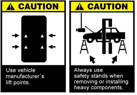
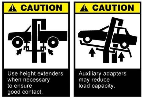
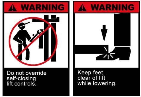
19 Only trained personnel should operate the lift. If not, it may cause danger to the inexperienced operator or the inexperienced operator may cause damage to the lift under improper manner. Only Authorized personnel should operate the lift. Persons that not be allowed should be away from the lift in case of danger appears. Make sure where the four points of the vehicle are to let the lift arms touch the four points properly. Safety stands shall be used under front and back end of the vehicle when removing or installing heavy components. Vehicle might incline or fall and cause injury if there are no safety stands under. If lifting arms can not touch the lifting points of the vehicle, select proper height extenders to the arm to reach the lifting points of the vehicle. Auxiliary tools, shelf for example, may reduce the load capacity of the lift. 19


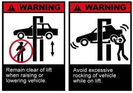
20 Should not lift the vehicle over the limited lifting height, which means the lift should stop the lifting activity when the vehicle touches the limit switch. If not, the vehicle will burst the crossbeam overhead. Keep feet clear of lift while the lift is lowering as it may injure the feet. There should be adequate space for personnel s escaping in case the vehicle is in danger of falling. Position vehicle with center of gravity midway between adapters. Otherwise the vehicle may loose its balance and fall. Personnel should be away from lift when it is raising and lowering to avoid possible injury. Do not rock the vehicle excessively while it is on lift. Vehicle may fall under violent rocking condition. 20
21 Percussion Drill Masonry Bit(16mm) Monkey Wrench (350mm) Crow Bar 21
22 Hammer Chalk Line Gradienter Flat Screwdriver Open-End Wrench Set(8mm ~ 25mm) Tape Measure(5m) Square Needle Nose Pliers CHARTPTER 4 TOOLS REQUIRED IMPORTANT NOTICE Do not attempt to install this lift if you have never been trained on basic automotive lift installation procedures. Never attempt to lift components without proper lifting tools such as forklift or cranes. Stay clear of any moving parts that can fall and cause injury. These instructions must be followed to ensure proper installation and operation of your lift. Failure to comply with these instructions can result in serious bodily harm and void product warranty. Manufacturer will assume no liability for loss or damage of any kind, expressed or implied resulting from improper installation or use of this product. PLEASE READ ENTIRE MANUAL PRIOR TO INSTALLATION. 22
23 CHARPTER 5 INSTALLATION STEPS 5.1 STEP 1 ( Selecting Site) Before installing your new lift, check the following: 1. LIFT LOCATION: Always use architects plans when available. Check layout dimension against floor plan requirements making sure that adequate space is available. 5m 4m 4m is recommended. 2. OVERHEAD OBSTRUCTIONS: The area where the lift will be located should be away from overhead obstructions such as heaters, building supports, electrical lines etc. 3. DEFECTIVE FLOOR: Visually inspect the site where the lift is to install and check for cracked or defective concrete. All models MUST be installed on 2500 PSI concrete (tension 200kg/cm2, thickness 300mm) only conforming to the minimum requirements shown above. New concrete must be adequately dried by at least 28 days. 4. Lift should be operated under condition with light not less than 300lux. 5. Noise is less than 75 db. "DO NOT install this lift on a second / elevated floor without first consulting building architect. "DO NOT install this lift outdoors unless special consideration has been made to protect the power unit from climate weather conditions. 5.2 STEP 2 ( Floor Requirements ) This lift must be installed on a solid, even concrete floor with less than 3-degrees of slope, consider a survey of the site and/or the possibility of pouring a new level concrete slab WARNING "DO NOT install this lift on any asphalt surface or any surface other than concrete. "DO NOT install this lift on expansion seams or on cracked or defective concrete. 23
 3.")
24 5.3 STEP 3 (Site Layout) 1. Determine which side will be the approach site. 2. Now determine which side you prefer the power unit to be located on. The POWERSIDE column has the power-unit mounting bracket attached to the side. (See diagram above for power unit location) 3. Once a location is determined, use a carpenter s chalk line to layout a grid for the post locations. Keep all dimensions and squareness within 1/8 or malfunctioning of the lift will occur After the post locations are properly marked, use a chalk or crayon to make an outline of the posts on the floor at each location using the post baseplates as a template Check all dimensions twice and make sure that the layout is perfectly correct. 6. Before continuing with the installation it is helpful to stand the posts up at their respective locations and get a visual of the shop, aisles and other clearances. Also, this is a good time to drive a vehicle into position and check for adequate clearance. After drilling, remove dust thoroughly out of each hole using compressed air and/or wire brush. Make certain that the column remains aligned with the chalk line during this process. Assemble the washers and nuts on the anchors then tap into each hole with a hammer until the washer rests against the baseplate. Be sure that if shimming is required that enough threads are left exposed. ( See Fig. 2 ) 5.4 STEP 4 ( Installing The POWERSIDE Column ) 1. Before proceeding, double check measurements and make certain that the bases of each column are square and in line with the chalk line Using the baseplate on the POWERSIDE column as a guide, drill each anchor hole on the concrete approximately 7-1/2 deep using a Percussion Drill and 3/4 concrete drill-bit. To assure full holding power, do not ream the hole or allow the drill to wobble. ( See Fig. 1 ) If shimming is required, insert the shims as necessary under the baseplate so that when the anchor bolts are tightened, the columns will be plumb. ( See Fig. 3 ) 24
Models PR-12F PR-12C PR-15C SURFACE MOUNTED TWO-POST LIFTS INSTALLATION AND OPERATION MANUAL
 Forward this manual to all operators. Failure to operate this equipment as directed may cause injury. INSTALLATION AND OPERATION MANUAL SURFACE MOUNTED TWO-POST LIFTS Models PR-12F PR-12C PR-15C Keep this
Models: SURFACE MOUNTED FOUR-POST LIFTS INSTALLATION AND OPERATION MANUAL
 Forward this manual to all operators. Failure to operate this equipment as directed may cause injury. INSTALLATION AND OPERATION MANUAL SURFACE MOUNTED FOUR-POST LIFTS Models: FL-18 BP-18 BP-27/ BP-27A
GLO-8000 SERIES (GLO-8000 & GLO-8000XLT)
") GLO-8000 SERIES (GLO-8000 & GLO-8000XLT) 8,000 LBS. CAPACITY FOUR-POST STORAGE LIFT INSTALLATION & OPERATION MANUAL SERIAL NUMBER: INSTALLATION DATE: EAGLE EQUIPMENT 1-800-336-2776 REV2011 03.0 BD SHIPPING
GLO-8000 SERIES (GLO-8000 & GLO-8000XLT) 8,000 LBS. CAPACITY FOUR-POST STORAGE LIFT INSTALLATION & OPERATION MANUAL SERIAL NUMBER: INSTALLATION DATE: EAGLE EQUIPMENT 1-800-336-2776 REV2011 03.0 BD SHIPPING
Model PL-7 / PL-7X AUTOMOBILE STACKER INSTALLATION AND OPERATION MANUAL
 Forward this manual to all operators. Failure to operate this equipment as directed may cause injury. AUTOMOBILE STACKER INSTALLATION AND OPERATION MANUAL Model PL-7 / PL-7X Keep this operation manual
GLO-7000 SERIES (GLO-7000 & GLO-7000XLT)
") GLO-7000 SERIES (GLO-7000 & GLO-7000XLT) 7,000 LBS. CAPACITY FOUR-POST STORAGE LIFT (BLUE) INSTALLATION & OPERATION MANUAL SERIAL NUMBER: INSTALLATION DATE: EAGLE EQUIPMENT 1-800-336-2776 (STANDARD) SHIPPING
GLO-7000 SERIES (GLO-7000 & GLO-7000XLT) 7,000 LBS. CAPACITY FOUR-POST STORAGE LIFT (BLUE) INSTALLATION & OPERATION MANUAL SERIAL NUMBER: INSTALLATION DATE: EAGLE EQUIPMENT 1-800-336-2776 (STANDARD) SHIPPING
ATTENTION. 1. Do not attempt to use the power unit to extend your cylinder. This must be done manually.
 NSS8XLT Installation Manual ATTENTION By following the instructions in this manual you can save yourself much time, frustration and money. The installation of your lift will take 4-5 hours. Do not rush.
FP-12L 12,000 LBS. CAPACITY FOUR-POST LIFT INSTALLATION & OPERATION MANUAL READ THIS MANUAL BEFORE INSTALLING OR OPERATING YOUR LIFT
 FP-12L 12,000 LBS. CAPACITY FOUR-POST LIFT INSTALLATION & OPERATION MANUAL READ THIS MANUAL BEFORE INSTALLING OR OPERATING YOUR LIFT REV 20160208.SUN01 BD INSPECT YOUR LIFT UPON DELIVERY. NOTE ANY DAMAGE
Read this entire manual before operation begins.
 Read this entire manual before operation begins. Record below the following information which is located on the serial number data plate. Serial No. Model No. Date of Installation Contents Specifications.............
Read this entire manual before operation begins.
 Read this entire manual before operation begins. Record below the following information which is located on the serial number data plate. Serial No. Model No. Date of Installation Contents Specifications.............
60 Watt Industrial LED Low Bay Light
 60 Watt Industrial LED Low Bay Light Owner s Manual WARNING: Read carefully and understand all ASSEMBLY AND OPERATION INSTRUCTIONS before operating. Failure to follow the safety rules and other basic safety
Read this entire manual before operation begins.
 Read this entire manual before operation begins. Record below the following information which is located on the serial number data plate. Serial No. Model No. Date of Installation Contents Specifications.............
INSTALLATION AND OPERATION MANUAL
 PLEASE READ THE ENTIRE CONTENTS OF THIS MANUAL PRIOR TO INSTALLATION AND OPERATION. BY PROCEEDING YOU AGREE THAT YOU FULLY UNDERSTAND AND COMPREHEND THE FULL CONTENTS OF THIS MANUAL. FORWARD THIS MANUAL
1000-lb Hydraulic Truck Crane
 1000-lb Hydraulic Truck Crane Owner s Manual WARNING: Read carefully and understand all ASSEMBLY AND OPERATION INSTRUCTIONS before operating. Failure to follow the safety rules and other basic safety precautions
Air-Operated Waste Oil Drainer
 Air-Operated Waste Oil Drainer 20-Gallon Tank Owner s Manual WARNING: Read carefully and understand all ASSEMBLY AND OPERATION INSTRUCTIONS before operating. Failure to follow the safety rules and other
150-Lb. Drywall and Panel Hoist
 150-Lb. Drywall and Panel Hoist Owner s Manual WARNING: Read carefully and understand all ASSEMBLY AND OPERATION INSTRUCTIONS before operating. Failure to follow the safety rules and other basic safety
Read this entire manual before operation begins.
 Read this entire manual before operation begins. Record below the following information which is located on the serial number data plate. Serial No. Model No. Date of Installation Contents Specifications.............
QJY245DS~DA. Two Post Lift Installation & Adjustment Manual
 QJY245DS~DA Two Post Lift Installation & Adjustment Manual Table of Contents 1. Warning 2 2. Summary 2 3. Use 2 4. Mainly technology parameter 2 5. Basic structure of the production 3 6. Safety device
Heavy-Duty Drywall Dolly Cart
 Heavy-Duty Drywall Dolly Cart Owner s Manual WARNING: Read carefully and understand all ASSEMBLY AND OPERATION INSTRUCTIONS before operating. Failure to follow the safety rules and other basic safety precautions
50 Ft. Retractable Cord Reel
 50 Ft. Retractable Cord Reel with Triple Tap Owner s Manual WARNING: Read carefully and understand all ASSEMBLY AND OPERATION INSTRUCTIONS before operating. Failure to follow the safety rules and other
Model FP12K-K Flat Deck Four-Post Lift
 Model FP12K-K Flat Deck Four-Post Lift (12,000LBS Capacity) ASSEMBLY & OPERATION INSTRUCTION 2006.4. TABLE OF CONTENTS Important Note--------------------------------------------------------------------------------Page
Electric Chainsaw Sharpener With Bar Mount
 Electric Chainsaw Sharpener With Bar Mount Owner s Manual WARNING: Read carefully and understand all ASSEMBLY AND OPERATION INSTRUCTIONS before operating. Failure to follow the safety rules and other basic
Angle Grinder Holder
 Angle Grinder Holder Owner s Manual WARNING: Read carefully and understand all ASSEMBLY AND OPERATION INSTRUCTIONS before operating. Failure to follow the safety rules and other basic safety precautions
DISC BRAKE CALIPER TOOL SET
 DISC BRAKE CALIPER TOOL SET 40732 ASSEMBLY AND OPERATING INSTRUCTIONS Diagrams within this manual may not be drawn proportionally. Due to continuing improvements, actual product may differ slightly from
Adjustable Steel Welding Table
 Adjustable Steel Welding Table Owner s Manual WARNING: Read carefully and understand all ASSEMBLY AND OPERATION INSTRUCTIONS before operating. Failure to follow the safety rules and other basic safety
4400-Lb. Capacity Pallet Jack
 Read carefully and understand all ASSEMBLY AND OPERATION INSTRUCTIONS before operating. Failure to follow the safety rules and other basic safety precautions may result in serious personal injury. Item#
16 Inch Surface Cleaner
 16 Inch Surface Cleaner Owner s Manual WARNING: Read and understand all instructions, warnings, and cautions before using this product. Failure to follow the instructions, warnings, and cautions may result
INSTALLATION AND OPERATION MANUAL 1,500 POUND CAPACITY MOTORCYCLE / ATV LIFT Model: RML-1500XL
 PLEASE READ THE ENTIRE CONTENTS OF THIS MANUAL PRIOR TO INSTALLATION AND OPERATION. BY PROCEEDING YOU AGREE THAT YOU FULLY UNDERSTAND AND COMPREHEND THE FULL CONTENTS OF THIS MANUAL. FORWARD THIS MANUAL
Sawhorse with Chainsaw Holder
 Sawhorse with Chainsaw Holder Owner s Manual Chainsaw not included. WARNING: Read carefully and understand all ASSEMBLY AND OPERATION INSTRUCTIONS before operating. Failure to follow the safety rules and
Hydraulic Bead Breaker Kit
 Hydraulic Bead Breaker Kit Owner s Manual WARNING: Read carefully and understand all ASSEMBLY AND OPERATION INSTRUCTIONS before operating. Failure to follow the safety rules and other basic safety precautions
ASSEMBLY & OPERATION INSTRUCTION MANUAL
 LR-26-PAD 6000 lb Capacity Low-Rise Pad Lift ASSEMBLY & OPERATION INSTRUCTION MANUAL 6,000 LB. LOW-RISE PAD LIFT Easy frame lifting on padded runways. Great for wheel and brake work, tire and wheel changing
INSTALLATION AND OPERATION MANUAL
 PLEASE READ THE ENTIRE CONTENTS OF THIS MANUAL PRIOR TO INSTALLATION AND OPERATION. BY PROCEEDING YOU AGREE THAT YOU FULLY UNDERSTAND AND COMPREHEND THE FULL CONTENTS OF THIS MANUAL. FORWARD THIS MANUAL
Model SL-12K-A SCISSOR LIFT. wheel alignment model. (11000 LBS / 5000Kg Capacity) INSTALLATION & OPERATION INSTRUCTION (SECOND EDITION)
 INSTALLATION & OPERATION INSTRUCTION (SECOND EDITION)") Model SL-12K-A SCISSOR LIFT wheel alignment model (11000 LBS / 5000Kg Capacity) INSTALLATION & OPERATION INSTRUCTION (SECOND EDITION) 2007. 6. CONTENTS Chapter 1 Introduction & Specifications ---------------------------------------
Model SL-12K-A SCISSOR LIFT wheel alignment model (11000 LBS / 5000Kg Capacity) INSTALLATION & OPERATION INSTRUCTION (SECOND EDITION) 2007. 6. CONTENTS Chapter 1 Introduction & Specifications ---------------------------------------
1200W Paint DRYING Lamp
 1200W Paint DRYING Lamp Model 97641 Assembly And Operation Instructions Diagrams within this manual may not be drawn proportionally. Due to continuing improvements, actual product may differ slightly from
12V Oil Extractor Pump
 12V Oil Extractor Pump Owner s Manual WARNING: Read carefully and understand all ASSEMBLY AND OPERATION INSTRUCTIONS before operating. Failure to follow the safety rules and other basic safety precautions
2000-lb Hand Winch Truck Crane
 2000-lb Hand Winch Truck Crane Owner s Manual WARNING: Read carefully and understand all ASSEMBLY AND OPERATION INSTRUCTIONS before operating. Failure to follow the safety rules and other basic safety
Air Curtain. Installation, Operating and Maintenance Instructions
 Installation, Operating and Maintenance Instructions Save this manual for future reference. Air Curtain Model Numbers: ES026, ES036, ES042, ES048, ES060, ES072 READ THIS OWNER S MANUAL CAREFULLY BEFORE
SPECIFICATIONS GENERAL SAFETY RULES PERSONAL SAFETY. Save This Manual TOOL USE AND CARE WORK AREA
 SPECIFICATIONS 2 Forged Safety Latch Hooks Cable extends to: 44 Drop forged steel hanging bracket Heavy duty 3/16 Steel Cable Pulling Capacity: 1200 LB. One piece double ratchet gear Save This Manual You
3-Pt. Quick Hitch. Owner s Manual
 3-Pt. Quick Hitch Owner s Manual WARNING: Read carefully and understand all ASSEMBLY AND OPERATION INSTRUCTIONS before operating. Failure to follow the safety rules and other basic safety precautions may
1250 LB. CAPACITY MECHANICAL WHEEL DOLLY
 1250 LB. CAPACITY MECHANICAL WHEEL DOLLY 67287 SET-UP AND OPERATING INSTRUCTIONS Visit our website at: http://www.harborfreight.com Read this material before using this product. Failure to do so can result
Read this entire manual before operation begins.
 Rev. 12/12/2017 Read this entire manual before operation begins. Record below the following information which is located on the serial number data plate. Serial No. Model No. Date of Installation Contents
Operating Instructions & Parts Manual. Fuel Tank Adapter
 Operating Instructions & Parts Manual Fuel Tank Adapter Model Number 40080 Capacity 80 lb.! This is the safety alert symbol. It is used to alert you to potential personal injury hazards. Obey all safety
Package Contents Part A (3) I-Beam (1) Base (2) Other parts
 I-Beam (1) Base (2) Other parts") Page 1 Installation Instructions for 81245 Adjustable Height Gantry Crane 1-Ton Capacity Table of Contents Important Safety Information pg. 2 Specific Operation Warnings pg. 2 Main Parts of Product pg.
Page 1 Installation Instructions for 81245 Adjustable Height Gantry Crane 1-Ton Capacity Table of Contents Important Safety Information pg. 2 Specific Operation Warnings pg. 2 Main Parts of Product pg.
Model FP14KO-A Wheel alignment & Open Front Four-Post Lift
 Model FP14KO-A Wheel alignment & Open Front Four-Post Lift ( 14000LBS / 6300Kg Capacity) ASSEMBLY & OPERATION INSTRUCTIONS ( Series T1) 2009.7. INTRODUCTION Model FP14KO-A is a four-post lift is used in
2-Pack Indoor Simulated Dome Security Cameras
 2-Pack Indoor Simulated Dome Security Cameras Owner s Manual WARNING: Read carefully and understand all ASSEMBLY AND OPERATION INSTRUCTIONS before operating. Failure to follow the safety rules and other
Large Hydraulic Bead Breaker
 Large Hydraulic Bead Breaker Owner s Manual WARNING: Read carefully and understand all ASSEMBLY AND OPERATION INSTRUCTIONS before operating. Failure to follow the safety rules and other basic safety precautions
Read this entire manual before operation begins.
 Read this entire manual before operation begins. Record below the following information which is located on the serial number data plate. Serial No. Model No. Date of Installation Contents Specifications.............
HOYMILES MICRO-IVERTER MI-250
 HOYMILES MICRO-IVERTER MI-250 TECHNICAL MANUAL CONTENTS INTRODUCTION... 3 SAFETY... 4 SYMBOL ILLUSTRATION... 4 INSTALLATION WARNINGS... 5 PREPARE FOR INSTALLING... 6 TRANSPORT AND INSPECT... 6 CHECK INSTALLATION
2000 lb Adjustable Gantry Crane
 2000 lb Adjustable Gantry Crane Owner s Manual WARNING: Read carefully and understand all ASSEMBLY AND OPERATION INSTRUCTIONS before operating. Failure to follow the safety rules and other basic safety
Heavy-Duty Welding Fabrication Table
 Heavy-Duty Welding Fabrication Table with Fix-Up Kit Owner s Manual WARNING: Read carefully and understand all ASSEMBLY AND OPERATION INSTRUCTIONS before operating. Failure to follow the safety rules and
4-LED Solar-Powered Pendant Shed Light
 4-LED Solar-Powered Pendant Shed Light Owner s Manual WARNING: Read carefully and understand all ASSEMBLY AND OPERATION INSTRUCTIONS before operating. Failure to follow the safety rules and other basic
Hydraulic Transmission Jacks
 Hydraulic Transmission Jacks Operating Instructions & Parts Manual Model Number Atd-7435 Atd-7436 Atd-7437 Capacity 1100 Lb. 2000 Lb. 3000 Lb. Model Atd-7435 Model Atd-7436 Model Atd-7437 Atd Tools Inc.
Atlas PV-9WP Addendum
 Atlas PV-9WP Addendum 9,000 lb. Capacity Two-Post Overhead Lift The Atlas PV-9WP above ground hoist is 6 inches wider than the Atlas PV-9P, giving it an overall width of 141 (11 9 ) and a drive thru width
Manual Chain Hoist. Owner s Manual
 Manual Chain Hoist Owner s Manual WARNING: Read carefully and understand all ASSEMBLY AND OPERATION INSTRUCTIONS before operating. Failure to follow the safety rules and other basic safety precautions
182-LED Solar-Powered Motion Security Light. Owner s Manual
 182-LED Solar-Powered Motion Security Light Owner s Manual WARNING: Read carefully and understand all ASSEMBLY AND OPERATION INSTRUCTIONS before operating. Failure to follow the safety rules and other
1000 lb. Adjustable Gantry Crane
 1000 lb. Adjustable Gantry Crane Owner s Manual WARNING: Read carefully and understand all ASSEMBLY AND OPERATION INSTRUCTIONS before operating. Failure to follow the safety rules and other basic safety
120-LED Solar-Powered Motion Security Light
 120-LED Solar-Powered Motion Security Light Owner s Manual WARNING: Read carefully and understand all ASSEMBLY AND OPERATION INSTRUCTIONS before operating. Failure to follow the safety rules and other
Hydraulic Drum Transporter
 Hydraulic Drum Transporter Owner s Manual WARNING: Read carefully and understand all ASSEMBLY AND OPERATION INSTRUCTIONS before operating. Failure to follow the safety rules and other basic safety precautions
RollSeal 1733 County Road 68 Bremen, Alabama Part No Rev Owner s Manual RS-Divider Curtain
 1. 2. 7 3. 4. RollSeal 1733 County Road 68 Bremen, Alabama 35033 256-287-7000 Part No 4801-5176 Rev 12-11-17 Owner s Manual RS-Divider Curtain Table of Contents 1 Warnings (Avertissements)... 3 2 Limited
3000-Lb. Vehicle Positioning Jacks. Owner s Manual
 3000-Lb. Vehicle Positioning Jacks Owner s Manual WARNING: Read carefully and understand all ASSEMBLY AND OPERATION INSTRUCTIONS before operating. Failure to follow the safety rules and other basic safety
Manual Tire Changing Station
 Manual Tire Changing Station Owner s Manual WARNING: Read carefully and understand all ASSEMBLY AND OPERATION INSTRUCTIONS before operating. Failure to follow the safety rules and other basic safety precautions
Garden Hose Reel with 3/4In. x 100Ft. Hose. Owner s Manual
 Garden Hose Reel with 3/4In. x 100Ft. Hose Owner s Manual WARNING: Read carefully and understand all ASSEMBLY AND OPERATION INSTRUCTIONS before operating. Failure to follow the safety rules and other basic
Dolly with Pneumatic Tires
 Dolly with Pneumatic Tires Owner s Manual WARNING: Read carefully and understand all ASSEMBLY AND OPERATION INSTRUCTIONS before operating. Failure to follow the safety rules and other basic safety precautions
SIDE-WIND, A-FRAME TRAILER JACK. Model Due to continuing improvements, actual product may differ slightly from the product described herein.
 SIDE-WIND, A-FRAME TRAILER JACK Model 95157 Assembly And Operation Instructions Due to continuing improvements, actual product may differ slightly from the product described herein. 3491 Mission Oaks Blvd.,
ATD Gallon Pressurized Oil Drain Owner s Manual
 ATD-5203 30 Gallon Pressurized Oil Drain Owner s Manual TECHNICAL SPECIFICATIONS Model: ATD-5203 Capacity: 30 Gallon Drain Funnel Working Height: 47.25 to 70.5 Drain Funnel Diameter: 15.75 Plastic Tray:
1000-LB. MOTORCYCLE LIFT TABLE OWNER S MANUAL
 1000-LB. MOTORCYCLE LIFT TABLE OWNER S MANUAL WARNING: Read carefully and understand all ASSEMBLY AND OPERATION INSTRUCTIONS before operating. Failure to follow the safety rules and other basic safety
Heavy-Duty Sawhorse. Owner s Manual
 Heavy-Duty Sawhorse Owner s Manual WARNING: Read carefully and understand all ASSEMBLY AND OPERATION INSTRUCTIONS before operating. Failure to follow the safety rules and other basic safety precautions
TWO POST LIFT. Operation Manual & Instruction STRONGMAN TOOLS LTD
 TWO POST LIFT USER S MANUAL Operation Manual & Instruction STRONGMAN TOOLS LTD 1 IMPORTANT SAFETY INSTRUCTIONS SAVE THESE INSTRUCTIONS PLEASE READ THE ENTIRE CONTENTS OF THIS MANUAL PRIOR TOINSTALLATION
Owner s Manual & Safety Instructions
 Owner s Manual & Safety Instructions Save This Manual Keep this manual for the safety warnings and precautions, assembly, operating, inspection, maintenance and cleaning procedures. Write the product s
(R86049) WARNING: To reduce the risk of injury, the user must read and understand the operator s manual before using this product.
 WARNING: To reduce the risk of injury, the user must read and understand the operator s manual before using this product.") OPERATOR S MANUAL 12 VOLT LITHIUM-ION BATTERY CHARGER 140446001 (R86049) Your charger has been engineered and manufactured to our high standards for dependability, ease of operation, and operator safety.
OPERATOR S MANUAL 12 VOLT LITHIUM-ION BATTERY CHARGER 140446001 (R86049) Your charger has been engineered and manufactured to our high standards for dependability, ease of operation, and operator safety.
VICE MOUNTED BEAD ROLLER
 VICE MOUNTED BEAD ROLLER Owner s Manual WARNING: Read carefully and understand all ASSEMBLY AND OPERATION INSTRUCTIONS before operating. Failure to follow the safety rules and other basic safety precautions
2-Pack Indoor/Outdoor Simulated Security Cameras. Owner s Manual
 2-Pack Indoor/Outdoor Simulated Security Cameras Owner s Manual WARNING: Read carefully and understand all ASSEMBLY AND OPERATION INSTRUCTIONS before operating. Failure to follow the safety rules and other
FLOOR JACK CROSS BEAM
 Please read and save these instructions. Read through this owner s manual carefully before using product. Protect yourself and others by observing all safety information, warnings, and cautions. Failure
110 Volt/12 Volt Portable Inflator
 110 Volt/12 Volt Portable Inflator Owner s Manual WARNING: Read carefully and understand all ASSEMBLY AND OPERATION INSTRUCTIONS before operating. Failure to follow the safety rules and other basic safety
USE AND MAINTENANCE MANUAL
 USE AND MAINTENANCE MANUAL TWO POST VEHICLE LIFT 2 IMPORTANT SAFETY INSTRUCTIONS SAVE THESE INSTRUCTIONS WARNING! PLEASE READ THE ENTIRE CONTENTS OF THIS MANUAL PRIOR TOINSTALLA- TION AND OPERATION. BY
before serial number 2214
 before serial number 2214 Contents Page Safety Rules... 3 Pre-operational & Safety Inspection... 4 Operating Instructions... 6 Transport... 12 Maintenance & Routine Service... 12 Specifications... 14 SAFETY
ATV Log Arch and Holder
 ATV Log Arch and Holder Owner s Manual WARNING: Read carefully and understand all ASSEMBLY AND OPERATION INSTRUCTIONS before operating. Failure to follow the safety rules and other basic safety precautions
55-Gallon Drum Cradle
 55-Gallon Drum Cradle Owner s Manual WARNING: Read carefully and understand all ASSEMBLY AND OPERATION INSTRUCTIONS before operating. Failure to follow the safety rules and other basic safety precautions
1000 Lb. Motorcycle Lift
 1000 Lb. Motorcycle Lift 91764 ASSEMBLY AND OPERATING INSTRUCTIONS Diagrams within this manual may not be drawn proportionally. Due to continuing improvements, actual product may differ slightly from the
Push Trolley. Owner s Manual
 Push Trolley Owner s Manual WARNING: Read carefully and understand all ASSEMBLY AND OPERATION INSTRUCTIONS before operating. Failure to follow the safety rules and other basic safety precautions may result
Hydro-Park High-end Four Post Parking Lift PROFESSIONAL PARKING SOLUTION PROVIDER!
 High-end Four Post Parking Lift PROFESSIONAL PARKING SOLUTION PROVIDER! Four Post Parking Lift 2 Levels Introduction is the new Four Post Parking Lift designed by Mutrade based on old FPP-2. It s a kind
INSTALLATION AND OPERATION MANUAL 14,000 POUND CAPACITY COMMERCIAL GRADE FOUR-POST LIFTS
 INSTALLATION AND OPERATION MANUAL 14,000 POUND CAPACITY COMMERCIAL GRADE FOUR-POST LIFTS MODELS: HDS-14 HDS-14X PLEASE READ THE ENTIRE CONTENTS OF THIS MANUAL PRIOR TO INSTALLATION AND OPERATION. BY PROCEEDING
will result in death or serious injury. could result in death or serious injury. Indicates a hazardous situation which, if not avoided,
 SAFETY SETUP OPERATION MAINTENANCE WARNING SYMBOLS AND DEFINITIONS This is the safety alert symbol. It is used to alert you to potential personal injury hazards. Obey all safety messages that follow this
p.t.o. Slip clutch Read this material before using this product. Failure to do so can result in serious injury. Save this manual.
 p.t.o. Slip clutch 65517 Installation Instructions Distributed exclusively by Harbor Freight Tools. 3491 Mission Oaks Blvd., Camarillo, CA 93011 Visit our website at: http://www.harborfreight.com Read
Single COB LED Solar-Powered Motion Security Light
 Single COB LED Solar-Powered Motion Security Light Owner s Manual WARNING: Read carefully and understand all ASSEMBLY AND OPERATION INSTRUCTIONS before operating. Failure to follow the safety rules and
Telescoping Pressure Washer Wand 18'
 Telescoping Pressure Washer Wand 18' Owner s Manual WARNING: Read carefully and understand all ASSEMBLY AND OPERATION INSTRUCTIONS before operating. Failure to follow the safety rules and other basic safety
Jema Autolifte A/S. Manual Release INSTALLTION, OPERATION AND MAINTENANCE MANUAL JA3500F ORIGINAL FOUR POST LIFT. Capacity: 3500KG
 Jema Autolifte A/S ORIGINAL JA3500F FOUR POST LIFT Capacity: 3500KG Manual Release INSTALLTION, OPERATION AND MAINTENANCE MANUAL Read this entire manual carefully and completely before installation and
OPERATOR S AND PARTS MANUAL PALLET FORKS. Part Number: MODEL NUMBER: Rev. 4
 OPERATOR S AND PARTS MANUAL PALLET FORKS SERIAL NUMBER: Manual Number: OM642 Part Number: 75542 MODEL NUMBER: Rev. 4 800-456-7100 I www.paladinlcg.com 503 Gay Street, Delhi, IA 52223, United States of
PUSH BUTTON KEY CABINET
 PUSH BUTTON KEY CABINET Model 95689 INSTALLATION And Operation Instructions Due to continuing improvements, actual product may differ slightly from the product described herein. 3491 Mission Oaks Blvd.,
2000-LB. ENGINE STAND
 2000-LB. ENGINE STAND WARNING: Read carefully and understand all ASSEMBLY AND OPERATION INSTRUCTIONS before operating. Failure to follow the safety rules and other basic safety precautions may result in
INSTALLATION & OPERATION MANUAL
 Two-Post Clear Floor Lift (Asymmetric) 9,000 lbs. Capacity (2,250 lbs. Max per Arm) INSTALLATION & OPERATION MANUAL IMPORTANT NOTES READ THE INSTALLATION AND OPERATION MANUAL IN ITS ENTIRETY BEFORE ATTEMPTING
Aluminum Plus Low Profile Service Jack
 Aluminum Plus Low Profile Service Jack Operating Instructions & Parts Manual Model Number ATD7344 ATD7345 Capacity 1.5 Ton 2.5 Ton Model ATD7344 Model ATD7345! This is the safety alert symbol. It is used
INSTALLATION GUIDE. Universal System for Zero Turn Mowers
 INSTALLATION GUIDE Universal System for Zero Turn Mowers Table of Contents General Information 1 Important Notice to Purchaser 2 Specifications 2 Intended Usage 2 Important Information 3 General Safety
CAMBELT TENSION GAUGE
 CAMBELT TENSION GAUGE Model 96557 Operating Instructions Diagrams within this manual may not be drawn proportionally. Due to continuing improvements, actual product may differ slightly from the product
1000-LB. ENGINE STAND
 1000-LB. ENGINE STAND WARNING: Read carefully and understand all ASSEMBLY AND OPERATION INSTRUCTIONS before operating. Failure to follow the safety rules and other basic safety precautions may result in
30 Inch x 18 Inch Service Cart
 30 Inch x 18 Inch Service Cart Owner s Manual WARNING: Read carefully and understand all ASSEMBLY AND OPERATION INSTRUCTIONS before operating. Failure to follow the safety rules and other basic safety
OWNER S MANUAL SELF-PRIMING PORTABLE UTILITY PUMP
 Model 54011-0 OWNER S MANUAL SELF-PRIMING PORTABLE UTILITY PUMP Questions, problems, missing parts? Before returning to the store call AQUAPRO Customer Service 8 a.m. - 5 p.m., EST, Monday-Friday 1-844-242-2475
Hydraulic Furniture Movers
 Hydraulic Furniture Movers Owner s Manual WARNING: Read carefully and understand all ASSEMBLY AND OPERATION INSTRUCTIONS before operating. Failure to follow the safety rules and other basic safety precautions
SUBMERSIBLE MINI-PUMP
 SUBMERSIBLE MINI-PUMP Model 41287 Set up And Operating Instructions Diagrams within this manual may not be drawn proportionally. Due to continuing improvements, actual product may differ slightly from
CONTENTS. Product Features and Specifications...1. Installation Requirement...3. Steps of Installation...4. Exploded View Test Run...
 TP10AS 2-POST LIFT CONTENTS Product Features and Specifications...1 Installation Requirement...3 Steps of Installation...4 Exploded View...24 Test Run....28 Operation Instruction...29 Maintenance...30
4QJY4.0-C & 4QJY4.0-C1 four post parking lift. Manual
 4QJY4.0-C & 4QJY4.0-C1 four post parking lift Manual Contents 1 Safety instruction and attentions.. 3 1.1 Cautions with words......3 1.2 Safety caution signal 4 1.3 Using Purpose.. 5 1.4 Expected Rated