OWNER S (OPERATOR S) MANUAL AND SAFETY INSTRUCTIONS FOR KITO MANUAL CHAIN HOIST CF SERIES
|
|
|
- Bryce Rose
- 5 years ago
- Views:
Transcription
 MANUAL AND SAFETY INSTRUCTIONS")
1 BULLETIN No. CF-9409-MCE-09 Original Instruction OWNER S (OPERATOR S) MANUAL AND SAFETY INSTRUCTIONS FOR KITO MANUAL CHAIN HOIST CF SERIES SAVE THIS BOOK FOR FUTURE REFERENCE.
2 CONTENTS 1. DEFINITIONS INTENDED PURPOSE MOUNTING BEFORE USE Safety summary Safety instructions MAIN SPECIFICATIONS OPERATION Intended purpose of hoist operation Safety working environment Operation Hoist storage INSPECTION Outline Daily inspection Periodic inspection MAINTENANCE Lubrication Overhaul, assembly and adjustment TROUBLESHOOTING WARRANTY PARTS LIST... 21

3 1. DEFINITIONS WARNING CAUTION : indicates a potentially hazardous situation which, if not avoided, could result in death or serious injury. : indicates a potentially hazardous situation which, if not avoided, may result in minor or moderate injury. It may also be used to alert against unsafe practices. WLL: indicate maximum mass (working load limit) which a hoist is designed to support in general service. 2. INTENDED PURPOSE This hoist has been designed for vertically lifting and lowering loads, by hand, under normal atmospheric conditions of the work place. 3. MOUNTING WARNING Avoid the following when mounting the chain hoist. Failure to comply with these instructions may result in death or severe injury. - Ensure that only trained or competent persons install the chain hoist. - Do not install the chain hoist within the range of movement of other devices (equipment), such as a trolley. Comply with the following instructions when installing the chain hoist. Failure to comply with these instructions may result in death or severe injury. - Check that the structure for mounting the chain hoist has sufficient strength. - Fix the Top Hook to the structure securely. - Before using the chain hoist with a trolley, read the Instruction Manual of the trolley carefully and install it by adjusting the rail width. - Install a stopper at both ends of the traversing rail for the trolley. 4. BEFORE USE 4.1 Safety summary Danger exists when heavy loads are transported, particularly when the equipment is not being used properly or is poorly maintained. Because accidents and serious injury could result, special safety precautions apply to the operation, maintenance and inspection of the KITO manual chain hoist CF series. WARNING use a hoist for lifting, supporting or transporting people. lift or transport loads over or near people. lift more than WLL which is shown on the name plate. OVER LORD 1

 people to operate the hoist.")
. check the brake (Refer to 7.3). oil the load chain regularly (Refer to 8.1.2).")
4 let people around you know when a lift is about to begin. read the operation and safety instructions. Remember proper rigging and lifting techniques are the responsibility of the operator. Check all applicable safety codes, regulations and other applicable laws for further information about the safe use of your hoist. More detailed safety information is contained in the following pages. For additional information, please contact KITO Corporation or your authorized KITO dealer. read safety instructions 4.2 Safety instructions WARNING Before use allow the instructed (trained in safety and operation) people to operate the hoist. check the hoist before daily use according to the Daily inspection (Refer to 7.2). make sure that the chain length is long enough for the intended job. check that the hook latches work properly and replace missing or broken hook latches (Refer to 7.3). check the brake (Refer to 7.3). oil the load chain regularly (Refer to 8.1.2). use two hoists which each has WLL equal to or more than the load to be lifted whenever you must use two hoists to lift a load. This will provide adequate protection in the event that a sudden load shift or failure of one hoist occurs. use a hoist without a hoist name plate. use modified or deformed hooks. use non-authentic chains on the hoist While operation make sure that the load is properly seated in the hook. tighten the slack out of the chain and sling when starting a lift to prevent a sudden loading. operate a hoist unless the load is centered under the hoist. use the hoist chain as a sling. 2

5 use a twisted, kinked, damaged or stretched load chain. swing a suspended load. support a load on the tip of the hook. contact the load chain over an edge. weld or cut a load suspended by a hoist. use the hoist chain as a welding electrode. operate a hoist so far that the bottom hook touches the hoist body. operate a hoist so far that the load chain pulls the anchorage. operate a hoist if excessive noise occurs. use the capsized load chain After operation set the load down safely after carrying. suspend a load for an extended period of time. leave a suspended load unattended. throw a hoist Maintenance let the qualified service personnel inspect the hoist periodically (Refer to 7.3). splice, add and weld a load chain for extension Others consult the manufacturer or your dealer if you plan to use a hoist in an excessively corrosive environment (salt water, sea air and/or acid, explosive environment or other corrosive compounds, etc.). use a hoist which has been taken out of service until the hoist has been properly repaired or replaced. remove or obscure the warning tags and labels. Warning tags are installed on a hand chain. 3
6 5. MAIN SPECIFICATIONS 0.5 to 1.5t 2t and 3t Code WLL (t) Std. lift (m) Min. distance between hooks: C (mm) Chain pull to lift full load (N) Chain o hauled to lift load *one meter (m) Test load (t) Net weight (kg) Load chain dia. (mm) x pitch (mm) Load chain fall (lines) Weight for additional one meter of lift (kg) CF x CF x CF x CF x CF x Remark: Any lift of chain is available on request. * Length of the hand chain necessary to lift a load 1m. Allowable ambient conditions Operation temperature : -40 C to +60 C Operation humidity : 100% Non-asbestos material; Friction plates are made of asbestos free material. a (mm) b (m) g (mm) 4
7 6. OPERATION 6.1 Intended purpose of hoist operation WARNING This hoist has been designed for vertically lifting and lowering loads, by hand, under normal atmospheric conditions of the work place. However, since dealing with heavy loads may involve unexpected danger, all the Safety instructions (Refer to 3.2) must be followed. 6.2 Safety working environment WARNING The operator must be aware of the following points while using the hoist. (1) The operator must have a clear and unobstructed view of the entire travel area before operating the hoist. When not possible, a second or more persons must serve as scouts in the nearby area. (2) The operator must check the entire travel area is safe and secure before operating the hoist. 6.3 Operation CAUTION take care hand or clothes not to be caught in a chain, idle sheave or other moving parts. (1) Face the hand chain wheel side of the hoist. (2) To raise the load, pull hand chain clockwise. (3) To lower the load, pull hand chain counterclockwise. (4) There are risks of overheating of the breaking system during prolonged lowering of loads. If you are considering of the use under such condition, consult KITO. Fig. 5-1 Hand wheel rotation Hand wheel Remark: The clicking sound of the pawl when a load is being raised indicates normal operation. 6.4 Hoist storage CAUTION Observe the following points when storing the hoist. store the hoist in no load condition. wipe off all dirt and water. oil the chain, top pin, chain pin and hook latches. hang in a dry place. Counterclockwise Clockwise check the hoist for abnormalities when using the hoist after a period of non-use according to the periodic inspection procedures (Refer to 6.3). 5
8 7. INSPECTION 7.1 Outline There are two types of inspection, the daily inspection performed by the operator before using the hoist, and the more thorough periodic inspection performed by qualified service personnel who have the authority to remove the hoist from service. 7.2 Daily inspection Before each work shift, check the following points; Item Inspection method Discard limit/criteria Remedy 1. Name plate Check visually. The name plate is attached and clearly Replace the name plate. legible. 2. Function 1) Lifting Pull the right hand chain, seen facing the wheel, to lift the load. The pawl makes a clicking sound while the chain is being taking up. Overhaul and service. 2) Lowering Pull the left hand chain, seen facing the wheel, to lower the load. The chain lowers, but the pawl does not make a clicking sound. Overhaul and service. 3. Hook latches Check visually. Top and bottom hook latches are in place and in proper condition. 4. Hook Check visually. Top and bottom hooks are not too wide. Replace the hook. Turn the swivels by hand. Shall turn smoothly. Replace the hook. 5. Load chain Check visually. No obvious rust or corrosion. Remove rust. Check visually. Lubrication must be on surface. Oil the load chain. Check visually No twists or harmful flaws Replace the load chain. 6. Miscellaneous Check visually. No missing nuts and/or split pins. Replace the parts. 6
9 7.3 Periodic inspection Periodic inspection should be made at the interval shown below and should follow the given procedures. NORMAL (Normal use): Semiannual inspection HEAVY (Frequent use): Quarterly inspection SEVERE (Excessively frequent use): Monthly inspection Figures in parentheses are Fig. No. in PARTS LIST. (Refer to page 22 to 23.) Item Inspection method Discard limit/criteria Remedy Name plate Check visually. WLL indication is clear. Attach the name plate. Hook [1, 4, 44, 56, 66, 75] (Top and bottom) 1. Deformation/ twist of hook opening Measure dimension c (shown in the next) at time of purchase with slide calipers. No deformation comparing with original shape (at time of purchase) Replace the hook. Check visually. Twist shall not be large enough to detect visually. Replace the hook. 2. Wear Measure a and b with slide calipers. use the hook if dimension a or b becomes less than 90% of normal. Replace the hook. WLL (t) a (mm) b (mm) Normal Discard Normal Discard Hook flaw Check visually. No great damage permitted. Replace the hook. 4. Hook movement Turn hook. Shall turn smoothly. Replace the hook. 7
10 Item Inspection method Discard limit/criteria Remedy 5. Top/bottom fixture damage [fittings of 1, 4, 44, 56, 66, 75] Check visually. No slack or missing rivets, nuts or bolts Replace the hook. 6. Idle sheave rotation [55, 61 70] Hold the load chain with both hands and turn the idle sheave by moving the chain up and down. Smooth rotation Overhaul. 7. Hook latch [2, 6, 45, 57, 67, 76] Check visually. Proper positioning and smooth working Replace the hook latch or hook. Load chain [42] 1. Wear Measure with slide One pitch calipers. Sum of pitches of five links Measure the sum of pitches of five chain links and check that the maximum length does not exceed the value shown in table below. WLL (t) Sum of pitches of five links (mm) Replace the chain. Discard limit (mm) , , Rust, flaw, deformation Check visually. No obvious rust (Apply oil as necessary.) Remove rust. No twist or harmful flaw. Replace the load chain. Hook yoke (Top set [1, 44, 66]) (Bottom set [4, 56, 75]) Joint of top/bottom fittings with top pin [3] and chain pin [7, 46] Measure hole diameter of joint area in two directions at right angle. Deformation not permitted (if each measured value differs more than 0.5mm). Function 1. Lifting and lowering Lift and lower a light load. No abnormal difficulty in lifting or lowering Overhaul and service. 8
11 Item Inspection method Discard limit/criteria Remedy 2. Brake function Lift and lower a light load. Confirm that none of the problems listed below occur during lifting and lowering. (1) Lifting is impossible. (2) Load falls when the operator removes his hands. (3) Load falls during unwinding. (4) Load slips down slowly. Overhaul and service. Brake parts Overhaul and check. Hand wheel [33] Friction plate [32] Bushing [31] Ratchet disc [30] Friction plate [32] Friction disc [29] Socket bolt [22-A] Wheel stopper [34] Split pin [36] Snap ring [28] Pawl [27] Wheel stopper pin [35] Pawl spring set [26] U nut [25] Pawl pin [24] Socket bolt [22] 1. Flaw on brake surface [31, 31-A, 32] Check visually. No flaw due to scratching or gouging by foreign matter 2. Wear on friction plate [32] Measure with side calipers. Retain uniform thickness and friction plates shall not be worn more than 0.5mm. For all types: Normal thickness: 3mm Discard limit: 2.5mm 9
![Item Inspection method Discard limit/criteria Remedy 3. Flatness of friction plate [32] Check clearance with straight gauge. Clearance shall be uniform.](/docs-images/96/127548636/images/12-0.jpg "Internal part shall not be thicker than external part. Internal Friction plate (37) (Discard condition) External 4.")
![Wear and oil of bushing [31] Check radial thickness (t) with slide caliper and oil existence. Radial thickness (t) shall be uniform. Oil shall be contained. Refer to table below.](/docs-images/96/127548636/images/12-2.jpg "Bushing [31] t: Radial thickness WLL (t) Normal thickness: t (mm) Discard limit (mm) 0.5 3 2 1, 1.5, 2, 3 4 3 5. Wear and rust of ratchet disc [30] Check visually.")
12 Item Inspection method Discard limit/criteria Remedy 3. Flatness of friction plate [32] Check clearance with straight gauge. Clearance shall be uniform. Internal part shall not be thicker than external part. Internal Friction plate (37) (Discard condition) External 4. Wear and oil of bushing [31] Check radial thickness (t) with slide caliper and oil existence. Radial thickness (t) shall be uniform. Oil shall be contained. Refer to table below. Bushing [31] t: Radial thickness WLL (t) Normal thickness: t (mm) Discard limit (mm) , 1.5, 2, Wear and rust of ratchet disc [30] Check visually. The tooth wear shall not be more than 1.5 mm. 6. Wear of pawl [27] Check visually. Pawl tip wear is not found. 7. Deformation and rust of pawl spring A, B [26] Check visually. No bend or deformation No rust permitted Lifting system 1. Wear and deformation of load sheave [18] Check visually. No large wear, no deformation or no burr due to load chain contact is permitted on the surface of load chain pocket. Load chain pocket Load sheave [18] 10
13 Item Inspection method Discard limit/criteria Remedy 2. Wear and flaw of pinion [14] and load gear [19] Check visually. Teeth shall be free from large wear or flaw. Ball bearing B [16] Body B [11] Pinion [14] Frame [13] Load gear [19] Ball bearing C [17] 3. Wear and deformation of hand wheel [33] Check visually. No large wear or no deformation on the surface of hand chain pocket Turn and check if it touches the cover. Frame [13] 1. Flaw on frame Check visually. No flaw or crack Replace the frame. Miscellaneous 1.Wear on chain guide [20] Check visually. No excessive wear or press mark is permitted. 2. Flaw on guide roller [20-A] Check visually. Shall turn lightly. Check visually. No large deformation. 3. Deformation of stripper [21] Check visually. No large crush or damage on stripper tip is permitted. 4. Deformation of tail pin [40] Check visually. No large deformation 11
14 8. MAINTENANCE WARNING (1) perform maintenance on the hoist while it is supporting a load. (2) Before performing maintenance, attach the tag; [ DANGER : OPERATE EQUIPMENT BEING REPAIRED.] (3) Only allow qualified service personnel to perform maintenance. (4) After performing any maintenance on the hoist, test to WLL before returning to service. CAUTION take care hand or clothes not to be caught in a chain, idle sheave or other moving parts. 8.1 Lubrication Applying grease to gear Remove body B (11) in the way of 8.2 Overhaul (Refer to page 13 and 14). Remove old grease and replace with new grease (standard grease (1) ), at annual inspection. Temperature range of standard grease is -40 C to +60 C. If the hoist is used at temperature below -40 C or above +60 C, consult the manufacturer or dealer since some parts shall be changed. Note: (1) Calcium soap grease equivalent of NLGI (National Lubricating Grease Institute)/# Load chain WARNING Failure to maintain clean and well lubricated load chain will void the manufacturer s warranty. lubricate load chain weekly, or more frequently, depending on severity of service. lubricate more frequently than normal in a corrosive environment. (2) use machine oil equivalent to ISO VG46 or 68. Note: (2) KITO has a corrosion-resistant chain as an option. For information of KITO s regular and corrosion-resistant chain, please ask your dealer. 12
15 8.2 Overhaul, assembly and adjustment Overhaul Figures in parentheses are Fig. No. in PARTS LIST. (Refer to page 22 and 23.) Overhaul procedures Remarks 1. Put a hoist with wheel cover side up. 2. Unscrew three nuts [38] (with the spring washers [39]) fixing the wheel cover [37]. 3. Remove the wheel cover [37] from the body A [10]. 4. Insert the standing link of the hand chain [43] into the notch of the hand wheel [33] and remove the hand chain by turning the hand wheel counterclockwise. 5. Pull out the split pin [36] from the wheel stopper pin [35] and remove the wheel stopper pin and the wheel stopper [34] from the pinion [14]. 6. Remove the hand wheel [33] from the pinion [14] by turning the hand wheel counterclockwise. 7. Remove two friction plates [32], the ratchet disc [30] and the bushing [31] from the friction disc [29]. 8. Remove the friction disk [29] from the pinion [14] by turning counterclockwise holding the end of the pinion with fingers. 9. Remove the snap ring [28] from the pawl pin [24] (on the side plate A [10]) and then remove the pawl [27] and pawl spring set [26]. Bring the notch of the hand wheel to the right hand. If the hand wheel is too tight to turn by hand, put the hand chain on the hand wheel back again and pull it down hard. It will release the brake. 10. Unscrew the pawl pin [24]. The pawl pin is fixed with the U nut [25]. 11. Unscrew four socket bolts [22, 22-A] connecting body A [10] and B [11]. Four socket bolts are fixed with U nuts [23] on the body B side. 12. Separate the body A [10] and B [11]. 13. Take ball bearing A [15] and C [17-A] out of the body A [10]. Remove the bearing by tapping the ball bearing A and C with a wooden hammer from the brake side. 14. Remove top hook [1] and top pin [3] from the body B [11]. 13
16 Overhaul procedures Remarks 15. Remove pinion [14], chain guide [20] (or guide rollers [20-A]), stripper [21], tail pin [40], and load chain [42]. 16. Remove the frame [13]. 17. Take load sheave [18] out of the load gear [19]. 18. Remove the load gear [19]. 19. Unscrew tap socket bolt [41] from the body B [11]. 20. Pull the split pin [9] out of the slotted nut [8] and remove the slotted nut and chain pin [7] from the bottom hook [4] Assembly and adjustment Assembly procedures Remarks 1. Wipe off old grease from the body B [11] and frame [13]. 2. Apply new grease to the ball bearing B [16] and C [17] on the body B [11]. 3. Insert load sheave [18] into the load gear [19] and put them together on the ball bearing C [17]. Body B [11] Ball bearing B [16] Load sheave [18] Load gear [19] 4. Apply new grease to the load gear [19]. 5. Put frame [13] on the body B [11] according to pattern. 6. Insert the end of the load chain [42] to the bottom hook [4] and fix them with the chain pin [7], slotted nut [8] and split pin [9]. CAUTION bend the split pin securely. 14
17 Assembly procedures Remarks Load chain [42] Chain pin [7] Bottom hook [4] Slotted nut [8] Split pin [9] 7. Wind load chain [42] round the load sheave [18] so that the bottom hook side comes to right hand and the end link of the other side becomes standing to the load sheave pocket. CAUTION Put the welded part of the standing chain link outward. Frame [13] Body B [11] Load sheave [18] Welded part of standing link Load chain [42] No load side To bottom hook 8. Put chain guide [20] (or guide rollers for 0.5t [20-A]) on the frame [13]. 9. Put stripper [21] on the frame [13]. Fit the larger boss of chain guide [20] into holes on frame [13]. 10. Insert pinion [14] shaft from its gear side into the frame [13]. 11. Insert top pin [3] into the frame [13] and put top hook [1] to the top pin. 15
18 Assembly procedures Remarks Top hook [1] Top pin [3] Pinion [14] Chain guide [20] Load sheave [18] Stripper [21] Load chain [42] No load side To bottom hook 12. Grease ball bearing A [15] and insert it into the body A [10]. 13. Put the body A [10] with the ball bearings [15, 17-A] side down on the body B [11]. 14. Insert four socket bolts [22, 22-A] into the body A [10] and turn the whole body sideways. Then fix the bolts with the U nuts [23] holding the U nuts with fingers. Make sure each part is completely set between body A [10] and frame [13]. Insert short socket bolts [22-A] to the upper holes and long socket bolts [22] to the lower holes. Socket bolts [22-A] Body B [11] Body A [10] Socket bolt [22] U nut [23] 16
19 Assembly procedures 15. Insert pawl pin [24] into the body A [10] and fix it with the U nut [25]. 16. Apply machine oil to the pawl pin [24] and join pawl spring A, B [26] and the pawl [27] respectively to it. Fix the pawl with snap ring [28]. 17. Put friction disc [29] to the pinion [14]. 18. Wipe our any dirt on the friction disc [29], friction plates [32] and both sides of the ratchet disc [30] and check that bushing [31] contains oil soaked inside. Then place the friction plate, bushing, ratchet disc (while turning the pawl [27] counterclockwise) and friction plate respectively on the friction disc. (Make sure that the pawl meshes with the ratchet disc properly.) Snap ring [28] Pawl spring set Pawl [27] Socket bolt [22-A] Remarks Make sure the pawl spring is fixed to the pawl and the snap ring is securely set at the groove of the pawl pin. apply oil since the brake is dry-type. Wipe out thoroughly any oil and dirt on the brake. The gear of the ratchet disc shall point at the pawl. Otherwise, the hand wheel cannot be assembled later. In case the bushing does not have oil inside, soak it in tarbin oil for a day. Install it in without wiping the oil. Make sure that the pawl meshes with the ratchet disc properly. Pawl pin [24] Friction disc [29] Friction plate [32] Ratchet disc [30] Pinion [14] Body A [10] Socket bolt [22] 19. Wipe out the dirt of the hand wheel [33] and apply machine oil to the threaded part of it. Screw it in the pinion [14] shaft all the way down. 20. Place the wheel stopper [34] on the head of the pinion [14], insert the wheel stopper pin [35] and fix it with a split pin [36]. bend the split pin securely after inserting into the wheel stopper pin. 17
20 Assembly procedures Remarks 21. Set the notch of the hand wheel to the left hand. Insert the standing link of the hand chain [43] into the notch of the hand wheel [33] and reeve the hand chain by turning the hand wheel clockwise. Wheel stopper [34] Wheel stopper pin [35] Notch Pinion [14] Hand wheel [33] Split pin [36] Hand chain [43] 22. Put wheel cover [37] on the body A [10] and fix them with the spring washers [39] and screws [38]. 23. Put a hoist with body B [11] side up. Place the slack end of the load chain between body A [10] and body B [11]. Then insert tail pin [40], and screw tap socket bolt [41] into the body B. Make sure the load chain is not twisted. Tap socket bolt [41] Tail pin [40] Body B [11] Body A [10] Stripper [21] Load chain [42] Hand wheel [33] 18
21 9. TROUBLESHOOTING Situation Cause Explanation Remedy The pawl makes the proper clicking sound but fails to lift the load. Worn friction plates When used at high frequency without performing maintenance regularly, the friction plates will wear down. This will create gaps between the friction disc, bushing and hand wheel, and cause the brake to slip. Disassemble and replace the friction plates and bushing. The pawl produces absolutely no sound and fails to lift the load. The pawl has been improperly assembled. The pawl is not moving smoothly. If the pawl is assembled facing the other way, or otherwise assembled incorrectly, it will not cleanly mesh with the ratchet disc. Unless maintenance is performed regularly, dirt will adhere to the grease on the pawl and pawl shaft. Movement will become sluggish and the pawl will remain stuck in the kicked out position. Disassemble and then reassemble parts correctly. Same as above The chain is tight when lifting, even without a load. (A squeaking noise can be heard at times.) Worn load gear teeth Worn or damaged bearing. Unless maintenance is performed regularly, greased parts will dry, resulting in wear and damage, and improper meshing of gears. Disassemble and replace the pinion, load gear, body B, frame and ball bearing. Improper lowering or the chain is extremely tight when lowering. The brake is too tight. Due to shock during work, or because the load was left suspended for a long period of time, the brake tightened. Free the brake forcibly by jerking the hand chain. The brake is rusted. Unless maintenance is performed regularly, rusting will occur. Disassemble and replace parts where necessary. The hoist drops the load the instant lowering is started. The braking surface is dirty. During assembly, the braking surface must be wiped cleaned of dirt. Disassemble and then reassemble parts correctly. The braking surface is oily. The braking surface must not be allowed to become soiled with grease or machine oil because it is a dry-type brake. Disassemble and then reassemble parts. Do not oil or grease the braking surface or friction plates. Load slipping The braking surface is oily. Same as above Same as above The braking surface is dirty. During assembly, the braking surface must be wiped cleaned of dirt. Disassemble and then reassemble parts correctly. 19
22 10. WARRANTY KITO Corporation ( KITO ) extends the following warranty to the original purchaser ( Purchaser ) of new products manufactured by KITO (KITO s Products). (1) KITO warrants that KITO s Products, when shipped, shall be free from defects in workmanship and/or materials under normal use and service and KITO shall, at the election of KITO, repair or replace free of charge any parts or items which are proven to have said defects, provided that all claims for defects under this warranty shall be made in writing immediately upon discovery and, in any event, within one (1) year from the date of purchase of KITO s Products by Purchaser and provided, further, that defective parts or items shall be kept for examination by KITO or its authorized agents or returned to KITO s factory or authorized service center upon request by KITO. (2) KITO does not warrant components of products provided by other manufacturers. However to the extent possible, KITO will assign to Purchaser applicable warranties of such other manufacturers. (3) Except for the repair or replacement mentioned in (1) above which is KITO s sole liability and purchaser s exclusive remedy under this warranty. KITO shall not be responsible for any other claims arising out of the purchase and use of KITO s Products, regardless of whether Purchacer s claims are based on breach of contract, tort or other theories, including claims for any damages whether direct, indirect, incidental or consequential. (4) This warranty is conditional upon the installation, maintenance and use of KITO s Products pursuant to the product manuals prepared in accordance with content instructions by KITO. This warranty shall not apply to KITO s Products which have been subject to negligence, misuse, abuse, misapplication or any improper use or combination or improper fittings, alignment or maintenance. (5) KITO shall not be responsible for any loss or damage caused by transportation, prolonged or improper storage or normal wear and tear of KITO s Products or for loss of operating time. (6) This warranty shall not apply to KITO s products which have been fitted with or repaired with parts, components or items not supplied or approved by KITO or which have been modified or altered. THIS WARRANTY IS IN LIEU OF ALL OTHER WARRANTIES, EXPRESS OR IMPLIED, INCLUDING BUT NOT LIMITTED TO ANY WARRANTY OF MERCHANTABILITY OR OF FITNESS FOR A PARTICULAR PURPOSE. 20
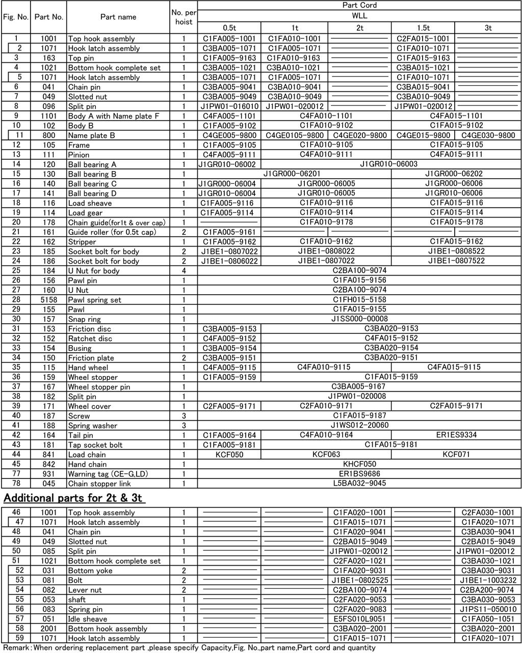
23 11. PARTS LIST 21
24 22
25 23
26 D/C CF-1207-E-02-OM CONTENTS OF EC DECLARATION OF CONFORMITY We, KITO Corporation, 2000, Tsuijiarai, Showa-cho, Nakakoma-gun, Yamanashi, , Japan declare under our sole responsibility that the products: Hand chain operated chain hoist in capacity range of 500 kg up to 3 tonnes, CF, model CF4 to which this declaration relates is in conformity with the following EC directives and standards. EC directives: Machinery Directive Harmonized standards: EN ISO 12100: 2010 EN 818-7: A1: 2008 EN 13157: A1: /42/EC Risk assessment and risk reduction Short link chain for lifting purposes, increased quality, grade V, certified by Fachausschuss Metall und Oberflächenbehandlung Hand powered cranes Authorized representative for the arrangement of the technical documents: Udo Kleinevoß Technical Manager Kito Europe GmbH Düsseldorf A08-02-OM
27
28 URL. KITO Europe GmbH Heerdter Lohweg 93, D Düsseldorf, Germany TEL: +49-(0) FAX: +49-(0) URL: KITO corporation Tokyo Head office: SHINJUKU NS Building 9F, 2-4-1, Nishi-Shinjuku, Shinjuku-ku, Tokyo , Japan Head office & Factory: 2000 Tsuijiarai Showa-Cho, Nakakoma-Gun, Yamanashi , Japan URL:
Owner s (Operator s) Manual & Safety Instructions Manually Lever Operated Chain Hoist Model LX1B
 Manual & Safety Instructions Manually Lever Operated Chain Hoist Model LX1B") Owner s (Operator s) Manual & Safety Instructions Manually Lever Operated Chain Hoist Model LX1B BULLETIN NO. LX-0804-CE-06 WARNING This equipment must not be installed, operated or maintained by any person
Owner s (Operator s) Manual & Safety Instructions Manually Lever Operated Chain Hoist Model LX1B BULLETIN NO. LX-0804-CE-06 WARNING This equipment must not be installed, operated or maintained by any person
OWNER S (OPERATOR S) MANUAL AND SAFETY INSTRUCTIONS FOR KITO PLAIN AND GEARED TROLLEY TS SERIES
 MANUAL AND SAFETY INSTRUCTIONS FOR KITO PLAIN AND GEARED TROLLEY TS SERIES") OM-TSZZZZ-CEE-01D Original Instruction OWNER S (OPERATOR S) MANUAL AND SAFETY INSTRUCTIONS FOR KITO PLAIN AND GEARED TROLLEY TS SERIES ALWAYS SAVE THIS BOOK FOR FUTURE REFERENCE. ssued September 1994.
OM-TSZZZZ-CEE-01D Original Instruction OWNER S (OPERATOR S) MANUAL AND SAFETY INSTRUCTIONS FOR KITO PLAIN AND GEARED TROLLEY TS SERIES ALWAYS SAVE THIS BOOK FOR FUTURE REFERENCE. ssued September 1994.
Before equipment use, please read this operation manual carefully. Serial Number: Date Purchased:
 Pushed & Geared Trolleys OPERATION MANUAL This operation manual is intended as an instruction manual for trained personnel who are in charge of installation, maintenance, repair etc. Before equipment use,
LX1 Inspection Manual for Model LX1B. Table of contents 1. INSPECTION CLASSIFICATION DAILY INSPECTION FREQUENT INSPECTION...
 KTI KITO Technical Information LX1 Inspection Manual for Model LX1B LX1-1.1.1 1 / 9 Edition: C 03.06 Table of contents 1. INSPECTION CLASSIFICATION...2 2. DAILY INSPECTION...3 3. FREQUENT INSPECTION...3
1/2-TON MANUAL CHAIN HOIST
 1/2-TON MANUAL CHAIN HOIST Owner s Manual WARNING: Read carefully and understand all ASSEMBLY AND OPERATION INSTRUCTIONS before operating. Failure to follow the safety rules and other basic safety precautions
TONS. Before each shift: Before operating: Before initial operation of hoist:
 LEVER HOIST 0.25 9 TONS Manual Notice It is the responsibility of the owner/user to install, inspect, test, maintain, and operate these lever hoists in accordance with ASME B30.21, Safety Standard for
Capacity (tonnes) 0.25t. No. of Falls 1. Load Chain (mm) Load Chain Grade 80
 0.25t. No. of Falls 1. Load Chain (mm) Load Chain Grade 80") Capacity (tonnes) Model NO. 0.25t K025 No. of Falls Load Chain (mm) 4 2 Load Chain Grade 80 Pull To Lift Rated Load (N) Test load (tonnes) Hand Chain (mm) Std. lift (ft) Net. Weight (lbs) Gross. Weight
Capacity (tonnes) Model NO. 0.25t K025 No. of Falls Load Chain (mm) 4 2 Load Chain Grade 80 Pull To Lift Rated Load (N) Test load (tonnes) Hand Chain (mm) Std. lift (ft) Net. Weight (lbs) Gross. Weight
LX MINI PULLER OWNER S MANUAL 1/4 and 1/2 Ton Capacities Effective: May 19, 2017
 LX MINI PULLER OWNER S MANUAL 1/4 and 1/2 Ton Capacities Effective: May 19, 2017 WARNING This equipment should not be installed, operated or maintained by any person who has not read and understood all
Owner s Manual MANUAL CHAIN HOIST CF SERIES
 EFFECTIVE: December 4, 2007 Owner s Manual MANUAL CHAIN HOIST CF SERIES MODEL CF4 1/2 Ton through 5 Ton Capacity Code, Lot and Serial Number WARNING This equipment should not be installed, operated or
OPERATIONS MANUAL LEVER CHAIN HOIST
 OPERATIONS MANUAL LEVER CHAIN HOIST IMPORTANT SAFETY INFORMATION Please read, understand and follow all safety information contained in these instructions prior to the use of this hoist. Retain these instructions
MANUAL CHAIN HOIST CF SERIES
 EFFECTIVE: April 7, 2017 MANUAL CHAIN HOIST CF SERIES MODEL CF4 1/2 Ton through 5 Ton Capacity Code, Lot and Serial Number This equipment should not be installed, operated or maintained by any person who
MANUAL CHAIN HOIST CB SERIES
 EFFECTIVE: January 16, 2017 MANUAL CHAIN HOIST CB SERIES MODEL M3 1/2 Ton through 20 Ton Capacity Code, Lot and Serial Number This equipment should not be installed, operated or maintained by any person
Provided by: Operating, Maintenance & Parts Manual
 Provided by: www.hoistsdirect.com TB681.qxd 11/29/2004 3:04 PM Page 1 Operating, Maintenance & Parts Manual TB603 Manually Lever Operated Chain Hoist 1100 POUNDS MAXIMUM CAPACITY (500 kg) Follow all instructions
Lincoln Hoist. Web Hoist Operating Manual. Lincoln Hoist
 Lincoln Hoist Web Hoist Operating Manual Lincoln Hoist Mfg. by Lincoln Precision Machining Company 121 Creeper Hill Road, P.O. Box 458, North Grafton, MA 01536 USA Toll Free (888) 306-7222 Phone (774)
MANUAL CHAIN HOIST CF SERIES
 EFFECTIVE: October 8, 2014 MANUAL CHAIN HOIST CF SERIES MODEL CF4 1/2 Ton through 5 Ton Capacity Code, Lot and Serial Number This equipment should not be installed, operated or maintained by any person
Hand Chain Hoists. Before equipment use, please read this operation manual carefully. Serial Number: Date Purchased:
 Hand Chain Hoists OPERATION MANUAL This operation manual is intended as an instruction manual for trained personnel who are in charge of installation, maintenance, repair etc. Before equipment use, please
OPERATOR S MANUAL LEVER HOIST 0.75 TON 1.5 TON 3 TON. These Lever Hoists meet or exceed the following standards: CE ANSI B30.21
 OPERATOR S MANUAL LEVER HOIST 0.75 TON 1.5 TON 3 TON These Lever Hoists meet or exceed the following standards: CE ANSI B30.21 pg.1 P.O. Box 845, Winona, MN 55987 Phone (800) 749-1064 (507) 474-6250 Tech
Lineman s Hoist. Operating, Maintenance & Parts Manual. Follow all instructions and warnings for LMST680-2
 Lineman s Hoist LMST0- Operating, Maintenance & Parts Manual Lineman s Hoist Follow all instructions and warnings for inspecting, maintaining and operating this hoist. The use of any hoist presents some
OPERATOR S MANUAL CARBON STEEL & STAINLESS STEEL BRAKE WINCHES CARBON STEEL: OZ1000BW OZ1500BW OZ2000BW
 OPERATOR S MANUAL CARBON STEEL & STAINLESS STEEL BRAKE WINCHES Working Loads: 1000 lbs. 1500 lbs. 2000 lbs. Please read the Owner s Manual carefully before operating the equipment. Keep this manual nearby
CX HAND CHAIN HOIST OWNER S MANUAL ¼ Ton and ½ Ton Capacity Effective: May 9, 2017
 CX HAND CHAIN HOIST OWNER S MANUAL ¼ Ton and ½ Ton Capacity Effective: May 9, 2017 WARNING This equipment should not be installed, operated or maintained by any person who has not read and understood all
Manual Chain Hoist. Owner s Manual
 Manual Chain Hoist Owner s Manual WARNING: Read carefully and understand all ASSEMBLY AND OPERATION INSTRUCTIONS before operating. Failure to follow the safety rules and other basic safety precautions
NAVY TROLLEY HOIST. MODEL NTH 1 Ton through 5 Ton Capacity. Code, Lot and Serial Number
 EFFECTIVE: March 17, 2008 NAVY TROLLEY HOIST MODEL NTH 1 Ton through 5 Ton Capacity Code, Lot and Serial Number This equipment should not be installed, operated or maintained by any person who has not
OPERATION SERVICE PARTS TUGIT2. Manually Operated Short Handle Lever Hoist A3140-XXX
 OPERATION SERVICE PARTS TUGIT2 Manually Operated Short Handle Lever Hoist A3140-XXX Sold & Serviced by Morgan Aero 1450 80 th Street SW Everett WA U.S.A. 425/438.9600 SAFETY PRECAUTIONS WARNING! Improper
Owner s Manual & Safety Instructions
 Owner s Manual & Safety Instructions Save This Manual Keep this manual for the safety warnings and precautions, assembly, operating, inspection, maintenance and cleaning procedures. Write the product s
Serial. Operation & Maintenance Manual. Models: X5SL02250, X5SL03528, X5SL07056, X5SL14000 & X5SL20000
 TM AMH Model Operation & Maintenance Manual Models: X5SL02250, X5SL03528, X5SL07056, X5SL14000 & X5SL20000 READ THIS MANUAL BEFORE USING THESE PRODUCTS. This manual contains important safety, installation
Mini Lever Hoist. Owner s Manual
 Mini Lever Hoist Owner s Manual WARNING: Read carefully and understand all ASSEMBLY AND OPERATION INSTRUCTIONS before operating. Failure to follow the safety rules and other basic safety precautions may
DeZURIK 2 20" BOS BUTTERFLY VALVES
 2 20" BOS BUTTERFLY VALVES Instruction D10459 October 2013 2-20 BOS Butterfly Valves Instructions These instructions provide information about BOS Butterfly Valves. They are for use by personnel who are
BULLETIN NO.CX-1108-MG-00
 BULLETIN NO.CX-1108-MG-00 This equipment should not be installed,operated or maintained by any person who has not read and understood all the contents of this manual. Failure to read and comply with the
.JET. JTP Series Pullers OWNER1S MANUAL E~IPMENT & TOOLS. JET EQUIPMENT & TOOLS, INC. A WMH Company
 -- - -- --.JET E~IPMENT & TOOLS OWNERS MANUAL JTP Series Pullers JET EQUIPMENT & TOOLS, INC. A WMH Company www.jettools.com P.o. BOX 349 Auburn, WA 9807-349 e-mail jet@jettools.com Phone:53-35-6000 Fax:
OPERATOR S MANUAL CHAIN HOIST 0.25 TON 0.5 TON 1 TON 2 TON. These Hand Chain Hoists meet or exceed the following standards: CE ANSI B30.
 OPERATOR S MANUAL CHAIN HOIST 0.25 TON 0.5 TON 1 TON 2 TON These Hand Chain Hoists meet or exceed the following standards: CE ANSI B30.16 P.O. Box 845, Winona, MN 55987 Phone (800) 749-1064 (507) 474-6250
Operating Instructions For Your LUG-ALL Cable Winch-Hoist
 LAC-0108 Rev. 5/08 Operating Instructions For Your LUG-ALL Cable Winch-Hoist 604 Hemlock Road, Morgantown, PA 19543 Phone: (877) 658-4255 / Fax: (610) 286-9661 / Web: www.lug-all.com Copyright 2008 LUG-ALL
Owner s Manual. MODEL L5 3/4 Ton through 9 Ton Capacity. Code, Lot and Serial Number WARNING
 EFFECTIVE: October 12, 2007 Owner s Manual LEVER OPERATED CHAIN HOIST LB SERIES MODEL L5 3/4 Ton through 9 Ton Capacity Code, Lot and Serial Number WARNING This equipment should not be installed, operated
Rev. 10/27/2015 CDL-2000, MANUAL
 VESTIL MANUFACTURING CORP. 2999 North Wayne Street, P.O. Box 507, Angola, IN 46703 Telephone: (260) 665-7586 Toll Free (800) 348-0868 Fax: (260) 665-1339 www.vestilmfg.com e-mail: sales@vestil.com CDL-2000
MODEL SHB 1 Ton through 10 Ton Capacity. Code, Lot and Serial Number
 EFFECTIVE: September 13, 2017 MANUAL TROLLEY HOIST MODEL SHB 1 Ton through 10 Ton Capacity Code, Lot and Serial Number This equipment should not be installed, operated or maintained by any person who has
1000-lb Hydraulic Truck Crane
 1000-lb Hydraulic Truck Crane Owner s Manual WARNING: Read carefully and understand all ASSEMBLY AND OPERATION INSTRUCTIONS before operating. Failure to follow the safety rules and other basic safety precautions
Owner s Manual & Safety Instructions
 Owner s Manual & Safety Instructions Save This Manual Keep this manual for the safety warnings and precautions, assembly, operating, inspection, maintenance and cleaning procedures. Write the product s
Morgan Aero Products. AP7108 PNEUMATIC POWERED FISHPOLE HOIST Operation, Maintenance & Part s Rev. O - 01/01/13
 AP7108 PNEUMATIC POWERED FISHPOLE HOIST Operation, Maintenance & Part s Rev. O - 01/01/13 Morgan Aero Products 1450 80 th Street SW - Everett, WA - 425-438-9600 FORWARD This manual has been written to
MG12K24T60V4 Mechanical Grapple
 170 State Route 271 Attachment Solutions MG12K24T60V4 Mechanical Grapple Operators Manual KENCO Mechanical Grapple Operation Manual 1 TABLE OF CONTENTS 170 State Route 271 Section I. General Information....
Distributed by Tri-State Equipment Company Inc. Web: PH: FAX:
 Lineman s Hoist Distributed by Tri-State Equipment Company Inc. Email: sales@tsoverheadcrane.com Web: www.tsoverheadcrane.com PH: -869-00 FAX: -869-6 LMST680 Operating, Maintenance & Parts Manual Lineman
PARTS, OPERATION AND MAINTENANCE MANUAL
 Form MHD56028 PARTS, OPERATION AND MAINTENANCE MANUAL for MANUAL CHAIN HOIST MODELS MCH5-005 MCH5-010 MCH5-015 1/2 ton 1 ton 1-1/2 ton MCH5-020 MCH5-030 MCH5-050 2 ton 3 ton 5 ton Unless otherwise noted,
OPERATOR S MANUAL LEVER HOIST 0.75 TON THROUGH 9 TON. These Lever Hoists meet or exceed the following standards: CE AS ANSI B30.21 ANSI B30.
 OPERATOR S MANUAL LEVER HOIST 0.75 TON THROUGH 9 TON These Lever Hoists meet or exceed the following standards: CE AS1418.2 ANSI B30.21 ANSI B30.16 pg.1 P.O. Box 845, Winona, MN 55987 Phone (800) 749-1064
Owner s Manual. MODEL L5 3/4 Ton through 9 Ton Capacity. Code, Lot and Serial Number WARNING
 EFFECTIVE: May 15, 2008 Owner s Manual LEVER OPERATED CHAIN HOIST LB SERIES MODEL L5 3/4 Ton through 9 Ton Capacity Code, Lot and Serial Number WARNING This equipment should not be installed, operated
Hydraulic Transmission Jacks
 Hydraulic Transmission Jacks Operating Instructions & Parts Manual Model Number Atd-7435 Atd-7436 Atd-7437 Capacity 1100 Lb. 2000 Lb. 3000 Lb. Model Atd-7435 Model Atd-7436 Model Atd-7437 Atd Tools Inc.
1000 lb. Adjustable Gantry Crane
 1000 lb. Adjustable Gantry Crane Owner s Manual WARNING: Read carefully and understand all ASSEMBLY AND OPERATION INSTRUCTIONS before operating. Failure to follow the safety rules and other basic safety
Disassembly and Reassembly Manual
 AS No.ER2-0908-MC-00 ER2 Series Electric Chain Hoist (125kg to 5t) Disassembly and Reassembly Manual Safety precaution This Disassembly and Reassembly Manual includes contents to prevent injury to any
OPERATION SERVICE PARTS Manually Operated Lever Hoist
 OPERATION SERVICE PARTS Manually Operated Lever Hoist With 21 Handle A3134-XXX A3191-XXX A3192-XXX MA8196-XXX (with special attachments) MA8206-XXX (with special attachments) A3195-XXX MA8195-XXX (with
APCO CRF-100A RUBBER FLAPPER SWING CHECK VALVES
 APCO CRF-100A RUBBER FLAPPER SWING CHECK VALVES Instruction D12043 June 2016 DeZURIK Instructions These instructions provide installation, operation and maintenance information for APCO CRF-100A Rubber
2000 lb Adjustable Gantry Crane
 2000 lb Adjustable Gantry Crane Owner s Manual WARNING: Read carefully and understand all ASSEMBLY AND OPERATION INSTRUCTIONS before operating. Failure to follow the safety rules and other basic safety
2000-lb Hand Winch Truck Crane
 2000-lb Hand Winch Truck Crane Owner s Manual WARNING: Read carefully and understand all ASSEMBLY AND OPERATION INSTRUCTIONS before operating. Failure to follow the safety rules and other basic safety
Giant Hydraulic Disc Brake System
 Giant Hydraulic Disc Brake System INSTALLATION INSTRUCTI IMPORTANT NOTICE Contact the place of purchase or Authorized Giant Retailer for information on detail of installation and maintenance. Read this
HOIST ARMY TYPE HOIST IMPORTANT
 AA-93 15 SECTION AT/A/15 Service Instructions and Maintenance Manual 18:i!ii il HOIST ARMY TYPE HOIST IMPORTANT Keep for Future Reference SERVICE INSTRUCTIONS AND MAINTENANCE MANUAL 1 METRIC TON CAUTION:
SPECIFICATIONS GENERAL SAFETY RULES PERSONAL SAFETY. Save This Manual TOOL USE AND CARE WORK AREA
 SPECIFICATIONS 2 Forged Safety Latch Hooks Cable extends to: 44 Drop forged steel hanging bracket Heavy duty 3/16 Steel Cable Pulling Capacity: 1200 LB. One piece double ratchet gear Save This Manual You
CHESTER HOIST AIR LOW HEADROOM CHAIN HOISTS AL-680 SECTION A
 CHESTER HOIST AIR LOW HEADROOM CHAIN HOISTS AL-680 SECTION A OPERATING and MAINTENANCE INSTRUCTIONS FOR AL SERIES HOISTS Users should refer to the ANSI B30.16 American National Standard and ASME HST-5M
LUBRICATOR GUN INSTRUCTIONS-PARTS LIST. 10,000 psi (700 bar) Maximum Delivery Pressure. Detachable-type
 Maximum Delivery Pressure. Detachable-type") INSTRUCTIONS-PARTS LIST 306 460 INSTRUCTIONS This manual contains important warnings and information. READ AND KEEP FOR REFERENCE. Rev. E Supercedes D Detachable-type LUBRICATOR GUN 10,000 psi (700 bar)
INSTRUCTIONS-PARTS LIST 306 460 INSTRUCTIONS This manual contains important warnings and information. READ AND KEEP FOR REFERENCE. Rev. E Supercedes D Detachable-type LUBRICATOR GUN 10,000 psi (700 bar)
HOOK-BASE INSTRUCTION MANUAL
 VESTIL MANUFACTURING CORP. 2999 North Wayne Street, P.O. Box 507, Angola, IN 46703 Telephone: (260) 665-7586 -or- Toll Free (800) 348-0868 Fax: (260) 665-339 www.vestilmfg.com e-mail: sales@vestil.com
6-TON DOUBLE LOCKING JACK STANDS OWNER S MANUAL
 6-TON DOUBLE LOCKING JACK STANDS OWNER S MANUAL WARNING: Read carefully and understand all ASSEMBLY AND OPERATION INSTRUCTIONS before operating. Failure to follow the safety rules and other basic safety
2000-Lb. Adjustable Gantry Crane
 2000-Lb. Adjustable Gantry Crane Owner s Manual WARNING: Read carefully and understand all ASSEMBLY AND OPERATION INSTRUCTIONS before operating. Failure to follow the safety rules and other basic safety
Operating Instructions and Parts Manual JLP-A Series Manual Lever Hoists/Pullers 1/4- to 6-Ton
 Operating Instructions and Parts Manual JLP-A Series Manual Lever Hoists/Pullers 1/4- to 6-Ton JLP-025A 1/4-ton JLP-150A 1-1/2-ton (models shown are representative of the series) JET 427 New Sanford Road
Heavy Duty Engine Cranes
 Heavy Duty Engine Cranes Operating Instructions & Parts Manual Model Number Atd-7484 Atd-7485 (Foldable Legs) Capacity 2 Ton 2 Ton Model Atd-7484 Model Atd-7485 Atd Tools Inc. 160 Enterprise Drive, Wentzville,
Package Contents Part A (3) I-Beam (1) Base (2) Other parts
 I-Beam (1) Base (2) Other parts") Page 1 Installation Instructions for 81245 Adjustable Height Gantry Crane 1-Ton Capacity Table of Contents Important Safety Information pg. 2 Specific Operation Warnings pg. 2 Main Parts of Product pg.
Page 1 Installation Instructions for 81245 Adjustable Height Gantry Crane 1-Ton Capacity Table of Contents Important Safety Information pg. 2 Specific Operation Warnings pg. 2 Main Parts of Product pg.
OVERHEAD & GANTRY CRANE / RIGGING
 Overhead & Gantry Crane / Rigging OVERHEAD & GANTRY CRANE / RIGGING Overhead and gantry cranes - 1910.179 Crawler locomotive and truck cranes. - 1910.180 Slings. 1910.184 Cranes, like all pieces of heavy
PAGE 1 OF 5 HEALTH, SAFETY & ENVIRONMENTAL MANUAL PROCEDURE: S360 Overhead Cranes & Lifts Procedure REV 4.0 8/14/2012
 PAGE 1 OF 5 PURPOSE: OVERHEAD CRANES AND LIFTS PROCEDURE The purpose of this procedure is to define the safety and training requirements for use of overhead cranes and lifts. Procedure: Definitions Designated
1000-LB. MOTORCYCLE LIFT TABLE OWNER S MANUAL
 1000-LB. MOTORCYCLE LIFT TABLE OWNER S MANUAL WARNING: Read carefully and understand all ASSEMBLY AND OPERATION INSTRUCTIONS before operating. Failure to follow the safety rules and other basic safety
Distributed by Kincrome Group
 CHAIN BLOCK Distributed by Kincrome Group www.kincromegroup.com Owner s Assembly and Operating Manual SPECIFICATIONS...2 IMPORTANT SAFETY INFORMATION...3 GETTING STARTED...3 Unpacking Carton...3 Positioning
JIB-FM Series Floor Mounted Jib Cranes Instruction Manual
 VESTIL MANUFACTURING CORP. 2999 North Wayne Street, P.O. Box 507, Angola, IN 46703 Telephone: (260) 665-7586 -or- Toll Free (800) 348-0868 Fax: (260) 665-1339 www.vestilmfg.com e-mail: HUsales@vestil.comU
3-TON DOUBLE LOCKING JACK STANDS OWNER S MANUAL
 3-TON DOUBLE LOCKING JACK STANDS OWNER S MANUAL WARNING: Read carefully and understand all ASSEMBLY AND OPERATION INSTRUCTIONS before operating. Failure to follow the safety rules and other basic safety
CRP-series Carpet Rams Instruction Manual
 Vestil Manufacturing Corp. 2999 North Wayne Street, P.O. Box 507, Angola, IN 46703 Telephone: (260) 665-7586 -or- Toll Free (800) 348-0868 Fax: (260) 665-1339 Web: www.vestilmfg.com e-mail: info@vestil.com
4000-Lb. Adjustable Gantry Crane
 4000-Lb. Adjustable Gantry Crane Owner s Manual WARNING: Read carefully and understand all ASSEMBLY AND OPERATION INSTRUCTIONS before operating. Failure to follow the safety rules and other basic safety
Gauge Adapter Instruction Manual
 Instruction Manual MODELS: CF3812, CF3812E, CF3814 & CF4514 CF3812-M1_092017! This is the safety alert symbol. It is used to alert you to potential personal injury hazards. Obey all safety messages that
BELOW-THE-HOOK & MATERIAL HANDLING EQUIPMENT
 BELOW-THE-HOOK & MATERIAL HANDLING EQUIPMENT lifting EQUIPMENT Tongs HBTF Bar Tong Fixed... Page 62 TONGS HBTA Bar Tong Adjustable... Page 63 lifting EQUIPMENT HBTF BAR TONG FIXED FEATURES This style of
DeZURIK 24" THRU 36" RESILIENT BUTTERFLY VALVES
 24" THRU 36" RESILIENT BUTTERFLY VALVES Instruction D10348 April 2015 Instructions These instructions provide information about DeZURIK 24" thru 36" Resilient Butterfly Valves. They are for use by personnel
CRF-SERIES CARPET POLES INSTRUCTION MANUAL
 VESTIL MANUFACTURING CORP. 2999 North Wayne Street, P.O. Box 507, Angola, IN 46703 Telephone: (260) 665-7586 -or- Toll Free (800) 348-0868 Fax: (260) 665-1339 www.vestilmfg.com e-mail: sales@vestil.com
Operating Instructions & Parts Manual. Fuel Tank Adapter
 Operating Instructions & Parts Manual Fuel Tank Adapter Model Number 40080 Capacity 80 lb.! This is the safety alert symbol. It is used to alert you to potential personal injury hazards. Obey all safety
46761-E OPERATING, MAINTENANCE & PARTS MANUAL SUPPLEMENT ARMY TYPE TROLLEY HOIST
 OPERATING, MAINTENANCE & PARTS MANUAL SUPPLEMENT ARMY TYPE TROLLEY HOIST Distributed by Tri-State Equipment Company Inc. Email: sales@tsoverheadcrane.com Web: www.tsoverheadcrane.com PH: 3-69-700 FAX:
SBRL-SERIES SPREADER BEAMS INSTRUCTION MANUAL
 VESTIL MANUFACTURING CORP. 2999 North Wayne Street, P.O. Box 507, Angola, IN 46703 Telephone: (260) 665-7586 -or- Toll Free (800) 348-0868 Fax: (260) 665-1339 www.vestilmfg.com e-mail: info@vestil.com
Operating Instructions & Parts Manual
 Forklift Jack Operating Instructions & Parts Manual Model Number HW93659 Capacity 4 Ton Made in the U.S.A.! This is the safety alert symbol. It is used to alert you to potential personal injury hazards.
PARTS, OPERATION AND MAINTENANCE MANUAL for MANUAL CHAIN HOIST MODELS VL2-005 VL2-010 VL2-015 VL2-020 VL2-030 VL2-050 VL2-080 VL2-100 VL2-150 VL2-200
 Form MHD56012 PARTS, OPERATION AND MAINTENANCE MANUAL for MANUAL CHAIN HOIST MODELS VL2-005 VL2-010 VL2-015 VL2-020 VL2-030 1/2 ton 1 ton 1-1/2 ton 2 ton 3 ton VL2-050 VL2-080 VL2-100 VL2-150 VL2-200 5
Air Actuated Hydraulic Bottle Jacks
 Air Actuated Hydraulic Bottle Jacks Operating Instructions & Parts Manual Model Number Atd-7412 Atd-7420 Capacity 12 Ton 20 Ton Atd Tools Inc. 160 Enterprise Drive, Wentzville MO 63385 Printed in China
te. OPERATING AND HAND CHAIN HOIST MAINTENANCE INSTRUCTIONS IMPORTANT CAUTION
 Tffigif te. OPERATING AND HAND CHAIN HOIST MAINTENANCE INSTRUCTIONS WITH PARTS LIST PUBLICATION NO. LMHA-680 LMHA SERIES IMPORTANT CAUTION This manual contains important information for the correct installation,
4. MAINTENANCE MANUAL
 4. MAINTENANCE MANUAL 4.1 INTRODUCTION The maintenance program has been developed by ORIENTAL in accordance to our supplier s own maintenance program for each component. Conforming to this maintenance
TECHNICAL SERVICE MANUAL
 Electronic copies of the most current TSM issue can be found on the Viking Pump website at www.vikingcom TECHNICAL SERVICE MANUAL abrasive liquid pumps SERIES 4625 SIZES f - fh SECTION TSM 410.1 PAGE 1
PRODUCT OBSOLETED 4Q16
 Electronic copies of the most current TSM issue can be found on the Viking Pump website at www.vikingcom TECHNICAL SERVICE MANUAL abrasive liquid pumps SERIES 4625 SIZES f - fh SECTION TSM 410.1 PAGE 1
LAD-series Portable Warehouse Ladders, 6-12 Steps Instruction Manual
 Rev. 3/3/07 LAD (6- STEPS), MANUAL VESTIL MANUFACTURING CORP. 999 North Wayne Street, P.O. Box 507, Angola, IN 46703 Telephone: (60) 665-7586 -or- Toll Free (800) 348-0868 Fax: (60) 665-339 www.vestilmfg.com
1250 LB. CAPACITY MECHANICAL WHEEL DOLLY
 1250 LB. CAPACITY MECHANICAL WHEEL DOLLY 67287 SET-UP AND OPERATING INSTRUCTIONS Visit our website at: http://www.harborfreight.com Read this material before using this product. Failure to do so can result
APCO CSV-1600 SURGE CHECK VALVE
 APCO CSV-1600 SURGE CHECK VALVE Instruction D12022 January 2013 Instructions These instructions provide installation, operation and maintenance information for APCO CSV-1600 Surge Check Valves. They are
Instruction for use. POWERTEX Chain Block model PCB-S1
 GB Instruction for use POWERTEX Chain Block model PCB-S1 1 POWERTEX Chain Block PCB-S1 0.25 10 tonnes Instruction for use (GB) (Original instructions) Read through these user instructions carefully before
ELECTRIC CHAIN HOIST OPERATOR S MANUAL. 440 lbs Capacity 20 Feet Lifting Height 12.5 FPM Lifting Speed ANSI B30.16
 OPERATOR S MANUAL ELECTRIC CHAIN HOIST 440 lbs Capacity 20 Feet Lifting Height 12.5 FPM Lifting Speed ANSI B30.16 pg.1 P.O. Box 845, Winona, MN 55987 Phone (800) 749-1064 (507) 474-6250 Tech Support (507)
AC Electric Capstan Owner s Manual Installation and Operating Instructions
 AC Electric Capstan Owner s Manual Installation and Operating Instructions Model: HD2000-1A34-F-01 Serial Number: 123456 VAC _ Ø Hz Line Size: 1/2 CAUTION The final determination as to the suitability
AP6108 FISHPOLE HOIST
 AP6108 FISHPOLE HOIST Operation, Maintenance & Part s Rev. 02/01/2013 for SN CXXXX hoists only Morgan Aero Products 1450 80 th Street SW - Everett, WA - 425-438-9600 FORWARD This manual has been written
Fitting Instruction for EZI-GRIP Bike Rack
 Fitting Instruction for EZI-GRIP Bike Rack Congratulations on purchasing Ezi-Grip to carry your valued bicycles. We are sure you will get many years of enjoyable use from your Ezi-Grip Bike Rack. These
Manifold w/ Needle Valve Instruction Manual
 MODELS: MFC2 & MFC4 Manifold w/ Needle Valve Instruction Manual SFA Companies 10939 N. Pomona Ave. Kansas City, MO 64153 Tel: 888-332-6419 - Fax: 816-448-2142 E-mail: sales@bvahydraulics.com Website: www.bvahydraulics.com
LAD-EZ Series Portable Warehouse Ladders, 6-12 Steps Assembly Manual
 Rev. 3/3/07 LAD-EZ (6- STEPS), MANUAL Vestil Manufacturing Corp. 999 North Wayne Street, P.O. Box 507, Angola, IN 46703 Telephone: (60) 665-7586 -or- Toll Free (800) 348-0868 Fax: (60) 665-339 www.vestilmfg.com
Material Handling - Cranes, Hoists, Slings, Chain Falls, and Ratchet Hoists
 Material Handling - Cranes, Hoists, Slings, Chain Falls, and Ratchet Hoists University Facilities Internal Procedure: July 1, 2013 Effective date: July 1, 2013 Last Modified: April 2013 Approved by: Bob
ALULIFT Portable Aluminium Gantry Crane Operation & Maintenance Instructions
 ALULIFT Portable Aluminium Gantry Crane Tel: +44 (0)115 932 7010 Fax: +44 (0)115 9306263 Email: sales@metreel.co.uk Website: www.metreel.co.uk CONTENTS Caution...3 Pre-Build Check List...4 Initial Set
Clevis Plunger & Base Instruction Manual
 MODELS: CED09 & CED16 SFA Companies 10939 N. Pomona Ave. Kansas City, MO 64153 Tel: 888-332-6419 - Fax: 816-448-2142 E-mail: sales@bvahydraulics.com Website: www.bvahydraulics.com CED09-M0_102017 Clevis
BELOW-THE-HOOK & MATERIAL HANDLING EQUIPMENT
 BELOW-THE-HOOK & MATERIAL HANDLING EQUIPMENT lifting EQUIPMENT HRLB ROLL LIFTING BEAM...Page 44 HMRL MOTORIZED ROLL LIFTER...Page 45 HRGT ROLL GRIPPING TONGS...Page 46 HRLCH ROLL LIFTING C-HOOK...Page
DeZURIK 24 and Larger BHP High Performance Butterfly Valves WITH (FB) FYRE-BLOCK SEAT
 FYRE-BLOCK SEAT") 24 and Larger BHP High Performance Butterfly Valves WITH (FB) FYRE-BLOCK SEAT Instruction D10497 April 2015 BHP High Performance Butterfly Valves (S2, S3, S5, AA, HC, ML, T2 & T5 Shafts) Instructions These
24 and Larger BHP High Performance Butterfly Valves WITH (FB) FYRE-BLOCK SEAT Instruction D10497 April 2015 BHP High Performance Butterfly Valves (S2, S3, S5, AA, HC, ML, T2 & T5 Shafts) Instructions These
MODEL BARE REEL SERIES E
 MODEL 84275 BARE REEL SERIES E SPECIFICATIONS Maximum working pressure 5000 p.s.i. Material Inlet 1/2 NPT (Female) Material outlet 1/2 NPT (Female) Sheave width 10 Sheave diameter 19-1/4 Drum diameter
Heavy Duty Four Wheeled Walker
 Heavy Duty Four Wheeled Walker Weight Capacity: 500 lbs. ITEM # W1802 Made in China 2011 ESSENTIAL MEDICAL SUPPLY, INC. Manufactured for Orlando, FL 32822 -- SAVE THESE INSTRUCTIONS -- Do not attempt to
Hydraulic Clutch Jack
 Hydraulic Clutch Jack Operating Instructions & Parts Manual Model Number Atd-7404 Capacity 500 Lb. Atd Tools Inc. 160 Enterprise Drive, Wentzville MO 63385 Printed in China ATD7404-M0 05/07 Save these