OPERATION AND MAINTENANCE MANUAL
|
|
|
- Roger Joseph
- 5 years ago
- Views:
Transcription

 255-8366 Brea, California 92821 www.")

1 L10031 Rev-K OPERATION AND MAINTENANCE MANUAL SONIC 200 / 200C Sonic Air Systems, Inc. Phone: (714) Beacon Street Fax: (714) Brea, California Saving Energy Worldwide...one PSI at a time TM Copyright 2017-Sonic Air Systems Inc.
2 Table of Contents 1 Sonic 200 / Sonic 200C Introduction Introduction Typical Applications Initial Inspection Safety Instructions Electrical Mechanical Installation and Adjustments Lifting and Handling Blower Location Access Temperature Moisture and Debris Wash Down Explosive Environments Corrosive Environments Vibration Water Cooling Circuit Thermocouple Option Belt Installation Tools Required Belt Installation Procedure Blower Head Mounting Adjustment Required Tools Blower Head Adjustment Procedure Electrical Wiring, and Start-Up Motor Wiring Blower Specifications Blower Specification Sheet Assembly Drawing Parts List Sonic 200 Blower Unit Sonic 200C Blower Unit Motor Reference Nema Motor Specifications Periodic Maintance Maintenance Schedule Torque Specifications Belt Replacement Procedure Tools Required Belt Replacement Procedure Belt Tensioner Service Tools Required Belt Tensioner Service Procedure Bearing Cartridge Replacement Procedure Assembly Drawing Page i
3 7.5.2 Bearing Cartridge Assembly Parts List Required Tools Bearing Cartridge Replacement Procedure Recommended Spares Retro Kit Installation ( Assemble Sonic Drive to existing motor) Tools Required Retro Kit Installation Troubleshooting Performance Guarantee Warranty Policy /7/365 Service Program Sonic Repair Policy Page ii
4 Table of Figures Figure 1 - Sonic 200C (Front View)... 1 Figure 2 - Sonic 200C (Back View)... 1 Figure 3 - Sonic Nameplate... 2 Figure 4 Blower Serial Number... 3 Figure 5 - Lifting Point... 4 Figure 6 - Remove Belt Guard... 7 Figure 7 - Install Belt... 7 Figure 8 Adjust Belt Gap... 7 Figure 9 Install Belt... 7 Figure 10 Adjust Belt Gap... 7 Figure 11 Verify Belt Gap... 7 Figure 12 - Blower Rotations... 8 Figure 13 - Remove Belt Guard... 9 Figure 14 Remove Belt... 9 Figure 15 Disconnect Water-Cooling Lines... 9 Figure 16 Remove Blower Head... 9 Figure 17 Move Water-Cooling Plugs... 9 Figure 18 - Reinstall Blower Heads... 9 Figure 19 Reconnect Water-Cooling Lines Figure 20 Reinstall Belt Figure 21 Verify Belt Gap Figure 22 - Adjust Belt Gap Figure 23 - Remove Belt Guard Figure 24 - Install New Belt Figure 25 - Set Belt Gap to ¾ inch Figure 26 - Adjust Gap Figure 27 - Remove Belt Guard Figure 28 Remove Belt Figure 29 Verify Belt Gap Figure 30 Adjust Belt Gap Figure 31 - Remove Belt Guard Figure 32 Remove Filter or Inlet Screen Figure 33 - Remove Belt Figure 34 Remove Cover Figure 35 Remove Water Cooling Tubing Figure 36 Remove Impeller Figure 37 - Remove Blower Pulley Figure 38 - Remove Bearing Cartridge Hardware Figure 39 - Remove Thermocouple Figure 40 - Remove Bearing Cartridge Figure 41 - Remove Compression Fitting Figure 42 - Blower w/ Bearing Cartridge Removed Figure 43 - Installed Uni-mount Figure 44 - Mount Bracket to Motor Figure 45-Prepare Bushing Figure 46-Installed Bushing Figure 47-Install Bushing Hardware Figure 48-Bushing Installation Figure 49-Installed Set Screw Figure 50-Installed Motor Pulley Figure 51-Installed Belt Figure 52-Set Belt Gap to ¾ Figure 53-Check Alignment Figure 54-Install Belt Guard Page iii


5 1 Sonic 200 / Sonic 200C Introduction Figure 1 - Sonic 200C (Front View) Figure 2 - Sonic 200C (Back View) 1.1 Introduction Thank you for the recent purchase of a Sonic 200 or Sonic 200C centrifugal blower or retro-kit. Sonic Air Systems is confident that the blower unit is the best available in this performance range. Sonic manufactures blowers using the finest components available, assembles using only highly trained and qualified personnel, and inspects each unit 100% for quality and performance. The following manual is intended to: Identify safety hazards Familiarize personnel with the equipment performance Demonstrate typical installation and usage Identify maintenance schedule and typical spare components Provide Sonics Performance Guarantee and Warranty information 1.2 Typical Applications The following is a list of typical applications for using a Sonic 200 centrifugal blower assembly. This is only a partial list of the possible uses for supplying low cost, clean air to a particular application. Please consult a Sonic Application engineer to design a system to meet any request. Parts drying Hydrocarbon vapor recovery Gas boosting Concrete grinding vacuum Cooling Oil spill containment booms Engine exhaust sampling Environmental test chambers Tank / Pond aeration Gas meter testing Vacuum hold down Air bearings Special applications and options are available for the Sonic 200 blower unit: Corrosion resistant electroplating Air flow control valves 316 Stainless Steel Material Option Acoustical enclosure Welded inlet and outlet flanges In-Line filters and water separators Water cooling of the bearing housing Filter Silencers Operation to 400 F inlet air temperature Explosion Proof motors Thermocouple monitoring of bearings Wash Down duty motors Page 1
 motors Hydraulic motors Air wipe collars HEPA filters to")
6 Discharge silencers IEC motor compatibility Sonic also provides a full line of air / gas handling accessories: Complete drying systems Air blowers from 3 to 50 horsepower High efficiency aluminum air knives High efficiency stainless steel air knives Sonic services four main industries: Food and Beverage Electronics Premium Efficiency (PE) motors Hydraulic motors Air wipe collars HEPA filters to 1,000 CFM Acoustical enclosures Piping accessories Wire and Cable Metal and Sheet Fabricators Please contact a local Sonic representative or a Sonic application engineer to discuss any special considerations or applications. 2 Initial Inspection Upon receipt of your Sonic Air Centrifugal Blower, make sure that all components listed on the packing slip are present. Check to see that the nameplate and serial number on the blower housing matches the packing slip (See Figure 4). Inspect the blower / motor to ensure that they are mounted with the correct outlet position and that the motor is the correct horsepower, voltage and enclosure (If Applicable). If you have any shortages, discrepancies, or shipping damage, please call your Sonic Representative/ Distributor or Sonic Air Systems immediately. Figure 3 - Sonic Nameplate Record the serial number of the blower identifies the blower model, pulley size, belt size, mounting position, and the motor specifications. Please use this number for any correspondence with the Sales / Customer Service Department at Sonic Air Systems. Blower Serial Number Page 2

7 Sonic Nameplate Sonic Serial Number Figure 4 Blower Serial Number 3 Safety Instructions 3.1 Electrical Always use qualified electrical and mechanical personnel for installation and maintenance of Sonic air blowers. Use proper electrical installation, wiring, and controls consistent with local and national electrical codes. A lockable isolation switch should be provided. Refer to the motor nameplate data for the proper power supply requirements. Be sure the junction box connections are tight and well insulated to prevent shorts and to assure maximum protection against moisture. No work should be performed on a Sonic air blower until the power has been turned off and an isolation device has been applied. Disconnect the electrical power at the motor starter, fuse box, or circuit breaker before working on the blower / motor. Double check to be sure that the power is off and that it cannot be turned on while you are working on the blower / motor assembly. 3.2 Mechanical Never run the Sonic air blower without the belt guard installed. Never run the Sonic air blower with the outlet open to atmosphere as this can cause the motor to overload. Never run the Sonic air blower with the inlet open to atmosphere. Always connect your system piping, Sonic inlet filter, or Sonic Inlet safety screen to the blower inlet to prevent personal injury or damage to the blower. Page 3
8 Keep tools, clothing and hands away from rotating or moving parts while the unit is running. Use safety glasses when working around the blower / motor and / or air knife assembly while the system is running. Always use proper lifting techniques and equipment. Observe good safety habits at all times and use care to avoid injury to personnel and damage to the equipment. 4 Installation and Adjustments The following steps and procedures detail the installation and setup of a typical blower assembly. Disassembly of a blower unit is the opposite of the assembly procedure. 4.1 Lifting and Handling Due to the weight of the blower / motor assembly, it should be lifted by a hoist or forklift using the single eyebolt on the top middle of the motor. See Section 1 - Component Specification Sheet for weight and dimension details. Figure 5 - Lifting Point Page 4
9 4.2 Blower Location Access Make certain to allow room for proper ventilation and accessibility to remove the belt guard for belt replacement as well as filter servicing. Never block the ventilation holes in the belt guard. Mount the blower / motor assembly in a well ventilated area to prevent motor overheating and premature belt and / or blower head failure Temperature The blower / motor assembly must be placed in an area that prevents hard freezes or overheating. Ambient temperature conditions should range from a low of +10 F (-12 C) to +110 F (43 C). The blower / motor assembly is suitable for outdoor locations, but care should be taken to protect the equipment from temperature extremes, direct exposure to the sun, rain, snow, and dust so as to extend the service life of the blower, motor, and filter. The blower / motor assembly, while running, can increase the ambient temperature above 110 F (43 C). Always check the running ambient temperature and do not operate above 110 (43 C) Moisture and Debris Sonic air blowers have a high-speed belt drive, close tolerance components and precision bearings. Do not put the blower where it will be sprayed from a washing / rinsing zone, from over-spray from an air knife or where dust, dirt, or other debris will attack the drive belt or clog the filter. If the filter needs cleaning or replacing more than one time each month, the blower or filter should be moved to a cleaner, dryer area. A Sonic acoustical blower enclosure will also ensure safe operation Wash Down In factory locations subject to high-pressure water or caustic wash down cycles, the blower / motor unit must be protected or relocated to prevent damage. Raising the blower 1-2 feet (0.3 to 0.6 meters) above the wash zone is recommended. Wash down duty motors and corrosive resistant blower coatings are available to allow full exposure should it be needed Explosive Environments The Sonic 200 centrifugal blower is made from non-sparking aluminum and therefore is suitable for explosive gases and explosive environments. Special explosion proof motors can also be included for hazardous duty Corrosive Environments The Sonic 200 blower can be protected with special coatings for protection in corrosive environments. Protection level and life of blower is dependent on type of chemical and the concentration level Vibration Due to the low vibration level of the Sonic air blowers, they can be bolted to any type of foundation or framework without transmitting any significant vibration. Sonic provides four rubber isolation mounts on most assemblies to prevent other equipment vibration from damaging the blower bearings. Page 5
10 4.2.8 Water Cooling Circuit If the inlet air / gas is piped directly to the blower inlet, and the temperature is over 125 F (52 C), a water-cooled blower head must be used to protect the shaft bearings. The exact water temperature and flow required in the cooling circuit will vary with each blower configuration and application. Although water demand for the blower head varies, the common design point in all applications is that the water exiting from the cooling circuit should never exceed 100 F (38 C). Typical water demand per head will range from ¼ to ¾ gallons per minute (1 to 3 liters per minute) if using tap water (approximately 65 F (18 C)) and will be significantly lower if chilled water is used Thermocouple Option 4.3 Belt Installation All Sonic blower heads can be ordered with a thermocouple option. The thermocouple is in direct contact with the shaft bearing and continuously monitors the temperature of the bearing. Continuous monitoring of the blower head bearing temperature can indicate an imminent bearing failure (See Section 13 for Sonics repair policy). Predicting and anticipating a bearing failure may save costly equipment and / or line down time. Sonic ships all new systems with the drive belt removed. This is to assure that the electrical starter, soft start and wiring is correct before the blower is started. See Section 5 for motor wiring instructions and verify that the wiring and blower rotation is correct before installation of the drive belt Tools Required Description Qty. Description Qty. ½ inch box-end wrench 1 Rubber Mallet (optional) 1 9/16 inch box-end wrench Belt Installation Procedure 1. Remove the belt guard using the ½ inch box-end wrench and remove the (4) nuts. (See Figure 6) 2. Using the 9/16 inch box-end wrench, rotate the belt tensioner counter clockwise (CCW). At the same time wrap the belt around the blower pulley, then along the right side of the idler pulley, and finally around the motor pulley. (See Figure 7 & Figure 9) 3. Slowly rotate the motor pulley to make sure the belt is seated in the grooves. 4. Verify that the belt gap is approximately ¾ inch ±1/16 inch (Factory Set). (See Figure 11) 5. If a ¾ inch belt gap was not achieved, use a ½ inch box-end wrench to loosen the blower head screws and slide the head. (See Figure 8 and Figure 10) 6. Using the ½ inch box-end wrench, reinstall the belt guard and add the (4) nuts. Page 6

11 Figure 6 - Remove Belt Guard Figure 9 Install Belt Figure 7 - Install Belt Figure 10 Adjust Belt Gap Figure 8 Adjust Belt Gap Figure 11 Verify Belt Gap Page 7
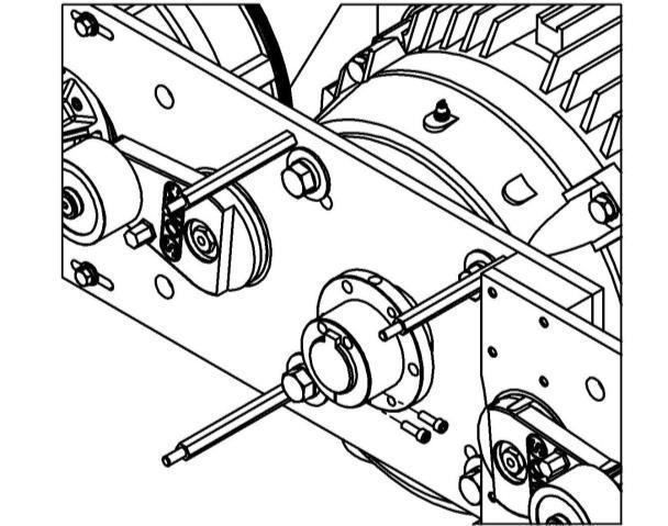
12 4.4 Blower Head Mounting Adjustment The blower head position was adjusted at the factory to the application specifications. Therefore, it should not be necessary to change the position of the blower head outlet unless the application specifications have changed or the unit is relocated. See Figure 12 for blower head rotation options. Use the following procedure to modify or adjust the blower head rotation Figure 12 - Blower Rotations Required Tools Description Qty. Description Qty. ½ inch box-end wrench 1 Rubber Mallet (optional) 1 9/16 inch box-end wrench 1 ½ inch socket 1 3/8 inch ratchet driver Blower Head Adjustment Procedure 1. Remove the belt guard using the ½ inch box-end wrench. (See Figure 13) 2. Using the 9/16 inch box-end wrench, rotate the belt tensioner counter clockwise (CCW) and remove the belt. (See Figure 14) 3. Disconnect the water-cooling lines at the quick disconnect on the blower head. (See Figure 15) (If Applicable) 4. Using the ½ inch socket, remove the eight screws from the bracket that secure the blower head. (See Figure 16) 5. Remove the water-cooling plugs from the blower head and rotate as necessary. (See Figure 17)(If Applicable) 6. Rotate the blower head to desired rotation and reinstall the eight screws to the proper torque specifications. (See Section Torque Specifications) (See Figure 18) 7. Reinstall the water-cooling lines. (See Figure 19) (If Applicable) 8. Using the 9/16 inch box-end wrench, rotate the belt tensioner counter clockwise (CCW). At the same time wrap the belt around the blower pulley, then along the right side of the idler pulley, and finally around the motor pulley. (See Figure 20) Page 8

 11.")


13 9. Slowly rotate the motor pulley to make sure the belt is seated in the grooves. 10. Verify that the belt gap is approximately ¾ inch ±1/16 inch. (See Figure 21) 11. If a ¾ inch belt gap was not achieved, use a ½ inch socket to loosen the blower head screws and slide the head. (See Figure 22) 12. Using the ½ inch box-end wrench, reinstall the belt guard. Figure 13 - Remove Belt Guard Figure 16 Remove Blower Head Figure 14 Remove Belt Figure 17 Move Water-Cooling Plugs Figure 15 Disconnect Water-Cooling Lines Figure 18 - Reinstall Blower Heads Page 9

14 Figure 19 Reconnect Water-Cooling Lines Figure 20 Reinstall Belt Figure 21 Verify Belt Gap Figure 22 - Adjust Belt Gap 5 Electrical Wiring, and Start-Up 5.1 Motor Wiring Only qualified personnel should perform motor wiring. Review motor nameplate for wiring diagram and wiring information. Many Sonic motors are dual rated for 50 and 60 hertz operation and therefore will have two nameplates. Every motor is supplied with a sticker indicating the hertz set up of the blower unit. 50 HZ 60 HZ + Page 10
 when viewing the pulley or counter clockwise (CCW) when viewing the cooling fan end of the motor.")
15 Never run a Sonic blower open to the atmosphere as this can cause overloading and damage to the motor. All Sonic blowers must rotate clockwise (CW) when viewing the pulley or counter clockwise (CCW) when viewing the cooling fan end of the motor. See the arrow mounted on the motor housing for direction of rotation. Sonic blowers are shipped with the drive belt removed. This is because the motor rotation should be checked before installing the belt. Running the blower / motor assembly backwards will cause the blower to under perform by 20%. Running backwards for prolonged periods will cause premature failure of the belts and permanent damage to the belt tensioner assembly. Refer to the Motor Rotation Sticker located on the mounting bracket for correct motor rotation and belt installation. (See Figure 23) Figure 23 - Motor Rotation Sticker Soft Start VFD or Sonic Air Diverter (Y-Verter Valve) is Required. Page 11

16 6 Blower Specifications 6.1 Blower Specification Sheet Page 12
17 6.2 Assembly Drawing Page 13
18 6.3 Parts List Sonic 200 Blower Unit Item No. Part No. Description Qty. 1 Section 0 Motor, Electric Blower Head, Sonic A-XX Pulley, Blower Tube SS Sleeve & Clamp Bracket, Sonic 200/ Bracket, Sonic 200/300 Joining Bracket, Sonic 200/ a Bracket, Sonic 200/ (IEC 160 B14 Face ONLY) Belt Guard Belt Nut, 5/16-18 Hex SS w/ Nylock Screw-3/8"-16 X 1 3/4" SHC 1 1/4" Threaded Length ZN PL Lock Washer, 3/8 High Collar SS A Pulley, Motor Belt Tensioner Assembly Screw- 5/16"-18 x 1 1/4" SHC Fully Threaded SS Lock Washer, 5/16 SS Washer, 5/16 SS Standoff Assembly Screw- 5/8"-11 x 1 1/2" HHC Fully Threaded ZN PL (40Hp & 50HP Only) Lock Washer, 5/8 ZN PL (40Hp & 50HP Only) Washer, 5/8 ZN PL (40Hp & 50HP Only) Screw- 5/16"-18 x 1" SHC Fully Threaded SS Screw-1/2"-13 x 2" HHC 2" LG, Partially Threaded ZN PL 4 (40Hp & 50HP Only) 24a Screw- M12 x 40mm HHC Fully Thrd. ZN PL(IEC 160 B14 Face ONLY) Lock Washer, 1/2 ZN PL 8 25a Lock Washer, M12 ZN PL (IEC 160 B14 Face ONLY) Washer, 1/2 ZN PL 8 26a Washer, M12 ZN PL (IEC 160 B14 Face ONLY) Screw-5/16"-18 x 1 3/4" SHC 1 1/8" Threaded Length SS Bushing Kit (25Hp & 30HP Only) 1 28a Bushing Kit (IEC 160 B14 Face ONLY) 1 28b Bushing Kit (40Hp & 50HP Only) Vibration Isolators 4 29a Vibration Isolators (IEC 160 B14 Face ONLY) 4 30 Feed-Thru Assembly, Water-Cooled Spacer (IEC 160 B14 Face ONLY) 1 Page 14
19 6.3.2 Sonic 200C Blower Unit Item No. Part No. Description Qty. 1 Section 0 Motor, Electric Blower Head, Sonic 100C A-XX Pulley, Blower Tube SS Sleeve & Clamp Bracket, Sonic 200/ Bracket, Sonic 200/300 Joining Bracket, Sonic 200/ a Bracket, Sonic 200/ (IEC 160 B14 Face ONLY) Belt Guard Belt Nut, 5/16-18 Hex SS w/ Nylock Screw-3/8"-16 X 1 3/4" SHC 1 1/4" Threaded Length ZN PL Lock Washer, 3/8 High Collar SS A Pulley, Motor Belt Tensioner Assembly Screw- 5/16"-18 x 1 1/4" SHC Fully Threaded SS Lock Washer, 5/16 SS Washer, 5/16 SS Standoff Assembly Screw- 5/8"-11 x 1 1/2" HHC Fully Threaded ZN PL 4 (40Hp & 50HP Only) Lock Washer, 5/8 ZN PL (40Hp & 50HP Only) Washer, 5/8 ZN PL (40Hp & 50HP Only) Screw- 5/16"-18 x 1" SHC Fully Threaded SS Screw-1/2"-13 x 2" HHC 2" LG, Partially Threaded ZN PL 4 (40Hp & 50HP Only) 24-a Screw- M12 x 40mm HHC Fully Threaded ZN PL (IEC 160 B14 Face ONLY) Lock Washer, 1/2 ZN PL 8 25-a Lock Washer, M12 ZN PL (IEC 160 B14 Face ONLY) Washer, 1/2 ZN PL 8 26-a Washer, M12 ZN PL (IEC 160 B14 Face ONLY) Screw-5/16"-18 x 1 3/4" SHC 1 1/8" Threaded Length SS Bushing Kit (25Hp & 30HP Only) 1 28-a Bushing Kit (IEC 160 B14 Face ONLY) 1 28-b Bushing Kit (40Hp & 50HP Only) Vibration Isolators 4 29-a Vibration Isolators (IEC 160 B14 Face ONLY) 4 30 Feed-Thru Assembly, Water-Cooled Spacer (IEC 160 B14 Face ONLY) 1 4 Page 15
20 6.4 Motor Reference Nema Motor Specifications HP 25 hp (18 kw) 30 hp (22 kw) 40 hp (30 kw) 50 hp (37 kw) Baldor Motor Specifications Part Weight Hertz No. (Standard) lbs (146 kg) lbs (165kg) lbs (233 kg) lbs (268 kg) Voltage (Standard) Full Load Amps RPM / / / / / / / / IEC Motor Specifications HP Part No. Weight 25 hp (18 kw) lbs (140 kg) Hertz (Standard) Voltage (Standard) Full Load Amps RPM / / All standard Sonic supplied motors are equipped with C-face, foot mounted, and are for 3 phase power only. Special motors are available from Sonic Air Systems and are not included in the above table. 7 Periodic Maintance 7.1 Maintenance Schedule Sonic 200 series blowers are designed for 24 hour / 365 day operation with periodic service and / or replacement of the belts and filters. The following inspection and service intervals are listed as hours of operation or elapsed time from blower installation, whichever comes first. It is always preferable to perform maintenance earlier than recommended, especially in hot, cold, wet, dirty, or otherwise hostile environments. Inspection or Task Inspect belt for wear Replace belt Inspect belt tensioner Frequency 3 Months / 1,000 Hours 12 Months / 4,000 Hours 3 Months / 1,000 Hours Page 16
21 Replace belt tensioner Inspect filter / Replace or Clean filter element Inspect motor and grease bearings Replace motor Bearing cartridge bearings Replace bearing cartridge Inspect blower and motor pulley Inspect hardware torque 7.2 Torque Specifications 3 Years / 12,000 Hours Monthly 12 Months / 4,000 Hours 5 Years / 20,000 Hours Sealed No Service Required 4 Years / 16,000 Hours 3 Months / 1,000 Hours 12 Months / 4,000 Hours Bolt Description Recommended Torque Value 1/4-20 SHCS 12 ft-lbs (16 N-m) 5/16-18 HHS or SHCS 25 ft-lbs (34 N-m) 5/16-24 HHS or SHCS 20 ft-lbs (27 N-m) 3/8-16 HHS or SHCS 30 ft-lbs (41 N-m) 1/2-13 HHS 45 ft-lbs (61 N-m) 5/8-11 HHS 60 ft-lbs (81 N-m) 7.3 Belt Replacement Procedure Tools Required Description Qty. Description Qty. 9/16 inch box end wrench 1 ½ inch box-end wrench 1 Rubber mallet (optional) Belt Replacement Procedure 1. Remove the belt guard using the ½ inch box-end wrench. (See Figure 23) 2. Using the 9/16 inch box-end wrench, rotate the belt tensioner arm counter clockwise (CCW) and remove the belt. 3. Clean any belt debris or dust from blower and pulleys. Do not use any abrasive materials on the pulley grooves as this will damage the grooves and cause subsequent belt failures. 4. Using the 9/16 inch box-end wrench, rotate the belt tensioner counter clockwise (CCW). At the same time wrap the belt around the blower pulley, then along the right side of the idler pulley, and finally around the motor pulley. (See Figure 24) 5. Slowly rotate the motor pulley to make sure the belt is seated in the grooves. 6. Verify that the belt gap is approximately ¾ inch ±1/16 inch (Factory Set). (See Figure 25) 7. If a ¾ inch belt gap was not achieved, use a ½ inch box-end wrench to loosen the blower head screws and slide the head. (See Figure 26)(See Section Torque Specifications) 8. Using the ½ box-end wrench, reinstall the belt guard. Page 17

22 Figure 23 - Remove Belt Guard Figure 24 - Install New Belt Figure 25 - Set Belt Gap to ¾ inch Figure 26 - Adjust Gap Page 18
 2. Using the 9/16 inch box-end wrench, rotate the belt tensioner arm counter clockwise (CCW) and remove the belt.")
23 7.4 Belt Tensioner Service Tools Required Description Qty. Description Qty. 1/2 inch box-end wrench 1 3/16 inch allen wrench 1 9/16 inch box end wrench 1 Rubber mallet (optional) Belt Tensioner Service Procedure 1. Remove the belt guard using the 1/2 inch box-end wrench. (See Figure 27) 2. Using the 9/16 inch box-end wrench, rotate the belt tensioner arm counter clockwise (CCW) and remove the belt. (See Figure 28) 3. Using the 3/16 inch allen wrench, secure the flat head screw from the back of the bracket while loosening the nylon-insert locknut with a ½ inch socket. This will allow the removal of the belt tensioner. 4. Caution: After removing belt tensioner, the compression springs will be exposed. Remove these springs temporarily if the new belt tensioner is not installed immediately. Wear safety glasses to prevent potential eye injury. 5. At reassembly, the static position should be approximately 25 degrees to the right of blower pulley. Install a new nylon-insert locknut to 20 ft-lbs when installing the new belt tensioner. 6. Using the 9/16 inch box-end wrench, rotate the belt tensioner arm counter clockwise (CCW). At the same time wrap the belt around the blower pulley, then along the right side of the idler pulley, and finally around the motor pulley. 7. Slowly rotate the motor pulley to make sure the belt is seated in the grooves. 8. Verify that the belt gap is approximately ¾ inch ±1/16 inch (Factory Set). (See Figure 29) 9. If a ¾ inch belt gap was not achieved, use a ½ inch box-end wrench to loosen the blower head screws and slide the head. (See Figure 30) 10. Using the 1/2 inch box-end wrench, reinstall the belt guard. Figure 27 - Remove Belt Guard Figure 28 Remove Belt Page 19
24 Figure 29 Verify Belt Gap Figure 30 Adjust Belt Gap 7.5 Bearing Cartridge Replacement Procedure Assembly Drawing Page 20
25 7.5.2 Bearing Cartridge Assembly Parts List Item Part Description Qty. No. No. 1 Housing-Blower Head Housing-Sonic 100 BC Housing-Sonic 100C BC Spindle-Sonic 100/150 Series Bearing Cartridge Spindle-Sonic 100/150C Series Bearing Cartridge Impeller-Sonic 70/100 Series Cover-Sonic %%% Pulley-Blower 16G Retainer-Impeller 1 7 & Screw-5/16-24 x 1.0 lg., SHCS SS Screw-5/16-18 x 1.0 lg., SHCS Screw-1/4-20 x 1/2 lg., SHCS SS Retainer Blower Pulley Required Tools Description Qty. Description Qty. 3/16 inch allen wrench 1 Flat Head Screwdriver (optional) 1 9/16 inch box end wrench 1 1 1/8 open end wrench 1 1/2 inch socket 1 1/4 inch allen wrench 1 3/8 inch ratchet driver 1 5/16 inch nut driver 1 1/2 inch open end wrench 1 1/2 inch deep socket Bearing Cartridge Replacement Procedure 1. Remove the belt guard using the 1/2 inch socket. (See Figure 31) 2. Using the 9/16 inch box-end wrench, rotate the belt tensioner arm counter clockwise (CCW) and remove the belt. (See Figure 33) 3. Disconnect the water-cooling lines at the quick disconnect on the blower head. (If Applicable)(See Figure 35) 4. Remove the filter or inlet screen using a flat head screwdriver or a 5/16 inch nut driver. (See Figure 32) 5. Remove cover using a 1/4 allen wrench for a Sonic 100/150 or 100/150C Series Blower. (See Figure 34) 6. Remove impeller using a 11/8 inch open end wrench and a 1/4 inch allen wrench. (See Figure 36) 7. Remove blower pulley using a 1 1/8 inch open end wrench and a 3/16 inch allen wrench. (See Figure 37 - Remove Blower Pulley) 8. Remove thermocouple using a 1/2 inch open end wrench. (See Figure 39) 9. Remove compression fitting using a 1/2 inch deep socket. (See Figure Remove bearing cartridge using a 3/16 inch allen wrench. (See Figure 38 - Remove Bearing Cartridge Hardware, Figure 40 - Remove Bearing Cartridge, and Figure 42 - Blower w/ Bearing Cartridge Removed) Page 21


26 11. Install new bearing cartridge by reversing previous steps. Figure 31 - Remove Belt Guard Figure 32 Remove Filter or Inlet Screen Figure 33 - Remove Belt Figure 34 Remove Cover Figure 35 Remove Water Cooling Tubing Figure 36 Remove Impeller Page 22


27 Figure 37 - Remove Blower Pulley Figure 38 - Remove Bearing Cartridge Hardware Figure 39 - Remove Thermocouple Figure 40 - Remove Bearing Cartridge Figure 41 - Remove Compression Fitting Figure 42 - Blower w/ Bearing Cartridge Removed Page 23
28 7.8 Recommended Spares Although the Sonic 200 blowers are designed for many years of continued operation, a number of components are wear or consumable items and must be replaced periodically. The following is a list of recommended spare components that should be used to minimize equipment or line down time: Part No. Description Recommended Qty Spindle Sonic 100/150 Series Spindle Sonic 100/150C Series %%% Pulley, Blower (16 Groove) 1 (%%% Pulley Diameter, 1.55 to 2.20) Pulley, Motor (16 Groove) Belt, 52 Lg., 16 Groove Belt Tensioner Replacement Kit Filter Element, Paper (Optional) Filter Element, Polyester (Optional) 2 See Section 7 Motor 1 8 Retro Kit Installation ( Assemble Sonic Drive to existing motor) 8.1 Tools Required Description Qty. Description Qty. 3/8 inch ratchet driver 1 1/2 inch socket 1 ¾ inch deep socket 1 ¼ inch flat head screwdriver 1 9/16 inch open-end wrench 1 Rubber mallet 1 5/16 inch allen socket 1 24 inch Straight edge 1 Caliper 1 7/32 inch allen wrench Loctite 1 #3 Drive Extension Retro Kit Installation 1. Using a 3/4 inch open-end wrench, mount the vibration isolators and uni-mounts to the motor. (See Figure 43) 2. Mount the bracket assembly to the motor and then tighten screws using the ¾ inch socket (See Figure 44) 3. Using a flat head screwdriver and a rubber mallet, wedge the screwdriver into the front face of the bushing (Do not wedge in flange area) and then slide it onto the motor shaft. (See Figure 45) 4. Set the bushing to ±.005 (33.7 mm) from the bushing flange to the bracket reference surface and remove the screwdriver. Using the 5/16 inch allen socket and 242 Loctite, install the two bushing screws. Tighten the screws to the Page 24

(See Section 7.1 - Torque Specifications) 7.")
29 specified torque, over tightening may damage the bushing. (See Figure 46, Figure 47, Figure 48, and Figure 49)(See Section Torque Specifications) 5. Tighten the bushing set screw using 242 Loctite and the 7/32 inch allen wrench. 6. Before installing the motor pulley, double check the bushing setting and then install the pulley and the three pulley screws and lock washers using the 5/16 inch allen socket. Tighten the three pulley screws to the required torque specifications. (See Figure 50)(See Section Torque Specifications) 7. Using a straight edge, check the pulley alignment from the face of the motor pulley to the face on the blower pulley. Verify that there is no gap and the alignment must be within ±1/32 inch. (See Figure 53) 8. Using the 9/16 inch box-end wrench, rotate the belt tensioner arm counter clockwise (CCW). At the same time wrap the belt around the blower pulley, then along the right side of the idler pulley, and finally around the motor pulley. Repeat process for the second belt. (See Figure 51) 9. Slowly rotate the motor pulley to make sure the belts is seated in the grooves. 10. Using the rubber mallet, adjust the belt gap to ¾ inch ±1/16 inch. (See Figure 52) 11. Using the 1/2 inch deep socket, tighten the bracket hardware. (See Section Torque Specifications) 12. Install the belt guard, secure with (4) locknuts. 13. Refer to Section 5.1 for Startup. Figure 43 - Installed Uni-mount Figure 44 - Mount Bracket to Motor Page 25


30 Figure 45-Prepare Bushing Figure 46-Installed Bushing Figure 47-Install Bushing Hardware Figure 48-Bushing Installation Page 26


31 Figure 49-Installed Set Screw Figure 50-Installed Motor Pulley Figure 51-Installed Belt Figure 52-Set Belt Gap to ¾ Figure 53-Check Alignment Figure 54-Install Belt Guard Page 27
32 Page 28
33 9 Troubleshooting Trouble Cause Remedy Section Low Flow / Pressure / Vacuum Frequent Drive Belt Failure Blower rotating backwards (Incorrect wiring) Reverse motor wiring 5 Dirty or contaminated filter Clean or replace filter element 7.1 Air leaks in the system Fix leaks 4 Drive belt slipping (Contaminated or damaged) Replace belt 4.3, 7.3 Replace pulleys 7.1 Clean pulleys 7.1 Worn pulley Replace worn pulleys 7.1 Wrong pulley size Contact Sonic Cover Wrong drive belt (Not Sonic approved) Use only Sonic supplied belts 4.3, 7.3 Incorrect piping design (Too small) Increase piping diameter 4 Cover Contact Sonic for design assistance Improper blower size for application Contact Sonic for design assistance Cover Blower rotating backwards (Incorrect wiring) Reverse motor wiring 5 Motor pulley wobbling Replace motor 5, 7.1 Replace motor bushing 7.1 Replace motor pulley 7.1 Frequent start / stops without soft start controller Install soft start motor controller 5 Install diverter valve and run continuously 5 Motor pulley out of alignment Realign motor pulley 7.1 Replace mounting bracket if damaged 7.1 Pulley grooves worn Replace pulley 7.1 Hostile environment (belts contaminated) Locate blower in safe location 4.2 Purchase Sonic blower enclosure 4.2 Wrong belts (Not Sonic approved) Use only Sonic supplied belts 4.3, 7.3 Incorrect belt installation method Properly install belts 4.3, 7.3 Worn belt tensioner Replace belt tensioner 7.1 Liquid entering blower inlet (impeller stall) Locate blower in safe location 4 Install inline filters 4 Electrical Exceeding rated CFM Contact Sonic Cover Overloading Blower RPM too high (Blower pulley too small) Contact Sonic Cover Motor has winding or bearing damage Replace motor 5 Electrical supply problems Replace drive controller 5 Thermocouple High inlet temperature Purchase water cooled blower Alarm (Optional) Reduce inlet temperature Dirty air filter Clean or replace filter element 7.1 High ambient temperature Purchase water cooled blower Water cooling low flow Increase flow rate Decrease water temperature Blower speed too high Contact Sonic Cover Broken belt (low temp) Replace belt 4.3, 7.3 Irregular / Excessive Blockage in air line Inspect plumbing and remove blockage 4 Noise Leak in air line Repair leak 4 Inlet silencer damaged Replace filter / silencer 7.1 Worn drive belt Replace belt 4.3, 7.3 Bolts loose on blower / motor assembly Tighten bolts to proper torque specifications 7.2 Motor mounts loose Tighten bolts to proper torque specifications 7.2 Blower RPM too high Contact Sonic Cover Blower is receiving vibration from nearby Install vibration isolators equipment Relocate blower assembly 4.2 Belt Jumping Off ¾ inch gap not set Adjust belt gap to ¾ 4.3, 7.3 Pulleys misaligned Realign motor pulley 7.1 Replace mounting bracket if damaged 7.1 Blower pulley wobbling Replace motor 5 Replace motor bushing 7.1 Replace motor pulley 7.1 High motor torque Replace motor with low torque equivalent 5 Blower rotating backwards (Incorrect wiring) Reverse motor wiring 5 Belt not set in grooves properly Install belt correctly 4.3, 7.3 Wrong belt (Not Sonic approved) Install Sonic supplied belt 4.3, 7.3 Page 29

34 10 Performance Guarantee Sonic Air Systems, Inc. (SAS) guarantees that each SAS supplied system will meet or exceed the designed level of performance. In the event the system does not achieve the designed performance, SAS will provide additional resources and equipment at no cost or refund 100% of the original purchase price. SAS must have quoted the system and supplied the system as quoted Buyer pays the original invoice within terms Buyer submits notification of system deficiency within 45 days of the original invoice date and allows SAS to remedy the deficiency Buyer must obtain written return authorization from SAS for any returns Buyer will return the system complete and in like new condition Page 30
35 11 Warranty Policy Sonic Air Systems, Inc. (SAS) and its employees are proud of our products and are committed to providing our customers with quality, engineered products. Scope of Warranty: All SAS designed products are warranted against defects in SAS design, workmanship and materials. Warranty Period: Blower motor units are warranted for 18 months commencing on the invoice date from SAS Retro-kits and blower heads are warranted for 12 months commencing on the invoice date from SAS Repaired blower heads are warranted for 6 months commencing on the invoice date from SAS Accessories are warranted for 24 months commencing on the invoice date from SAS Repairs Within the Scope of the Warranty: If a SAS designed product is defective and the defect occurs during the warranty period, SAS will either repair or replace, whichever SAS believes to be appropriate under the circumstances. SAS is not responsible for removal or reinstallation of product or any incidental or consequential damages resulting from the defect, removal, reinstallation, shipment, or otherwise. Repairs Outside the Scope of the Warranty: Problems with SAS products can be due to faulty installation, misapplication, inadequate maintenance, non-sas additions or modifications, or other problems not due to defects in SAS design, workmanship or materials. If SAS determines the warranty consideration is not due to defects in SAS design, workmanship or materials, the buyer will be responsible for the cost of any necessary repairs. Procedure to Receive Warranty Service: Buyer obtains a written return authorization number from SAS The authorization number must be noted on the outside of the shipping container Buyer will ship F.O.B. destination freight prepaid to SAS factory Non-compliance to any of the above procedures, damage resulting from improper packaging, or product exposed to a hazardous substance may result in SAS refusing shipment International buyer, please contact SAS for the nearest authorized warranty center Warranty exclusions: Motors shall be warranted under the respective manufacturer s policy Product with a tampered warranty seal Damage from fire, flood, theft, or vandalism Applications not approved by SAS which includes but not limited to product exposed to toxic, flammable, corrosive or other hazardous substance Damage resulting from installation or operational error Damage resulting from transportation carrier Belts, filter elements, or other similar service items Blower heads not repaired by factory authorized personnel No Other Warranties and Liability Limitation: THIS WARRANTY IS EXCLUSIVE AND IS IN LIEU OF ALL OTHER WARRANTIES WHETHER WRITTEN, ORAL OR IMPLIED. SAS LIABILITY IN ALL CASES WILL BE LIMITED TO THE REPLACEMENT PRICE OF ITS PRODUCT. AT NO TIME SHALL SAS BE LIABLE FOR ANY COSTS TO THE BUYER FOR LABOR, TRANSPORTATION OR DOWNTIME RESULTING FROM EQUIPMENT FAILURES BY SAS OR OUR SUPPLIERS. Page 31
36 12 24/7/365 Service Program Sonic Air Systems, Inc. (SAS) provides emergency product and shipping service, 24 hours a day, 7 days a week, 365 days a year, to all customers, worldwide. Shipments are made by Federal Express, UPS or UPS' Sonic Air Service or product may be picked up will-call at the SAS facility in Brea, CA USA. Simply call us at (714) during normal business hours or 7:30am to 4:30pm (Pacific Standard Time) for your immediate service needs. After hours number is (714) SAS charges Sonic list price to the buyer Distributor discounts and commissions are ineligible on this program All costs will be charged to the buyer s credit card (Master Card, Visa, or American Express, only) or to their previously established SAS credit line that is currently in good standing Payments made in US dollars only The cost for UPS SonicAir Service is approximately $ for a 25 pound package for next flight delivery within the USA International shipments will take additional time due to import regulations within the country of destination UPS SonicAir Service will attempt to have the product(s) clear international customs and import procedures, however, UPS cannot guarantee governmental acceptance SAS return authorization procedures and policies apply Page 32
37 13 Sonic Repair Policy Sonic blower heads are high-speed close tolerance machined components. The Sonic 100 blower head is rated for a 20,000 RPM maximum impeller speed. Sonic uses only the best internal components for the blower head assembly and is confident that the head will perform exceptionally in the application it was designed to perform. As with all moving components, the blower head is subject to wear and eventually will fail. Periodic maintenance and inspections will ensure the longest possible life expectancy for the blower head. The most typical mode of failure will be from the shaft bearings and with periodic inspections; this failure can be predicted to some extent. Sonic can also provide a thermocouple option to monitor the temperature of the bearing housing which is used to predict an imminent bearing failure. Due to the complexity of the internal assembly, the precision components, and the experience of Sonic assembly and repair technicians; it is not recommended that the unit be serviced or repaired in the field. Any attempt to repair the unit within the warranty period will void the warranty. Sonic does offer a repair program in the event the blower fails outside of the warranty period and the blower head is not severely worn or damaged. Sonic recommends that in the event that a blower failure will cause interrupted production, a replacement blower head be purchased as a spare item. Follow the below return authorization procedure when requesting a blower head repair: Sonic Air Systems, Inc. (SAS) recognizes the need to return product in certain circumstances. SAS requests written return authorization to track incoming shipments and to efficiently process any repairs or credit invoices. Repair Return Authorization Procedure Buyer issues a purchase order requesting and authorizing a blower head repair (reference purchase order requirements) A repair order number will be communicated by 4:30pm PST The blower head must include the blower pulley The repair order number must be noted on the outside of the shipping container Buyer will ship F.O.B. destination freight prepaid to SAS factory Non-compliance to any of the above procedures, damage resulting from improper packaging, or product exposed to a hazardous substance may result in SAS refusing shipment Repairs will be shipped within 24 hours of receipt in the USA and within 48 hours of receipt internationally Page 33
Operation and Maintenance Manual Sonic 150 / 150C
 L10028_RevK Operation and Maintenance Manual Sonic 150 / 150C Sonic Air Systems 1050 Beacon Street Brea, California 92821 Tel: 714-255-0124 Fax: 714-255-8366 www.sonicairsystems.com Page i L10028_RevK
Operation and Maintenance Manual. Sonic 85 / 85C
 L10026 Operation and Maintenance Manual Sonic 85 / 85C Sonic Air Systems 1050 Beacon Street Brea, California 92821 Tel: 714-255-0124 Fax: 714-255-8366 www.sonicairsystems.com Copyright 2006 Sonic Air Systems,
READ AND SAVE THESE INSTRUCTIONS. Centrifugal Downblast Exhaust Fan Belt Driven for Roof & Wall Mounting
 READ AND SAVE THESE INSTRUCTIONS INSTALLATION, OPERATING INSTRUCTIONS & PARTS MANUAL Centrifugal Downblast Exhaust Fan Belt Driven for Roof & Wall Mounting Electrical wiring and connections should be done
Operating and Installation Instructions
 Model Number 20902 Fabricator's Power Module Kit - Aluminum Operating and Installation Instructions CAUTION! This product is to be installed only by persons knowledgeable in the repair and modification
Positive Displacement Pump
 www.conairgroup.com U S E R G U I D E UGC028-1105 Positive Displacement Pump Models PD 3. 5, 7.5, 10, 15 and 25 Corporate Office: 724.584.5500 l Instant Access 24/7 (Parts and Service): 800.458.1960 l
Adjustable Angled Incline Conveyor Owners Manual with Operating Instructions
 Adjustable Angled Incline Conveyor Owners Manual with Operating Instructions Revision 012211 Table of Contents Basic Conveyor Features 3 Getting Started 4 Setting Up the Incline Conveyor 5 Belt Removal
Electric Actuator Installation, Operation & Maintenance Manual
 ICI Indelac Controls, Inc. Electric Actuator Installation, Operation & Maintenance Manual 6810 Powerline dr.-florence, Ky. 41042 - Telephone 859-727-7890, Tool free 800-662-9424 Fax. 859-727-4070, e-mail:
READ AND SAVE THESE INSTRUCTIONS. High Velocity Restaurant-Duty Utility Set Belt Driven for Roof Mounting
 READ AND SAVE THESE INSTRUCTIONS INSTALLATION, OPERATING INSTRUCTIONS & PARTS MANUAL High Velocity Restaurant-Duty Utility Set Belt Driven for Roof Mounting Electrical wiring and connections should be
P SERIES PUMPS. 18mm Versions Nickle-Aluminum Bronze Models: P , P , P , P , P , P , P
 P200-3100 SERIES PUMPS 18mm Versions Nickle-Aluminum Bronze Models: P217-3100, P218-3100, P219-3100, P220-3100, P221-3100, P227-3100, P230-3100 Triplex Ceramic Plunger Pump Operating Instructions/ Repair
CRD610 Automatic Fitting Inserter
 CRD610 Automatic Fitting Inserter OPERATIONS MANUAL VERSION 1.2 LAST EDITED 12.12.2018 cleanroomdevices.com 1 Table of Contents Title Page. 1 Table of Contents...2 1.0 General Product & Safety Information....3
OWNER S MANUAL SELF-PRIMING PORTABLE UTILITY PUMP
 Model 54011-0 OWNER S MANUAL SELF-PRIMING PORTABLE UTILITY PUMP Questions, problems, missing parts? Before returning to the store call AQUAPRO Customer Service 8 a.m. - 5 p.m., EST, Monday-Friday 1-844-242-2475
READ THIS MANUAL CAREFULLY BEFORE USING THE PUMP
 OWNER S MANUAL Pond Pump READ THIS MANUAL CAREFULLY BEFORE USING THE PUMP Important Notice: This manual contains important information about the installation, operation and safe use of this product. This
Operation & Maintenance Manual
 Operation & Maintenance Manual Sonic AE (All Environment) Blower Enclosure Sonic Air Systems 1050 Beacon Street Brea, California 92821 Tel: 714-255-0124 Fax: 714-255-8366 www.sonicairsystems.com Page i
NATIONAL TURBINE CORPORATION INSTALLATION, OPERATION AND MAINTENANCE INSTRUCTIONS
 NATIONAL TURBINE CORPORATION INSTALLATION, OPERATION AND MAINTENANCE INSTRUCTIONS MILLENNIUM SERIES MULTISTAGE CENTRIFUGAL BLOWERS AND EXHAUSTERS NATIONAL TURBINE CORPORATION 374 NORTHERN LIGHTS DRIVE
Maximum operating temperature for standard motors = 110 C. Shut down temperature in case of a malfunction = 115 C.
 Section 3 Maintenance & Troubleshooting General Inspection Lubrication & Bearings Type of Grease WARNING: UL rated motors must only be serviced by authorized Baldor Service Centers if these motors are
STOP CITY PRESSURE BOOSTER PUMP INSTRUCTION MANUAL
 CITY PRESSURE BOOSTER PUMP INSTRUCTION MANUAL MODEL #VP05, VP10 C US NSF/ANSI 372 255405 For loose, missing or damaged parts, or if the unit does not seem to be operating properly, please call before returning
SUNC1200 / ITEM #40882 SUBMERSIBLE UTILITY PUMP OPERATIONS MANUAL
 SUNC1200 / ITEM #40882 SUBMERSIBLE UTILITY PUMP OPERATIONS MANUAL WWW.SUNRUNNERPOOL.COM Performance Model HP GPH of Water @ Total Feet Of Lift 0 ft. 5 ft. 10 ft. 15 ft. 20 ft. 25 ft. Max. Lift SUNC1200
H.S. MACHINERY RING COMPRESSORS
 OPERATION & PARTS MANUAL Thank you for purchasing an H.S Machinery Limited Regenerative Blower. This product is manufactured under strict ISO-9001-2000 quality control guidelines to ensure your satisfaction.
SERIES PC INSTRUCTION AND OPERATION MANUAL
 MEGGA SERIES PC INSTRUCTION AND OPERATION MANUAL Models PCT and PCF Close-coupled and frame-mounted single-stage horizontal end-suction pumps. WARNING: Read this manual before installing or operating this
RSV16 Retro-Fit Cartridge Acorn Controls SV16 Valve Cartridge
 ACORN ENGINEERING COMPANY P.O. BOX 2 CITY OF INDUSTRY, CA 1 UNITED STATES OF AMERICA WWW.ACORNENG.COM RSV Retro-Fit Cartridge Acorn Controls SV Valve Cartridge Patented ADA Compliant Ligature and Vandal
Air Curtain. Installation, Operating and Maintenance Instructions
 Installation, Operating and Maintenance Instructions Save this manual for future reference. Air Curtain Model Numbers: ES026, ES036, ES042, ES048, ES060, ES072 READ THIS OWNER S MANUAL CAREFULLY BEFORE
BOILER FEED SYSTEM OPERATION AND MAINTENANCE MANUAL
 BOILER FEED SYSTEM OPERATION AND MAINTENANCE MANUAL IMPORTANT These instructions are intended as a guide for the Installing Contractor and as a reference for the Operator, Owner and Serviceman. RETAIN
UNPACKING SAFETY GUIDELINES GENERAL SAFETY INFORMATION. Operating Instructions & Maintenance Manual
 Please read and save this Repair Parts Manual. Read this manual and the General Operating Instructions carefully before attempting to assemble, install, operate or maintain the product described. Protect
WELDING FUME EXHAUSTERS & ARMS
 WELDING FUME EXHAUSTERS & ARMS The Ace 75 Series is our flexible and effective line of welding fume exhausters and extraction arms for shops that elect to exhaust their weld fumes outdoors instead of through
HOW TO INSTALL YOUR BOV
 Product Name: Product Description: Product Number: Subaru Dual port Fits WRX 01 07, WRX STI 01 08, Forester XT 06 TS-0205-1015/TS-0205-1016 ------------------------------------------------------------------------------------------------------------------------
OWNER S MANUAL EVOLUTION 3500, 4500, 5500, & 8500 SERIES PUMPS
 OWNER S MANUAL EVOLUTION 3500, 4500, 5500, & 8500 SERIES PUMPS IMPORTANT SAFETY INSTRUCTIONS When installing and using this electrical equipment, basic safety precautions should always be followed, including
CRD600 Automatic Fitting Inserter
 CRD600 Automatic Fitting Inserter OPERATIONS MANUAL VERSION 2.3 LAST EDITED 12.07.2018 cleanroomdevices.com 1 Table of Contents Title Page.. 1 Table of Contents. 2 1.0 General Product & Safety Information...3
60 Series End-Mount Brake Instructions Standard Housing
 Bulletin No. BK4655 (04/18) 60 Series End-Mount Brake Instructions Standard Housing Read carefully before attempting to assemble, install, operate or maintain the product described. Protect yourself and
User s Manual D-Series Blowers and Exhausters
 User s Manual D-Series Blowers and Exhausters D05-1 ½ HP TEFC 115/230 VOLTS, 1 PH D05-3 ½ HP TEFC 208/230/460 VOLTS, 3 PH D10-1 1 HP TEFC 115/230 VOLTS, 1 PH D10-3 1 HP TEFC 208/230/460 VOLTS, 3 PH D15-1
Motion System Components Diagram. Note: #2 Mirror Cover and X-Axis Motor Cover have been removed for visibility. Maintenance.
 Professional Laser System PLS3.75, PLS4.75, PLS6.75 and PLS6.150D Keeping the laser system clean will ensure the highest quality engraving. A clean laser system is the best performing laser system. The
READ AND SAVE THESE INSTRUCTIONS. Centrifugal Upblast Exhaust Fan (Standard & High Pressure Exhaust) Belt Driven for Roof & Wall Mounting
 Belt Driven for Roof & Wall Mounting") READ AND SAVE THESE INSTRUCTIONS INSTALLATION, OPERATING INSTRUCTIONS & PARTS MANUAL Centrifugal Upblast Exhaust Fan (Standard & High Pressure Exhaust) Belt Driven for Roof & Wall Mounting Electrical wiring
READ AND SAVE THESE INSTRUCTIONS INSTALLATION, OPERATING INSTRUCTIONS & PARTS MANUAL Centrifugal Upblast Exhaust Fan (Standard & High Pressure Exhaust) Belt Driven for Roof & Wall Mounting Electrical wiring
DESIGN-AIRE SL-RSR-EC. Installation and Operations Manual
 DESIGN-AIRE SL-RSR-EC Installation and Operations Manual DESIGN-AIRE SL-RSR-EC Installation and Operations Manual Revision: 06-Feb-17 Page 2 of 15 DESIGN-AIRE SL-RSR-EC Installation and Operations Manual
CLEAN ROOM DEVICES, LLC "WHERE TUBING AND FITTINGS COME TOGETHER"
 CLEAN ROOM DEVICES, LLC "WHERE TUBING AND FITTINGS COME TOGETHER" CRD600AF Automatic Fitting Inserter With Auto Feed OPERATIONS MANUAL (Shown with optional alcohol dispenser) 1 VERSION 1.1 LAST EDITED
SUPER PUMP OUT SYSTEM
 Congratulations on your purchase of the SUPER PUMP OUT SYSTEM. This instruction/parts manual is a guide for operating and servicing your BLUELINE SUPER PUMP OUT SYSTEM. Proper operation and service are
Hazardous Location Direct-Drive Exhaust Fans. Operating Instructions & Parts Manual
 Operating Instructions & Parts Manual EN Hazardous Location Direct-Drive Exhaust Fans Models 10D996 thru 10D999, 10E001 thru 10E007, 10E009 thru 10E020, 32ZN53 and 32ZN54 474904 PLEASE READ AND SAVE THESE
OWNER/OPERATOR MANUAL. Airmotor effective dia. in. 2.5
 MODELS 282050, 282716 & 283513 AIR OPERATED CHASSIS PUMP SERIES A OWNER/OPERATOR MANUAL SPECIFICATIONS Airmotor effective dia. in. 2.5 Airinlet Material outlet 1/4 NPTF 1/4 NPTF Liquid to Air Pressure
Effective June 1, 2013 This guide supersedes all previous versions
 Effective June 1, 2013 This guide supersedes all previous versions 3842 Redman Drive 1-800-797-7974 Fort Collins, CO 80524 www.commandlight.com L-CAS THANK YOU Please allow us to express a simple thank
READ AND SAVE THESE INSTRUCTIONS
 READ AND SAVE THESE INSTRUCTIONS Part #469003 Model Vektor -H Installation Operation and Maintenance Manual for Vektor-H Laboratory Exhaust System Receiving Greenheck model Vektor-H fans are thoroughly
DESIGN-AIRE SL-RSR-EC. Installation and Operations Manual
 DESIGN-AIRE SL-RSR-EC Installation and Operations Manual DESIGN-AIRE SL-RSR-EC Installation and Operations Manual Revision: 28-Jan-16 Page 2 of 15 DESIGN-AIRE SL-RSR-EC Installation and Operations Manual
CLEAN ROOM DEVICES, LLC "WHERE TUBING AND FITTINGS COME TOGETHER"
 CLEAN ROOM DEVICES, LLC "WHERE TUBING AND FITTINGS COME TOGETHER" CRD600 Automatic Fitting Inserter OPERATIONS MANUAL VERSION 2.1 LAST EDITED 7.25.14 DOCUMENT NUMBER 001 cleanroomdevices.com 1 Table of
Installation, Operation and Maintenance Manual
 Part #455308 Model SWB - Series 100, 200 and 300 Models SFB and SFD Installation, Operation and Maintenance Manual Please read and save these instructions for future reference. Read carefully before attempting
LifeGuardLift. LifeGuard Power Lift Model #100287A OWNERS MANUAL. Rev: 2/14/11
 LifeGuardLift OWNERS MANUAL LifeGuard Power Lift Model #100287A Rev: 2/14/11 Table of Contents 1. ASSEMBLY INSTRUCTIONS A. Lift Assembly B. Setup C. Disassembly 2. CONTROL SYSTEM A. Batteries B. Battery
INSTALLATION AND SERVICE MANUAL
 INSTALLATION AND SERVICE MANUAL Please fill in for future reference: MODEL: SERIAL NUMBER: DATE PURCHASED: * Please fill out the warranty registration card in this manual or online at www.mdminc.com XXXXXXXXX
Model AM2 M40 Panel Installation, Operation, and Maintenance Manual
 Model AM2 M40 Panel Installation, Operation, and Maintenance Manual RECEIVING AND INSPECTION Upon receiving unit, check for any interior and exterior damage, and if found, report it immediately to the
REPUBLIC MANUFACTURING RB-SERIES CENTRIFUGAL BLOWER INSTALLATION & OPERATING INSTRUCTIONS RB500 RB800 RB1200HC RB2000 RB2400 RB4000 RB4002 CE
 EPUBLIC RMANUFACTURING RB-SERIES CENTRIFUGAL BLOWER INSTALLATION & OPERATING INSTRUCTIONS RB500 RB800 RB00HC RB000 RB400 RB4000 RB400 CE Certification applies only to blower retro kits (motor not included)
Installation, Operation and Maintenance Manual
 PN 47 Models XUEB - Series 00 and 200 Installation, Operation and Maintenance Manual Please read and save these instructions for future reference. Read carefully before attempting to assemble, install,
SUNC3000 / Item #40885
 SUNC3000 / Item #40885 AUTOMATIC POOL COVER PUMP OPERATIONS MANUAL WWW.SUNRUNNERPOOL.COM 1 . Performance GPH of Water @ Total Feet Of Lift MODEL HP Max. Lift 0 ft. 5 ft. 10 ft. 15 ft. 20 ft. SUNC3000 1/3
Read this entire manual before operation begins.
 Read this entire manual before operation begins. Record below the following information which is located on the serial number data plate. Serial No. Model No. Date of Installation Contents Specifications.............
Air Actuated Hydraulic Bottle Jacks
 Air Actuated Hydraulic Bottle Jacks Operating Instructions & Parts Manual Model Number Atd-7412 Atd-7420 Capacity 12 Ton 20 Ton Atd Tools Inc. 160 Enterprise Drive, Wentzville MO 63385 Printed in China
Kysor On/Off Rear Air Fan Drive
 . Proper precautions must be taken to prevent personal injury from contact with moving parts, unintended engine start, or other hazards present when working with powered equipment. Refer to the vehicle
ALITA LINEAR AIR PUMP OPERATION & MAINTENANCE MANUAL. AL- Model Number Date Code / Serial Number Date of Purchase
 ALITA LINEAR AIR PUMP OPERATION & MAINTENANCE MANUAL AL- Model Number Date Code / Serial Number Date of Purchase LIMITED WARRANTY ALITA warrants to the original retail consumer purchaser ( Customer ) that
CLEAN AIR WORKSTATION REVERSE FLOW. Installation and Operations Manual
 CLEAN AIR WORKSTATION REVERSE FLOW Installation and Operations Manual CLEAN AIR WORKSTATION REVERSE FLOW Installation and Operations Manual Revision: 16-Jan-17 Page 1 of 12 CLEAN AIR WORKSTATION REVERSE
D-Series Blowers and Exhausters
 Operation and Maintenance Manual D-Series MONOXIVENT - SOURCE CAPTURE SYSTEMS - info@ Oct. - 2015 MONOXVENT BLOWERS AND EXHAUSTERS D05-1 D05-3 D10-1 D10-3 D15-1 D15-3 D20-1 D20-3 D30-1 D30-3 ½ HP TEFC
HA/HAB Fiberglass Wall Mount Ventilators
 HA/HAB Fiberglass Wall Mount Ventilators INSTALLATION, OPERATION & MAINTENANCE MANUAL IM-3100 August 2015 Throughout this manual, there are a number of HAZARD S that must be read and adhered to in order
TPH Series. MULTISTAGE CENTRIFUGAL PUMP Instruction Manual WALRUS PUMP CO., LTD. ISO 9001 Certified NSF/ANSI 372
 TPH Series MULTISTAGE CENTRIFUGAL PUMP Instruction Manual NSF/ANSI 372 ISO 9001 Certified WALRUS PUMP CO., LTD. EC Declaration of Conformity Manufacturer: Walrus Pump Co., Ltd. Address: No.8314, Dapiantou,
Read this entire manual before operation begins.
 Read this entire manual before operation begins. Record below the following information which is located on the serial number data plate. Serial No. Model No. Date of Installation Contents Specifications.............
RolsplicerTM. Maintenance Manual And Illustrated Parts List
 RolsplicerTM Maintenance Manual And Illustrated Parts List List of Illustrations Figure Page. Rolsplicer 3 2. Roller Adjustment 4 3. Rolsplicer 6 4. Lid Hold Down Assembly 8 5. Automatic Lid Speed Adjustment
INSTALLATION, OPERATION AND MAINTENANCE MANUAL WALL EXHAUST FANS BELT & DIRECT DRIVE XB, HV, HVA, ADD, DDS, DDP
 INSTALLATION, OPERATION AND MAINTENANCE MANUAL WALL EXHAUST FANS BELT & DIRECT DRIVE XB, HV, HVA, ADD, DDS, DDP The purpose of this manual is to aid in the proper installation and operation of the fans.
Hydraulic Long Jacks
 Operating Instructions & Parts Manual Hydraulic Long Jacks Model 44915 44930 44940 44980 44981C (Air option) Capacity 1-1/2 Ton 3 Ton 4 Ton 8 Ton 8 Ton Models 44915, 44930, 44940 & 44980 Model 44981C U.S.
4" ENVIRONMENTAL E-SERIES PUMPS OWNER'S MANUAL. DANGER warns about hazards that will cause. WARNING warns about hazards that can cause
 4" ENVIRONMENTAL E-SERIES PUMPS OWNER'S MANUAL BEFORE INSTALLING PUMP, BE SURE TO READ THIS OWNER S MANUAL CAREFULLY. CAUTION Fill pump with water before starting or pump will be damaged. The motor on
Audi R8. Ride-on Car 5F62630 OWNER S MANUAL. Keep instructions for future reference
 Audi R8 Ride-on Car 5F62630 OWNER S MANUAL Keep instructions for future reference 1 Safety The owner s manual contains assembly, use and maintenance instructions. The vehicle must be assembled by an adult
APCO CRF-100A RUBBER FLAPPER SWING CHECK VALVES
 APCO CRF-100A RUBBER FLAPPER SWING CHECK VALVES Instruction D12043 June 2016 DeZURIK Instructions These instructions provide installation, operation and maintenance information for APCO CRF-100A Rubber
MODELS 108 and 138 CRAWL SPACE PUMPING SYSTEM PREINSTALLATION CHECKLIST
 NOTICE TO INSTALLER: Instructions must remain with installation. Your Peace of Mind is Our Top Priority Product information presented here reflects conditions at time of publication. Consult factory regarding
Operation and Maintenance Manual for Joyce Dayton. Integrated Actuator- Acme Screw. Maximum capacity: 2000-pounds
 Joyce Dayton Corp. Operation and Maintenance Manual for Joyce Dayton Integrated Actuator- Acme Screw Maximum capacity: 2000-pounds IATT/DIATT IATN/DIATN WARNING! The recommendations in this manual for
Maintenance and Repair
 Maintenance and Repair WARNING ALWAYS shut off the engine, remove key from ignition, make sure the engine is cool, and disconnect the spark plug and positive battery terminal from the battery before cleaning,
GENERAL PURPOSE MIXERS
 GENERAL PURPOSE MIXERS OPERATION & MAINTENANCE MANUAL PLEASE RECORD THE FOLLOWING DATA (Information is located on the product label or packing slip) Model Number: Code: Installation Date: Installation
HOW TO INSTALL YOUR BOV
 Product Name: Product Description: Product Number: BMW Kompact BOV Kit Model specific BOV Kit TS-0203-1050/TS-0203-1250 ------------------------------------------------------------------------------------------------------------------------
SPECIFICATIONS Horsepower: 1.5 HP Running Maximum PSI: 125 PSI Tank Capacity: 15 Gallons CFM: 6 40 PSI 5 90 PSI
 15 GALLON AIR COMPRESSOR Model: 7678 DO NOT RETURN TO STORE Please call 800-348-5004 for parts and service CALIFORNIA PROPOSITION 65 WARNING: You can create dust when you cut, sand, drill or grind materials
PARTS MANUAL FOR TWO STAGE AIR COMPRESSOR
 PARTS MANUAL FOR TWO STAGE AIR COMPRESSOR SPECIFICATION CHART Model No. Horsepower Voltage-Single Phase Minimum Branch Circuit Requirement *Fuse Type Air Tank Capacity Approximate Cut-in Pressure Approximate
Hydraulic Transmission Jack, Telescopic
 Operating Instructions & Parts Manual Hydraulic Transmission Jack, Telescopic Model 4000 400 (Air Operated) Capacity 000 lbs. 000 lbs. Model 4000 Model 400 U.S. Patent No. 6,02,377! This is the safety
INSTRUCTION MANUAL G-Surge Tank #40007, #40008 & #40009
 FiTech Fuel Injection INSTRUCTION MANUAL Tank #40007, #40008 & #40009 Warning: Caution must be observed when installing any product involving fuel system parts or gas tank modifications. Work in a well
Easytork Solenoid Valve IOM
 Easytork Solenoid Valve IOM General This installation document is to be read in conjunction with the Easytork Vane Actuator IOM. Description The Easytork Solenoid Valve ( ESV ) series is intended for the
Integral Horsepower AC Induction Motors ODP Enclosure TEFC Enclosure
 $25.00 Integral Horsepower AC Induction Motors ODP Enclosure TEFC Enclosure Installation & Operating Manual 9/96 Table of Contents..............................................................................
A+ Battery Backup Power Supply For use with Hydromatic model B-A1/BV-A1
 Unit Installation and Service Manual A+ Battery Backup Power Supply For use with Hydromatic model B-A1/BV-A1 NOTE! To the installer: Please make sure you provide this manual to the owner of the pumping
IMPORTANT SAFETY INSTRUCTIONS
 OWNER S MANUAL FLO-MASTER XP2 SERIES PUMPS IMPORTANT SAFETY INSTRUCTIONS When installing and using this electrical equipment, basic safety precautions should always be followed, including the following:
U00X ULTRASONIC LEVEL SWITCH. Ultrasonic Liquid Level Switches INSTALLATION AND OPERATIONS MANUAL. For Models: U002, U003 & U004
 U00X ULTRASONIC LEVEL SWITCH INSTALLATION AND OPERATIONS MANUAL Ultrasonic Liquid Level Switches For Non-Hazardous Locations For Models: U002, U003 & U004 READ THIS MANUAL PRIOR TO INSTALLATION This manual
Thermal. Dimensions Torque Rotating. Rotating Capacity lb.ft. HPS/Min. Lb-Ft
 Bulletin No. BK4755 (11/07) 1-70 Series End-Mount Brake Instructions NEMA 2 Enclosure Read carefully before attempting to assemble, install, operate or maintain the product described. Protect yourself
VADA - V60-J PRODUCT OVERVIEW CONSTRUCTION MOTOR USAGE LIMITATIONS WARRANTY
 PRODUCT OVERVIEW The VADA series of self priming jet pumps combine the functional benefits of centrifugal pumps and the practical and qualitative benefits of self-priming pumps. The Venturi system the
INSTALLATION, OPERATION AND MAINTENANCE MANUAL WALL EXHAUST FANS BELT DRIVE XBL FANS
 INSTALLATION, OPERATION AND MAINTENANCE MANUAL WALL EXHAUST FANS BELT DRIVE XBL FANS The purpose of this manual is to aid in the proper installation and operation of the fans. These instructions are intended
CLIF MOCK TM. Model 5030 Orifice Fitting. User Manual. Manual No , Rev. B
 CLIF MOCK TM Model 5030 Orifice Fitting User Manual Manual No. 25165003, Rev. B 2007 Cameron International Corporation ( Cameron ). All information contained in this publication is confidential and proprietary
UNPACKING SAFETY GUIDELINES GENERAL SAFETY INFORMATION. Operating Instructions & Maintenance Manual
 Please read and save this Repair Parts Manual. Read this manual and the General Operating Instructions carefully before attempting to assemble, install, operate or maintain the product described. Protect
NECO Pumping Systems
 INSTALLATION OPERATION & MAINTENANCE INSTRUCTIONS For Your NECO Pumping Systems PACKAGED CIRCULATING SYSTEM THIS COMPLETELY ASSEMBLED, TESTED, PACKAGED CIRCULATING SYSTEM IS OF THE HIGHEST QUALITY AND
ROUSH Performance Air Induction Kit Pt # R
 ROUSH Performance Air Induction Kit Pt # R07060087 C. A. R. B. EO # D-418-14 See Important EO Note below Included with your ROUSH Intake System Kit is a sticker with a California Air Resources Board (C.
Installation Manual. D3600- Series Duplex Grinder Systems. Contents
 Installation Manual 7353000E D3600- Series Duplex Grinder Systems Features: 36 Diameter Fiberglass Tank Available in 48, 60, 72, 84, and 96 heights LSG Single or LSGX 2 Stage 2HP Grinder Pumps Factory
Installation Operation & Maintenance Manual. Oil-Free (Dry) Rotary Vane Vacuum Pump Systems
 Rotary Vane Vacuum Pump Systems") Installation Operation & Maintenance Manual Oil-Free (Dry) Rotary Vane Vacuum Pump Systems Part No. 9983-0000-S07 / November 2018 OIL-FREE (DRY) ROTARY VANE VACUUM PUMP SYSTEMS TABLE OF CONTENTS CUSTOMER
Installation Operation & Maintenance Manual Oil-Free (Dry) Rotary Vane Vacuum Pump Systems Part No. 9983-0000-S07 / November 2018 OIL-FREE (DRY) ROTARY VANE VACUUM PUMP SYSTEMS TABLE OF CONTENTS CUSTOMER
DATA SHEET CP MOTORIZED PUMP UNITS 3CP1120, 3CP1130, 3CP1140 5CP2140WCS, 5CP2150W
 DATA SHEET CP MOTORIZED PUMP UNITS Motors: Motors: 8023ES, 8024ES, 8025ES 8026ES, 8027ES, 8028ES, 8029ES, 8040ES, 8042ES Used on Pump Models: Used on Pump Models: 3CP1120, 3CP1130, 3CP1140 5CP2140WCS,
Jet Fans. Instruction Manual READ AND SAVE THESE INSTRUCTIONS WARRANTY
 Jet Fans Instruction Manual READ AND SAVE THESE INSTRUCTIONS WARRANTY All Leader Fan products are guaranteed to be free from defects of workmanship or material and to function satisfactorily when properly
Air Operated Diaphragm Pumps Operating and Maintenance Instructions
 Product & Chemical Disclaimer The user must take responsibility in the selection of the products materials of construction. Empire Pumps Ltd will act in an advisory role and offer recommendations; however,
Series: PFUEG 1/12HP, 5000 RPM, 60 Hz Utility Pumps
 INSTALLATION MANUAL Series: 1/12HP, 5000 RPM, 60 Hz ISP No: - 6/09 General Safety Information Before installation, read the following instructions carefully. Failure to follow instruction and Safety information
Innovatech User Manual. Predator 2400 T H E S U R F A C E P R E P A R A T I O N S P E C I A L I S T S
 Innovatech User Manual Predator 2400 T H E S U R F A C E P R E P A R A T I O N S P E C I A L I S T S CONTENTS Introduction... 3 Delivery... 3 Grinder Specifications... 4 Safety Warning... 4 Controls and
COMPRESSED AIR LOADER MODEL: AL-1
 COMPRESSED AIR LOADER MODEL: AL-1 Document: AL-1 IM 10-22-2011 TABLE OF CONTENTS Important Notices and Precautions 3 Quick Installation 4 Product Description 4 Principle of Operation 5 Unpacking and Inspection
Installation & Operating Manual
 Installation & Operating Manual 25INV-M 1/17 Edition NV Series Vertical Booster Stainless Steel Multistage Centrifugal Pump Congratulations On Your Choice In Purchasing This Webtrol Pump Its Quality is
Read this entire manual before operation begins.
 Read this entire manual before operation begins. Record below the following information which is located on the serial number data plate. Serial No. Model No. Date of Installation Contents Specifications.............
PHANTOM (PH10 and PH12) COMMERCIAL AND INDUSTRIAL SERIES
 COMMERCIAL AND INDUSTRIAL SERIES") Document No: ICM-IOM Date: 0411 PHANTOM (PH10 and PH12) COMMERCIAL AND INDUSTRIAL SERIES Installation, Operation and Maintenance Manual Please read and save these instructions. Read carefully before attempting
Document No: ICM-IOM Date: 0411 PHANTOM (PH10 and PH12) COMMERCIAL AND INDUSTRIAL SERIES Installation, Operation and Maintenance Manual Please read and save these instructions. Read carefully before attempting
INSTALLATION AND OPERATING MANUAL
 Publication T3-76, Rev. 1 Dated: May 9, 21 INSTALLATION AND OPERATING MANUAL MODEL: T3-I TURBOTWIN Engine Air Starter AN96-419 From Tech Development Inc 68 Poe Ave. Dayton OH 45414 Tel: (937) 898-96 Fax:
Section 5 Reports Installation & Start Up Reports... Reports 1-3 Maintenance Report Warranty & RGA Information Contact Information
 19 2022 2324 25 26 Section 5 Reports Installation & Start Up Reports... Reports 1-3 Maintenance Report Warranty & RGA Information Contact Information 12 3 TEFC TEFC 8.0 7.0 6 5.08 4 126 80863 12
Air Operated Double Diaphragm Pump. M-Pump ½ Metallic Non Metallic Pump INSTALLATION, OPERATION & MAINTENANCE MANUAL
 Air Operated Double Diaphragm Pump M-Pump ½ Metallic Non Metallic Pump INSTALLATION, OPERATION & MAINTENANCE MANUAL 0.5 I.O.M rev 05. 12/2015 INDEX Title Section Introduction.1 Safety.2 Warranty, General
MODEL MC1500 Installation and Operation Manual Important:
 MODEL MC1500 Installation and Operation Manual Important: This manual contains specific cautionary statements relative to worker safety. Read this manual thoroughly and follow as directed. It is impossible
INSTRUCTIONS SMOKE BLOWER WITH HONDA ENGINE PART NUMBER
 1 INSTRUCTIONS SMOKE BLOWER WITH HONDA ENGINE PART NUMBER 303-568 CHERNE INDUSTRIES INCORPORATED 1-800-THE PLUG 5700 LINCOLN DRIVE (1-800-843-7584) MINNEAPOLIS, MN 55436-1695 FAX: 1-800-843-7585 www.cherneind.com
THE GIANT-VAC PTO BLOWER MODELS 2000*/3200**/4000***
 THE GIANT-VAC PTO BLOWER MODELS 2000*/3200**/4000*** Congratulations! ASSEMBLY INSTRUCTIONS AND OPERATOR S MANUAL You have just purchased one of the finest pieces of outdoor power equipment on the market