Aircraft safety & fuel 101
|
|
|
- Abraham King
- 5 years ago
- Views:
Transcription


1 Aircraft safety & fuel 101 Stuart Tucker Product Support & Technical Services Senior Manager, Aerospace Billy Walker Product Support Manager, Titchfield
2 Agenda Aircraft Safety SFAR 88 & CDCCL Special Federal Aviation Regulation No. 88 Critical Design configuration control limitations Fuel 101 A journey through the fuel system 3

3 Introduction There is currently approximately 24,600 aircraft both commercial and cargo, flying in the world today Right now there are approximately 600,000 passengers and crew in the air That equates to 4 Billion passengers each year take to the sky's When was the last time you travelled on an aircraft? What did you think about? Good Seat Will the food be good Showing good Movies 4

4 Introduction Did you think about the safety of the aircraft? 5


5 Introduction Then Who Does? Does!!!!! 6
6 Contents What is Part 21 & Part 145 requirements SFAR 88 Ignition Prevention CDCCL 7
7 EASA part *** Regulations EASA Part 21 Subpart G. Production organisations need to be able to demonstrate and maintain compliance with European Aviation Safety Agency requirements EASA Part 145 Is the Implementing Regulation issued by European Aviation Safety Agency (EASA) for the aircraft maintenance sector (Maintenance Organisation Approval) establishing the requirements to be met by an organisation to qualify for the issue or continuation of an approval for the maintenance of aircraft and components. Therefore Eaton are governed by the rules laid down by the controlling Airworthiness authority, failure to abide by the regulations can result in loosing our license to manufacture and repair aircraft components 8
8 History Since the 1960 s, there have been several key Aircraft accidents involving aircraft fuel tanks exploding, this called into question the safety of aircraft fuel systems, this fundamental safety strategy applied to fuel systems of large commercial aircraft 9

9 707 Elkton Maryland (December 8th 1963) Portion of fuselage of Pan Am Flight #214 in cornfield near Elkton MD While holding at 5,000 feet, aircraft struck by lightning Wing exploded In-flight break-up, 81 killed Airplane fuelled with mixture of Jet A and JP-4 fuels 10


10 Incidents 11

11 737 Manila (May 11, 1990) Philippine Air Lines, B ; EI-BZG While pushing back from gate, empty centre fuel tank exploded Airplane destroyed by fire 8 killed Airplane had been fuelled with Jet A fuel 12


12 747 New York (July ) While climbing through 13,000 feet, empty centre tank exploded In-flight break up of airplane 230 killed Airplane had been fuelled with Jet A 13

13 737 Bangkok (March 3 rd 2001) While parked at gate, empty centre tank exploded Airplane destroyed by fire 1 flight attendant killed Airplane had been fuelled with Jet A fuel 14
.")
14 737 China Airlines Aug 2007 Fuel that was leaking from the fuel tank on the right wing caught fire and the aircraft was engulfed in flames. There were 165 people on board China Airlines flight, and 157 passengers (including two infants). Everyone on board was evacuated from the aircraft and there were no Fatalities or injuries The aircraft was badly damaged and destroyed by fire, leaving only part of the airframe intact. 15
15 Key accidents Elkton Manila New York Bangkok Exact source of ignition was never determined High Flammability of fuel tanks was questioned Corrective actions based on most likely scenarios 16
16 Findings Efforts to resolve TWA 800 led the FAA to conclude that: 1. Many current aircraft had similar short comings in their ignition prevention approaches 2. An additional independent layer of protection is needed to Back-Up the ignition prevention strategy TWA 800 brought a realisation that some Fuel Tanks could be flammable for a large portion of their operational time U.S. NTSB Most Wanted List from the investigation was: 1. To reduce ignition source 2. Flammability Reduction 17
17 SFAR 88 ignition prevention In response to these findings, the FAA issued Special Federal Aviation Regulation No. 88 in June of 2001 Regulation No. 88 re-examined the existing commercial fleet relating to ignition prevention Goal of SFAR 88 was to preclude ignition sources 18
18 Summary Flammability exposure is a major factor in fuel tank explosion risk Balanced Approach of Ignition Prevention and Reduced Flammability can provide a substantial improvement in fuel tank safety So What does this mean to Eaton? 19
19 CDCCL Critical Design Configuration Control Limitations (CDCCL): The purpose of the CDCCL is to provide instructions to retain the critical ignition source prevention feature during configuration change that may be caused by alterations, repairs, or maintenance actions The CDCCL is identified by the type certificate holder The manual instructions must be followed to the letter of the law 20
20 Summary Eaton is responsible for the quality of our manufactured and repaired products We ALL have a key part to play in the safety of the aircraft we support Flying is still the safest form of transport and that is thanks to you all. If you identify any errors with Eaton s documentation you must STOP and raise your concerns We have very clear procedures and these must be followed at all times 21
21 Questions/Comments 22
22 23
23 Aircraft safety & fuel 101 Stuart Tucker Product Support & Technical Services Senior Manager, Aerospace Billy Walker Product Support Manager, Titchfield

24 Fuel & Inerting Systems Experience #1 electric boost-pump supplier First composite-wing integrated fuel system for B787 Range of pumps and valves on commercial platforms Industry leader for in-flight and ground refueling systems Digital gauging offers improved reliability, accuracy, weight reduction, and lifecycle cost Most Recent Platforms B787, A380, KC-390, G500/600, MA700 Fuel Distribution and Vent Systems Inerting System Fuel Quantity Indicating System Conveyance Aerial Refuelling System Technology Focus Lightweight and compatible components for composite wings Next generation inerting system for reduced bleed air consumption and improved life cycle cost Advanced fuel system management 25
25 Airframe OEM customer base Over 250,000 fuel system components supplied for over 100 different aircraft 26
26 In the beginning 27

27 Early fuel system the basics Filler Cap Fuel Tank Engine shut-off Valve Engine Feed Line Fuel management system 28
28 Early fuel system the basics Refuel And Defuel System Filler cap Fuel Quantity Indication systemm e f Gauge Vent System Air Out Fuel tank inerting system or onboard inert gas generating systema system Fuel Management system Fuel Transfer system Fuel tank(s) Fuel Pump(s) Nitrogen Valve Engine Fuel Feed line Engine Feed System Thermal Management system 29
29 Fuel system architecture and functions ENG 1 ENG 2 Refuel / defuel Engine feed Refuel Adapters Fuel/ Oil Hx Return to Tank Isolation Valve Defuel / Isolation Valve EDP Fuel Flow Engine Spar Valve Fuel Scavenge Valve Crossfeed Valve Main Tank Jettison Isolation Check Valve Fuel Scavenge Valve Fuel Flow Engine Spar Valve Fuel/ Oil Hx EDP Defuel / Isolation Valve Return to Tank Isolation Valve APU feed Fuel transfer Surge Hot Fuel Return Spar Valve Water Scavenge 1 B Left Main B Suction Feed Flame Arrestor Fuel Scavenge Center Flame Arrestor Fuel Scavenge Hot Fuel Return Spar Valve B B Water Scavenge Suction Feed Right Main Surge Vent system Sump Drain Valve APU (DC) Jettison Gravity Transfer Valve O/J PS PS O/J Jettison Gravity Transfer Valve Sump Drain Valve Water management & tank draining Refuel Valve Refuel Valve Sump Drain Valve APU Spar Valve Drain Valve (to main tank) APU Shroud in pressurized section of fuselage Sump Drain Valve Refuel Valve Jettison Isolation Valve Jettison Isolation Valve Sump Drain Valve Refuel Valve Sump Drain Valve Drain Valve (to main tank) Refuel Valve Refuel Valve 2" Jettison Nozzle Valve APU Compartment Firewall Flame Arrestor Drain Mast 2" Jettison Nozzle Valve 2/10/05 pst 30


30 Airframe fuel distribution systems Technologically 3 advanced thermally efficient fuel pump Check valve Pedestal mounted ball valve 4 Refuel valve Twin motor actuator 6 Engine feed pumps 7 Trim transfer pump 8 Pressure transducer 9 Override jettison pump 10 Jet pump 11 Engine feed tube 31
31 Ground fuelling system 32
32 Background Eaton is the Leading Supplier of Aviation Ground Fuelling Equipment World s largest manufacturer of hydro-mechanical and digital equipment for the aviation refuelling industry ClaVal 4% Others 8% Meggit 18% Eaton 70% 33


33 Ground fuelling Only Company Delivering Fuel From Airport Storage To The Main Engine 34


34 Ground fuelling Bottom Loading Systems Quick Disconnects, Dry-Breaks and Couplings Inline & Bypass Control Valves 35


35 Hydrant pit valve 36


36 Ground fuelling Hydrant Couplers 37


37 Ground refuelling operations 38
38 On-aircraft refueling 39


39 Types of aircraft access 40

40 Types of fuel connecter access 41


41 Underwing refuelling cap 42

42 Under-wing refuelling nozzle 43


43 Aircraft pressure refuelling coupling Frangible jaw ring Jaw Ring Frangible joint breaks at overload conditions Mounting to aircraft spar Excessive side loading can result in breakage Note: As a safety feature the frangible jaw ring is designed to shear when excessive force is applied 44
44 Ground refuelling operations Refuelling pressures 50 psi Flow rates about 1400 L/min (369 USGal/Min (equipment rated up to 3500 L/min ( 924 USGal /Min) Time to refuel an A320 or B737 normal load 10 to 15 mins Time to refuel a B to 50 mins 45

45 Refuel control panel 46

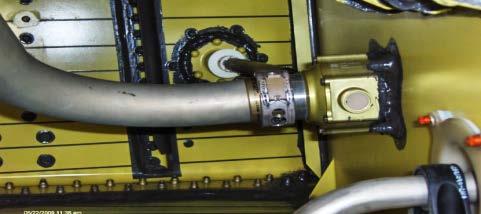
46 Pressure refuelling valves and canisters Canister Manual override Solenoid valve The refueling valve (rated at 120 PSI and 110 IPGM) is operated by a solenoid which is linked to pressure switches in the tanks which sense that the pressure is building up as the fuel levels rise In the unlikely event of a solenoid failure, there is a manual override facility which the refueling operator can use to manually refuel the Aircraft Canisters are fitted to the aircraft spar and allow the pressure refueling valve to be removed from the canister without spillage of fuel as a non-return valve automatically closes as the refueling valve is removed 47


47 Fuel flow path Piston open direction Fuel In Flow path Fuel In 48
48 Fuel tank construction/architecture Integral tanks - inside the aircraft structure sealed to allow fuel storage This type is the "wet wing" commonly used in larger aircraft and are part of the aircraft structure, they cannot be removed for service or inspection Inspection panels are be provided to allow internal inspection, repair, and overall servicing of the tank Most large transport aircraft use this system, storing fuel in the wings and/or tail of the airplane 49


49 Inside a fuel tank 50
50 Fuel tank construction/architecture Rigid removable tanks - installed in a compartment designed to accommodate the tank, typically of metal construction, and may be removed for inspection, replacement, or repair The aircraft does not rely on the tank for structural integrity These tanks are commonly found in smaller general aviation aircraft 51

51 Refuel control panel 52
52 Fuel tank construction/architecture Bladder tanks - are reinforced rubberized bags installed in a section of aircraft structure designed to accommodate the weight of the fuel The bladder is rolled up and installed into the compartment through the fuel filler neck or access panel, and is secured by means of metal buttons or snaps inside the compartment. Many high-performance light aircraft and some smaller turboprops use bladder tanks 53

53 Refuel control panel 54
54 Fuel system tank arrangement and capacities long range (typical ) Center Tank Center Tank Dry Bay Surge Tank Main Tank 55
55 Engine feed system 56


56 Fuel boost pumps and canisters Two general configurations for most medium large commercial aircraft: Base-mounted through the lower surface of the wing Rear spar-mounted Pros and cons of each design, including: Base-mounted Pump inlet low in tank and improves pump-down May be concerns over pump location and stress raisers Routing of power supply leads and protection of connectors Spar-mounted Pump above base of tank so reprime stage required, increasing power level Base-mounted pump and canister Spar-mounted Pump and canister 57

57 Pump base-mounted with remote inlet Occasionally it is necessary to incorporate a remote inlet with a base-mounted pump Unable to position pump at the lowest point of the tank for accessibility or stress concerns Results in use of reprime stage within the pump 58
58 Variable frequency power use Historically, large commercial transport aircraft have used pumps powered from a 400Hz 3-phase power supply and employing a simple, reliable 3-phase induction motor With the introduction of variable frequency power systems induction motors are not always suitable over the frequency/operating range It may be possible to use modified induction motor designs for some applications. However, for other applications it may be necessary to incorporate electronic power conversion: Variable frequency constant frequency Variable frequency DC 59


59 Feed pump with integral power conversion 12 pulse TRU Drive electronics cold wall DC link filter BLDC motor 60


60 Fuel pump with remote power conversion Pump and housing Remote inverter Conventional 3-phase ac-powered pump & housing with remote electrical power conversion (inverter) Could be Brushless DC with remote electronics, dependent on operational requirements 61
 Secondary (induced) flow usually from fuel tank For engine feed, fuel transfer or water scavenge Pump optimised to provide sufficient outlet pressure")
61 Jet pumps Applications including: Main engine feed (typically small & mid-size a/c) Tank tank fuel transfer Keep collector cell/feed tank full Fuel & water scavenge High pressure fuel flow to the nozzle (from fuel boost pump or engine return) Secondary (induced) flow usually from fuel tank For engine feed, fuel transfer or water scavenge Pump optimised to provide sufficient outlet pressure for engine feed or transfer No moving parts high reliability but low efficiency 62
62 Fuel actuated valves 63


 May require thermal relief to prevent")
63 Flow control valves May be used for a variety of purposes, including: engine shut-off, transfer control, refuel control, jettison Typically electrically-actuated ball valves for commercial aircraft, although can be other designs, including: butterfly & gate valves May be line-mounted or bulkhead-mounted (e.g. pedestal, remote shaft-driven) May require thermal relief to prevent over-pressurization of fuel lines 64


64 Thermal relief valve operation One or more thermal relief valves may be fitted to the valve Either on the valve ball or in the body Allow pressure relief of sealed areas in pipework due to thermal expansion of the fuel 65
65 Vent system 66


66 Tank fuel vent valves As the fuel enters the tanks it is essential that the air in the tanks which is displaced by the fuel is vented overboard, this is achieved by Air No Fuel or Vent valves fitted in the top of the Aircraft tanks As the tanks fill up the air is vented through the vent valves and is discharged overboard The valve has a float assembly linked to a valve seat which floats on the fuel. When the fuel level reaches the prescribed level in the top of the tank the valve seat closes, thus preventing overboard fuel leakage The valve also allows air to enter the airspace above the fuel to prevent vacuum in the tank Product range includes valves with pressure relief to prevent over-pressurization of the fuel tanks 67
67 Water scavenge and drain 68


68 Water scavenge systems Jet pumps Jet pump Fitted in the bottom of the fuel tank With a motive flow it uses the Venturi effect to draw water and fuel from the bottom of the fuel tank, emulsifying this mixture with the primary flow before entry into the system Water drain valves Water drain valves are fitted in the bottom of fuel tanks A non return valve within the unit is operated externally and excess water is collected from the wing by use of an adaptor and collector bottle Moves to a more comprehensive active water management system Water drain valve and adaptor 69

69 Fuel measurement 70


70 Fuel monitoring MFLIs used as a secondary back up system if the aircraft FCMC is inoperative Manual readings are taken from the MFLIs in each tank on the aircraft The pilot can allow the aircraft to depart with these manual readings with the complete assurance that the aircraft has enough fuel to complete the flight plus an acceptable safety margin Typical component location Level sensor Pressure switch Temperature sensor 71
71 Questions/Comments 72

72 73
Aging Systems Workshop Fuel Tank Safety- FINAL RULE
 Aging Systems Workshop Fuel Tank Safety- FINAL RULE November 8, 2001 Mike Dostert Transport Airplane Directorate Federal Aviation Administration Phone: 425-227-2132, E-Mail: mike.dostert dostert@faa.gov
National Transportation Safety Board Robert L. Swaim Aviation Engineering NRS. Fire Issues
 Robert L. Swaim Aviation Engineering NRS Fire Issues October 23, 2001 The Safety Board has investigated aircraft fires since inception on April 1, 1967 BOAC 707 uncontained engine failure results in in-flight
Staff Instruction. Ferry Fuel System Field Acceptance Criteria
 Staff Instruction Subject: Ferry Fuel System Field Acceptance Criteria Issuing Office: Civil Aviation Activity Area: Qualifying Document No.: SI 500-020 File No.: A 5500-15-1 U Issue No.: 01 RDIMS No.:
Improving Maintenance Safety Through Collaboration
 Improving Maintenance Safety Through Collaboration IATA World Maintenance Symposium 23 September 2015 Presented by Christopher A. Hart, Chairman U.S. National Transportation Safety Board 1 Outline NTSB
DGINT/2. Flammability Reduction. Fuel tank safety. Purpose of the meeting. Review of conclusions from June 2004 workshop. Flammability Reduction
 Flammability Reduction Fuel tank safety Flammability Reduction Purpose of the meeting Review of conclusions from June 2004 workshop Background Rulemaking framework for FTS Rulemaking task for FRS Ignition
FUEL TANK SAFETY / EWIS CONTINUATION TRAINING
 FUEL TANK SAFETY / EWIS CONTINUATION TRAINING Q1 & 2 2017 Page 1 of 14 CONTENTS: 1 SFAR INTRODUCTION 2 Ground Fault Interrupters & Universal Fault Interrupters 3 EWIS Introduction 4 Related Airworthiness
DC3Training.com N28AA DC-3 Pilot s Handbook
 SECTION 9 FUEL SYSTEM Index General page 2 Operation page 5 Limitations page 6 Troubleshooting page 6 5/15/2012 crew@dc3training.com 1 GENERAL A. Fuel Tanks The dual fuel system has a total capacity of
FUEL MODEL 750 BAGGAGE COMPARTMENT SMOKE DETECTION
 MODEL 750 SECTION II AIRPLANE AND SYSTEMS System test is accomplished by turning the cockpit rotary test switch to FIRE WARN. Proper system operation is indicated by illumination of the APU FIRE indicating
Aviation Ground Fueling Solutions
 Aviation Ground Fueling Solutions for Commercial and Military Applications Fueling/Refueling Nozzles & Accessories Military Underwing Refueling Nozzles For pressurized underwing or fuselage refueling of
SFAR 88/CDCCL COURSE
 SFAR 88/CDCCL COURSE Welcome to Fuel Tank Safety Training - AD Mandated Course The purpose of this course is for you to become familiar with the requirements for: Critical Design Configuration and Control
DESCRIPTION AND OPERATION FUEL SYSTEM
 2.14. The fuel system total capacity is 1597 LTS (421.9 U.S. Gallons) and the total usable fuel capacity is 1583 LTS (418.2 U.S. Gallons). Each engine is fed by its own fuel system consisting of four interconnected
European Aviation Safety Agency
 Page 1/8 European Aviation Safety Agency EASA TYPE CERTIFICATE DATA SHEET Cirrus Design SF50 Type Certificate Holder: Cirrus Design Corporation 4515 Taylor Circle Duluth, Minnesota 55811 United States
TECHNICAL MANUAL AVIATION UNIT AND AVIATION INTERMEDIATE MAINTENANCE MANUAL CH-47D HELICOPTER
 TECHNICAL MANUAL TM 55-1520-240-23-8 AVIATION UNIT AND AVIATION INTERMEDIATE MAINTENANCE MANUAL CH-47D HELICOPTER This manual together with TM 55-1520-240-23-1, TM 55-1520-240-23-2, TM 55-1520-240-23-3,
DASSAULT AVIATION Proprietary Data
 F2000EX EASY 02-28-00 CODDE 1 PAGE 1 / 2 TABLE OF CONTENTS 02-28 ATA 28 - FUEL SYSTEM 02-28-00 TABLE OF CONTENTS 02-28-05 GENERAL Introduction Sources Fuel tank location 02-28-10 DESCRIPTION Sub-systems
Moving Forward With the 787
 Moving Forward With the 787 Mike Sinnett Vice President and Chief Project Engineer March 15, 2013 Welcome Commitment to safety 787 systems Event details Comprehensive solution set Go-forward plan 2 Our
AIRCRAFT GENERAL KNOWLEDGE (1) AIRFRAME/SYSTEMS/POWERPLANT
 AIRFRAME/SYSTEMS/POWERPLANT") 1 In flight, a cantilever wing of an airplane containing fuel undergoes vertical loads which produce a bending moment: A highest at the wing root B equal to the zero -fuel weight multiplied by the span
1 In flight, a cantilever wing of an airplane containing fuel undergoes vertical loads which produce a bending moment: A highest at the wing root B equal to the zero -fuel weight multiplied by the span
Proposed Special Condition C-xx on Rudder Control Reversal Load Conditions. Applicable to Large Aeroplane category. Issue 1
 Proposed Special Condition C-xx on Rudder Control Reversal Load Conditions Introductory note: Applicable to Large Aeroplane category Issue 1 The following Special Condition has been classified as an important
1. All aircraft fueling equipment shall have a Filter/Separator or a Full-Flow Fuel Monitor.
 No. 401 STANDARD SAFETY PROCEDURES STANDARD EQUIPMENT LIST FOR FUELING VEHICLES OBJECTIVE: To ensure the safety of property and personnel, the following minimum operational/equipment list, for each fueling
Registration Number. Serial Number
 Registration Number Serial Number This supplement must be attached to the DMCR Approved Airplane Flight Manual listed on page 2 of this supplement or later approved revision and must be carried in the
727 Fuel System. Fuel is stored in both wing and a center tank. Total fuel capacity is 767 gallons or 50,800 pounds.
 727 Fuel System General Fuel is stored in both wing and a center tank. Total fuel capacity is 767 gallons or 50,800 pounds. U.S. gallons Pounds L/M. 1793 11,500 R/M. 1793 11,500 Center 4086 27,800 Maximum
Installation, Operating, Maintenance and Safety Instructions for CW332 Pressurised water system for boats 24 volt d.c.
 24V DC-CW332 DOC531/11 Installation, Operating, Maintenance and Safety Instructions for CW332 Pressurised water system for boats 24 volt d.c. To obtain the best performance from your Pressurised water
. Los Angeles International Airport Rules and Regulations SECTION 09 FUELING
 Current National Fire Protection Association (NFPA) 407, International Fire Code (IFC), and the Los Angeles Fire Code (LAFC) shall be adhered to in addition to these regarding fueling. 9.1 Aircraft Fueling
Brochure, Flight control and actuation systems EN ver. 1, June 2016
 www.saab.com Brochure, Flight control and actuation systems EN ver. 1, June 2016 FLIGHT CONTROL AND ACTUATION SYSTEMS SAFETY ASSURED FLIGHT CONTROL AND ACTUATION SYSTEMS > RELIABLE PRODUCTS RELIABLE PRODUCTS
LANCAIR LEGACY PRE-TEST FLIGHT INSPECTION (8-04)
") LANCAIR LEGACY PRE-TEST FLIGHT INSPECTION (8-04) OWNER PHONE # ADDRESS N SERIAL # AIRCRAFT TYPE DATE / / TACH TIME hrs. TOTAL TIME hrs. EMPTY WEIGHT CG. PAINT & INTERIOR? YES NO ENGINE TYPE PROPELLER ALL
LANCAIR LEGACY PRE-TEST FLIGHT INSPECTION (8-04) OWNER PHONE # ADDRESS N SERIAL # AIRCRAFT TYPE DATE / / TACH TIME hrs. TOTAL TIME hrs. EMPTY WEIGHT CG. PAINT & INTERIOR? YES NO ENGINE TYPE PROPELLER ALL
FUELING SYSTEM. With the fueling hose connected to the fueling manifold and the three fueling valves open, fuel is supplied to the three tanks.
 FUELING SYSTEM System The fueling station provides means to fill and service the fuel tanks to any specified level. In addition, the fuel tanks can be defueled or fuel can be transferred from tank to tank
EMBRAER 120 Fuel System
 EMBRAER 120 Fuel System GENERAL DESCRIPTION The fuel system supplies fuel at flow and pressure rates as required for the engine and APU operation. The fuel is contained in wing tanks. Each wing has two
PRESS RELEASE Q & A. The company decided from the onset to operate under a Boeing licensing umbrella to design and produce parts to Boeing standards.
 Super98 PRESS RELEASE Q & A How was Super98 started and why? Super98 was started in 2007 by private entrepreneurs and investors with the vision to extend the economic life of the popular MDC heritage TwinJets.
FUEL TANK SAFETY / EWIS CONTINUATION TRAINING
 FUEL TANK SAFETY / EWIS CONTINUATION TRAINING Q3 & Q4 2016 Page 1 of 13 CONTENTS: 1 INTRODUCTION 2 Fuel Tank Safety 3 EWIS 4 Related Airworthiness Directives 5 Fire risk leads RAF to withdraw Sentry from
CHAPTER 11. Page TABLE OF CONTENTS /02 DESCRIPTION. General Description Controls and Indicators
 CHAPTER 11 FUEL SYSTEM Page TABLE OF CONTENTS 11-00-01/02 DESCRIPTION General 11-10-01 Description 11-10-01 Controls and Indicators 11-10-02 COMPONENTS (NOT USED) CONTROLS AND INDICATORS 11-30-01 FUNCTIONAL
Inspecting Airport Fueling Systems
 Inspecting Airport Fueling Systems 1 SECTION 139.321(d) Quarterly Fuel Inspections 139.321(d) Each certificate holder shall inspect the physical facilities of each airport tenant fueling agent at least
TYPE-CERTIFICATE DATA SHEET
 SF340A, 340B TYPE-CERTIFICATE DATA SHEET No. EASA.A.068 for SF340A, 340B Type Certificate Holder: Saab AB 581 88 Linköping SWEDEN For Models: SF340A, 340B TE.CERT.00051-001 European Aviation Safety Agency,
ASSEMBLY 39TH SESSION
 International Civil Aviation Organization WORKING PAPER 16/9/16 (Information paper) English only ASSEMBLY 39TH SESSION TECHNICAL COMMISSION Agenda Item 37: Other issues to be considered by the Technical
Nic Mason Technical Services Manager Kuwait Petroleum International Aviation Company
 Nic Mason Technical Services Manager Kuwait Petroleum International Aviation Company EI 1584 Hydrant pit valves and couplers EI 1529 Aircraft Fuelling Hoses EI 1584 Third Edition EI 1584 Third Edition
AVIATION OCCURRENCE REPORT A98P0100 ENGINE FIRE IN FLIGHT
 AVIATION OCCURRENCE REPORT A98P0100 ENGINE FIRE IN FLIGHT SHADOW FOREST SERVICES LTD. PIPER PA-31 NAVAJO C-GBFZ PORT HARDY, BRITISH COLUMBIA, 50 NM NE 17 APRIL 1998 The Transportation Safety Board of Canada
Seabee Annual Inspection Procedures
 Procedures Due to the wide variety of Seabee s flying out there, these procedures should be modified to fit YOUR Seabee. Make sure that all AD s are complied with as well as any required Service Bulletins
CHAPTER FUEL SYSTEM
 Vol. 1 13--00--1 FUEL SYSTEM Table of Contents REV 3, May 03/05 CHAPTER 13 --- FUEL SYSTEM Page TABLE OF CTENTS 13-00 Table of Contents 13--00--1 INTRODUCTI 13-10 Introduction 13--10--1 FUEL STORAGE 13-20
European Aviation Safety Agency
 TCDS EASA.A.109 ASI AVIATION Page 1 of 10 European Aviation Safety Agency EASA TYPE-CERTIFICATE DATA SHEET EASA.A.109 F 406 Type Certificate Holder : ASI AVIATION 14 allée René Fonck 51100 REIMS France
TCDS NUMBER E00078NE U.S. DEPARTMENT OF TRANSPORTATION REVISION: 3 DATE: April 12, 2011
 TCDS NUMBER E00078NE U.S. DEPARTMENT OF TRANSPORTATION REVISION: 3 DATE: April 12, 2011 FEDERAL AVIATION ADMINISTRATION GENERAL ELECTRIC COMPANY MODELS: TYPE CERTIFICATE DATA SHEET E00078NE GEnx-1B54 GEnx-1B58
Eurofighter Typhoon Eaton s Aerospace Product Capabilities Overview
 Eurofighter Typhoon Eurofighter Typhoon Eaton s Aerospace Product Capabilities Overview One of the world s most advanced, multi-role/swing-role combat aircraft available on the market, the Eurofighter
Airworthiness Directive Schedule
 Airworthiness Directive Schedule Aeroplanes Mooney M20 Series 28 August 2014 Notes 1. This AD schedule is applicable to Mooney Aircraft Corp. M20C, M20E, M20F, M20G M20J, M20M, and M20R aircraft manufactured
Singapore Airlines Flight 368 Engine Fire. Ng Junsheng Head (Technical)/Senior Air Safety Investigation Transport Safety Investigation Bureau
/Senior Air Safety Investigation Transport Safety Investigation Bureau") Singapore Airlines Flight 368 Engine Fire Ng Junsheng Head (Technical)/Senior Air Safety Investigation Transport Safety Investigation Bureau 3 rd Annual Singapore Aviation Safety Seminar 29 March 2017
Singapore Airlines Flight 368 Engine Fire Ng Junsheng Head (Technical)/Senior Air Safety Investigation Transport Safety Investigation Bureau 3 rd Annual Singapore Aviation Safety Seminar 29 March 2017
TYPE-CERTIFICATE DATA SHEET
 TYPE-CERTIFICATE DATA SHEET NO. EASA.IM.A.073 for Beechcraft 390 (PREMIER I and IA) Type Certificate Holder: Textron Aviation Inc. One Cessna Boulevard Wichita, Kansas 67215 USA For Models: Model 390 1
HYDRAULIC ACTUATOR REPLACEMENT USING ELECTROMECHANICAL TECHNOLOGY
 HYDRAULIC ACTUATOR REPLACEMENT USING ELECTROMECHANICAL TECHNOLOGY SCOPE This white paper discusses several issues encountered by Lee Air with past projects that involved the replacement of Hydraulic Actuators
AVANTI P180. Ground Handling
 AVANTI P180 Ground Handling Towing The airplane should be moved on the ground with the aid of the nosewheel towing bar provided with the airplane. The tow bar is designed to attach to the nose wheel axle.
Digital Manifold with Digital Hydrant Control
 IN64302 December 2008 Aerospace Group Conveyance Systems Division Carter Brand Ground Fueling Equipment Applicable additional manuals: IN64235 IN64108 IN64702 SU64235 Installation Instructions Digital
Bombardier Challenger Auxiliary Power Unit
 GENERAL A Honeywell 36 150(CL) constant-speed gas turbine auxiliary power unit (APU) is installed within a fire-resistant compartment in the aft equipment bay. The APU drives a generator, providing AC
TYPE-CERTIFICATE DATA SHEET
 TCDS No.:EASA.IM.A.013 Gulfstream 200 / Galaxy Issue: 03 Date: 03 July 2017 TYPE-CERTIFICATE DATA SHEET EASA.IM.A.013 for GULFSTREAM 200 / GALAXY Type Certificate Holder GULFSTREAM AEROSPACE LP (GALP P.O.
TYPE-CERTIFICATE DATA SHEET
 TYPE-CERTIFICATE DATA SHEET EASA.E.060 for RB211 Trent 500 Series Engines Type Certificate Holder 62 Buckingham Gate Westminster London SW1E 6AT United Kingdom For Models: RB211 Trent 553-61 RB211 Trent
Introduction. APU Location
 B737 NG APU Introduction The auxiliary power unit (APU) is a self contained gas turbine engine installed within a fireproof compartment located in the tail of the airplane. The APU supplies bleed air for
VoltAir All-electric Transport Concept Platform
 VoltAir All-electric Transport Concept Platform VoltAir All-electric propulsion system concepts for future air vehicle applications are being developed by EADS INNOVATION WORKS, the corporate research
08 WASTE OIL EQUIPMENT
 08 WASTE OIL EQUIPMENT WASTE OIL GRAVITY RECEIVERS, 100 LITRES 98 WASTE OIL GRAVITY RECEIVERS, 70 LITRES 99 waste oil suction units, 100 litres 100 waste oil suction units, 24 and 70 litres 101 combined
TECHNICAL PAPER 1002 FT. WORTH, TEXAS REPORT X ORDER
 I. REFERENCE: 1 30 [1] Snow Engineering Co. Drawing 80504 Sheet 21, Hydraulic Schematic [2] Snow Engineering Co. Drawing 60445, Sheet 21 Control Logic Flow Chart [3] Snow Engineering Co. Drawing 80577,
Backgrounder. The Boeing ecodemonstrator Program
 Backgrounder Boeing Commercial Airplanes P.O. Box 3707 MC 21-70 Seattle, Washington 98124-2207 www.boeing.com The Boeing ecodemonstrator Program To support the long-term sustainable growth of aviation,
DEPARTMENT OF TRANSPORTATION FEDERAL AVIATION ADMINISTRATION TYPE CERTIFICATE DATA SHEET A18SW. San Antonio, Texas
 DEPARTMENT OF TRANSPORTATION FEDERAL AVIATION ADMINISTRATION A18SW Revision 2 Fairchild Aircraft, Inc. SA227-CC SA227-DC (C-26B) November 14, 1996 TYPE CERTIFICATE DATA SHEET A18SW Type Certificate Holder:
The Airport s busiest months are October through May. There are NO sprinkled structures on the property - This includes the hangars
 Frogmore International is a regional airport for public and limited commercial air traffic The airport is open daily 0700 to 1900 (7am-7pm) *Note: Airplanes can however takeoff/land 24hrs a day The airport
European Aviation Safety Agency
 European Aviation Safety Agency EASA TYPE CERTIFICATE DATA SHEET Number: IM.E.021 Issue: 05 Date: 03 January 2013 Type: General Electric Company CF34-10E Series Engines Variants CF34-10E2A1 CF34-10E5 CF34-10E5A1
Canadair Regional Jet 100/200 - Fuel System
 1. INTRODUCTION The fuel system consists of three integral tanks within the wing box structure. Ejector pumps and electrical boost pumps supply fuel to each engine. The fuel system also provides facilities
Apparent fuel leak, Boeing , G-YMME
 Apparent fuel leak, Boeing 777-236, G-YMME Micro-summary: This Boeing 777-236 experienced an apparent fuel leak, prompting a diversion. Event Date: 2004-06-10 at 1907 UTC Investigative Body: Aircraft Accident
Highly Augmented Flight Controls
 Part 23 Advanced Flight Path Control Certification Federal Aviation Administration Highly Augmented Flight Controls Presentation to: Prepared by: Date: Oct 21, 2015 On Demand Mobility Workshop Dave Sizoo
C.A.S.E. AIR CARRIER SECTION POLICIES AND PROCEDURES
 INTO-PLANE AUDIT CHECKLIST Audit Date: Allocation #: Station Code: City: Vendor Name: Address: Primary Contact: Title: Phone: Fax: E-mail: Auditor: Acceptable: Conditionally Acceptable Not Acceptable Register:
Simple Carburettor Fuel System for a Piston Engine. And how it works
 Simple Carburettor Fuel System for a Piston Engine And how it works Inlet Exhaust Tank PISTON ENGINE Carburettor Fuel System Filler Cap COCKPIT FUEL GAUGE E FUEL 1/2 F Filler Neck Tank Cavity FUEL LEVEL
Registration Number. Serial Number
 Registration Number Serial Number This supplement must be attached to the DMCR Approved Airplane Flight Manual dated October 1, 1954 or later approved revision and must be carried in the airplane when
P239-1 Supply Pumper Instructions
 P239-1 Supply Pumper Instructions STOP! READ THIS SECTION NOW. The following information is critical to the proper installation and operation of this Oil Supply System! Read it carefully before starting
Robinson R44. Systems
 Robinson R44 Systems The airframe is primarily a metal construction. The primary fuselage is welded steel tubing and riveted aluminium sheet. The tailcone is an aluminium semi-monocoque structure where
Special Condition C-04 on Interaction of Systems and Structure on helicopters configured with Fly-by-Wire (FBW) Flight Control System (FCS)
 Flight Control System (FCS)") Special Condition C-04 on Interaction of Systems and Structure on helicopters configured with Fly-by-Wire (FBW) Flight Control System (FCS) This Special Condition is published for public consultation in
Special Condition C-04 on Interaction of Systems and Structure on helicopters configured with Fly-by-Wire (FBW) Flight Control System (FCS) This Special Condition is published for public consultation in
AVIATION FACILITIES AND OPERATIONS
 CHAPTER 11 AVIATION FACILITIES AND OPERATIONS SECTION FC 1101 GENERAL 1101.1 Scope. This chapter shall govern the design, installation, operation and maintenance of aviation facilities, including aircraft
C.A.S.E. Air Carrier Section Policies & Procedures
 Audit Date: Station Code: City: Vendor Name: Address: INTO-PLANE CHECKLIST Primary Contact: Title: Phone: Fax: Auditor: Acceptable: Conditionally Acceptable Not Acceptable Register: (Circle One) Add Delete
GENERAL The Honeywell model TFE731-40AR turbofan engine is a lightweight, two-spool, geared-stage, front-fan, jet engine.
 ENGINE GENERAL The Honeywell model TFE731-40AR turbofan engine is a lightweight, two-spool, geared-stage, front-fan, jet engine. The cross section of the engine is shown in Figure 7-71-1, page VII-71-3.
BARON 58 DGCANO SUBJECT REFERENCE COMPLIANCE APPLICABILITY
 DGCA/B-58/1 SECURITY OF CONTROL WHEELS. FAA A.D. 71-24-10 AS IN A.D. AS IN A.D. DGCA/B-58/2 DGCA/B-58/3 REMOVAL OF THE OIL DRAIN TUBES FROM THE SUMP DRAIN VALVE TO ìprevent ENGINE DAMAGE. PREVENTION OF
The Bird Ingestion Hazard to Commercial Aircraft Engines and How It Is Addressed
 University of Nebraska - Lincoln DigitalCommons@University of Nebraska - Lincoln 2011 Bird Strike North America Conference, Niagara Falls Bird Strike Committee Proceedings 9-2011 The Bird Ingestion Hazard
Ronald F. Livingston Aviation Business Consulting, LLC
 Ronald F. Livingston Aviation Business Consulting, LLC 10707 Baldwin Ave NE Albuquerque, NM 87112 505-237-2291 office 505-263-4073 cell rflivingston@msn.com Presentation Subjects Helicopter External Loads
THE KEY RELATIONSHIPS BETWEEN FIRE CODES, NEW YORK AST REGULATIONS AND SPCC PLANS
 THE KEY RELATIONSHIPS BETWEEN FIRE CODES, NEW YORK AST REGULATIONS AND SPCC PLANS Presented by: Joyce A. Rizzo President JD2 Environmental, Inc. 800 East Washington Street West Chester, PA 19380 www.jd2env.com
Sprague Air Driven Pumps, Gas Boosters & Power Units
 Sprague Air Driven Pumps, Gas Boosters & Power Units 0115 About Sprague Sprague air driven liquid pumps, gas boosters and power units have been providing high pressure solutions to the oil and gas, process
Accident Prevention Program
 Accident Prevention Program Maintenance Aspects of Owning Your Own Airplane Introduction As an owner-pilot, FAR Part 43 allows you to perform certain types of inspections and maintenance on your airplane.
ARC-ALERT CIRCUIT INTERRUPTER TECHNOLOGY NEXT GENERATION OF CIRCUIT PROTECTION
 ARC-ALERT CIRCUIT INTERRUPTER TECHNOLOGY NEXT GENERATION OF CIRCUIT PROTECTION ARC-ALERT CIRCUIT INTERRUPTER ARC-ALERT CIRCUIT INTERRUPTER HOW AN AEROSPACE BREAKER OPERATES HOW AN AEROSPACE BREAKER OPERATES
SECTION II AIRPLANE AND SYSTEMS MODEL 750 HYDRAULIC
 HYDRAULIC The main hydraulic system is comprised of two independent systems; system A and system B. Hydraulic power is used to power the primary flight controls (rudder, elevators, ailerons, and roll spoilers),
Composite Modification Workshop AC Appendices
 Composite Modification Workshop AC Appendices Wichita, KS August 22-23, 2017 Appendix A Modification vs Alteration Definitions in the body of the AC say: Alteration Changes to structure from one airworthy
TYPE-CERTIFICATE DATA SHEET
 Issue: 03 Date: 25/07/2018 TYPE-CERTIFICATE DATA SHEET NO. EASA.IM.A.636 for Model 3000 Type Certificate Holder Textron Aviation Defense LLC 9709 East Central 67206 Wichita, Kansas United States of America
FAA APPROVED. Dated: January 20, Airplane Serial No:
 INSTALLATION OF SADDLE TANKS FOR BEECHCRAFT KING AIR AIRPLANES 200, 200C, A200, A200C, B200, B200C, B200GT, B200CGT 300, B300, AND B300C SUPPLEMENTAL TYPE CERTIFICATE NUMBER SA11142SC FAA APPROVED Airplane
MODEL NUMBER: MEDIUM DUTY ONBOARD AIR SYSTEM
 MODEL NUMBER: 10003 MEDIUM DUTY ONBOARD AIR SYSTEM IMPORTANT: It is essential that you and any other operator of this product read and understand the contents of this manual before installing and using
European Aviation Safety Agency
 TCDS EASA.IM.A.162 Page 1/9 European Aviation Safety Agency EASA TYPE-CERTIFICATE DATA SHEET Tupolev TU 204-120CE Manufacturer: Tupolev PSC 17, Tupolev Embankment 111250 Moscow Russia For model: TU 204-120CE
Carter Hydrant Pit Valve 4th Edition EI 1584 Model 60554
 Carter Hydrant Pit Valve 4th Edition EI 1584 Model 60554 Eaton s Carter Model 60554 Hydrant Pit Valve is a family of valves that includes lanyard, air or dual air/lanyard operated pilot valves, with available
ARIANA AFGHAN AIRLINES MPD Tally Sheet - Routine Jobs
 B737-400 YA-PID 26085 Kabul AFG-PID-26085-1217 MPD (C2-CHECK) 1 of 15 1. 20-020-31-01 B20-20-31-6C 203 204 INSPECT THE CONTROL CABLES FOR BROKEN WIRES AND WEAR IN THE NLG WHEEL WELL. DI 2. 20-020-32-01
Hawker Beechcraft Corporation on March 26, 2007
 DEPARTMENT OF TRANSPORTATION FEDERAL AVIATION ADMINISTRATION A00010WI Revision 8 Hawker Beechcraft 390 March 26, 2007 TYPE CERTIFICATE DATA SHEET NO. A00010WI This data sheet, which is part of Type Certificate
DEPARTMENT OF TRANSPORTATION FEDERAL AVIATION ADMINISTRATION TYPE CERTIFICATE DATA SHEET NO. 1A13
 DEPARTMENT OF TRANSPORTATION FEDERAL AVIATION ADMINISTRATION TYPE CERTIFICATE DATA SHEET NO. 1A13 1A13 Revision 27 Revo, Inc. COLONIAL C-1 COLONIAL C-2 LAKE LA-4 LAKE LA-4A LAKE LA-4P LAKE LA-4-200 LAKE
Robert L. Swaim Systems Group Chairman
 NTSB INVESTIGATION INTO TWA FLIGHT 800 AGING SYSTEMS Robert L. Swaim Systems Group Chairman LINT & DEBRIS ON L-1011 GENERATOR CABLES. TWA 800 Accident The primary function of the Safety Board is to promote
CHAPTER 4 - OIL SYSTEM
 CHAPTER 4 - OIL SYSTEM CONTENTS PAGE Typical Oil System Wet Sump 02 Typical Oil System Dry Sump 04 Oil Distribution 06 Main Bearings Locations 08 Main Bearing Lubrication 10 Oil Pump 12 Oil System Wet
t 4) -29 men CS (Amend
 -29 men CS (Amend") CS-29 EASA erules: aviation rules for the 21st century Rules and regulations are the core of the European Union civil aviation system. The aim of the EASA erules project is to make them accessible in an
CS-29 EASA erules: aviation rules for the 21st century Rules and regulations are the core of the European Union civil aviation system. The aim of the EASA erules project is to make them accessible in an
INTRODUCTION. Research & Reviews: Journal of Engineering and Technology. Research Article
 Aircraft Fuel Manifold Design Substantiation and Additive Manufacturing Technique Assessment Using Finite Element Analysis Prasanna ND, Balasubramanya HS, Jyothilakshmi R*, J Sharana Basavaraja and Sachin
FUEL SYSTEM REPLENISHING. NOTE: For calculation of fuel weights refer to Chapter 28. British Canadian American Specific Gravity
 FUEL SYSTEM REPLENISHING 1. General Pressure refueling facilities are provided by a single point adapter located at the right wing leading edge fillet. Provision is also made for gravity refueling through
PROMAG SR SERIES SEAL-LESS CENTRIFUGAL PUMPS
 PROMAG SR SERIES SEAL-LESS CENTRIFUGAL PUMPS INSTALLATION, OPERATION, AND MAINTENANCE INSTRUCTIONS TO OBTAIN THE BEST PERFORMANCE FROM YOUR PROMAG SR PUMP, PLEASE READ THE MANUAL CAREFULLY. Failure to
TYPE-CERTIFICATE DATA SHEET
 TYPE-CERTIFICATE DATA SHEET NO. EASA.A.610 for Type Certificate Holder Game Composites Ltd. Ground Floor Flat 56 Queen s Gate, London, SW7 5JW, United Kingdom For models: TE.CERT.00048-001 European Aviation
IMPLEMENTATION OF ENGINEERING SOLUTIONS THROUGH PMA
 IMPLEMENTATION OF ENGINEERING SOLUTIONS THROUGH PMA Gorham Conference 2009 Jeffrey Perkins Vice President of Product Development Seal Dynamics LLC AGENDA CORPORATE OVERVIEW USING PMA FOR COMMERCIAL REASONS
Federal Aviation Administration
 Memorandum Federal Aviation Administration Date: To: From: Prepared by: Subject: Memo No.: Proposed See Distribution Manager, Transport Airplane Directorate, Aircraft Certification Service Victor Wicklund,
FAA Part 27 Rotorcraft Safety Continuum for Systems & Equipment
 FAA Part 27 Rotorcraft Safety Continuum for Systems & Equipment Presented to: EASA Rotorcraft Symposium By: Andy Shaw Rotorcraft Standards Branch, FAA Date: December 5, 2017 Overview FAA Safety Continuum
TYPE-CERTIFICATE DATA SHEET
 TYPE-CERTIFICATE DATA SHEET NO. EASA.A.607 for BS 115 Type Certificate Holder BLACKSHAPE S.P.A. Strada Statale 16 KM 841+900 70043 Monopoli (BA) ITALY For models: BS 115 TE.CERT.00048-001 European Aviation
Dash8 - Q400 - Pneumatics
 12.19.1 Introduction The Auxiliary Power Unit (APU) replaces the standard composite tailcone with a titanium tailcone and firewall. The APU is accessed by two clamshell type doors on the bottom of the
GROUP WORKING WORKING PAPER. International FIRST MEETING. related tests SUMMARY. 1.1 independent. The DGP also may 1.2. The report, strategies. 1.
 International Civil Aviation Organization 1. INTRODUCTION 1.1 At DGP/23 meeting, the Secretariat requested data on tests that have been conducted on lithium batteries. Since 2005 PRBA has contracted with
TYPE-CERTIFICATE DATA SHEET EASA.A.060. Ae 270
 TCDS EASA.A.060 Ae 270 Page 1 of 9 European Aviation Safety Agency EASA TYPE-CERTIFICATE DATA SHEET EASA.A.060 Ae 270 Type Certificate Holder: AIRCRAFT INTEGRATED SOLUTIONS LTD International House 12 Constance
Aviation Fuels & Additives
 Aviation Fuels & Additives Training Course Aviation Fuels & Additives Training Course 1 2 Aviation Fuels & Additives Training Course Aviation Fuels & Additives Training Course Aviation Fuels & Additive