USER AND MAINTENANCE MANUAL E
|
|
|
- Polly Carr
- 5 years ago
- Views:
Transcription
 323-9420 Email: techsupport@minutemanintl.com Website: www.minutemanintl.com")
1 USER AND MAINTENANCE MANUAL E Ride 21 Warning: read the instructions before using the machine Original instructions Minuteman International 14N845 U.S. Route 20, Pingree Grove, IL USA Phone: (800) techsupport@minutemanintl.com Website:
2
3 TABLE OF CONTENTS CHAPTER 1 INTRODUCTION PURPOSE AND CONTENT OF THE MANUAL TARGET HOW TO KEEP THIS MANUAL IDENTIFICATION DATA OTHER REFERENCE MANUALS SPARE PARTS AND MAINTENANCE MODIFICATIONS AND IMPROVEMENTS 1-2 CHAPTER 2 SAFETY - ACCIDENT PREVENTION SYMBOLS GENERAL INSTRUCTIONS UNPACKING 2-4 CHAPTER 3 MACHINE DESCRIPTION SCRUBBER-DRYER OPERATION AGREEMENTS DESCRIPTION TECHNICAL CHARACTERISTICS ELECTRICAL DIAGRAM ELECTRICAL PROTECTIONS WASH-AND-DRY MACHINE EQUIPMENT OPTIONAL ACCESSORIES 3-9 CHAPTER 4 USE BATTERIES CONTROL / INSTALLATION ON A NEW WASH-AND-DRY MACHINE BEFORE STARTING THE WASH-AND-DRY MACHINE START UP AND STOPPING OF MACHINE WASH-AND-DRY MACHINE IN OPERATION 4-6 I
4 4.5 AFTER MACHINE USE EMPTYING THE TANKS WASH-AND-DRY MACHINE PUSH/DRAWING MOVEMENT LONG INACTIVITY OF THE WASH-AND-DRY MACHINE FIRST PERIOD OF USE 4-8 CHAPTER 5 MAINTENANCE SCHEDULED MAINTENANCE TABLE SQUEEGEE CLEANING CHECKING/SUBSTITUTION OF THE SQUEEGEE RUBBERS HEIGHT ADJUSTMENT OF SQUEEGEE BRUSH CLEANING CYLINDRICAL BRUSH CLEANING CLEANING THE DETERGENT SOLUTION (OR WATER FOR WASHING) FILTER CLEANING THE NOZZLE AND FILTER DETERGENT SOLUTION SUPPLY TO THE DISC BRUSH CLEANING THE NOZZLE AND FILTER DETERGENT SOLUTION SUPPLY TO THE CYLINDRICAL BRUSHES CLEANING THE DETERGENT FEEDING SYSTEM (OPTIONAL) BATTERY CHARGE CHECKING/REPLACING THE FUSES ASSEMBLY-DISASSEMBLY OF THE SUEEGEE ASSEMBLY-DISASSEMBLY OF THE DISC BRUSH CYLINDRICAL BRUSHES ASSEMBLY-DISASSEMBLY 5-17 CHAPTER 6 SAFETY FUNCTIONS EMERGENCY STOP BUTTON MICROSWITCH OF DRIVER S SEAT 6-1 CHAPTER 7 TROUBLESHOOTING 7-1 CHAPTER 8 SCRAPPING 8-1 II
5 CHAPTER 1 INTRODUCTION 1.1 PURPOSE AND CONTENT OF THE MANUAL The purpose of this manual is to provide the User with all necessary information to use the machine properly in a safe and autonomous way. It contains information about technical characteristics, operation, machine inactivity, maintenance, spare parts and safety conditions. Before carrying out any procedure on the machine, the Operators and Technicians in charge of the maintenance must read this manual carefully. Contact Minuteman in case of doubts regarding the interpretation of the instructions and for any further information. 1.2 TARGET This manual is intended for the Operator and the Technicians qualified for the machine maintenance. The operators must not carry out operations assigned to qualified technicians. Minuteman declines liability for any damage arising from not observing this prohibition. 1.3 HOW TO KEEP THIS MANUAL The User and Maintenance Manual must be kept near the machine, inside an adequate case, far from liquids and other substances that can cause damage to it. 1-1

6 1.4 IDENTIFICATION DATA The Machine Model and Serial Number are marked on the plate on the frame (battery side) and can be read from the outside (1, Figure 1-1). This information is useful when requiring machine replacement parts. Use the following table to write down the machine identification data for any further reference. MACHINE model: MACHINE serial number: 1.5 OTHER REFERENCE MANUALS Moreover, the following manuals are available: Service Manual (that can be consulted at any Minuteman Service Center) Spare Part List, supplied with the machine 1.6 SPARE PARTS AND MAINTENANCE All necessary use, maintenance and repair procedures must be carried out by qualified personnel or by Minuteman SERVICE. Only original spare parts and accessories must be used. Call Minuteman for service or to order spare parts and accessories, specifying the machine Model and Serial Number. 1.7 MODIFICATIONS AND IMPROVEMENTS Minuteman constantly improves its products and reserves the right to make changes and improvements at its discretion without being obliged to apply such benefits to the machines previously sold. Any modifications and/or accessory addition must be approved and performed by Minuteman. 1 Figure
7 CHAPTER 2 SAFETY - ACCIDENT PREVENTION The following symbols indicate potentially dangerous situations. Always read carefully this information and take the necessary precautions to protect people and objects. Cooperation between the Operator and the machine is critical. No accident prevention program is effective without the total cooperation of the person responsible for the machine operation. Most of the accidents that may occur in a factory, while working or transferring, are caused by the failure to comply with the simplest prudence rules. A careful and prudent user is the best guarantee against accidents and is the prerequisite to carry out the prevention program. 2.1 SYMBOLS DANGER! Indicates a dangerous situation (risk of death) for the User. WARNING! Indicates the risk for people of being injured and for objects of being damaged. CAUTION! Indicates a caution or a remark related to important or useful functions. Take care of the paragraphs marked by this symbol. READING Consult the instruction booklet before performing a determined operation. 2.2 GENERAL INSTRUCTIONS Specific warnings and cautions to inform about potential damages to people and machine are shown below. DANGER! Disconnect the battery by means of the appropriate connector before carrying out any maintenance or repair operation. This machine must be used by qualified and authorized personnel only. Children or infirm people cannot use this machine. Keep the battery far from sparks, flames and incandescent material. During the normal operation explosive gases are delivered. Do not wear jewelry when working near electrical components. Do not work under the lifted machine if it is not securely fixed. Do not operate the machine near dangerous, inflammable and/or explosive powders, liquids or vapours. Battery charging produces explosive hydrogen gas. Keep the tank assembly open during battery charging and perform the operation only in well-ventilated areas and far from open flames. 2-1
8 WARNING! Do not use the machine for purposes other than those listed in this manual. Use only accessories recommended by the manufacturer Minuteman. While using this machine take care not to cause injury or harm to yourself or others. Do not let the machine be used as a toy. Pay special attention when used near children. Always protect the machine against the sun, rain and bad weather, both under operation and in inactivity condition. Do not use the machine as a transport vehicle. Do not leave the machine unattended without being sure that the machine cannot move independently. Do not leave the machine unattended without removing the key from its housing. Do not use the machine in very dusty areas. Do not use the machine on surfaces with a gradient greater than 6%. Do not bump into shelves or scaffoldings, in particular where there is a risk of falling objects. Do not let any objects obstruct the air pathways. Do not use the machine if the pathways are blocked; always keep the air pathways free from dust, debris, and other materials which could reduce the air flow. To avoid the risk of electric shock, do not expose the machine to rain. Store the machine indoors. Do not remove or modify the plates affixed on the machine. for long periods of time. Unplug when connected e The machine working temperature must be within 0 C C. Storage temperature must be within 0 C C. Humidity range should be within 30% and 95%. In case of machine malfunctions, review Chapter 5 (Maintenance) and 7 (Troubleshooting). Otherwise, request assistance from an authorized Minuteman service Dealer. Carefully read all maintenance/repair instructions before carrying out any maintenance/repair procedure. Do not tamper with the machine safety guards; For your safety, only follow the recommended maintenance instructions. Do not wash the machine with pressurized water, or with corrosive substances. Before using the battery charger, be sure that frequency and voltage values indicated in the specific Manual correspond to the system values. Do not recharge the batteries if the power cord or plug is damaged. Do not smoke during battery charging. To reduce the risk of fire, electric shock or injury, do not leave the machine charging for machine from the wall outlet when not in use and before maintenance. 2-2
9 Do not use the battery charger cable for hauling or transporting the machine. Do not let the power cord being crushed by a door, pull it over surfaces or sharp corners. Do not run with the machine over the power cord. Keep the cord away from hot surfaces. If the machine is not working properly, damaged, left outdoors or dropped into the water, ask for the intervention of a service center Minuteman. Take all necessary precautions to prevent hair, jewels and loose dresses from being caught by the machine moving and suction parts. If parts must be replaced, require ORIGINAL spare parts from a Dealer or Authorized Retailer. To ensure the machine proper operation and safety conditions, the authorized personnel or the Service Center must carry out the Scheduled Maintenance detailed in the related chapter of this Manual. If the machine is used according to the instructions, the vibrations do not cause dangerous situations. The machine vibration level is under 2.5 m/s2. This machine cannot be used on roads or public streets. Pay attention to the machine transfers when temperature is under freezing point. The water in the recovery tank or in the pipes could freeze and damage the machine. Use the brushes and the disks supplied with the machine and those specified in the Instruction Manuals. Using other brushes or disks could reduce safety. If lead-acid batteries (WET) are installed in the machine, do not tilt the machine over 30 to the horizontal plane, to avoid the highly corrosive liquid escapes from the battery. When you need to tilt the machine for maintenance, remove the battery beforehand. The machine must be not abandoned, at the end of its useful life, because of the presence of toxic-harmful materials (battery acid, oil, etc.), which are subject to standards that require disposal in special centers (see chapter "Scrapping"). 2-3
10 2.3 UNPACKING To unpack the Machine carefully follow the instructions on the packing. When the machine is delivered, check that the packing and the machine were not damaged during transportation. If the damage is evident, keep the packing and have it checked by the Parcel Service that delivered it. Call the Parcel Service immediately to fill in a request for a compensation for damages. Please check that the following items have been supplied with the machine: 1. Technical documents: Scrubber-dryer Use and Maintenance Manual Spare Part List
11 CHAPTER 3 MACHINE DESCRIPTION 3.1 SCRUBBER-DRYER OPERATION The scrubber-dryer is used to clean (washing and drying) smooth and solid floor, in civil or industrial environment, under safe operation conditions by a qualified Operator. The scrubber-dryer cannot be used for fitted carpet and carpet cleaning. 3.2 AGREEMENTS Forward, backward, front, rear, left or right are intended with reference to the operator s position with the operator's hands on the handlebar (12, Figure 3-2). 3-1
12 3.3 DESCRIPTION Control panel and controls (See Figure 3-1) 1. Control panel and controls 2. Emergency stop button 3. Display, indicating: 3a. READY : wash-and-dry machine ready, or SIT DOWN : sit on the seat 3b. Total hours of work 3c. Battery state of charge in % 3d. Battery state of charge in graphic scale 4. Adjustment buttons (+ and -) of the detergent solution flow (or of the water for washing) (*) 5. Light indication of the detergent solution flow (or water for washing) 6. Adjustment buttons (+ and -) of the detergent percentage according to washing water (optional) (*) 7. Light indication of the detergent percentage (optional) second turbo button for activating the maximum detergent solution and detergent flow (or water for washing) second light indication. 10. Adjustment button of the maximum wash-and-dry machine speed (*) 11. Wash-and-dry machine instantaneous speed light indication 12. Button for activating the lowering and rotation of the disc brush (or cylindrical brushes) 13. Activated disc brush (or cylindrical brushes) light indication; the light indication blinks during the passage from de-activated to activated and vice versa 14. Button for activating the lowering of the squeegee and water recovery suction. 15. Activated squeegee and suction light indication; the light indication blinks during passing from deactivated to activated and vice versa 16. Simultaneous activation button for both the squeegee and suction and the disc brush (or cylindrical brushes). 17. Activated squeegee, suction and disc brush (or cylindrical brushes) light indication; the light indication blinks during passing from de-activated to activated and vice versa 18. Button for activating the reverse motion. Speed is halved compared to the forward motion An attention sound signal is activated for the activation time of the reverse motion 19. Reverse motion activated light indication 20. Button for activating the sound attention sound signal. 21. Button for releasing the disc brush. (*): On starting the wash-and-dry machine through the key, these adjustments are set on previous values. 3-2
13 c 3a 3d 3b Figure
14 External views (See Figure 3-2 and Figure 3-3) 1. Steering-wheel 2. Ignition key: 0: off I: on 3. Pedal for starting motion and acceleration 4. Detergent solution (or water for washing) level indicator 5. Front drive and steering wheel 6. Rear wheels 7. Disc brush 8. Cylindrical brushes 9. Squeegee 10a. Detergent solution (or water for washing) tank 10b. Water recovery tank 11. Tank covers 12. Operator s seat 13. Detergent tank with handle (optional) 14. Detergent tank stopper 15. Detergent solution (or water for washing) tank stopper 16. Water recovery waste pipe 17. Detergent solution (or water for washing) waste pipe 18. Battery-holder case 19. Blinking light (optional) 20. Drinks-holding container (usable only if the blinking light is not installed) 21. Object-holding container (usable only if the detergent tank is not installed) 22. Protection panel of the electric-electronic compartment 23. Detergent solution (or water for washing) filter 24. Identification plate / technical data / CE marking 25. Tanks cover lifting handle 26. Heel cushion 27. Rear wheel cover 28. Rear wheel mudguard 29. Emergency and parking brake Figure a 10b 3-4
15 Figure
 1 2 3 4 6 7 5 Figure 3-4 3-6")
16 Internal parts view (See Figure 3-4) 1. Tank covers (in uplifted position) 2. Handle for cover opening 3. Water recovery tank 4. Float for full water recovery tank 5. Batteries 6. Batteries connector 7. Battery charger connector of wash-and-dry machine for connection to the electric network (optional) Figure
17 3.4 TECHNICAL CHARACTERISTICS Description E Ride 21 (with one disc brush) E Ride 21 (with two cylindrical brushes) Voltage 24V 24V Washed path 53 cm 51 cm Suction 1168 mm H 2 O 1168 mm H 2 O Detergent solution tank (or water for washing), capacity 55 L 55 L Water recovery tank, capacity 55 L 55 L Disc brush revolutions 175 rpm - Cylindrical brush revolutions rpm Number of disc brushes 1 - Number of cylindrical brushes - 2 Disc brush pressure 23 Kg - Cylindrical brushes pressure - 25 Kg Washing speed 3-5 Km/h 3-5 Km/h Maximum speed 5 Km/h 5 Km/h Maximum floor inclination for using the wash-and-dry machine 6 % 6 % Maximum overcoming inclination of the wash-and-dry machine drive during transfers 25 % 25 % No. Batteries Ah Ah Inbuilt battery charger Yes (optional) Yes (optional) Theoretical hour yield 2120 mq/h 2040 mq/h Estimated hour yield 1270 mq/h 1220 mq/h Endurance 2.30 h 2.30 h MIT (Minuteman Injection Tecnology) Yes Yes MIT, flow 0,4-3,8 L/min 0,4-3,8 L/min MCS (Minuteman Chemical System) Optional Optional MCS, ratio 1-5 % 1-5 % Wash-and-dry machine passage width 65 cm 65 cm 3-7
18 Description Wash-and-dry machine body dimensions, with squeegee and brush (length x height x width) Wash-and-dry machine net weight (without batteries, with empty tanks, without driver) Wash-and-dry machine gross weight (with batteries, with one full tank, without driver) E Ride 21 (with one disc brush) E Ride 21 (with two cylindrical brushes) 1200 x 1130 x 600 mm 1200 x 1130 x 600 mm 148 Kg 145 Kg ~ 250 Kg ~ 247 Kg Drive motor 400 W 400 W Disc brush motor 400 W - Motor cylindrical brushes W Motor suction 400 W, 3 stages 400 W, 3 stages Manufacturing Regulations CE CE Protection class IPX 4 IPX 4 Level of acoustic pressure A at working position 72.4 db (A) 72.4 db (A) Level of acoustic power A 87.6 db (A) 87.6 db (A) 3-8
19 3.5 ELECTRICAL DIAGRAM Refer to the Service manual. 3.6 ELECTRICAL PROTECTIONS Fuses The following fuse (22, Figure 3-2) is placed under the panel: Fuse (F3) for protecting auxiliary services (10 A): (2, Figure 4-2) For the other fuses present on the wash-and-dry machine, refer to the Service manual 3.7 WASH-AND-DRY MACHINE EQUIPMENT The wash-and-dry machine is supplied with the following equipment versions: STD Version: with squeegee without disc brush (or cylindrical brushes) without batteries without electronic battery charger onboard B Version: with squeegee without disc brush (or cylindrical brushes) with batteries without electronic battery charger onboard OBC Version: with squeegee with disc brush (or cylindrical brushes) without batteries with electronic battery charger onboard COMPLETE Version: with squeegee with disc brush (or cylindrical brushes) with batteries with electronic battery charger onboard DELUXE Version: with squeegee without disc brush (or cylindrical brushes) without batteries without electronic battery charger onboard with heel cushion (26, Figure 3-2) with wheel covers for rear wheels (27, Figure 3-3) with wings for rear wheels (28, Figure 3-3) in addition: The batteries can be of the following types: lead (WET) GEL AGM 3.8 OPTIONAL ACCESSORIES Cylindrical brushes of different materials compared to the standard ones. Oil-proof squeegee rubber blades. Front and rear wheels of different materials Washing detergent feeding system (MCS) Blinking light. Filling the detergent solution (or water for washing) tank extractable hose. Filling the detergent solution (or water for washing) tank quick connection. For further information on the wash-and-dry machine equipment and the above optional accessories, refer to your trusted Dealer. 3-9
20 3-10
21 CHAPTER 4 USE WARNING! On some points of the machine there are some adhesives indicating: DANGER WARNING CAUTION CONSULTATION By means of this Manual, the operator must learn the meaning of these symbols. Do not cover these plates for any reason, in case of damage replace them immediately. 4.1 BATTERIES CONTROL / INSTALLATION ON A NEW WASH- AND-DRY MACHINE ATTENTION The electric components of this machine can be seriously damaged if batteries are either installed or connected improperly. Batteries can be installed by qualified personnel only. Set the machine electronic board and the integrated battery charger according to the type of batteries used (WET, GEL, AGM batteries). Check the batteries for damage before installation. Disconnect the battery connector or the battery charger plug. Move the batteries with great care. Install the battery terminal protection caps supplied with the machine. Alternatively, the wash-and-dry machine requires: 2 12V, 110 Ah (WET) batteries 2 12V, 110 Ah (GEL) batteries 2 12V, 110 Ah (AGM) batteries The machine can be supplied as follow: a) WET or GEL or AGM batteries supplied and already installed on the machine and ready to be used b) Without batteries According to these conditions, operate as described below. a) WET or GEL or AGM batteries supplied and already installed on the machine and ready to be used 1. The machine is ready to be used. b) Without batteries 2. Buy appropriate batteries (See paragraph "Technical Characteristics" Apply to battery qualified retailers to choose and install the battery. 3. Install and set the machine batteries Service Manual according to the type of battery, as described in the following paragraph. 4-1
22 4.2 BEFORE STARTING THE WASH- AND-DRY MACHINE General control 1. Visually check that the wash-and-dry machine is in good conditions; check that the disc brush (1, Figure 4-1) (or the cylindrical brushes) and the squeegee (2) are present and in good conditions. Control of water recovery tank 2. Raise the cover (3, Figure 4-1) with its handle and check that the water recovery tank is empty, otherwise proceed with the emptying by acting as described in the related paragraph tanks emptying. Water filling of the detergent solution (or water for washing) tank The tank can be filled in one of the following ways, according to the version of the nozzle present on the wash-and-dry machine. 3. (Basic version) Unscrew the stopper (4, Figure 4-1), then introduce water through its nozzle (5). Once the filling is completed, screw the stopper (4). 4. (Version with extractable hose) Unscrew the stopper (4, Figure 4-1), then extract the extractable hose (6) and position its opening (7) under a water tap and fill the tank. Once the filling is completed, insert the extractable hose in its place (6, Figure 4-1) and screw the stopper (4). 5. (Version with quick connect stopper) Connect the water pipe equipped with a proper quick connection to the stopper (9) quick connection (8, Figure 4-1), then open the pipe tap, and let the water flow into the tank. Upon reaching the full tank, the water flow will be stopped automatically by the quick connection (8). Remove the water pipe from the quick connection (8). ATTENTION! The water temperature in the tank must not exceed 40 C (100 F) Addition of detergent in the water for washing tank (Only for the version without automatic detergent feeding system (MCS)) 6. If present, remove the stopper (4, Figure 4-1) and add the detergent to the clean water present in the tank; follow the dilution instructions indicated on the label of the detergent container itself. If the tank is too full, let enough water to flow out so to add the detergent. ATTENTION! Use a proper detergent for the type of cleaning to be carried out. Use exclusively low foaminess and non-inflammable liquid detergents; suitable for the wash-and-dry machine to be used. Filling of the detergent tank (Only for the version with automatic detergent feeding system (MCS)) 7. If necessary, it is possible to remove the detergent tank from the wash-and-dry machine (10, Figure 4-1), by seizing its handle (11) and raising it. 8. Unscrew the stopper (12). 9. Introduce the washing detergent into the tank (10, Figure 4-1), then screw the stopper (12). 10. If removed, reinsert the tank (10, Figure 4-1) to its place in the wash-and-dry machine. 4-2


23 ATTENTION! Use a proper detergent for the type of cleaning to be carried out. Use exclusively liquid detergents with low foaminess and non-inflammable; suitable for the wash-anddry machine to be used Figure
24 4.3 START UP AND STOPPING OF MACHINE Start up 1. Prepare the machine as envisaged in the previous paragraph. 2. Seat up on the machine seat (7, Figure 4-2). 3. Turn the start up key (1, Figure 4-2) on I ; wait a few seconds until on the display (3) appears the machineis-ready caption (4) READY. ATTENTION! Do not turn the start up key (1) without first seating on the seat (7), since a safety system consents use of the machine only when the operator is seated on the machine seat (7). It is absolutely forbidden to try to mishandle the above-mentioned seat safety system, or simulate in any way seating of the operator on the seat. In the event that the start up key is turned (1, Figure 4-2) without being seated on the seat, in the display area (4) appears caption "SIT DOWN" and no function of the machine is available. When the display shows indications other than those described, it is necessary to request action by the Minuteman Assistance Service. 4. Check the state of the battery charges by observing the percent indication (5, Figure 4-2) and the graphic indication (6). If necessary proceed in charging the batteries; see specific paragraph of chapter Maintenance. ATTENTION! The machine is not suitable to be used on ruined, uneven floors. 5. Go to the workplace, by starting up the machine with the hands on the steering wheel and by pressing the pedal (2, Figure 4-2). The speed of moving is adjustable from zero to its maximum set value, depending on the pressure exerted on the pedal (2, Figure 4-2) 6. If necessary, through the buttons (8, Figure 4-2) adjust the capacity of the detergent solution (or water for washing). 7. (Optional) If necessary, through the buttons (9, Figure 4-2) adjust the percentage of the detergent for washing. 8. If necessary, through the button (10, Figure 4-2) adjust the maximum speed of the machine. 9. To start washing the pavement, activate the disc brush (or cylindrical brushes) through the button (11, Figure 4-2). 10. To start drying of the pavement, activate suction through the button (12, Figure 4-2). 11. To start both washing and drying of the pavement, activate the button (13, Figure 4-2). 12. Start cleaning work by handling through the hands the steering wheel (14, Figure 4-2) and by driving forward the machine by pressing appropriately the pedal (2). Stopping the machine 13. Release the pedal (2, Figure 4-2). 14. Press the buttons (11, Figure 4-2) or (12) or (13,) to deactivate and lift the respective active operations. Suction stops a few seconds after activation of the related button, for sucking all the water present in the piping. 15. Turn the start up key (1, Figure 4-2) on 0, and then extract it. 16. If necessary, proceed with emptying the tanks, operating as described in the specific paragraph. ATTENTION! Do not leave the machine unattended without ascertaining that it does not move autonomously. Do not leave the machine unattended without removing the start up key. 4-4
25 17. To stop immediately the machine in the event of an emergency, press the button (15, Figure 4-2). To cut out the emergency button (15), turn it clockwise until unhooking it from the lower position Figure
26 4.4 WASH-AND-DRY MACHINE IN OPERATION 1. During operation, check the state of the batteries charge to avoid flat batteries in inaccessible battery recharge points. 2. Check also periodically the residual quantity of detergent solution (or water for washing), through its level indicator. 3. If the water recovery tank fills during use of the washand-dry machine, suction is automatically stopped. To start suction again, it is necessary to empty the water recovery tank (see related paragraph). 4. If necessary, at the end of the operation, proceed with emptying the tanks (see related paragraph). 4.5 AFTER MACHINE USE At the end of the work, before leaving the machine: Disconnect the brush in the following way: 1. Empty the tank of water recovery, as listed in the following paragraph. 2. Clean the disc brush (or cylindrical brushes) and the squeegee, as listed in the Maintenance Chapter. 3. If necessary, recharge the battery as listed in the Maintenance Chapter. 4. Leave the machine in a dry and clean place, with brush and squeegee lifted. 4.6 EMPTYING THE TANKS Emptying the tank from water recovery 1. Take the wash-and-dry machine to the suitable area for draining the water recovery, in full compliance of the anti-pollution regulations in force. 2. Disengage the hose (1, Figure 4-3) from its seat and raise it beyond the upper edge of the tank until its area (2) is water free; then, by keeping it in this position, unscrew the stopper (3). 3. Bend manually the hose in the area (2) until obtaining a watertight fold (17); then, by keeping it bent, lower it on the drain area. 4. Release gradually (in order to avoid undesired squirts) the fold (17) by letting the dirty water flow out from the tank into the drain area. 5. With the handle (4, Figure 4-3), raise the cover of the tanks (5) and, if necessary, wash the water recovery tank (6); wash also the related lower side (7) of the cover and perimeter gasket (8). Check that the perimeter gasket (8) is whole: if damaged, it can jeopardise the good functioning of the dirty water suction. WARNING! Do not damage the float (9, Figure 4-3) 6. Let all the water for washing flow out of the hose (1, Figure 4-3), then screw the stopper (3) and engage the hose (1) on its seat in the wash-and-dry machine. Detergent solution (or water for washing) tank emptying 7. Take the wash-and-dry machine to the suitable area for draining the detergent solution (or water for washing), in full compliance of the anti-pollution regulations in force. 8. Disengage the hose (10, Figure 4-3) from its seat and raise it beyond the upper edge of the tank until its area (11) is free from water; then, by keeping it in this position, unscrew the stopper (12). 9. (Only for optional hose that can be pressed in the area (11)): Bend manually the hose in the area (11) until obtaining a watertight fold (17); then, by keeping it bent, lower it on the drain area. Release gradually (in order to avoid undesired squirts) the fold (17) by letting the detergent solution (or water) flow out from the tank into the drain area. 4-6
 the hose (10) above the drain area, by letting the detergent solution (or water) flow out from the tank into the drain")
, then screw the stopper (12) and engage the hose (10) on its seat in the wash-and-dry machine.")
, by seizing its handle (15) and raising it. 13.")
27 (Only for the hose that cannot be pressed in the area (11)). Lower gradually (in order to avoid undesired squirts) the hose (10) above the drain area, by letting the detergent solution (or water) flow out from the tank into the drain area. 10. If necessary, wash the detergent solution (or water for washing) tank after unscrewing the stopper (13). 11. Let all the water for washing flow out of the hose (10, Figure 4-3), then screw the stopper (12) and engage the hose (10) on its seat in the wash-and-dry machine Emptying of the washing detergent tank (Optional) 12. Remove the detergent tank from the wash-and-dry machine (14, Figure 4-3), by seizing its handle (15) and raising it. 13. Unscrew the stopper (16) and let the washing detergent flow out of the tank in the suitable area for draining the washing detergent. 14. If necessary, wash the washing detergent tank. 15. Screw the stopper (16, Figure 4-3) and place the tank (14) in its seat in the wash-and-dry machine Figure
28 4.7 WASH-AND-DRY MACHINE PUSH/ DRAWING MOVEMENT When it is not possible to use the wash-and-dry machine drive, it is possible to move it by pushing it manually. ATTENTION! The wash-and-dry machine is not suitable to be pushed on floors with excessive slopes; precautions must be taken in advance in relation to the wash-and-dry machine (gross weight with 50 liters of water in tanks: about 250 Kg) 4.8 LONG INACTIVITY OF THE WASH- AND-DRY MACHINE If it is intended not to use the wash-and-dry machine for a period longer than 30 days, it is appropriate to perform the following operations: 1. Carry out what is indicated in paragraph "After Use of the Wash-and-dry Machine". 2. Empty the detergent solution (or water for washing) tank by acting as described in the related paragraph. 3. Empty the washing detergent tank (optional) by acting as described in the related paragraph. 4. Disconnect the connector of the batteries, by acting as described further down. Remove the left pin (1, Figure 4-4), then rotate it by half turn, and block it in the removed position. Remove the right pin (2, Figure 4-4), then remove the battery holder case (3) by the handles (4). Disconnect the connector (5) of the batteries. Insert again the battery holder case in its seat (3, Figure 4-4) and let it engage to the retainer (2) and retainer (1) after unblocking it. 5. Clean the detergent feeding system (optional), by acting as described in chapter Maintenance. 4.9 FIRST PERIOD OF USE After the first period of use (first 8 hours) it is necessary to check that the fixing and connecting elements are correctly fixed, that the visible parts are integral and that there are no leakages Figure
29 CHAPTER 5 MAINTENANCE The machine proper and safe operation is guaranteed by a careful and constant maintenance. The following table sums up the scheduled maintenance. The indicated periods can be subjected to variations according to working conditions. These must be defined by the person in charge for the maintenance. WARNING! The operations must be carried out with the machine off and the battery disconnected. Moreover, read carefully the instructions in the Safety chapter before performing any maintenance operation. All periodic or extraordinary maintenance operations must be performed by skilled personnel, or by an authorized Service Center. 5.1 SCHEDULED MAINTENANCE TABLE This Manual contains the Scheduled Maintenance Table and describes only the easiest and most common maintenance procedures. REMARK: For other maintenance procedures contained in the Scheduled Maintenance Table see the specific Service Manual that can be consulted at any Service Center. Operation Daily, after using the wash-and-dry machine (1): and after the first 8 working hours (2): maintenance, falling within the competence of a Minuteman Authorized Service Center Monthly or every 100 hours Half-yearly or every 400 hours Squeegee cleaning Disc brush cleaning (or cylindrical brushes) Battery charge Squeegee rubber blades check/replacement Cleaning of the detergent solution (or water for washing) filter Cleaning of nozzles and filters Screws and nuts tightening check (1)(2) Check of HEPA suction filter (2) Brushes rotation belt check/replacement Drive chain check/replacement Yearly or every 800 hours (2) (2) 5-1
30 5.2 SQUEEGEE CLEANING NOTE To obtain a good floor drying, the squeegee must be cleaned and the rubber blades must be in good conditions. ATTENTION! The use of work gloves is recommended during the squeegee cleaning due to the possible presence of sharp debris. 1. If necessary, remove the squeegee (See procedure in the related paragraph). 2. Wash and clean the squeegee (1, Figure 5-1); in particular, clean the dirt and debris in the spaces (2) and hole (3). Check that the front rubber blade (4) and the rear rubber blade (5) are whole and do not show cuts or tears, otherwise replace them (see procedure in the related paragraph). 3. If removed, replace the squeegee (See procedure in the related paragraph) Figure

 of the rear rubber (2) is not worn out; otherwise turn upside-down this rubber, by bringing in its place one of the other three edges, if still whole.")
31 5.3 CHECKING/SUBSTITUTION OF THE SQUEEGEE RUBBERS 2 1. Disassemble and clean the squeegee, by operating as described in the specific paragraph. 2. Check that the front rubber (1, Figure 5-2) and the rear rubber (2), are whole and are without cuts and tears, otherwise substitute them, as described below. Check also that the front edge (3) of the rear rubber (2) is not worn out; otherwise turn upside-down this rubber, by bringing in its place one of the other three edges, if still whole. Should also the other three edges be worn out, substitute the rubber, by operating as described below: Substitute (or turn upside-down) the rear rubber (2, Figure 5-2) after having released the stop (4), unhooked the eccentric (5), and removed the stop band (7) by releasing them from the dowels with nut (6); finally, refit the rubber by operating in reverse order with respect to the removal. Substitute the front rubber (1, Figure 5-2) after having unscrewed the nuts (8) and removed the stop band (9); finally, refit la rubber by operating in reverse order with respect to the removal. 3. Refit the squeegee by operating as described in the specific paragraph. 4. If necessary, carry out the height Adjustment of the squeegee by operating as described in the following paragraph Figure
 and adjust the left and right wheel height (2). 2. At the end of the adjustment, tighten the nuts. 5.5 BRUSH CLEANING 2 CAUTION!")
 from dirt and debris 3. If removed, replace the disc brush (See procedure in the related paragraph). 4.")
32 5.4 HEIGHT ADJUSTMENT OF SQUEEGEE The adjustment of the squeegee height is necessary when the wash-and-dry machine does not provide correct drying, leaving trails of water in the central or external parts. 1. To adjust the squeegee height, loosen the nuts (1, Figure 5-3) and adjust the left and right wheel height (2). 2. At the end of the adjustment, tighten the nuts. 5.5 BRUSH CLEANING 2 CAUTION! It is advisable to use protective gloves when cleaning the disc brush because there can be cutting debris. 1. If necessary, remove the disc brush (See procedure in the related paragraph). 2. Wash and clean the disc brush (1, Figure 5-4) from dirt and debris 3. If removed, replace the disc brush (See procedure in the related paragraph). 4. The disc brush must be replaced for excessive wear and tear, when in the lowered brush condition, the lateral pins (2, Figure 5-4) lean on the lower ends (3) of the slots. Figure Figure
. 2. Wash and clean the cylindrical brushes from dirt and debris. 3.")
33 5.6 CYLINDRICAL BRUSH CLEANING CAUTION! It is advisable to use protective gloves when cleaning the cylindrical brush because there can be cutting debris. 1. Remove the cylindrical brushes (See procedure in the related paragraph). 2. Wash and clean the cylindrical brushes from dirt and debris. 3. Wash and clean the cylindrical brushes cases too (1, Figure 5-5). Check that the drive hubs (2) of the cylindrical brushes are free from dirt debris or twisted objects (ropes, etc.). 4. Replace the cylindrical brushes (See procedure in the related paragraph). 5. The cylindrical brushes must be replaced for excessive wear and tear, when in the lowered brush condition, the lateral pins (1, Figure 5-5) lean on the lower ends (2) of the slots. 2 1 Figure Figure
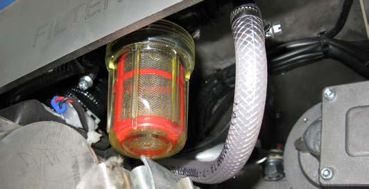
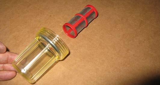
34 5.7 CLEANING THE DETERGENT SOLUTION (OR WATER FOR WASHING) FILTER 1. Ascertain that the wash-and-dry machine cannot move autonomously. 2. By acting on the wash-and-dry machine controls, lower the squeegee and the disc brush (or cylindrical brushes), then rotate the ignition key on 0 and extract it (see chapter Use). 3. Close the water/detergent solution flow tap (1, Figure 5-7) by acting on the right side of the washand-dry machine. 4. Unscrew and remove the filter transparent cover (2). 5. Remove the filter (3) from the transparent cover (4). 6. Clean the filter (3) and the transparent cover (4). 7. Replace the filter (3) in its transparent cover case (4). 8. Screw the filter transparent cover to its seat (2). 9. Open the tap (1). 10. Rotate the ignition key on I and wait for the squeegee and disc brush (or cylindrical brushes) lifting, then rotate the ignition key on 0 and extract it. 5-6

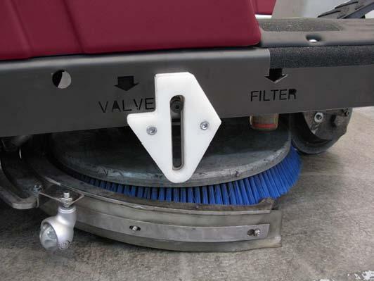
35 Figure

 of the brush, unscrew the ring nut (2) and recover the nozzle")
 in its case. 7.")
36 5.8 CLEANING THE NOZZLE AND FILTER DETERGENT SOLUTION SUPPLY TO THE DISC BRUSH 1. Ascertain that the wash-and-dry machine cannot move autonomously. 2. Remove the brush (See procedure in the related paragraph). 3. By acting on the coupling hub (1, Figure 5-8) of the brush, unscrew the ring nut (2) and recover the nozzle (3) and the gasket (4). 4. Remove the filter from its seat (5). 5. Clean the nozzle (3) and the filter (5). 6. Replace the filter correctly (5) in its case. 7. Place the nozzle (3) and the gasket (4) in their seat and then screw the ring nut (2). 8. Replace the brush (See the procedure in the related paragraph) Figure
. 3.")
37 5.9 CLEANING THE NOZZLE AND FILTER DETERGENT SOLUTION SUPPLY TO THE CYLINDRICAL BRUSHES 1. Ascertain that the wash-and-dry machine cannot move autonomously. 2. By acting on the wash-and-dry machine controls, lower the cylindrical brushes, then rotate the ignition key on 0 and extract it (see chapter Use). 3. By acting on the front part of the cylindrical brushholder head, unscrew the ring nut (1, Figure 5-9) and recover the nozzle (2) and the gasket (3). 4. Remove the filter from its seat (4). 5. Clean the nozzle (2) and the filter (4). 6. Replace the filter correctly (4) in its case. 7. Place the nozzle (2) and the gasket (3) in their seat and then screw the ring nut (1). 8. Rotate the ignition key on I and wait for the lifting of the cylindrical brushes, then rotate the ignition key on 0 and extract it CLEANING THE DETERGENT FEEDING SYSTEM (OPTIONAL) 1. Empty and clean the washing detergent tank, by acting as described in the related paragraph. 2. Put about one litre of clean water into the washing detergent tank. 3. Use the wash-and-dry machine by simulating the washing activity, for the time necessary to clean the detergent feeding system (15-30 minutes), by adjusting the clean water and detergent flows to the maximum values. 4. Finally, remove the residual water from the washing detergent tank. 5. If necessary, perform the other intended procedures After use of the wash-and-dry machine (See the related paragraph). Figure
38 5.11 BATTERY CHARGE Battery charge for wash-and-dry machines without on board battery charger CAUTION! Keep the batteries charged make their life last longer. CAUTION! When the batteries are discharged, recharge them as soon as possible, as that condition makes their life shorter. Check for battery charge at least once a week. CAUTION! For machines not equipped with on board battery charger, the battery charger must be appropriate for the battery installed on the machine. WARNING! Battery charging of WET batteries produces explosive hydrogen gas. Charge the batteries only in well-ventilated areas and far from naked flames. Do not smoke during battery charging. Keep the tank assembly open while recharging the battery. WARNING! Pay attention during battery recharging because there can be battery liquid leakages. The battery liquid is corrosive. If it comes in contact with the skin or eyes, rinse thoroughly with water and consult a physician. 1. Take the wash-and-dry machine to the area suited for recharging the batteries. 2. Ascertain that the wash-and-dry machine cannot move autonomously. Rotate the ignition key on 0 and extract it. 3. By acting of the rear side of the wash-and-dry machine, remove the left pin (1, Figure 5-10), then rotate it by half turn, and block it in the removed position. 4. Remove the right pin (2, Figure 5-10) and, carefully, remove completely the battery holder case (3) by the handles (4), then engage the pin (2) on the related locking hole of the extracted case. 5. Only for lead batteries (WET): check the correct electrolyte level in the batteries (7, Figure 5-10); if necessary, restore it through the stoppers (8). let all the stoppers (8) open for the next recharge. clean (if necessary) the upper surface of the batteries. 6. Check the suitability of the battery charger to be used by referring to the instructions of the battery charger itself. The nominal voltage of the battery charger must be equal to 24V. 7. Disconnect the connector of the batteries (5, Figure 5-10). 8. Connect the connector (6, Figure 5-10) to the external battery charger. 9. Connect the battery charger to the electrical network. The charge of the batteries has started. 10. At the end of the recharge, disconnect the battery charger from the electric network and the battery connector (6, Figure 5-10). 11. (only for lead batteries (WET)) Check the correct electrolyte level in the batteries, then close all the stoppers (8, Figure 5-10). 5-10
 and place the battery case into its seat, then engage")
 to the battery case. 15.")
39 12. Connect again the connector (5, Figure 5-10) to the connector (6). 13. Extract the pin (2) and place the battery case into its seat, then engage the pin (2) to the battery case itself. 14. Unblock and engage the pin (1) to the battery case. 15. The charge has ended Figure

40 Battery charge for wash-and-dry machines with on board battery charger (optional) 1. Take the wash-and-dry machine to the area suited for recharging the batteries. 2. Ascertain that the wash-and-dry machine cannot move autonomously. 3. By acting on the rear side of the wash-and-dry machine, remove the left pin (1, Figure 5-12), then rotate it by half turn, and block it in the removed position. 4. Remove the right pin (2, Figure 5-12) and, carefully, remove completely the battery holder case (3) by the handles (4), then engage the pin (2) on the related locking hole of the removed case. 5. Only for lead batteries (WET): check the correct electrolyte level in the batteries (7, Figure 5-12); if necessary, restore it through the stoppers (8). let all the stoppers (8) open for the next recharge. clean (if necessary) the upper surface of the batteries. 6. Connect the connector (5) to the electrical network, after checking that the nominal voltage of the network is that envisaged for the charge of the wash-and-dry machine (Refer to the technical data plate of the letter). The charge of the batteries has started. 9. (only for lead batteries (WET)) Check the correct electrolyte level in the batteries, then close all the stoppers (8, Figure 5-12). 10. Extract the pin (2, Figure 5-12) and place the battery case into its seat; then engage the pin (2) to the battery case itself. 11. Unblock and engage the pin (1, Figure 5-12) to the battery case. 12. The charge has ended. 1 2 Figure 5-11 & NOTE When the battery charger is connected to the network, all the functions of the wash-anddry machine are automatically excluded. 7. The charge has ended when on the display (1, Figure 5-11) appears 100 % and all the bars are full (2). 8. Disconnect the electrical connection (5, Figure 5-12) from the network. 5-12

41 Figure
, then rotate it by half turn, and block it in the removed position.")
42 5.12 CHECKING/REPLACING THE FUSES 1. Ascertain that the wash-and-dry machine cannot move autonomously. 2. Rotate the ignition key on 0 and extract it. 3. Disconnect the connector from the batteries, by acting as described further down. Remove the left pin (1, Figure 5-14), then rotate it by half turn, and block it in the removed position. Remove the right pin (2, Figure 5-14), then remove the battery holder case (3) by using the handles (4). Disconnect the connector of the batteries (5). 4. Raise the cover (5, Figure 5-15), remove the panel (1) by seizing it on the hold (3) and raising it to disengage it from the retainers (4). Close the cover (5). 5. Check / replace the fuses: 10A Fuse for protecting auxiliary services (2, Figure 5-15) 6. Place the panel into its seat (1, Figure 5-15) and engage the retainers (4). 7. Connect the connector of the batteries (5, Figure 5-14). 8. Replace the batteries case to its seat (3, Figure 5-14) and engage it to the retainer (2) and retainer (1) after unblocking it ASSEMBLY-DISASSEMBLY OF THE SQUEEGEE Disassembly 5. Remove the squeegee (1). Assembly 6. Assemble in the reverse order with respect to disassembly 1 2 Figure Ascertain that the wash-and-dry machine cannot move autonomously. 2. Rotate the ignition key on 0 and extract it. 3. By acting of the left side of the wash-and-dry machine, with the squeegee in raised position, move slightly the squeegee outwards (1, Figure 5-13), then loosen its fastening knob (2). 4. Disconnect the suction pipe (3, Figure 5-13) from the squeegee. 5-14

43 Figure Figure
44 5.14 ASSEMBLY-DISASSEMBLY OF THE DISC BRUSH Disassembly 1. Ascertain that the wash-and-dry machine cannot move autonomously. 2. Sit on the wash-and-dry machine seat and rotate the ignition key (1, Figure 5-16) on I, then wait for a few seconds so that on the display (3) appears caption (4) READY indicating that the wash-and-dry machine is ready for use. 3. Press the button (5, Figure 5-16) to release the brush and wait for a few seconds that the wash-and-dry machine releases the brush after activating it. 4. Rotate the ignition key (1, Figure 5-16) on 0 and then extract it. 5. Move slightly the squeegee (6, Figure 5-16) and recover the disc brush (7). Assembly 6. Ascertain that ignition key (1, Figure 5-16) is on Ascertain that the coupling hub of the disc brush is in the raised position. 8. Place the disc brush (7, Figure 5-16) below the wash-and-dry machine, by centring it on the coupling hub. 9. Sit on the seat and rotate the ignition key (1, Figure 5-16) on I, and wait for a few seconds so that on the display (3) appears caption (4) READY indicating that the wash-and-dry machine is ready for use. 10. Press the brush lowering and rotation (8, Figure 5-16) activation button. 11. Press slightly and only for an instant the pedal (2, Fig. R), by determining the lowering of the hub that will couple the brush. In case of non-coupling of the brush, get out of the wash-and-dry machine and reposition the brush on the coupling hub which will have remained lowered (therefore, the alignment operation will be facilitated). 12. Repeat the operations described in the previous points 9, 10 and Rotate the ignition key (1, Figure 5-16) on 0 and then extract it Figure
.")
 by disengaging the supports (2) from the cylindrical brushes (3). 5. Extract the cylindrical brushes (3, Figure 5-19).")
45 5.15 CYLINDRICAL BRUSHES ASSEMBLY-DISASSEMBLY Disassembly 1. Ascertain that the wash-and-dry machine cannot move autonomously. 2. By operating on the wash-and-dry machine controls, lower the cylindrical brushes then rotate the ignition key on 0 and extract it (see the chapter Use). 3. By operating on the right side of the wash-and-dry machine, release the retainers and cam (1, Figure 5-17). 4. Remove the cover (1, Figure 5-18) by disengaging the supports (2) from the cylindrical brushes (3). 5. Extract the cylindrical brushes (3, Figure 5-19). 3 2 Figure Figure 5-17 Figure
 by ensuring to engage their pentagonal seat (2) in the related hubs")
46 Assembly 6. Place the cylindrical brushes in their seat (1, Figure 5-20) by ensuring to engage their pentagonal seat (2) in the related hubs (3). 7. Proceed with the assembly by operating in the reverse order with respect to disassembly Figure
SERVICE MANUAL (2)
") Terra 128B - 132B SERVICE MANUAL 146 0721 000(2)2003-04 INDEX GENERAL INFORMATION 3 MACHINE LIFTING 3 MACHINE TRANSPORTATION 3 OTHER AVAILABLE MANUALS 3 SAFETY - ACCIDENT PREVENTION 4 GENERAL SAFETY RULES
Terra 128B - 132B SERVICE MANUAL 146 0721 000(2)2003-04 INDEX GENERAL INFORMATION 3 MACHINE LIFTING 3 MACHINE TRANSPORTATION 3 OTHER AVAILABLE MANUALS 3 SAFETY - ACCIDENT PREVENTION 4 GENERAL SAFETY RULES
Vantage 17. antage 17 Battery. Battery / Cable. Operator s Manual. Service Manual
 Vantage 17 Battery / Cable antage 17 Battery Operator s Manual Service Manual Form No. 9097182000-11/2009 SERVICE MANUAL ENGLISH TABLE OF CONTENTS GENERAL INFORMATION... 3 GENERAL INFORMATION... 3 MACHINE
KENT/Euroclean MODELS: (2)
") Razor 17B - 20B - 20BT SERVICE MANUAL KENT/Euroclean MODELS: 908 7010 020-908 7011 020-908 7025 020 08603953(2)2003-09 INDEX GENERAL INFORMATION 3 MACHINE LIFTING 3 MACHINE TRANSPORTATION 3 OTHER AVAILABLE
Razor 17B - 20B - 20BT SERVICE MANUAL KENT/Euroclean MODELS: 908 7010 020-908 7011 020-908 7025 020 08603953(2)2003-09 INDEX GENERAL INFORMATION 3 MACHINE LIFTING 3 MACHINE TRANSPORTATION 3 OTHER AVAILABLE
Razor Plus 24D-26D-28D
 Razor Plus 24D-26D-28D SERVICE MANUAL KENT/Euroclean models: 908 7041 020-908 7038 020-908 7039 020 909 5485 000(1)2004-08 GENERAL INFORMATION... 3 MACHINE LIFTING... 3 MACHINE TRANSPORTATION... 3 OTHER
Razor Blade 26D/28D/28C
 Razor Blade 26D/28D/28C Kent models: 908 7099 020-908 7100 020-908 7101 020 Simple. Clean. 909 6510 000(3) 2007-12 ENGLISH TABLE OF CONTENTS GENERAL INFORMATION... 3 CONVENTIONS... 3 MACHINE LIFTING...
BA 450/530 BA 5321 SERVICE MANUAL
 BA 450/530 BA 5321 SERVICE MANUAL 08812876(1)2002-01 Nilfisk-Advance Italia S.p.A Località Novella Terza 26862 Guardamiglio (Lodi) Italia www.nilfisk-advance.com Phone: +39 0377 451124 Fax: +39 0377 51443
Razor SV17 Razor E17. Simple. Clean. SERVICE MANUAL Kent models: (4)
") Razor SV17 Razor E17 Kent models: 908 7113 020 908 7112 020 Simple. Clean. 909 6577 000(4)2009-11 ENGLISH 2 909 6577 000(4)2009-11 Razor SV17 - Razor E17 ENGLISH TABLE OF CONTENTS GENERAL INFORMATION...
Razor SV17 Razor E17 Kent models: 908 7113 020 908 7112 020 Simple. Clean. 909 6577 000(4)2009-11 ENGLISH 2 909 6577 000(4)2009-11 Razor SV17 - Razor E17 ENGLISH TABLE OF CONTENTS GENERAL INFORMATION...
NILFISK BA 500 Service Manual
 NILFISK BA 500 Service Manual Model 66324400 12/94 Form Number 043023 TABLE OF CONTENTS Batteries...21 Brush Drive Belt Adjustment Or Replacement...7 Brush Drive Motor - Carbon brush Inspection... 8 Brush
FLOORMASTER 18B OPERATING & MAINTENANCE READ THIS BOOK
 FLOORMASTER 18B INTRODUCTION OPERATING & MAINTENANCE INSTRUCTIONS This operator s book has important information for the use and safe operation of this machine. Read this book carefully before starting
COLLECTOR 37 USER MANUAL
 COLLECTOR 37 USER MANUAL A B E F C D H 2 G ENGLISH INTRODUCTION POWERBOSS,Inc. leaders in the production of sweeping machines, are pleased to welcome you as an owner of the Collector 37 sweeper machine.
Terra TM 4300B. SERVICE MANUAL Advance model: (2)
") Terra TM 4300B Advance model: 908 4309 010 1463200000(2)2008-07 INDEX ENGLISH INDEX GENERAL INFORMATION... 3 MACHINE LIFTING... 3 MACHINE TRANSPORTATION... 3 PUSHING OR TOWING THE MACHINE... 3 OTHER REFERENCE
Terra TM 4300B Advance model: 908 4309 010 1463200000(2)2008-07 INDEX ENGLISH INDEX GENERAL INFORMATION... 3 MACHINE LIFTING... 3 MACHINE TRANSPORTATION... 3 PUSHING OR TOWING THE MACHINE... 3 OTHER REFERENCE
Electronic Service Manuals
 Electronic Service Manuals This electronic document is provided as a service to our customers. We do not create the contents of the information contained in this document. Should you have detailed questions
HOT WASHER MODEL NO: KING 125 OPERATION & MAINTENANCE INSTRUCTIONS PART NO: LS1009
 HOT WASHER MODEL NO: KING 125 PART NO: 7320170 OPERATION & MAINTENANCE INSTRUCTIONS LS1009 INTRODUCTION Thank you for purchasing this Hot Washer. This machine is a portable, high pressure power washer,
S9 SWEEPER PARTS MANUAL
 S9 SWEEPER PARTS MANUAL Clemas & Co. Unit 5 Ashchurch Business Centre, Alexandra Way, Tewkesbury, Gloucestershire, GL20 8NB. Tel: 01684 850777 Fax: 01684 850707 Email: info@clemas.co.uk Web: www.clemas.co.uk
MP V 8A Electronic Smart Charger. Instruction and Information Manual
 MP7428 12V 8A Electronic Smart Charger Instruction and Information Manual In order to ensure correct and safe usage of your battery charger, you should read these instructions carefully. Please retain
USER MANUAL. Ride-on Scrubbers. Model # Serial No.# READ USER MANUAL CAREFULLY BEFORE USE. Please fill out & return your warranty card
 Ride-on Scrubbers USER MANUAL READ USER MANUAL CAREFULLY BEFORE USE Please fill out & return your warranty card Model # Serial No.# VIPER INDUSTRIAL ESTATE LIANG BIAN, LIAO BU DONGGUAN, GUANGDONG CHINA
GENERAL NOTES. This guide has been edited for the CONSUMER according to directive CE89/392 and its ensuing amendments.
 GENERAL NOTES This guide has been edited for the CONSUMER according to directive CE89/392 and its ensuing amendments. Carefully read the notes contained in this guide since they provide with important
SC450. Service Manual. Advance SC450, Nilfisk SC450, English Form No
 SC450 Service Manual Advance SC450, 9087331020 Nilfisk SC450, 9087330020 English 2012-11 Form No. 9099600000 Index 2 Index Index 2 General Information 4 Machine General Description 4 Service Manual Purpose
INSTRUCTION MANUAL ANGLE GRINDER PT W
 INSTRUCTION MANUAL ANGLE GRINDER PT50360 4½ INCHES 120V 60Hz 600W 5A 12,000 rpm C US Note : Before operating this tool, read this manual and follow all safety rules and operating instructions. This electric
Smart Charger 12-24V 60A, 1600W
 Smart Charger 12-24V 60A, 1600W Installation and User Manual Advanced Battery Chargers Table of contents Important SC 60A General SC60A 2 General 2 Installation 3 Operations 4 Safety Instructions 5 Troubleshooting
OPERATING MANUAL 18V Ni-Cd Battery Pack
 OPERATING MANUAL 18V Ni-Cd Battery Pack 054-3105-6 Toll-free Helpline : 1-800-689-9928 IMPORTANT : Read this Operating Manual carefully before using the charger. Pay close attention to all Safety Instructions,
PAC 600 PAC 800 PAC 800 comfort
 PAC 600 PAC 800 PAC 800 comfort Installation and User Manual Advanced Battery Chargers Table of contents POWERFINN PAC 600/800...2 General... 2 Installation...3 Operations... 4 Safety Instructions... 5
SR 1300 B/ECO. OPERATOR MANUAL Advance MODELS , FORM No (1)00-03
00-03") SR 1300 B/ECO OPERATOR MANUAL Advance MODELS 908 3013 010, 908 3301 010 FORM No. (1)00-03 INDEX INTRODUCTION / GENERAL INFORMATION... 1 UNPACKING... 2 TECHNICAL DATA... 3 DESCRIPTION OF COMMANDS AND CONTROL
SR 1300 B/ECO OPERATOR MANUAL Advance MODELS 908 3013 010, 908 3301 010 FORM No. (1)00-03 INDEX INTRODUCTION / GENERAL INFORMATION... 1 UNPACKING... 2 TECHNICAL DATA... 3 DESCRIPTION OF COMMANDS AND CONTROL
Battery Sweeper Operator Manual
 S8 Battery Sweeper Operator Manual Model Part No.: MS85004 MS85904 UK 9001217 Rev. 01 (12-05) TENNANT N.V. Industrielaan 6 5405 AB P.O. Box 6 5400 AA Uden-The Netherlands europe@tennantco.com www.tennantco.com
60V RECHARGEABLE LITHIUM-ION BATTERY
 60V RECHARGEABLE LITHIUM-ION BATTERY LB60A00/LB60A03/LB60A01/LB60A02 Owner s Manual TOLL-FREE HELPLINE: 1-855-345-3934 www.greenworkstools.com Read all safety rules and instructions carefully before operating
82V LITHIUM-ION BATTERY CHARGER GC 400
 82V LITHIUM-ION BATTERY CHARGER GC 400 (2907302) Owner s Manual TOLL-FREE HELPLINE: 1-855-470-4267 www.greenworkstools.com/82v-commercial/ Read all safety rules and instructions carefully before operating
i-mop xxl Service Manual
 i-mop xxl Service Manual Jan.2018 Warning: read the instructions before using the machine 1/64 SUMMARY CHAPTER 1 GENERAL INFORMATION... 4 1.1 CONVENTIONS... 4 1.2 WORKING ON THE MACHINE... 4 1.3 TRANSPORTING
INSTRUCTION MANUAL. 12V Ride on ATV Quad SKY SKY SKY3754. Ver. 4
 Ver. 4 INSTRUCTION MANUAL 2V Ride on ATV Quad SKY207 + SKY2580 + SKY3754 Charge for 8 hrs before initial use. After initial charge, follow the normal recommended charging time. bestchoiceproducts.com SAFETY
Light condition and operation Windshield glass condition Wiper blade condition Paint condition and corrosion Fluid leaks Door and hood lock condition
 GENERAL CHECKS Engine Compartment The following should be checked regularly: Engine oil level and condition Transmission fluid level and condition Brake fluid level Clutch fluid level Engine coolant level
INSTRUCTION MANUAL. Kids Ride-On Motorcycle SKY Ver. 3
 INSTRUCTION MANUAL Kids Ride-On Motorcycle Ver. 3 SKY785 + 89 Pg. 2 Thank you for choosing us! Since 2002, Best Choice Products has been bringing customers high-quality products at the absolute lowest
C3 Operating Instructions
 Version 3.1 Stand 09.2014 Robert Bosch (Australia) Pty. Ltd. 1555 Centre Road Clayton, Victoria 3168 C3 Operating Instructions For further information please contact Bosch at: Australia 1300 30 70 40 www.boschautoparts.com.au
INSTRUCTION MANUAL. Ride-On Convertible Truck SKY SKY SKY2581. Ver. 2
 Ver. 2 INSTRUCTION MANUAL Ride-On Convertible Truck SKY2069 + SKY2338 + SKY2581 SAFETY Please retain these instructions for future reference. This vehicle must be assembled by an adult who has read and
SW900. Service Manual. Advance SW900 Battery Nilfisk SW900 Battery Nilfisk SW900 Petrol
 SW900 Service Manual Advance SW900 Battery 9084112010 Nilfisk SW900 Battery - 9084110010 Nilfisk SW900 Petrol - 9084111010 English 2013-11 Form No. 1465376000 Contents ii Contents General Information 5
Turbo M Series onboard charger
 Turbo M Series onboard charger Operation Manual Model # Output Bank Max. Output Turbo M106 1 6 Amps Turbo M108 1 8 Amps Turbo M208 2 8 Amps Turbo M212 2 12 Amps Turbo M220 2 20 Amps Turbo M230 2 30 Amps
A B 0 0 C D E 6 7 G F F H 8 9 K M O O L N I J 1
 1 2 1 5 4 3 2 2 1 6 3 8 7 1 9 4 C A B 5 0 0 D E 6 G 7 F F H 8 K 9 M O O I J L N 1 GENERAL OPERATIONAL PRECAUTIONS 1. Keep work area clean. Cluttered areas and benches invite accidents. 2. Avoid dangerous
SC351. Service Manual. Advance SC351, Nilfisk SC351, English Form No Revised 2013/11
 SC351 Service Manual Advance SC351, 9087342020 Nilfisk SC351, 9087340020-9087341020 English 2013-05 Form No. 9099876000 Revised 2013/11 Table of Contents 2 Table of Contents General Information 4 Machine
OWNER'S MANUAL WARNING DANGER. Propane cylinders sold separately. The propane cylinder must be disconnected when this firebowl is not use.
 OWNER'S MANUAL READ BEFORE USE! Model No.: BH5003-3 Style No.: 66646 For Outdoor Use Only! Use Propane Gas Only! Propane cylinders sold separately. USE PROPANE GAS ONLY! -Do not store or use gasoline or
Electric Car User Manual
 Electric Car User Manual The owner s manual contains important safety information as well as assembly, use and maintenance instructions. The Ride-on Car must be assembled by an adult who has read and understands
User Manual of Bagibike Electric Bicycles
 User Manual of Bagibike Electric Bicycles Model: Bagibike B16. http://www.bagibike.com Page 1 FOREWORD The following operation manual is a guide to assist you. This manual is not a complete document on
INSTRUCTION MANUAL. Kids Ride-On Dirt Bike with Training Wheels SKY SKY3487. Ver. 2
 Ver. 2 INSTRUCTION MANUAL Kids Ride-On Dirt Bike with Training Wheels SKY3486 + SKY3487 Pg. 2 Thank you for choosing us! Since 2002, Best Choice Products has been bringing customers high-quality products
INSTRUCTION MANUAL. Rescue Ride-On SKY Ver. 5
 Ver. 5 INSTRUCTION MANUAL Rescue Ride-On SKY2886 + 3995 SAFETY Please retain these instructions for future reference. This vehicle must be assembled by an adult who has read and understood the instructions
Cordless Screwdriver
 ENGLISH Cordless Screwdriver MODEL 6796D MODEL 6796FD MODEL 6797D MODEL 6797FD MODEL 6798D MODEL 6798FD 00260 I N S T R U C T I O N M A N U A L WARNING: For your personal safety, READ and UNDERSTAND before
Cordless Rechargeable Saw Instructions for Use
 Technical data Voltage: DC 10.8V Weight: 1.25Kg Stroke rate: 0-2100/min Stroke: 15mm Cutting capacity: max diameter in wood 80mm / in soft metal 7mm Charging time: Between 5.0-5.5 Hours Battery: 1.3Ah
Rescue Pac. Please read and fully understand the instructions in this manual before operation. Keep this manual safe for future reference
 Please dispose of Packaging for the product in a responsible manner. It is suitable for recycling. Help to protect the environment, take the packaging to the local amenity tip and place into the appropriate
Operator s Manual Libro SERVICE de Instrucciones Manuel d utilisation
 Operator s Manual Libro SERVICE de Instrucciones MNUL Manuel d utilisation RED THIS BOOK LE ESTE MNUL LISEZ CE MNUEL EN ES FR English (2-33) Español (34-65) Français (66-98) Form No. 9097067000-04/2008
Parts missing or damaged? Questions? Toll-free Helpline
 INSTRUCTION MANUAL Multi-Charger 054-3107-2 Parts missing or damaged? Questions? Toll-free Helpline 1-800-689-9928 Important: Carefully read this Instruction Manual before using this tool. Pay close attention
Disc Grinder Model G 18MR G 23MR G 23MRU
 Disc Grinder Model G 18MR G 23MR G 23MRU Handling instructions G23MR NOTE: Before using this Electric Power Tool, carefully read through these HANDLING INSTRUCTIONS to ensure efficient, safe operation.
User s Manual. Automatic Switch-Mode Battery Charger
 User s Manual Automatic Switch-Mode Battery Charger IMPORTANT Read, understand, and follow these safety rules and operating instructions before using this battery charger. Only authorized and trained service
8 Step Fully Automatic Intelligent BATTERY CHARGER 12V 5A USER S MANUAL. Charges & Maintains. Flooded (WET), MF, VRLA, AGM, GEL & Calcium batteries
, MF, VRLA, AGM, GEL & Calcium batteries") 8 Step Fully Automatic Intelligent BATTERY CHARGER 12V 5A Charges & Maintains Flooded (WET), MF, VRLA, AGM, GEL & Calcium batteries USER S MANUAL 5 User s Manual And Guide To Professional Battery Charging
8 Step Fully Automatic Intelligent BATTERY CHARGER 12V 5A Charges & Maintains Flooded (WET), MF, VRLA, AGM, GEL & Calcium batteries USER S MANUAL 5 User s Manual And Guide To Professional Battery Charging
INSTRUCTION MANUAL. Ride-On Convertible SKY907 + SKY908 + SKY2308. Ver. 3
 Ver. 3 INSTRUCTION MANUAL Ride-On Convertible SKY907 + SKY908 + SKY2308 SAFETY Please retain these instructions for future reference. This vehicle must be assembled by an adult who has read and understood
Butterfly Valve Type 58 (PDCPD)
") Serial No. H-V074-E Butterfly Valve Type 58 (PDCPD) 700mm (28 ) User s Manual Contents (1) Be sure to read the following warranty clauses of our product 1 (2) General operating instructions 2 (3) General
Serial No. H-V074-E Butterfly Valve Type 58 (PDCPD) 700mm (28 ) User s Manual Contents (1) Be sure to read the following warranty clauses of our product 1 (2) General operating instructions 2 (3) General
20V Lithium-Ion Battery Pack
 20V Lithium-Ion Battery Pack 252-8034 OPERATOR S MANUAL CAUTION: To Reduce The Risk Of Injury, User Must Read And Understand Operator s Manual. Save These Instructions For Future Reference. For questions
6V MASERATI GRANTURISMO MC STRADALE OWNER S MANUAL KT1252TR. Age: 3-7 yrs Weight: Maximum 77 lbs (35 Kgs) Max Speed: 2.5 MPH Battery: 6V7AH
 Max Speed: 2.5 MPH Battery: 6V7AH") 6V MASERATI GRANTURISMO MC STRADALE KT1252TR OWNER S MANUAL Age: 3-7 yrs Weight: Maximum 77 lbs (35 Kgs) Max Speed: 2.5 MPH Battery: 6V7AH Maserati logo and model designations are registered trademarks
6V MASERATI GRANTURISMO MC STRADALE KT1252TR OWNER S MANUAL Age: 3-7 yrs Weight: Maximum 77 lbs (35 Kgs) Max Speed: 2.5 MPH Battery: 6V7AH Maserati logo and model designations are registered trademarks
Audi R8. Ride-on Car 5F62630 OWNER S MANUAL. Keep instructions for future reference
 Audi R8 Ride-on Car 5F62630 OWNER S MANUAL Keep instructions for future reference 1 Safety The owner s manual contains assembly, use and maintenance instructions. The vehicle must be assembled by an adult
Marlin Bath Lift BLM-8200 WARNING! Read ALL instructions before using this product!
 Marlin Bath Lift BLM-8200 www.inspiredbydrive.com WARNING! Read ALL instructions before using this product! PRODUCT DESCRIPTIONS Your Marlin Bath Lift has been built to the highest standards of quality
1/2 HP SUMP PUMP OWNER'S MANUAL
 TM 1/2 HP SUMP PUMP OWNER'S MANUAL WARNING: Read carefully and understand all INSTRUCTIONS before operating. Failure to follow the safety rules and other basic safety precautions may result in serious
Vehicle battery BATTERY WARNING SYMBOLS BATTERY CARE
 Vehicle battery BATTERY WARNING SYMBOLS On the battery label, the warning signs are as follows: BATTERY CARE No smoking, no naked flames, no sparks. The battery may emit explosive gas. Keep away from children
ORIGINAL INSTRUCTIONS
 OPERATION & MAINTENANCE INSTRUCTIONS CBB200 Shown here BUFFER/POLISHER MODEL NO: CBB150, CBB200 PART NO: 6500485, 6500490 ORIGINAL INSTRUCTIONS LS0818 - ISS 1 INTRODUCTION Thank you for purchasing this
(R86049) WARNING: To reduce the risk of injury, the user must read and understand the operator s manual before using this product.
 WARNING: To reduce the risk of injury, the user must read and understand the operator s manual before using this product.") OPERATOR S MANUAL 12 VOLT LITHIUM-ION BATTERY CHARGER 140446001 (R86049) Your charger has been engineered and manufactured to our high standards for dependability, ease of operation, and operator safety.
OPERATOR S MANUAL 12 VOLT LITHIUM-ION BATTERY CHARGER 140446001 (R86049) Your charger has been engineered and manufactured to our high standards for dependability, ease of operation, and operator safety.
TABLE OF CONTENTS UNPACKING/DELIVERY... 3
 ENGLISH TLE OF CONTENTS INTRODUCTION... 2 MNUL PURPOSE ND CONTENTS... 2 TRGET... 2 HOW TO KEEP THIS MNUL... 2 DECLRTION OF CONFORMITY... 2 IDENTIFICTION DT... 2 OTHER REFERENCE MNULS... 2 SPRE PRTS ND
Pump Manual. Model Numbers: SP240VDFS57LPM SP240VDFS80LPM. Product Names: Digital Refueling Station - 57 L/min Digital Refueling Station - 80 L/min
 Pump Manual Model Numbers: SP240VDFS57LPM SP240VDFS80LPM Product Names: Digital Refueling Station - 57 L/min Digital Refueling Station - 80 L/min Copyright: Scintex Fuel Depot 2012[Type text] Page 1 WARNING:
User Manual. H20 Walk-Behind Scrubber Disc Traction Drive
 User Manual H20 Walk-Behind Scrubber Disc Traction Drive This manual is furnished with each new MINUTEMAN H20. This provides the necessary operating and preventive maintenance instructions. Operators must
AUTOMATIC BURNISHER MODEL FURY 21 HSB
 AUTOMATIC BURNISHER MODEL FURY 21 HSB INTRODUCTION OPERATING & MAINTENANCE INSTRUCTIONS This operator s book has important information for the use and safe operation of this machine. Read this book carefully
CAUTION-ELECTRICALLY OPERATED PRODUCT:
 CAUTION-ELECTRICALLY OPERATED PRODUCT: NOT RECOMMENDED FOR CHILDREN UNDER 8 YEARS OF AGE, AS WITH ALL ELECTRIC PRODUCTS, PRECAUTIONS SHOULD BE OBSERVED DURING HANDLING AND USE TO PREVENT ELECTRIC SHOCK,INPUT:120V
Electronic Service Manuals
 Electronic Service Manuals This electronic document is provided as a service to our customers. We do not create the contents of the information contained in this document. Should you have detailed questions
12 amp RMS Battery Charger
 12 amp RMS Battery Charger 83-5000-12 If faults cannot be remedied, contact the Helpline on 020 8391 6767 helpline@hilka.co.uk Manufactured under license by Hilka Pro Imports GUARANTEE This product is
80 Litre Suction Oil Drainer With Inspection Chamber
 Please dispose of packaging for the product in a responsible manner. It is suitable for recycling. Help to protect the environment, take the packaging to the local amenity tip and place into the appropriate
USE and MAINTENANCE INSTRUCTION MANUAL AZ3 HTE2 AZ3 HTE2 HVLP GRAVITY. SPRAY GUN Series. en it fr es pt de se
 USE and MAINTENANCE INSTRUCTION MANUAL AZ3 HTE2 AZ3 HTE2 HVLP GRAVITY SPRAY GUN Series en it fr es pt de se TECHNICAL DATA Technical AZ3 HTE2 AZ3 HTE2 HVLP 1.0 80 180 1.3 10-15HTE 140 200 240 1.5 2.0 160
PNEUMATIC PUMP Series
 PNEUMATIC PUMP Series 3103... User and Maintenance Manual Original text translation TABLE OF CONTENTS 1. INTRODUCTION 2. GENERAL DESCRIPTION 3. PRODUCT-MACHINE IDENTIFICATION 4. TECHNICAL CHARACTERISTICS
MULTIVOLTAGE PORTABLE BATTERY CHARGER MVM
 _ M MULTIVOLTAGE PORTABLE BATTERY CHARGER MVM User's MANUAL Code: MVM Version: 01-BF Date: OCT 2005 Page 1/10 _ 1. INTRODUCTION Before starting to use your Energic plus MVM battery charger, please take
BATTERY BOOSTER/CHARGER MODEL NO: DIGICAR 600
 BATTERY BOOSTER/CHARGER MODEL NO: DIGICAR 600 PART NO: 6261200 OPERATION & MAINTENANCE INSTRUCTIONS LS0815 INTRODUCTION Thank you for purchasing this CLARKE Battery booster / charger which is suitable
CORDLESS TACKER MODEL NO: CCT48 OPERATION & MAINTENANCE INSTRUCTIONS PART NO: LS0414
 CORDLESS TACKER MODEL NO: CCT48 PART NO: 6485070 OPERATION & MAINTENANCE INSTRUCTIONS LS0414 INTRODUCTION Thank you for purchasing this CLARKE product. Before attempting to use this product, please read
SUBMERSIBLE DIRTY WATER PUMP
 FOR USE WITH A 110V SUPPLY ONLY SUBMERSIBLE DIRTY WATER PUMP MODEL NO: DWP210A PART NO: 7230102 OPERATION & MAINTENANCE INSTRUCTIONS LS0115 INTRODUCTION Thank you for purchasing this CLARKE Submersible
AIR-COOLED DIESEL GENERATOR OWNERʼS MANUAL. This manual contains important safety information. TDG2500E TDGW7000E TDG7000SE TDG4500E
 AIR-COOLED DIESEL GENERATOR OWNERʼS MANUAL This manual contains important safety information. TDG2500E TDGW7000E TDG7000SE TDG4500E TDG8000-3 TDG7000SE-3 TDG7000E TDG8000E TDGW7000SE TDG7000E3 TDGW8000E
Tooling Assistance Center
 Safeguards are designed into this application equipment to protect operators and maintenance personnel from most hazards during equipment operation. However, certain safety precautions must be taken by
AUTOMATIC BATTERY CHARGER AUTOMATISCHES BATTERIELADEGERÄT CHARGEUR DE BATTERIE AUTOMATIQUE AUTOMATISCHE ACCULADER 12A RMS (8A DC) MCH12A
 MCH12A") AUTOMATIC BATTERY CHARGER AUTOMATISCHES BATTERIELADEGERÄT CHARGEUR DE BATTERIE AUTOMATIQUE AUTOMATISCHE ACCULADER 12A RMS (8A DC) MCH12A Suitable for all type of 12V lead acid, sealed, leisure and gel
AUTOMATIC BATTERY CHARGER AUTOMATISCHES BATTERIELADEGERÄT CHARGEUR DE BATTERIE AUTOMATIQUE AUTOMATISCHE ACCULADER 12A RMS (8A DC) MCH12A Suitable for all type of 12V lead acid, sealed, leisure and gel
RAUTOOL G2 BATTERY HYDRAULIC TOOL KIT PRODUCT INSTRUCTIONS. Construction Automotive Industry
 RAUTOOL G2 BATTERY HYDRAULIC TOOL KIT PRODUCT INSTRUCTIONS www.rehau.com Construction Automotive Industry TABLE OF CONTENTS Safety Information... 3 Items Supplied............................................4
INSTRUCTION MANUAL. Maserati Alfieri Ride-On SKY SKY4735. Ver. 1
 INSTRUCTION MANUAL Maserati Alfieri Ride-On Ver. 1 SKY4734 + SKY4735 Charge item 8 to 12 hours before initial use. After initial charge, follow the normal recommended charging time. bestchoiceproducts.com
THIS PRODUCT IS FOR PROFESSIONAL LABORATORY USE ONLY USER'S MANUAL. WELLS ENGINE UNIT 230 VOLT Product No. U905, U906, U907, U908
 DENTAL, INC. TECHNICAL BULLETIN U807-022510 5860 FLYNN CREEK ROAD READ ALL INSTRUCTIONS P.O. BOX 106 BEFORE PROCEEDING COMPTCHE, CALIFORNIA, U.S.A. 95427 SAVE THIS FOR FUTURE REFERENCE THIS PRODUCT IS
Step1: Battery and Speaker Assembly Step 2: Pump and Battery Installation Step 3: Setting Up Your Fountain 6 Troubleshooting and Maintenance
 Owner s Manual Contents Step1: Battery and Speaker Assembly 1 Step 2: Pump and Battery Installation 3 Step 3: Setting Up Your Fountain 6 Fill Your Fountain 7 Operating Your Fountain 7 Troubleshooting and
BATTERY BOOSTER/CHARGER MODEL NO: DIGICAR 900
 BATTERY BOOSTER/CHARGER MODEL NO: DIGICAR 900 PART NO: 6261205 OPERATION & MAINTENANCE INSTRUCTIONS LS0715 INTRODUCTION Thank you for purchasing this CLARKE Battery booster / charger which is suitable
Model #: ES320 Floor Scrubber Traction Driven E320QP E320CE E320QPIW OPERATION SERVICE PARTS CARE
 ES320 Floor Scrubber Traction Driven Model #: E320QP E320CE E320QPIW OPERATION SERVICE PARTS CARE TABLE OF CONTENTS IMPORTANT SAFETY INSTRUCTIONS...1 FOR SAFETY DURING OPERATION:...1 FOR SAFETY WHEN SERVICING
FJC, Inc. Part # V BATTERY Charger/Maintainer INSTRUCTION MANUAL SAFETY WARNINGS AND PRECAUTION
 FJC, Inc. Part # 52020 12V BATTERY Charger/Maintainer INPUT: 110V AC 60Hz OUTPUT: 6/12V DC 2A INSTRUCTION MANUAL SAFETY WARNINGS AND PRECAUTION CAUTION: TO PREVENT BATTERY DAMAGE: DO NOT USE on gel batteries
User Manuel. Titan Hummer XL
 User Manuel Titan Hummer XL Dear User, Tzora Active Systems Ltd. thanks you for choosing the Titan Hummer-XL and wishes you safe and enjoyable journeys. For proper operation and to maintain the scooter
Cordless Sweeper. OWNER S MANUAL Model: CFT Volt DC. Made Exclusively for ALDI Inc. Batavia, IL.,
 Cordless Sweeper OWNER S MANUAL Model: CFT25 4.8 Volt DC Made Exclusively for ALDI Inc. Batavia, IL., 60510-1477 CFT25 ONE (1) YEAR LIMITED WARRANTY This product is warranted to be free from defects in
4. TECHNICAL SPECIFICATIONS
 1. SAFETY/WARNING 2. FIRST AID Before using the SCA solar maintenance battery chargers ensure the instructions have been read and understood. The SCA solar maintenance battery chargers are not intended
GATE VALVES. Type P (Standard: Plug) Type S (Soft Seal) Contents. (1) Be sure to read the following warranty clauses of our product 1
 Type S (Soft Seal) Contents. (1) Be sure to read the following warranty clauses of our product 1") Serial No. H-V011-E-12 GATE VALVES Type P (Standard: Plug) Type S (Soft Seal) Contents (1) Be sure to read the following warranty clauses of our product 1 User s Manual (2) General operating instructions
Serial No. H-V011-E-12 GATE VALVES Type P (Standard: Plug) Type S (Soft Seal) Contents (1) Be sure to read the following warranty clauses of our product 1 User s Manual (2) General operating instructions
Installation, Operation & Maintenance Manual
 Installation, Operation & Maintenance Manual Picture may differ from your specific application For Pro-Fill kits with part numbers beginning in BG BL-175 9-20-13 General Information & Precautions This
 IU0U automatic charger Read these instructions carefully before the installation and commissioning and keep them in a safe place. Pass it on to the buyer in case of the further sale of the system. Contents
18V CORDLESS STAPLER/NAILER
 18V CORDLESS STAPLER/NAILER MODEL NO: CONSN18LI PART NO: 6487055 OPERATION & MAINTENANCE INSTRUCTIONS LS1213 INTRODUCTION Thank you for purchasing this CLARKE product. Before attempting to use this product,
TBE-700. Operation, Safety and Maintenance Manual. Stainless Steel Weld Cleaning System. Ensitech Pty Ltd
 Stainless Steel Weld Cleaning System Operation, Safety and Maintenance Manual TBE-700 TBE-700 Instruction Manual Oct 2013 (USA) FOREWORD FOREWORD This manual is a very important tool! Keep it with the
Trench Filler for Compact Utility Loaders
 Form No. 3353-608 Rev A Trench Filler for Compact Utility Loaders Model No. 22472 260000001 and Up Operator s Manual Register your product at www.toro.com Original Instructions (EN) Contents Page Introduction................................
USER'S GUIDE 9151 SERIES V
 USER'S GUIDE 9151 SERIES 220-240 V 2 Thank You 3 Safety Instructions 4 Product View 4-5 Assembly 5 Operations 6 Maintenance and Care 7 Troubleshooting 7 Replacement Parts 8 Warranty 8 Consumer Care Thanks
FSG175 FENCE STAPLE GUN
 Kencove Farm Fence Supplies 344 Kendall Rd Blairsville, PA 15717 1-800-KENCOVE sales@kencove.com www.kencove.com OPERATING MANUAL FSG175 FENCE STAPLE GUN To reduce the risk of possible injury, read the
SIP Direct Drive Oil-Lube Air Compressors - Operating & Maintenance Instructions
 SIP Direct Drive Oil-Lube Air Compressors - Operating & Maintenance Instructions Please read and fully understand the instructions in this manual before operation. Keep this manual safe for future reference.
OPERATING INSTRUCTIONS. Note: 6V Charging. Requires Manual Shut Off.
 Requires Manual Shut Off. 6 / 2 AMP,, DUAL RATE BATTER TTERY CHARGER 45005 OPERATING INSTRUCTIONS E224783 E224783 Note: 6V Charging Due to continuing improvements, actual product may differ slightly from
before serial number 2214
 before serial number 2214 Contents Page Safety Rules... 3 Pre-operational & Safety Inspection... 4 Operating Instructions... 6 Transport... 12 Maintenance & Routine Service... 12 Specifications... 14 SAFETY
Operating Instructions (EN) MODELS:
 MODELS:") Operating Instructions (EN) MODELS: 30'' Disk 34'' Disk 9'' Cylindrical 33'' Cylindrical Read these Instructions before using the machine. Read these Safety Messages before using the machine. Scan With
Operating Instructions (EN) MODELS: 30'' Disk 34'' Disk 9'' Cylindrical 33'' Cylindrical Read these Instructions before using the machine. Read these Safety Messages before using the machine. Scan With
Cordless High Speed Drill
 ENGLISH Cordless High Speed Drill MODEL 6503D 00039 I N S T R U C T I O N M A N U A L WARNING: For your personal safety, READ and UNDERSTAND before using. SAVE THESE INSTRUCTIONS FOR FUTURE REFERENCE.
KMR 1200 B (06/99)
") 1.891-104 5.951-590 (06/99) www.karcher.com Deutsch Betriebsanleitung Seite 3 Ersatzteillieste Seite 57 English Français Español Operating Instructions Page 16 Spare Parts List Page 57 Notice d instructions
1.891-104 5.951-590 (06/99) www.karcher.com Deutsch Betriebsanleitung Seite 3 Ersatzteillieste Seite 57 English Français Español Operating Instructions Page 16 Spare Parts List Page 57 Notice d instructions