Index. 4. Installation. 1. General advises
|
|
|
- Irene Fisher
- 5 years ago
- Views:
Transcription
1
2 Index 1. General advises 1.1 Introduction pag Request of spare parts pag Technical specifications 2.1 Overall dimensions vacuum pumps pag. 3 series R. 2.2 Technical data and performances pag. 4 series R. 2.3 Hydraulic transmission for pag. 5 mod. R...HDR 3. Safe-operating prescriptions 3.1 General suggestions pag Normal running of the pump pag Installation 4.1 Checking at arrival of goods pag Pump mounting / Drive connection pag Layout of vacuum line pag Starting-up instructions 5.1 Oil level checking pag Lubrication checking pag Vacuum / Pressure changeover valve pag Maintenance 6.1 Ordinary maintenance pag Extraordinary maintenance pag Trouble-shooting pag.11 1
3 1. General advises 1.1 Introduction This booklet contains the necessary instructions for a correct installation, running test, normal use and maintenance of the pump as well as practical suggestions for safe operating. The knowledge of the following will give trouble free operation for a long time. It is recommended to: - read and apply closely the instructions before running the pump. - keep the booklet at hand and have it known to all operators. 1.2 Request of spare parts To avoid mistakes when ordering the spare parts make sure you indicate: Example: a) the model of the pump b) the serial number of the pump c) the denomination of the part d) the number of the pieces e) the code of the part See pump label See spare parts list a) R 260 b) X60001 c) Rotor vane d) N 5 pc. e)
4 2. Technical specifications 2.1 R series vacuum pumps-overall dimensions Mod. R150 R200 R260 A O B H M10 10 Asae 1"3/8 Din 9611A M C I L G E D F M N Mod. R430 A O H B M10 10 Asae 1"3/8 Din 9611A M C L 150 I 275 G E D F M N Dimensions in mm. Model A B C D E F G H I L M N O R /76/ R /76/ R /76/ R
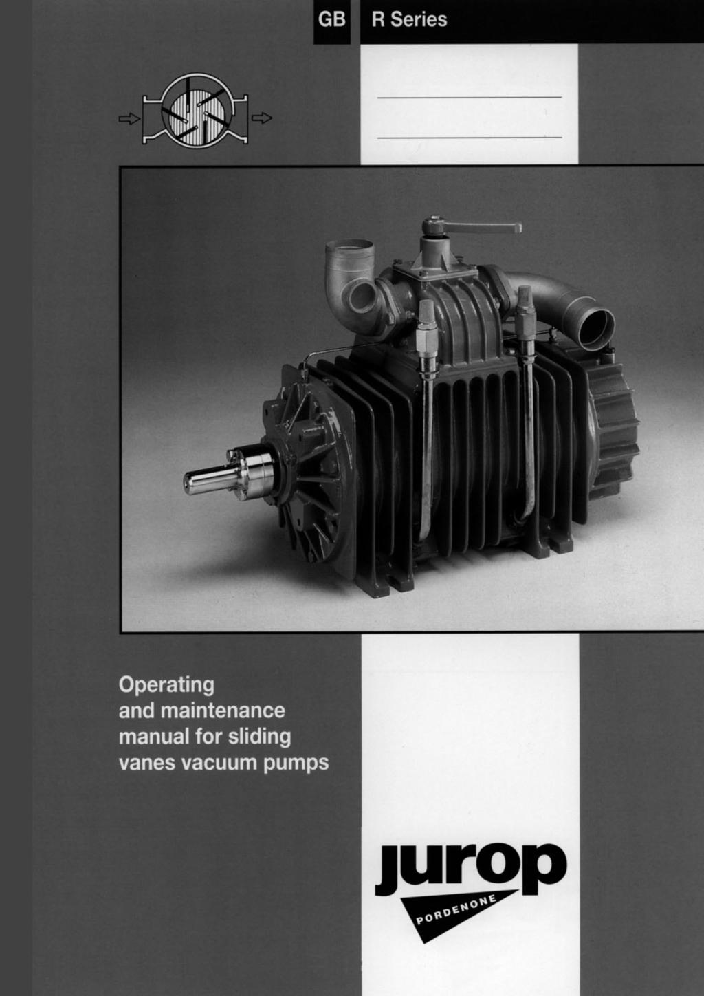
5 2.2 Technical data and performances The JUROP sliding vanes vacuum pumps, R series, cooled by injection of air, are supplied complete with: - High temperature asbestos - free vanes. - Forced lubrication, oil tank. - 4 ways vacuum/pressure changeover valve. - Non-return check valve. - Aluminum inlet/outlet connections. - Splined shaft, smooth shaft or pulley. - "Ballast Port" patented cooling by means of injection of air. Upon request: - Lubrication by means of automatic oil pump. - Electric, hydraulic or auxiliary engine drive. - Righthand (clockwise) or lefthand (counterclockwise) rotation AIR COOLED VACUUM PUMPS SERIES R Performances at 1200 R.P.M. - (max. speed) Model R150 R200 R260 R430 Air flow - l/min. Free air % vacuum Max vacuum - % Max absolute pressure - bar 1,5 1,5 1,5 1,5 Power at 1,5 bar absolute pressure - Kw 8,0 11,5 13,3 20,6 Weight - Kg Oil consumtion g/h-drops/min total 90/50 115/65 135/80 150/95 Oil tank capacity - l. 2,3 2,3 2,3 4 Sound level at 60% vac. 7 m. dist. - db (A) - with silencer LIST OF RECOMMENDED OILS Pump housing lubrication Brand/Type Environment temperature 5 30 C ISO 46 - SAE 20 Environment temperature > 40 C ISO 150 AGIP Diesel sigma 5 Acer 150 B P Venelus C3 Energol CS/50 ESSO Essolube D3 Nuray 150 MOBIL Delvac 1310 Vactra oil extra heavy SHELL Rinula Talpa G150 4
6 2.3 Hydraulic transmission for mod. R HDR A B C Legend 1 Hydraulic motor flange 2 Hydraulic motor 3 Supporting bracket 4 Flexible joint 5 Supporting flange 6 Vaccum pump VACUUM PUMP MOD. R HDR Characteristics of hydraulic motor Dimensions in mm Weight Model cc/rev bar r.p.m. A B C kg R150-HDR 43, R200-HDR 61, R260-HDR 72, R430-HDR 86,
7 3. Safe operating and accident prevention 3.1 General suggestions - Ordinary and extraordinary maintenance has to be done while the unit is stopped and the drive disconnected. - Interventions on pneumatic plants have to be done after disconnecting pressure/vacuum from the same. - Never start the pump if adequate/foreseen safety devices are not installed. Damaged protections must be immediately replaced. - Be aware that during operation the pump s body can reach temperature of over 60 centigrade. Possibility of burnings if this warning is missacted. Maximum speed shown in the technical specifications tables must not be exceeded. 3.2 Normal use - Vacuum pumps of the R-series used for the suction of liquids are foreseen for a max pressure of + 1,5 bar and a max vacuum rate of 92 %. As cooling is given by atmospheric plus forced air, pumps are foreseen for non-continuous duty. Overheating of the pump will cause serious damage of the same and/or blocking of the rotor. In order to the maximum efficiency of the forced air cooling system the filters of the injection valves must be kept clean.(fig. 1) Fig. 1 Filter Valve 6
8 4. Installation 4.1 Checking at arrival - upon receipt check that the pump and related accessories are not damaged. - Check that the rotor/shaft is not blocked. 4.2 Pump mounting / Drive connection - The pump must be installed so that it is easely accessible for inspection and maintenance. - The vacuum pump must be installed on a rigid base or stand. The drive can be by cardan shaft, belts and pulley or by hydraulic motor. - The cardan shaft must be mounted so that it does not create any axial thrust; the inclination of the shaft must not exceed 15 (see fig. 2). - When using the belts and pulley, the pulley can be mounted directly on the rotor shaft eccept for R 430. For model R 430 pumps the pulley must be mounted with the suitable support, supplied by JUROP. The alignment between the pulley of the pump and the driving pulley must be thoroughly checked. The V-belts tension must be normal, that means the belts must flex for about 2 cm. under the thumb pressure. - With the hydraulic transmission the motor must be connected by means of a support and a flexible joint. The transmission must be protected according to current safety standards (for Europe 89/ 392 CEE standards). Check that the actual shaft rotation direction matches that of the arrow on the label fixed on the front of the pump. Fig mm Vacuum pump axle Transmission drive axles must be parallel V-belts must be exactly in line 15 Flange must be perfectly parallel 7
9 4.3 Layout of vacuum line Fig "R" PUMP WITH STANDARD MANIFOLD Legend 1 Primary shutoff 2 Tank 3 Secondary shutoff 4 Silencer + oil trap 5 Vacuum pump "R" 6 Safety relief valve - The mounting of a secondary shutoff (pos. 3) is suggested, inbetween the pump and the tank, for protecting the vacuum pump. - A silencer (pos. 4) is suggested in order to reduce sound level. The application of a safety relief valve and a vacuum relief valve on the tank or along the suction line must be foreseen. 8
10 5. Starting-up instructions 5.1 Oil level checking - Before starting-up the pump, check by the oil dip-stick the level of the oil (fig. 4). If refill is needed only the recommended oils must be used (see page 4) Fig. 4 MAX MIN Oil level check nut for the gear box.5.2 Lubrication checking - When the pump is running, check the correct flow of the oil through the sight glasses of the drip oilers (oil drops must flow regulary). In case of adjustment of oil, the drops must be at least in number of 30 a minute in each drip oiler (oil flow will increase by turning the adjusting pin on the drip oiler counterclockwise and will decrease by turning it clockwise). For oil consumption see page Vacuum / Pressure changeover valve - Rotating the handle of the 4 way valve (pos See following figure) the pump changes over from vacuum to pressure (or viceversa). As the pump can be connected to the vacuum tank with both the front (drive side) connection or the rear (oil tank side) connection in order to avoid mistakes see the following table "Vacuum-Pressure" Manifold Drive Handle pos. Pump function Standard Direct drive Left 1 Pressure Gear box Right 2 Vacuum Direct drive Right 1 Vacuum Gear box Left 2 Pressure Mixer Direct drive Left 1 Vacuum Gear box Right 2 Pressure Direct drive Right 1 Pressure Gear box Left 2 Vacuum 1 2 Connection to the tank - JUROP pumps are normally assembled to be connected to the tank by the front connection (see fig. 3 page 8). - Left hand drive means counterclockwise rotation and Right hand drive means clockwise rotation, looking at the pump from the shaft side. In case the pump is connected to the tank with the rear connection (oil tank side) the functions "Vacuum - Pressure" will be reversed. Be aware not to place the handle in neutral position (half way between the two end positions)otherwise the pump will be by-passed (actually runs idle) 9
11 6. Maintenance 6.1 Ordinary maintenance Fig. 5 a) Re-fill periodically the lubrication oil tank. b) Clean the sight-glasses of the drip-oilers. c) Check that the drive protections are properly fixed. 1 d) On direct-drive models grease the front bearing (pos. 1 - fig.5) e) Clean the filters of the injection valves (ballast ports). 6.2 Extraordinary maintenance Changing of the sliding-vanes: a) Remove the front flange as shown in fig. 5. b) Lubricate the new vanes and insert them after removal of the old ones. c) Replace all the gaskets and seals (ask for the suitable "Gasket kit"). Checking of vanes wear The wear of the vanes can be checked without taking apart the pump. Unscrew the plug (fig. 6) and insert a rod of dia. 6 mm. and turn the shaft by hand. With the checking rod touching the outside diameter of the rotor, mark it a first time with a scriber. Continue turning the shaft till the checking rod falls inside a vane groove touching the vane. Mark the rod a second time. If the distance between the two marks exceeds 5 mm. the vanes must be replaced (see fig. 7). Once finished the checking procedure replace the plug of fig. 6. Fig. 6 - R150 - R200 - R260 Fig. 6 - R430 Vanes wear control plug Vanes wear control plug 10
12 Fig. 7 ø 6 1 st mark 1 Tracciatura 2 nd mark 2 Tracciatura 1 st measure mm Max wear 5 mm Usura max 2 nd measure ø 5 Controllo usura lamelle Checking of vanes wear 1 Misura 2 Misura 6.3 Trouble-shooting Troubles A - Overheating of the pump CAUSE CORRECTION - Faulty lubrication - Check the lubrication - Oil missing - Re-fill the tank - Revs. to high - Reduce revs. - Operation-time too long at too - Stop the pump for a while and let it cool down or high vacuum operate at lower vacuum rate - Clogged filters of "ballast port" - Clean thoroughly the filters injection valves B - Pump consumes too much oil CAUSE CORRECTION - Drip-oiler/s badly adjusted - Adjustment as described - Oiler s pin not sealing - Clean the related seat C - The pump is blocked CAUSE CORRECTION - Broken vanes due to suction of foreign objects or bad - Dismount the pump and replace damaged parts. Check lubrication primary shut-off and lubrication system. - Frozen pump - Unfreeze the vacuum pump - Damaged drive system - Check and replace damaged parts - Flange bolts to tight - Loosen the bolts 11
13 D - Little or no vacuum or pressure in the tank CAUSE CORRECTION - Change-over lever in neutral position - Place lever in right position as shown at point Worn sliding-vanes - Replace the vanes - Loose check-valve - Replace the valve - Worn sealing rings - Replace the rings - Blocked vacuum pump - See previous instructions - Leaking of the gate-valves on the tank - Tighten the valves - Leaking of the seals on the tank - Repair or replace the seals - Primary shut-off blocked - Dismount and clean the parts - Clogged connecting pipeline - Clean the steel pipelines or replace the rubber ones 12
Index. 4. Installation. 1. General advises
 Index 1. General advises 1.1 Introduction pag. 2 1.2 Request of spare parts pag. 2 2. Technical specifications 2.1 Overall dimensions vacuum pumps pag. 3 series R. 2.2 Technical data and performances pag.
Index. 1. General advises 1.1 Introduction pag Request of spare parts Running of the pump pag. 12
 Index 1. General advises 1.1 Introduction pag. 4 1.2 Request of spare parts 4 2. Technical specifications 2.1 Dimensions pag. 4 2.2 Technical data 6 2.3 Performances 6 2.4 Lubrication system 7 3. Safe-operating
KDP VACUUM PUMP HERTELL S. COOP.
 KDP VACUUM PUMP HERTELL S. COOP. Index. Pag. 1.- Introduction 3 1.1.- Previous considerations. 1.2.- General description. 1.3.- Models. 2.- Setting up 5 2.1.- Setting up description. 3.- Pump operation
Operating instructions FPCC FPFG FPCG FPFX FPAC
 Vane pumps Operating instructions FPCC 65 -... FPFG 65 -... Index Page Proper use 2 Type code 2 Technical data 3 Installation 3 Start-up 10 Maintenance 13 Trouble shooting 13 ALFONS HAAR MASCHINENBAU GMBH
Manufacturers of Agricultural Machinery. Hi-Spec Vacuum Tanker
 Manufacturers of Agricultural Machinery Hi-Spec Vacuum Tanker Introduction... 2 Contents... 3 Layout of Vacuum Tankers... 4 Change Over Systems... 5 Pumps... 6 Jurop PN 45/58/84 M... 7 Jurop PN106 M...
TPV Variable Displacement Closed Loop System Axial Piston Pump THE PRODUCTION LINE OF HANSA-TMP HT 16 / M / 851 / 0813 / E
 HYDRAULIC COMPONENTS HYDROSTATIC TRANSMISSIONS GEARBOXES - ACCESSORIES THE PRODUCTION LINE OF HANSA-TMP Variable Displacement Closed Loop System CONTENTS General Information... Order Code... Manual Control
Vacuum Pumps PM80T MORO USA, INC. Use and maintenance manual. ST. LOUIS, MO OFFICE PO Box 632 UNION, MO (866) Fax: (636)
 Fax: (636)") MORO USA, INC. ST. LOUIS, MO OFFICE PO Box 632 UNION, MO 63084 (866) 383-6304 Fax: (636) 583-2044 PITTSBURGH, PA OFFICE SALES OFFICE (800) 383-6304 (412) 415-0421 Fax: (412) 415-3154 Email: sales@morousa.com
MORO USA, INC. ST. LOUIS, MO OFFICE PO Box 632 UNION, MO 63084 (866) 383-6304 Fax: (636) 583-2044 PITTSBURGH, PA OFFICE SALES OFFICE (800) 383-6304 (412) 415-0421 Fax: (412) 415-3154 Email: sales@morousa.com
FPO 80 FPOC FPOS FPON, FPOS Tank truck vane pump
 FPOC 100 -... FPOS 100 -... FPO 80 Tank truck vane pump Operating instructions FPOD, FPOG, FPOJ, Index Page Proper use 2 Type code 3 Technical data 4 Application notes 4 Dimensions 5 Flow charts 9 Input
INSTALLATION, OPERATION AND MAINTENANCE INSTRUCTIONS
 INSTALLATION, OPERATION AND MAINTENANCE INSTRUCTIONS Contents Section 1. General Observations... 2 2. Operation... 4 3. Control During Operation... 5 4. Trouble Shooting... 6 5. Maintenance... 7 Please
Three Lobes Roots Blower. Instruction Manual
 Three Lobes Roots Blower Instruction Manual Welcome to purchase the three lobes roots blower produced by us. You shall read this instruction manual seriously before you use this product in order to ensure
TECHNICAL MANUAL MT029
 Ed.2008 Rev.B REFLUX 919 TECHNICAL MANUAL MT029 INSTALLATION, COMMISSIONING AND MAINTENANCE ISTRUCTIONS TABLE OF CONTENTS Chapter Page 1. AIM 4 2. DESCRIPTION OF THE VALVE 4 3. IDENTIFICATION OF THE VALVE
Single Stage Rotary Vane Vacuum Pump Installation and Operation Manual RX-10 RX-21 RX-25
 V acuum Pumps Single Stage Rotary Vane Vacuum Pump Installation and Operation Manual RX-10 RX-21 RX-25 www.republicsales.com Revised 10.14 2014 Republic Sales & Manufacturing Single Stage Rotary Vane Vacuum
Hey-Wel. 3-lobe Roots Blower OPERATION MANUAL
 Hey-Wel 3-lobe Roots Blower OPERATION MANUAL We would like to thank you at the outset for purchasing the Heywel Roots blower. We have though already done strict inspections on every detail of our blowers
Dry installed pump type LANDY BTP.
 OPERATION & MAINTENANCE MANUAL Dry installed pump type LANDY BTP. Landustrie Sneek BV Pieter Zeemanstraat 6 Tel. 0031 515-486888 P.O. BOX 199 Fax. 0031 515-412398 NL-8600 AD Sneek info@landustrie.nl The
PRODUCT CATALOG BUILT FOR HEAVY-DUTY PERFORMANCE
 PRODUCT CATALOG BUILT FOR HEAVY-DUTY PERFORMANCE MADE IN THE USA 532 CFM Reliable Efficient Cost Effective Exclusive Manufacturer 800-253-5500 887 Vacuum Pump - Page 3 887 Hydraulic Drive Pump - Page 4
ST. LOUIS, MO OFFICE Po Box 632 Union, MO (866) Fax: (636)
 Fax: (636)") MORO USA, INC. MORO USA, INC. ST. LOUIS, MO OFFICE Po Box 632 Union, MO 63084 (866) 383-6304 Fax: (636) 583-2044 PITTSBURGH, PA OFFICE Sales Office (800) 383-6304 (412) 415-0421 Fax: (412) 415-3154 Email:
MORO USA, INC. MORO USA, INC. ST. LOUIS, MO OFFICE Po Box 632 Union, MO 63084 (866) 383-6304 Fax: (636) 583-2044 PITTSBURGH, PA OFFICE Sales Office (800) 383-6304 (412) 415-0421 Fax: (412) 415-3154 Email:
Spere part list PN 45/58/84 D
 Spere part list PN 45/58/84 D Pump showed: PN 84 D CW (ClockWise rotaton) 64 63 13 Spare parts list PN 45/58/84 D PNEUMATIC 4-WAY VALVE PN1 1608557Z7B0 PNEUMATIC ACTUATOR COCK 1 PN2 161258B4B0 PNEUMATIC
Single Stage Rotary Vane Vacuum Pump Installation and Operation Manual RX-40 RX-63 RX-100
 V acuum Pumps Single Stage Rotary Vane Vacuum Pump Installation and Operation Manual RX-40 RX-63 RX-100 www.republicsales.com Revised 02.15 2015 Republic Sales & Manufacturing Single Stage Rotary Vane
Thank you for selecting the GD submersible grinder pump.
 GD INDEX Introduction..PAGE. 2 Nameplate format...page. 2 Prior to Operation...PAGE. 3 Installation....PAGE. 3 Electrical Wiring...PAGE. 4 Operation. PAGE. 5 Maintenance...PAGE. 5 Construction PAGE. 6
SERVICE MANUAL 200 SERIES MOTORIZED 20352, 20452, 20551, 20552, AND MODELS
 Section: MOYNO 500 PUMPS Page:1 of 4 Date: March 1, 1998 SERVICE MANUAL MOYNO 500 PUMPS 200 SERIES MOTORIZED 20352, 20452, 20551, 20552, 22051 AND 22052 MODELS DESIGN FEATURES Housing: AISI 316 stainless
MEC 1000/P MEC 1600/P
 MEC 1000/P MEC 1600/P Owner s Record Date of Purchase: Purchased from: Model: Serial Number: National Vacuum Equipment, Inc. 1999 National Vacuum Equipment, Inc. No part of this manual may be reproduced
INDEX TECHNICAL SPECIFICATIONS 2 SPECIAL TOOLS 3-4 PERIODIC MAINTENANCE 5 LUBRICANTS 6 TROUBLESHOOTING 7-14 TIGHTENING TORQUE TABLE 15
 INDEX TECHNICAL SPECIFICATIONS 2 SPECIAL TOOLS 3-4 PERIODIC MAINTENANCE 5 LUBRICANTS 6 TROUBLESHOOTING 7-14 TIGHTENING TORQUE TABLE 15 ENGINE DISASSEMBLY 16-24 ENGINE REASSEMBLY 25-37 SPECIAL 3-SHOE CLUTCH
AP212 Gear Pumps. Standard and Low Noise series. Reference: 200-P EN-03 1/60. Issue:
 Gear Pumps Standard and Low Noise series Reference: 2-P-99123-EN-3 Issue: 9.215 1/6 Contents Page 1 General information... 4 1.1 External gear pumps components... 5 1.2 Example of typical sound pressure
300 SERIES 30100, 30102, 30104, AND MODELS
 Section: MOYNO 500 PUMPS Page: 1 of 4 Date: March 1, 1998 SERVICE MANUAL MOYNO 500 PUMPS 300 SERIES 30100, 30102, 30104, AND 30105 MODELS DESIGN FEATURES Housing: Phenolic Pump Rotor: Phenolic Elastomers:
GD series Submersible Grinder Pump
 GD series Submersible Grinder Pump 60HZ STAIRS INDUSTRIAL CO., LTD. GD series-submersible Grinder Pump Model code GD - 15-30 - M A A = AUTO M = Single Phase T = Three Phase Connection dimensions Output
Variable Vane Pump, Direct Controlled PV7...A Series 1X / 2X
 Variable Vane Pump, Direct Controlled PV7...A Series 1X / X RE 1 Issue: 1.13 Replaces: 8.8 Sizes 1 to Maximum pressure 1 bar Displacement volume 1 to cm 3 Features Very short control times Low noise Mounting
Maintenance and Service Instruction
 Screw pumps ACD Maintenance and Service Instruction This instruction is valid for all ACD pump models shown on page 2 Contents Page List of components 2 Exploded view/ordering code 3 Service intervals
PVE /117 ED VARIABLE DISPLACEMENT VANE PUMPS WITH DIRECT PRESSURE ADJUSTMENT SERIES 30 OPERATING PRINCIPLE TECHNICAL SPECIFICATIONS
 14 110/117 ED PVE VARIABLE DISPLACEMENT VANE PUMPS WITH DIRECT PRESSURE ADJUSTMENT OPERATING PRINCIPLE The PVE pumps are variable displacement vane pumps with direct pressure regulator. The pump group
TANKERS OPERATING & SAFETY INSTRUCTIONS FOR SPARE PARTS GO TO
 TANKERS OPERATING & SAFETY INSTRUCTIONS FOR SPARE PARTS GO TO WWW.MARSHALL-TRAILERS.CO.UK FOR MODELS: ST1200, ST1400, ST1600, ST1800, ST2000, ST2300, ST2550 CHARLES J. MARSHALL (ABERDEEN) LTD CHAPEL WORKS,
HPD Hydraulic Post Driver
 HPD Hydraulic Post Driver From serial No. 7600 Revised 04.01.2013 Prior to Operation We thank you for choosing a HYCON Post Driver. To ensure smooth operation and long-lasting performance of your new post
AP212HP Cast Iron Gear Pumps
 Cast Iron Gear Pumps Standard and Low Noise series Reference: 200-P-991236-EN-01 Issue: 09.2016 1/56 Contents Page 1 General information... 5 1.1 External gear pumps components... 6 1.2 Technical data...
SERVICING INSTRUCTIONS
 TSP Series 66 Triplex Plunger Pump SERVICING INSTRUCTIONS TRIPLEX TRIPLEX SERVICING PUMP PROCEDURES Valve Replacement: All inlet and discharge valves can be serviced without disrupting the inlet or discharge
ONYX VALVE CO MODEL DAO-PFO Installation & Maintenance
 ONYX VALVE CO MODEL DAO-PFO Installation & Maintenance OPERATION: (4-2010) The Onyx DAO-PFO pinch valve is an open frame valve without housing enclosure and fails open on loss of air. The actuator drives
I & M 8000 Series. Ideal Installation Schematic. Preferred Installation. Trouble Shooting
 I & M 8000 Series 3170 Wasson Road Cincinnati, OH 45209 USA Phone 513-533-5600 Fax 513-871-0105 lowflow@richardsind.com www.lowflowvalve.com Installation & Maintenance Instructions for 8000 Series Low
Troubleshooting the Transmission Hydraulic System
 Testing and Adjusting IT28F INTEGRATED TOOLCARRIER POWER TRAIN Testing And Adjusting Introduction Reference: For Specifications with illustrations, refer to SENR5974, IT28F Integrated Toolcarrier Power
AIR COMPRESSOR OPERATING INSTRUCTION AND PARTS LIST
 AIR COMPRESSOR OPERATING INSTRUCTION AND PARTS LIST BELT TYPE IMPORTANT PLEASE MAKE CERTAIN THAT THE PERSON WHO IS TO USE THIS EQUIPMENT CAREFULLY READS AND UNDERSTANDS THESE INSTRUCTIONS BEFORE STARTING
GLO-502/530 (RIM CLAMP TIRE CHANGER)
") GLO-502/530 (RIM CLAMP TIRE CHANGER) OPERATION MANUAL DATE INSTALLED: SERIAL # MANUFACTURING DATE: (EAGLE - GLOBAL : NHT) TABLE OF CONTENT INTRODUCTION -------------------------------------------------------------------------------2
GLO-502/530 (RIM CLAMP TIRE CHANGER) OPERATION MANUAL DATE INSTALLED: SERIAL # MANUFACTURING DATE: (EAGLE - GLOBAL : NHT) TABLE OF CONTENT INTRODUCTION -------------------------------------------------------------------------------2
Maintenance Information
 04581245 Edition 2 May 2014 Air Grinder, Die Grinder and Sander Series G2 (Angle) Maintenance Information Save These Instructions Product Safety Information WARNING Failure to observe the following warnings,
V Series AXIAL PISTON PUMP ORDER CODE
 V Series AXIAL PISTON PUMP ORDER CODE V A 1 R B S - A D X A 1 Customers demand Pump Series V Links Type (only V -18): none - Standard A - SAE A bolts Ma. (cm 3 /n):, 18, 3,, 38, 4,, 7 Pump Control Type
ONYX VALVE CO MODEL DAO-PFC Installation & Maintenance
 ONYX VALVE CO MODEL DAO-PFC Installation & Maintenance OPERATION: (4-2010) The Onyx DAO-PFC pinch valve is an open frame valve without housing enclosure and fails closed on loss of air. The actuator drives
Flow Control & Pressure Reducing Valve with Hydraulic Control (Sizes 3''- 12"; DN80-DN300)
") IOM IR-472-50-bRU Flow Control & Pressure Reducing Valve with Hydraulic Control (Sizes 3''- 12"; DN80-DN300) Description: The BERMAD Flow Control and Pressure Reducing Valve with Hydraulic Control is a
IOM IR-472-50-bRU Flow Control & Pressure Reducing Valve with Hydraulic Control (Sizes 3''- 12"; DN80-DN300) Description: The BERMAD Flow Control and Pressure Reducing Valve with Hydraulic Control is a
 VOLUME 3.2 2 This page intentionally left blank JTC 760 Operator s Manual PAGE 3 Table of Contents 1 Summary 1.1 Technical Data 4 1.2 Range of Application 4 1.3 Intended Use 5 1.4 Safety Precaution 5 2
Diaphragm Valves Type 15
 Serial No. H-V031-E-8 Diaphragm Valves Type 15 User s Manual Contents (1) Be sure to read the following warranty clauses of our product 1 (2) General operating instructions 2 (3) General instructions for
CHEM-TEX POWER MAX 25 GOLD EDITION TRUCK MOUNT MANUAL
 CHEM-TEX POWER MAX 25 GOLD EDITION TRUCK MOUNT MANUAL Congratulations On your purchase of a Power Max 25 Gold Edition Truck mount. The Power Max 25 Gold Edition are designed for the professional cleaning
HYDRAULICS. TX420 & & lower. Hydraulic Tandem Pump Removal. 4. Remove the LH side panel (Fig. 0388).
.") TX420 & 425 240000299 & lower 4. Remove the LH side panel (Fig. 0388). Hydraulic Tandem Pump Removal Note: Cleanliness is a key factor in a successful repair of any hydraulic system. Thoroughly clean all
TX420 & 425 240000299 & lower 4. Remove the LH side panel (Fig. 0388). Hydraulic Tandem Pump Removal Note: Cleanliness is a key factor in a successful repair of any hydraulic system. Thoroughly clean all
HYDRAULIC PALLET TRUCKS
 HYDRAULIC PALLET TRUCKS HYDRAULIC PALLET TRUCKS MODEL Nos: PT550 GAL & PT685 GAL PART Nos: 7630234 & 7630236 OPERATION & MAINTENANCE INSTRUCTIONS 0204 Please read these instructions carefully before operating
ACHL Series Pump. Operation and Maintenance Manual Air Driven, Hand Operated High Pressure Liquid Pump
 ACHL Series Pump Operation and Maintenance Manual Air Driven, Hand Operated High Pressure Liquid Pump Catalog: 02-9245ME February 2013 Model # Serial # Drawing # Order # Mfg. Date Table of Contents page
HYDRAULIC PUMP. INSTALLATION, OPERATION, & MAINTENANCE MANUAL MAINTENANCE MANUAL #: MM-HP Rev. A Page 1 of 12
 INSTALLATION, OPERATION, & #: MM-HP001 4-20-09 Rev. A Page 1 of 12 HYDRAULIC PUMP PART NUMBER HP46982ALSL & HP46982SL HYDRAULIC PUMP MM-HP001 Rev. A Page 2 of 12 Table of Contents 1.0 General Page 3 2.0
ONYX VALVE CO MODEL DAO-ADA Installation & Maintenance
 ONYX VALVE CO MODEL DAO-ADA Installation & Maintenance OPERATION: (4-2010) The Onyx DAO-ADA pinch valve is an open frame valve without housing enclosure and fails last position on loss of air. This actuator
Ideal Installation. I & M Mark 67 (1/2 6 ) Control Line. Installation & Maintenance Instructions for Mark 67 Pressure Regulators
 Control Line. Installation & Maintenance Instructions for Mark 67 Pressure Regulators") I & M Mark (/ ) 0 Wasson Road Cincinnati, OH 0 USA Phone --00 Fax -8-00 info@richardsind.com www.jordanvalve.com Installation & Maintenance Instructions for Mark Pressure Regulators Warning: Jordan Valve
I & M Mark (/ ) 0 Wasson Road Cincinnati, OH 0 USA Phone --00 Fax -8-00 info@richardsind.com www.jordanvalve.com Installation & Maintenance Instructions for Mark Pressure Regulators Warning: Jordan Valve
Installation and Operating Manual
 Installation and Operating Manual L-Series Vacuum Pumps Models L/H400C - L/H630C INSTALLATION & OPERATING MANUAL L/H-SERIES SINGLE STAGE ROTARY VANE VACUUM PUMPS L/H400C-L/H630C Please read the manual
Maintenance Information
 80234313 Edition 1 June 2006 Air Grinder, Die Grinder, Sander and Belt Sander Series G1 (Angle) Maintenance Information Save These Instructions WARNING Always wear eye protection when operating or performing
PACKING, HANDLING, TRANSPORTING AND STORING MOTORS
 PACKING, HANDLING, TRANSPORTING AND STORING MOTORS Make sure that the shaft of the motor is not loaded in any way and is protected from knocks. Axial loads or shocks may easily damage the bearings inside
Finishing Mower Estate 72
 Finishing Mower Estate 72 Owners/Operators Manual & Spare Parts List Issue Date: October 2011 1 Introduction Your FIELDMASTER Estate 72 Finishing Mower has been designed to do a range of work to your satisfaction.
Athletic Field Painting Pointers Line Star Drawing Line Star Parts List 3-4. Spray Boom Drawing Stainless Steel Tank 6
 TABLE OF CONTENTS TITLE PAGE Athletic Field Painting Pointers 1 44-508 Line Star Drawing 2 44-508 Line Star Parts List 3-4 Spray Boom Drawing 5 40-127 Stainless Steel Tank 6 4085 Spray Gun 7 40-153 Gun
DYNAFLUID 2000 STEAM & WATER MIXING VALVE INSTALLATION & OPERATING MANUAL
 DYNAFLUID 2000 STEAM & WATER MIXING VALVE INSTALLATION & OPERATING MANUAL LILLY ENGINEERING COMPANY 217 CATALPA STREET P.O. BOX 173 ITASCA, ILLINOIS 60143 630-773-2222 FAX: 630-773-3443 www.lillyengineering.com
Eurovacuum Installations and Operating manual EV Series Vacuum pumps Models
 Eurovacuum Installations and Operating manual EV Series Vacuum pumps Models 0010-0630 Single Stage Oil Sealed Rotary Vane Pump Eurovacuum EV Series Single Stage Oil Sealed Rotary Vane Pumps Eurovacuum
Congratulations PRE-OPERATION SETUP
 Congratulations on the purchase of your new ProVac Industrial Pumpout Station. Your new ProVac has been manufactured with the best quality components to give you year after year of trouble free service.
HYDRAULIC PALLET TRUCK. MODEL No: PTE550 PART Nos OPERATION & MAINTENANCE INSTRUCTIONS
 HYDRAULIC PALLET TRUCK MODEL No: PTE550 PART Nos 7630171 OPERATION & MAINTENANCE INSTRUCTIONS 0604 Please read these instructions carefully before operating the truck Thank you for purchasing this CLARKE
GATE VALVES. Type P (Standard: Plug) Type S (Soft Seal) Contents. (1) Be sure to read the following warranty clauses of our product 1
 Type S (Soft Seal) Contents. (1) Be sure to read the following warranty clauses of our product 1") Serial No. H-V011-E-12 GATE VALVES Type P (Standard: Plug) Type S (Soft Seal) Contents (1) Be sure to read the following warranty clauses of our product 1 User s Manual (2) General operating instructions
Serial No. H-V011-E-12 GATE VALVES Type P (Standard: Plug) Type S (Soft Seal) Contents (1) Be sure to read the following warranty clauses of our product 1 User s Manual (2) General operating instructions
TPV Variable Displacement Closed Loop System Axial Piston Pump THE PRODUCTION LINE OF HANSA-TMP HT 16 / M / 852 / 0815 / E
 HYDRAULIC COMPONENTS HYDROSTATIC TRANSMISSIONS GEARBOXES - ACCESSORIES Certified Company ISO 9001-14001 ISO 9001 Via M. L. King, 6-41122 MODENA (ITALY) Tel: +39 059 415 711 Fax: +39 059 415 729 / 059 415
Truck Hydraulics. Serie VP1 Variable Displacement Pumps
 ruck Hydraulics Variable Displacement Pumps aerospace climate control electromechanical filtration fluid & gas handling hydraulics pneumatics process control sealing & shielding Contents Pump and line
Maintenance Manual ASW E Maintenance Manual. Fig Engine Circuit Diagram, part M.Greiner 2.48
 Fig. 2.13.1-2 Engine Circuit Diagram, part 1 TN15 01.07.2016 PA 2.48 Minimum material necessary for re-assembly: Silencer: 4 Schnorr tooth lock washers, S8x13x0,8 Manifold: 4 Thermag-nuts SW12 M8 SSN 441
Instruction Manual & Parts List For H/G323FXFSX-500_ & 800_ Pumps With Flowserve Type BX Cartridge Seal
 TM Instruction Manual & Parts List For H/G323FXFSX-500_ & 800_ Pumps With Flowserve Type BX Cartridge Seal WARNING This Special Instruction Manual and General Instructions Manual, CA-1, should be read
PUMP OWNERS MANUAL CONDE SUPER SERIES PUMPS. Westmoor, Ltd. Performance by Design. Phone: Fax:
 Performance by Design PUMP OWNERS MANUAL CONDE SUPER SERIES PUMPS Westmoor, Ltd. P.O. Box 99, 906 West Hamilton Avenue Sherrill, New York 13461 Phone: 800-367-0972 Fax: 315-363-0193 E-mail pumps@westmoorltd.com
Hydraulic Breakers HH35. Prior to Operation. From Serial No Revised We thank you for choosing a HYCON breaker.
 Hydraulic Breakers HH35 From Serial No. 12263 Revised 01.02.2015 Prior to Operation We thank you for choosing a HYCON breaker. To ensure smooth operation and long-lasting performance of your new breaker,
Vickers 45. VMQ Series 30 Vane Pumps. Fixed Displacement, For Industrial and Mobile Applications (4.188)
") [ (4.188) 49,4 (1.94) /21,8 /.86) 174,7/172,3 (6.88/6.78) 332,9/33,5 (13.11/13.1) "M" is marked if metric port threads No marking if inch port threads AS-568-152 O-ring Vickers 45 65,3 (2.57) 13 (5.1 VMQ
[ (4.188) 49,4 (1.94) /21,8 /.86) 174,7/172,3 (6.88/6.78) 332,9/33,5 (13.11/13.1) "M" is marked if metric port threads No marking if inch port threads AS-568-152 O-ring Vickers 45 65,3 (2.57) 13 (5.1 VMQ
MK Rittenhouse & Sons Ltd. 115 Litre/30 US Gallon Greenhouse Sprayer Manual
 MK Rittenhouse & Sons Ltd. 115 Litre/30 US Gallon Greenhouse Sprayer Manual TABLE OF CONTENTS Introduction 3 Precautions & Maintenance 4-5 Piston pump Care & Maintenance 5-6 Shut Down & Winterizing 6 Troubleshooting
I & M Mark 78 Series. Ideal Installation. Start-Up. Installation & Maintenance Instructions for Mark 78 Control Valves (1-1/2-2 )
") I & M Mark 8 Series 0 Wasson Road Cincinnati, OH 4509 USA Phone 5-5-5600 Fax 5-8-005 info@richardsind.com www.jordanvalve.com Installation & Maintenance Instructions for Mark 8 Control Valves (-/ - ) Warning:
I & M Mark 8 Series 0 Wasson Road Cincinnati, OH 4509 USA Phone 5-5-5600 Fax 5-8-005 info@richardsind.com www.jordanvalve.com Installation & Maintenance Instructions for Mark 8 Control Valves (-/ - ) Warning:
2.- HANDLING OF VALVES BEFORE ASSEMBLY 3.- FITTING THE VALVE TO THE REST OF THE ASSEMBLY 5.- PERIODICAL INSPECTION OF THE VALVE AND MAINTENANCE
 Page 1 of 16 CONTENTS 1.- INTRODUCTION 2.- HANDLING OF VALVES BEFORE ASSEMBLY 3.- FITTING THE VALVE TO THE REST OF THE ASSEMBLY 4.- OPERATION OF A BALL VALVE 5.- PERIODICAL INSPECTION OF THE VALVE AND
Auger Belt Tension Adjustment DB7659
 Rev 1.0 3-23-13 Auger Belt Tension Adjustment DB7659 WARNING Entanglement Hazard - Before performing any adjustment procedures, make sure the engine is off and remove the spark plug wire from the spark
Installation Operation & Maintenance Manual. High Vacuum Lubricated Rotary Vane Pumps
 Installation Operation & Maintenance Manual High Vacuum Lubricated Rotary Vane Pumps Part No. 9983-0000-P07 / November 2018 HIGH VACUUM LUBRICATED ROTARY VANE PUMPS TABLE OF CONTENTS CUSTOMER SERVICE 5
WORKSHOP MANUAL. Chainsaw GS35 GS350 MT350 MT3500
 WORKSHOP MANUAL Chainsaw GS35 GS350 MT350 MT3500 General failures analysis Suggested tools I. Emak tool kit II. Compression tester: to check thermal group III. Electronic tachometer: for 2 and 4 stroke
GMZ series Slurry Pump
 GMZ series Slurry Pump OPERATION MANUAL HL Mud Cleaning Equipment Co.,Ltd Contents 1. Summarizing 2. Structural Drawing 3. Technical Parameters 4. Points for attention for assembly 5. Operation 6. Care
Toothed belt, removing and installing
 Toothed belt, removing and installing Special Tools and Equipment ^ 3212 spanner wrench ^ 3387 pin wrench ^ T40011 pin ^ T40026 locking pin ^ T40028 socket ^ T40030 camshaft adjuster gauge Removing Lock
Catalog HY /NA. Catalog HY /NA. Parker Hannifin Corporation Hydraulic Pump Division Marysville, Ohio USA
 Catalog HY28-6/NA PV, PVT Series Piston Pumps Variable Volume Catalog HY28-6/NA 1 Catalog HY28-6/NA Notes Series PV 2 Catalog HY28-6/NA Introduction Series PV Quick Reference Data Chart Pump Delivery Approx.
INSTALLATION, OPERATION AND MAINTENANCE MANUAL (IOM)
") INSTALLATION, OPERATION AND MAINTENANCE MANUAL (IOM) IOM-1088 03-16 Model 1088 Vacu-Gard Blanketing Valve ISO Registered Company SECTION I I. DESCRIPTION AND SCOPE The Model 1088 Vacu-Gard is a tank blanketing
INSTALLATION, OPERATION AND MAINTENANCE MANUAL (IOM) IOM-1088 03-16 Model 1088 Vacu-Gard Blanketing Valve ISO Registered Company SECTION I I. DESCRIPTION AND SCOPE The Model 1088 Vacu-Gard is a tank blanketing
I & M Mark 78 Series. Ideal Installation. Start-Up. Installation & Maintenance Instructions for Mark 78 Control Valves (1/2-1 )
") I & M Mark 8 Series 30 Wasson Road Cincinnati, OH 4509 USA Phone 53-533-5600 Fax 53-8-005 info@richardsind.com www.jordanvalve.com Installation & Maintenance Instructions for Mark 8 Control Valves (/ -
I & M Mark 8 Series 30 Wasson Road Cincinnati, OH 4509 USA Phone 53-533-5600 Fax 53-8-005 info@richardsind.com www.jordanvalve.com Installation & Maintenance Instructions for Mark 8 Control Valves (/ -
k. Components not properly adjusted. Refer to machine technical manual for proper adjustment of components.
 General Troubleshooting Charts General Troubleshooting Charts Use the charts on the following pages to help in listing all the possible causes of trouble when you begin diagnosing and testing of a machine.
Single Stage Rotary Vane Vacuum Pump Installation and Operation Manual RX-630
 V acuum Pumps Single Stage Rotary Vane Vacuum Pump Installation and Operation Manual RX-630 www.republicsales.com Revised 02.15 2015 Republic Sales & Manufacturing Single Stage Rotary Vane Vacuum Pump
BALTIMATIC 2 ROTOR HAYTEDDER INSTRUCTION & PARTS
 BALTIMATIC 2 ROTOR HAYTEDDER INSTRUCTION & PARTS OWNERS MANUAL/INSTRUCTION AND SPARE PARTS CATALOGUE BALTIMATIC HAY TEDDER 1 INTRODUCTION2 2 APPLICATION OF HAY TEDDER2 3 SAFETY AND WARNINGS 31 general
OPERATING AND MAINTENANCE MANUAL
 Series 2200 Series 2220 Engineered Performance TABLE OF CONTENTS INTRODUCTION 1 About the Series 2200/ 2220 Valve 1 Identifying the valves 1 1.0 VALVE INSTALLATION AND START-UP 2 2 0 VALVE MAINTENANCE
2003 Saturn Vue. SATURN 3.0L V6 DOHC - L-Series After VIN & Vue
 TIMING BELT Removal 1. Disconnect negative battery cable. Remove air cleaner assembly. 2. Raise and support vehicle. Remove right front wheel. Remove lower front splash shield. 3. Lower vehicle. Loosen,
Mounting and operating instructions EB 8093 EN. Series 240 Pneumatic Control Valve for Cryogenic Temperatures. Type and
 Series 240 Pneumatic Control Valve for Cryogenic Temperatures Type 3248-1 and 3248-7 Fig. 1 Type 3248 Cryogenic Valve with Type 3277 Pneumatic Actuator as globe and angle valve Mounting and operating instructions
ELECTRIC ACTUATOR MOD. VB015 MAINTENANCE AND INSTALLATION INSTRUCTIONS OF VALBIA ELECTRIC ACTUATORS
 ELECTRIC ACTUATOR MOD. VB015 MAINTENANCE AND INSTALLATION INSTRUCTIONS OF VALBIA ELECTRIC ACTUATORS TABLE OF CONTENTS 1.0 - WARNINGS 2.0 - GENERAL DATA 2.1 - Technical characteristics 2.2 - Data on electrical
Industrial Turbo Meters, Sizes 2" through 6"
 Industrial Turbo Meters Sizes 2" through 6" TUR-UM-00530-EN-19 (October 2014) User Manual Industrial Turbo Meters, Sizes 2" through 6" User Manual CONTENTS Scope of the Manual 5 Specifications 5 Product
IBT Series Square Drive Torque Wrenches
 IBT Series Square Drive Torque Wrenches Operation and Maintenance Manual Model.75, 1, 3, 5, 8, 10, 20, 25, 35, 50 http://www.torsionx.com Use the IBT Series Square Drive Torque Wrenches Model.75, 1, 3,
TECHNICAL MANUAL GTB16N
 TECHNICAL MANUAL GTB16N 1/20 1. INTRODUCTION 1.1 Purpose 1.2 Before Service 1.3 Safety 1.3.1 Hazard Definitions 1.3.2 For Your Safety 1.4 Specifications & dimensions 1.5 Description 2. HYDRAULIC SYSTEM
This instruction is valid for all ACF/UCF pump models shown on page 2
 Screw pumps A Member of the COLFAX PUMP GROUP ACF/UCF Maintenance and Service Instruction This instruction is valid for all ACF/UCF pump models shown on page 2 Contents Page List of components 2 Exploded
IOM IR-110-X. Solenoid Control Valve
 IOM IR-110-X Solenoid Control Valve (Sizes 1.5''- 6"; DN40-150) Description: The BERMAD Solenoid Controlled Valve is a Hydraulically operated, diaphragm actuated control valve. The BERMAD Model IR-110-X
16K HYDRAULIC PLANETARY CAPSTAN DRIVE
 16K HYDRAULIC PLANETARY CAPSTAN DRIVE CAUTION: READ AND UNDERSTAND THIS MANUAL BEFORE INSTALLATION AND OPERATION OF CAPSTAN DRIVE. SEE WARNINGS! TABLE OF CONTENTS FORWORD...1 WARRANTY INFORMATION...1 SPECIFICATIONS...1
KTM WSM KTM WSM Technical catalogue Catalogo tecnico Technischer Katalog
 KTM WSM KTM 1200-1500 - 1800-2300 WSM 2700-3300 Technical catalogue Catalogo tecnico Technischer Katalog rev. 02 del 18/11/2016 Pneumatic Changeover Attuatore pneumatico Pneumatischer Trieb Suction Unit
SERIES PC INSTRUCTION AND OPERATION MANUAL
 MEGGA SERIES PC INSTRUCTION AND OPERATION MANUAL Models PCT and PCF Close-coupled and frame-mounted single-stage horizontal end-suction pumps. WARNING: Read this manual before installing or operating this
ACTO 400 to MAINTENANCE
 Maintenance 8506.84/2-EN ACTO 400 to 1600 - MAINTENANCE INSTALLATION MAINTENANCE 1- General overview 2- Tooling 3- Installation 4- Draining Procedure and Hydraulic remote control 5- Adjustment of end stops
ZTM AND ZTMB ZENNER TURBINE METERS INSTALLATION, MAINTENANCE AND SERVICING
 ZTM AND ZTMB ZENNER TURBINE METERS INSTALLATION, MAINTENANCE AND SERVICING INSTALLATION 1. The meter is intended for measuring potable, cold water in one direction. 2. The meter is to be installed in a
PNEUMATIC SLIDING VALVE
 INSTALLATION, OPERATION, & #: MM-SV001 6-23-09 Rev. A Page 1 of 8 PNEUMATIC SLIDING VALVE PART NUMBERS (Including, but not inclusive) SV704MSTS, SV714MSTS, SV754MSTS, SV764MSTS, SV774MSTS, SV706MSTS, SV716MSTS,
This instruction is valid for all ACF/UCF pump models shown on page 2
 Screw pumps ACF/UCF Maintenance and Service Instruction This instruction is valid for all ACF/UCF pump models shown on page 2 Contents Page List of components 2 Exploded view/ordering code/ Service intervals
INSTRUCTION MANUAL. Direct Drive Air Compressor 2320, REV A. 1.
 INSTRUCTION MANUAL 2320, REV A Direct Drive Air Compressor CONSTRUCTION DUAL MATERIAL CONSTRUCTION i) The cylinder block is made up of cast iron that prevents wear & tear thus imparting longevity to the
 Operation and Maintenance Manual Model.75,, 3, 5, 8, 0, 0, 5, 35, 50 http://www.torsionx.com Use the MaxDrv Series Square Drive Torque Wrench Model.75,, 3, 5, 8, 0, 0, 5, 35, 50 to install and remove threaded
Troubleshooting 3Z8 038 Rev B
 Troubleshooting 3Z8 038 Rev B INSTRUCTIONS WARNING INJECTION HAZARD This form is only a quick reference for troubleshooting Graco sprayers. To reduce the risk of serious injury, including fluid injection,