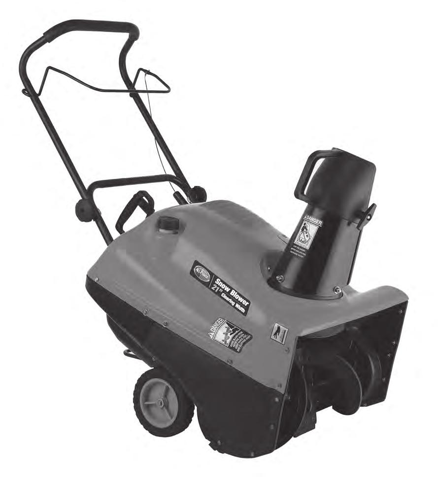
Model: APSB055E Electric Start 196cc Displacement 4 Cycle Engine 21 inch Single Stage Auger Propelled
|
|
|
- Cori Caldwell
- 5 years ago
- Views:
Transcription

1

2 Model: APSB055E Electric Start 196cc Displacement 4 Cycle Engine 21 inch Single Stage Auger Propelled CAUTION: Before using this product,read this manual and follow all of its Safety Rules and Operating Instructions. INTRODUCTION.. 2 RESPONSIBILITY OF THE OWNER...2 RULES FOR SAFE OPERATION. 3 MAINTENANCE AND STORAGE 5 SYMBOLS ASSEMBLY.. 7 OPERATION MAINTENANCE.16 STORAGE TROUBLESHOOTING...20 PARTS.21 1
3 Congratulations on your purchase. This Snowthrower has been designed, engineered and manufactured to give you the best possible dependability and performance. However, like all mechanical products, your machine will occasionally require adjustment and maintenance. This handbook should be read before operating or performing and adjustments on your machine. The instructions in this Owner s Manual are written for a person with some mechanical ability. Like most service books, not all the steps are described. Steps on how to loosen or tighten fasteners are steps anyone can follow with some mechanical ability. Read and follow these instructions before you use the unit. Know your product: If you understand the unit and how the unit operates, you will get the best performance. As you read this manual, compare the illustrations to the unit. Learn the location and the function of the controls. To help prevent an accident, follow the operating instructions and the safety rules. Keep this manual for future reference. IMPORTANT: Many units are not assembled and are sold in cartons. It is the responsibility of the owner to make sure the assembly instructions in this manual are exactly followed. Other units are purchased in an assembled condition. On assembled units, it is the responsibility of the owner to make sure the unit is correctly assembled. The owner must carefully check the unit according to the instructions in this manual before it is first used. The warranty, found in this manual, details the coverage and limitations of this product. It is the responsibility of the owner to follow the instructions below. 1. Carefully read and follow the rules for safe operation. 2. Follow all the assembly instructions. 3. Inspect the unit. 4. Make sure that the operator of the unit knows how to correctly use all standard and accessory equipment. 5. Operate the unit only with guards, shields, and other safety items in place and working correctly. 6. Correctly adjust the unit. 7. Service the unit only with authorized or approved replacement parts. 8. Complete all maintenance on the unit. 2
4 LOOK FOR THIS SYMBOL TO POINT OUT IMPORTANT SAFETY PRECAUTIONS. IT MEANS-- -- ATTENTION!!! BECOME ALERT!!! YOUR SAFETY IS INVOLVED. WARNING: Engine Exhaust, some of its constituents, and certain vehicle components contain or emit chemicals known to the State of California (USA)to cause cancer and birth defects or other reproductive harm. Battery posts, terminals and related accessories contain lead and lead compounds, chemicals known to the State of California(USA)to cause cancer and birth defects or other reproductive harm. WASH HANDS AFTER HANDLING. WARNING: Always disconnect the spark plug wire and place it where it cannot make contact with spark plug to prevent accidental starting during: Preparation, Maintenance, or Storage of your snow thrower. IMPORTANT: Safety standards require operator presence controls to minimize the risk of injury. Your snow thrower is equipped with such controls. Do not attempt to defeat the function of the operator presence control under any circumstances. WARNING: This snow thrower is capable of amputating hands and feet and throwing objects. Failure to observe the following safety instructions could result in serious injury. TRAINING 1. Read this operating and service instruction manual carefully. Be thoroughly familiar with the controls and the proper use of the snow thrower. Know how to stop the snow thrower and disengage the controls quickly. 2. Never allow children to operate the snow thrower. Never allow adults to operate the snow thrower without proper instruction. 3. Keep the area of operation clear of all persons, particularly small children and pets. 4. Exercise caution to avoid slipping or falling especially when operating in reverse. PREPARATION 1. Thoroughly inspect the area where the snow thrower is to be used and remove all doormats, sleds, boards, wires, and other foreign objects. 2. Disengage all clutches before starting the engine (motor). 3. Do not operate the snow thrower without wearing adequate winter outer garments. Wear footwear that will improve footing on slippery surfaces. Avoid loose fitting clothing that can get caught in moving parts. 4. Handle fuel with care; it is highly flammable. a. Use an approved fuel container. b. Never remove fuel tank cap or add fuel to a running engine (motor) or hot engine (motor). 3
5 c. Fill fuel tank outdoors with extreme care. Never fill fuel tank indoors. d. Replace fuel cap securely and wipe up spilled fuel. e. Never store fuel or snow thrower with fuel in the tank inside of a building where fumes may reach an open flame or spark. f. Check fuel supply before each use, allowing space for expansion as the heat of the engine (motor) and/or sun can cause fuel to expand. g. Never fill containers inside a vehicle or on a truck or trailer bed with a plastic liner. Always place containers on the ground, away from vehicle, before filling. h. When practical, remove gas-powered equipment from the truck or trailer and refuel it on the ground. If this is not possible, then refuel such equipment on a trailer with a portable container, rather than from a gasoline dispenser nozzle. i. Keep the nozzle in contact with the rim of the fuel tank container opening at all times, until refueling is complete. Do not use a nozzle lock-open device. j. If fuel is spilled on clothing, change clothing immediately. 5. Let engine (motor) and snow thrower adjust to outdoor temperatures before starting to clear snow. 6. Always wear safety glasses or eye shields during operation or while performing an adjustment or repair to protect eyes from foreign objects that may be thrown from the snow thrower. OPERATION 1. Do not operate this snow thrower if you are taking drugs or other medication which can cause drowsiness or affect your ability to operate this snow thrower. 2. Do not use the snow thrower if you are mentally or physically unable to operate the snow thrower safely. 3. Do not put hands or feet near or under rotating parts. Keep clear of the discharge opening at all times. 4. Exercise extreme caution when operating on or crossing gravel drives, walks or roads. Stay alert for hidden hazards or traffic. 5. After striking a foreign object, stop the engine (motor), remove the wire from the spark plug, thoroughly inspect snow thrower for any damage, and repair the damage before restarting and operating the snow thrower. 6. If the snow thrower should start to vibrate abnormally, stop the engine (motor) and check immediately for the cause. Vibration is generally a warning of trouble. 7. Stop the engine (motor) whenever you leave the operating position, before unclogging the auger/impeller housing or discharge chute and when making any repairs, adjustments, or inspections. 8. When cleaning, repairing, or inspecting, make certain the auger/impeller and all moving parts have stopped and all controls are disengaged. Disconnect the spark plug wire and keep the wire away from the spark plug to prevent accidental starting. 9. Take all possible precautions when leaving the snow thrower unattended. Disengage the auger/ impeller, stop engine (motor), and remove key. 10. Do not start or run engine in enclosed area, even if doors or windows are open. Exhaust fumes are dangerous (containing CARBON MONOXIDE, an ODORLESS and DEADLY GAS). 11. Exercise extreme caution if operating on steep slopping surfaces. 12. Do not clear snow across the face of slopes. Exercise extreme caution when changing direction on slopes. Do not attempt to clear steep slopes. 13. Never operate the snow thrower without proper guards, plates or other safety protective devices in place. 4
6 14. Never operate the snow thrower near enclosures, automobiles, window wells, dropoffs, and the like without proper adjustment of the snow discharge angle. Keep children and pets away. 15. Do not overload the snow thrower capacity by attempting to clear snow at too fast a rate. 16. Never operate the snow thrower at high transport speeds on slippery surfaces. Look behind and use care when backing up. 17. Never direct discharge at bystanders or allow anyone in front of the snow thrower. 18. Disengage power to the collector/impeller when snow thrower is transported or not in use. 19. Use only attachments and accessories approved by the manufacturer of the snow thrower (such as tire chains, electric start kits, ect. ). 20. Never operate the snow thrower without good visibility or light. Always be sure of your footing and keep a firm hold on the handles. Walk; never run. 21. Do not over-reach. Keep proper footing and balance at all times. 22. Do not use the snow thrower on surfaces above ground level such as roofs of residences, garages, porches or other such structures or buildings. 23. This snow thrower is for use on sidewalks, driveways and other ground level surfaces. 24. Never touch a hot engine or muffler. WARNING: This snow thrower is for use on sidewalks, driveways and other ground level surfaces. Caution should be exercised while using on steep sloping surfaces. DO NOT USE SNOW THROWER ON SURFACES ABOVE GROUND LEVEL such as roofs of residences, garages, porches or other such structures or buildings. Clearing A Clogged Discharge Chute WARNING: Hand contact with the rotating impeller inside the discharge chute is the most common cause of injury associated with snow throwers. Never use your hand to clean out the discharge chute. To Clear The Chute:. SHUT OFF THE ENGINE!. Wait 10 seconds to be sure that the impeller blades have stopped rotating.. Always use a clean-out tool, not your hands. 1. Check shear bolts and other bolts at frequent intervals for proper tightness to be sure the snow thrower is in safe working condition. 2. Store the snow thrower away from ignition sources or appliances that have a pilot light, such as hot water and space heaters, clothes dryers, etc... Allow the engine (motor) to cool before storing in any enclosure. 3. Always refer to operator s guide instructions for important details if the snow thrower is to be stored for an extended period. 4. Maintain or replace safety and instruction labels, as necessary. 5. Run the snow thrower a few minutes after throwing snow to prevent freeze-up of the auger/ impeller. 5


7 IMPORTANT: Many of the following symbols are located on your snow thrower or on literature supplied with the product. Before you operate the snow thrower, learn and understand the purpose for each symbol. CONTROL AND OPERATING SYMBOLS Safety Warning Symbols 6


8 WARNING: Always wear safety glasses or eye shieldswhile assembling snow thrower. TOOLS REQUIRED 1 -- Knife to cut carton Figure 1 shows the snow thrower in the operating position. References to the right or left hand side of the snow thrower are from the viewpoint of the operator s position behind the unit. HOW TO REMOVE FROM THE CARTON 1. Locate and remove container of 5W30 oil. 2. Locate all parts packed separately and remove from the carton. 3. Remove and discard the packing material from around the snow thrower. 4. Cut down all four corners of the carton and lay the panels flat. 5. Hold onto the lower handle and pull the snow thrower off the carton. CAUTION: DO NOT back over cables. 6. Remove the packing material from the handle assembly. HOW TO ASSEMBLE THE HANDLE Install Upper Handle 1. Remove the knobs and U bolts from the lower handle (Figure 2). 2. Put the upper handle in the operating position. 3. Install the U--bolts and tighten the knobs. Note: Make sure that the cable is not pinched between the upper and lower handle. Make sure the cable is routed as shown in Figure 2. Figure2 Attach Auger Drive Cable 1. Attach the auger drive cable to the auger drive lever using the Z-hook (Figure 3). 7


9 Adjust The Upper Chute 1. Remove the T--knob and bolt on the upper chute (Figure 4). 2. Rotate the upper chute to the operating position (past the lower chute stop). 3. Install the bolt and tighten the T--knob. Add Engine Oil 1. The snow thrower was shipped with a container of 5W30 engine oil. Before operating, add this oil to the engine. 2. Remove the oil fill cap/dipstick access panel. 3. Remove the oil fill cap/dipstick (Figure 5). Fill to the FULL mark on the oil fill cap/dipstick. Periodically check the oil level. DO NOT OVER FILL. Add Fuel 1. Fill the fuel tank with fresh unleaded fuel. 2. To extend the life of the fuel and prevent starting problems, add the fuel stabilizer supplied with the snowthrower. DO NOT OVER FILL. CHECKLIST Before you operate your new snow thrower, to ensure that you receive the best performance and satisfaction from this quality product, please review the following checklist: 1. All assembly instructions have been completed. 2. The discharge chute rotates freely. 3. No remaining loose parts in carton. While learning how to use your snow thrower, pay extra attention to the following important items: 1. Make sure engine oil is at proper level. Use a high quality detergent oil classified For Service SG, SH, SJ, SL, or higher. 2. Make sure the fuel tank is filled properly with clean, fresh, unleaded gasoline with a minimum of 85 octane. 3. Become familiar with the location of all controls and understand their function. 4. Before starting the engine, make sure all controls operate correctly. 8

10 KNOW YOUR SNOW THROWER READ THIS OWNER S MANUAL AND SAFETY RULES BEFORE OPERATING YOUR SNOW THROWER. Compare the illustrations with your SNOW THROWER to familiarize yourself with the location of various controls and adjustments. Save this manual for future reference. ENGINE AND SNOW THROWER OPERATING CONTROLS The engine operating controls and their functions are as follows: Auger Drive Lever - Starts and stops the auger. Crank Assembly - Changes the direction of snow throwing through the discharge chute. Chute Deflector - Changes the distance the snow is thrown. Discharge Chute - Changes the direction the snow is thrown. Ignition Switch Key - Must be inserted and turned to the ON position to start the engine. Recoil Starter Handle - Starts the engine manually. Electric Starter Button - Use to start the engine when using the 120V electric starter. Choke Control - Used to start a cold engine. Primer Button - Injects fuel directly into the carburetor manifold for fast starts in cold weather. Spark Plug Access Panel - Aides in the removal of the spark plug. Oil Fill Cap/Dipstick Access Panel - Allows access to oil fill cap/dipstick for both filling and checking the engine oil Switch Box - Connection for the electric start power cord. WARNING: Read Owner s Manual before operating machine. Never direct discharge toward bystanders. Stop the engine before unclogging discharge chute or auger housing and before leaving the machine. TO STOP YOUR SNOW THROWER 1. To stop throwing snow, release the auger drive lever. See Figure 6. NOTE: If the snow thrower continues to slowly move forward, see How To Adjust The Auger Control Cable in the Service And Adjustment Section. 2. To stop the engine, move the ignition switch key to the off position (Red Mark). 9
 for more distance, (Down) for less distance. Then tighten the wing knob. (See Figure 7) HOW TO THROW SNOW 1. Engage the auger drive lever. 2.")
11 TO CONTROL SNOW DISCHARGE 1. Turn the chute control rod to set the direction of the snow throwing. 2. Loosen the wing knob on the chute deflector and move the deflector to set the distance. Move the deflector (Up) for more distance, (Down) for less distance. Then tighten the wing knob. (See Figure 7) HOW TO THROW SNOW 1. Engage the auger drive lever. 2. To stop throwing snow, release the auger drive lever. WARNING: The operation of any snow thrower can result in foreign objects being thrown into the eyes, which can result in severe eye damage. Always wear safety glasses or eye shields while operating the snow thrower. We recommend standard safety glasses or use a wide vision safety mask over your glasses. HOW TO MOVE FORWARD 1. Hold the auger drive lever against the handle (See Figure 8). The auger will begin rotating. 2. To go forward, raise the handle to allow the rubber auger blades to contact the ground. Maintain a firm hold on the handle as the snow thrower starts to move forward. Guide the snow thrower by moving the handle either left or right. Do not attempt to push the snow thrower. 3. To stop, release the auger drive lever. NOTE: If the auger continues to rotate, see How To Adjust The Auger Control Cable in the Service and Adjustments section. BEFORE STARTING THE ENGINE 1. Before you service or start the engine, familiarize yourself with the snow thrower. Be sure you understand the function and location of all controls. 2. Be sure that all fasteners are tight. 3. Before starting the engine, make sure all controls operate correctly. To Add Oil NOTE: Engine may already contain some residual oil. Check frequently when filling the crankcase. DO NOT overfill. The snow thrower was shipped with a container of 5W30 motor oil. This oil must be added to the engine before operating. 1. Remove oil fill cap/dipstick access panel. 2. Remove the oil fill cap/dipstick and wipe with a clean cloth. 3. Insert the oil fill cap/dipstick and turn clockwise to tighten. 4. Remove the oil fill cap/dipstick and check the oil. 5. If necessary, add oil until the oil reaches the FULL mark on the oil fill cap/dipstick (see Figure 9). Do not add too much oil. 10

 can attract moisture which leads to separation and formation of acids during storage.")
12 6. Tighten the fill cap/dipstick securely each time you check the oil level. 7. Install the oil fill cap/dipstick access panel. NOTE: Synthetic oil can assist with starting in extreme cold temperatures. Synthetic 5W30 is acceptable for all temperatures. DO NOT mix oil with gasoline. NOTE: Oil level must be at FULL mark. To Add Gas This engine is certified to operate on gasoline. Exhaust Emission Control System: EM (Engine Modifications). WARNING: Alcohol blended fuels (called gasohol or those using ethanol or methanol) can attract moisture which leads to separation and formation of acids during storage. Acidic gas can damage the fuel system of an engine while in storage. NOTE: To avoid engine problems, the fuel system must be emptied before storage for 30 days or longer. Start the engine and let it run until the fuel lines and carburetor are empty. Use fresh fuel next season. See the Storage section in this manual for additional information. Never use engine or carburetor cleaner products in the fuel tank or permanent damage may occur. Fill the fuel tank only with a fresh, clean, unleaded regular, unleaded premium, or reformulated automotive gasoline with a minimum of 85 octane. DO NOT use leaded gasoline. We recommend that you add fuel stabilizer to the gasoline. Use the fuel stabilizer supplied with the unit or purchase Craftsman Fuel Stabilizer No Make sure that the container you pour the gasoline from is clean and free from rust or other foreign particles. Never use gasoline that may be stale from long periods of storage in the container. WARNING: Gasoline is flammable. Always use caution when handling or storing gasoline. 1. Turn engine off and let engine cool at least two minutes before removing the gas cap. 2. Do not fill fuel tank while snow thrower is running, when it is hot, or when snow thrower is in an enclosed area. 3. Keep away from open flame or an electrical spark and do not smoke while filling the fuel tank. 4.Never fill the tank completely. Fill the tank to approximately 1-1/2 below the top of the tank opening to provide space for expansion of fuel. 5. Always fill fuel tank outdoors and use a funnel or spout to prevent spilling. 6. Make sure to wipe up any spilled fuel before stating the engine. 7. Store gasoline in a clean, approved container and keep the cap in place on the container. HOW TO STOP ENGINE CAUTION: To stop the engine, do not move the choke control to CHOKE position. Backfire or engine damage can occur. 1. To stop the engine, push the stop switch to the OFF position, turn the key to the OFF position(red Mark). Figure 10 11

13 TO START ENGINE Be sure that engine oil is at FULL mark on the oil fill cap/dipstick.the snow thrower engine is equipped with a 120 volt A.C.electric starter and recoil starter. Before starting the engine, be certain that you have read the following information. If engine floods, set the choke to the OPEN/RUN position and crank until the engine starts. WARNING: The electric starter is equipped with a three-wire power cord and plug designed to operate on 120 volt AC house hold current. The power cord must be properly grounded at all times to avoid the possibility of electric shock which can cause injury to the operator. Follow all instructions carefully Make sure your house has a three-wire grounded system. If you are not sure, ask a licensed electrician. If your house does not have a three-wire grounded system, do not use this electric starter under any condition. If your house has a three-wire grounded system but a three hole receptacle is not available to connect the electric starter, have a three-hole receptacle installed by a licensed electrician. WARNING: To connect a 120 volt power cord,always connect the power cord first to the switch box located on the engine and then plug the other end into a three-hole grounded receptacle. WARNING: To disconnect the power cord, always unplug the end connected to the threehole grounded receptacle first. How To Start A Cold Engine 1. Be sure auger drive and traction drive levers are in the disengaged (RELEASED) position. 2. Pull the choke knob to the CHOKE position. 3. (Electric Start) Plug the power cord into the starter motor on the engine. Plug the other end of power cord intoa three-hole, grounded 120 VOLT, AC receptacle. 4. Push the primer button as specified below. Remove finger from primer button between pushes. Push two times if temperature is 15 F (-9 C) or higher. Push four times if temperature is below 15 F (-9 C). Primer Button Figure 9 5. (Electric Start) Turn the key to the START position (see Figure 10). To prolong the life of the starter, do not crank for more than 5 seconds at a time. Wait one minute between starts to allow the starter motor to cool. 6. (Recoil Start) Turn the key to the ON position (see Figure 10). Slowly pull the recoil starter handle until resistance is felt and then pull rapidly to start the engine. Do not allow the recoil starter handle to snap back. Slowly return the recoil starter handle. 12
14 WARNING: Rapid retraction of the starter cord (kickback) will pull your hand or arm toward the engine faster than you can let go of the starter cord. This can result in entangled hair or clothing, broken bones, bruises, traumatic amputation or severe lacaration. Do not crank the engine with the spark plug removed.make sure the spark plug, muffler, fuel cap and housing are in place and firmly secured by the equipped fasteners. When starting the engine, slowly pull the starter cord until resistance is felt. Then, rapidly pull the starter cord. Make sure components; such as impellors, pulleys or sprockets, are securely attached. 7. If the engine does not start in 5 or 6 tries, See Difficult Starting in the Troubleshooting Table. Pull starter handle rapidly. Figure Allow the engine to warm up for several minutes. As the engine warms up, adjust the choke knob toward the RUN position. Wait until the engine runs smoothly before each choke adjustment. 9. (Electric Start) First disconnect power cord from receptacle. Then, disconnect the power cord from the starter motor. If after following the preceding instructions, your engine fails to start, have the engine checked by a Service Centre. NOTE: Do not lose the safety/ignition key. Keep the safety/ignition key is a safe place. The engine will not start without the safety/ignition key. How To Start A Warm Engine If restarting a warm engine after a short shutdown, leave the choke lever in the off position and do not push the primer button. If the engine fails to start, follow the Cold Start instructions. WARNING: Never run engine indoors or in enclosed,poorly ventilated areas. Engine exhaust contains CARBON MONOXIDE, AN ODORLESS AND DEADLY GAS. Keep hands, feet, hair and loose clothing away from any moving parts on engine and snow thrower. Engine parts, especially the muffler, become extremely hot. Severe thermal burns can occur on contact. Allow the engine to cool before touching. Never allow children to operate the snow thrower.never allow adults to operate the snow blower without proper instruction. Keep the area of operation clear of all persons, particularly small children and pets. Never leave the snow blower unattended while the engine is running. Anyone operating the engine or equipment must carefully read and understand the operating instructions. IMPORTANT: After each use of the snow blower, stop the engine, remove the safety/ignition key, remove all accumulated snow from the snow blower and wipe clean. Store the snow blower in a protected area. NOTE: Never cover snow blower while engine and exhaust area are still warm. 13
15 Frozen Starter If the starter is frozen and will not turn the engine, follow the steps below. 1. Pull as much starter rope as possible out of the starter. 2. Release the starter handle and let it snap back against the starter. Repeat until the engine starts. Warm engines will cause condensation in cold weather. To prevent possible freeze--up of recoil starter and engine controls, proceed as follows after each snow removal job. 1. With engine off, allow engine to cool for several minutes. 2. Pull starter rope very slowly until resistance is felt, then stop. Allow the starter rope to recoil. Repeat three times. 3. With the engine not running, wipe all snow and moisture from the carburetor cover in area of controls and levers. Also, move the choke control and starter handle several times. WARNING: Never run engine indoors or in enclosed, poorly ventilated areas. Engine exhaust contains CARBON MONOXIDE, AN ODORLESS AND DEADLY GAS. Keep hands, feet, hair and loose clothing away from any moving parts on engine and snow thrower. 1. Engine parts, especially the muffler, become extremely hot. Severe thermal burns can occur on contact. Allow the engine to cool before touching. 2. Never allow children to operate the snow thrower. Never allow adults to operate the snow thrower without proper instruction. 3. Keep the area of operation clear of all persons, particularly small children and pets. 4. Never leave the snowthrower unattended while the engine is running. Anyone operating the engine or equipment must carefully read and understand the operating instructions. HOW TO CLEAR A CLOGGED DISCHARGE CHUTE WARNING: Hand contact with the rotating impeller inside the discharge chute is the most common cause of injury associated with snow throwers. Never use your hand to clean out the discharge chute. To Clear The Chute: 1. SHUT OFF THE ENGINE! 2. Wait 10 seconds to be sure that the impeller blades have stopped rotating. 3. Always use a clean-out tool, not your hands. Use a clean-out tool to remove snow from the auger housing. 1. Release the auger drive lever. 2. Pull out the key. 3. Disconnect spark plug wire. 4. Do not place your hands in the auger or discharge chute. Use a clean-out tool to remove snow or debris. WARNING: Blockage must be cleared only after shutting off the snow thrower and only with a clean-out tool, not by hand. 14
16 SNOW THROWING TIPS 1. When the handle is raised, the auger blades will engage the ground and the snow thrower will move forward. When the auger drive lever is released, the auger blades will stop. 2. Most efficient snow throwing is accomplished when the snow is removed immediately after if falls. 3. Let the engine (motor) and the snow thrower adjust to outdoor temperature before starting to clear snow. 4. For complete snow removal, slightly overlap each previous path. 5. Whenever possible, discharge the snow down wind. 6. The distance the snow will be discharged can be adjusted by moving the discharge chute deflector. Raise the deflector for more distance or lower the deflector for less distance. 7. In windy conditions, lower the chute deflector to direct the discharged snow close to the ground where it is less likely to blow into unwanted areas. 8. For safety and to prevent damage to the snow thrower, keep the area to be cleared free of stones, toys and other foreign objects. 9. When clearing snow from crushed rock or gravel driveways, do not allow the auger blades to contact the driveway. Move the handle down to slightly raise the auger blades. 10. The forward speed of the snow thrower is dependent on the depth and weight of the snow. Experience will establish the most effective method of using the snow thrower under different conditions. 11. After each snow throwing job, allow the engine to run for a few minutes. The snow and accumulated ice will melt off the engine. 12. Clean the snow thrower after each use. 13. Remove ice, snow and debris from the entire snow thrower. Flush with water to remove all salt or other chemicals. Wipe snow thrower dry. DRY AND AVERAGE SNOW 1. Snow up to eight inches deep can be removed rapidly and easily by walking at a moderate rate. For snow or drifts of a greater depth, slow your pace to allow the discharge chute to dispose of the snow as rapidly as the auger receives the snow. 2. Plan to have the snow discharged in the direction the wind is blowing. WET PACKED SNOW Move slowly into wet, packed snow. If the wet, packed snow causes the auger to slow down or the discharge chute begins to clog, back off and begin a series of short back and forth jabs into the snow. These short back and forth jabs, four to six inches, will belch the snow from the chute. SNOW BANKS AND DRIFTS In snow of greater depth than the unit, use the same jabbing technique described above. Turn the discharge chute away from the snow bank. More time will be required to remove snow of this type than level snow. 15


17 CUSTOMER RESPONSIBILITIES GENERAL RECOMMENDATIONS The warranty on this snow thrower does not cover items that have been subjected to operator abuse or negligence. To receive full value from the warranty, the operator must maintain the snow thrower as instructed in this manual. EMISSIONS CONTROL Maintenance, replacement, or repair of the emission control devices and systems can be performed by any non-road engine repair establishment or individual. However to obtain a no--charge emissions control service, the work must be done by a factory authorized dealer. See the Emissions Warranty. WARNING: Do not strike the flywheel with a hammer or a hard object. If done, the flywheel can shatter during operation. Do not tamper with the governor spring, links or other parts to increase engine speed. AFTER EACH USE 1. Run the machine to clear the auger of snow. 2. To prevent freezing of the auger or controls, remove all snow and slush from the snow thrower. 3. Check for any loose or damaged parts. 4. Tighten any loose fasteners. 5. Check and maintain the auger. 6. Check controls to make sure they are functioning properly. 7. If any parts are worn or damaged, replace immediately. LUBRICATION BEFORE STORAGE 16
 65 dba DIMENSION(LXWXH) 312 362 335 DRY WEIGHT 15kg SNOW THROWER ENGINE LUBRICATION Check the crankcase oil level before starting the engine and after each eight (8) hours of")
 hours or at least once a year if the snow thrower is not used for fifty (50) hours. TO CHANGE ENGINE OIL 1.")
18 ENGINE SPECIFICATIONS DISPLACEMENT 196 cc ROTATE SPEED 4000RPM BORE 68mm STROKE 45mm GASOLINE (CAPACITY) 1.5L OIL CAPACITY 0.6L(5W30) SPARK PLUG F7RTC VALVE CLEARANCE Intake: 0.1~0.15 mm Exhaust: 0.15~0.2 mm NOISE( 7m) 65 dba DIMENSION(LXWXH) DRY WEIGHT 15kg SNOW THROWER ENGINE LUBRICATION Check the crankcase oil level before starting the engine and after each eight (8) hours of continuous use. See Figure 16. Add S.A.E. 5W30 motor oil as needed. Synthetic 5W30 is acceptable for all temperatures. Tighten fill cap/dipstick securely each time you check the oil level. Change the oil every fifty (50) hours or at least once a year if the snow thrower is not used for fifty (50) hours. TO CHANGE ENGINE OIL 1. Position the snow thrower so that the oil drain plug is at the lowest point on the engine. 2. When the engine is warm, remove the oil drain plug (see Figure 17) and the oil fill cap/dipstick (see Figure 16). Drain the oil into a suitable container. 3. After draining all the oil, reinstall the oil drain plug securely. 4. Fill the engine crankcase with the recommended motor oil, pouring slowly. DO NOT OVERFILL. See To Add Oil in the Operation Section. Figure 17 TO ADJUST OR REPLACE THE SPARK PLUG Check the spark plug every 25 hours. Replace the spark plug if the electrodes are pitted or burned, if the porcelain is cracked, or every 100 hours of use. The spark plug is housed in the engine compartment under the top cover and cannot be seen under normal conditions. 17

19 1. Open the spark plug access door on the control panel (Figure 18). 2. The spark plug and wire are now visible. 3. Remove the spark plug wire. 4. Clean the area around the spark plug base to prevent dirt from entering the engine when the spark plug is removed. 5. Remove the spark plug. 6. Check the spark plug. If the spark plug is cracked, fouled or dirty, it must be replaced. 7. Set the gap between the electrodes of the new spark plug at inch (Figure 19). 8. Install the spark plug in the cylinder head and firmly tighten. Figure 18 WARNING: To prevent accidental starting when making any adjustments or repairs, always disconnect the spark plug wire and place it where it cannot make contact with the spark plug. ADJUSTAUGERCONTROLCABLE The auger control cable is adjusted at the factory. During normal use, the auger control cable can become stretched and the auger drive lever will not properly engage or disengage the auger. 1. Remove the Z hook from the auger drive lever (Figure 20). 2. Slide the cable boot, if equipped, up the auger control cable until the cable boot does not cover any portion of the cable adjustment bracket (Figure 21). 3. Pull the auger control cable through the eyehole in the cable adjustment bracket as shown by the arrow in Figure 21. This will create enough slack to allow the Z hook to be easily removed. 4. Install the Z hook into the next available adjustment hole in the cable adjustment bracket. This is the adjustment hole located one notch down from where the Z hook was previously attached. 5. Pull the auger control cable back through the eyehole of the cable adjustment bracket until all the slack is taken out of the auger control cable. 6. Slide the cable boot back down over the cable adjustment bracket. 7. Install the Z hook to the auger drive lever (Figure 20). 8. To check the adjustment, start the snow thrower. Make sure the auger does not rotate when the auger drive lever is released. Engage the auger drive lever and make sure auger rotates. If the auger does not rotate, repeat this Adjust Auger Control Cable procedure. 18
20 STORAGE WARNING: Never store your snow thrower with gasoline in the fuel tank indoors or in an enclosed, poorly ventilated area. If gasoline remains in the tank, fumes may reach an open flame, spark or pilot light from a furnace, water heater, clothes dryer, cigarette, etc. To prevent damage (if snow thrower is not used for more than 30 days) follow the steps below. SNOW THROWER 1. Thoroughly clean the snow thrower. 2. Lubricate all lubrication points. See the Maintenance section. 3. Be sure that all nuts, bolts and screws are securely fastened. Inspect all visible moving parts for damage, breakage and wear. Replace if necessary. 4. Touch up all rusted or chipped paint surfaces; sand lightly before painting. 5. Cover the bare metal parts of the blower housing auger and the impeller with rust preventative, such as a spray lubricant. NOTE: A yearly checkup or tune-up by a Sears service center is a good way of ensuring that your snow thrower will provide maximum performance for the next season. ENGINE Gasoline must be removed or treated to prevent gum deposits from forming in the fuel tank, filter, hose, and carburetor during storage. Also, during storage alcohol blended gasoline that uses ethanol or methanol (sometimes called gasohol) attracts water. It acts on the gasoline to form acids which damage the engine. 1. Run the engine until the fuel tank is empty and the engine stops. 2. If you do not remove the gasoline, use fuel stabilizer supplied with unit or purchase Craftsman Fuel Stabilizer No Add fuel stabilizer to any gasoline left in the tank to minimize gum deposits and acids. If the fuel tank is almost empty, mix stabilizer with fresh gasoline in a separate container and add some to the fuel tank. 3. Always follow the instructions on the stabilizer container. After the stabilizer is added to the fuel tank, run the engine at least ten minutes to allow the mixture to reach the carburetor. 4. Change the engine oil. 5. Remove the spark plug and pour about 15 ml (1/2 oz) of engine oil into the cylinder. Replace the spark plug and crank slowly to distribute the oil. 6. Store in a clean and dry area, but NOT near a stove, furnace or water heater which uses a pilot light or any device that can create a spark. OTHER 1. If possible, store your snow thrower indoors and cover it to give protection from dust and dirt. 2. If the snow thrower must be stored outdoors, put the snow thrower on blocks to raise it off of the ground. 3. Cover the snow thrower with a suitable protective cover that does not retain moisture. Do not use plastic. IMPORTANT: Never cover snow thrower while engine and exhaust areas are still warm. 19
21 20
22 Snow Blower LIMITED WARRANTY All-Power warrants to the original purchaser who uses the product in a consumer application (personal, residential or household usage) that all products covered under this warranty are free from defects in material and workmanship for one year from the date of purchase. All products covered by this limited warranty which are used in commercial applications (i.e. income producing) are warranted to be free of defects in material and workmanship for 90 days from the date of original purchase. Products covered under this warranty include air compressors, air tools, service parts, pressure washers and generators. All-Power will repair or replace at All-Power sole option, products or components which have failed within the warranty period. Service will be scheduled according to the normal work flow and business hours at the service center location, and the availability of replacement parts. All decisions of All-Power with regard to this limited warranty shall be final. This warranty gives you specific legal rights, and you may also have other rights which vary from state to state. RESPONSIBILITY OF ORIGINAL PURCHASER (Initial User): To process a warranty claim on this product, DO NOT return item to the retailer. The product must be evaluated by an Authorized Warranty Service Center. For the location of the nearest Authorized Warranty Service Center contact the retailer or place of purchase. Retain original cash register sales receipt as proof of purchase for warranty work. Use reasonable care in the operation and maintenance of the product as described in the Owner s Manual(s). Deliver or ship the product to the nearest Authorized Warranty Service Center. Freight costs, if any, must be paid by the purchaser. Air compressors with 60 and 80 gallon tanks will be inspected at the site of installation. Contact the nearest Authorized Warranty Service Center that provides on-site service calls for service call arrangements. If the purchaser does not receive satisfactory results from the Authorized Warranty Service Center, the purchaser should contact All-Power. 30
23 Owner s Manual LIMITED WARRANTY (cont d) THIS WARRANTY DOES NOT COVER: Merchandise sold as reconditioned, used as rental equipment, or floor or display models. Merchandise that has become damaged or inoperative because of ordinary wear, misuse, cold, heat, rain, excessive humidity, freeze damage, use of improper chemicals, negligence, accident, failure to operate the product in accordance with the instructions provided in the Owner s Manual(s) supplied with the product, improper maintenance, the use of accessories or attachments not recommended by All-Power, or unauthorized repair or alterations. Repair and transportation costs of merchandise determined not to be defective. Costs associated with assembly, required oil, adjustments or other installation and start-up costs. Expendable parts or accessories supplied with the product which are expected to become inoperative or unusable after a reasonable period of use. Merchandise sold by All-Power which has been manufactured by and identified as the product of another company, such as gasoline engines. The product manufacturer's warranty, if any, will apply. ANY INCIDENTAL, INDIRECT OR CONSEQUENTIAL LOSS, DAMAGE, OR EXPENSE THAT MAY RESULT FROM ANY DEFECTS, FAILURE OR MALFUNCTION OF THE PRODUCT IS NOT COVERED BY THIS WARRANTY. Some states do not allow the exclusion, so it may not apply to you. IMPLIED WARRANTIES, INCLUDING THOSE OF MERCHANTABILITY OR FITNESS FOR A PARTICULAR PURPOSE, ARE LIMITED TO ONE YEAR FROM THE DATE OF ORIGINAL PURCHASE. Some states do not allow limitations on how long an implied warranty lasts, so the above limitations may not apply. Distributed by: ALL-POWER AMERICA 31
ST0521M ST0521E Snow Thrower OPERATOR S MANUAL MTF C
 ST0521M ST0521E Snow Thrower OPERATOR S MANUAL INTRODUCTION Congratulations on your purchase of a Frontier Snowthrower. It has been designed, engineered and manufactured to give you the best possible dependability
Introduction. Power Clear 721 Snowthrower Model No Serial No and Up Model No Serial No and Up.
 Power Clear 721 Snowthrower Model No. 38741 Serial No. 402082000 and Up Model No. 38742 Serial No. 402082000 and Up Form No. 3415-621 Rev B Operator's Manual Introduction This machine is intended to be
Safe Operation Practices Set-Up Operation Service Troubleshooting. Snow Thrower. Single-Stage (200 Series)
") Safe Operation Practices Set-Up Operation Service Troubleshooting Operator s Manual Snow Thrower Single-Stage (200 Series) Table of Contents Safe Operation Practices... 2 Assembly & Set-Up... 5 Controls
Safe Operation Practices Set-Up Operation Service Troubleshooting Operator s Manual Snow Thrower Single-Stage (200 Series) Table of Contents Safe Operation Practices... 2 Assembly & Set-Up... 5 Controls
Introduction. Safety. CCR 3650 GTS Snowthrower. Training. Warning. Operator's Manual. CALIFORNIA Proposition 65 Warning
 CCR 3650 GTS Snowthrower Form No. 3353-578 Rev A Model No. 38517 Serial No. 260010001 and Up Operator's Manual Introduction Read this information carefully to learn how to operate and maintain your product
Introduction. Safety. CCR 2450 GTS Snowthrower. Warning. Operator's Manual
 CCR 2450 GTS Snowthrower Form No. 3360-738 Rev A Model No. 38515 Serial No. 290000001 and Up Operator's Manual Introduction Read this information carefully to learn how to operate and maintain your product
OPERATOR S MANUAL SNOWTHROWERS ST1028S ST1130S ST1332S. MT Rev TP LW-T
 OPERATOR S MANUAL SNOWTHROWERS ST1028S ST1130S ST1332S MT1733280 Rev. 04 5-01-07 TP 100-4341-04-LW-T INTRODUCTION Congratulations on your purchase of a Frontier Snowthrower. It has been designed, engineered
42in GT Classic Single Stage Snowthrower Conversion Kit XT Series Garden Tractor
 Form No. 9 66 in GT Classic Single Stage Snowthrower Conversion Kit XT Series Garden Tractor Part No. 06 88 Installation Instructions English (EN) This kit is for installing an existing 00 Series Classic
Water Broom. Instruction manual ESPAÑOL: PÁGINA 7 FRANÇAIS : PAGE 13 MODEL PCA270
 ESPAÑOL: PÁGINA 7 FRANÇAIS : PAGE 13 Instruction manual Water Broom MODEL PCA270 To learn more about Porter-Cable visit our website at: http://www.porter-cable.com IMPORTANT Please make certain that the
Air Compressor. Owner s Manual
 35 WARNING! READ AND UNDERSTAND ALL SAFETY PRECAUTIONS IN THIS MANUAL BEFORE OPERATING. FAILURE TO COMPLY WITH INSTRUCTIONS IN THIS MANUAL COULD RESULT IN PERSONAL INJURY, PROPERTY DAMAGE, AND/ OR VOIDING
42in GT Classic Single Stage Snowthrower Conversion Kit XT Series Garden Tractor
 Form No. 5 70 in GT Classic Single Stage Snowthrower Conversion Kit XT Series Garden Tractor Part No. 06 858 Installation Instructions Original Instructions (EN) This kit is for installing an existing
KING CANADA 950W PORTABLE GENERATOR MODEL: KCG-951G INSTRUCTION MANUAL COPYRIGHT 2011 ALL RIGHTS RESERVED BY KING CANADA TOOLS INC.
 KING CANADA 950W PORTABLE GENERATOR MODEL: KCG-951G INSTRUCTION MANUAL COPYRIGHT 2011 ALL RIGHTS RESERVED BY KING CANADA TOOLS INC. WARRANTY & SERVICE INFORMATION 1-YEAR LIMITED WARRANTY FOR THIS 950W
Operation Manual. 21 Inch Self-Propelled Lawn Mower MODEL #
 21 Inch Self-Propelled Lawn Mower MODEL # 106461 Operation Manual This safety alert symbol identifies important safety messages in this manual. Failure to follow this important safety information may result
ST0726 Snow Thrower OPERATOR S MANUAL MTF L
 ST0726 Snow Thrower OPERATOR S MANUAL INTRODUCTION Congratulations on your purchase of a Frontier Snowthrower. It has been designed, engineered and manufactured to give you the best possible dependability
ST1028 Snow Thrower OPERATOR S MANUAL MTF L
 ST1028 Snow Thrower OPERATOR S MANUAL INTRODUCTION Congratulations on your purchase of a Frontier Snowthrower. It has been designed, engineered and manufactured to give you the best possible dependability
Lawn Mower. 21 Gas Powered. Owner s Manual. Item# PU850 Model# SP-PM137GMC
 Owner s Manual 21 Gas Powered Lawn Mower Item# PU850 Model# SP-PM137GMC WARNING! To Reduce The Risk Of Injury, User Must Read And Understand Instruction Manual. 12/2012 Introduction This rotary-blade,
Operation Manual. 10 Mini-Cultivator MODEL #
 10 Mini-Cultivator MODEL # 103350 Operation Manual This safety alert symbol identifies important safety messages in this manual. Failure to follow this important safety information may result in serious
ST1332 Snow Thrower OPERATOR S MANUAL MTF L
 ST1332 Snow Thrower OPERATOR S MANUAL INTRODUCTION Congratulations on your purchase of a Frontier Snowthrower. It has been designed, engineered and manufactured to give you the best possible dependability
ITEM # V CORDLESS SNOW SHOVEL MODEL #KSS 1280B-06 Español p. 19. ATTACH YOUR RECEIPT HERE Serial Number. Purchase Date
 ITEM #0533632 80 V CORDLESS SNOW SHOVEL MODEL #KSS 1280B-06 Español p. 19 ATTACH YOUR RECEIPT HERE Serial Number Purchase Date Questions, problems, missing parts? Before returning to your retailer, call
Power Clear 621 R Snowthrower. Model No Serial No and Up Model No Serial No and Up Operator's Manual. Model No.
 Power Clear 621 R Snowthrower Form No. 3369-491 Rev B Model No. 38451 Serial No. 312000001 and Up Model No. 38452 Serial No. 312000001 and Up Operator's Manual Introduction This machine is intended to
Instruction Book Model LE389
 16 Instruction Book Model LE389 Read and keep this book for future reference. This book contains important information on SAFETY, ASSEMBLY, OPERATION, AND MAINTENANCE. PRODUCT INFORMATION The owner must
SINGLE STAGE EXTENDED FRAME SNOW THROWER SERIES 0
 Safety Instructions & Operator s Manual for SINGLE STAGE EXTENDED FRAME SNOW THROWER SERIES 0 MODELS SX5200R SX5200E MODEL NUMBER EXPLANATION S X 5 20 0 E MODEL DESIGNATION ENGINE HP ENGINE OPTIONS SERIES
ST0524 Snow Thrower OPERATOR S MANUAL MTF L
 ST0524 Snow Thrower OPERATOR S MANUAL INTRODUCTION Congratulations on your purchase of a Frontier Snowthrower. It has been designed, engineered and manufactured to give you the best possible dependability
OPERATOR / PARTS MANUAL. 12 Amp 20 Electric Snow Thrower 8122
 OPERATOR / PARTS MANUAL Amp 0 Electric Snow Thrower 8 CALIFORNIA Proposition 65 Warning Battery post, terminals, wiring insulation, and related accessories contain lead and lead compounds, chemicals known
ST1028 Snow Thrower OPERATOR S MANUAL MTF L
 ST1028 Snow Thrower OPERATOR S MANUAL INTRODUCTION Congratulations on your purchase of a Frontier Snowthrower. It has been designed, engineered and manufactured to give you the best possible dependability
ITEM # V SNOW SHOVEL. MODEL #KSS 2540A-06 Español p. 18. ATTACH YOUR RECEIPT HERE Serial Number. Purchase Date
 ITEM #0727249 40 V SNOW SHOVEL MODEL #KSS 2540A-06 Español p. 18 ATTACH YOUR RECEIPT HERE Serial Number Purchase Date Questions, problems, missing parts? Before returning to your retailer, call our customer
WARNING! Decals. IMPORTANT INFORMATION Xxxx xxx xxxx xx xxxx x xxxx. Xxxx xxx xxxx xx xxxx x xxxx.
 symbols and decals Xxxx xxx xxxx xx xxxx x xxxx. Used in this publication to notify the reader of a risk of personal injury, particularly if the reader DOES NOT follow the instructions given in the manual.
Single-Stage Snow thrower
 Save This Manual for Future Reference Single-Stage Snow thrower Operator s Manual MODEL NUMBER YB4628 SERIAL NUMBER PURCHASE DATE Both model number and serial number may be found on the main label. You
ST0726 Snow Thrower OPERATOR S MANUAL MTF L
 ST0726 Snow Thrower OPERATOR S MANUAL INTRODUCTION Congratulations on your purchase of a Frontier Snowthrower. It has been designed, engineered and manufactured to give you the best possible dependability
AIR-COOLED DIESEL GENERATOR OWNERʼS MANUAL. This manual contains important safety information. TDG2500E TDGW7000E TDG7000SE TDG4500E
 AIR-COOLED DIESEL GENERATOR OWNERʼS MANUAL This manual contains important safety information. TDG2500E TDGW7000E TDG7000SE TDG4500E TDG8000-3 TDG7000SE-3 TDG7000E TDG8000E TDGW7000SE TDG7000E3 TDGW8000E
LAWN MOWER OWNER S MANUAL
 LAWN MOWER OWNER S MANUAL Woodies SKU: 1153279 & 1153280 CAUTION: Read and follow all Safety Rules and Instructions before operating this equipment Thank you for choosing our Gasoline Lawnmower. 1 To ensure
Read instructions carefully and follow rules for safe operation. Failure to do so could result in serious injury. Fradan Manufacturing Corp.
 OPERATOR MANUAL FRADAN POWER BLOWERS Part No. 888-011-222-0 Read instructions carefully and follow rules for safe operation. Failure to do so could result in serious injury. Fradan Manufacturing Corp.
Earth Auger MAG500 MAG500RS
 Earth Auger MAG500 MAG500RS US Owner s/operator s Manual Completely read and understand this manual before using this product. - 0 - Foreword This Owner s/ Operator s Manual is designed to familiarize
Introduction. Operator's Manual
 Form No. 3373-560 Rev A Power Max Heavy Duty 928 OE and 926/1028 OXE Snowthrower Model No. 38660 Serial No. 313000001 and Up Model No. 38664 Serial No. 313000001 and Up Model No. 38674 Serial No. 313000001
Owner s/operator s Manual
 Water Pump MP2533E2 Owner s/operator s Manual Completely read and understand this manual before using this product. Foreword This Owner s/ Operator s Manual is designed to familiarize the operator with
Model: HT9605H HT0165B. Hurricane Plus OPERATION SERVICE PARTS CARE. Revised 9/04
 Model: HT9605H HT0165B Hurricane Plus OPERATION SERVICE PARTS CARE Revised 9/04 TABLE OF CONTENTS General Safety Instructions 1 & 2 Warning Decal Placement 3 Assembly Instructions 4 Blower Assembly HT
622 Power Throw Snowthrower
 FORM NO. 687 6 Power Throw Snowthrower Model No. 806 990000 & Up Operator s Manual WARNING: The engine exhaust from this product contains chemicals known to the State of California to cause cancer, birth
Parklander Cylinder Mower
 Parklander Cylinder Mower WARNING: To reduce the risk of injury, the user must read and understand the Operator s Manual before using this product. Save these instructions for future reference. Table of
Table of Contents. Safety symbols... 3 Assembly 6. Operation Maintenance Troubleshooting 11. Storage. 12. Notes. 13
 Table of Contents Safety symbols... 3 Assembly 6 Operation... 8 Maintenance... 10 Troubleshooting 11 Storage. 12 Notes. 13 2 Safety Information Attention; this machine can be dangerous! All operators should
824 XL Power Throw Snowthrower
 Form No. 3326-374 Rev A 824 XL Power Throw Snowthrower Model No. 38086 220000001 and Up Operator s Manual Domestic English (EN) Warning The engine exhaust from this product contains chemicals known to
Introduction. Safety. 1028LE Power Max Snowthrower. Warning. Operator s Manual. Form No Rev A. Model No Serial No.
 1028LE Power Max Snowthrower Form No. Introduction Model No. 38642 Serial No. 240000001 and Up Read this manual carefully to learn how to operate and maintain your product properly and to avoid injury
Introduction. Power Max Snowthrowers. Warning. Operator's Manual
 Power Max Snowthrowers Form No. 3362-558 Rev A Model No. 38624 Serial No. 310000001 and Up Model No. 38634 Serial No. 310000001 and Up Model No. 38644 Serial No. 310000001 and Up Model No. 38654 Serial
PF-4000, PF-4010, PF-4210 MULTI-PURPOSE ENGINE
 PF-4000, PF-4010, PF-4210 MULTI-PURPOSE ENGINE Date 09-26-01 Supplier To The Outdoor Power Equipment Industry ISM, Inc. 1028 4 th Street SW Auburn, WA 98001 Phone: (253) 333-1200 Fax: (253) 333-1212 WWW.TANAKA-USA.COM
Electric Snow Thrower
 Electric Snow Thrower model number 060-3999-2 contact us: 1.866.523.5218 IMPORTANT: Read and follow all safety rules and operating instructions before using this product. Operator s Manual 2 Table of Contents
TP300 INDUSTRIAL TRASH PUMP OPERATOR S MANUAL
 TP300 INDUSTRIAL TRASH PUMP OPERATOR S MANUAL IT IS EXTREMELY IMPORTANT TO READ AND UNDERSTAND THE ENTIRE CONTENTS OF THIS OPERATOR S MANUAL BEFORE ATTEMPTING TO OPERATE THE PRODUCT. THIS EQUIPMENT IS
CUB CADET CORP. P.O. BOX CLEVELAND, OHIO
 Operator s Manual Single Stage Snow Thrower Model 421R IMPORTANT: Read safety rules and instructions carefully Warning: This unit is equipped with an internal combustion engine and should not be used on
Trench Filler for Compact Utility Loaders
 Form No. 3353-608 Rev A Trench Filler for Compact Utility Loaders Model No. 22472 260000001 and Up Operator s Manual Register your product at www.toro.com Original Instructions (EN) Contents Page Introduction................................
924, 1028, and 1332 Power Shift Snowthrower
 Form No. 3326-376 Rev A 924, 028, and 332 Power Shift Snowthrower Model No. 38547 22000000 and Up Model No. 38560 22000000 and Up Model No. 38592 22000000 and Up Operator s Manual Domestic English (EN)
MODEL NUMBER EXPLANATION. 11 I a0 I s I " Auger Width 26-26" Auger Width 30-30" Auger Width
 Safety Instructions & Operator's Manual for TWO STAGE LARGE FRAME W THROWER SERIES 5 MODELS 8245 11305 9265 MODEL NUMBER EXPLANATION I 11 I a0 I s I ENGINE HP AUGER WIDTH SERIES DESIGNATION 8-8.0 Engine
824 Power Shift Snowthrower
 Form No. 337-980 84 Power Shift Snowthrower Model No. 38543 3000000 and Up Operator s Manual International English (GB) This spark ignition system complies with Canadian ICES-00. Ce système d allumage
General Power Products
 Portable Electric Generator Owners Manual MODEL: APP 6000 General Power Products IMPORTANT Please make certain the person who uses this Generator thoroughly reads these instructions and all other instructions
Operator s Manual. IMPORTANT: Read safety rules and instructions carefully before operating equipment.
 Operator s Manual Single Stage Snow Thrower Model Series 140 through E173 IMPORTANT: Read safety rules and instructions carefully before operating equipment. Warning: This unit is equipped with an internal
824 XL Power Throw Snowthrower
 Form No. 3327-976 824 XL Power Throw Snowthrower Model No. 38066 230000001 and Up Operator s Manual International English (GB) This spark ignition system complies with Canadian ICES-002. Ce système d allumage
1100W PORTABLE GENERATOR
 1100W PORTABLE GENERATOR MODEL NO: G1200 PART NO: 8010110 OPERATION & MAINTENANCE INSTRUCTIONS LS0312 INTRODUCTION Thank you for purchasing this CLARKE 1100W Portable Generator. Before attempting to use
OWNER S / OPERATOR S MANUAL
 OWNER S / OPERATOR S MANUAL SAFETY PAGE 1 RECOGNIZE SAFETY INFORMATION This is the safety-alert symbol. When you see this symbol in this manual or on your EdgeMasterTM, be alert to the potential for personal
Operator's Manual. WS2690BSE Snow thrower. Safety Setup Instructions Product Overview Controls Operation Maintenance Storage Troubleshooting
 Operator's Manual R WS2690BSE Snow thrower Safety Setup Instructions Product Overview Controls Operation Maintenance Storage Troubleshooting Worldlawn Power Equipment, Inc. Industrial Park 2415 Ashland
Operating and Assembly Manual
 Model 1080 Operating and Assembly Manual Midwest Equipment Manufacturing, Inc. 5225 Serum Plant Road Thorntown, IN 46071 08-02-16 SAFETY RULES Remember, any power equipment can cause injury if operated
8500M INDUSTRIAL GASOLINE GENERATOR OPERATOR S MANUAL
 8500M INDUSTRIAL GASOLINE GENERATOR OPERATOR S MANUAL IT IS EXTREMELY IMPORTANT TO READ AND UNDERSTAND THE ENTIRE CONTENTS OF THIS OPERATOR S MANUAL BEFORE ATTEMPTING TO OPERATE THE PRODUCT. THIS EQUIPMENT
Instruction Model 18537
 Instruction 738-556 Model 18537 LIMITED WARRANTY H. D. Hudson Manufacturing Company warrants to the original purchaser only that this product will continue to function as intended if used in accordance
Wheel Horse. 44 Snowthrower. for 5xi Lawn and Garden Tractors. Model No & Up. Operator s Manual
 FORM NO. 8 Rev A Wheel Horse Snowthrower for 5xi Lawn and Garden Tractors Model No. 7966 890050 & Up Operator s Manual IMPORTANT: Read this manual, and your tractor manual, carefully. They contain information
IMPORTANT INFORMATION
 Table of Contents IMPORTANT INFORMATION Section 1B - Maintenance MAINTENANCE 1 B Specifications................................ 1B-1 Special Tools................................ 1B-2 Quicksilver Lubricant/Sealant..................
Reproduction. Not for OPERATOR S MANUAL ATTACHMENT. 42 Single-Stage Snowthrower. Model No. Description Single Stage Snowthrower
 ATTACHMENT OPERATOR S MANUAL 42 Single-Stage Snowthrower Model No. Description 1695969 42 Single Stage Snowthrower 1751631 Rev: B 2 Table of Contents Table of Contents Hardware... 4 Bag Contents... 4 Box
Introduction. Contents. Power Max Heavy Duty 1128 OXE Snowthrower Model No Serial No and Up WARNING.
 Form No. 3373-565 Rev A Power Max Heavy Duty 1128 OXE Snowthrower Model No. 38680 Serial No. 313000001 and Up Operator's Manual Introduction This machine is intended to be used by residential homeowners
TWO STAGE LARGE FRAME SNOW THROWER SERIES 5
 Safety Instructions & Operator s Manual for TWO STAGE LARGE FRAME SNOW THROWER SERIES 5 8245 9265 MODELS 11305 MODEL NUMBER EXPLANATION 11 30 5 ENGINE HP AUGER WIDTH SERIES DESIGNATION 8 8.0 Engine HP
Make/Type/Size/Model Honda Generator EB 3500X & EB5000X Operators Manual Open Well Ventilated Area to Start & Shut Down Machine
 HONDA GENERATORS ARE DESIGNED TO GIVE SAFE AND DEPENDABLE SERVICE IF OPERATED ACCORDING TO INSTRUCTIONS. YOU CAN HELP PREVENT ACCIDENTS BY BEING FAMILIAR WITH YOUR GENERATORS CONTROLS AND BY OBSERVING
Safe Operation Practices Set-Up Operation Maintenance Service Troubleshooting Warranty. Single-Stage Snow Thrower Model 221 LHP
 Safe Operation Practices Set-Up Operation Maintenance Service Troubleshooting Warranty Operator s Manual Single-Stage Snow Thrower Model 221 LHP WARNING READ AND FOLLOW ALL SAFETY RULES AND INSTRUCTIONS
Power Clear 621 QZR/QZE Snowthrower. Model No Serial No and Up Model No Serial No and Up Operator's Manual
 Form No. Power Clear 621 QZR/QZE Snowthrower 3369-499 Rev B Model No. 38458 Serial No. 312000001 and Up Model No. 38459 Serial No. 312000001 and Up Operator's Manual Introduction This machine is intended
1200W INVERTER GENERATOR
 1200W INVERTER GENERATOR MODEL NO: IG1200 PART NO: 8877070 OPERATION & MAINTENANCE INSTRUCTIONS LS0117 INTRODUCTION Thank you for purchasing this CLARKE 1200W Inverter Generator. Before attempting to use
Water pump Owner's Manual
 Water pump Owner's Manual Safety Precautions I. General Safeguards Please read this operation manual to have a thorough understanding of the content there before use the product. Failure to do so may lead
9000RC INDUSTRIAL GASOLINE GENERATOR OPERATOR S MANUAL
 9000RC INDUSTRIAL GASOLINE GENERATOR OPERATOR S MANUAL IT IS EXTREMELY IMPORTANT TO READ AND UNDERSTAND THE ENTIRE CONTENTS OF THIS OPERATOR S MANUAL BEFORE ATTEMPTING TO OPERATE THE PRODUCT. THIS EQUIPMENT
Decals. IMPORTANT INFORMATION Xxxx xxx xxxx xx xxxx x xxxx. WARNING! Xxxx xxx xxxx xx xxxx x xxxx.
 symbols and decals Xxxx xxx xxxx xx xxxx x xxxx. IMPORTANT INFORMATION Xxxx xxx xxxx xx xxxx x xxxx. Used in this publication to notify the reader of a risk of personal injury, particularly if the reader
North Dakota State University Grounds Maintenance Equipment
 North Dakota State University Grounds Maintenance Equipment I. Introduction Grounds maintenance equipment is an important part of the work activities on NDSU campus. They can make grounds maintenance jobs
TWO STAGE GAS SNOW THROWER
 TWO STAGE GAS SNOW THROWER MODEL DB703-24 and 26 Questions, problems, missing parts? If you have questions or need technical support, call the Amerisun customer service department at -800-79-9458 or visit
Operating and Assembly Manual
 Model 455-IC/PRO/H Operating and Assembly Manual Midwest Equipment Manufacturing, Inc. 5225 Serum Plant Road Thorntown, IN 46071 03-08-12 SAFETY RULES Remember, any power equipment can cause injury if
Introduction. Power Max 824 OE and 826 OXE Snowthrower Model No Serial No and Up Model No Serial No.
 Form No. 3423-315 Rev B Power Max 824 OE and 826 OXE Snowthrower Model No. 37798 Serial No. 400000000 and Up Model No. 37799 Serial No. 400000000 and Up Operator's Manual Introduction This machine is intended
LIMITED WARRANTY. NOTE: All warranty work must be performed by an authorized dealer using original (manufacturer) replacement parts.
 replacement parts.") Model Number 700465-3 Berco Compact Two Stage 40" Snowblower FITS ON LAWN AND YARD TRACTORS WARNING: 107287 - Conditions and Products Covered: BERCOMAC guarantees any part of the product or accessory manufactured
Model Number 700465-3 Berco Compact Two Stage 40" Snowblower FITS ON LAWN AND YARD TRACTORS WARNING: 107287 - Conditions and Products Covered: BERCOMAC guarantees any part of the product or accessory manufactured
Operation Manual. All Terrain Power Cart MODEL #
 All Terrain Power Cart MODEL # 101872 Operation Manual This safety alert symbol identifies important safety messages in this manual. Failure to follow this important safety information may result in serious
IMPORTANT INFORMATION
 Table of Contents IMPORTANT INFORMATION Section 1B - Maintenance MAINTENANCE 1 B Specifications........................... 1B-1 Special Tools........................... 1B-2 Mercury/Quicksilver Lubricants
Sno-Thro. Compact Series. Operator s Manual Manuel du Utilisateur. Models Classic 24 (SN ) Compact 20 (SN )
 Compact 20 (SN )") Operator s Manual Manuel du Utilisateur Compact Series Models 920025 Classic 24 (SN 000101 004999) 920026 Compact 20 (SN 000101 +) 920027 Compact 24 (SN 000101 +) 920028 Compact 24 Track (SN 000101 +)
Operator s Manual Manuel du Utilisateur Compact Series Models 920025 Classic 24 (SN 000101 004999) 920026 Compact 20 (SN 000101 +) 920027 Compact 24 (SN 000101 +) 920028 Compact 24 Track (SN 000101 +)
Introduction. Power Max Heavy Duty 928 OAE Snowthrower Model No Serial No and Up. Operator's Manual
 Form No. 3423-324 Rev A Power Max Heavy Duty 928 OAE Snowthrower Model No. 38840 Serial No. 400000000 and Up Operator's Manual Introduction This machine is intended to be used by residential homeowners.
Operation Manual 21 SNOW BLOWER MODEL #
 21 SNOW BLOWER MODEL # 101487 Operation Manual This safety alert symbol identifies important safety messages in this manual. Failure to follow this important safety information may result in serious injury
Engine Owner s Manual. Models sx4000, i4000, i4500, i5000, i5500, i7000 & i7000xt. Operating & Maintenance Instructions
 Engine Owner s Manual Models sx4000, i4000, i4500, i5000, i5500, i7000 & i7000xt Operating & Maintenance Instructions BEFORE OPERATING ENGINE Read entire Operating & Maintenance Instructions AND the instructions
Operating and Assembly Manual
 Model 470-/H/PRO/IC Operating and Assembly Manual Midwest Equipment Manufacturing, Inc. 5225 Serum Plant Road Thorntown, IN 46071 11-11-11 SAFETY RULES Remember, any power equipment can cause injury if
522, 622, and 724 Snowthrower
 Form No. 3322-80 Rev A 522, 622, and 724 Snowthrower Model No. 3805 20000000 and Up Model No. 38064 20000000 and Up Model No. 38072 20000000 and Up Operator s Manual Pour obtenir gratuitement une version
Operating and Assembly Manual
 Model 455-IC/PRO/H Operating and Assembly Manual Palmor Products Inc. 5225 Serum Plant Road Thorntown, IN 46071 03-08-12 SAFETY RULES Remember, any power equipment can cause injury if operated improperly
LAWN MOWER OWNER S MANUAL
 LAWN MOWER OWNER S MANUAL 1.8kW Petrol Engine 123CC 420mm CUTTING WIDTH MODEL: S421-C SAFETY OPERATION ASSEMBLY MAINTENANCE WARRANTY CAUTION: Read and follow all Safety Rules and Instructions before operating
Model 452-DIC/DH. Operating and Assembly Manual
 . Model 452-DIC/DH Operating and Assembly Manual Palmor Products Inc. 5225 Serum Plant Road Thorntown, IN 46071 02-14-12 SAFETY RULES Remember, any power equipment can cause injury if operated improperly
5.5KVA GENERATOR MODEL NO: PG6500DVES OPERATION & MAINTENANCE INSTRUCTIONS PART NO: LS0616
 5.5KVA GENERATOR MODEL NO: PG6500DVES PART NO: 8857810 OPERATION & MAINTENANCE INSTRUCTIONS LS0616 INTRODUCTION Thank you for purchasing this CLARKE 5.5KVA Generator. Before attempting to use this product,
IMPORTANT! Safety Instructions All Operators Must Read These Instructions Before Use
 Electric Snow Shovel Model No. 324E Form No. SJ324E-880E A Division of Snow Joe, LLC IMPORTANT! Safety Instructions All Operators Must Read These Instructions Before Use Any electrical appliance can be
PORTABLE INVERTER GENERATOR MODEL
 3200Watts PORTABLE INVERTER GENERATOR MODEL #104612 Operation Manual This safety alert symbol identifies important safety messages in this manual. Failure to follow this important safety information may
TWO STAGE GAS SNOW THROWER
 TWO STAGE GAS SNOW THROWER MODEL DB7659-22 and 24 Questions, problems, missing parts? If you have questions or need technical support, call the Amerisun customer service department at 1-800-791-9458 or
AC2T & AC2T-ES INDUSTRIAL GASOLINE AIR COMPRESSOR
 AC2T & AC2T-ES INDUSTRIAL GASOLINE AIR COMPRESSOR INDUSTRIAL GAS AIR COMPRESSOR OPERATOR S MANUAL IT IS ETREMELY IMPORTANT TO READ AND UNDERSTAND THE ENTIRE CONTENTS OF THIS OPERATOR S MANUAL BEFORE ATTEMPTING
3KVA DUAL VOLTAGE GENERATOR MODEL NO: PG3800DV
 3KVA DUAL VOLTAGE GENERATOR MODEL NO: PG3800DV PART NO: 8857815 OPERATION & MAINTENANCE INSTRUCTIONS LS1016 INTRODUCTION Thank you for purchasing this CLARKE 3KVA Dual Voltage Generator. Before attempting
MODEL 565CKG Operating and Assembly Manual Midwest Equipment Manufacturing, Inc Serum Plant Road Thorntown, IN 46071
 MODEL 565CKG Operating and Assembly Manual Midwest Equipment Manufacturing, Inc. 5225 Serum Plant Road Thorntown, IN 46071 11-20-14 SAFETY RULES Remember, any power equipment can cause injury if operated
EC DECLARATION OF CONFORMITY
 EC DECLARATION OF CONFORMITY 14 2500W INVERTER GENERATOR IM2500I CERTIFICATE OF GUARANTEE This product is guaranteed for a period of 1 Year, with effect from the date of purchase and applies only to the
Safety Caution: Improper use may result in loss of fingers, hands, or feet. Before Operating?? Read and understand the contents of this manual before
 Form No. 3358-619 Rev A Power Max 826LE Snowthrower Model No. 38622 Serial No. 270000001 and Up Operator's Manual Introduction Read this information carefully to learn how to operate and maintain your
Operating and Assembly Manual
 Model 380/385-IC/385-LH Operating and Assembly Manual Midwest Equipment Manufacturing, Inc. 5225 Serum Plant Road Thorntown, IN 46071 2-0916 SAFETY RULES Remember, any power equipment can cause injury
Introduction. Contents. Power Clear 621 R/621 E Snowthrower Model No Serial No and Up Model No Serial No.
 Form No. Power Clear 621 R/621 E Snowthrower Model No. 38451 Serial No. 313000001 and Up Model No. 38452 Serial No. 313000001 and Up 3373-698 Rev C Operator's Manual Introduction This machine is intended
824 and 1028 Power Shift Snowthrowers
 FORM NO. 332 378 824 and 028 Power Shift Snowthrowers Model No. 38542 990000 & Up Model No. 38558 990000 & Up Operator s Manual WARNING: The engine exhaust from this product contains chemicals known to
(R86049) WARNING: To reduce the risk of injury, the user must read and understand the operator s manual before using this product.
 WARNING: To reduce the risk of injury, the user must read and understand the operator s manual before using this product.") OPERATOR S MANUAL 12 VOLT LITHIUM-ION BATTERY CHARGER 140446001 (R86049) Your charger has been engineered and manufactured to our high standards for dependability, ease of operation, and operator safety.
OPERATOR S MANUAL 12 VOLT LITHIUM-ION BATTERY CHARGER 140446001 (R86049) Your charger has been engineered and manufactured to our high standards for dependability, ease of operation, and operator safety.
Introduction. Contents. 22in Recycler Lawn Mower with SmartStow Model No Serial No and Up WARNING.
 Form No. 22in Recycler Lawn Mower with SmartStow Model No. 20340 Serial No. 401500000 and Up 3418-793 Rev A Operator's Manual Introduction This rotary-blade, walk-behind lawn mower is intended to be used