TANK, FABRIC, COLLAPSIBLE, FUEL STORAGE
|
|
|
- Berenice Bradford
- 5 years ago
- Views:
Transcription
1 TECHNICAL MANUAL TM &P OPERATOR AND UNIT MAINTENANCE MANUAL (INCLUDING REPAIR PARTS AND SPECIAL TOOLS LIST) TANK, FABRIC, COLLAPSIBLE, FUEL STORAGE 3,000 GALLON, MODEL WTM3KF (EIC = ZVM)/ MIL-T-52983B (EIC = ZC8) (NSN )/(NSN ) 10,000 GALLON, MODEL BA (EIC = ZF3)/BA91-141A (EIC = ZVL) FCE A (EIC = ) (EXTRA ACCESSORIES)/ SC CLE01 (EIC = ZFN) (NSN )/(NSN ) (NSN )/(NSN ) 20,000 GALLON, MODEL BA (EIC = ZF2)/ BA91-140A (EIC = )/BA (EIC = ZFR) (NSN )/(NSN )/ (NSN ) 50,000 GALLON, MODEL PD (EIC = )/M (EIC = ZFB) (NSN )/(NSN ) This manual supersedes TM , dated 31 August 1987, TM , dated 30 November 1978, and TM P, dated 31 August 1988, including all changes. DISTRIBUTION STATEMENT A: Approved for public release; distribution is unlimited HEADQUARTERS, DEPARTMENT OF THE ARMY 28 DECEMBER 2001
2 LIST OF EFFECTIVE PAGES/WORK PACKAGES TM &P DESTROY SUPERSEDED DATA. Original 28 December 2001 Dates of issue for the original manual is: TOTAL NUMBER OF PAGES FOR FRONT AND REAR MATTER IS _24_AND TOTAL NUMBER OF WORK PACKAGES IS 42 CONSISTING OF THE FOLLOWING: Page/WP *Change Page/WP *Change No. No. No. No. Title 0 WP (2 pgs) 0 Warnings 0 WP (4 pgs) 0 i-iv 0 WP (4 pgs) 0 WP (2 pgs) 0 WP (2 pgs) 0 Chap 1 title page 0 WP (2 pgs) 0 WP (8 pgs) 0 WP (2 pgs) 0 WP (2 pgs) 0 WP (2 pgs) 0 Chap 2 title page 0 Chap 6 title page 0 WP (2 pgs) 0 WP (2 pgs) 0 WP (18 pgs) 0 WP (8 pgs) 0 WP (4 pgs) 0 WP (6 pgs) 0 Chap 3 title page 0 WP (40 pgs) 0 WP (8 pgs) 0 WP (2 pgs) 0 WP (8 pgs) 0 WP (4 pgs) 0 Chap 4 title page 0 WP (8 pgs) 0 WP (10 pgs) 0 WP (2 pgs) 0 WP (2 pgs) 0 WP (2 pgs) 0 WP (2 pgs) 0 WP (2 pgs) 0 WP (2 pgs) 0 WP (2 pgs) 0 WP (2 pgs) 0 Glossary 1 thru Glossary 2 0 Chap 5 title page 0 Index 1 thru Index 6 0 WP (2 pgs) 0 WP (2 pgs) 0 WP (2 pgs) 0 WP (8 pgs) 0 WP (2 pgs) 0 WP (6 pgs) 0 WP (6 pgs) 0 WP (2 pgs) 0 WP (2 pgs) 0 WP (4 pgs) 0 WP (4 pgs) 0 *Zero in this column indicates an original page. A/B blank
3
4 TM &P WARNING SUMMARY This warning summary contains general safety warnings and hazardous material warnings that must be understood and applied during operation and maintenance of this equipment. Failure to observe these precautions could result in serious injury or death to personnel. WARNINGS Do not allow smoking within 100 feet (30.50 meters) of the storage area. Death or serious injury may result if personnel fail to observe safety precautions. Avoid spillage of fuel. When spillage occurs, cover the affected area with dry soil to reduce its rate of vaporization. Position fire extinguishers at readily accessible positions around the tank(s). Failure to observe this warning may result in death or serious injury. Avoid getting fuel on the body or clothing. If clothing becomes saturated, remove it immediately and wash the body thoroughly with hot, soapy water. Failure to observe this warning may result in death or serious injury. Safety berms must have capacities of less than one and one-half times that of tank capacities. Failure to construct a secure safety berm may result in death or serious injury. Dry cleaning solvent, A-A-59601, used to clean parts, is potentially dangerous to personnel and property. It produces toxic and flammable fumes. Use only in well-ventilated areas. Avoid repeated and prolonged skin contact. Do not use near an open flame or excessive heat. The flash point of solvent is 100 F to 138 F (38 C to 59 C). Failure to observe these precautions may result in death or serious injury to personnel. Sludge that accumulates in the bottom of the fuel tank gives off toxic and explosive vapors. Inhaling these vapors can cause lead poisoning. When cleaning tanks, provide ample ventilation to carry off harmful fumes. Failure to observe these precautions may result in death or serious injury to personnel. Always wear protective goggles, breathing apparatus, and other protective gear when cleaning the tank interior. Fuel vapors are toxic and can damage eyes, skin, and lungs. Fuel vapors are extremely flammable. Exercise care to prevent sparks when working near or in the tank. Death or severe personal injury can result if safety precautions are not strictly observed. Make certain that the berm gate valve is closed and locked after installation and after draining the berm. In the event of tank rupture, an open berm valve would permit fuel to drain from the berm. Undetected fuel leakage could result in an explosion and cause death, severe personal injury, and damage to equipment. Make sure that the gate valve hand wheel has been rotated fully to the right to the closed position before filling the tank. Undetected draining of the tank could result in an explosion that can cause death or severe personal injury. Be careful when installing a sealing clamp in the tank. Fuel will pour out when a larger slit is made. Leaking fuel can cause personal injury and loss of Government property. a
5 TM &P HEALTH HAZARD The solvent and adhesive furnished in the repair kit are highly flammable and toxic to the skin, eyes, and respiratory tract. Skin/eye protection is required. Avoid prolonged breathing of vapors, and minimize skin contact. Good general ventilation is normally adequate. Keep away from excessive heat, open flame, or other sources of ignition. Clean parts in a well-ventilated area. Avoid inhalation of solvent fumes and prolonged exposure to cleaning solvent. Wash exposed skin thoroughly. Solvent used to clean parts is potentially dangerous to personnel and property. Do not use near open flame or excessive heat. FOR ARTIFICIAL RESPIRATION, REFER TO FM b
6 TM &P HEADQUARTERS DEPARTMENT OF THE ARMY WASHINGTON, D.C., 28 DECEMBER 2001 TECHNICAL MANUAL OPERATOR AND UNIT MAINTENANCE MANUAL (INCLUDING REPAIR PARTS AND SPECIAL TOOLS LIST) TANK, FABRIC, COLLAPSIBLE, FUEL STORAGE 3,000 GALLON, MODEL WTM3KF (EIC = ZVM)/MIL-T-52983B (EIC = ZC8) (NSN )/(NSN ) 10,000 GALLON, MODEL BA (EIC = ZF3)/BA91-141A (EIC = ZVL) FCE A (EIC = ) (EXTRA ACCESSORIES)/SC CLE01 (EIC = ZFN) (NSN )/(NSN )/ (NSN )/(NSN ) 20,000 GALLON, MODEL BA (EIC = ZF2)/BA91-140A (EIC = ZF2)/ BA (EIC = ZFR) (NSN )/(NSN )/ (NSN ) 50,000 GALLON, MODEL PD (EIC = )/M (EIC = ZFB) (NSN )/(NSN ) REPORTING ERRORS AND RECOMMENDING IMPROVEMENTS You can help improve this publication. If you find any mistakes or if you know of a way to improve the procedures, please let us know. Submit your DA Form 2028 (Recommended Changes to Publications and Blank Forms), through the Internet, on the Army Electronic Product Support (AEPS) website. The Internet address is If you need a password, scroll down and click on ACCESS REQUEST FORM. The DA Form 2028 is located in the ONLINE FORMS PROCESSING section of the AEPS. Fill out the form and click on SUBMIT. Using this form on the AEPS will enable us to respond quicker to your comments and better manage the DA Form 2028 program. You may also mail, fax or your letter, or DA Form 2028 direct to: Technical Publication Information Office, TACOM-RI, 1 Rock Island Arsenal, Rock Island, IL The address is TACOM-TECH- PUBS@ria.army.mil. The fax number is DSN or Commercial (309) This manual supersedes TM , dated 31 August 1987, TM , dated 30 November 1978, and TM P, dated 31 August 1988, including all changes. DISTRIBUTION STATEMENT A Approved for public release; distribution is unlimited.
7 TM &P TABLE OF CONTENTS WARNING SUMMARY WP Sequence No. HOW TO USE THIS MANUAL General Information CHAPTER 1 Description and Theory of Operation Equipment Description Principles of Operation CHAPTER 2 Operating Instructions Controls and Indicators Operation Under Usual Conditions Operation Under Unusual Conditions CHAPTER 3 Operator and Unit Troubleshooting Operator Troubleshooting Procedures Unit Troubleshooting Procedures CHAPTER 4 Operator Maintenance Instructions Operator PMCS Procedures Operator Maintenance Procedures Filler/Discharge Valve and Hose Assembly Coupling and Dust Cap Gasket Replacement Vent and Pipe Assembly Coupling and Dust Cap Gasket Replacement Filler/Discharge Assembly Elbow and Dust Cap Gasket Replacement CHAPTER 5 Unit Maintenance Instructions Lubrication Instructions Unit Repair; Tools, Special Tools; Test Measurement and Diagnostic Equipment (TMDE); and Support Equipment Unit Service Upon Receipt Unit PMCS Procedures Unit Maintenance Procedures Filler/Discharge Gate Valve Assembly (Models WTM3KF, MIL-T-52983B, (Models PD , M , BA92-162, FCE A, SC CLE01) Service, Replacement, and Repair Filler/Discharge Butterfly Valve Assembly (Models BA91-141, BA91-140) Service, Replacement, and Repair Filler/Discharge Ball Valve Assembly (Models BA91-141A, BA91-140A) Replacement Filler/Discharge Hose Assembly Service and Replacement Drain Gate Valve (Models WTM3KF, M , BA92-162, FCE A, SC CLE01) Service, Replacement, Repair Drain Ball Valve (Models BA91-141, BA91-140, PD , BA91-141A, BA91-140A) Service, Replacement, Repair Drain Hose Assembly (Except Model MIL-T-52983B) Service Vent and Pipe Assembly Service and Repair Filler/Discharge Assembly Service, Replacement, Repair Drain Fitting Assembly (Except Models MIL-T-52983B, BA91-141, BA91-140) Service and Repair Drain Fitting Assembly (Models BA91-141, BA91-140) Service and Repair Tank Assembly Service ii
8 TM &P Preparation for Storage or Shipment CHAPTER 6 Supporting Information References Maintenance Allocation Chart Repair Parts and Special Tools List Repair Parts List National Stock Number Index Part Number Index Components of End Item (COEI) and Basic Issue Items (BII) Lists Additional Authorization List (AAL) Expendable and Durable Items List Torque Limits Mandatory Replacement Parts List GLOSSARY INDEX ii
9 TM &P HOW TO USE THIS MANUAL Section I. OVERVIEW -This manual is divided into six chapters consisting of 42 work packages that provide all the information necessary to operate and maintain the collapsible fabric fuel tank assemblies. Section II. INDEXING -This manual contains several types of indexes to help the user locate information quickly and efficiently. The different indexes are as follows: a. Table of Contents. Lists all chapters and work packages contained in the manual, along with the work package numbers where they begin. b. Alphabetical Index. Located at the back of the manual, this index lists entries that personnel are most likely to look for. Most listings are provided several times in the index (i.e., "Maintenance Forms and Records" can also be found as "Forms and Records, Maintenance," and "Records, Maintenance Forms and"). This increases the likelihood of finding the information on first entry. Each entry also lists the work package where the information can be found. iii/iv blank
10
11 TM &P OPERATOR AND UNIT MAINTENANCE MANUAL (INCLUDING REPAIR PARTS AND SPECIAL TOOLS LIST) COLLAPSIBLE FABRIC TANKS, FUEL STORAGE, 3,000, 10,000, 20,000, AND 50,000 GALLON GENERAL INFORMATION SCOPE This technical manual contains instructions for operations, checks, and corrective maintenance for 3,000 Gallon (11,360 liter), 10,000 Gallon (37,850 liter), 20,000 Gallon (75,710 liter), and 50,000 Gallon (189,300 liter) Fuel Storage Collapsible Fabric Tanks. Type of Manual: Operator and Unit Maintenance. Model Number and Equipment Names: WTM3KF, MIL-T-52983B, 3000 Gallon Fuel Storage Collapsible Fabric Tanks, BA91-141, BA91-141A, FCE A, SC CLE01, Extra Accessories, 10,000 Gallon Fuel Storage Collapsible Fabric Tank, BA91-140, BA91-140A, BA92-162, 20,000 Gallon Fuel Storage Collapsible Fabric Tank, PD , M , 50,000 Gallon Fuel Storage Collapsible Fabric Tank. Purpose of Equipment: The tanks are containers designed to store a variety of petroleum liquids. The tanks will be used to store fuel as part of a bulk fuel terminal. Fuel will be available for use in a quick response deployment operation. The tanks are made of tough polymer-coated nylon fabric, and care must be taken not to puncture or tear the material. DRAIN HOSE ASSEMBLY VENT AND PIPE ASSEMBLY FILLER/DISCHARGE ASSEMBLY FILLER AND DISCHARGE VALVE ASSEMBLY FILLER AND DISCHARGE HOSE ASSEMBLY TANK
12 TM &P MAINTENANCE FORMS, RECORDS AND REPORTS Department of the Army forms and procedures used for equipment maintenance will be those prescribed by (as applicable) DA Form 2404, Equipment Inspection and Maintenance Worksheet, DA Form 2407, Maintenance Request, DA Form Maintenance Request Continuation Sheet, DA PAM , The Army Maintenance Management System DA PAM , Functional Users Manual for The Army Maintenance Management System Aviation (TAMMS-A) or AR , Army Logistics Readiness and Sustainability. CORROSION PREVENTION AND CONTROL (CPC) Corrosion prevention and control of Army materiel is a continuing concern. It is important that any corrosion problems with this item be reported so that the problem can be corrected and improvements can be made to prevent the problem in future items. While corrosion is typically associated with rusting of metals, it can also include deterioration of other materials, such as rubber and plastic. Any unusual cracking, softening, swelling, or breaking of the materials may be a corrosion problem. If a corrosion problem is identified, it can be reported using Standard Form 368, Product Quality Deficiency Report. Use of key words such as "rust," "deterioration," "corrosion," or "cracking" will ensure that the information is identified as a CPC problem. The form should be submitted to the address specified in DA Pam DESTRUCTION OF ARMY MATERIEL TO PREVENT ENEMY USE Command decisions, according to tactical situations, will determine when destruction of the collapsible fabric fuel tank assembly will be accomplished. A destruction plan will be prepared by the using organization, unless higher authority has prepared one. For general destruction procedures for this equipment, refer to TM , Procedures for Destruction of Equipment to Prevent Enemy Use. REPORTING EQUIPMENT IMPROVEMENT RECOMMENDATIONS (EIR's) If the collapsible fabric fuel tank assemblies need improvement, notify publications by sending an EIR. The tank user is the only personnel that can report dissatisfaction with the equipment. Report discrepancies in the design or performance of the equipment. Fill out an SF 368 (Product Quality Deficiency Report), and mail it to: Commander, U.S. Army Tank-automotive and Armaments Command, AMSTA-LC-CIP-WT, Rock Island, IL PREPARATION FOR STORAGE OR SHIPMENT Army users refer to work package QUALITY ASSURANCE/QUALITY CONTROL (QA/QC) Workmanship shall be of the highest quality and shall permit no defects not repaired in accordance with the instructions in this manual. All metal parts shall be clean and free of sand, dirt, etc. The inside and outside of the tank shall be clean and free of foreign material. END OF WORK PACKAGE
13 TM &P CHAPTER 1 DESCRIPTION AND THEORY OF OPERATION TANK, FUEL STORAGE, 3,000 GALLON, 10,000 GALLON 20,000 GALLON, AND 50,000 GALLON
14 TM &P OPERATOR AND UNIT MAINTENANCE MANUAL (INCLUDING REPAIR PARTS AND SPECIAL TOOLS LIST) COLLAPSIBLE FABRIC TANKS, FUEL STORAGE, 3,000, 10,000, 20,000, AND 50,000 GALLON EQUIPMENT DESCRIPTION EQUIPMENT CHARACTERISTICS, CAPABILITIES, AND FEATURES Characteristics, capabilities, and features of the collapsible fabric fuel tank assemblies include: a. Constructed of tough polymer-coated nylon fabric with triple-wall thickness protection. b. Vulcanized handles for easy tank positioning. c. Various assemblies attach to hoses and related hardware with quick-disconnects. d. The filled tank expands vertically and internal pressure is vented. 3,000-Gallon Collapsible Fabric Fuel Storage Tank The 3,000-Gallon (11,360-liter) fuel tank is used for the storage of petroleum-based fuels. The unit consists of a collapsible fabric fuel tank with one filler/discharge assembly, elbow fitting, a vent fitting assembly with relief valve, a 4.0-foot (1.219 meter) filler/discharge hose assembly with control valve, a 4.0-inch (10.16 centimeters) female to 3.0-inch (7.62 centimeters) male reducer, and emergency repair items. RELIEF VALVE IDENTIFICATION PLATE TANK DUST CAP VENT ASSEMBLY HOSE ASSEMBLY HANDLE INFORMATION PLATE REDUCER FILLER/DISCHARGE ASSEMBLY WITH ELBOW FILLER/DISCHARGE CONTROL VALVE
15 TM &P ,000-Gallon Collapsible Fabric Fuel Storage Tank NOTE When the basic fuel tank, issued under SC CLE01, NSN , becomes unserviceable, replacement requisitions should be submitted for fuel tank NSN The accessory items issued with NSN should be retained and should not be turned in when only the collapsible fabric tank itself is unserviceable. These accessories should be retained for use with the replacement tank (NSN ), as this tank is not issued with all the accessories that come with the tank assembly issued under SC CLE01. Replacement tanks will be issued in wooden crates only. The aluminum chest may be requisitioned at unit level for storage, as desired. NSN , 10,000-Gallon (37,850-liter) tank is used for the storage of petroleum-based fuels. The unit consists of a collapsible tank with one filler/discharge assembly with elbow, a vent fitting assembly with relief valve, eight 10.0-foot (3.05 meter) filler/discharge hose assemblies, numerous adapters, coupling-halves, dust caps and plugs, reducers, manifolds, an aluminum storage chest or wooden box, and emergency repair items. NSN , 10,000-Gallon (37,850-liter) tank is used for the storage of petroleum-based fuels. The unit consists of a collapsible fabric fuel tank with one filler/discharge assembly, elbow fitting, a vent fitting assembly with relief valve, a drain fitting assembly with a 6.0-foot (1.82 meter) drain hose with control valve, an aluminum storage chest (or crate), and emergency storage items. IDENTIFICATION PLATE RELIEF VALVE DRAIN FITTING IDENTIFICATION PLATE VALVE ASSEMBLY TANK DRAIN HOSE DUST CAP HANDLE DRAIN CONTROL VALVE INFORMATION PLATE FILLER/DISCHARGE ASSEMBLY WITH ELBOW
16 TM &P ,000-Gallon Collapsible Fabric Fuel Storage Tank The 20,000-Gallon (75,710-liter) fuel tank is used for the storage of petroleum-based fuels. The unit consists of a collapsible fabric fuel tank with two filler/discharge assemblies with elbow fittings, a vent fitting assembly with relief valve, a drain fitting assembly with an 8.0-foot (2.44 meter) drain hose with gate valve, two 10.0-foot (3.05 meter) filler/discharge hose assemblies with a gate valve, and emergency repair items. FILLER/DISCHARGE ASSEMBLY AND ELBOW FITTING CAUTION LABEL IDENTIFICATION LABEL VENT FITTING VALVE TANK DRAIN FITTING DUST CAP DRAIN HOSE HANDLE, (TYPICAL 12 LOCATIONS) DRAIN GATE VALVE FILLER/DISCHARGE GATE VALVE FILLER/DISCHARGE ASSEMBLY AND ELBOW FITTING FILLER/DISCHARGE HOSE
17 TM &P ,000-Gallon Collapsible Fabric Fuel Storage Tank The 50,000-Gallon (189,300-liter) fuel tank is used for the storage of petroleum-based fuels. The unit consists of a collapsible fabric fuel tank with two filler/discharge assemblies with elbow fittings, a vent fitting assembly with relief valve, a drain fitting assembly with an 8.0-foot (2.44 meter) drain hose with control valve, an 8.0-foot (2.44 meter) filler/discharge hose assembly with control valve and emergency repair items. FILLER/DISCHARGE ASSEMBLY INFORMATION PLATE TANK FILLER/DISCHARGE ASSEMBLY WITH ELBOW RELIEF VALVE IDENTIFICATION PLATE INFORMATION PLATE DRAIN FITTING VENT ASSEMBLY HANDLE DUST CAP INFORMATION PLATE FILLER/DISCHARGE HOSE DRAIN CONTROL VALVE FILLER/DISCHARGE CONTROL VALVE
18 LOCATION AND DESCRIPTION OF MAJOR COMPONENTS See WP DECAL MARKINGS TM &P Identification Plate. The tanks are fitted with a bonded identification label, which lists the following: Description: Federal or NSN: Serial number: Manufacturer s name and plant location: Date of manufacture, weight (empty), contract number: Information Plate. The following information shall be located adjacent to each fitting assembly: Maximum Torque inch pounds. Caution Label. NSN The following information shall be located adjacent to each fitting assembly: CAUTION Overfilling will result in permanent damage and failure of the tank. DO NOT OVERFILL Maximum Capacity When Full...20,000-Gallon (75,710 liter) Maximum Tank Height When Full ft (1.7 meters) EQUIPMENT DATA 3,000 - GALLON TANK Temperature Range (Desired-5 Years Maximum) Low F ( C) High F ( C) Dimensions, Outside (Packaged) Height inches (73.15 cm) Width inches (71.12 cm) Length ft. 5.0 inches (1.651 m) Crated Weight pounds ( kg) Dry Weight pounds (61.23 kg) Dimensions (Filled) Height (Depth) feet (1.219 m) Width feet (3.840 m) Length feet (3.840 m) Dimensions (Dry) Width feet (3.962 m) Length feet m) Fuel Storage Capacity... 3,000 gallons ( liters)
19 TM &P ,000 - GALLON TANK Temperature Range (Desired-5 Years Maximum) Low F (-3.67 C) High F ( C) Dimensions, Outside (Empty) Width feet (6.70 m) Length feet (6.70 m) Dry Weight pounds (81.65 kg) Crated Weight pounds ( kg) Dimensions (Filled) Height (Depth) feet (1.219 m) Width feet (3.840 m) Length feet (3.840 m) Dimensions (Dry) Width feet (6.70 m) Length feet (6.70 m) Crate Dimensions Height (Depth) inches (68.58 cm) Width inches (76.20 cm) Length ft.7.0 inches (4.140 m) Fuel Storage Capacity... 10,000-gallons (37,850 liters) 20,000 - GALLON TANK Temperature Range (Desired-5 Years Maximum) Low F (-3.67 C) High F ( C) Dimensions, Outside (Packaged) Height (Depth) feet (0.85 m) Width feet (.948 m) Length feet (1.04 m) Dimensions (Filled) Height (Depth) feet (1.71 m) Width feet (7.35 m) Length feet (8.26 m) Dimensions (Dry) Width feet (7.31 m) Length feet (8.53 m) Dry Weight pounds ( kg) Crated Weight pounds ( kg) Fuel Storage Capacity... 20,000 gallons (75,710 liters) 50,000 - GALLON TANK Temperature Range (Desired -5 Years Maximum) Low F (-3.67 C) High F ( C) Dimensions, Outside (Packaged) Height (Depth) feet (1.07 m) Width feet (1.01 m) Length feet (3.66 m) Dimensions (Filled) Height (Depth) feet (1.768 m) Width feet (7.315 m) Length feet (19.51 m)
20 TM &P Dimensions (Dry) Width feet (7.925 m) Length feet (20.12 m) Dry Weight pounds ( kg) Crated Weight pounds ( kg) Fuel Storage Capacity... 50,000 gallons (189,300 liters) END OF WORK PACKAGE /8 blank
21
22 PRINCIPLES OF OPERATION TM &P OPERATOR AND UNIT MAINTENANCE MANUAL (INCLUDING REPAIR PARTS AND SPECIAL TOOLS LIST) COLLAPSIBLE FABRIC TANKS, FUEL STORAGE, 3,000, 10,000, 20,000, AND 50,000 GALLON PRINCIPLES OF OPERATION Connecting a hose from a fuel truck or other fuel source to the filler/discharge hose assembly fills the collapsible fuel tank. This assembly is connected, in turn, to the gate, ball, or butterfly valve that has been connected to the filler/discharge assembly. Gate, ball, or butterfly valves are used to control the flow of the fuel. Connecting the filler/discharge hose assembly, and gate, ball, or butterfly valve to the filler/discharge assembly discharges the collapsible fuel tank. Water, sludge, and residual fuel are drained through the drain hose assembly at the bottom of the tank. The fuels are extremely hazardous, and all safety procedures must be strictly followed. The vent and pipe assembly contains a relief cap that opens automatically when the tank vapor reaches an internal pressure of 0.10 psi ( atmospheres). END OF WORK PACKAGE /2 blank
23
24 TM &P CHAPTER 2 OPERATING INSTRUCTIONS TANK, FUEL STORAGE, 3,000 GALLON, 10,000 GALLON 20,000 GALLON, AND 50,000 GALLON
25 TM &P OPERATOR AND UNIT MAINTENANCE MANUAL (INCLUDING REPAIR PARTS AND SPECIAL TOOLS LIST) COLLAPSIBLE FABRIC TANKS, FUEL STORAGE, 3,000, 10,000, 20,000, AND 50,000 GALLON CONTROLS AND INDICATORS GENERAL This section lists major components, controls, and indicators, and describes the functions within the collapsible fabric, fuel storage tank assemblies. DESCRIPTION AND USE OF MAJOR COMPONENTS Description and use of major components, including controls and indicators, are contained in Table Table 1. Major Components, Controls and Indicators Key Component, Control, or Indicator 1 Filler/Discharge Gate Valve (Models MIL-T-52983B, WTM3KF, FCE A, SC CLE01, BA92-162, PD , M ) Filler/Discharge Butterfly Valve (Models BA91-141, BA91-140) Filler/Discharge Ball Valve (Models BA91-141A, BA91-140A) Function Allows fuel to flow to and from the tank assembly. Valve is normally closed when the tank is not being filled or fuel is not being discharged from the tank. 2 Filler/Discharge Hose Assembly Feeds fuel from the source and valve to appropriate fitting on tank during fill. Allows fuel to flow from tank during discharge
26 TM &P Key Component, Control, or Indicator 3 Drain Ball Valve (Models PD , BA91-141, BA91-140, BA91-141A, BA91-140A) Drain Gate Valve (Model WTM3KF, M , BA92-162, FCE A) 4 Drain Hose Assembly (Except Model MIL-T-52983B) 5 Drain Fitting Assemblies (Except Model MIL-T-52983B) Function Allows fuel, water, and sludge to drain from the tank. The valve is normally closed when the tank is not being drained or replaced. Allows fuel, water, and sludge to drain from the storage tank. Allows the drain hose to be connected to the fuel tank. 6 Vent Pipe and Assembly Vent pipe opens automatically when the tank vapor reaches 0.10 psi (pounds per square inch) ( atmospheres), to relieve pressure from inside the tank. 7 Filler/Discharge Assemblies Allows hose assembly to be connected to the tank. Directs fuel flow from the hose assembly into the tank when filling the tank. Directs fuel flow from the tank during discharge. Discharge fitting requires female/male elbow. Filler fitting requires female/female elbow. 8 Fuel Tank(s) Collapsible polymer-coated nylon fabric tank in 3,000, 10,000, 20,000, and 50,000 gallon capacities. Used for fuel storage. Emergency repair kit included. END OF WORK PACKAGE
27 TM &P OPERATOR AND UNIT MAINTENANCE MANUAL (INCLUDING REPAIR PARTS AND SPECIAL TOOLS LIST) COLLAPSIBLE FABRIC TANKS, FUEL STORAGE, 3,000, 10,000, 20,000, AND 50,000 GALLON OPERATION UNDER USUAL CONDITIONS ASSEMBLY AND PREPARATION FOR USE Construction of Berm WARNING Make certain that the berm gate valve is closed and locked after installing and draining the berm. In the event of tank rupture, an open berm gate valve would permit fuel to drain from the berm. Undetected fuel leakage can result in an explosion and cause death, severe personal injury, and damage to equipment. CAUTION Damage to tank may occur if chosen site is not free of sharp objects (rocks, sticks, glass, etc.), and center of leveled area should not exceed 9.0-inches (22.86-centimeters) below ground level. Retain a slight incline for draining surface water. NOTE A minimum of 5.0-foot (1.52-meter) working clearance is necessary between the side of the tank and the berm on all four sides. When a single berm is used to contain more than one tank, maintain a 5.0-foot (1.52-meter) space between tanks. The installation site should have less than a 3.0 degree grade in order to prevent creeping of the tank. NOTE If possible, provide a 4.0-inch (10.16-centimeters) thick sand bottom for all collapsible fuel storage tanks. To provide a berm drain for all collapsible fuel storage tanks, place a 2.0-inch (5.08-centimeter) pipe with a gate valve through the bottom of the discharge end of the berm in order to provide a means of draining accumulated water. Position the drain assembly at the lowest point of the slope to aid in draining water or sludge. The gate valve should be normally closed, and opened only to drain water from the bermed area. Install a cloth, if provided, in the bermed area for all collapsible fuel storage tanks. 3,000-Gallon (11,360 liters) Tank NOTE The following instructions are for a 13.0-foot by 13.0-foot (3.962-meter by meter) tank in flat (empty) dimensions. 1. Clear and level an area 29.0-feet by 29.0-feet (8.84-meters by 8.84-meters). 2. Slope all four sides of leveled area in toward the center. The center should be no more than 3.0-inches (7.62-centimeters) below ground level, equal to an approximate slope of 1.0 degree. 3. Erect a 3.5-foot (1.07-meter) high berm around the outside of the sloped area
28 TM &P FT (5.486 M) 18 FT (5.486 M) 3.5 FT (1.07 M) GROUND LEVEL 3.0 INCHES (7.62 CM) 5.0 FT (1.52 M) WORKING CLEARANCE DRAIN FOR SURFACE WATER Berm Construction, 3,000-Gallon (11,360 liter) tank
29 TM &P ,000-Gallon (37,850 liters) Tank NOTE The following instructions are for a 22.0-foot by 22.0-foot (6.706-meter by meter) tank in flat (empty) dimensions. 1. Clear and level an area 35.0-feet by 35.0-feet ( meters by meters). 2. Slope all four sides of leveled area in toward the center. The center should be no more than 5.0- inches (12.7-centimeters) below ground level, equal to an approximate slope of 1.0 degree. 3. Erect a 3.5-foot (1.07-meter) high berm around the outside of the sloped area. 27 FT (8.23 M) 27 FT (8.23 M) 3.5 FT (1.07 M) GROUND LEVEL 5.0 INCHES (12.7 CM) 5.0 FT (1.52 M) WORKING CLEARANCE SURFACE WATER DRAIN Berm Construction, 10,000-Gallon (37,850 liter) tank
30 TM &P NOTE Slope towards center, 1 degree. 20,000-Gallon (75,710 liters) Tank NOTE The following instructions are for a 24.6-foot by 28.6-foot (7.498 meter by meter) tank in flat (empty) dimensions. 1. Clear and level an area 38.0-feet by 34.0-feet (11.58 meters by meters). 2. Slope all four sides of leveled area in toward the center. The center should be no more than 5.0- inches (12.7-centimeters) below ground level, equal to an approximate slope of 1.0 degree. 3. Erect a 4.0-foot (1.22 meter) high berm around the outside of the sloped area. 33 FT (10.06 M) 29 FT (8.84 M) 4.0 FT (1.22 M) 5.0 INCHES (12.70 CM) GROUND LEVEL 5.0 FT (1.52 M) WORKING CLEARANCE DRAIN FOR SURFACE WATER Berm Construction, 20,000-Gallon (75,710 liter) tank
31 50,000-Gallon (189,300 liters) Tank TM &P NOTE The following instructions are for a 26.0-foot by 66.0-foot (7.925 meters by meters) tank in flat (empty) dimensions. 1. Clear and level an area 34.0-feet by 74.0-feet (10.36 meters by meters). 2. Slope all four sides of leveled area in toward the center. The center should be no more than 9.0- inches (22.86-centimeters) below ground level, equal to an approximate slope of 1.0 degree. 3. Erect a 4.0-foot (1.22 meter) high berm around the outside of the sloped area. 70 F T (21.34 M) 30 FT (9.14 M) 4.0 FT (1.22M) GROUND LEVEL 9.0 INCHES (22.86 CM) 5.0 FT (1.52 M) WORKING CLEARANCE SURFACE WATER DRAIN Berm Construction, 50,000-Gallon (189,300 liter) tank
32 TM &P BERM CROSS-SECTION LIQUID LEVEL NOTE: When a single berm is used to contain more than one tank, maintain a 5.0-foot (1.5 meter) space between tanks. Typical Berm Cross-Section of Liquid Level in Relation to the Position of the Collapsible Fabric Fuel Tank. Unpacking the Equipment 1. Position the packaged tank (1) on an approved site near the point of installation. CAUTIONS Unfold the collapsible fabric tanks with care. Coated surfaces may stick together, and use of excessive force may pull the coating from the tank fabric. A light application of petroleum jelly will prevent recurrence. Remove all protruding nails and other objects before attempting to remove the tank from the container. This is necessary to avoid puncturing the tank. 2. Know the contents of the shipping container by reviewing the Bill of Materials. NOTE Items inside the wooden crate are listed sequentially from the top of the crate to the bottom of the crate. ITEM Hoses Tank, with lifting straps Partition containing accessories Emergency repair items. QUANTITY Three (3) each One (1) each One (1) each 3. Carefully open the shipping container (2) and by removing nails and bolts from the container lid (3), retaining boards (4), container sides (5) and ends (6). Remove accessories (7), drain fitting hoses (8), and filler/discharge hose (9) from around tank (1)
33 TM &P HOSES PARTITION (Accessories and Emergency repair items) TANK NOTES If a tank is being replaced, package the unserviceable tank in the empty container in the same manner that the new tank was packaged. The tank-lifting device must have a minimum lifting capacity of 2000 lb. (908 kg). 4. Locate the lifting straps (10) around tank (1). Carefully insert a lifting bar (2000 lb./908kg. capacity) through the loops of lifting straps (10) Unpacking Instructions for the 3,000 Gallon, 10,000 Gallon, 20,000 Gallon, and 50,000 Gallon Collapsible Fabric Fuel Tanks
34 TM &P Transport tank (1) to the center of the desired installation site. Position long side of tank (1) parallel with long side of the installation site. 6. Remove lifting straps (10) from tank (1). 7. Unfold one-half of tank (1) along the length of the installation site, and unfold the other half of tank (1) in the opposite direction along the length of the installation site. NOTE Repair items (sealing clamps, plugs, gaskets, and pre-formed packing) are packaged in another box and should be placed in a secure storage area until needed. 8. Grasp the handles located along the length of tank (1), and pull the folded sides of tank (1) towards the sides of the installation site. 9. Smooth out all creases and wrinkles in tank (1) fabric. Removal of Drain Assembly Plug and Installation of Drain Hose Assembly WARNING When filling the tank with fuel, verify that the drain gate hand-wheel or ball valve handle is rotated fully to the right (closed position), before fuel is introduced into the tank. Unobserved drainage of fuel can result in an explosion or fire. Failure to comply with this warning can cause death or severe personal injury. 1. Fold the tank to expose drain plug (1). 2. Torque screws (2) on cover plate (3) to 30 in-lb (3.41 N m). 3. Remove drain plug (1)
35 TM &P Apply sealing compound (Item 8, WP ) to the threads of drain hose (4). 5. Install drain hose (4). 6. Apply sealing compound or anti-seize tape (Item 7, WP ) to threads on other end of drain hose (4). WARNING Check that the drain gate or ball valve has been rotated clockwise to the closed position before proceeding. Failure to close the valve handle can cause loss of fuel and possible fire or explosion. 7. Install ball valve or drain gate valve (5) onto the end of drain hose (4). NOTES A narrow, shallow drainage trench, placed at the outer edge and away from the tank, should be used as an extension for the drain hose, drain gate, or ball valve. Installation of drain plug and drain assembly are applicable to all tanks except for 3,000- Gallon (11,360 liter) tanks. 8. Return the tank end to the flat position, laying drain hose (4) and ball valve or drain gate valve (5) in narrow, shallow drainage trench. Installation of Vent Pipe Assembly CAUTION Prior to installing the fuel tanks, check all coupling gaskets and sealing surfaces to ensure they are in place and serviceable. NOTE Dust cap is chain-attached to prevent loss. 1. Remove dust cap (1) by pulling cam-lever arms (2) outward, and lifting up on dust cap (1). 2. Torque dust cap screws (3) to 30 in-lb (3.41 N m)
36 TM &P NOTE Normally the vent pipe and female coupling half will be received pre-assembled. 3. Inspect female coupling half (4) and vent pipe (5) for cleanliness. 4. Check to see that relief cap (6) operates freely. 5. Check that flame arrestor (7) is installed. 6. Check that relief cap (6) is installed tightly on vent pipe (5). 7. Check that gasket (8) is in place and correctly seated. 8. Insert female coupling half (4) over flanged adapter (9), with cam-lever arms (10) in the outward position. 9. Press cam-lever arms (10) upward, and inward, to lock vent pipe (5) into operating position
37 TM &P Installation of Filler/Discharge Elbow Assembly NOTE The dust cap is attached to the flanged adapter to prevent it from being lost. The filler/discharge elbow on the discharge end requires a female/male elbow; whereas, the filler/discharge elbow used on the intake end requires a female/female elbow. 1. Remove dust cap (1) from flanged adapter (2) by pulling cam-lever arms (3) outward and lifting up on dust cap (1). 2. Inspect elbow (4) for cleanliness. 3. Check that gasket (5) is in place and is properly seated. 4. Position the female end of elbow (4) over flanged adapter (2) with cam-lever arms (6) in the outward position. 5. Rotate elbow (4) so that the open end points to nearest end of the tank. NOTE Cam-lever arms must be pushed inward to lock and pulled outward to unlock the elbow. 6. Lift cam-lever arms (6), and lock elbow (4) in place. 7. Install dust cap (1) on the open end of elbow (4) and lock in place
38 TM &P Installation of Filler/Discharge Hose Assembly and Filler/Discharge Valve Assembly NOTE The filler and discharge hose assembly is fitted with a quick-disconnect female coupling on one end and a quick-disconnect male adapter on the other end. 1. Place female coupling (1) on male adapter (2) end of filler/discharge elbow (3). 2. Push coupling cam-lever arms (4) into position to lock the hose assembly in place. 3. Place male adapter (5) end of the hose into female coupling (6) of the gate or butterfly valve (7). 4. Push coupling cam-lever arms (4) into position to lock the hose assembly in place. 5. Ensure gate or butterfly valve (7) is closed, rotating handle (8) to the right until it stops. Valves 1. Gate valve (1) is fully opened by rotating hand-wheel (2) to the left, and backing off one-quarter turn. 2. Gate valve (1) is fully closed by rotating hand-wheel (2) to the right and backing off one-quarter turn. Note the difference in exposure of the handle stem between the closed and open positions. 3. Ensure butterfly valve (3) (Models BA and BA91-140) is closed. Press down on the end of the handle (4) to release the locking pin and turn until handle (4) is 90 to the valve body and stops. Release handle (4). 4. Butterfly valve (3) is fully opened by pressing down on the end of handle (4) and turning it counter clockwise to a parallel position in line with the valve body or hose assembly
39 TM &P Ball valve (5) is fully opened by rotating handle (6) until handle (6) is parallel to the valve body or hose assembly. 6. Ball valve (5) is fully closed by rotating handle (6) until perpendicular to valve body or hose assembly
40 TM &P INITIAL ADJUSTMENTS AND ROUTINE CHECKS NOTE If the tank is cut or punctured during any phase of operation, refer to WP for emergency repair procedures. 1. Position filled sandbag (1) under hose (2) near filler/discharge elbow (3). This support will reduce stress on tank fitting, the gasket in the hose coupling, and the coupling of filler/discharge elbow (3). WARNING Check the placement of all sandbags to see potential leak points in order to avoid fire hazard. Not checking the positions of sandbags can cause serious injury or death by fire or explosion. 2. Position other sandbags (1) or wood blocks on the ground near the hose connections so that a faulty or leaking connection is easier to see, and a fire hazard can be avoided. 3. Inspect the tank to verify the elevated connection setup for easy leak detection. 4. Check drain gate or ball valve (4) to verify that it is in the closed position. 5. Check the vent pipe assembly relief cap (5) to verify freedom of operation. 6. Check the filler/discharge gate, butterfly or ball valve (6) to verify closed position Elevated Connections for Easy Leak Detection
41 TM &P OPERATING PROCEDURES (Filling the Tank) WARNING Over-aged tanks can become weakened and rupture, thereby spilling flammable fuel on the ground. Care must be taken to ensure that over-aged tanks are not left in operation. Failure to heed this warning can cause injury or death to personnel. CAUTION Persons operating the fuel tank must periodically check the dates on the data plates to verify that the tank is safe for use. Each tank has a maximum of threeyears service life beginning on the date when it is first filled. Service life may be less, depending on the climatic conditions in which the tank is used and the number of deployments it has been on. Shelf storage life is five years from the date of manufacture. Users must initiate action to replace over-aged tanks. Failure to heed this caution can cause tank rupture. 1. After performing adjustments and routine checks, attach the fuel source to the filler/discharge gate or butterfly valve. 2. Activate the fuel source. 3. Open the gate or butterfly valve by rotating the hand-wheel (or handle) counter-clockwise. CAUTION Do not exceed maximum fill capacity. The fuel tank will burst if it is overfilled causing damage to the equipment. 4. Close the gate or butterfly valve when the tank is filled by rotating the hand-wheel (or handle) clockwise. 5. Deactivate the fuel source. 6. Disconnect the fuel source from the gate or butterfly valve. Draining the Tank 1. Inspect the tank to verify that the tank is set up correctly. 2. Attach an emptying source to the gate or butterfly valve. 3. Open the gate or butterfly valve by rotating the hand-wheel (or handle) counter-clockwise. 4. Activate the emptying source. 5. Close the gate or butterfly valve when the tank is empty by rotating the hand-wheel (or handle) clockwise. 6. Deactivate the emptying source. 7. Disconnect the emptying source from the gate or butterfly valve. 8. Disconnect the filler/discharge hose from the elbow
42 TM &P Squeeze excess fuel from the tank by rolling the ends of the tank towards the drain fitting. 10. Open the drain fitting gate or ball valve to allow the remaining fuel to drain from the tank. WARNING Sludge that accumulates in the bottom of the fuel tank gives off toxic and explosive vapors. Inhaling these vapors can cause lead poisoning. When cleaning tanks, provide ample ventilation to carry off harmful fumes. 11. Clean the tank of residual sludge that accumulates at the bottom of the storage tank and dispose of the sludge in compliance with EPA and local regulations. PREPARATION FOR MOVEMENT CAUTION Always handle the tank carefully. Components stored with the tank should be padded to avoid chafing during movement. Rough handling of the tank or components will result in damage. 1. Drain all fuel from the tank. 2. Dry out the tank by purging it with air pressure. Use a maximum line pressure of 50 pounds per square inch (3.40 atmospheres). a. Insert the air hose through the filler/discharge adapter, placing rags (Item 6, WP ) around the air hose at the fitting to prevent air from escaping. b. Apply compressed air into the tank until the tank expands to 3-feet (0.914 meters) in height. c. Remove the dust cap from the vent fitting to allow air to vent from the tank for 30 minutes. d. Deactivate the compressed air source and remove the air hose and rags. 3. Remove the drain hose assembly from the drain fitting and install the drain plug. 4. Remove the filler/discharge elbows from the filler/discharge adapters. 5. Install the dust caps, pushing in on the cam-lever arms to lock the dust caps in place. 6. Remove the vent pipe assembly from the flanged adapter and install the dust cap, pushing in on the cam-lever arms to lock the dust caps in place. 7. Brush off any stones or debris clinging to the tank. 8. Fold the tank from both sides towards the middle. 9. Roll the tank from the end opposite the drain fitting. 10. Plug the exposed hose assembly openings with suitable, clean materials to keep them dirt free. 11. Place the tank in a suitable shipping container or on a skid. 12. Pad or wrap the components before placing in separate shipping containers or storing with the tank. This prevents chafing of the tank during movement. END OF WORK PACKAGE
43 OPERATION IN EXTREME HEAT TM &P OPERATOR AND UNIT MAINTENANCE MANUAL (INCLUDING REPAIR PARTS AND SPECIAL TOOLS LIST) COLLAPSIBLE FABRIC TANKS, FUEL STORAGE, 3,000, 10,000, 20,000, AND 50,000 GALLON OPERATION UNDER UNUSUAL CONDITIONS 1. Avoid unnecessary handling of the tank that might cause coating material separation. The coating material becomes increasingly delicate as the temperature rises. 2. If possible, set up protective shade over the tank being careful not to block air circulation. OPERATION IN EXTREME COLD 1. Avoid any unnecessary handling of the tank. 2. If possible, deploy the tank only when the temperature is above -25 F (-32 C). CAUTION In extreme cold, a new fabric tank must be prepared for initial operations. The fabric tank will crack if the seams formed in the material from depot vacuum packing are not stretched out prior to the fabric tank being filled with fuel. 3. Remove the tank from the packing crate and unfold the tank to allow the seams created by the depot vacuum packing to stretch out. 4. If possible, inflate the fabric tank with compressed air to ensure all seams are stretched out. 5. Keep snow and ice from accumulating on the top of the tank, vent, and pipe assembly. 6. Keep snow and ice from accumulating on the couplings to ensure proper assembly and disassembly. 7. Avoid unnecessary folding, unfolding, or rolling of the tank that might cause flaking, cracking, or delaminating of the coating material. 8. Sweep snow from the exterior of tank with a soft-bristled broom or brush. 9. Cover fittings to keep ice from forming on the filler/discharge assemblies. 10. Refold and repack the fabric tank after the seams have been stretched out. OPERATION IN SANDY OR DUSTY AREAS 1. Cover all hoses and fittings not in use with dust caps to prevent sand or dust from contaminating the fuel. 2. Ensure that filler/discharge fittings are free of sand or dirt prior to filling or drawing fuel from the tank. 3. Keep the tank, vent and pipe assembly, and filler/discharge valve assemblies clear of sand, dust and grime. 4. Wipe all couplings clean before assembly. OPERATION AT HIGH ALTITUDES No special procedures are required for operation at high altitudes
44 TM &P OPERATION IN MUD Ensure that filler/discharge valves and fittings are clean before filling or drawing fuel from the tank. OPERATION IN HIGH WINDS 1. Ensure that the tank is secure and protected from flying debris. 2. Keep the tank as full of fuel as possible. OPERATION IN RAIN If possible, provide adequate drainage ditches to prevent water from accumulating around the tank. EMERGENCY REPAIR PROCEDURES General Emergency repair is performed when cuts or punctures occur in the tank when in use. The Emergency Repair Kit is stored in the partition on the inside wall of the tank shipping container. Emergency Repairs with Wood Plugs In emergencies, as an immediate temporary measure, wood plugs may be used for sealing small holes or punctures. The size of hole or tear will determine the size of the wood plug to be used. 1. For holes (tears) up to approximately 0.5-inch (1.27 centimeters) in size, use the 3.0-inch (7.62 centimeters) long plug. 2. For holes (tears) up to approximately 1.5-inch (3.81 centimeters) in size, use the 5.0-inch (12.7 centimeters) long plug. Select the size of the plug needed to fit (seal) the tank puncture. Wet the plug and insert in the tank puncture. Twist the plug clockwise until the leak is either stopped or slowed. As a follow-up, regular inspection should be made of the wood plugs, as possible tightening may be necessary if the leaks resume. Later, if a leak is not totally stopped, the use of a small sealing clamp may become necessary. Installation of Wood Plug
45 TM &P Emergency Repairs with Sealing Clamps Small slits, tears, or cuts [not to exceed 6-inches (15.24 centimeters) in length] may be repaired with sealing clamps. The size of the damaged area (opening) needing repair will govern the size of the clamp needed. Select clamp size as follows: 1. For holes (tears) less than 2-inches (5.08 centimeters) in length, use the 3.0-inch (7.6 centimeters) clamp. 2. For holes (tears) 2 to 4 inches (5.08 to centimeters) in length, use the 5-inch (12.7 centimeters) clamp. 3. For holes (tears) 4 to 6-inches (10.16 to centimeters) in length, use the 7.5-inch (19 centimeters) clamp. WARNING It may be necessary to increase the size of the tear in order to insert the bottom plate of the clamp. Be careful when installing a sealing clamp in the tank. Fuel will pour out when a larger slit is made in the tank. Leaking fuel can cause personal injury, fire, explosion, or loss of government property. 4. Loop cord around wrist (1) to prevent loss of the clamp into tank. 5. Insert the bottom plate (2) of the clamp through the hole or tear and rotate it until it is centered, and its length runs with the tear. 6. Pull the bottom plate up against the fabric, and slide the top plate (3) and wing nut (4) down the cord and onto the threaded stud (5) of the bottom plate. CAUTION Do not over tighten the wing nut, as stud threads may be stripped, or damage to the tank fabric may occur. 7. With the plates aligned, tighten the wing nut (4), clamping the tank wall between the two plates. Tighten the wing nut enough to stop the leak Installation of Sealing Clamps
46 TM &P INTERIM NUCLEAR, BIOLOGICAL, AND CHEMICAL (NBC) DECONTAMINATION PROCEDURES General NOTE Detailed decontamination procedures can be found in: FM 3-3, FM 3-4, and FM 3-5. The following emergency procedures can be performed until field NBC decontamination facilities are available. Emergency Procedures If an NBC attack is known or suspected, mask at once and continue the mission. Do not unmask until told to do so. 1. Nuclear decontamination: Brush fallout from skin, clothing, and equipment with available brushes, rags, and tree branches. Wash the skin and have radiation check made as soon as the tactical situation permits. 2. Biological decontamination: Remain masked and continue mission until told to unmask. 3. Chemical detection and decontamination: WARNING Do not use decontamination spray on personnel. It could cause personal injury. a. Use M8 paper from the M256 chemical agent detector kit or M9 paper to determine if liquid agent is present on the surface of the equipment. b. If exposure to liquid agent is known or suspected, clean the exposed skin, clothing, and personal gear, in that order, using M258A1 kit. Use the buddy system. Wash exposed skin and thoroughly decontaminate as soon as the tactical situation permits. c. If the M8 or M9 paper indicates that a liquid chemical agent is present, rinse the exposed portion of the collapsible tank with a liberal amount of water. When the tactical situation permits, wash the collapsible tank with soapy water and rinse. d. Decontamination procedures take time. Do as much as you can based on the tactical situation. END OF WORK PACKAGE
47 TM &P CHAPTER 3 OPERATOR AND UNIT TROUBLESHOOTING TANK, FUEL STORAGE, 3,000 GALLON, 10,000 GALLON 20,000 GALLON, AND 50,000 GALLON
48 TM &P OPERATOR AND UNIT MAINTENANCE MANUAL (INCLUDING REPAIR PARTS AND SPECIAL TOOLS LIST) COLLAPSIBLE FABRIC TANKS, FUEL STORAGE, 3,000, 10,000, 20,000, AND 50,000 GALLON OPERATOR TROUBLESHOOTING PROCEDURES INTRODUCTION TO OPERATOR TROUBLESHOOTING This Troubleshooting Malfunctions chapter lists common malfunctions which may be found during the operation or maintenance of the collapsible fabric fuel tank assembly or its components. Perform the tests/inspections and corrective actions in the order listed in the table. This manual cannot list all malfunctions that may occur, nor all tests or inspections and corrective actions. If a malfunction is not listed or is not corrected by listed corrective actions, notify supervision. TROUBLESHOOTING PROCEDURE FUEL TANK SYMPTOM The tank leaks. MALFUNCTION Inspect the tank for punctures or tears. CORRECTIVE ACTION Perform emergency repairs. See WP The tank cannot be repaired. CORRECTIVE ACTION Notify Unit Maintenance. TROUBLESHOOTING PROCEDURE HOSE ASSEMBLY, FILLER/DISCHARGE SYMPTOM Hose or couplings leak. MALFUNCTION Check for tears and breaks in the hose. CORRECTIVE ACTION If hose is damaged, notify Unit Maintenance. Check the quick-disconnect coupling gasket for damage or wear. CORRECTIVE ACTION Replace the quick-disconnect gasket. See WP
49 TM &P TROUBLESHOOTING PROCEDURE DRAIN HOSE ASSEMBLY SYMPTOM Drain hose assembly leaks. Check the quick-disconnect coupling for dirt, damage, or wear. MALFUNCTION TROUBLESHOOTING PROCEDURE CORRECTIVE ACTION Remove the dirt or debris from inside the quick-disconnect coupling. Replace the hose assembly if the corrective action fails to stop the leakage. Notify Unit Maintenance. Check for leaks or breaks in the drain hose. CORRECTIVE ACTION If hose is damaged, notify Unit Maintenance. FILLER/DISCHARGE GATE VALVE ASSEMBLY (Models WTM3KF, MIL-T-52983B, M , PD , BA92-162, FCE A, SC CLE01) SYMPTOM Female coupling or male flange adapter leaks. MALFUNCTION Check the female coupling for missing or loose hex-head cap screws, hex nuts, washers, and lockwashers. Check for damaged or missing coupling gasket. CORRECTIVE ACTION If hardware is loose or missing, notify Unit Maintenance. If female coupling gasket is damaged or missing, replace gasket. See WP Check the flange gasket for damage or leaks. CORRECTIVE ACTION If damaged or leaking, notify Unit Maintenance. Check the male flange adapter for missing or loose hex-head cap screws, hex nuts, washers, and lockwashers. CORRECTIVE ACTION If damaged or loose hardware, notify Unit Maintenance
50 TROUBLESHOOTING PROCEDURE TM &P Male flange gasket leaks between gasket and valve. CORRECTIVE ACTION If leaking, notify Unit Maintenance. FILLER/DISCHARGE BALL VALVE (Models BA91-141A, BA91-140A) SYMPTOM Ball valve leaks. MALFUNCTION TROUBLESHOOTING PROCEDURE Check for binding in the ball valve handle. CORRECTIVE ACTION If binding, notify Unit Maintenance. Check that the ball valve is completely shut off. CORRECTIVE ACTION Ball valve continues to leak. If ball valve does not completely shut off, notify Unit Maintenance. CORRECTIVE ACTION If leaking, notify Unit Maintenance. Check for binding or leaks in the coupling and flange gaskets. CORRECTIVE ACTION If binding or leaking, notify Unit Maintenance. FILLER/DISCHARGE BUTTERFLY VALVE (Models BA91-141, BA91-140) SYMPTOM Butterfly valve assembly leaks. MALFUNCTION Butterfly valve assembly leaks through the dust cap, male quick disconnect coupling, gasket and butterfly valve, gasket and female quick-disconnect coupling. CORRECTIVE ACTION If leaking, notify Unit Maintenance
51 MALFUNCTION TM &P TROUBLESHOOTING PROCEDURE Check the male flange adapter for missing or loose hex-head cap screws, hex nuts, washers, and lockwashers. CORRECTIVE ACTION If hardware is missing or loose, notify Unit Maintenance. Male flange gasket leaks between gasket and valve. CORRECTIVE ACTION If leaking, notify Unit Maintenance. DRAIN GATE VALVE (Models WTM3KF, M , BA92-162, FCE A, SC CLE01) SYMPTOM Drain gate valve leaks. MALFUNCTION TROUBLESHOOTING PROCEDURE Check that the drain gate valve is completely closed. CORRECTIVE ACTION Close the drain gate valve tightly. If valve still leaks, check the drain gate valve for damage or wear. CORRECTIVE ACTION If damaged or worn, notify Unit Maintenance. DRAIN BALL VALVE (Models BA91-141, BA91-140, PD , BA91-141A, BA91-140A) SYMPTOM Drain ball valve leaks. MALFUNCTION Check that the drain ball valve is closed completely. CORRECTIVE ACTION Tightly close the drain ball valve. Check the drain ball valve for damage or wear. CORRECTIVE ACTION If damaged or worn, notify Unit Maintenance
52 TM &P TROUBLESHOOTING PROCEDURE DRAIN FITTING ASSEMBLY SYMPTOM Check the drain ball valve for proper alignment. CORRECTIVE ACTION Align valve. If still leaking, notify Unit Maintenance. Drain fitting assembly leaks between the drain fitting and the tank fitting. MALFUNCTION TROUBLESHOOTING PROCEDURE VENT AND PIPE ASSEMBLY SYMPTOM Vent and pipe assembly leaks. Check for missing or loose washers and hex-head cap screws. CORRECTIVE ACTION If hardware is missing or loose, notify Unit Maintenance. Check the preformed packing between the drain cover plate and the tank fitting for nicks, breaks, and compression. CORRECTIVE ACTION If damaged, notify Unit Maintenance. Check the drain cover plate for damage or cracks. MALFUNCTION CORRECTIVE ACTION If damaged, notify Unit Maintenance. Check gasket between quick-disconnect coupling and flange adapter. CORRECTIVE ACTION Replace coupling gasket. Vent and pipe assembly continues to leak. CORRECTIVE ACTION If still leaking, notify Unit Maintenance
53 TROUBLESHOOTING PROCEDURE TM &P RELIEF CAP AND FLAME RESISTOR ASSEMBLY SYMPTOM Relief cap does not operate freely. MALFUNCTION TROUBLESHOOTING PROCEDURE FILLER/DISCHARGE ASSEMBLY SYMPTOM Filler/discharge assembly leaks. Check the relief cap for leakage, cleanliness, and freedom of action. MALFUNCTION TROUBLESHOOTING PROCEDURE EMERGENCY REPAIR ITEMS SYMPTOM CORRECTIVE ACTION Notify Unit Maintenance if dirty or leaking. Inspect the gasket between the quick disconnect coupling and the flanged adapter. CORRECTIVE ACTION Replace the gasket between the quick disconnect coupling and the flanged adapter. Filler/discharge assembly continues to leak. CORRECTIVE ACTION Inspect contents of Emergency Repair items. MALFUNCTION END OF WORK PACKAGE If still leaking, notify Unit Maintenance. Emergency repair items are missing from the fuel tank crate. CORRECTIVE ACTION Replace Emergency repair item(s). See WP
54 TM &P OPERATOR AND UNIT MAINTENANCE MANUAL (INCLUDING REPAIR PARTS AND SPECIAL TOOLS LIST) COLLAPSIBLE FABRIC TANKS, FUEL STORAGE, 3,000, 10,000, 20,000, AND 50,000 GALLON UNIT TROUBLESHOOTING PROCEDURES INTRODUCTION TO UNIT TROUBLESHOOTING This Troubleshooting Malfunctions chapter lists common malfunctions that may be found during the operation or maintenance of the collapsible fabric fuel tank assembly or its components. Perform the tests/inspections and corrective actions in the order listed in the table. This manual cannot list all malfunctions that may occur, nor all tests or inspections and corrective actions. If a malfunction is not listed or is not corrected by listed corrective actions, notify supervision. TROUBLESHOOTING PROCEDURE HOSE ASSEMBLY, FILLER/DISCHARGE SYMPTOM Hose couplings leak. MALFUNCTION Check for tears and leaks in the hose. CORRECTIVE ACTION If hose is damaged, see WP TROUBLESHOOTING PROCEDURE DRAIN HOSE ASSEMBLY (Except Model MIL-T-52983B) SYMPTOM Drain hose assembly does not drain properly. MALFUNCTION. Check for dirt, grime, cracks or wear. CORRECTIVE ACTION Service the drain hose. See WP TROUBLESHOOTING PROCEDURE FILLER/DISCHARGE GATE VALVE ASSEMBLY (Models MIL-T-52983B, WTM3KF, M , PD , BA92-162, FCE A, SC CLE01) SYMPTOM Female coupling leaks
55 TM &P MALFUNCTION Check the female coupling for missing or loose cap screws, hex nuts, washers, and lockwashers. CORRECTIVE ACTION Replace missing screws, nuts, washers, and lock-washers. Torque the fastening hardware to 30 in-lb (3.41 N m). See WP Check coupling and flange gaskets for damage or breaks. CORRECTIVE ACTION Remove the female coupling and replace the damaged gaskets. Reinstall the female coupling. See WP SYMPTOM SYMPTOM Male flanged adapter leaks. MALFUNCTION Gate valve leaks. Check the male-flanged adapter for missing or loose hex-head cap screws, hex nuts, washers, and lockwashers. CORRECTIVE ACTION Replace missing screws, nuts, washers, and lockwashers. Torque the fastening hardware to 30 in-lb (3.41 N m). See WP Check the flanged gasket for damage or breaks. MALFUNCTION CORRECTIVE ACTION Remove the flanged adapter and replace the flanged gasket. Reinstall the flanged adapter. See WP Check for loose or missing hex head cap screws and lockwashers on the bonnet. CORRECTIVE ACTION Replace missing hex head screws and lockwashers. Torque the fastening hardware to 30 in-lb (3.41 N m). See WP Check for damaged or distorted bonnet gasket. CORRECTIVE ACTION Replace the bonnet gasket. See WP
56 TM &P TROUBLESHOOTING PROCEDURE Check for bent or distorted valve stem. CORRECTIVE ACTION Replace the valve stem. Torque hex head cap screws, new lockwashers, and hex nuts assembled to the valve body to 16.0 ft-lb (21.84 N m). See WP FILLER/DISCHARGE BUTTERFLY VALVE (Models BA91-141, BA91-140) SYMPTOM Butterfly valve leaks. MALFUNCTION Check for bent or binding stem. CORRECTIVE ACTION Check for damaged sleeve. Replace the stem. See WP CORRECTIVE ACTION Replace damaged sleeve. See WP Male and female coupling gaskets leak. CORRECTIVE ACTION Butterfly valve continues to leak. Replace the gaskets. See WP CORRECTIVE ACTION Repair or replace the butterfly valve. See WP TROUBLESHOOTING PROCEDURE FILLER/DISCHARGE BALL VALVE (Models BA91-141A, BA91-140A)) SYMPTOM Ball valve leaks. MALFUNCTION Ball valve handle sticks and binds. Ball valve will not completely shut off. CORRECTIVE ACTION Replace the ball valve. See WP
57 TM &P SYMPTOM Female coupling or male flange adapter leaks. MALFUNCTION Check the female coupling for missing or loose hex-head cap screws, hex nuts, washers, and lockwashers. Check for damaged or missing coupling gasket. CORRECTIVE ACTION If hardware is loose or missing, tighten hardware to 30 in-lb (3.41 N m). See WP If female coupling gasket is damaged or missing, replace gasket. See WP Check the flange gasket for damage or leaks. CORRECTIVE ACTION Replace the flange gasket. See WP Check the male flange adapter for missing or loose hex-head cap screws, hex nuts, washers, and lockwashers. CORRECTIVE ACTION Replace or tighten missing or loose hardware according to specification. See WP Male flange gasket leaks between gasket and valve. CORRECTIVE ACTION Replace the male flange gasket. See WP TROUBLESHOOTING PROCEDURE DRAIN GATE VALVE (Models WTM3KF, M , BA92-162, FCE A, SC CLE01) SYMPTOM Drain gate valve leaks. MALFUNCTION Check the drain gate valve for damage or wear if closing the valve fails to stop the leakage. CORRECTIVE ACTION Replace the drain gate valve. See WP
58 TROUBLESHOOTING PROCEDURE TM &P DRAIN BALL VALVE (Models BA91-141, BA91-140,PD , BA91-141A, BA91-140A) SYMPTOM Drain ball valve leaks. MALFUNCTION Check the drain ball valve for damage or wear. CORRECTIVE ACTION TROUBLESHOOTING PROCEDURE RELIEF CAP AND FLAME ARRESTOR SYMPTOM SYMPTOM Relief cap remains open. MALFUNCTION Service, replace, or repair the drain ball valve. When repairing, torque cap screws to 16.0 ft-lb (21.04 N m). See WP Check the relief cap for a broken or bent pivot pin. CORRECTIVE ACTION Relief cap leaks. Replace the relief cap. See WP CORRECTIVE ACTION Flame arrestor does not work properly. MALFUNCTION TROUBLESHOOTING PROCEDURE VENT AND PIPE ASSEMBLY SYMPTOM Pipe assembly leaks. Replace the relief cap gasket. See WP Check the flame arrestor for cracks, breaks, or wear. CORRECTIVE ACTION Service, repair, or replace the flame arrestor. See WP
59 MALFUNCTION TM &P TROUBLESHOOTING PROCEDURE FILLER/DISCHARGE ASSEMBLY SYMPTOM Check the pipe gasket for cracks, distortion or wear. CORRECTIVE ACTION Service, repair, or replace the pipe assembly gasket. See WP Pipe is cracked, bent, or damaged. CORRECTIVE ACTION Replace the pipe. See WP Check the gasket between the quick disconnect coupling the flanged adapter. CORRECTIVE ACTION Replace the gasket. Check the vent pipe for cracks or damage. CORRECTIVE ACTION Replace the cracked or broken vent pipe. See WP Check for cracked or broken flange adapter. CORRECTIVE ACTION Replace the cracked or damaged flange adapter. See WP Check for loose or missing cap screws and washers. CORRECTIVE ACTION Replace the missing screws and washers. Torque the fastening hardware to 30 in-lb (3.41 N m). See WP Filler/discharge assembly leaks between the closure plate and the tank fitting. MALFUNCTION Check for missing or loose washers and hex-head cap screws. CORRECTIVE ACTION Replace missing washer and screws. Torque the screws to 30 in-lb (3.41 N m). See WP
60 TM &P Check the preformed packing between the closure plate and the tank fitting for nicks, breaks, and compression. CORRECTIVE ACTION Replace the preformed packing. See WP SYMPTOM SYMPTOM SYMPTOM Filler/discharge assembly leaks between the closure plate and flanged adapter. MALFUNCTION Check for missing or loose nuts, lockwashers, thread seal washers, and hex head cap screws. CORRECTIVE ACTION Replace missing nuts, lockwashers, thread seal washers, and hex-head cap screws Torque the fastening hardware to 30 in-lb (3.41 N m). See WP Check the flange gasket for damage or wear. CORRECTIVE ACTION Remove the flange adapter from the closure plate and replace the damaged flange gasket. See WP Filler/discharge assembly leaks through hardware or will not assemble. MALFUNCTION Check all filler/discharge fastening hardware for cracks, damages, and wear. CORRECTIVE ACTION Filler/discharge assembly elbows leak. MALFUNCTION Replace the fastening hardware as required. Torque the fastening hardware to 30 in-lb (3.41 N m). See WP Check elbows for cracks, dents, or wear. Check for damaged or missing elbow gaskets. CORRECTIVE ACTION Replace damaged elbows and gaskets. See WP
61 TROUBLESHOOTING PROCEDURE TM &P DRAIN FITTING ASSEMBLY (Except Model MIL-T-52983B) SYMPTOM SYMPTOM Drain fitting assembly leaks between drain fitting and tank. MALFUNCTION Check for missing or loose washers and hex head cap screws. CORRECTIVE ACTION Replace missing screws or washers. Torque the fastening hardware to 30 in-lb (3.41 N m). See WP or WP Check the preformed packing between the drain cover plate and the tank fitting for nicks, breaks, and compression. Drain fitting leaks through metal. MALFUNCTION CORRECTIVE ACTION Replace the preformed packing. See WP or WP Check the drain cover plate for damage or cracks. CORRECTIVE ACTION Replace the drain cover plate. See WP or WP END OF WORK PACKAGE
62 TM &P CHAPTER 4 OPERATOR MAINTENANCE INSTRUCTIONS FOR TANK, FUEL STORAGE, 3,000 GALLON, 10,000 GALLON 20,000 GALLON, AND 50,000 GALLON
63 TM &P OPERATOR AND UNIT MAINTENANCE MANUAL (INCLUDING REPAIR PARTS AND SPECIAL TOOLS LIST) COLLAPSIBLE FABRIC TANKS, FUEL STORAGE, 3,000, 10,000, 20,000, AND 50,000 GALLON OPERATOR PMCS PROCEDURES INTRODUCTION General Preventive Maintenance Checks and Services (PMCS) are performed to keep the collapsible fabric fuel tank assembly in operating condition. The checks are used to find, correct, or report problems. Be sure to perform PMCS each time the tank assembly is serviced. Using the PMCS table, always do PMCS in the same order, so it gets to be a habit. With practice, problems can be easily detected. Pay attention to WARNING and CAUTION statements. A WARNING means someone could be hurt. A CAUTION means equipment could be damaged. Before using the tank assembly, do Before PMCS. During use, do During PMCS. After the tank assembly is used, do After PMCS. Do Semi-Annual PMCS once every six months. If something is found to be wrong when performing PMCS, fix it if possible, using troubleshooting procedures and/or maintenance procedures. Use DA Form 2404 (Equipment Inspection and Maintenance Worksheet) to record any faults discovered before, during, or after operation, unless the faults can be fixed. It is not required to record faults that can be fixed. For further information on how to use this form, see DA PAM If tools required to perform PMCS are not listed in Table 2, WP , the Maintenance Allocation Chart, notify Unit Maintenance
64 TM &P PMCS Leakage Definitions It is necessary to know how fluid leakage affects the status of the collapsible fuel tank. The following are types/classes of leakage needed to be able to determine the status of the collapsible fabric petroleum tank. Learn these leakage definitions and remember when in doubt, notify supervision. CAUTION Report Class III and IV leaks to the supervisor or unit maintenance. Failure to heed this caution can damage the equipment. NOTES Equipment operation is allowed with minor leakages (Class I or Class II). Consideration must be given to fluid capacity in the item/system being checked/inspected. When in doubt, notify the supervisor. When operating with Class I or Class II leaks, continue to check fluid levels as required in the PMCS. Class I Class II Class III Class IV Seepage of fluid (as indicated by wetness or discoloration) not great enough to form drops. Leakage of fluid great enough to form drops but not enough to cause drops to drip from item being checked/inspected. Leakage of fluid great enough to form drops that fall from the item being checked/inspected. Leaks found under the tank. There is evidence of dampness on the ground around the tank. Volume of fuel in the tank is less than it should be. NOTE When a check and service procedure is required for both weekly and before intervals, it is not necessary to perform the weekly procedure during the same week in which the previous procedure was done. The Procedure column of Table 1 explains how to do the required checks and services. Carefully follow these instructions. When the procedure instructs, notify supervision. The "Equipment Not Ready/Available If" column explains when and why the equipment cannot be used


65 TM &P
66 TM &P Table 1. Preventive Maintenance Checks and Services for Fuel Storage Tank NOTE Within designated interval, these checks are to be performed in the order listed. ITEM NO. INTERVAL MAN- HOUR ITEM TO BE CHECKED OR SERVICED PROCEDURE EQUIPMENT NOT READY/ AVAILABLE IF: 1 Before Installation Area Inspect the installation area for sticks and other sharp objects that might cause punctures and leaks. Sharp objects are present. 2 Before Tank (1) Inspect for tears or punctures. If torn or punctured, perform emergency repairs (WP ). Tank has tears or punctures that cannot be repaired
67 TM &P ITEM NO. INTERVAL MAN- HOUR ITEM TO BE CHECKED OR SERVICED PROCEDURE EQUIPMENT NOT READY/ AVAILABLE IF: 3 Before Filler/Discharge Gate Valve (2) (Models MIL-T B, WTM3KF, M , PD , BA92-162, FCE A, SC CLE01) 4 Before Filler/Discharge Butterfly Valve Assembly (3) (Models BA & BA91-140) 5 Before Filler/Discharge Ball Valve Assembly (4) (Models BA91-141A & BA91-140A) 6 Before Filler/Discharge Hose Assembly (5) 7 Before Drain Gate Valve (6) (Models WTM3KF, M , BA92-162, FCE A, SC CLE01) 8 Before Drain Ball Valve (7) (BA & BA91-140, PD , BA91-141A & BA91-140A) Check for bent or binding stem and broken hardware. Check gasket and cam-lever arms for damage. Check for bent or binding stem and broken handle. Check for missing/damaged couplings, and bolts. Check gasket, and cam-lever arms for damage. Check for bent or binding stem and broken handle. Check for cuts and tears. Check fittings for distortion and damage, or missing gaskets. Check for bent or binding stem and broken handle. Check for bent or binding stem and broken handle. Stem, handwheel, gasket, or cam-lever arms are damaged or missing. Stem, handle, gasket, camlever arms are damaged. Stem or handle is damaged. Hose assembly is damaged. Gaskets are damaged or missing. Stem or handle is damaged or missing. Stem or handle is damaged or missing
68 TM &P ITEM NO. INTERVAL MAN- HOUR ITEM TO BE CHECKED OR SERVICED PROCEDURE EQUIPMENT NOT READY/ AVAILABLE IF: 9 Before Drain Hose Assembly (8) (Except Model MIL-T-52983B) Check hose for cuts and tears. Check fittings for distortion or damage. Hose assembly is damaged. 10 Before Vent and Pipe Assembly (9) Check relief cap, flame arrestor, cap gasket, gasket, and cam-lever arms for evidence of leakage, damage, or missing parts. Check relief cap for cleanliness and freedom of operation. Check for damaged or missing gaskets. Relief cap or flame arrestor is damaged or missing. Relief cap, gasket, flat rubber gasket, or cam-lever arms are damaged or missing. 11 Before Drain Fitting Assemblies (10) (Except Model MIL-T B) Drain Fitting Assembly (11) (Models BA and BA91-140) 12 Before Filler/Discharge Assembly (12) 13 During Installation Area Check drain plug, drain hose, drain gate, or ball valve for damaged or missing parts. Check cam-lever arms and elbow for damage. Inspect the installation area for sticks and other sharp objects. Drain plug, drain hose, and drain gate or ball valve are missing, not properly connected, or damaged. Cam-lever arms damaged or missing. Elbow body is cracked or worn. Sharp objects are present. 14 During Tank (1) Inspect for tears, punctures, or leaks. If torn or punctured, perform emergency repairs (WP ). Tank has tears, punctures, or leaks that cannot be repaired
69 TM &P ITEM NO. INTERVAL MAN- HOUR ITEM TO BE CHECKED OR SERVICED 15 During Filler/Discharge Gate Valve (2) (Models MIL-T B, WTM3KF, M , PD , BA92-162, FCE A, SC CLE01) 16 During Filler/Discharge Butterfly Valve Assembly (3) (Models BA & BA91-140) PROCEDURE Check for bent or binding stem, broken hardware, and leakage. Check gasket and cam-lever arms for damage. Check for bent or binding stem, broken handle, and leakage. Check for missing/damaged couplings and bolts. Check gasket, and cam-lever arms for damage. EQUIPMENT NOT READY/ AVAILABLE IF: Stem, handwheel, gasket, or cam-lever arms are damaged, missing, or leaking. Stem, handle, gasket, camlever arms are damaged or leaking. 17 During Filler/Discharge Ball Valve Assembly (4) (Models BA91-141A & BA91-140A) Check for bent or binding stem, broken handle, and leakage. Stem or handle is damaged or leaking. 18 During Filler/Discharge Hose Assembly (5) Check for leaks, cuts, and tears. Check fittings for distortion and damage, or missing gaskets. Hose assembly leaks or is damaged. Gaskets are damaged or missing. 19 During Drain Gate Valve (6) (Models WTM3KF, M , BA92-162, FCE A, SC CLE01) 20 During Drain Ball Valve (7) (BA & BA91-140, PD , BA91-141A & BA91-140A) Check for bent or binding stem, broken handle, and leakage. Check for bent or binding stem, broken handle, and leakage. Stem or handle is damaged or missing, or leaking. Stem or handle is damaged or missing, or leaking
70 TM &P ITEM NO. INTERVAL MAN- HOUR ITEM TO BE CHECKED OR SERVICED PROCEDURE EQUIPMENT NOT READY/ AVAILABLE IF: 21 During Drain Hose Assembly (8) (Except Model MIL-T-52983B) 22 During Vent and Pipe Assembly (9) 23 During Drain Fitting Assemblies (10) (Except Model MIL-T-52983B) Drain Fitting Assembly (11) (Models BA and BA91-140) Check hose for leaks, cuts, and tears. Check fittings for distortion and damage. Check relief cap, flame arrestor, cap gasket, gasket, and cam-lever arms for evidence of leakage, damage, or missing parts. Check relief cap for cleanliness and freedom of operation. Check for damaged or missing gaskets. Check immediate area for evidence of leakage. Check drain plug, drain hose, drain gate, or ball valve, for damaged or missing parts. Hose assembly leaks or is damaged. Relief cap or flame arrestor is damaged or missing. Relief cap, gasket, flat rubber gasket, or cam-lever arms are damaged or missing. Drain plug, drain hose, drain gate, or ball valve is missing, not properly connected, or damaged. 24 During Filler/Discharge Assembly (12) Check cam-lever arm and elbow body for damage or leakage. Cam-lever arms are damaged or missing. Elbow body is cracked. Elbow sealing surface is badly dented. 25 After Tank (1) Inspect for tears and punctures. If torn or punctured, perform emergency repairs (WP ). Tank has tears or punctures that cannot be repaired
71 TM &P ITEM NO. INTERVAL MAN- HOUR ITEM TO BE CHECKED OR SERVICED PROCEDURE EQUIPMENT NOT READY/ AVAILABLE IF: 26 After Filler/Discharge Gate Valve (2) (Models MIL-T B, WTM3KF, M , PD , BA92-162, FCE A, SC CLE01) 27 After Filler/Discharge Butterfly Valve Assembly (3) (Models BA & BA91-140) 28 After Filler/Discharge Ball Valve Assembly (4) (Models BA91-141A & BA91-140A) 29 After Filler/Discharge Hose Assembly (5) 30 After Drain Gate Valve (6) (Models WTM3KF, M , BA92-162, FCE A, SC CLE01) 31 After Drain Ball Valve (7) (BA & BA91-140, PD , BA91-141A & BA91-140A) Check for bent or binding stem or broken hardware. Check gaskets and cam-lever arms for damage. Check for bent or binding stem and broken handle. Check for missing/damaged couplings, and bolts. Check gasket, and cam-lever arms for damage. Check for bent or binding stem and broken handle. Check for cuts and tears. Check fittings for distortion and damage, or missing gaskets. Check for bent or binding stem and broken handle. Check for bent or binding stem, or broken handle. Stem, handwheel, gasket, or cam-lever arms are damaged or missing. Stem, handle, gasket or camlever arms are damaged. Stem or handle is damaged. Hose assembly is damaged. Gaskets are damaged or missing. Stem or handle is damaged or missing. Stem or handle is damaged or missing
72 TM &P ITEM NO. INTERVAL MAN- HOUR ITEM TO BE CHECKED OR SERVICED PROCEDURE EQUIPMENT NOT READY/ AVAILABLE IF: 32 After Drain Hose Assembly (8) (Except Model MIL-T B) Check hose for cuts and tears. Check fittings for distortion and damage. Hose assembly is damaged. 33 After Vent and Pipe Assembly (9) Check relief cap, flame arrestor, cap gasket, gasket, and cam-lever arms for damage or missing parts. Check relief cap for cleanliness and freedom of operation. Check for damaged or missing gaskets. Relief cap or flame arrestor is damaged or missing. Relief cap, gasket, flat rubber gasket, or cam-lever arms are damaged or missing. 34 After Drain Fitting Assemblies (10) (Except Model MIL-T B) Drain Fitting Assembly (11) (Models BA and BA91-140) 35 After Filler/ Discharge Assembly (12) Check drain plug, drain hose, drain gate, or ball valve, for damaged or missing parts. Check cam-lever arm and elbow body for damage. Drain plug, drain hose, and drain gate or ball valve are missing, not properly connected, or damaged. Cam-lever arms damaged or missing. Elbow body cracked or worn. 36 Semi- Annually Tank (1) Interior Check coating for cracking. Coating is cracked allowing leakage. END OF WORK PACKAGE
73 GENERAL INSTRUCTIONS TM &P OPERATOR AND UNIT MAINTENANCE MANUAL (INCLUDING REPAIR PARTS AND SPECIAL TOOLS LIST) COLLAPSIBLE FABRIC TANKS, FUEL STORAGE, 3,000, 10,000, 20,000, AND 50,000 GALLON OPERATOR MAINTENANCE PROCEDURES Maintenance instructions in this section will list resources required, personnel required, and equipment condition for start of procedure, except as noted below: NOTE Personnel required are listed only if the task requires more than one. EQUIPMENT MAINTENANCE PROCEDURE Filler/Discharge Valve and Hose Assembly... WP Coupling and Dust Cap Gasket Vent and Pipe Assembly Coupling and... WP Dust Cap Gasket Filler/Discharge Assembly Elbow and... WP Dust Cap Gasket END OF WORK PACKAGE /2 blank
74
75 TM &P OPERATOR AND UNIT MAINTENANCE MANUAL (INCLUDING REPAIR PARTS AND SPECIAL TOOLS LIST) COLLAPSIBLE FABRIC TANKS, FUEL STORAGE, 3,000, 10,000, 20,000, AND 50,000 GALLON FILLER/DISCHARGE VALVE AND HOSE ASSEMBLY COUPLING AND DUST CAP GASKET REPLACEMENT INITIAL SETUP Mandatory Replacement Parts Gasket (Item 1, WP ) REMOVAL The filler/discharge hose is fitted with a female quick-disconnect coupling on one end and a male quickdisconnect adapter on the other end. 1. Pull two cam-lever arms (1) outward on female quick-disconnect coupling (2), and hose assembly coupling (3). Disconnect hose assembly (4) from filler/discharge valve assembly (5) and elbow (6). 2. Remove coupling gasket (7) from inside female quick-disconnect coupling (2). Discard gasket (7). 3. Remove hose assembly gasket (8) from inside hose coupling (9). Discard gasket (8). 4. Remove dust cap (10). Remove gasket (11) from dust cap (10). Discard gasket (11)
76 INSTALLATION TM &P Install new gasket (11) in dust cap (10). Install dust cap (10). 2. Install new hose assembly gasket (8) inside hose coupling (9). 3. Install new coupling gasket (7) inside quick-disconnect coupling (2). 4. Connect hose assembly (4) to filler/discharge valve assembly (5) and elbow (6). 5. Push in on cam-lever arms (1) to lock hose assembly (4) in place. END OF WORK PACKAGE
77 TM &P OPERATOR AND UNIT MAINTENANCE MANUAL (INCLUDING REPAIR PARTS AND SPECIAL TOOLS LIST) COLLAPSIBLE FABRIC TANKS, FUEL STORAGE, 3,000, 10,000, 20,000, AND 50,000 GALLON VENT AND PIPE ASSEMBLY COUPLING AND DUST CAP GASKET REPLACEMENT INITIAL SETUP Mandatory Replacement Parts Gasket (Item 2, WP ) REMOVAL 1. Disconnect female quick-disconnect coupling (1) from male-flanged adapter (2) by pulling outward on cam-lever arms (3). Lift female quick-disconnect coupling (1) from male-flanged adapter (2). 2. Remove female quick-disconnect coupling gasket (4). Discard gasket (4). 3. Remove gasket (5) from inside dust cap (6). Discard gasket (5). NOTE Vent pipe, relief cap, and flame arrestor removed for clarity
78 INSTALLATION TM &P Seat new coupling gasket (4) into female quick-disconnect coupling (1). 2. With cam-lever arms (3) in the outward position, install female quick-disconnect coupling (1) to maleflanged adapter (2). 3. Push cam-lever arms (3) inward until they lock in place. 4. Seat new gasket (5) into dust cap (6). END OF WORK PACKAGE
79 TM &P OPERATOR AND UNIT MAINTENANCE MANUAL (INCLUDING REPAIR PARTS AND SPECIAL TOOLS LIST) COLLAPSIBLE FABRIC TANKS, FUEL STORAGE, 3,000, 10,000, 20,000, AND 50,000 GALLON FILLER/DISCHARGE ASSEMBLY ELBOW AND DUST CAP GASKET REPLACEMENT INITIAL SETUP Mandatory Replacement Parts Gasket (Item 1, WP ) REMOVAL 1. Remove elbow (1) or dust cap (2) by pulling outward on cam-lever arms (3), and lifting elbow (1) or dust cap (2) from flanged adapter (4). NOTE Fill end female/female elbow has two gaskets. 2. Remove gasket (5) from elbow (1) and gasket (6) from dust cap (2). Discard gaskets (5) and (6) INSTALLATION NOTE Fill end female/female elbow will require two new gaskets. 1. Place new gasket (5) into elbow (1) and new gasket (6) in dust cap (2). 2. Install elbow (1) onto flanged adapter (4), by pushing inward on cam-lever arms (3) to lock elbow (1) into position. 3. Install the dust cap (2) onto the elbow (1) by pushing inward on the cam-lever arms (3) on dust cap (2) to lock into position. END OF WORK PACKAGE /2 blank
80
81 TM &P CHAPTER 5 UNIT MAINTENANCE INSTRUCTIONS FOR TANK, FUEL STORAGE, 3,000 GALLON, 10,000 GALLON 20,000 GALLON, AND 50,000 GALLON
82 LUBRICATION INSTRUCTIONS TM &P OPERATOR AND UNIT MAINTENANCE MANUAL (INCLUDING REPAIR PARTS AND SPECIAL TOOLS LIST) COLLAPSIBLE FABRIC TANK, FUEL STORAGE, 3,000, 10,000, 20,000, AND 50,000 GALLONS LUBRICATION INSTRUCTIONS Lubricate all cam-lever arms and lobes systematically with two drops of lubricating oil (Item 1, WP ). These instructions are mandatory. END OF WORK PACKAGE /2 blank
83
84 TM &P OPERATOR AND UNIT MAINTENANCE MANUAL (INCLUDING REPAIR PARTS AND SPECIAL TOOLS LIST) COLLAPSIBLE FABRIC TANKS, FUEL STORAGE, 3,000, 10,000, 20,000, AND 50,000 GALLON UNIT REPAIR; TOOLS, SPECIAL TOOLS; TEST MEASUREMENT AND DIAGNOSTIC EQUIPMENT (TMDE); AND SUPPORT EQUIPMENT COMMON TOOLS AND EQUIPMENT For authorized common tools and equipment, refer to the Modified Table of Organization and Equipment (MTOE), applicable to the unit. SPECIAL TOOLS, TMDE, AND SUPPORT EQUIPMENT For special tools required for use with the Collapsible Fabric Tanks, refer to WP , Maintenance Allocation Chart. No TMDE or support equipment is required for the Collapsible Fabric Tanks. REPAIR PARTS Repair parts are listed and illustrated in WP of this manual. END OF WORK PACKAGE /2 blank
85
86 SITE AND SHELTER REQUIREMENTS TM &P OPERATOR AND UNIT MAINTENANCE MANUAL (INCLUDING REPAIR PARTS AND SPECIAL TOOLS LIST) COLLAPSIBLE FABRIC TANKS, FUEL STORAGE, 3,000, 10,000, 20,000, AND 50,000 GALLON UNIT SERVICE UPON RECEIPT Choose a site that is free from sharp objects (rocks, sticks, glass, etc.), which could cut or puncture the tank. WARNING If the tank is placed over drop-offs greater than 4.0 inches (0.1 meter), serious injury to personnel or damage to the tank may occur. The collapsible fabric fuel tank may be installed on a slope of up to 10 percent [1.0 foot (0.3 meter) rise in 10.0 foot (3.0 meters) run], but the tank base should not rest over abrupt drop-offs greater than 4.0 inches (0.1 meter). SERVICE UPON RECEIPT OF MATERIEL Inspect the equipment for damage incurred (punctures or tears) during shipment. If the equipment has been damaged, report the damage in accordance with the instructions of DA PAM Check the equipment against the packing slip to see if the shipment is complete. Report all discrepancies in accordance with the instructions of DA PAM Inspect emergency repair items (sealing clamps, plugs, gaskets, and preformed packing) that are packaged separately. Place the items in a secure storage area until required. Check to see whether the equipment has been modified. INSTALLATION INSTRUCTIONS Refer to WP PRELIMINARY SERVICING AND ADJUSTMENT OF EQUIPMENT No preliminary servicing or adjustment is required. END OF WORK PACKAGE /2 blank
87
88 TM &P OPERATOR AND UNIT MAINTENANCE MANUAL (INCLUDING REPAIR PARTS AND SPECIAL TOOLS LIST) COLLAPSIBLE FABRIC TANKS, FUEL STORAGE, 3,000, 10,000, 20,000, AND 50,000 GALLON UNIT PMCS PROCEDURES INTRODUCTION General Preventive Maintenance Checks and Services (PMCS) are performed to keep the collapsible fabric fuel tank assembly in operating condition. The checks are used to find, correct, or report problems. Perform PMCS each time the tank assembly is serviced. Using the PMCS table, always do PMCS in the same order, so it gets to be a habit. With practice, maintenance personnel will quickly spot anything wrong. Pay attention to WARNING and CAUTION statements. A WARNING means someone could be hurt. A CAUTION means equipment could be damaged. Before using the tank assembly, do Before PMCS. During use, do During PMCS. After the tank assembly is used, do After PMCS. Do Semi-Annually PMCS once every six months. If something is found to be wrong when performing PMCS, fix it if possible, using troubleshooting procedures and/or maintenance procedures. Use DA Form 2404 (Equipment Inspection and Maintenance Worksheet) to record any faults discovered before, during, or after operation, unless they can be fixed. It is not necessary to record faults that can be fixed. For further information on how to use this form, refer to DA PAM PMCS Leakage Definitions It is necessary to know how fluid leakage affects the status of the collapsible fabric petroleum tank. The following are types/classes of leakage that are used to determine the status of the collapsible fabric fuel tank. Learn these leakage definitions and remember when in doubt, notify supervision. CAUTIONS Report Class III and IV leaks to supervision or unit maintenance. Failure to heed this caution can damage the equipment. NOTE Equipment operation is allowed with minor leakages (Class I or Class II). Consideration must be given to fluid capacity in the item/system being checked/inspected. When in doubt, notify supervision. When operating with Class I or Class II leaks, continue to check fluid levels as required in PMCS. Class I Class II Class III Seepage of fluid (as indicated by wetness or discoloration) not great enough to form drops. Leakage of fluid great enough to form drops but not enough to cause drops to drip from item being checked/inspected. Leakage of fluid great enough to form drops that fall from the item being checked/inspected
89 TM &P Class IV Leaks found under the tank. There is evidence of dampness on the ground around the tank. Volume of fuel in the tank is less than it should be. NOTES Equipment operation is allowable with minor leakages (Class I or II). Consider the fluid capacity in the item/system being checked/inspected. When in doubt, notify supervision. When a check and service procedure is required for both weekly and before intervals, it is not necessary to perform the weekly procedure during the same week in which the before procedure was done. The Procedure column of Table 1 illustrates how to do the required checks and services. Carefully follow these instructions. When the procedure instructs, notify supervision

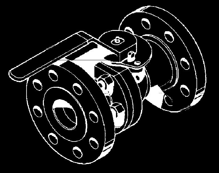

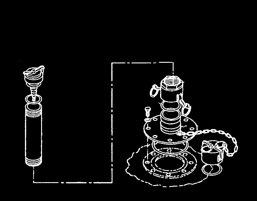

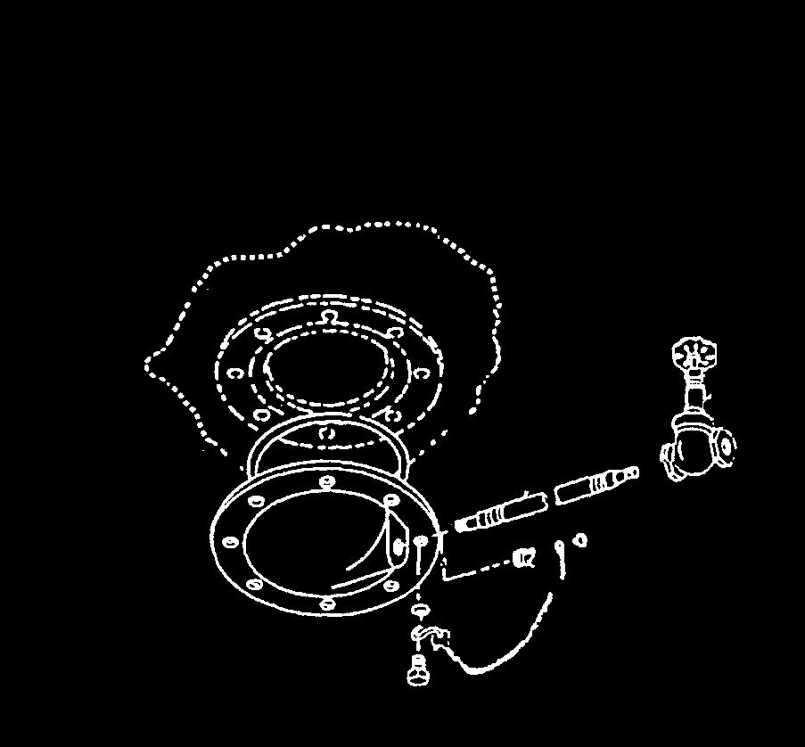
90 TM &P Unit Preventive Maintenance Checks and Services Components
91 TM &P Table 1. Unit Preventive Maintenance Checks and Services for Fuel Storage Tank NOTE Within designated intervals, these checks are to be performed in the order listed. ITEM NO. INTERVAL MAN- HOUR ITEM TO BE CHECKED OR SERVICED PROCEDURE EQUIPMENT NOT READY/ AVAILABLE IF: 1 Before Tank (1) Inspect for tears, punctures, or leaks (Exclude weeping/wicking where the tank seams are not involved and droplets do not form or run down the side of the tank). Torn, punctured, or leaking. 2 Before Filler/Discharge Gate Valve (2) (Models WTM3KF, MIL-T-52983B, M , PD , BA92-162, FCE A, SC CLE01) Check for bent or binding stem, broken hand-wheel, and leakage. Stem, handwheel, gasket, or cam-lever arms are damaged or leaking. 3 Before Filler/Discharge Butterfly Valve Assembly (3) (Models BA & BA91-140) 4 Before Filler/Discharge Ball Valve (4) (Models BA91-141A & BA91-140A) 5 Before Drain Gate Valve (5) (Models WTM3KF, M , BA92-162, FCE A, SC CLE01) Check for bent or binding stem, broken handle, and leakage. Check for bent or binding stem, broken handle, and leakage. Check for bent or binding stem, broken hand-wheel, and leakage. Stem, handle, gasket, camlever arms are damaged or leaks. Stem or handle is damaged or leaks. Stem or handwheel is damaged or leaks
92 TM &P ITEM NO. INTERVAL MAN- HOUR ITEM TO BE CHECKED OR SERVICED PROCEDURE EQUIPMENT NOT READY/ AVAILABLE IF: 6 Before Drain Ball Valve (6) (Models BA & BA91-140, PD , BA91-141A & BA91-140A) Check for bent or binding stem, broken handle, and leakage. Stem or handle is damaged or leaks. 7 Before Vent and Pipe Assembly (7) Check for evidence of leakage, damage or missing parts. Check the relief cap for cleanliness and freedom of operation. Check if the flame arrestor, relief cap gasket, flat rubber gasket or cam-lever arms are damaged or missing. Leaks are evident. Relief cap or flame arrestor is damaged or missing. Relief cap gasket, flat rubber gasket or cam-lever arms are damaged or missing. 8 Before Filler/Discharge Assembly (8) 9 Before Drain Fitting Assembly (9) (Except Models MIL-T-52983B, BA91-141, BA91-140) Drain Fitting Assembly (10) (Models BA and BA91-140) Check for evidence of damage or leakage. Check if cam-lever arms are damaged or missing. Check if the elbow body is cracked or sealing surface is badly dented. Check for loose, damaged or missing screws and gaskets. Check immediate area for evidence of leakage. Check drain plug, drain hose, or drain valve, for damaged or missing parts. Cam-lever arms are damaged or missing. Elbow body is cracked. Elbow sealing surface is badly dented. Hardware is damaged or missing. Drain plug, drain hose, drain gate, or ball valve is missing, not properly connected, damaged or leaks. 10 During Tank (1) Inspect for tears, punctures, or leaks (Exclude weeping/wicking where the tank seams are not involved and droplets do not form or run down the side of the tank). Tank has tears or punctures that cannot be repaired
93 TM &P ITEM NO. INTERVAL MAN- HOUR ITEM TO BE CHECKED OR SERVICED 11 During Filler/Discharge Gate Valve (2) (Models WTM3KF, MIL- T-52983B, M , PD , BA92-162, FCE A, SC CLE01) 12 During Filler/Discharge Butterfly Valve Assembly (3) (Models BA & BA91-140) 13 During Filler/Discharge Ball Valve (4) (Models BA91-141A & BA91-140A) 14 During Drain Gate Valve (5) (Models WTM3KF, M , BA92-162, FCE A, SC CLE01) 15 During Drain Ball Valve (6) (Models BA & BA91-140, PD , BA91-141A & BA91-140A) 16 During Vent and Pipe Assembly (7) PROCEDURE Check for bent or binding stem, broken hand-wheel, and leakage. Check for bent or binding stem, broken handle, and leakage. Check for bent or binding stem, broken handle, and leakage. Check for bent or binding stem, broken hand-wheel, and leakage. Check for bent or binding stem, broken handle, and leakage. Check for evidence of leakage, damage, or missing parts. Check the relief cap for cleanliness and freedom of operation. Check if the flame arrestor, relief cap gasket, flat rubber gasket, or cam-lever arms are damaged or missing. EQUIPMENT NOT READY/ AVAILABLE IF: Stem, handwheel, gasket, or cam-lever arms are damaged, missing, or leaks. Stem, handle, gasket, camlever arms are damaged or leaks. Stem or handle is damaged or leaks. Stem or handwheel is damaged, missing, or leaks. Stem or handle damaged, missing, or leaks. Relief cap or flame arrestor is damaged or missing. Relief cap gasket, flat rubber gasket, or cam-lever arms are damaged or missing
94 TM &P ITEM NO. INTERVAL MAN- HOUR ITEM TO BE CHECKED OR SERVICED 17 During Filler/Discharge Assembly (8) 18 During Drain Fitting Assembly (9) (Except Models MIL-T-52983B, BA91-141, BA91-140) Drain Fitting Assembly (10) (Models BA and BA91-140) PROCEDURE Check for evidence of damage or leakage. Check if cam-lever arms are damaged or missing. Check if the elbow body is cracked or sealing surface is badly dented. Check for loose, damaged or missing screws and gaskets. Check immediate area for any evidence of leakage. Check the drain plug, drain hose, or drain valve, for damaged or missing parts. EQUIPMENT NOT READY/ AVAILABLE IF: Cam-lever arms are damaged or missing. Elbow body is cracked. Elbow sealing surface is badly dented. Drain plug, drain hose, drain valve is missing, not properly connected, or damaged. 19 After Tank (1) Inspect for tears, punctures, or leaks (Exclude weeping/wicking where the tank seams are not involved and droplets do not form or run down the side of the tank). Tank has tears or punctures that cannot be repaired. 20 After Filler/Discharge Gate Valve (2) (Models WTM3KF, MIL-T-52983B, M , PD , BA92-162, FCE A, SC CLE01) 21 After Filler/Discharge Butterfly Valve Assembly (3) (Models BA & BA91-140) 22 After Filler/Discharge Ball Valve (4) (Models BA91-141A & BA91-140A) Check for bent or binding stem, broken hand-wheel, and leakage. Check for bent or binding stem, broken handle, and leakage. Check for bent or binding stem, broken handle, and leakage. Stem, handwheel, gasket, or cam-lever arms are damaged or missing. Stem, handle, gasket or camlever arms are damaged. Stem or handle is damaged
95 TM &P ITEM NO. INTERVAL MAN- HOUR ITEM TO BE CHECKED OR SERVICED PROCEDURE EQUIPMENT NOT READY/ AVAILABLE IF: 23 After Drain Gate Valve (5) (Models WTM3KF, M , BA92-162, FCE A, SC CLE01) 24 After Drain Ball Valve (6) (Models BA & BA91-140, PD , BA91-141A & BA91-140A) 25 After Vent and Pipe Assembly (7) 26 After Filler/Discharge Assembly (8) Check for bent or binding stem, broken hand-wheel, and leakage. Check for bent or binding stem, broken handle, and leakage. Check for evidence of leakage, damage, or missing parts. Check the relief cap for cleanliness and freedom of operation. Check if the flame arrestor, relief cap gasket, flat rubber gasket, or cam-lever arms are damaged or missing. Check for evidence of damage or leakage. Check if cam-lever arms are damaged or missing. Check if the elbow body is cracked or sealing surface is badly dented. Check for loose, damaged or missing screws and gaskets. Stem or handwheel is damaged or missing. Stem or handle is damaged or missing. Relief cap or flame arrestor is damaged or missing. Relief cap gasket, flat rubber gasket, or cam-lever arms are damaged or missing. Cam-lever arms damaged or missing. Elbow body cracked or worn. 27 Semiannually Drain Fitting Assembly (9) (Except Models MIL-T-52983B, BA91-141, BA91-140) Drain Fitting Assembly (10) (Models BA and BA91-140) Check immediate area for evidence of leakage. Check the drain plug, drain hose, or drain valve, for damaged or missing parts. Drain plug, drain hose, and drain valve are missing, not properly connected, or damaged. END OF WORK PACKAGE
96 TM &P GENERAL INSTRUCTIONS OPERATOR AND UNIT MAINTENANCE MANUAL (INCLUDING REPAIR PARTS AND SPECIAL TOOLS LIST) COLLAPSIBLE FABRIC TANKS, FUEL STORAGE, 3,000, 10,000, 20,000, AND 50,000 GALLON UNIT MAINTENANCE PROCEDURES Maintenance instructions in this section will list resources required, personnel required and equipment conditions for start of procedure, except as noted below: NOTE Personnel required are listed only if the task requires more than one. EQUIPMENT MAINTENANCE PROCEDURE Filler/Discharge Gate Valve Assembly (Models WTM3KF, MIL-T-52983B, PD , M , BA92-162, FCE A, SC CLE01) Service, Replacement, and Repair... WP Filler/Discharge Butterfly Valve Assembly (Models BA91-141, BA91-140) Service, Replacement, and Repair... WP Filler/Discharge Ball Valve Assembly (Models BA91-141A, BA91-140A) Replacement... WP Filler/Discharge Hose Assembly Service and Replacement... WP Drain Gate Valve (Models WTM3KF, M , BA92-162, FCE A, SC CLE01) Service, Replacement, Repair... WP Drain Ball Valve (Models BA91-141, BA91-140, PD , BA91-141A, BA91-140A) Service, Replacement, Repair... WP Drain Hose Assembly (Except Model MIL-T-52983B) Service... WP Vent and Pipe Assembly Service and Repair... WP Filler/Discharge Assembly Service, Replacement, Repair... WP Drain Fitting Assembly (Except Models MIL-T-52983B, BA91-141, BA91-140) Service and Repair... WP Drain Fitting Assembly (Models BA91-141, BA91-140) Service and Repair... WP Tank Assembly Service... WP END OF WORK PACKAGE /2 blank
97
98 TM &P OPERATOR AND UNIT MAINTENANCE MANUAL (INCLUDING REPAIR PARTS AND SPECIAL TOOLS LIST) COLLAPSIBLE FABRIC TANKS, FUEL STORAGE, 3,000, 10,000, 20,000, AND 50,000 GALLON FILLER/DISCHARGE GATE VALVE ASSEMBLY (MODELS WTM3KF, MIL-T-52983B, PD , M , BA92-162, FCE A, SC CLE01) SERVICE, REPLACEMENT, REPAIR INITIAL SETUP Tools Equipment Condition Tool Kit General Mechanics Fuel tank drained (Item 1, WP ) (WP ) Torque Wrench (in-lb) (Item 2, WP ) Torque Wrench (ft-lb) (Item 3, WP ) Materials/Parts Mandatory Replacement Parts Crocus Cloth Gasket (Item 2, WP ) (Item 1, WP ) Detergent Gaskets (Item 3, WP ) (Item 3, WP ) Dry Cleaning Solvent Gasket, Valve Bonnet (Item 4, WP ) (Item 5, WP ) Grease Lockwashers (Item 5, WP ) (Item 4, WP ) Rags, wiping Lockwashers (Item 6, WP ) (Item 6, WP ) REMOVAL Hose Assembly, Coupling, and Adapter 1. Remove hose assembly (1) from gate valve assembly (2) by pulling two cam-lever arms (3) outward on female quick-disconnect coupling (4). 2. Remove hose assembly (1). 3. Remove the chain and dust cap (5) from female quick-disconnect coupling (4), and the chain and dust plug (6) from male-flanged adapter (7). Remove gasket (8) from male-flanged adapter (7). 4. Remove coupling gasket (9) from inside female quick-disconnect coupling (4). 5. Remove eight hex nuts (10), lockwashers (11), hex-head cap screws (12), and washers (13). 6. Remove female quick-disconnect coupling (4) and flange gasket (14) from face of gate valve (15). 7. Remove eight hex nuts (16), lockwashers (17), hex-head cap screws (18), and washers (19) from the opposite end of gate valve (15). 8. Remove male-flanged adapter (7) and flange gasket (20)
99 TM &P
100 TM &P DISASSEMBLY Gate Valve 1. Remove jam nut (1) from the top of hand-wheel (2). 2. Remove hand-wheel (2) from the top of valve stem (3). 3. Remove packing nut (4) from bonnet (5). 4. Remove packing gland (6) and gland spring (7) from valve stem (3). NOTE The packing ring will remain in the bonnet until the valve stem, the disk riser, and the disk halves have been removed from the bonnet. 5. Remove eight hex nuts (8), lockwashers (9), and hex-head cap screws (10) holding bonnet (5) to valve body (11). CAUTION Keep the disk halves together when removing from the valve body. Disk halves must be grasped firmly when disassembled from the valve body. Dropping the disk halves off the disk riser can damage the sealing surfaces. As the discs clear the slots in the valve body, hold them together with the right hand in order to avoid dropping off the disk stem and damaging the sealing surface. 6. Lift bonnet (5) with valve stem (3), disk riser (12), and disk halves (13) and (14) from valve body (11)
101 TM &P Remove bonnet gasket (15) from valve body (11). 8. Rotate disk riser (12) counterclockwise, and disassemble disk riser (12) from valve stem (3). 9. Rotate valve stem (3) clockwise, and disassemble valve stem (3) from the bottom side of bonnet (5). NOTE The packing ring should be removed only when it is to be replaced. 10. Drive packing ring (16) through the bottom of bonnet (5)
102 TM &P SERVICE WARNING Dry cleaning solvent, A-A-59601, used to clean parts, is potentially dangerous to personnel and property. It produces toxic and flammable fumes. Use only in well ventilated areas. Avoid repeated and prolonged skin contact. Do not use solvent near an open flame or near excessive heat. The flash point of the solvent is 100 F to 130 F (38 C to 59 C). 1. Clean all parts with dry cleaning solvent and dry thoroughly with rags. 2. Clean all gasket-sealing surfaces thoroughly with detergent and hot water. 3. Inspect all mechanical parts for cracks, dents, breaks, and wear. Replace components if unserviceable. 4. Polish valve stem (3) with crocus cloth. Coat valve stem (3) with grease. ASSEMBLY Gate Valve 1. Thread disk riser (12) into valve stem (3). 2. Check that disk riser (12) is completely secured to bonnet (5). 3. Lay valve body (11) on its side on a clean surface. Position new gasket (15) over disk riser (12). 4. Install disk halves (13) and (14) onto disk riser (12). 5. Insert disk halves (13) and (14) into valve body (11) slot. 6. Place valve body (11) and bonnet (5) in an upright position. 7. Align valve body (11) to gasket (15). Install bonnet (5) assembly to valve body (11) with eight hexhead cap screws (10), new lockwashers (9), and hex nuts (8). 8. Insert packing ring (16) onto valve stem (3). 9. Insert packing nut (4) onto valve stem (3) by pushing packing nut (4) down on the neck of bonnet (5) until packing ring (16) is seated in bonnet (5). 10. Remove packing nut (4) from valve stem (3), and assemble gland spring (7) and packing gland (6) to valve stem (3). 11. Insert packing nut (4), hand-wheel (2), and jam nut (1) onto the valve stem (3). 12. Torque hex-head cap screws (10), lockwashers (9), and hex nuts (8) assembled to the valve body (11) to 16 ft-lb (21.84 Nm)
103 TM &P INSTALLATION Hose Assembly, Coupling, and Adapter 1. Position new flange gasket (20) on the face of gate valve (15), and align the holes. 2. Position male-flanged adapter (7) against flange gasket (20), and align the holes. 3. Install washers (19) and hex-head cap screws (18) onto male-flanged adapter (7), flange gasket (20), and gate valve (15). 4. Install new lockwashers (17), and hex nuts (16) onto gate valve (15). Torque nuts (16) to 30 in-lb (3.41N m). 5. At the opposite end of gate valve (15), position new flange gasket (14) against gate valve (15). 6. Position female quick-disconnect coupling (4) against flange gasket (14) and align the holes. 7. Install washers (13) and hex-head cap screws (12) onto female quick-disconnect coupling (4), flange gasket (14), and the face of gate valve (15). 8. Install new lockwashers (11) and hex nuts (10) onto hex-head cap screws (12). Torque nuts (10) to 30 in-lb (3.41N m). 9. Lubricate new coupling gasket (9), and install coupling gasket (9) on the inside of female quickdisconnect coupling (4). 10. Install new gasket (8) on male-flanged adapter (7). Install chains and dust cap (5) and dust plug (6) on coupling (4) and adapter (7). 11. Install hose assembly (1) to gate valve assembly (2) and position hose assembly (1) in place by pushing in on cam-lever arms (3). END OF WORK PACKAGE
104 TM &P OPERATOR AND UNIT MAINTENANCE MANUAL (INCLUDING REPAIR PARTS AND SPECIAL TOOLS LIST) COLLAPSIBLE FABRIC TANKS, FUEL STORAGE, 3,000, 10,000, 20,000, AND 50,000 GALLON FILLER/DISCHARGE BUTTERFLY VALVE ASSEMBLY (MODELS BA91-141, BA91-140) SERVICE, REPLACEMENT, AND REPAIR INITIAL SETUP Tools Equipment Condition Tool Kit General Mechanics Fuel tank drained (Item 1, WP ) (WP ) Torque Wrench (in-lb) (Item 2, WP ) Materials/Parts Mandatory Replacement Parts Detergent Gasket (Item 3, WP ) (Item 1, WP ) Rags, Wiping Gasket (Item 6, WP (Item 3, WP ) Lockwashers (Item 4, WP ) Parts Kit, Butterfly (Item 8, WP ) Parts Kit, Valve (Item 7, WP ) REMOVAL 1. Disconnect ring (1) and remove dust cap (2) from male coupling (3). 2. Remove gasket (4) from dust cap (2). 3. Remove chain (5) and dust plug (6) from female coupling (7). 4. Remove nuts (8), lockwashers (9), washers (10) and (11) and screws (12). 5. Remove female coupling (7) and gasket (13), and male coupling (3) and gasket (14) from butterfly valve (15). 6. Remove gasket (16) from female coupling (7). 7. Inspect dust cap (2), male coupling (3), and female coupling (7) for cracks and corrosion. Replace damaged parts
105 TM &P
106 TM &P DISASSEMBLY 1. Remove cotter pin (1) and pin (2) from handle (3). 2. Lift handle (3) and attached spring (4) from valve stem (5). 3. Remove two socket head screws (6) and stop plate (7) from valve body (8). 4. Remove top seal (9) from the bottom of stop plate (7). 5. Remove top valve stem (5) assembly from valve body (8). 6. Remove seal (10), O-ring (11), top bearing (12), and O-ring (13) from top valve stem (5). 7. Drive spring pin (14) from valve body (8) and bottom valve stem (15). 8. Remove bottom valve stem (15) assembly from valve body (8). 9. Remove bottom bearing (16) and O-ring (17) from bottom valve stem (15). 10. Remove disk (18) from valve body (8). 11. Remove sleeve (19) from valve body (8). SERVICE 1. Wash all components with clean hot water and detergent. 2. Rinse components in clean water and dry with rags. 3. Inspect the valve body, handle, disc, and stop plate for cracks and corrosion. 4. Inspect the top valve stem and bottom valve stem for cracks, deep scratches, and corrosion. 5. Replace damaged parts
107 TM &P
108 TM &P ASSEMBLY 1. Install sleeve (19) into valve body (8) and align the fastening holes of sleeve (19) with those of valve body (8). NOTE The bottom hole in the disk is round and smooth. The top hole is slotted to fit on the end of the top stem. 2. Install disk (18) into valve body (8) and align the fastening holes of disk (18) with the holes in sleeve (19) and valve body (8). 3. Install new O-ring (17) and bottom valve bearing (16) onto bottom valve stem (15). 4. Install bottom valve stem (15) through the bottom of valve body (8) and into the bottom hole of disk (18), aligning spring pin (14) hole in valve stem (15) with spring pin (14) hole in valve body (8). 5. Install spring pin (14) into valve body (8) and through bottom valve stem (15). 6. Install new O-ring (13), top bearing (12), and new O-ring (11) onto the bottom of top valve stem (5). 7. Install new seal (10) on top valve stem (5). 8. Align the end of top valve stem (5) with the hole in disk (18). 9. Install valve stem (5) assembly through valve body (8) and into the slot located in disk (18), ensuring valve stem (5) is fully seated in disk (18). 10. Install new top seal (9) at the bottom of stop plate (7). 11. Position stop plate (7) on valve body (8), and install two socket head screws (6). 12. Rotate disk (18) to the open position. 13. Position handle (3) and attach spring (4) on top of valve stem (5), so that handle (3) is in line with disk (18). NOTE Press handle down against the spring to align the holes with top valve stem. 14. Install pin (2) through handle (3) and top valve stem (5), securing pin (2) to handle (3) with a new cotter pin (1). INSTALLATION NOTE Check that gasket is fully seated in the coupling groove. 1. Install new gasket (16) into female coupling (7). 2. Position new gasket (13) and female coupling (7) on butterfly valve (15). 3. Position new gasket (14) and male coupling (3) on butterfly valve (15)
109 TM &P Install eight washers (11), screws (12), washers (10), new lockwashers (9), and nuts (8) on butterfly valve assembly. Torque the fastening hardware to 30 in-lbs (3.41N m). 5. Install new gasket (4) into dust cap (2). 6. Connect ring (1) and install dust cap (2) onto male coupling (3). END OF WORK PACKAGE
110 TM &P OPERATOR AND UNIT MAINTENANCE MANUAL (INCLUDING REPAIR PARTS AND SPECIAL TOOLS LIST) COLLAPSIBLE FABRIC TANKS, FUEL STORAGE, 3,000, 10,000, 20,000, AND 50,000 GALLON FILLER/DISCHARGE BALL VALVE ASSEMBLY (MODELS BA91-141A, BA91-140A) REPLACEMENT INITIAL SETUP Tools Equipment Condition Tool Kit General Mechanics Fuel tank drained (Item 1, WP ) (WP ) Torque Wrench (in-lb) (Item 2, WP ) Mandatory Replacement Parts Gaskets (Item 3, WP ) Lockwashers (Item 4, WP ) REMOVAL 1. Disconnect chains (1) from key rings (2) and remove dust cap (3), and dust plug (4). Remove gaskets (5) from dust cap (3) and female coupling (6). 2. Remove eight nuts (7), lockwashers (8), washers (9), and screws (10) from female coupling (6) and ball valve (11). 3. Remove female coupling (6) and flange gasket (12) from ball valve (11). 4. Remove other eight nuts (7), lockwashers (8), washers (9), and screws (10) from male coupling (13) and ball valve (11). 5. Remove male coupling (13) and flange gasket (14) from ball valve (11). 6. Inspect ball valve (11) for damage. Replace ball valve (11) if damaged
111 TM &P INSTALLATION 1. Align male coupling (13) and new flange gasket (14) on ball valve (11). 2. Install eight nuts (7), new lockwashers (8), washers (9), and screws (10) to male coupling (13) and ball valve (11). Torque the fastening hardware to 30 in-lbs (3.41N m). 3. Align female coupling (6) and new flange gasket (12) on ball valve (11). 4. Install eight nuts (7), new lockwashers (8), washers (9), and screws (10) to female coupling (6) and ball valve (11). Torque the fastening hardware to 30 in-lbs (3.41 N m). 5. Install new gaskets (5) in female coupling (6) and dust cap (3). 6. Connect chains (1) to key rings (2) and install dust cap (3) and dust plug (4) to female coupling (6) and male coupling (13). END OF WORK PACKAGE
112 TM &P OPERATOR AND UNIT MAINTENANCE MANUAL (INCLUDING REPAIR PARTS AND SPECIAL TOOLS LIST) COLLAPSIBLE FABRIC TANKS, FUEL STORAGE, 3,000, 10,000, 20,000, AND 50,000 GALLON FILLER/DISCHARGE HOSE ASSEMBLY SERVICE AND REPLACEMENT INITIAL SETUP Materials/Parts Equipment Condition Detergent Fuel tank drained (Item 3, WP ) (WP ) REMOVAL Mandatory Replacement Parts Gasket (Item 1, WP ) 1. Pull outward on two cam-lever arms (1). Remove dust cap (2) and dust plug (3) from hose assembly (4). 2. Remove two chain assemblies (5) and remove dust cap (2) and dust plug (3) from hose assembly (4). 3. Remove gasket (6) from dust cap (2). SERVICE 1. Flush out the hose assembly with hot, soapy water. 2. Rinse out the filler/discharge hose assembly thoroughly and air-dry. 3. Inspect the hose for cracks, tears, or wear, and ensure that the hose bands are secure to the couplings. 4. Inspect all mechanical parts for cracks, dents, breaks and wear. Replace any unserviceable components
113 TM &P INSTALLATION 1. Install two chain assemblies (5), dust cap (2), and dust plug (3) to hose assembly (4). Install new gasket (6) in dust cap (2). 2. Connect dust cap (2) and dust plug (3) to hose assembly (4) by pushing in on cam-lever arms (1). END OF WORK PACKAGE
114 TM &P OPERATOR AND UNIT MAINTENANCE MANUAL (INCLUDING REPAIR PARTS AND SPECIAL TOOLS LIST) COLLAPSIBLE FABRIC TANKS, FUEL STORAGE, 3,000, 10,000, 20,000, AND 50,000 GALLON DRAIN GATE VALVE (MODELS WTM3KF, M , BA92-162, FCE A, SC CLE01) SERVICE, REPLACEMENT, REPAIR INITIAL SETUP Tools Equipment Condition Tool Kit General Mechanics Fuel tank drained (Item 1, WP ) (WP ) Materials/Parts Mandatory Replacement Parts Anti-seize Tape Packing Material (Item 7, WP ) (Item 10, WP ) Crocus Cloth (Item 2, WP ) Dry Cleaning Solvent (Item 4, WP ) Grease (Item 5, WP ) Rags, Wiping (Item 6, WP ) Thread Sealing Compound (Item 8, WP ) REMOVAL 1. Remove drain gate valve (1) from drain hose assembly (2). WARNING Dry cleaning solvent, A-A-59601, used to clean parts, is potentially dangerous to personnel and property. It produces toxic and flammable fumes. Use only in well ventilated areas. Avoid repeated and prolonged skin contact. Do not use solvent near an open flame or near excessive heat. The flash point of the solvent is 100 F to 130 F (38 C to 59 C). 2. Clean threads (3) of drain hose assembly (2) with dry cleaning solvent and dry with rags
115 TM &P DISASSEMBLY 1. Remove hand-wheel nut (1) from hand-wheel (2). 2. Remove hand-wheel (2) and identification plate (3) from top of valve stem (4). 3. Remove packing nut (5) from bonnet (6). 4. Remove packing retainer (7) from bonnet (6). 5. Remove bonnet (6) from valve body (8). 6. Remove wedge disks (9) from valve stem (4). 7. Remove valve stem (4) from bonnet (6). 8. Remove packing material (10) from bonnet (6)
116 TM &P SERVICE WARNING Dry cleaning solvent, A-A-59601, used to clean parts, is potentially dangerous to personnel and property. It produces toxic and flammable fumes. Use only in well ventilated areas. Avoid repeated and prolonged skin contact. Do not use solvent near an open flame or near excessive heat. The flash point of the solvent is 100 F to 130 F (38 C to 59 C). 1. Clean all parts with dry cleaning solvent and dry thoroughly with rags. 2. Inspect all mechanical parts for cracks, dents, breaks, and wear. Replace the component if unserviceable. 3. Polish the valve stem with a crocus cloth, then coat the valve stem with grease. ASSEMBLY 1. Position valve body (8) on its side on a clean surface. 2. Insert wedge disks (9) into valve body (8) slot. 3. Install new packing material (10) into bonnet (6). 4. Insert valve stem (4) into bonnet (6). 5. Install bonnet (6) into valve body (8). 6. Install packing retainer (7) into bonnet (6). 7. Install packing nut (5) onto bonnet (6). 8. Install hand-wheel (2), hand-wheel nut (1), and identification plate (3) on valve stem (4). INSTALLATION 1. Coat threads (3) of drain hose assembly (2) with thread sealing compound or anti-seize tape. 2. Install drain gate valve (1) on drain hose assembly (2). END OF WORK PACKAGE /4 blank
117
118 TM &P OPERATOR AND UNIT MAINTENANCE MANUAL (INCLUDING REPAIR PARTS AND SPECIAL TOOLS LIST) COLLAPSIBLE FABRIC TANKS, FUEL STORAGE, 3,000, 10,000, 20,000, AND 50,000 GALLON DRAIN BALL VALVE (MODELS BA91-141, BA91-140, PD , BA91-141A, BA91-140A) SERVICE, REPLACEMENT, REPAIR INITIAL SETUP Tools Equipment Condition Tool Kit General Mechanics Fuel tank drained (Item 1, WP ) (WP ) Torque Wrench (ft-lb) (Item 3, WP ) Materials/Parts Mandatory Replacement Parts Anti-seize Tape Bonnet gasket (Item 7, WP ) (Item 11, WP ) Dry Cleaning Solvent Stem Seal (Item 4, WP ) (Item 12, WP ) Grease Stem Seal (Item 5, WP ) (Item 13, WP ) Rags, Wiping (Item 6, WP ) Thread Sealing Compound (Item 8, WP ) REMOVAL Remove the drain ball valve from the drain hose assembly. DISASSEMBLY 1. Remove handle-nut (1) from valve stem (2). 2. Remove handle (3) from valve stem (2). 3. Remove valve stem nut (4) from valve stem (2). 4. Remove travel stop (5), gland ring (6), and valve stem seal (7) from valve stem (2). Discard seal (7). 5. Remove cap screws (8) from bonnet (9). Remove bonnet (9) from valve body (10). 6. Remove valve stem (2), valve stem seal (11), spring (12), bonnet gasket (13), ball (14), and two ball seats (15) from valve body (10). Discard seal (11) and bonnet gasket (13). SERVICE WARNING Dry cleaning solvent, A-A-59601, used to clean parts, is potentially dangerous to personnel and property. It produces toxic and flammable fumes. Use only in well ventilated areas. Avoid repeated and prolonged skin contact. Do not use solvent near an open flame or near excessive heat. The flash point of the solvent is 100 F to 130 F (38 C to 59 C). 1. Clean all parts with dry cleaning solvent and dry thoroughly with rags
119 TM &P Inspect all mechanical parts for cracks, dents, breaks, and wear. Replace the component if unserviceable. 3. Polish the valve stem with a crocus cloth, then coat the valve stem with grease ASSEMBLY 1. Install two ball seats (15) into valve body (10). 2. Install new bonnet gasket (13) into valve body (10). 3. Install ball (14) into valve body (10). 4. Install new valve stem seal (11) and spring (12) at the bottom of valve stem (2). Insert valve stem (2) into valve body (10)
120 TM &P Position bonnet (9) over valve stem (2) and install four cap screws (8). Torque cap screws (8) to 16 ft-lbs (21.04 N m). 6. Install new valve stem seal (7), gland ring (6), travel stop (5), and valve stem nut (4) onto valve stem (2). 7. Position handle (3) on valve stem (2). Install and tighten handle-nut (1) on valve stem (2). INSTALLATION Coat the threads of the drain hose assembly with thread sealing compound or anti-seize tape, and install the drain ball valve on the drain hose assembly. END OF WORK PACKAGE /4 blank
121
122 TM &P OPERATOR AND UNIT MAINTENANCE MANUAL (INCLUDING REPAIR PARTS AND SPECIAL TOOLS LIST) COLLAPSIBLE FABRIC TANKS, FUEL STORAGE, 3,000, 10,000, 20,000, AND 50,000 GALLON DRAIN HOSE ASSEMBLY (EXCEPT MODEL MIL-T-52983B) SERVICE INITIAL SETUP Materials/Parts Equipment Condition Anti-seize Tape Fuel tank drained (Item 7, WP ) (WP ) Detergent Drain Gate/Ball Valve removed (Item 3, WP ) (WP or WP ) Dry Cleaning Solvent (Item 4, WP ) Rags, Wiping (Item 6, WP ) Sealing Compound (Item 8, WP ) SERVICE 1. Rotate hose assembly (1) counterclockwise and remove from drain fitting (2). 2. Flush hose assembly (1) with hot, soapy water. 3. Rinse out hose assembly (1) thoroughly and air dry. WARNING Dry cleaning solvent, A-A-59601, used to clean parts, is potentially dangerous to personnel and property. It produces toxic and flammable fumes. Use only in well ventilated areas. Avoid repeated and prolonged skin contact. Do not use solvent near an open flame or near excessive heat. The flash point of the solvent is 100 F to 130 F (38 C to 59 C). 4. Clean the threads on couplings (3) with dry cleaning solvent and dry thoroughly with rags. 5. Inspect hose assembly (1) for cracks, tears, or wear. 6. Check and ensure hose bands (4) are secured to threaded couplings (3). 7. Apply sealing compound or anti-seize tape on threads of coupling (3). Engage threads of couplings (3) with threads on drain fitting (2) and turn hose assembly (1) clockwise until tight. 8. Install the drain gate or ball valve. See WP and WP
123 TM &P END OF WORK PACKAGE
124 TM &P OPERATOR AND UNIT MAINTENANCE MANUAL (INCLUDING REPAIR PARTS AND SPECIAL TOOLS LIST) COLLAPSIBLE FABRIC TANKS, FUEL STORAGE, 3,000, 10,000, 20,000, AND 50,000 GALLON VENT AND PIPE ASSEMBLY SERVICE, REPLACEMENT, REPAIR INITIAL SETUP Tools Equipment Condition Tool Kit General Mechanics Fuel tank drained (Item 1, WP ) (WP ) Torque Wrench (in-lb) (Item 2, WP ) Materials/Parts Mandatory Replacement Parts Dry Cleaning Solvent Gasket (Item 4, WP ) (Item 2, WP ) Rags, Wiping Gasket Cap (Item 6, WP ) (Item 14, WP ) Silicone Compound O-Ring (Item 9, WP ) (Item 15, WP ) Relief Cap Gasket (Item 16, WP ) REMOVAL 1. Remove screws (1) and washers (2) from vent and pipe assembly (3). 2. Lift male-flanged adapter (4) from tank fitting (5). 3. Remove and discard O-ring (6) from packing groove (7) located in tank fitting (5). DISASSEMBLY 1. Remove female quick-disconnect coupling (8) from male-flanged adapter (4) by pulling outward on cam-lever arms (9), and lifting female quick-disconnect coupling (8) from male-flanged adapter (4). 2. Remove and discard gasket (10) from female quick-disconnect coupling (8). 3. Rotate vent pipe (11) counterclockwise until the vent pipe threads disengage from female quick-disconnect coupling (8), and remove female quick-disconnect coupling (8) from vent pipe (11). 4. Rotate relief cap (12) counterclockwise until the relief cap threads disengage from vent pipe (11). Remove the relief cap (12) from the vent pipe (11). 5. Remove and discard relief cap gasket (13) from inside relief cap (12). 6. Rotate flame arrestor (14) counterclockwise until the flame arrestor threads disengage from relief cap (12). Remove flame arrestor (14) from relief cap (12). 7. Remove and discard gasket (15) from inside dust cap (16). 8. Remove vent relief cap screw (17), washer (18), and gasket (19) from lever head assembly (20). Discard gasket (19)
125 TM &P
126 TM &P SERVICE WARNING Dry cleaning solvent, A-A-59601, used to clean parts, is potentially dangerous to personnel and property. It produces toxic and flammable fumes. Use only in well ventilated areas. Avoid repeated and prolonged skin contact. Do not use solvent near an open flame or near excessive heat. The flash point of the solvent is 100 F to 130 F (38 C to 59 C). 1. Clean all parts with dry cleaning solvent, and dry thoroughly with rags. 2. Clean the preformed packing grooves with cleaning solvent, and dry thoroughly with rags. 3. Inspect all mechanical parts for cracks, dents, breaks, and wear. Replace the component if unserviceable. 4. Check that the vent hole in the flame arrestor is clear of all debris. ASSEMBLY 1. Install screw (17), washer (18), and new gasket (19) in lever head assembly (20). 2. Position new relief cap gasket (13) over flame arrestor (14). Seat relief cap gasket (13) into relief cap (12). 3. Install flame arrestor (14) into relief cap (12). Rotate flame arrestor (14) clockwise until threads are firmly seated in relief cap (12). 4. Install flame arrestor (14) into vent pipe (11) until vent pipe (11) contacts relief cap (12). 5. Rotate relief cap (12) clockwise until vent pipe (11) and relief cap (12) are firmly seated together. 6. Install vent pipe (11) into female quick-disconnect coupling (8). Rotate vent pipe (11) clockwise until it firmly seats in female quick-disconnect coupling (8). 7. Install new gasket (10) into female quick-disconnect coupling (8). 8. Install female quick-disconnect coupling (8) on male-flanged adapter (4) pushing in cam-lever arms (9) until locked in place. 9. Install new gasket (15) inside dust cap (16). INSTALLATION 1. Lubricate new O-ring (6) with silicone compound. 2. Install O-ring (6) into packing groove (7) located in tank fitting (5). 3. Position male-flanged adapter (4) over tank fitting (5). 4. Install eight washers (2) and screws (1) through vent and pipe assembly (3) and tank fitting (5) holes. 5. Torque screws (1) to 30 in-lb (3.41 N m). END OF WORK PACKAGE /4 blank
127
128 TM &P OPERATOR AND UNIT MAINTENANCE MANUAL (INCLUDING REPAIR PARTS AND SPECIAL TOOLS LIST) COLLAPSIBLE FABRIC TANKS, FUEL STORAGE, 3,000, 10,000, 20,000, AND 50,000 GALLON FILLER/DISCHARGE ASSEMBLY SERVICE AND REPAIR INITIAL SETUP Tools Equipment Condition Tool Kit General Mechanics Fuel tank drained (Item 1, WP ) (WP ) Torque Wrench (in-lb) Filler/Discharge hose removed (Item 2, WP ) (WP ) Materials/Parts Mandatory Replacement Parts Detergent Gasket (Item 3, WP ) (Item 1, WP ) Dry Cleaning Solvent Gasket (Item 4, WP ) (Item 3, WP ) Rags, Wiping Gasket (Item 6, WP ) (Item 18, WP ) Silicone Compound Lockwasher (Item 9, WP ) (Item 4, WP ) O-Ring (Item 17, WP ) DISASSEMBLY CAUTION Be sure to take off the closure plate before removing the flanged adapter. The flanged adapter is bolted to the closure plate and suction stub. If the flanged adapter is removed first, the hex head nuts bolted to the suction stub will fall into the tank. NOTE The filler/discharge fitting on the discharge end requires a female/male elbow. The filler/discharge fitting on the fill end requires a female/female elbow. 1. Remove 4-inch elbow (1) by pulling outward on cam-lever arms (2), and lifting elbow (1) from flanged adapter (3). 2. Remove and discard elbow gasket (4) from inside elbow (1). 3. Remove twenty screws (5) and washers (6) from closure plate (7). Lift closure plate (7) from tank fitting (8). 4. Remove and discard o-ring (9) from the packing groove located in tank fitting (8). 5. Remove eight nuts (10), lockwashers (11), screws (12), and gaskets (13) from suction stub (14), flanged adapter (3), and gasket (15). Discard lockwashers (11), gaskets (13), and gasket (15). 6. Remove and discard gasket (16) from inside dust cap (17)
129 TM &P SERVICE WARNING Dry cleaning solvent, A-A-59601, used to clean parts, is potentially dangerous to personnel and property. It produces toxic and flammable fumes. Use only in well ventilated areas. Avoid repeated and prolonged skin contact. Do not use solvent near an open flame or near excessive heat. The flash point of the solvent is 100 F to 130 F (38 C to 59 C). 1. Clean all parts with dry cleaning solvent and dry thoroughly with rags. 2. Clean packing grooves thoroughly with detergent and hot water. 3. Clean all gasket-sealing surfaces thoroughly with detergent and hot water. 4. Inspect all mechanical parts for cracks, dents, breaks, and wear. Replace the component if unserviceable
130 TM &P ASSEMBLY 1. Install new gasket (16) into dust cap (17). 2. Install new elbow gasket (4) into elbow (1). 3. Place suction stub (14) on a hard, flat surface with the eight bolt holes positioned up. 4. Position new gaskets (13) over each bolt hole in suction stub (14). 5. Position closure plate (7) on top of gaskets (13), and align the holes. 6. Position new flanged adapter gasket (15) on closure plate (7), and align the holes. 7. Position flanged adapter (3) on gasket (15), and align the holes. 8. Install screws (12) through the holes in flanged adapter (3), and thread screws (12) through until the ends protrude through suction stub (14). 9. Assemble new lockwashers (11) and nuts (10) to screws (12). Torque the fastening hardware to 30 in-lbs (3.41N m). 10. Lubricate new o-ring (9) with silicone compound. Position o-ring (9) into the packing groove. 11. Position closure plate (7) and attached components on the tank. Install suction stub (14) through the opening in the tank, until closure plate (7) contacts tank fitting (8). NOTE If the tank is lying completely flat, lift the tank to the closure plate to begin threading the screws through the tank fitting. 12. Assemble twenty washers (6) onto screws (5). Install screws (5) through closure plate (7) and tank fitting (8). 13. Torque fastening screws (5) to 30 in-lbs (3.41 N m). 14. Position elbow (1) on flanged adapter (3), and push cam-lever arms (2) inward, locking elbow (1) to flanged adapter (3). END OF WORK PACKAGE /4 blank
131
132 TM &P OPERATOR AND UNIT MAINTENANCE MANUAL (INCLUDING REPAIR PARTS AND SPECIAL TOOLS LIST) COLLAPSIBLE FABRIC TANKS, FUEL STORAGE, 3,000, 10,000, 20,000, AND 50,000 GALLON DRAIN FITTING ASSEMBLY (EXCEPT MODELS MIL-T-52983B BA91-141, BA91-140) SERVICE AND REPAIR INITIAL SETUP Tools Equipment Condition Tool Kit General Mechanics Fuel tank drained (Item 1, WP ) (WP ) Torque Wrench (in-lb) (Item 2, WP ) Materials/Parts Mandatory Replacement Parts Antiseize Tape O-ring (Item 7, WP ) (Item 15, WP ) Detergent (Item 3, WP ) Dry Cleaning Solvent (Item 4, WP ) Rags, Wiping (Item 6, WP ) Sealing Compound (Item 8, WP ) Silicone Compound (Item 9, WP ) DISASSEMBLY 1. Rotate gate valve (1) counterclockwise until the threads disengage from drain hose (2). Remove from drain hose (2). 2. Rotate drain hose (2) counterclockwise until the threads disengage from drain cover plate (3). Remove from drain cover plate (3). 3. Disconnect chain assembly (4). Remove drain plug screw (5) and drain plug (6) from cover plate (3). 4. Remove eight screws (7) and washers (8) from drain cover plate (3) and tank fitting. 5. Remove drain cover plate (3). 6. Remove o-ring (9) from the packing groove located in the tank fitting. Discard o-ring (9)
133 TM &P SERVICE WARNING Dry cleaning solvent, A-A-59601, used to clean parts, is potentially dangerous to personnel and property. It produces toxic and flammable fumes. Use only in well ventilated areas. Avoid repeated and prolonged skin contact. Do not use solvent near an open flame or near excessive heat. The flash point of the solvent is 100 F to 130 F (38 C to 59 C). 1. Clean all parts with dry cleaning solvent and dry thoroughly with rags. 2. Clean packing grooves thoroughly with detergent and hot water. 3. Inspect all mechanical parts for cracks, dents, breaks, and wear. Replace the component if unserviceable ASSEMBLY 1. Lubricate new o-ring (9) with silicone compound. Position o-ring (9) into the packing groove located on the tank fitting. 2. Position drain cover plate (3) on the tank fitting, and align the fastening holes. 3. Install drain cover plate (3) to the tank fitting with screws (7) and washers (8), hand tightening screws (7) and washers (8). 4. Attach the S-hook of chain assembly (4) under one screw (7) head. Torque all screws (7) to 30 in-lbs (3.41 N m). 5. Apply sealing compound or anti-seize tape to drain plug screw (5) threads. 6. Attach chain assembly (4) to drain plug (6), drain plug screw (5), and drain cover plate (3). 7. Screw drain hose (2) clockwise until firmly engaged in drain cover plate (3). 8. Screw gate valve (1) clockwise until firmly engaged with drain hose (2). END OF WORK PACKAGE
134 TM &P OPERATOR AND UNIT MAINTENANCE MANUAL (INCLUDING REPAIR PARTS AND SPECIAL TOOLS LIST) COLLAPSIBLE FABRIC TANKS, FUEL STORAGE, 10,000 AND 20,000 GALLON DRAIN FITTING ASSEMBLY (MODELS BA and BA91-140) SERVICE AND REPAIR INITIAL SETUP Tools Equipment Condition Tool Kit General Mechanics Fuel tank drained (Item 1, WP ) (WP ) Torque Wrench (in-lb) (Item 2, WP ) Materials/Parts Mandatory Replacement Parts Antiseize Tape O-Ring (Item 7, WP ) (Item 15, WP ) Detergent (Item 3, WP ) Dry Cleaning Solvent (Item 4, WP ) Rags, Wiping (Item 6, WP ) Sealing Compound (Item 8, WP ) Silicone Compound (Item 9, WP ) DISASSEMBLY 1. Pull outward on cam-lever arms (1) of dust cap (2). 2. Remove dust cap (2) from female quick-disconnect coupling (3). 3. Pull outward on cam-lever arms (4) of female quick-disconnect coupling (3) 4. Remove female quick-disconnect coupling (3) from flanged adapter (5). 5. Remove chain assembly (6) from flanged adapter (5). 6. Remove eight screws (7) and washers (8) from flanged adapter (5) and tank fitting. 7. Remove flanged adapter (5) and O-ring (9). Discard O-ring (9). SERVICE WARNING Dry cleaning solvent, A-A-59601, used to clean parts, is potentially dangerous to personnel and property. It produces toxic and flammable fumes. Use only in well ventilated areas. Avoid repeated and prolonged skin contact. Do not use solvent near an open flame or near excessive heat. The flash point of the solvent is 100 F to 130 F (38 C to 59 C). 1. Clean all parts with dry cleaning solvent and dry thoroughly with rags
135 TM &P Clean packing groove thoroughly with detergent and hot water. 3. Inspect all mechanical parts for cracks, dents, breaks, and wear. Replace the component if unserviceable ASSEMBLY 1. Attach chain assembly (6) to flanged adapter (5). 2. Apply sealing compound or anti-seize tape to screws (7) threads. 3. Lubricate new O-ring (9) with silicone compound. Position O-ring (9) into groove on the tank fitting. 4. Position flanged adapter (5) on the tank fitting, and align the fastening holes. 5. Install flanged adapter (5) to the tank fitting with screws (7) and washers (8). 6. Torque screws (7) to 30 in-lbs (3.41 N m). 7. Connect female quick-disconnect coupling (3) to flanged adapter (5), pushing cam-lever arms (4) in on female quick-disconnect coupling (3). 8. Install dust cap (2) on female quick-disconnect (3) and push in on cam-lever arms (1). END OF WORK PACKAGE
136 TM &P OPERATOR AND UNIT MAINTENANCE MANUAL (INCLUDING REPAIR PARTS AND SPECIAL TOOLS LIST) COLLAPSIBLE FABRIC TANKS, FUEL STORAGE, 3,000, 10,000, 20,000, AND 50,000 GALLON TANK ASSEMBLY SERVICE INITIAL SETUP Tools Equipment Condition Tool Kit General Mechanics Fuel tank drained (Item 1, WP ) (WP ) Filler/Discharge hose assembly Materials/Parts disconnected Detergent (WP ) (Item 3, WP ) Dry Cleaning Solvent (Item 4, WP ) Rags, Wiping (Item 6, WP ) REMOVAL 1. Remove the vent and pipe assembly from the vent fitting (WP ). 2. Remove the filler/discharge assemblies (WP ). 3. Remove the drain fitting assembly (WP or WP ). SERVICE WARNING Dry cleaning solvent, A-A-59601, used to clean parts, is potentially dangerous to personnel and property. It produces toxic and flammable fumes. Use only in well ventilated areas. Avoid repeated and prolonged skin contact. Do not use solvent near an open flame or near excessive heat. The flash point of the solvent is 100 F to 130 F (38 C to 59 C). 1. Clean all mechanical parts with dry cleaning solvent and dry thoroughly with rags
137 TM &P Clean the tank exterior with detergent and hot water. 3. Inspect all mechanical parts for cracks, dents, breaks, and wear. Replace the component if unserviceable. INSTALLATION NOTE Prior to the installation of fuel tank assemblies, the drain end of the tank will unroll first. 1. Unroll the tank and unfold the sides, using tank handles to position the tank. 2. Install the drain fitting assemblies (WP or WP ). 3. Install the vent and pipe assembly (WP ). 4. Install the filler/discharge assemblies (WP ). END OF WORK PACKAGE
138 TM &P OPERATOR AND UNIT MAINTENANCE MANUAL (INCLUDING REPAIR PARTS AND SPECIAL TOOLS LIST) COLLAPSIBLE FABRIC TANKS, FUEL STORAGE, 3,000, 10,000, 20,000, AND 50,000 GALLON PREPARATION FOR STORAGE OR SHIPMENT PREPARATION FOR STORAGE OR SHIPMENT WARNING Sludge that accumulates at the bottom of the tank gives off toxic and explosive vapors. Inhaling these vapors can cause lead poisoning. When cleaning the fuel tanks, provide ample ventilation to dissipate harmful fumes. Always wear protective goggles, a breathing apparatus, and other protective gear when cleaning the tank interior. Fuel vapors are toxic and can damage eyes, skin, and lungs. Fuel vapors are extremely flammable. Exercise care to prevent sparks when working near or in the tank. Death or severe personal injury can result if safety precautions are not strictly observed. CAUTION Always handle the tank carefully. Pad the components stored with the tank to avoid chafing during storage or transportation. Rough handling or careless storage can damage the tank. NOTE Prior to storage the tank should be disassembled, purged of all residual fuel and fumes, cleaned, and preserved with all its components for future use. 1. Drain fuel from the tank (WP ). 2. Remove the drain hose assembly from the drain fitting and install the drain plug (WP or WP ). 3. Remove the filler/discharge elbows from the filler/discharge adapters (WP ). 4. Remove the vent and pipe assembly from the flanged adapter, and install the dust cap (WP ). 5. Inflate the tank with air and air-dry the tank for 24 hours. 6. Remove the filler/discharge assembly from the tank (WP ). 7. Flush the tank with detergent solution. 8. Remove the detergent solution from the tank with a shop vacuum. 9. Flush the tank with clear water. 10. Air-dry the tank with a blower until the tank is dry. 11. Apply technical talc (Item 10, WP ) to the tank interior. 12. Install the filler/discharge assembly on the tank (WP )
139 TM &P Install the dust caps on the flanged adapters of the filler/discharge assemblies. 14. Brush off all debris clinging to the fabric material of the tank. 15. Apply technical talc (Item 10, WP ) to the tank exterior. 16. Fold the tank from the sides towards the middle. 17. Roll the tank from the end opposite the drain fitting. 18. Plug the exposed hose assembly openings with suitable, clean materials. CRATING INSTRUCTIONS 1. Make sure the tank has been properly folded (WP ). CAUTION Use care when packing the tank. The tank will be easily damaged by tools, packing box nails, or other sharp objects. 2. The tank will be packed in a close-fitting box or container. When the tank is disassembled and refolded, it is to be replaced in the original box or container. 3. Each tank is provided with suitable packing around the tank to prevent the tank fabric from being damaged by contact with the inside of the box or container. When the tank is replaced in the original box or container, the packing material is replaced around the tank in the same manner as received. ADMINISTRATIVE STORAGE 1. Placement of equipment in administrative storage should be for short periods of time when a shortage of maintenance effort exists. Items should be in mission readiness within 24 hours or within the time factors as determined by the directing authority. During the storage period, appropriate maintenance records will be kept. 2. Before placing the equipment in administrative storage, current preventive maintenance checks and services should be completed, shortcomings and deficiencies should be corrected, and all Modification Work Orders (MWO) should be applied. 3. Inside storage is preferred for items selected for administrative storage. If inside storage is not available, trucks, vans, conex containers, and other containers may be used. Refer to WP for ambient storage temperature range. END OF WORK PACKAGE
140 TM &P CHAPTER 6 SUPPORTING INFORMATION FOR TANK, FUEL STORAGE, 3,000 GALLON, 10,000 GALLON, 20,000 GALLON, AND 50,000 GALLON
141 TM &P OPERATOR AND UNIT MAINTENANCE (INCLUDING REPAIR PARTS AND SPECIAL TOOLS LIST) COLLAPSIBLE FABRIC TANK, FUEL STORAGE, 3,000, 10,000, 20,000, AND 50,000 GALLON REFERENCES REFERENCES This work package lists all forms, field manuals, technical manuals and miscellaneous publications referenced in this manual. TECHNICAL MANUALS AR AR DA PAM DA PAM TM Army Logistics Readiness and Sustainability Army Materiel Maintenance Policy and Retail Maintenance Operations The Army Maintenance Management Systems (TAMMS) Functional Users Manual for TAMMS-A Procedures for Destruction of Equipment to Prevent Enemy Use FORMS DA Form 2404 DA Form 2407 DA Form DA Form 2028 SF Form 368 Equipment Inspection and Maintenance Worksheet Maintenance Request Maintenance Request Continuation Sheet Recommended Changes to Publications and Blank Forms Product Quality Deficiency Report FIELD MANUALS FM 3-3, FM 3-4, FM 3-5 FM Detailed Decontamination Procedures First Aid MISCELLANEOUS CTA CTA Army Medical Dept. Expendable/Durable Items Expendable/Durable Items (except medical, Class V repair parts, and heraldic items) END OF WORK PACKAGE /2 blank
142
143 TM &P OPERATOR AND UNIT MAINTENANCE (INCLUDING REPAIR PARTS AND SPECIAL TOOLS LIST) COLLAPSIBLE FABRIC TANK, FUEL STORAGE, 3,000, 10,000, 20,000, AND 50,000 GALLON TANKS MAINTENANCE ALLOCATION CHART MAINTENANCE ALLOCATION CHART (MAC) The Army Maintenance System MAC This introduction provides a general explanation of all maintenance and repair functions authorized at various maintenance levels under the standard Army/Marine Corps Maintenance System concept. The MAC (immediately following the introduction) designates overall authority and responsibility for the performance of maintenance functions on the identified end item or component. The application of the maintenance functions to the end item or component shall be consistent with the capacities and capabilities of the designated maintenance levels, which are shown on the MAC in column (4) as: Unit includes two sub-columns, C (operator/crew) and O (unit) maintenance. Direct Support includes an F sub-column. General Support includes an H sub-column. Depot includes a D sub-column. The tools and test equipment requirements (immediately following the MAC) list the tools and test equipment (both special tools and common tool sets) required for each maintenance function as referenced from the MAC. The remarks (immediately following the tools and test equipment requirements) contain supplemental instructions and explanatory notes for a particular maintenance function. Maintenance Functions Maintenance functions will be limited to and defined as follows: 1. Inspect - To determine the serviceability of an item by comparing its physical, mechanical, and/or electrical characteristics with established standards through examination: e.g., by sight, sound, or feel. 2. Test - To verify serviceability of an item by comparing its physical, mechanical, and/or electrical characteristics with prescribed standards. 3. Service - Operations required periodically to keep an item in proper operating condition: e.g., to clean (includes decontaminate, when required), to preserve, to drain, to paint, or to replenish fuel, lubricants, hydraulic fluids, or gases. 4. Adjust - To maintain or regulate, within prescribed limits, by bringing into proper position, or by setting the operating characteristics to specified parameters. 5. Align - To adjust specified variable elements of an item to bring out optimum or desired performance. 6. Calibrate - To determine and cause corrections to be made or to be adjusted on instruments or test, measuring, and diagnostic equipment used in precision measurement. Consists of comparisons of two instruments, one of which is a certified standard of known accuracy, to detect and adjust any discrepancy in the accuracy of the instrument being compared
144 TM &P Remove/Install - To remove and install the same item when required to perform service or other maintenance functions. Install may be the act of emplacing, seating, or fixing into position a spare, repair part, or module (component or assembly) in such a manner to allow the proper functioning of equipment or system. 8. Replace - To remove an unserviceable item and install a serviceable counterpart in its place. "Replace" is authorized by the MAC and assigned maintenance level is shown as the 3rd position code of the SMR code. 9. Repair - The application of maintenance services, including fault location/troubleshooting, removal/- installation, and disassembly/assembly procedures, and maintenance actions to identify troubles and restore serviceability to an item by correcting specific damage, fault, malfunction, or failure in a part, subassembly, module (component or assembly), end item, or system. 10. Overhaul - That maintenance effort (service/action) prescribed to restore an item to a completely serviceable/operational condition as required by maintenance standards in appropriate technical publications (i.e., DMWR). Overhaul is normally the highest degree of material maintenance performed by the Army. Overhaul does not normally return an item to like new condition. 11. Rebuild - Consists of those services/actions necessary for the restoration of unserviceable equipment to a like new condition in accordance with original manufacturing standards. Rebuild is the highest degree of material maintenance applied to Army equipment. The rebuild operation includes the act of returning to zero those age measurements (hours/miles, etc.) considered in classifying Army equipment/components. Columns In The MAC Table Column 1, Group Number, lists functional group code numbers, the purpose of which is to identify maintenance significant components, assemblies, subassemblies, and modules with the next higher assembly. End item group number shall be "00." 2. Column 2, Component/Assembly, contains the names of components, assemblies, subassemblies, and modules for which maintenance is authorized. 3. Column 3, Maintenance Functions, lists the functions to be performed on the item listed in Column Column 4, Maintenance Level, specifies each level of maintenance authorized to perform each function listed in Column 3, by indicating work time required (expressed as man-hours in whole hours or decimals) in the appropriate sub-column. If the number or complexity of the tasks within the listed maintenance function varies at different maintenance levels, appropriate work-time figures will be shown for each level. The work-time figure represents the average time required to restore an item (assembly, subassembly, component, module, end item, or system) to a serviceable condition under typical field operating conditions. This time includes preparation time (including any necessary disassembly/- assembly time), troubleshooting/fault location time, and quality assurance time in addition to the time required to perform the specific tasks identified for the maintenance functions authorized in the MAC. 5. Column 5, Tools and Test Equipment, specifies, by code, required tool and test equipment requirements. 6. Column 6, Remarks, when applicable, contains a letter code, in alphabetical order. Explanation of Columns In Table 2. Tool and Test Equipment Requirements 1. Column 1, Reference Code correlates with a code used in the MAC, Column Column 2, Maintenance Level is the lowest level of maintenance authorized to use the tool or test equipment
145 TM &P Column 3, Nomenclature, names or identifies the tool or test equipment. 4. Column 4, National Stock Number of the tool or test equipment. 5. Column 5, Tool Number is the manufacturer's part number, model number, or type number. Explanation of Columns in Table 3. Remarks 1. Column 1, Remarks Code is recorded in Column 6 of the MAC. 2. Column 2, Remarks, lists information pertinent to the maintenance function being performed as indicated in the MAC /4 blank
146
147 TM &P Table 1. MAC for 3,000 Gallon, 10,000 Gallon, 20,000 Gallon, 50,000 Gallon Collapsible Fabric Tank, Fuel (1) Group Number 00 (2) Component/ Assembly TANK, FABRIC, COLLAP- SIBLE, FUEL (3) Maint. Function (4) Maintenance Level Unit DS GS Depot C O F H D (5) Tools and Equipment (6) Remarks 01 VALVE ASSY 4 IN. FILLER AND DISCHARGE Inspect Service Replace Repair , 2, 3 1, 2, 3 A B 0101 VALVE, GATE, 4 IN. Inspect Service Replace Repair , 2, 3 1, 2, VALVE, BUTTERFLY Inspect Service Replace Repair VALVE, BALL Inspect Replace , 2, 3 02 HOSE ASSY, FILLER AND DISCHARGE Inspect Service Replace Repair VALVE, GATE 1/2 IN. DRAIN Inspect Service Replace Repair A B 03 VALVE, BALL 2 IN. DRAIN Inspect Service Replace Repair HOSE ASSY, DRAIN Inspect Service Replace
148 TM &P Table 1. MAC for 3,000 Gallon, 10,000 Gallon, 20,000 Gallon, 50,000 Gallon Collapsible Fabric Tank, Fuel (cont.) (1) Group Number (2) Component/ Assembly (3) Maint. Function (4) Maintenance Level Unit DS GS Depot C O F H D (5) Tools and Equipment (6) Remarks 05 VENT AND PIPE ASSY Inspect Service Replace Repair A B 0501 CAP AND FLAME ARRESTOR ASSY, RELIEF Inspect Service Replace Repair A 0502 PIPE ASSY, VENT Inspect Service Replace Repair A B 06 ASSY, FILLER AND DISCHARGE Inspect Service Repair , 2, 3 A B 07 FITTING ASSY, DRAIN Inspect Service Repair , 2, 3 A 08 TANK Inspect Service Replace Repair C 09 REPAIR ITEMS, EMER- GENCY Inspect Replace
149 TM &P Table 2. Tools and Test Equipment for 3,000, 10,000 Gallon, 20,000 Gallon, 50,000 Gallon Collapsible Fabric Tank, Fuel Tool or Test Equipment Ref Code Maintenance Level Nomenclature National Stock Number Tool Number 1 O Tool Kit, General Mechanics: Automotive (50980) SC CL-N26 2 O Torque Wrench (inch-pounds) (80204) B107.14M TY1CLBST3 3 O Torque Wrench (foot-pounds) (80204) B107.14M TY1CLBST3 Remarks Code Remarks A Operator inspection occurs with assembly in tact. Unit level inspection occurs after the assembly has been disassembled and cleaned. B Operator repair is limited to replacement of gaskets on quick-disconnect couplings. C Operator repair is limited to use of the clamps and plugs included with the emergency repair items. END OF WORK PACKAGE /8 blank
150
151 TM &P OPERATOR AND UNIT MAINTENANCE (INCLUDING REPAIR PARTS AND SPECIAL TOOLS LIST) COLLAPSIBLE FABRIC TANK, FUEL STORAGE, 3,000, 10,000, 20,000, AND 50,000 GALLON REPAIR PARTS AND SPECIAL TOOLS LIST SCOPE This RPSTL lists and authorizes spares and repair parts; special tools; special test, measurement, and diagnostic equipment (TMDE); and other special support equipment required for performance of unit, maintenance of the Tank. It authorizes the requisitioning, issue, and disposition of spares, repair parts and special tools as indicated by the source, maintenance and recoverability (SMR) codes. GENERAL In addition to the Introduction work package, this RPSTL is divided into the following work packages: 1. Repair Parts List Work Packages. Work packages containing lists of spares and repair parts authorized by this RPSTL for use in the performance of maintenance. These work packages also include parts, which must be removed for replacement of the authorized parts. Parts lists are composed of functional groups in ascending alphanumeric sequence, with the parts in each group listed in ascending figure and item number sequence. Bulk materials are listed in item name in FIG. BULK at the end of the work packages. Repair parts kits are listed separately in their own functional group and work package. Repair parts for reparable special tools are also listed in a separate work package. Items listed are shown on the associated illustrations. 2. Special Tools List Work Packages. Work packages containing lists of special tools, special TMDE, and special support equipment authorized by this RPSTL (as indicated by Basis of Issue (BOI) information in the DESCRIPTION AND USABLE ON CODE (UOC) column). Tools that are components of common tool sets and/or Class VII shall not be listed. 3. Cross-Reference Indexes Work Packages. There are two cross-reference indexed work packages in this RPSTL: the National Stock Number (NSN) Index work package and the Part Number (P/N) Index work package. The National Stock Number Index work package refers to the figure and item number. The Part Number Index work package refers you to the figure and item number. EXPLANATION OF COLUMNS IN THE REPAIR PARTS LIST AND SPECIAL TOOLS LIST WORK PACKAGES ITEM NO. (Column (1)). Indicates the number used to identify items called out in the illustration. SMR Code (Column (2)). The SMR code containing supply/requisitioning information, maintenance level authorization criteria, and disposition instruction, as shown in the following breakout: Source Maintenance Recoverability Code Code Code xx xx xx 1 st two 3 rd position: 4 th position: 5 th position: positions: Who can Who can do Who determines How to get an install, replace complete disposition action item. or use the item. repair* on on unserviceable the item. items. *Complete Repair: Maintenance capacity, capability, and authority to perform all corrective maintenance tasks of the "Repair" function in a use/user environment in order to restore serviceability to a failed item
152 TM &P Source Code. The source code tells how to get an item needed for maintenance, repair, or overhaul of an end item/equipment. Explanations of source codes follow. Source Code PA PB PC PD PE PF PG KD KF KB MO-Made at unit/ AVUM level MF-Made at DS/ AVIM level MH-Made at GS level ML-Made at SRA MD-Made at depot AO-Assembled by unit/avum level AF-Assembled by DS/AVIM level AH-Assembled by GS level AL-Assembled by SRA AD-Assembled by depot XA XB XC XD Application/Explanation Stocked items; use the applicable NSN to request/requisition items with these source codes. They are authorized to the level indicated by the code entered in the 3rd position of the SMR code. NOTE Items coded PC are subject to deterioration. Items with these codes are not to be requested/requisitioned individually. They are part of a kit which is authorized to the maintenance level indicated in the 3rd position of the SMR code. The complete kit must be requisitioned and applied. Items with these codes are not to be requested/ requisitioned individually. They must be made from bulk material which is identified by the P/N in the DESCRIPTION AND USABLE ON CODE (UOC) column and listed in the bulk material group work package of the RPSTL. If the item is authorized by the 3 rd position code of the SMR code, but the source code indicates it is made at higher level, order the item from the higher level of maintenance. Items with these codes are not to be requested/requisitioned individually. The parts that make up the assembled item must be requisitioned or fabricated and assembled at the level of maintenance indicated by the source code. If the 3rd position of the SMR code, authorizes replacement of the item, but the source code indicates the item is assembled at a higher level, order the item from the higher level of maintenance. Do not requisition an "XA" coded item. Order the next higher assembly. (Refer to the NOTE on page 3.) If an item is not available from salvage, order it using the CAGEC and P/N. Installation drawings, diagrams, instruction sheets, field service drawings; identified by manufacturer's P/N. Item is not stocked. Order an XD-coded item through normal supply channels using the CAGEC and P/N given, if no NSN is available
153 TM &P NOTE Cannibalization or controlled exchange, when authorized, may be used as a source of supply for items with the above source codes, except for those items source coded XA or those aircraft support items restricted by requirements of AR Maintenance Code. Maintenance codes tell the level(s) of maintenance authorized to use and repair support items. The maintenance codes are entered in the third and fourth positions of the SMR code as follows: Third Position. The maintenance code entered in the third position tells the lowest maintenance level authorized to remove, replace, and use an item. The maintenance code entered in the third position will indicate authorization to the following levels of maintenance. Maintenance Code Application/Explanation C -- Crew or operator maintenance done within unit/avum maintenance. O -- Unit level/avum maintenance can remove, replace, and use the item. F -- Direct support/avim maintenance can remove, replace, and use the item. H -- General support maintenance can remove, replace, and use the item. L -- Specialized repair activity can remove, replace, and use the item. D -- Depot can remove, replace, and use the item. Fourth Position. The maintenance code entered in the fourth position tells whether or not the item is to be repaired and identifies the lowest maintenance level with the capability to do complete repair (perform all authorized repair functions). NOTE Some limited repair may be done on the item at a lower level of maintenance, if authorized by the Maintenance Allocation Chart (MAC) and SMR codes. Maintenance Code Application/Explanation O -- Unit/AVUM is the lowest level that can do complete repair of the item. F -- Direct support/avim is the lowest level that can do complete repair of the item. H -- General support is the lowest level that can do complete repair of the item. L -- Specialized repair activity is the lowest level that can do complete repair of the item. D -- Depot is the lowest level that can do complete repair of the item. Z -- Nonreparable. No repair is authorized. B -- No repair is authorized. No parts or special tools are authorized for maintenance of a "B" coded item. However, the item may be reconditioned by adjusting, lubricating, etc., at the user level
154 TM &P Recoverability Code. Recoverability codes are assigned to items to indicate the disposition action on unserviceable items. The recoverability code is entered in the fifth position of the SMR Code as follows: Recoverability Codes Application/Explanation Z -- Non-reparable item. When unserviceable, condemn and dispose of the item at the level of maintenance shown in the third position of the SMR Code. O -- Reparable item. When uneconomically reparable, condemn and dispose of the item at the unit level. F -- Reparable item. When uneconomically reparable, condemn and dispose of the item at the direct support level. H -- Reparable item. When uneconomically reparable, condemn and dispose of the item at the general support level. D -- Reparable item. When beyond lower level repair capability, return to depot. Condemnation and disposal of item are not authorized below depot level. L -- Reparable item. Condemnation and disposal not authorized below Specialized Repair Activity (SRA). A -- Item requires special handling or condemnation procedures because of specific reasons (such as precious metal content, high dollar value, critical material, or hazardous material). Refer to appropriate manuals/directives for specific instructions. NSN (Column (3)). The NSN for the item is listed in this column. CAGEC (Column (4)). The Commercial and Government Entity Code (CAGEC) is a five-digit code, which is used to identify the manufacturer, distributor, or Government agency/activity that supplies the item. PART NUMBER (Column (5)). Indicates the primary number used by the manufacturer (individual, company, firm, corporation, or Government activity), which controls the design and characteristics of the item by means of its engineering drawings, specifications, standards, and inspection requirements to identify an item or range of items. NOTE When using an NSN to requisition an item, the item received may have a different P/N from the number listed. DESCRIPTION AND USABLE ON CODE (UOC) (Column (6)). This column includes the following information: 1. The federal item name and, when required, a minimum description to identify the item. 2. P/Ns of bulk materials are referenced in this column in the line entry to be manufactured or fabricated. 3. Hardness Critical Item (HCI). A support item that provides the equipment with special protection from electromagnetic pulse (EMP) damage during a nuclear attack. 4. The statement END OF FIGURE appears just below the last item description in Column (6) for a given figure in both the repair parts list and special tools list work packages
155 TM &P QTY (Column (7). The QTY (quantity per figure) column indicates the quantity of the item used in the breakdown shown on the illustration/figure, which is prepared for a functional group, subfunctional group, or an assembly. A "V" appearing in this column instead of a quantity indicates that the quantity is variable and quantity may change from application to application. EXPLANATION OF CROSS-REFERENCE INDEXES, WORK PACKAGES FORMAT AND COLUMNS 1. National Stock Number (NSN) Index Work Package. STOCK NUMBER Column. This column lists the NSN in National item identification number (NIIN) sequence. The NIIN consists of the last nine digits of the NSN. NSN (e.g., ) NIIN When using this column to locate an item, ignore the first four digits of the NSN. However, the complete NSN should be used when ordering items by stock number. FIG. Column. This column lists the number of the figure where the item is identified/located. The figures are in numerical order in the repair parts list and special tools list work packages. ITEM Column. The item number identifies the item associated with the figure listed in the adjacent FIG. column. This item is also identified by the NSN listed on the same line. 2. Part Number (P/N) Index Work Package. P/Ns in this index are listed in ascending alphanumeric sequence (vertical arrangement of letter and number combinations which places the first letter or digit of each group in order A through Z, followed by the numbers 0 through 9 and each following letter or digit in like order). PART NUMBER Column. Indicates the P/N assigned to the item. FIG. Column. This column lists the number of the figure where the item is identified/located in the repair parts list and special tools list work packages. ITEM Column. The item number is the number assigned to the item as it appears in the figure referenced in the adjacent figure number column. SPECIAL INFORMATION UOC. The UOC appears in the lower left comer of the Description Column heading. Usable on codes are shown as "UOC:.." in the Description Column (justified left) on the first line under the applicable item/nomenclature. Uncoded items are applicable to all models. Identification of the UOC s used in the RPSTL are: Code Used On ECY 3,000 Gallon, Model MIL-T-52983B FNR 3,000 Gallon, Model WTM3KF EQB 10,000 Gallon, Model FCE A EQC 10,000 Gallon, Model SC CLE01 FCN 10,000 Gallon, Model BA FMD 10,000 Gallon, Model BA91-141A ELS 20,000 Gallon, Model BA FCM 20,000 Gallon, Model BA FMC 20,000 Gallon, Model BA91-140A EDD 50,000 Gallon, Model PD EDC 50,000 Gallon, Model M
156 TM &P Fabrication Instructions. Bulk materials required to manufacture items are listed in the bulk material functional group of this RPSTL. Part numbers for bulk material are also referenced in the Description Column of the line item entry for the item to be manufactured/fabricated. Detailed fabrication instructions for items source coded to be manufactured or fabricated are found in this manual. Index Numbers. Items, which have the word BULK in the figure column, will have an index number shown in the item number column. This index number is a cross-reference between the NSN / P/N index work packages and the bulk material list in the repair parts list work package. Illustrations List. The illustrations in this RPSTL contain unit authorized items. HOW TO LOCATE REPAIR PARTS. 1. When NSNs or P/Ns Are Not Known. First. Using the table of contents, determine the assembly group to which the item belongs. This is necessary since figures are prepared for assembly groups and subassembly groups, and lists are divided into the same groups. Second. Find the figure covering the functional group or the subfunctional group to which the item belongs. Third. Identify the item on the figure and note the number(s). Fourth. Look in the repair parts list work packages for the figure and item numbers. The NSNs and part numbers are on the same line as the associated item numbers. 2. When the NSN Is Known. First. If the NSN is available, look in the STOCK NUMBER column of the NSN index work package. The NSN is arranged in NIIN sequence. Note the figure and item number next to the NSN. Second. Turn to the figure and locate the item number. Verify that the item is the one being looked for. 3. When the P/N Is Known. First. If the P/N is available and not the NSN, look in the PART NUMBER column of the P/N index work package. Identify the figure and item number. Second. Look up the item on the figure in the applicable repair parts list work package. END OF WORK PACKAGE
157
158 TM &P UNIT MAINTENANCE COLLAPSIBLE FABRIC TANK, 3,000,10,000, 20,000, 50,000 GALLON FILLER/DISCHARGE VALVE ASSEMBLY (GATE VALVE) REPAIR PARTS LIST Figure 1. Filler/Discharge Gate Valve Assembly blank/2
159 TM &P (1) (2) (3) (4) (5) (6) (7) ITEM SMR PART DESCRIPTION/USABLE QTY NO. CODE NSN CAGEC NUMBER ON CODE (UOC) GROUP 00 TANK, FABRIC COLLAPSIBLE GROUP 01 FILLER/DISCHARGE VALVE ASSEMBLY FIG. 1 FILLER/DISCHARGE VALVE ASSEMBLY (GATE VALVE) 1 PBOOO GATE VALVE, ASSEMBLY FILLER AND DISCHARGE...1 UOC: ECY, FNR, EDC, EDD, ELS, EQB, EQC 2 PBOOZ MS CAP, QUICK-DISCONNECT 4 IN....1 UOC: EDC, ELS, EDD, EQB, EQC 2 PBOOZ MS CAP, QUICK-DISCONNECT 3K TANK...1 UOC: ECY, FNR 3 PBOZZ MS GASKET HALF, 4 IN, VALVE ASSEMBLY...1 UOC: EDC, ELS, EDD, EQB, EQC 3 PBOZZ MS GASKET...1 UOC: ECY, FNR 4 PAOZZ H06683M..CHAIN ASSEMBLY, SING IN, DUST CAP UOC: ECY, FNR, EDC, ELS, EDD, EQB, EQC 5 XDOZZ SK..RING, KEY DUST CAP...2 UOC: ECY, FNR, EDC, ELS, EDD, EQB, EQC 6 PBOOZ MS PLUG, QUICK DISCONNECT...1 VALVE ASSY UOC: EDC, ELS, EDD, EQB, EQC 6 PBOOZ MS PLUG, QUICK DISCONNECT...1 3K TANK UOC: ECY, FNR 7 PBOZZ H06683M..CHAIN ASSEMBLY, SING IN. DUST PLUG UOC: ECY, FNR, EDC, ELS, EDD, EQB, EQC 8 XDOZZ SK..RING, KEY DUST PLUG...2 UOC: ECY, FNR, EDC, ELS, EDD, EQB, EQC 9 PBOZZ MS NUT, PLAIN, HEXAGON /8-16, VALVE ASSEMBLY UOC: ECY, FNR, EDC, ELS, EDD, EQB, EQC
160 TM &P (1) (2) (3) (4) (5) (6) (7) ITEM SMR PART DESCRIPTION/USABLE QTY NO. CODE NSN CAGEC NUMBER ON CODE (UOC) 10 PBOZZ MS WASHER, LOCK SPLIT, 3/8 IN,...16 ID, VALVE ASSEMBLY UOC: ECY, FNR, EDC, ELS, EDD, EQB, EQC 11 PBOZZ B1821BH038.SCREW, CAP, HEXAGON...16 C150N H 3/8-16 VALVE ASSY UOC: ECY, FNR, EDC, ELS, EDD, EQB, EQC 12 PBOZZ MS WASHER, FLAT 3/8 IN,...16 VALVE ASSY UOC: ECY, FNR, EDC, ELS, EDD, EQB, EQC 13 PBOZZ MS COUPLING HALF, QUICK...1 ADAPTER, FLANGED, MALE UOC: EDC, ELS, EDD, EQB, EQC 13 PBOZZ MS COUPLING HALF, QUICK 3K...1 TANK ILC DOVER UOC: ECY, FNR 14 PBOZZ FCC-62398/.GASKET, VALVE ASSEMBLY UOC: EDC, ELS, EDD, EQB, EQC 14 PBOZZ L.GASKET...2 UOC: ECY, FNR 15 PBOZZ MS COUPLING HALF, QUICK...1 DISCONNECT, FEMALE UOC: EDC, ELS, EDD, EQB, EQC 15 PBOZZ MS COUPLING HALF, QUICK...1 3K TANK UOC: ECY, FNR 16 PBOZZ MS GASKET HALF, 4 IN...1 VALVE ASSEMBLY UOC: EDC, ELS, EDD, EQB, EQC 16 PBOZZ MS GASKET...1 UOC: ECY, FNR 17 XDOOF IN.VALVE GATE...1 UOC: ECY, FNR 17 XDOOF RF-0200AV.VALVE, GATE VALVE ASSY...1 UOC: EDC, ELS, EDD, EQB, EQC END OF FIGURE
161
162 TM &P UNIT MAINTENANCE COLLAPSIBLE FABRIC TANK, 3,000,10,000, 20,000, 50,000 GALLON FILLER/DISCHARGE VALVE ASSEMBLY (BUTTERFLY VALVE) REPAIR PARTS LIST Figure 2. Filler/Discharge Valve Assembly (Butterfly Valve) blank/6
163 TM &P (1) (2) (3) (4) (5) (6) (7) ITEM SMR PART DESCRIPTION/USABLE QTY NO. CODE NSN CAGEC NUMBER ON CODE (UOC) GROUP 01 VALVE ASSEMBLY, FILLER/DISCHARGE FIG. 2 FILLER/DISCHARGE VALVE ASSEMBLY (BUTTERFLY VALVE) 1 AOOOO C0317-4NA BUTTERFLY VALVE ASSEMBLY,...1 FILLER AND DISCHARGE UOC: FCM, FCN 2 PBOOZ MS CAP, QUICK DISCONNECT 4 IN....1 UOC: FCM, FCN 3 PCOZZ MS GASKET...2 UOC: FCM, FCN 4 PAOZZ H06683M..CHAIN ASSEMBLY, SING, IN, DUST CAP UOC: FCM, FCN 5 XDOZZ SK..RING, KEY...4 UOC: FCM, FCN 6 PBOOZ MS PLUG, QUICK...1 DISCONNECT 4 IN. UOC: FCM, FCN 7 PBOZZ MS NUT, PLAIN HEXAGON 3/ UOC: FCM, FCN 8 PAOZZ MS WASHER, LOCK SPLIT, /8 INCH, ID UOC: FCM, FCN 9 PBOZZ MS SCREW, CAP, HEXAGON...16 H 3/8-16 x 1 ½ UOC: FCM, FCN 10 PBOZZ MS WASHER, FLAT 3/8 IN UOC: FCM, FCN 11 PBOZZ MS COUPLING HALF, QUICK...1 ADAPTER, FLANGED, MALE UOC: FCM, FCN 12 PBOZZ FCC-62398/.GASKET UOC: FCM, FCN 13 PBOZZ MS COUPLING HALF, QUICK FEMALE...1 UOC: FCM, FCN END OF FIGURE
164 TM &P UNIT MAINTENANCE COLLAPSIBLE FABRIC TANK, 3,000,10,000, 20,000, 50,000 GALLON FILLER/DISCHARGE VALVE ASSEMBLY (BALL VALVE) REPAIR PARTS LIST Figure 3. Filler/Discharge Valve Assembly (Ball Valve)
165 TM &P (1) (2) (3) (4) (5) (6) (7) ITEM SMR PART DESCRIPTION/USABLE QTY NO. CODE NSN CAGEC NUMBER ON CODE (UOC) GROUP 01 VALVE ASSEMBLY, FILLER/DISCHARGE FIG 3. FILLER/DISCHARGE VALVE ASSEMBLY (BALL VALVE) 1 AOOOO MIL-T-529 VALVE ASSEMBLY, BALL F-BVA INCH, FILLER AND DISCHARGE UOC: FMC, FMD 2 PBOOZ MS CAP, QUICK DISCONNECT 4 IN...1 UOC: FMC, FMD 3 PCOZZ MS GASKET...2 UOC: FMC, FMD 4 PAOZZ H06683M..CHAIN ASSEMBLY, SING 12 IN,...2 DUST CAP UOC: FMC, FMD 5 XDOZZ SK..RING, KEY...4 UOC: FMC, FMD 6 PBOOZ MS PLUG, QUICK DISCONNEC 4 IN...1 UOC: FMC, FMD 7 PAOZZ MS NUT, PLAIN, HEXAGON 3/ UOC: FMC, FMD 8 PAOZZ MS WASHER, LOCK SPLIT, 3/8 IN, ID...16 UOC: FMC, FMD 9 PAOZZ MS SCREW, CAP, HEXAGON...16 H 3/8-16X1-1/2 UOC: FMC, FMD 10 PAOZZ MS WASHER, FLAT 3/8 IN...16 UOC: FMC, FMD 11 PBOZZ MS COUPLING HALF, QUICK...1 ADAPTER, FLANGED, MALE UOC: FMC, FMD 12 PBOZZ FCC-62398/.GASKET UOC: FMC, FMD 13 PBOOZ MS COUPLING HALF, QUICK FEMALE...1 UOC: FMC, FMD 14 XDOZZ OA6K1 4IN-CS15-F.VALVE, BALL, 4 IN...1 UOC: FMC, FMD END OF FIGURE
166 TM &P UNIT MAINTENANCE COLLAPSIBLE FABRIC TANK, 3,000,10,000, 20,000, 50,000 GALLON GATE VALVE REPAIR PARTS LIST Figure 4. Gate Valve
167 TM &P (1) (2) (3) (4) (5) (6) (7) ITEM SMR PART DESCRIPTION/USABLE QTY NO. CODE NSN CAGEC NUMBER ON CODE (UOC) GROUP 01 VALVE ASSEMBLY, FILLER/DISCHARGE FIG. 4 GATE VALVE XDOOF RF-0200AV.VALVE,GATE VALVE ASSEMBLY...1 UOC: EDC, ELS, EDD XDOOF IN.VALVE,GATE...1 UOC: ECY 1 PBOZZ RF-02052N..NUT, PLAIN, HEXAGON GATE...1 VALVE, 4 IN UOC: EDC, ELS, EDD 1 XDOZZ M..NUT, PLAIN, HEXAGON 3 IN...1 GATE VALVE UOC: ECY 2 XDOZZ RF-02043A..HANDWHEEL, GATE VALVE, 4 IN...1 UOC: EDC, ELS, EDD 2 XDOZZ K-C56..HANDWHEEL, 3 IN GATE VALVE...1 UOC: ECY 3 PAOZZ RF NUT, PACKING GATE VALVE, 4 IN...1 UOC: EDC, ELS, EDD 3 XDOZZ L..STUFF NUT 3 IN GATE VALVE...1 UOC: ECY 4 PAOZZ RF-02162S..SPRING, GLAND GATE VALVE, 4 IN...1 UOC: EDC, ELS, EDD 4 XDOZZ L..GLAND, SPRING 3 IN GATE VALVE...1 UOC: ECY 5 PAOZZ RF RETAINER, PACKING GATE...1 VALVE, 4 IN. UOC: EDC, ELS, EDD 5 XDOZZ G..GLAND FOLLOWER 3 IN GATE VALVE...1 UOC: ECY 6 PAOZZ RF-02082P..RING, PACKING GATE VALVE, 4 IN...1 UOC: EDC, ELS, EDD 6 XDOZZ L..PACKING, PREFORMED 3 IN VALVE...1 UOC: ECY 7 PAOZZ RF-02202N..NUT, PLAIN, HEXAGON GATE...8 VALVE, 4 IN. UOC: EDC, ELS, EDD 7 XDOZZ B..BONNET HEX NUT...8 UOC: ECY 8 PAOZZ RF-02192S..SCREW, CAP, HEXAGON H...8 GATE VALVE, 4 IN. UOC: EDC, ELS, EDD
168 TM &P (1) (2) (3) (4) (5) (6) (7) ITEM SMR PART DESCRIPTION/USABLE QTY NO. CODE NSN CAGEC NUMBER ON CODE (UOC) 8 PAOZZ E..SCREW, BONNET 3 K TANK...8 ILC DOVER UOC: ECY 9 PAOZZ RF-02212W..WASHER, LOCK GATE VALVE, 4 IN...8 UOC: EDC, ELS 9 XDOZZ BONNET, LOCK WASHER IN GATE VALVE UOC: ECY 10 XDOZZ RF-0202MB..BONNET, VALVE...1 UOC: EDC, ELS, EDD 10 XDOZZ L..BONNET 3 IN GATE VALVE...1 UOC: ECY 11 PAOZZ RF-02092G..GASKET, VALVE BONNET...1 UOC: EDC, ELS, EDD 11 XDOZZ L..GASKET 3IN 3 IN GATE VALVE...1 UOC: ECY 12 PBOZZ RF-0203MS..STEM, VALVE...1 UOC: EDC, ELS, EDD 12 XDOZZ L..STEM VALVE GATE 3 IN...1 UOC: ECY 13 PDOOZ RF-0215MR..RING, SEAT GATE VALVE, 4 IN...1 UOC: EDC, ELS, EDD 13 XDOZZ L..DISC ASSY...1 UOC: ECY 14 PBOZZ RF-02182S SCREW, DISK GATE VALVE, 4 IN...1 UOC: EDC, EDD, ELS 15 PBOZZ RF-0210MD DISK, VALVE GATE VALVE, 4 IN...1 UOC: EDC, ELS, EDD 16 PAOZZ RF-0212MD VALVE,GATE GATE VALVE, 4 IN...1 UOC: EDC, ELS, EDD 17 PBOZZ RF-0217MR..DISK, VALVE GATE VALVE, 4 IN...1 UOC: EDC, ELS, EDD 18 XDOZZ L..PULL, NUT...1 UOC: ECY 19 XDOZZ RF-0201MB..BODY, VALVE 4 IN...1 UOC: EDC, ELS, EDD 19 XDOZZ BODY, VALVE 3 IN...1 UOC: ECY END OF FIGURE
169
170 TM &P UNIT MAINTENANCE COLLAPSIBLE FABRIC TANK, 3,000,10,000, 20,000, 50,000 GALLON BUTTERFLY VALVE REPAIR PARTS LIST Figure 5. Butterfly Valve blank/14
171 TM &P (1) (2) (3) (4) (5) (6) (7) ITEM SMR PART DESCRIPTION/USABLE QTY NO. CODE NSN CAGEC NUMBER ON CODE (UOC) GROUP 01 VALVE ASSEMBLY, FILLER/DISCHARGE FIG. 5 BUTTERFLY VALVE 1 XBOOF P-2860H-400 VALVE, BUTTERFLY 4 INCH...1 UOC: FCM, FCN 2 KFOZZ D.COTTER PIN, PART OF KIT...1 P/N 8621-N-940 UOC: FCM, FCN 3 KFOZZ N.PIN, PART OF KIT P/N 8621-N UOC: FCM, FCN 4 XBOZZ P-8449.HANDLE, MANUAL CONTR...1 BUTTERFLY VALVE UOC: FCM, FCN 5 PAOZZ N.CLIP...1 UOC: FCM, FCN 6 XBOZZ N.SCREW, CAP, SOCKET HEAD...2 UOC: FCM, FCN 7 XBOZZ N-660.PLATE, VALVE STOP...1 UOC: FCM, FCN 8 PAOZZ N.SEAL, PLAIN ENCASED...1 UOC: FCM, FCN 9 KFOZZ N.TOP STEM, PART OF KIT...1 P/N 8621-N-940 UOC: FCM, FCN 10 KFOZZ N.SEAL, VALVE, PART OF KIT...1 P/N 8621-N-940 UOC: FCM, FCN 11 KFOZZ B.O-RING, PART OF KIT...1 P/N 8621-N-940 UOC: FCM, FCN 12 KFOZZ N.TOP BEARING SPLIT, PART OF...1 KIT P/N 8621-N-940 UOC: FCM, FCN 13 KFOZZ R.SPRING PIN, BOTTOM PART...1 OF KIT P/N 869-N-940 UOC: FCM, FCN 14 KFOZZ N.BOTTOM STEM, PART OF KIT...1 P/N 869-N-940 UOC: FCM, FCN 15 KFOZZ B.O-RING, PART OF KIT...1 P/N 869-N-940 UOC: FCM, FCN
172 TM &P (1) (2) (3) (4) (5) (6) (7) ITEM SMR PART DESCRIPTION/USABLE QTY NO. CODE NSN CAGEC NUMBER ON CODE (UOC) 16 KFOZZ N.BOTTOM BEARING, PART OF...1 KIT P/N 869-N-940 UOC: FCM, FCN 17 XBOZZ N.DISC...1 UOC: FCM, FCN 18 XDOZZ X-7993-N.SLEEVE...1 UOC: FCM, FCN 19 XBOZZ N.BODY...1 UOC: FCM, FCN PBOZZ N-940 PARTS KIT, BUTTERFLY...1 UOC: FCM, FCN COTTER PIN (1) 5-2 PIN (1) 5-3 TOP STEM (1) 5-9 SEAL VALVE (1) 5-10 O-RING (1) 5-11 TOP BEARING SPLIT (1) 5-12 PBOZZ N-940 PARTS KIT, VALVE...1 UOC: FCM, FCN SPRING PIN-BOTTOM (1) 5-13 BOTTOM STEM (1) 5-14 O-RING (1) 5-15 BOTTOM BEARING (1) 5-16 END OF FIGURE
173
174 TM &P UNIT MAINTENANCE COLLAPSIBLE FABRIC TANK, 3,000,10,000, 20,000, 50,000 GALLON FILLER AND DISCHARGE HOSE ASSEMBLY REPAIR PARTS LIST Figure 6. Filler and Discharge Hose Assembly blank/18
175 TM &P (1) (2) (3) (4) (5) (6) (7) ITEM SMR PART DESCRIPTION/USABLE QTY NO. CODE NSN CAGEC NUMBER ON CODE (UOC) GROUP 02 HOSE ASSEMBLY, FILLER/DISCHARGE FIG. 6 FILLER/DISCHARGE HOSE ASSEMBLY 1 PBOZZ HOSE ASSEMBLY, NONMETALLIC, IN X 10 FT, WITH QUICK DISCONNECT FITTINGS UOC: EDC, ELS, FCM, FCN, FMC, FMD 1 XDOZZ HOSE, ASSEMBLY...1 UOC: ECY 1 XDOZZ OCBB4 M370B09B2A0960 HOSE ASSEMBLY, NONMETALLIC IN X 8 FT, TYPE B, SIZE 9, (4-INCH) STYLE A UOC: EDD 1 XAOZZ OA6K1 D HOSE, ASSEMBLY, 3 IN...1 UOC: ECY, FNR 1 XDOZZ M370-B08B2A480 HOSE, ASSEMBLY, NONMETALLIC...1 UOC: ECY, FNR 2 PBOZZ MS GASKET HALF, 4 IN...1 UOC: EDC, ELS, EDD, FCM, FCN, FMC, FMD 2 PBOZZ MS GASKET 3 INCH...1 UOC: ECY, FNR 3 PBOZZ MS REDUCER, QUICK DISCO 3K TANK...1 UOC: ECY, FNR 4 PBOZZ AA59326X19.PLUG, QUICK DISCONNE 4 INCH...1 UOC: EDC, ELS, EDD, FCM, FCN, FMC, FMD 4 PBOZZ MS PLUG, QUICK DISCONNECT...1 UOC: ECY, FNR 5 PBOZZ MS CAP, QUICK DISCONNECT 4 INCH...1 UOC: EDC, ELS, EDD, FCM, FCN, FMC, FMD 5 PBOZZ MS CAP, QUICK DISCONNECT...1 DUST CAP UOC: ECY, FNR END OF FIGURE
176 TM &P UNIT MAINTENANCE COLLAPSIBLE FABRIC TANK, 3,000,10,000, 20,000, 50,000 GALLON DRAIN GATE VALVE REPAIR PARTS LIST Figure 7. Drain Gate Valve
177 TM &P (1) (2) (3) (4) (5) (6) (7) ITEM SMR PART DESCRIPTION/USABLE QTY NO. CODE NSN CAGEC NUMBER ON CODE (UOC) GROUP 03 VALVE, GATE, DRAIN FIG. 7 DRAIN GATE VALVE PBOOZ VALVE, GATE SP-80,TYPE II,125 LB...1 UOC: FNR, EDC, ELS, EQB, EQC 1 PAOZZ NUT, HAND WHEEL GATE...1 VALVE,1/2 IN 2 XDOZZ PLATE, IDENT GATE VALVE, 1/2 IN XDOZZ WHEEL, HAND GATE VALVE, 1/2 IN PAOZZ NUT, PACKING GATE VALVE, 1/2 IN PAOZZ RETAINER, PACKING GATE...1 VALVE, 1/2 IN 6 PAOZZ PACKING MATERIAL GATE...1 VALVE, 1/2 IN 7 XDOZZ BONNET, VALVE GATE...1 VALVE, 1/2 IN 8 PAOZZ DISK, WEDGE GATE VALVE, 1/2 IN PBOZZ STEM, VALVE GATE VALVE, 1/2 IN XDOZZ BODY, VALVE GATE VALVE, 1/2 IN...1 END OF FIGURE

178 TM &P UNIT MAINTENANCE COLLAPSIBLE FABRIC TANK, 3,000,10,000, 20,000, 50,000 GALLON DRAIN BALL VALVE REPAIR PARTS LIST Figure 8. Drain Ball Valve
179 TM &P (1) (2) (3) (4) (5) (6) (7) ITEM SMR PART DESCRIPTION/USABLE QTY NO. CODE NSN CAGEC NUMBER ON CODE (UOC) GROUP 03 VALVE, BALL, DRAIN FIG. 8 DRAIN BALL VALVE 1 XDOOO OA6K BALL VALVE 2 INCH...1 UOC: FCM, FCN, EDD, FMC, FMD 2 XBOZZ OA6K HANDLE RETAINER NUT XBOZZ OA6K HANDLE XBOZZ OA6K STEM NUT XBOZZ OA6K TRAVEL STOP, SINC XBOZZ OA6K GLAND RING XBOZZ OA6K A.STEM SEAL XBOZZ OA6K PIN GROOVE XBOZZ OA6K CAPSCREW HEX HEAD IN-13 UNC X 1.75 INCH 10 XBOZZ OA6K BONNET XBOZZ OA6K STEM XBOZZ OA6K B.STEM SEAL XBOZZ OA6K SPRING XBOZZ OA6K BONNET GASKET XBOZZ OA6K BALL XBOZZ OA6K SEAT XBOZZ OA6K SEAT RING XBOZZ OA6K BODY...1 END OF FIGURE
180 TM &P UNIT MAINTENANCE COLLAPSIBLE FABRIC TANK, 3,000,10,000, 20,000, 50,000 GALLON DRAIN HOSE ASSEMBLY REPAIR PARTS LIST 1 Figure 9. Drain Hose Assembly
181 TM &P (1) (2) (3) (4) (5) (6) (7) ITEM SMR PART DESCRIPTION/USABLE QTY NO. CODE NSN CAGEC NUMBER ON CODE (UOC) GROUP 04 HOSE ASSEMBLY, DRAIN FIG. 9 DRAIN HOSE ASSEMBLY 1 XDOZZ HOSE ASSY, DRAIN, TYPE I,...1 SIZE 2, CLASS 2, STYLE A X 8 FT UOC: FNR, EQB, EQC, EDC, ELS, FCM, FCN, FMC, FMD 1 XDOZZ OCBB4 M370B06C2A0960 HOSE ASSY, 2-INCH X 8 FEET,...1 TYPE B, SIZE 06 (2-INCH), CLASS C WITH NPT FITTINGS UOC: EDD END OF FIGURE
182 TM &P UNIT MAINTENANCE COLLAPSIBLE FABRIC TANK, 3,000,10,000, 20,000, 50,000 GALLON VENT AND PIPE ASSEMBLY REPAIR PARTS LIST Figure 10. Vent and Pipe Assembly
183 TM &P (1) (2) (3) (4) (5) (6) (7) ITEM SMR PART DESCRIPTION/USABLE QTY NO. CODE NSN CAGEC NUMBER ON CODE (UOC) GROUP 05 VENT AND PIPE ASSEMBLY FIG. 10 VENT AND PIPE ASSEMBLY 1 PBOOO EX1333B STRAINER ELEMENT, SE ARRESTOR, VENT 2 PAOZZ EX1333B GASKET CAP XDOZZ EX1333B SCREEN, FLAME ARRESTOR PAOOO EX1333B-38.CAP ASSEMBLY, RELIEF PAOZZ SCREW, VENT RELIEF CAP PAOZZ EX1333B-17..WASHER RELIEF CAP PBOZZ GASKET, RELIEF CAP ASSY XDOZZ EX1333B CAP, RELIEF XDOOO EX1333B-39.HEAD ASSEMBLY CAP ASSY PAOZZ RIVET HEAD ASSY MS20450C10AD24 11 PAOZZ RIVET MS20450C12AD XDOZZ EX1333B LEVER HEAD ASSY XDOZZ EX1333B BODY, HEAD ASSEMBLY PAOOO VENT ASSEMBLY,...1 PIPE ASSEMBLY 15 XDOZZ AA59326V16.COUPLING HALF,QUICK 2 IN PAOZZ MS GASKET 2 IN XDOZZ PIPE, 2 IN PAOOO AA59326IX16.CAP, QUICK DISCONNECT
184 TM &P (1) (2) (3) (4) (5) (6) (7) ITEM SMR PART DESCRIPTION/USABLE QTY NO. CODE NSN CAGEC NUMBER ON CODE (UOC) 19 PAOZZ MS GASKET 2 IN XDOZZ H06683M..CHAIN ASSEMBLY, SING IN, CAP ASSY 21 XDOZZ SK..RING, KEY CAP ASSY PBOZZ B1821BH025 SCREW, CAP, HEXAGON H...8 C125N 1/4-20 X 1 1/4 IN 23 PBOZZ MS WASHER, FLAT 1/4 IN XDOZZ MS COUPLING HALF, QUICK 2IN PAOZZ MS O-RING...1 END OF FIGURE
185
186 TM &P UNIT MAINTENANCE COLLAPSIBLE FABRIC TANK, 3,000,10,000, 20,000, 50,000 GALLON FILLER/DISCHARGE ASSEMBLY REPAIR PARTS LIST Figure 11. Filler/Discharge Assembly blank/30
187 TM &P (1) (2) (3) (4) (5) (6) (7) ITEM SMR PART DESCRIPTION/USABLE QTY NO. CODE NSN CAGEC NUMBER ON CODE (UOC) GROUP 06 ASSEMBLY FILLER/DISCHARGE FIG. 11 FILLER/DISCHARGE ASSEMBLY 1 XDOZZ ELBOW, FEMALE TO MALE, IN, 90 DEG 2 XDOZZ ELBOW, QD, FEMALE TO FEMALE, IN, 90 DEG 3 PBOZZ MS GASKET 4 IN PAOZZ B1821BH025 SCREW, CAP, HEXAGON H...20 C100N 1/4-20 X 1 IN 5 PAOZZ MS WASHER, FLAT 1/4 IN...20 UOC: EDC, ELS, EDD 6 PBOZZ AS O-RING, 4 IN PAOOZ MS CAP, QUICK DISCONNEC 4 IN PBOZZ H06683M.CHAIN ASSEMBLY, SING 12 IN PBOZZ SK.RING, KEY PAOZZ MS GASKET 4 IN PBOZZ MS NUT, PLAIN, HEXAGON 3/ PBOZZ MS WASHER, LOCK 3/8 IN PBOZZ B1821BH038 SCREW, CAP, HEXAGON H...8 C150N 3/8-16 X 1 1/2 IN 14 XDOZZ STUB, SUCTION PAOZZ GASKET 3/8 IN...8 UOC: EDC, ELS, EDD 16 XDOZZ PLATE, CLOSURE PAOZZ FCC-62398/ GASKET XDOZZ MS COUPLING HALF, QUICK...1 END OF FIGURE
188 TM &P UNIT MAINTENANCE COLLAPSIBLE FABRIC TANK, 3,000,10,000, 20,000, 50,000 GALLON TANK DRAIN FITTING ASSEMBLY REPAIR PARTS LIST Figure 12. Tank Drain Fitting Assembly
189 TM &P (1) (2) (3) (4) (5) (6) (7) ITEM SMR PART DESCRIPTION/USABLE QTY NO. CODE NSN CAGEC NUMBER ON CODE (UOC) GROUP 07 FITTING ASSEMBLY, DRAIN FIG. 12 DRAIN FITTING ASSEMBLY, TANK 1 PBOZZ DRAIN FITTING ASSEMBLY...2 UOC: FNR, EDC, EDD 2 PBOZZ B1821BH025.SCREW, CAP, HEXAGON H...8 C100N 1/4-20 X 1 INCH UOC: EDC, EDD, FMC,FMD, FNR 3 PBOZZ MS WASHER, FLAT 1/4 INCH...8 UOC: EDC, EDD, FMC, EMD, FNR 4 XDOZZ PLATE, COVER, DRAIN...1 FITTING ASSY UOC: EDC, EDD 4 XBOZZ DRAIN FITTING, 2 INCH...1 UOC: FMC, FMD, FNR 5 XDOZZ SCREW, DRAIN PLUG...1 UOC: EDC, EDD, FMC, FMD, FNR 6 PBOZZ CHAIN ASSEMBLY DRAIN PLUG...1 UOC: EDC, EDD, FMC, FMD, FNR 7 XDOZZ PLUG, DRAIN COVER PLATE...1 UOC: EDC, EDD 7 XDOZZ OA6K1 M52618/7P09XC PLUG, 2 INCH DRAIN...1 UOC: FMC, FMD, FNR 8 PAOZZ MS O-RING...1 UOC: EDC, EDD, FMC, FMD, FNR END OF FIGURE
190 TM &P UNIT MAINTENANCE COLLAPSIBLE FABRIC TANK, 3,000,10,000, 20,000, 50,000 GALLON BERM LINER DRAIN FITTING ASSEMBLY REPAIR PARTS LIST Figure 13. Berm Liner Drain Fitting Assembly
191 TM &P (1) (2) (3) (4) (5) (6) (7) ITEM SMR PART DESCRIPTION/USABLE QTY NO. CODE NSN CAGEC NUMBER ON CODE (UOC) GROUP 07 FITTING ASSEMBLY, DRAIN FIG. 13 DRAIN FITTING ASSEMBLY, BERM LINER 1 XDOZZ X-4775 DRAIN FITTING ASSY...1 UOC: FCM, FCN 2 PBOZZ B1821BH025.SCREW, CAP, HEXAGON H...8 C100N 1/4-20 X 1 IN UOC: FCM, FCN 3 PBOZZ MS WASHER, FLAT 1/4 IN...8 UOC: FCM, FCN 4 XBOZZ MS ADAPTER, FLANGED 2 IN...1 UOC: FCM, FCN 5 PBOOZ MS CAP, QUICK DISCONNECT...1 DUST CAP UOC: FCM, FCN 6 PBOZZ CHAIN ASSEMBLY DUST CAP...1 SECURITY CHAIN UOC: FCM, FCN 7 PCOZZ MS O-RING...1 UOC: FCM, FCN 8 XBOZZ E COUPLING HALF QUICK FEMALE...1 INTERNAL THREADS UOC: FCM, FCN END OF FIGURE
192 TM &P UNIT MAINTENANCE COLLAPSIBLE FABRIC TANK, 3,000,10,000, 20,000, 50,000 GALLON TANK REPAIR PARTS LIST 1 Figure 14. Tank
193 TM &P (1) (2) (3) (4) (5) (6) (7) ITEM SMR PART DESCRIPTION/USABLE QTY NO. CODE NSN CAGEC NUMBER ON CODE (UOC) GROUP 08 TANK FIG. 14 TANK 1 PAOOO OCBB4 PD TANK, 50K...1 UOC: EDD 1 PAOOO IDFDO M TANK, 50K...1 UOC: EDC 1 PAOOO BA TANK, 20K...1 UOC: ELS 1 PAOOO BA TANK, FABRIC, COLLAPS 20K...1 GALLON, PETROLEUM UOC: FCM 1 PAOOO BA91-140A TANK, FABRIC, COLLAPS 20K...1 GALLON, PETROLEUM UOC: FMC 1 PAOOO BA TANK, FABRIC, COLLAPS 10K...1 GALLON, PETROLEUM UOC: FCN 1 PAOOO BA91-141A TANK, FABRIC, COLLAPS 10K...1 GALLON, PETROLEUM UOC: FMD 1 PAOOO FCE A TANK, FABRIC, COLLAPS 10K...1 GALLON, PETROLEUM UOC: EQB 1 PAOOO SC TANK, FABRIC, COLLAPS 10K...1 CLE01 GALLON, PETROLEUM UOC: EQC 1 PAOOO OXOJ8 WTM3KF TANK, 3K...1 UOC: FNR 1 PAOOO M52983B TANK, 3K...1 UOC: ECY END OF FIGURE
194 TM &P UNIT MAINTENANCE COLLAPSIBLE FABRIC TANK, 3,000,10,000, 20,000, 50,000 GALLON EMERGENCY REPAIR ITEMS REPAIR PARTS LIST Figure 15. Emergency Repair Items
195 TM &P (1) (2) (3) (4) (5) (6) (7) ITEM SMR PART DESCRIPTION/USABLE QTY NO. CODE NSN CAGEC NUMBER ON CODE (UOC) GROUP 09 REPAIR ITEMS, EMERGENCY FIG. 15 EMERGENCY REPAIR ITEMS 1 PAOZZ MILR52255 REPAIR KIT, COLLAPSIBLE...1 EMERGENCY UOC: ECY, FNR, EDC, EDD, ELS, EQB, EQC, FCM, FCN, FMC, FMD 2 KFOZZ E PATCH, MECHANICAL, FL...4 UOC: 3 KFOZZ E PATCH, MECHANICAL, FL...2 PART OF KIT P/N MILR22368 UOC: 4 KFOZZ E PATCH, MECHANICAL, FL...2 UOC: 5 KFOZZ E3084.PLUG, WOOD, 5 IN...2 UOC: 6 KFOZZ E3085.PLUG, WOOD, 3 IN...2 UOC: END OF FIGURE END OF WORK PACKAGE /40 blank
196
197 TM &P OPERATOR AND UNIT MAINTENANCE MANUAL (INCLUDING REPAIR PARTS AND SPECIAL TOOLS LIST) COLLAPSIBLE FABRIC TANK, 3,000, 10,000, 20,000, 50,000 GALLON NATIONAL STOCK NUMBER INDEX STOCK NUMBER FIG. ITEM STOCK NUMBER FIG. ITEM blank blank blank blank 4 blank
198 TM &P OPERATOR AND UNIT MAINTENANCE MANUAL (INCLUDING REPAIR PARTS AND SPECIAL TOOLS LIST) COLLAPSIBLE FABRIC TANK, 3,000, 10,000, 20,000, 50,000 GALLON NATIONAL STOCK NUMBER INDEX STOCK NUMBER FIG. ITEM STOCK NUMBER FIG. ITEM END OF WORK PACKAGE
199 TM &P OPERATOR AND UNIT MAINTENANCE MANUAL (INCLUDING REPAIR PARTS AND SPECIAL TOOLS LIST) COLLAPSIBLE FABRIC TANK, 3,000, 10,000, 20,000, 50,000 GALLON PART NUMBER INDEX PART NUMBER FIG. ITEM PART NUMBER FIG. ITEM AA59326IX MS AA59326V MS AA59326X AS B1821BH025C100N 11 4 MS B1821BH025C125N MS B1821BH025C125N C0317-4NA D EX1333B 10 1 MS EX1333B EX1333B MS EX1333B EX1333B EX1333B MS EX1333B EX1333B MS EX1333B FCC / MS FCE A H06683M MS M370-B08B2A M370-B06C2A MS M370-B09B2A M MILR MS MIL-T-52983F-BVA BA MS MS MS MS MS MS
200 TM &P OPERATOR AND UNIT MAINTENANCE MANUAL (INCLUDING REPAIR PARTS AND SPECIAL TOOLS LIST) COLLAPSIBLE FABRIC TANK, 3,000, 10,000, 20,000, 50,000 GALLON PART NUMBER INDEX PART NUMBER FIG. ITEM PART NUMBER FIG. ITEM MS RF-0252N RF M52618/7P09XC RF BA91-141A RF-02082P 4 6 BA RF-02092G 4 11 M52983B RF-0210MD 4 15 SC CLE RF-0210MD 4 15 P-2860H RF-0212MD 4 16 P RF-0215MR 4 13 BA RF-02162S 4 4 WTM3KF RF-0217MR 4 17 X RF-02182S 4 14 X-7993-N RF-02192S RF-02202N blank 235RF-02212W 4 9 1SK L N N L A B E E E E E E N L M B G L RF-0200AV N blank 4IN-CS15-F RF-0201MB RF-0202MB RF-0203MB N RF-02043A E
201 TM &P OPERATOR AND UNIT MAINTENANCE MANUAL (INCLUDING REPAIR PARTS AND SPECIAL TOOLS LIST) COLLAPSIBLE FABRIC TANK, 3,000, 10,000, 20,000, 50,000 GALLON PART NUMBER INDEX PART NUMBER FIG. ITEM PART NUMBER FIG. ITEM N IN blank 5988-N R L N B L N L N L N N K-C D L N blank 869-N blank END OF WORK PACKAGE /4 blank
202
203 INTRODUCTION TM &P OPERATOR AND UNIT MAINTENANCE MANUAL (INCLUDING REPAIR PARTS AND SPECIAL TOOLS LIST) COLLAPSIBLE FABRIC TANK, 3,000, 10,000, 20,000, 50,000 GALLON COMPONENTS OF END ITEMS (COEI) AND BASIC ISSUE ITEMS (BII) LISTS This work package lists COEI and BII for the 3,000 Gallon, 10,000 Gallon, 20,000 Gallon or 50,000 Gallon collapsible fabric tank to help inventory items for safe and efficient operation of the equipment. General The COEI and BII information is divided into the following lists: Components of End Item (COEI). This list is for informational purposes only, and is not authority to requisition replacements. These items are part of the collapsible fabric fuel tank. As part of the end item, these items must be with the end item whenever it is issued or transferred between property accounts. Illustrations are furnished to assist in identifying the items. Basic Issue Items (BII). These essential items are required to place a 3,000 Gallon, 10,000 Gallon, 20,000 Gallon or 50,000 Gallon collapsible fabric fuel tank in operation, to operate it, and to perform emergency repairs. Although shipped separately packaged, BII must be with the collapsible fabric fuel tank during operation and whenever it is transferred between property accounts. Listing these items is authority to request/requisition items for replacement based on authorization of the end item by TOE/MTOE. Illustrations are furnished to help find and identify the items. Explanation of Columns in the COEI List and BII List Column (1), Illus Number, gives the number of the item illustrated. Column (2), National Stock Number, identifies the stock number of the item to be used for requisitioning purposes. Column (3), Description, CAGEC, and Part Number, identifies the Federal item name (in all capital letters) followed by a minimum description when needed. The stowage location of COEI and BII is also included in this column. The last line below the description is the CAGEC (Commercial and Government entity code) (in parentheses) and the part number. Column (4), Usable on Code, gives you a code if the item you need is not the same for different models of equipment. These codes are identified below: Code Used On ECY 3,000 Gallon, Model MIL-T-52983B FNR 3,000 Gallon, Model WTM3KF EQB 10,000 Gallon, Model FCE A EQC 10,000 Gallon, SC CLE01 FCN 10,000 Gallon, Model BA FMD 10,000 Gallon, Model BA91-141A ELS 20,000 Gallon, Model BA FCM 20,000 Gallon, Model BA FMC 20,000 Gallon, Model BA91-140A EDD 50,000 Gallon, Model PD EDC 50,000 Gallon, Model M Column (5), U/M (unit of measure), indicates how the item is issued for the National Stock Number shown in column (2). Column (6) Qty Rqr, indicates the quantity required
 (2) (3) (4) (5)")

 EX1333B FCM, ELS, EDD 2 ELBOW,")
 50609789 3 ELBOW,")


204 TM &P Table 1. Components of End Item List (1) (2) (3) (4) (5) (6) ILLUS NATIONAL STOCK DESCRIPTION, USABLE ON U/M QTY NUMBER NUMBER CAGEC AND CODE RQR PART NUMBER STRAINER ELEMENT EDC, FCN, EA 1 (49234) EX1333B FCM, ELS, EDD 2 ELBOW, QUICK EDC, FCN, EA 1 DISCONNECT FCM, ELS, FEMALE/FEMALE EDD (00333) ELBOW, QUICK EDC, FCN, EA 1 DISCONNECT FCM, ELS, FEMALE/MALE EDD (00333) FITTING ASSEMBLY, EDC, ELS, EA 1 DRAIN EDD ½ (74897) FITTING ASSEMBLY, FCN, FCM, EA 1 DRAIN 2.0 FNR (66618) X
205 TM &P Table 1. Components of End Item List (1) (2) (3) (4) (5) (6) ILLUS NATIONAL STOCK DESCRIPTION, USABLE ON U/M QTY NUMBER NUMBER CAGEC AND CODE RQR PART NUMBER 6 HOSE ASSEMBLY, DRAIN EDC, ELS EA 1 ½ (00333) HOSE ASSEMBLY, DRAIN FCN, FCM, EA (OA6KI) FNR HOSE ASSY, DRAIN 2.0 EDD EA 2 (OCBB4) M370B06C2A HOSE ASSEMBLY, 4.0 EDC, ELS, EA 2 FILLER/DISCHARGE FCM, FMD, (OD333) FCN, FMC (0CBB4) M370B09824A0960 EDD EA 1 HOSE ASSEMBLY, 3.0 FILLER/DISCHARGE (OA6KI) D or (74897) ECY, FNR PIPE AND COUPLER EDC, FCN, EA 1 ASSEMBLY, VENT FCM, ELS, (00333) or FNR, EDD (80691) 20VPALTM TANK, FABRIC, COLLAP- EDD EA 1 SIBLE 50,000-GALLON (OCBB4) PD TANK, FABRIC, COLLAP- EDC EA 1 SIBLE 50,000-GALLON (IDFDO) M TANK, FABRIC, COLLAP- ELS EA 1 SIBLE 20,000-GALLON (66618) BA TANK, FABRIC, COLLAP- FCM EA 1 SIBLE 20,000-GALLON (66618) BA TANK, FABRIC, COLLAP- FMC EA 1 SIBLE 20,000-GALLON (66618) BA91-140A TANK, FABRIC, COLLAP- FCN EA 1 SIBLE 10,000-GALLON (66618) BA TANK, FABRIC, COLLAP- FMD EA 1 SIBLE 10,000 GALLON (66618) BA91-141A
206 TM &P Table 1. Components of End Item List (1) (2) (3) (4) (5) (6) ILLUS NATIONAL STOCK DESCRIPTION, USABLE ON U/M QTY NUMBER NUMBER CAGEC AND CODE RQR PART NUMBER TANK, FABRIC, COLLAP- EQB EA 1 SIBLE 10,000 GALLON (00333) FCE A TANK, FABRIC, COLLAP- EQC EA 1 SIBLE 10,000 GALLON (81996) SC CLE TANK, FABRIC, COLLAP- FNR EA 1 SIBLE 3,000-Gallon (0X0J8) WTM3KF TANK, FABRIC, COLLAP- ECY EA 1 SIBLE 3,000 GALLON (81349) M52983B 11 GATE VALVE ASSEMBLY, EDC, ELS, EA FILLER/DISCHARGE FNR, EDD (00333) or (76364) 235RF-0200 AV (76364) IN. ECY EA VALVE, ½ DRAIN GATE FNR, EDC, EA 1 (67060) ELS, EQB
 (2) (3) (4)")


 2222191 FMD, FMC,")

207 TM &P Table 1. Components of End Item List (1) (2) (3) (4) (5) (6) ILLUS NATIONAL STOCK DESCRIPTION, USABLE ON U/M QTY NUMBER NUMBER CAGEC AND CODE RQR PART NUMBER BUTTERFLY VALVE FCN, FCM EA 1 ASSEMBLY (76364) P-2680H DRAIN BALL VALVE FCN, FCM, EA 1 (OA6K1) FMD, FMC, FNR, EDD 15 BALL VALVE, FCN, FCM, EA 1 FILLER/DISCHARGE FMD, FMC 4IN-C515-F (OA6K1)
208 TM &P Table 1. Components of End Item List (1) (2) (3) (4) (5) (6) ILLUS NATIONAL STOCK DESCRIPTION, USABLE ON U/M QTY NUMBER NUMBER CAGEC AND CODE RQR PART NUMBER PLUG, WOOD, 3 INCH EA 2 (97403), 13211E PLUG, WOOD, 5 INCH EA 2 (97403), 13211E PATCH, MECHANICAL, FI,-3 INCH EA 4 (81336), 13202E PATCH, Mechanical, FI,-5 inch EA 2 (81336), 13202E PATCH, MECHANICAL, FI, 7-1/2 INCH EA 2 (81336), 13202E
209 TM &P TECHNICAL MANUAL TM &P OPERATOR AND UNIT MAINTENANCE MANUAL (INCLUDING REPAIR PARTS AND SPECIAL TOOLS LIST) TANK, FABRIC, COLLAPSIBLE, FUEL STORAGE 3,000 GALLON, MODEL WTM3KF (EIC-ZVM)/ MIL-T-52983B (EIC=ZC8) (NSN )/(NSN ) 10,000 GALLON, MODEL BA (EIC=ZF3)/BA91-141A (EIC=ZVL) FCE A (EIC=) (EXTRA ACCESSORIES)/ SC CLE01 (EIC=ZFN) (NSN )/(NSN ) (NSN )/(NSN ) 20,000 GALLON, MODEL BA (EIC-ZF2)/ BA91-140A (EIC=)/BA (EIC=ZFR) (NSN )/(NSN )/ (NSN ) 50,000 GALLON, MODEL PD (EIC= )/M (EIC=ZFB) (NSN )/(NSN ) This manual supersedes TM , dated 31 August 1987, TM , dated 30 November 1978 and TM P, dated 31 August 1988 including all changes. DISTRIBUTION STATEMENT A: Approved for public release; distribution is unlimited. HEADQUARTERS, DEPARTMENT OF THE ARMY 28 DECEMBER 2001 Table 2. Basic Issue Items List. (1) ILLUS. NUMBER (2) NATIONAL STOCK NUMBER (3) (4) DESCRIPTION, CAGEC USABLE AND PART NUMBER ON CODE (5) U/M (6) QTY RQR. 1 TECHNICAL MANUAL, OPERATOR AND UNIT MAINTENANCE (INCL. RPSTL) TM &P EA 1 END OF WORK PACKAGE /8 blank
210
211 TM &P OPERATOR AND UNIT MAINTENANCE MANUAL (INCLUDING REPAIR PARTS AND SPECIAL TOOLS LIST) COLLAPSIBLE FABRIC TANK, 3,000, 10,000, 20,000, 50,000 GALLON ADDITIONAL AUTHORIZATION LIST (AAL) ADDITIONAL AUTHORIZATION LIST (AAL) INTRODUCTION Scope This work package lists additional items authorized for the support of the collapsible fabric fuel storage tanks. General This list identifies items that do not have to accompany the collapsible fabric fuel storage tank, and do not have to be turned in with it. These items are all authorized by CTA, MTOE, TDA, or JTA. Explanation of Columns in the AAL Column (1) National Stock Number (NSN). Identifies the stock number of the item to be used for requisitioning purposes. Column (2) Description, Commercial and Government Entity Code (CAGEC), and Part Number (P/N). Identifies the Federal item name (in all capital letters) followed by a minimum description when needed. The last line below the description is the CAGEC (in parentheses) and the part number. Column (3) Usable On Code. When applicable, gives a code if the item needed is not the same for different models of equipment. Column (4) Unit of Measure (U/M). Indicates the physical measurement or count of the item as issued per the National Stock Number shown in column (1). Column (5) Qty Recm. Indicates the quantity recommended. ADDITIONAL AUTHORIZED LIST ITEMS Table 1. Additional Authorization List. (1) NATIONAL STOCK NUMBER (2) DESCRIPTION, CAGEC AND PART NUMBER (3) USABLE ON CODE (4) U/M (5) QTY RECM LINER, BERM, FABRIC TANK (81349) M FCN EA LINER, BERM, FABRIC TANK (81349) M ELS, FCM EA LINER, BERM, FABRIC TANK (81349) M EDC EA LINER, BERM, FABRIC TANK (81349) M FNR EA
212 TM &P Table 1. Additional Authorization List (1) NATIONAL STOCK NUMBER (2) DESCRIPTION, CAGEC AND PART NUMBER (3) USABLE ON CODE (4) U/M (5) QTY RECM REPAIR KIT, COLLAPSIBLE FABRIC FUEL STORAGE TANK (ROCTAD) (0F6E1) BOV-USA-1 EA 1 END OF WORK PACKAGE
213 TM &P OPERATOR AND UNIT MAINTENANCE MANUAL (INCLUDING REPAIR PARTS AND SPECIAL TOOLS LIST) COLLAPSIBLE FABRIC TANK, 3,000, 10,000, 20,000, 50,000 GALLON EXPENDABLE AND DURABLE ITEMS LIST INTRODUCTION This work package lists expendable and durable items needed to operate and maintain the collapsible fabric fuel tank. This list is for information only and is not authority to requisition the listed items. These items are authorized to you by CTA , Expendable/Durable Items (Except for Medical, Class V Repair Parts, and Heraldic Items), or CTA 8-100, Army Medical Department Expendable/Durable Items. Explanations of Columns in the Expendable/Durable Items List Column (1) - Item Number. This number is assigned to the entry in the list and is referenced in the narrative instructions to identify the item (e.g., "Use lubricating oil (Item 10, WP )."). Column (2) - Level. This column identifies the lowest level of maintenance that requires the listed item (C=Operator/Crew). Column (3) - National Stock Number. This is the NSN assigned to the item used to requisition it. Column (4) - Item Name, Description, Commercial and Government Entity Code (CAGE), and Part Number (P/N). This column provides the other information needed to identify the item. Column (5) - Unit of Measure (U/M). This code shows the physical measurement or count of an item, such as gallon, dozen, gross, etc. EXPENDABLE AND DURABLE ITEMS LIST Table 1. Expendable and Durable Items List. (1) ITEM NUMBER (2) LEVEL (3) NATIONAL STOCK NUMBER (4) ITEM NAME, DESCRIPTION, CAGE, PART NUMBER (5) U/M 1 C LUBRICATING OIL, GENERAL PURPOSE (81349) MIL-PRF QT 2 O CROCUS CLOTH (80204) ANSI B74.18 SH 3 O DETERGENT (81349) MIL-D GL 4 O DRY CLEANING SOLVENT (58536) A-A GL 5 O GREASE, PLUG VALVE (81343) SAE AMS-G-6032 EA 6 O RAG, WIPING (80244) LB 7 O ANTI-SEIZE TAPE, POLYTERAFLUORSETHYLENE (81349) MIL-T EA
214 TM &P Table 1. Expendable and Durable Items List (1) ITEM NUMBER (2) LEVEL (3) NATIONAL STOCK NUMBER (4) ITEM NAME, DESCRIPTION, CAGE, PART NUMBER (5) U/M 8 O SEALING COMPOUND, THREAD AND GASKET, FUEL, OIL AND WATER (81343) AMS-S-7916 LB 9 O SILICONE COMPOUND (81343) SAE-A58660 OZ 10 O TECHNICAL TALC, T1 AND T3 (81349) MIL-T LB END OF WORK PACKAGE
215 TM &P OPERATOR AND UNIT MAINTENANCE MANUAL (INCLUDING REPAIR PARTS AND SPECIAL TOOLS LIST) COLLAPSIBLE FABRIC TANK, 3,000, 10,000, 20,000, 50,000 GALLON TORQUE LIMITS INTRODUCTION This work package provides general torque limits for fasteners. Special torque values are indicated in the maintenance procedures for applicable components. The general torque values given in this work package shall be used when specific torque values are not indicated in the maintenance procedures. Torque Limits Torque limits are listed in Table 1 for fasteners. Dry fasteners are defined as fasteners on which no lubricants are applied to the threads. Wet fasteners are defined as fasteners on which graphite or molydisulphide greases or other extreme pressure lubricants are applied to the threads. Table 2 lists the minimum breakaway torque values for locknuts. Table 1. General Torque Requirements for Dry Fasteners* Torque Requirement in lb ft (N m) Bolt/Screw SAE Grade SAE Grade SAE Grade SAE Grade Size 1 or or 7 8 1/4-20 UNC 5 (7) 8 (11) 10 (14) 12 (16) 1/4-28 UNF 7 (8) 10 (14) 12 (16) 14 (19) 5/16-18 UNC 11 (15) 17 (23) 19 (26) 24 (33) 5/16-24 UNF 13 (18) 19 (26) 23 (31) 27 (37) 3/8-16 UNC 18 (24) 31 (42) 34 (46) 44 (60) 3/8-24 UNF 20 (27) 35 (47) 42 (57) 49 (66) 7/16-14 UNC 28 (38) 49 (66) 55 (75) 70 (95) 7/16-20 UNF 30 (41) 55 (75) 67 (91) 78 (106) 1/2-13 UNC 39 (53) 75 (102) 85 (115) 105 (142) 1/2-20 UNF 41 (56) 85 (115) 102 (138) 120 (163) 9/16-12 UNC 51 (69) 110 (149) 120 (163) 155 (210) 9/16-18 UNF 55 (75) 120 (163) 145 (197) 170 (231) 5/8-11 UNC 63 (85) 150 (203) 167 (226) 210 (285) 5/8-18 UNF 95 (129) 170 (231) 205 (278) 240 (325) 3/4-10 UNC 105 (142) 270 (366) 280 (380) 375 (509) 3/4-16 UNF 115 (156) 295 (400) 357 (484) 420 (570) 7/8-9 UNC 160 (217) 395 (536) 440 (597) 605 (820) 7/8-14 UNF 175 (237) 435 (590) 555 (753) 675 (915) 1-8 UNC 235 (319) 590 (800) 660 (895) 910 (1234) 1-14 UNF 250 (339) 660 (865) 825 (1119) 999 (1342) 1-1/8-7 UNC 350 (475) 800 (1085) 1000 (1356) 1280 (1736) 1-1/8-12 UNF 400 (542) 880 (1193) 1050 (1424) 1440 (1953) 1-1/4-7 UNC 500 (678) 1080 (1464) 1325 (1797) 1820 (2468) 1-1/4-12 UNF 550 (746) 1125 (1526) 1325 (1797) 1820 (2712) 1-3/8-6 UNC 660 (895) 1460 (1980) 1800 (2441) 2380 (3227) 1-3/8-12 UNF 740 (1003) 1680 (2278) 1960 (2658) 2720 (3688) 1-1/2-6 UNC 870 (1180) 1940 (2631) 2913 (3950) 3160 (4285) 1-1/2-12 UNF 980 (1329) 2200 (2983) 3000 (4068) 3560 (4827) *Torque given is for clean, dry threads. Reduce by 10% when engine oil is used as lubricant
216 TM &P Table 2. Locknut Breakaway Torque Values NOTE To determine breakaway torque, thread locknut onto screw or bolt until at least two threads stick out. The locknut shall not make contact with a mating part. Stop the locknut. Torque necessary to begin turning locknut again is the breakaway torque. Do not reuse locknuts that do not meet minimum breakaway torque requirements. Thread Size Minimum Breakaway Torque lb-in. (N m) (0.23) 1/ (0.40) 5/ (0.73) 3/ (1.07) 7/ (1.58) 1/ (2.03) 9/ (2.71) 5/ (3.62) 3/ (5.65) 7/ (7.91) (10.17) 1-1/ (13.22) END OF WORK PACKAGE
217 TM &P OPERATOR AND UNIT MAINTENANCE MANUAL (INCLUDING REPAIR PARTS AND SPECIAL TOOLS LIST) COLLAPSIBLE FABRIC TANK, 3,000, 10,000, 20,000, 50,000 GALLON MANDATORY REPLACEMENT PARTS LIST INTRODUCTION This work package includes a list of all mandatory replacement parts referenced in the task initial setups and procedures. These are items that must be replaced during maintenance whether they have failed or not. This includes items based on usage intervals such as miles, time, rounds fired, etc. MANDATORY REPLACEMENT PARTS LIST Table 1. Mandatory Replacement Parts List ITEM # PART NUMBER CAGE NSN NOMENCLATURE QTY 1 MS GASKET 4 IN. 6 2 MS GASKET 2 IN. 3 3 FCC GASKET / MS LOCKWASHER RF-02092G GASKET, VALVE 1 BONNET 6 235RF-02212W LOCKWASHER N PARTS KIT, VALVE N PARTS KIT, BUTTERFLY N SEAL, PLAIN ENCASED PACKING MATERIAL OA6K1 BONNET GASKET A OA6K1 STEM SEAL B OA6K1 STEM SEAL 1 14 EX1333B GASKET CAP 1 15 MS O-RING RELIEF CAP GASKET 1 17 AS O-RING GASKET 8 END OF WORK PACKAGE /2 blank
218
219 TM &P GLOSSARY ABBREVIATIONS AAL... Additional Authorization List Assy... Assembly BII......Basic Issue Items bu....bundle C... Degree Celsius CAGEC... Commercial and Government Entity Code COEI.... Components of End Item EIR... Equipment Improvement Recommendations ESC.... Equipment Serviceable Criteria F...Degree Fahrenheit Fed...Federal gl... Gallon illus......illustration MTOE... Modified Table of Organization and Equipment MWO..... Modification Work Order NSN..... National Stock Number PMCS... Preventive Maintenance Checks and Services QA/QC.....Quality Assurance/Quality Control Qty Quantity Rqr....Required Spec......Specification TAMMS... The Army Maintenance Management System TMDE.... Test, Measurement, and Diagnostic Equipment U/M....Unit of Measure DEFINITION OF TERMS APPENDIX - A collection of supplementary material at the end of a book. APPROVED - Permitted to be used for a specific purpose by the person or group who is authorized to grant approval. ASSEMBLY - A combination of parts that may be taken apart without destruction, which has no application or use of its own but is needed for the completeness of a more complex item with which it is combined, or to which it is attached. COMPONENT - A part or a combination of parts, which together accomplish a function. EXPENDABLE - An item that is not repairable and is discarded if damaged. EXPOSURE - Being in the presence of something, or in contact with something. Skin is exposed to cleaning solvent when the solvent contacts the skin during cleaning operations. LEGIBLE - Capable of being read. A legible nameplate can be read; an illegible plate cannot. A C E L GLOSSARY-1
220 TM &P MALFUNCTION - Occurs when a unit fails to operate normally. MANUFACTURER The company which makes an item or piece of equipment for sale. MATERIEL - Equipment, apparatus, and supplies of an organization such as an army. RECOMMENDATIONS - Suggestions for change; advice given usually to make an improvement. REQUIRE - To demand or need. SCOPE - The extent of an activity or concept; the amount of information covered as in a book. SOLVENT - A liquid that can dissolve another substance. M R S T TORQUE - Force around an axis. It produces a rotary or twisting motion, and is measured in foot-pounds (ft-lb) or newton-meters (N m). VENTILATE - To provide with a source of fresh or uncontaminated air. VISUAL - Visible; detected by the unaided eye. V GLOSSARY-2
221 TM &P INDEX Subject WP Sequence No. - Page No. A Additional Authorization List (AAL) Administrative Storage Assembly and Preparation for Use B Ball Valve Assembly, Filler/Discharge Basic Issue Items List (BII) Berm Construction: 3,000-Gallon Collapsible Fabric Fuel Storage Tank ,000-Gallon Collapsible Fabric Fuel Storage Tank ,000-Gallon Collapsible Fabric Fuel Storage Tank ,000-Gallon Collapsible Fabric Fuel Storage Tank Berm Cross Section Butterfly Valve Assembly, Filler/Discharge C Components of End Items (COEI) List Construction of Berm Controls and Indicators Corrosion Prevention and Control (CPC) Crating Instructions D Decal Markings Description and Use of Major Components Destruction of Army Materiel to Prevent Enemy Use Drain Ball Valve Drain Fitting Assembly (Except Models MIL-T-52983B, BA91-141, BA91-140) Drain Fitting Assembly (Models BA91-141, BA91-140) Drain Gate Valve Drain Hose Assembly E Emergency Repair Procedures Emergency Repairs With Sealing Clamps Emergency Repairs With Wood Plugs Emptying the Tank Equipment Characteristics, Capabilities and Features Equipment Data Equipment Description Expendable and Durable Items List INDEX-1
222 TM &P INDEX Subject WP Sequence No. - Page No. F Filler/Discharge Assembly Filler/Discharge Assembly Elbow and Dust Cap Gasket Filler/Discharge Ball Valve Assembly Filler/Discharge Butterfly Valve Assembly Filler/Discharge Gate Valve Assembly Filler/Discharge Hose Assembly Filler/Discharge Valve and Hose Assembly Coupling and Dust Cap Gasket Filling the Tank (Operating Instructions) Fuel Tanks: 3,000-Gallon Collapsible Fabric Fuel Storage Tank ,000-Gallon Collapsible Fabric Fuel Storage Tank ,000-Gallon Collapsible Fabric Fuel Storage Tank ,000-Gallon Collapsible Fabric Fuel Storage Tank G Gate Valve Assembly, Filler/Discharge General General Information Glossary...Glossary-1 H How to Locate Repair Parts How to Use This Manual...iii I Initial Adjustments and Routine Checks Installation of Drain Hose Assembly Installation of Filler/Discharge Elbow Assembly Installation of Filler/Discharge Hose Assembly Installation of Filler/Discharge Hose Assembly and Filler/Discharge Valve Assembly Installation of Filler/Discharge Valve Assembly Installation of Vent Pipe Assembly Interim Nuclear, Biological and Chemical (NBC) Decontamination Procedures L Location and Description of Major Components Locknut Breakaway Torque Values Lubrication Instructions INDEX-2
223 TM &P INDEX Subject WP Sequence No. - Page No. M Maintenance Allocation Chart (MAC) Maintenance Code Maintenance Forms, Records and Reports Maintenance Procedures (Operator) Filler/Discharge Assembly Elbow and Dust Cap Gasket Filler/Discharge Valve and Hose Assembly Coupling and Dust Cap Gasket Vent and Pipe Assembly Coupling and Dust Cap Gasket Maintenance Procedures (Unit) Drain Ball Valve Drain Fitting Assembly (Except Models MIL-T-52983B, BA91-141, BA91-140) Drain Fitting Assembly (Models BA91-141, BA91-140) Drain Gate Valve Drain Hose Assembly Filler/Discharge Assembly Filler/Discharge Ball Valve Assembly Filler/Discharge Butterfly Valve Assembly Filler/Discharge Gate Valve Assembly Filler/Discharge Hose Assembly Tank Assembly Vent and Pipe Assembly Major Components, Description and Use of Mandatory Replacement Parts List N NBC Decontamination Procedures (Interim) National Stock Number Index O Operating Procedures (Filling the Tank) Operation at High Altitudes Operation in Extreme Cold Operation in Extreme Heat Operation in High Winds Operation in Mud Operation in Rain Operation in Sandy or Dusty Areas Operation Under Unusual Conditions Operation Under Usual Conditions Operator Maintenance Procedures Operator PMCS Procedures Operator Troubleshooting INDEX-3
224 TM &P INDEX Subject WP Sequence No. - Page No. P Part Number Index PMCS Leakage Definitions PMCS Procedures (Operator) PMCS Procedures (Unit) Preliminary Servicing and Adjustment of Equipment Preparation and Assembly for Use Preparation for Movement Preparation for Storage and Shipment Principles of Operation Q Quality Assurance/Quality Control (QA/QC) R Recoverability Codes References Removal of Drain Assembly Plug and Installation of Drain Hose Assembly Repair Parts and Special Tools List Repair Parts List Reporting Equipment Improvement Recommendations (EIRs) S Sealing Clamps, Emergency Repairs with Service Upon Receipt of Materiel Site and Shelter Requirements Special Information Special Tools TMDE, and Support Equipment T Tank Assembly Torque Limits Troubleshooting Procedures, Operator Troubleshooting Procedures, Unit U Unit Maintenance Procedures Unit PMCS Procedures Unit Repair; Tools, Special Tools; Test Measurement and Diagnostic Equipment (TMDE); and Support Equipment Unit Service Upon Receipt Unit Troubleshooting Procedures Unpacking the Equipment INDEX-4
225 TM &P INDEX Subject WP Sequence No. - Page No. V Valves Vent and Pipe Assembly Vent and Pipe Assembly Coupling and Dust Cap Gasket W Warning Summary... a Wood Plugs, Emergency Repairs with INDEX-5/6 blank
226
227 By Order of the Secretary of the Army: Official: ERIC K. SHINSEKI General, United States Army Chief of Staff JOEL B. HUDSON Administrative Assistant to the Secretary of the Army To be distributed in accordance with the initial distribution number (IDN) requirements for TM &P.
228
229 These are the instructions for sending an electronic 2028 The following format must be used if submitting an electronic The subject line must be exactly the same and all fields must be included; however, only the following fields are mandatory: 1, 3, 4, 5, 6, 7, 8, 9, 10, 13, 15, 16, 17 and 27. From: To: Whomever Subject DA Form From: Joe Smith 2. Unit: home 3. Address: 4300 Park 4. City: Hometown 5. St: MO 6. Zip: Date Sent: 19-OCT Pub no: Pub Title: TM 10. Publication Date: 11-APR Change Number: Submitter Rank: MSG 13. Submitter Fname: Joe 14. Submitter Mname: T 15. Submitter Lname: Smith 16. Submitter Phone: Problem: Page: Paragraph: Line: NSN: Reference: Figure: Table: Item: Total: Text: This is the text for the problem below line 27.
230
231 RECOMMENDED CHANGES TO PUBLICATIONS AND BLANK FORMS For use of this form, see AR 25-30; the proponent agency is OAASA TO: (Forward to proponent of publication or form) (Include ZIP Code) Use Part II (reverse) for Repair Parts and Special Tool Lists (RPSTL) and Supply Catalogs/Supply Manuals (SC/SM). FROM: (Activity and location) (Include ZIP Code) DATE PUBLICATION/FORM NUMBER PART I - ALL PUBLICATIONS (EXCEPT RPSTL AND SC/SM) AND BLANK FORMS DATE TITLE TM &P 28 December 2001 Tank, Fabric, Collapsible, Fuel Storage ITEM PAGE PARA- LINE FIGURE TABLE RECOMMENDED CHANGES AND REASON GRAPH NO. * Reference to line numbers within the paragraph or subparagraph. TYPED NAME, GRADE OR TITLE TELEPHONE EXCHANGE/AUTOVON, SIGNATURE PLUS EXTENSION DA FORM 2028, FEB 74 REPLACES DA FORM 2028, 1 DEC 68, WHICH WILL BE USED. USAPA V3.01
232 TO: (Forward direct to addressee listed in publication) FROM: (Activity and location) (Include ZIP Code) DATE PART II - REPAIR PARTS AND SPECIAL TOOL LISTS AND SUPPLY CATALOGS/SUPPLY MANUALS PUBLICATION NUMBER DATE TITLE PAGE NO. COLM NO. LINE NO. NATIONAL STOCK NUMBER REFERENCE NO. FIGURE NO. ITEM NO. TOTAL NO. OF MAJOR ITEMS SUPPORTED RECOMMENDED ACTION PART III - REMARKS (Any general remarks or recommendations, or suggestions for improvement of publications and blank forms. Additional blank sheets may be used if more space is needed.) TYPED NAME, GRADE OR TITLE TELEPHONE EXCHANGE/AUTOVON, PLUS EXTENSION SIGNATURE USAPA V3.01
233 RECOMMENDED CHANGES TO PUBLICATIONS AND BLANK FORMS For use of this form, see AR 25-30; the proponent agency is OAASA TO: (Forward to proponent of publication or form) (Include ZIP Code) Use Part II (reverse) for Repair Parts and Special Tool Lists (RPSTL) and Supply Catalogs/Supply Manuals (SC/SM). FROM: (Activity and location) (Include ZIP Code) DATE PUBLICATION/FORM NUMBER PART I - ALL PUBLICATIONS (EXCEPT RPSTL AND SC/SM) AND BLANK FORMS DATE TITLE TM &P 28 December 2001 Tank, Fabric, Collapsible, Fuel Storage ITEM PAGE PARA- LINE FIGURE TABLE RECOMMENDED CHANGES AND REASON GRAPH NO. * Reference to line numbers within the paragraph or subparagraph. TYPED NAME, GRADE OR TITLE TELEPHONE EXCHANGE/AUTOVON, SIGNATURE PLUS EXTENSION DA FORM 2028, FEB 74 REPLACES DA FORM 2028, 1 DEC 68, WHICH WILL BE USED. USAPA V3.01
234 TO: (Forward direct to addressee listed in publication) FROM: (Activity and location) (Include ZIP Code) DATE PART II - REPAIR PARTS AND SPECIAL TOOL LISTS AND SUPPLY CATALOGS/SUPPLY MANUALS PUBLICATION NUMBER DATE TITLE PAGE NO. COLM NO. LINE NO. NATIONAL STOCK NUMBER REFERENCE NO. FIGURE NO. ITEM NO. TOTAL NO. OF MAJOR ITEMS SUPPORTED RECOMMENDED ACTION PART III - REMARKS (Any general remarks or recommendations, or suggestions for improvement of publications and blank forms. Additional blank sheets may be used if more space is needed.) TYPED NAME, GRADE OR TITLE TELEPHONE EXCHANGE/AUTOVON, PLUS EXTENSION SIGNATURE USAPA V3.01
235 RECOMMENDED CHANGES TO PUBLICATIONS AND BLANK FORMS For use of this form, see AR 25-30; the proponent agency is OAASA TO: (Forward to proponent of publication or form) (Include ZIP Code) Use Part II (reverse) for Repair Parts and Special Tool Lists (RPSTL) and Supply Catalogs/Supply Manuals (SC/SM). FROM: (Activity and location) (Include ZIP Code) DATE PUBLICATION/FORM NUMBER PART I - ALL PUBLICATIONS (EXCEPT RPSTL AND SC/SM) AND BLANK FORMS DATE TITLE TM &P 28 December 2001 Tank, Fabric, Collapsible, Fuel Storage ITEM PAGE PARA- LINE FIGURE TABLE RECOMMENDED CHANGES AND REASON GRAPH NO. * Reference to line numbers within the paragraph or subparagraph. TYPED NAME, GRADE OR TITLE TELEPHONE EXCHANGE/AUTOVON, SIGNATURE PLUS EXTENSION DA FORM 2028, FEB 74 REPLACES DA FORM 2028, 1 DEC 68, WHICH WILL BE USED. USAPA V3.01
236 TO: (Forward direct to addressee listed in publication) FROM: (Activity and location) (Include ZIP Code) DATE PART II - REPAIR PARTS AND SPECIAL TOOL LISTS AND SUPPLY CATALOGS/SUPPLY MANUALS PUBLICATION NUMBER DATE TITLE PAGE NO. COLM NO. LINE NO. NATIONAL STOCK NUMBER REFERENCE NO. FIGURE NO. ITEM NO. TOTAL NO. OF MAJOR ITEMS SUPPORTED RECOMMENDED ACTION PART III - REMARKS (Any general remarks or recommendations, or suggestions for improvement of publications and blank forms. Additional blank sheets may be used if more space is needed.) TYPED NAME, GRADE OR TITLE TELEPHONE EXCHANGE/AUTOVON, PLUS EXTENSION SIGNATURE USAPA V3.01
237 The Metric System and Equivalents Linear Measure Liquid Measure 1 centimeter = 10 millimeters =.39 inch 1 centiliter = 10 milliliters =.34 fl. ounce 1 decimeter = 10 centimeters = 3.94 inches 1 deciliter = 10 centiliters = 3.38 fl. ounces 1 meter =10 decimeters = inches 1 liter =10 deciliters = fl. ounces 1 dekameter =10 meters = 32.8 feet 1 dekaliter =10 liters = 2.64 gallons 1 hectometer =10 decameters = feet 1 hectoliter = 10 dekaliters = gallons I kilometer =10 hectometers = 3,280.8 feet 1 kiloliter =10 hectoliters = gallons Weights Square Measure 1 centigram = 10 milligrams =.15 grain 1 sq. centimeter = 100 sq. millimeters =.155 sq. inch 1 decigram = 10 centigrams = 1.54 grains 1 sq. decimeter = 100 sq. centimeters =15.5 sq. inches 1 gram = 10 decigrams =.035 ounce 1 sq. meter (centare) = 100 sq. decimeters = sq. feet 1 dekagram = 10 grams =.35 ounce 1 sq. dekameter (are) =100 sq. meters = 1,076.4 sq. feet 1 hectogram = 10 dekagrams = 3.52 ounces 1 sq. hectometer (hectare) = 100 sq. dekameters = 2.47 acres 1 kilogram = 10 hectograms = 2.2 pounds 1 sq. kilometer = 100 sq. hectometers =.386 sq. mile 1 quintal = 100 kilograms = pounds 1 metric ton =10 quintals = 1.1 short tons Cubic Measure 1 cu. centimeter = 1000 cu. millimeters =.06 cu. inch 1 cu. decameter =1000 cu. centimeters = cu. inches 1 cu. meter =1000 cu. decimeters = feet Approximate Conversion Factors To change To Multiply by To change To Multiply by inches centimeters ounce-inches newton-meters feet meters.305 centimeters inches.394 yards meters.914 meters feet miles kilometers meters yards square inches square centimeters kilometers miles.621 square feet square meters.093 square centimeters square inches.155 square yards square meters.836 square meters square feet square miles square kilometers square meters square yards acres square hectometers.405 square kilometers square miles.386 cubic feet cubic meters.028 square hectometers acres cubic yards cubic meters.765 cubic meters cubic feet fluid ounces milliliters cubic meters cubic yards pints liters.473 milliliters fluid ounces.034 quarts liters.946 liters pints gallons liters liters quarts ounces grams liters gallons.264 pounds kilograms.454 grams ounces.035 short tons metric tons.907 kilograms pounds pound-feet newton-meters metric tons short tons pound-inches newton-meters Temperature (Exact) F Fahrenheit 5/9 (after Celsius C temperature subtracting 32) temperature
238 PIN:

239 This fine document... Was brought to you by me: Liberated Manuals -- free army and government manuals Why do I do it? I am tired of sleazy CD-ROM sellers, who take publicly available information, slap watermarks and other junk on it, and sell it. Those masters of search engine manipulation make sure that their sites that sell free information, come up first in search engines. They did not create it... They did not even scan it... Why should they get your money? Why are not letting you give those free manuals to your friends? I am setting this document FREE. This document was made by the US Government and is NOT protected by Copyright. Feel free to share, republish, sell and so on. I am not asking you for donations, fees or handouts. If you can, please provide a link to liberatedmanuals.com, so that free manuals come up first in search engines: <A HREF= Military and Government Manuals</A> Sincerely Igor Chudov Chicago Machinery Movers
TANK, FABRIC, COLLAPSIBLE, FUEL STORAGE
 TM 10-5430-242-12&P TECHNICAL MANUAL OPERATOR AND UNIT MAINTENANCE MANUAL (INCLUDING REPAIR PARTS AND SPECIAL TOOLS LIST) TANK, FABRIC, COLLAPSIBLE, FUEL STORAGE 3,000 GALLON, MODEL GTA-3KF/RCF-3-K-F-OB/
HEADQUARTERS, DEPARTMENT OF THE ARMY
 TECHNICAL MANUAL OPERATOR'S, UNIT AND DIRECT SUPPORT MAINTENANCE MANUAL INCLUDING REPAIR PARTS AND SPECIAL TOOLS LIST EQUIPMENT DESCRIPTION 1-3 PRINCIPLES OF OPERATION 1-6 DESCRIPTION AND USE OF OPERATOR'S
TECHNICAL MANUAL OPERATOR'S AND UNIT MAINTENANCE MANUAL (INCLUDING REPAIR PARTS AND SPECIAL TOOLS LIST)
") TECHNICAL MANUAL ARMY TM 10-5430-237-12&P AIR FORCE TO 35E31-3-4-1 MARINE CORPS TM 01034E-12&P/1 OPERATOR'S AND UNIT MAINTENANCE MANUAL (INCLUDING REPAIR PARTS AND SPECIAL TOOLS LIST) TANK, FABRIC, COLLAPSIBLE;
TECHNICAL MANUAL ARMY TM 10-5430-237-12&P AIR FORCE TO 35E31-3-4-1 MARINE CORPS TM 01034E-12&P/1 OPERATOR'S AND UNIT MAINTENANCE MANUAL (INCLUDING REPAIR PARTS AND SPECIAL TOOLS LIST) TANK, FABRIC, COLLAPSIBLE;
THIS MANUAL SUPERSEDES TM DATED 30 MAY 1994, INCLUDING ALL CHANGES. TECHNICAL MANUAL
 THIS MANUAL SUPERSEDES TM 9-2330-385-14 DATED 30 MAY 1994, INCLUDING ALL CHANGES. TECHNICAL MANUAL OPERATOR S, UNIT, DIRECT SUPPORT AND GENERAL SUPPORT MAINTENANCE MANUAL INTRODUCTION 1-1 OPERATING INSTRUCTIONS
OPERATOR S, UNIT, DIRECT SUPPORT AND GENERAL SUPPORT MAINTENANCE MANUAL FOR ADVANCED AVIATION FORWARD AREA REFUELING SYSTEM (AAFARS) MODEL M100A1
 MODEL M100A1") TECHNICAL MANUAL OPERATOR S, UNIT, DIRECT SUPPORT AND GENERAL SUPPORT MAINTENANCE MANUAL FOR ADVANCED AVIATION FORWARD AREA REFUELING SYSTEM (AAFARS) MODEL M100A1 NSN 4930-01-495-0024 DISTRIBUTION STATEMENT
TECHNICAL MANUAL OPERATOR S, UNIT, DIRECT SUPPORT AND GENERAL SUPPORT MAINTENANCE MANUAL FOR ADVANCED AVIATION FORWARD AREA REFUELING SYSTEM (AAFARS) MODEL M100A1 NSN 4930-01-495-0024 DISTRIBUTION STATEMENT
TM THIS MANUAL SUPERSEDES TM DATED 25 FEB 1994, INCLUDING ALL CHANGES.
 THIS MANUAL SUPERSEDES TM 9-2320-364-10 DATED 25 FEB 1994, INCLUDING ALL CHANGES. OPERATOR S MANUAL HOW TO USE THIS MANUAL iii EQUIPMENT DESCRIPTION 1-9 OPERATOR S CONTROLS AND INDICATORS 2-3 PREVENTIVE
TECHNICAL MANUAL OPERATOR, AVIATION UNIT, AND AVIATION INTERMEDIATE MAINTENANCE MANUAL WITH REPAIR PARTS AND SPECIAL TOOLS LIST CHAPTER 1 INTRODUCTION
 EXTENDED RANGE FUEL SYSTEM ARMY MODEL CH-47 HELICOPTER TECHNICAL MANUAL OPERATOR, AVIATION UNIT, AND AVIATION INTERMEDIATE MAINTENANCE MANUAL WITH REPAIR PARTS AND SPECIAL TOOLS LIST CHAPTER 1 INTRODUCTION
TM UNIT MAINTENANCE VOLUME III PALLETIZED LOAD SYSTEM MODEL M1074/M1075 TECHNICAL MANUAL NSN NSN
 THIS MANUAL SUPERSEDES DATED 25 FEB 1994, INCLUDING ALL CHANGES. TECHNICAL MANUAL UNIT MAINTENANCE VOLUME III PALLETIZED LOAD SYSTEM CENTRAL TIRE INFLATION SYSTEM TROUBLESHOOTING 2-1912 AIR SYSTEM TROUBLESHOOTING
TM &P OPERATOR AND FIELD LEVEL MAINTENANCE MANUAL INCLUDING REPAIR PARTS AND SPECIAL TOOLS LIST (RPSTL) FOR
 FOR") TM 10-5430-55-13&P TECHNICAL MANUAL OPERATOR AND FIELD LEVEL MAINTENANCE MANUAL INCLUDING REPAIR PARTS AND SPECIAL TOOLS LIST (RPSTL) FOR DRUM, FABRIC, COLLAPSIBLE, FUEL, 500 GALLON CAPACITY MODEL GTA500F
TM 10-5430-55-13&P TECHNICAL MANUAL OPERATOR AND FIELD LEVEL MAINTENANCE MANUAL INCLUDING REPAIR PARTS AND SPECIAL TOOLS LIST (RPSTL) FOR DRUM, FABRIC, COLLAPSIBLE, FUEL, 500 GALLON CAPACITY MODEL GTA500F
TM TECHNICAL MANUAL UNIT, INTERMEDIATE DIRECT SUPPORT AND INTERMEDIATE GENERAL SUPPORT MAINTENANCE INSTRUCTIONS
 TECHNICAL MANUAL UNIT, INTERMEDIATE DIRECT SUPPORT AND INTERMEDIATE GENERAL SUPPORT MAINTENANCE INSTRUCTIONS MAIN REDUCTION GEAR FOR LANDING CRAFT UTILITY (LCU) NSN 1905-01-154-1191 INTRODUCTION 1-1 UNIT
TECHNICAL MANUAL OPERATOR S, UNIT AND DIRECT SUPPORT MAINTENANCE MANUAL FOR 40,000 GALLON WATER STORAGE AND DISTRIBUTION SYSTEM
 *TM 10-4610-234-13 TECHNICAL MANUAL OPERATOR S, UNIT AND DIRECT SUPPORT MAINTENANCE MANUAL FOR 40,000 GALLON WATER STORAGE AND DISTRIBUTION SYSTEM MODEL WSDS40K NSN: 4610-01-114-1451 MODEL 40KWSDS NSN:
TM UNIT MAINTENANCE VOLUME II PALLETIZED LOAD SYSTEM MODEL M1074/M1075 TECHNICAL MANUAL NSN NSN
 THIS MANUAL SUPERSEDES DATED 31 MAR 1994, INCLUDING ALL CHANGES. TECHNICAL MANUAL UNIT MAINTENANCE VOLUME II ATEC TROUBLESHOOTING 2-811 ENGINE TROUBLESHOOTING 2-935 FUEL SYSTEM TROUBLESHOOTING 2-1012 PALLETIZED
LUBRICATION ORDER LO JULY 1990 (Supersedes LO , July 1985)
") LUBRICATION ORDER LO 9-2350-261-12 10 JULY 1990 (Supersedes LO 9-2350-261-12, July 1985) CARRIER, PERSONNEL, FULL TRACKED, ARMORED, M113A2: 2350-01-068-4077 CARRIER, COMMAND POST, LIGHT, TRACKED, M577A2:
LUBRICATION ORDER LO 9-2350-261-12 10 JULY 1990 (Supersedes LO 9-2350-261-12, July 1985) CARRIER, PERSONNEL, FULL TRACKED, ARMORED, M113A2: 2350-01-068-4077 CARRIER, COMMAND POST, LIGHT, TRACKED, M577A2:
TECHNICAL MANUAL DIRECT SUPPORT AND GENERAL SUPPORT MAINTENANCE REPAIR PARTS AND SPECIAL TOOLS LIST FOR
 MARINE CORPS TM 07769B--34P/6 (Supersedes copy dated October 2000) TECHNICAL MANUAL DIRECT SUPPORT AND GENERAL SUPPORT MAINTENANCE REPAIR PARTS AND SPECIAL TOOLS LIST FOR ENGINE WITH CONTAINER: TURBOSUPERCHARGED,
TECHNICAL MANUAL OPERATOR'S AND UNIT MAINTENANCE MANUAL INCLUDING REPAIR PARTS AND SPECIAL TOOLS LIST
 TM 10-4930-239-1 2&P TECHNICAL MANUAL OPERATOR'S AND UNIT MAINTENANCE MANUAL INCLUDING REPAIR PARTS AND SPECIAL TOOLS LIST FUEL SYSTEM SUPPLY POINT MODEL LAB 6891 NSN 4930-01-347-4793 INTRODUCTION OPERATING
TECHNICAL MANUAL OPERATOR'S, UNIT, DIRECT SUPPORT AND GENERAL SUPPORT MAINTENANCE MANUAL (INCLUDING REPAIR PARTS AND SPECIAL TOOLS LIST)
") TECHNICAL MANUAL OPERATOR'S, UNIT, DIRECT SUPPORT AND GENERAL SUPPORT MAINTENANCE MANUAL (INCLUDING REPAIR PARTS AND SPECIAL TOOLS LIST) INTRODUCTION 1-1 OPERATING INSTRUCTIONS 2-1 OPERATOR MAINTENANCE
TECHNICAL MANUAL OPERATOR'S, UNIT, DIRECT SUPPORT AND GENERAL SUPPORT MAINTENANCE MANUAL (INCLUDING REPAIR PARTS AND SPECIAL TOOLS LIST) INTRODUCTION 1-1 OPERATING INSTRUCTIONS 2-1 OPERATOR MAINTENANCE
TM TECHNICAL MANUAL. HEADQUARTERS, DEPARTMENT OF THE ARMY 1 November 1999
 TM 5-3810-307-10 TECHNICAL MANUAL OPERATOR'S MANUAL FOR ALL-TERRAIN CRANE (ATEC) AT422T DIESEL ENGINE DRIVEN, 22 TON CAPACITY TRUCK MOUNTED WITH CAB NSN 3810-01-448-2619 DISTRIBUTION STATEMENT A - Approved
TM OPERATOR MANUAL DRY SUPPORT BRIDGE (DSB) (NSN ) FOR. Approved for public release: distribution is unlimited
 (NSN ) FOR. Approved for public release: distribution is unlimited") OPERATOR MANUAL FOR DRY SUPPORT BRIDGE (DSB) (NSN 5420-01-469-7479) Approved for public release: distribution is unlimited April 2003 HEADQUARTERS, DEPARTMENT OF THE ARMY TECHNICAL MANUAL TM 5-5420-279-10
OPERATOR MANUAL FOR DRY SUPPORT BRIDGE (DSB) (NSN 5420-01-469-7479) Approved for public release: distribution is unlimited April 2003 HEADQUARTERS, DEPARTMENT OF THE ARMY TECHNICAL MANUAL TM 5-5420-279-10
TM &P TECHNICAL MANUAL
 TECHNICAL MANUAL OPERATOR S, UNIT AND DIRECT SUPPORT MAINTENANCE MANUAL INCLUDING REPAIR PARTS AND SPECIAL TOOLS LIST FOR HEMTT TANKER AIRCRAFT REFUELING SYSTEM MODEL HTARS100 NSN: 4930-01-365-2771 HOW
TM PALLETIZED LOAD SYSTEM DIRECT SUPPORT AND GENERAL SUPPORT MAINTENANCE VOLUME I MODEL M1074/M1075
 THIS MANUAL SUPERSEDES DATED 25 FEB 1994, INCLUDING ALL CHANGES. TECHNICAL MANUAL DIRECT SUPPORT AND GENERAL SUPPORT MAINTENANCE VOLUME I INTRODUCTION 1-1 VEHICLE MAINTENANCE 2-1 ENGINE TROUBLESHOOTING
TM HEMTT TANKER AVIATION REFUELING SYSTEM (HTARS) NSN MODEL NUMBER TECHNICAL MANUAL OPERATOR S MANUAL
 NSN MODEL NUMBER TECHNICAL MANUAL OPERATOR S MANUAL") TECHNICAL MANUAL OPERATOR S MANUAL TM5-4930-237-10 HEMTT TANKER AVIATION REFUELING SYSTEM (HTARS) NSN 4930-01-269-2273 MODEL NUMBER 50-0051 Approved for public release. Distribution is unlimited. HEADQUARTERS,
TECHNICAL MANUAL OPERATOR S MANUAL TM5-4930-237-10 HEMTT TANKER AVIATION REFUELING SYSTEM (HTARS) NSN 4930-01-269-2273 MODEL NUMBER 50-0051 Approved for public release. Distribution is unlimited. HEADQUARTERS,
TECHNICAL BULLETIN OPERATOR S AND FIELD LEVEL MAINTENANCE MANUAL (INCLUDING REPAIR PARTS AND SPECIAL TOOLS LIST AND INSTALLATION INSTRUCTIONS) FOR
 FOR") TECHNICAL BULLETIN OPERATOR S AND FIELD LEVEL MAINTENANCE MANUAL (INCLUDING REPAIR PARTS AND SPECIAL TOOLS LIST AND INSTALLATION INSTRUCTIONS) FOR HEAVY EXPANDED MOBILITY TACTICAL TRUCKS (HEMTT) TANKER
TECHNICAL BULLETIN OPERATOR S AND FIELD LEVEL MAINTENANCE MANUAL (INCLUDING REPAIR PARTS AND SPECIAL TOOLS LIST AND INSTALLATION INSTRUCTIONS) FOR HEAVY EXPANDED MOBILITY TACTICAL TRUCKS (HEMTT) TANKER
TECHNICAL MANUAL OPERATOR'S AND UNIT MAINTENANCE MANUAL (INCLUDING REPAIR PARTS AND SPECIAL TOOLS LIST)
") *TM 10-4330-232-12&P TECHNICAL MANUAL OPERATOR'S AND UNIT MAINTENANCE MANUAL (INCLUDING REPAIR PARTS AND SPECIAL TOOLS LIST) FILTER/SEPARATOR, LIQUID FUEL, TYPE I FRAME MOUNTED, 50 GPM CAPACITY (MODEL
*TM 10-4330-232-12&P TECHNICAL MANUAL OPERATOR'S AND UNIT MAINTENANCE MANUAL (INCLUDING REPAIR PARTS AND SPECIAL TOOLS LIST) FILTER/SEPARATOR, LIQUID FUEL, TYPE I FRAME MOUNTED, 50 GPM CAPACITY (MODEL
TECHNICAL MANUAL. Operator's, Organizational and Direct Support Maintenance Manual (Including Repair Parts and Special Tools List) for
 for") TECHNICAL MANUAL Operator's, Organizational and Direct Support Maintenance Manual (Including Repair Parts and Special Tools List) for CONVERTER ASSEMBLY, VAPOR RECOVERY PART NUMBER F428A NSN 2590-01-090-7659
TECHNICAL MANUAL Operator's, Organizational and Direct Support Maintenance Manual (Including Repair Parts and Special Tools List) for CONVERTER ASSEMBLY, VAPOR RECOVERY PART NUMBER F428A NSN 2590-01-090-7659
ARMY TM AIR FORCE TO 36A12-1A MARINE CORPS TM /6B
 ARMY TM 9-2320-280-10 AIR FORCE TO 36A12-1A-2091-1 MARINE CORPS TM 2320-10/6B (SUPERSEDES TM 9-2320-280-10, 18 JUNE 1991) OPERATOR S MANUAL FOR TRUCK, UTILITY: CARGO/TROOP CARRIER, 1-1/4 TON, 4X4, M998
HEADQUARTERS, DEPARTMENT OF THE ARMY
 TECHNICAL MANUAL UNIT, DIRECT SUPPORT AND GENERAL SUPPORT MAINTENANCE MANUAL ROLLER, VIBRATORY, SELF-PROPELLED, Type II CATERPILLAR MODEL CS-563D NSN 3895-01-456-2735 (Type II) Contract No. DAAE07-98-C-S007
ROUTINE. MWO effective date is 1 January 2001 and completion date is 31 December MODIFICATION WORK ORDER MODIFICATION OF 1-1/4 TON VEHICLES
 ROUTINE MWO effective date is 1 January 2001 and completion date is 31 December 2004. MODIFICATION WORK ORDER MODIFICATION OF 1-1/4 TON VEHICLES HEAVY VARIANT, ARMAMENT CARRIER, AND EXPANDED CAPACITY VEHICLES
OPERATOR S MANUAL FOR TRUCK, TRACTOR, LINE HAUL: 52,000 GVWR, 6 X 4, M915A3 (NSN )
") OPERATOR S MANUAL FOR TRUCK, TRACTOR, LINE HAUL: 52,000 GVWR, 6 X 4, M915A3 (NSN 2320-01-432-4847) Approved for public release; distribution is unlimited. HEADQUARTERS, DEPARTMENT OF THE ARMY May 2001
OPERATOR S MANUAL FOR TRUCK, TRACTOR, LINE HAUL: 52,000 GVWR, 6 X 4, M915A3 (NSN 2320-01-432-4847) Approved for public release; distribution is unlimited. HEADQUARTERS, DEPARTMENT OF THE ARMY May 2001
TECHNICAL MANUAL UNIT MAINTENANCE MANUAL FOR TRUCK, TRACTOR, LINE HAUL 52,000 GVWR, 6 X 4, M915A2 (NSN )
") TECHNICAL MANUAL TM 9-2320-363-20-1 VOLUME NO. 1 UNIT MAINTENANCE MANUAL FOR TRUCK, TRACTOR, LINE HAUL 52,000 GVWR, 6 X 4, M915A2 (NSN 2320-01-272-5029) I TABLE I HOW OF CONTENTS TO USE THIS MANUAL I iii
TECHNICAL MANUAL TM 9-2320-363-20-1 VOLUME NO. 1 UNIT MAINTENANCE MANUAL FOR TRUCK, TRACTOR, LINE HAUL 52,000 GVWR, 6 X 4, M915A2 (NSN 2320-01-272-5029) I TABLE I HOW OF CONTENTS TO USE THIS MANUAL I iii
HEADQUARTERS, DEPARTMENT OF THE ARMY
 TECHNICAL MANUAL OPERATOR S, ORGANIZATIONAL, DIRECT SUPPORT AND GENERAL SUPPORT MAINTENANCE MANUAL (INCLUDING REPAIR PARTS AND SPECIAL TOOLS LIST) DRUMS, FABRIC COLLAPSIBLE NON-VENTED; 500 GALLON, LIQUID
TM M977SERIES,8x8HEAVY EXPANDED MOBILITY TACTICAL TRUCKS (HEMTT) MAINTENANCE INSTRUCTIONS HEADQUARTERS, DEPARTMENT OF THE ARMY
 MAINTENANCE INSTRUCTIONS HEADQUARTERS, DEPARTMENT OF THE ARMY") TECHNICAL MANUAL MAINTENANCE INSTRUCTIONS DIRECT SUPPORT AND GENERAL SUPPORT M977SERIES,8x8HEAVY EXPANDED MOBILITY TACTICAL TRUCKS (HEMTT) MODEL NSN TRUCK, CARGO, WITH WINCH M977 2320-01-097-0260 TRUCK,
TECHNICAL MANUAL MAINTENANCE INSTRUCTIONS DIRECT SUPPORT AND GENERAL SUPPORT M977SERIES,8x8HEAVY EXPANDED MOBILITY TACTICAL TRUCKS (HEMTT) MODEL NSN TRUCK, CARGO, WITH WINCH M977 2320-01-097-0260 TRUCK,
OPERATOR S, UNIT, DIRECT SUPPORT AND GENERAL SUPPORTMAINTENANCE MANUAL INCLUDING REPAIR PARTS AND SPECIAL TOOLS LISTS FOR ( )
") OPERATOR S, UNIT, DIRECT SUPPORT AND GENERAL SUPPORTMAINTENANCE MANUAL INCLUDING REPAIR PARTS AND SPECIAL TOOLS LISTS FOR SEMITRAILER, TANK, FUEL, 7500 GALLON, (2330-01-275-7475) M1062 Fruehauf Corporation
OPERATOR S, UNIT, DIRECT SUPPORT AND GENERAL SUPPORTMAINTENANCE MANUAL INCLUDING REPAIR PARTS AND SPECIAL TOOLS LISTS FOR SEMITRAILER, TANK, FUEL, 7500 GALLON, (2330-01-275-7475) M1062 Fruehauf Corporation
TECHNICAL MANUAL M149A2. This manual supersedes TM &P, dated February 1981, and all changes.
 TECHNICAL MANUAL TM 9-2330-267-14&P OPERATOR S, ORGANIZATIONAL, DIRECT SUPPORT, AND GENERAL SUPPORT MAINTENANCE MANUAL (INCLUDING REPAIR PARTS AND SPECIAL TOOLS LISTS) FOR TRAILER, TANK, WATER: 400 GALLON,
TECHNICAL MANUAL AVIATION UNIT AND AVIATION INTERMEDIATE MAINTENANCE MANUAL ENGINE, GAS TURBINE MODEL T55-L-714 NSN
 TECHNICAL MANUAL AVIATION UNIT AND AVIATION INTERMEDIATE MAINTENANCE MANUAL ENGINE, GAS TURBINE MODEL T55-L-714 NSN 2840-01-353-7635 DISTRIBUTION STATEMENT A: Approved for public release; distribution
DEPARTMENT OF THE ARMY TECHNICAL MANUAL OPERATOR S, UNIT, INTERMEDIATE DIRECT SUPPORT AND INTERMEDIATE GENERAL SUPPORT MAINTENANCE
 TM 9-2330-380-14 & P DEPARTMENT OF THE ARMY TECHNICAL MANUAL OPERATOR S, UNIT, INTERMEDIATE DIRECT SUPPORT AND INTERMEDIATE GENERAL SUPPORT MAINTENANCE (INCLUDING REPAIR PARTS AND SPECIAL TOOLS LISTS)
TM OPERATOR S MANUAL HEADQUARTERS, DEPARTMENT OF THE ARMY 1 SEPT 87
 OPERATOR S MANUAL LOADER, SCOOP TYPE, DED 4x4, ARTICULATED FRAME STEER, 2-1/2 CUBIC YARD (J.I.CASE MODEL MW24C) (NSN 3805-01-150-4814) HEADQUARTERS, DEPARTMENT OF THE ARMY 1 SEPT 87 d MW24C Loader Technical
TECHNICAL MANUAL ORGANIZATIONAL MAINTENANCE MANUAL VOLUME 1 OF 3
 TECHNICAL MANUAL ORGANIZATIONAL MAINTENANCE MANUAL VOLUME 1 OF 3 This copy is a reprint which includes current pages from Change 1. TRACTOR, WHEELED (DED) LOADER BACKHOE W/HYDRAULIC IMPACT TOOL AND WIHYDRAULIC
TECHNICAL MANUAL OPERATOR, UNIT, AND DIRECT SUPPORT MAINTENANCE MANUAL (INCLUDING REPAIR PARTS AND SPECIAL TOOLS LIST)
") TECHNICAL MANUAL OPERATOR, UNIT, AND DIRECT SUPPORT MAINTENANCE MANUAL (INCLUDING REPAIR PARTS AND SPECIAL TOOLS LIST) POWER UNIT, DIESEL ENGINE DRIVEN, 1 TON TRAILER MOUNTED, 5 kw, 60 Hz, PU-797 (NSN
TECHNICAL MANUAL OPERATOR, UNIT, AND DIRECT SUPPORT MAINTENANCE MANUAL (INCLUDING REPAIR PARTS AND SPECIAL TOOLS LIST) POWER UNIT, DIESEL ENGINE DRIVEN, 1 TON TRAILER MOUNTED, 5 kw, 60 Hz, PU-797 (NSN
TECHNICAL MANUAL OPERATOR S, UNIT, DIRECT SUPPORT, AND GENERAL SUPPORT MAINTENANCE MANUAL FOR
 TECHNICAL MANUAL OPERATOR S, UNIT, DIRECT SUPPORT, AND GENERAL SUPPORT MAINTENANCE MANUAL FOR SEMITRAILER, TANK: 5000 GALLON, (POTABLE WATER DISPENSING) XM1098 (NSN 2330-01-330-2779) Approved for public
Page 1 of 19. Part# /10/2006
 Part# 1002733-01 10/10/2006 This manual contains important information concerning the installation and operation of the gun washers listed above. Read manual thoroughly and keep for future reference INSTRUCTIONS
TECHNICAL BULLETIN OPERATOR'S, UNIT, INSTALLATION/REMOVAL INSTRUCTIONS, AND REPAIR PARTS AND SPECIAL TOOLS LIST (RPSTL) FOR
 FOR") TECHNICAL BULLETIN OPERATOR'S, UNIT, INSTALLATION/REMOVAL INSTRUCTIONS, AND REPAIR PARTS AND SPECIAL TOOLS LIST (RPSTL) FOR TANKER BALLISTIC PROTECTION SYSTEM (TBPS/AOA/FTSS) FOR SEMITRAILER, TANK, FUEL,
TECHNICAL BULLETIN OPERATOR'S, UNIT, INSTALLATION/REMOVAL INSTRUCTIONS, AND REPAIR PARTS AND SPECIAL TOOLS LIST (RPSTL) FOR TANKER BALLISTIC PROTECTION SYSTEM (TBPS/AOA/FTSS) FOR SEMITRAILER, TANK, FUEL,
M48A5 TANK CHASSIS, TRANSPORTING: FOR BRIDGE, ARMORED-VEHICLE-LAUNCHED SCISSORING TYPE,CLASS 60 (NSN )
") TECHNICAL MANUAL ORGANIZATIONAL MAINTENANCE This copy is a reprint which includes current pages from Changes 1 through 3. M48A5 TANK CHASSIS, TRANSPORTING: FOR BRIDGE, ARMORED-VEHICLE-LAUNCHED SCISSORING
TECHNICAL MANUAL ORGANIZATIONAL MAINTENANCE This copy is a reprint which includes current pages from Changes 1 through 3. M48A5 TANK CHASSIS, TRANSPORTING: FOR BRIDGE, ARMORED-VEHICLE-LAUNCHED SCISSORING
TECHNICAL MANUAL CHASSIS, TRAILER: GENERAL PURPOSE, 3-1/2 TON, 2-WHEEL, M353 (NSN )
") TECHNICAL MANUAL OPERATOR S, ORGANIZATIONAL, DIRECT SUPPORT, AND GENERAL SUPPORT MAINTENANCE MANUAL (INCLUDING REPAIR PARTS AND SPECIAL TOOLS LISTS) FOR CHASSIS, TRAILER: GENERAL PURPOSE, 3-1/2 TON, 2-WHEEL,
TECHNICAL MANUAL OPERATOR S, ORGANIZATIONAL, DIRECT SUPPORT, AND GENERAL SUPPORT MAINTENANCE MANUAL (INCLUDING REPAIR PARTS AND SPECIAL TOOLS LISTS) FOR CHASSIS, TRAILER: GENERAL PURPOSE, 3-1/2 TON, 2-WHEEL,
OPERATOR'S MANUAL FOR TRUCK, TRACTOR, LINE HAUL: 52,000 GVWR, 6 X 4, M915A4 (NSN )
") OPERATOR'S MANUAL FOR TRUCK, TRACTOR, LINE HAUL: 52,000 GVWR, 6 X 4, M915A4 (NSN 2320-01-458-1207) Approved for public release; distribution is unlimited. HEADQUARTERS, DEPARTMENT OF THE ARMY 15 OCTOBER
OPERATOR'S MANUAL FOR TRUCK, TRACTOR, LINE HAUL: 52,000 GVWR, 6 X 4, M915A4 (NSN 2320-01-458-1207) Approved for public release; distribution is unlimited. HEADQUARTERS, DEPARTMENT OF THE ARMY 15 OCTOBER
Crispin Valves Operating Guide. Crispin
 Crispin Valves Operating Guide Crispin Since 1905 Crispin Multiplex Manufacturing Co. 600 Fowler Avenue Berwick, PA 18603 1-800-AIR-VALV T: (570) 752-4524 F: (570) 752-4962 www.crispinvalve.com sales@crispinvalve.com
Air / Hydraulic Pump
 Form No. 538016 Parts List & Operating Instructions for: 2510A Original Instructions Air / Hydraulic Pump Maximum Capacity: 690 bar (10,000 psi) Description: The 2510A air/hydraulic pump is designed to
TECHNICAL MANUAL OPERATOR'S, UNIT, DIRECT SUPPORT, AND GENERAL SUPPORT MAINTENANCE MANUAL (INCLUDING REPAIR PARTS AND SPECIAL TOOLS LISTS) FOR
 FOR") TECHNICAL MANUAL OPERATOR'S, UNIT, DIRECT SUPPORT, AND GENERAL SUPPORT MAINTENANCE MANUAL (INCLUDING REPAIR PARTS AND SPECIAL TOOLS LISTS) Operating Instructions 2-1 FOR DISTRIBUTOR, WATER, SEMITRAILER
TECHNICAL MANUAL OPERATOR'S, UNIT, DIRECT SUPPORT, AND GENERAL SUPPORT MAINTENANCE MANUAL (INCLUDING REPAIR PARTS AND SPECIAL TOOLS LISTS) Operating Instructions 2-1 FOR DISTRIBUTOR, WATER, SEMITRAILER
ABSOLUTE EQUIPMENT PTY LTD
 Manual Hydraulic Toe Jack Model DTJ Series ABSOLUTE EQUIPMENT PTY LTD 2/186 Granite Street, GEEBUNG QLD 4034 Australia sales@absoluteequipment.com.au Phone: +61 7 3865 4006 Fax: +61 7 3102 6288 This is
US ARMY TM US MARINE CORPS TM 08580B-1 0/1 TECHNICAL MANUAL OPERATOR S MANUAL TABLE OF CONTENTS
 US ARMY TM 10-4610-239-10 US MARINE CORPS TM 08580B-1 0/1 TECHNICAL MANUAL OPERATOR S MANUAL WATER PURIFICATION UNIT, REVERSE OSMOSIS, 600 GPH TRAILER MOUNTED FLATBED CARGO, 5 TON 4 WHEEL TANDEM MODEL
ABSOLUTE EQUIPMENT PTY LTD
 Manual Hydraulic Toe Jack Model DTJ Series ABSOLUTE EQUIPMENT PTY LTD 2/186 Granite Street, GEEBUNG QLD 4034 Australia sales@absoluteequipment.com.au Phone: +61 7 3865 4006 Fax: +61 7 3102 6288 This is
CLEANER, STEAM, HIGH PRESSURE, HOT AND COLD WATER JET, TRAILER MOUNTED ( )(EIC: 2BC)
(EIC: 2BC)") TECHNICAL MANUAL TM 9-4940-531-24P UNIT, DIRECT SUPPORT, AND GENERAL SUPPORT MAINTENANCE FOR CLEANER, STEAM, HIGH PRESSURE, HOT AND COLD WATER JET, TRAILER MOUNTED (4940-01-025-9856)(EIC: 2BC) DISTRIBUTION
TECHNICAL MANUAL TM 9-4940-531-24P UNIT, DIRECT SUPPORT, AND GENERAL SUPPORT MAINTENANCE FOR CLEANER, STEAM, HIGH PRESSURE, HOT AND COLD WATER JET, TRAILER MOUNTED (4940-01-025-9856)(EIC: 2BC) DISTRIBUTION
ARMY TM MARINE CORPS TM 09295A-14/1 TECHNICAL MANUAL
 ARMY TM 9-2330-381-14 MARINE CORPS TM 09295A-14/1 TECHNICAL MANUAL OPERATOR'S, UNIT, DIRECT SUPPORT, AND GENERAL SUPPORT MAINTENANCE MANUAL FOR HEAVY EQUIPMENT TRANSPORTER SEMITRAILER 70 TON, M1000 NSN
TECHNICAL MANUAL UNIT, DIRECT SUPPORT AND GENERAL SUPPORT MAINTENANCE REPAIR PARTS AND SPECIAL TOOLS LIST
 *TM 10-4320-343-24P UNIT, DIRECT SUPPORT AND GENERAL SUPPORT MAINTENANCE REPAIR PARTS AND SPECIAL TOOLS LIST WHEEL MOUNTED, 350 GALLONS PER MINUTE (GPM) 275 FOOT HEAD, MODELS: 350 PAF (NSN 4320-01-092-3551)
Todd Gas Caddy Assembly Instructions
 Todd Gas Caddy WARNINGS AND INSTRUCTIONS FOR GASOLINE USE PLEASE READ ALL OF THIS INFORMATION DANGER EXTREMELY FLAMMABLE VAPORS CAN EXPLODE HARMFUL OR FATAL IF SWALLOWED! Vapors can cause flash fire.!
CAUTION: Make sure that tools and equipment are clean, free of foreign material and lubricant.
 Published: 20-Nov-2013 Fuel Charging and Controls - V8 5.0L Petrol - Fuel Rail RH Removal and Installation Special Tool(s) 310-197 Remover, Fuel Injector 310-198 Installer, Teflon Seal 310-199 Re-shape
TECHNICAL BULLETIN TACTICAL WHEELED VEHICLES: REPAIR OF FRAMES
 This bulletin supersedes TB 9-2300-247-40, 23 February 1971 TECHNICAL BULLETIN TACTICAL WHEELED VEHICLES: REPAIR OF FRAMES Approved for public release; distribution is unlimited. HEADQUARTERS, DEPARTMENT
EMERGENCY GENERATOR SET
 TECHNICAL MANUAL UNIT, INTERMEDIATE DIRECT SUPPORT AND INTERMEDIATE GENERAL SUPPORT MAINTENANCE INSTRUCTIONS EMERGENCY GENERATOR SET FOR LANDING CRAFT UTILITY (LCU) NSN 1905-01-154-1191 INTRODUCTION 1-1
AIR COMPRESSOR OPERATING INSTRUCTION AND PARTS LIST
 AIR COMPRESSOR OPERATING INSTRUCTION AND PARTS LIST BELT TYPE IMPORTANT PLEASE MAKE CERTAIN THAT THE PERSON WHO IS TO USE THIS EQUIPMENT CAREFULLY READS AND UNDERSTANDS THESE INSTRUCTIONS BEFORE STARTING
OPERATOR S MANUAL. DISTRIBUTION STATEMENT A. Approved for public release; distribution is unlimited. HEADQUARTERS, DEPARTMENT OF THE ARMY
 OPERATOR S MANUAL PREVENTIVE MAINTENANCE CHECKS AND SERVICES PAGE 2-18 OPERATION UNDER USUAL CONDITIONS PAGE 2-49 OPERATION UNDER UNUSUAL CONDITIONS PAGE 2-108 TROUBLESHOOTING PROCEDURES PAGE 3-3 MAINTENANCE
Maintenance Manual WATER SUMP CONTROL VALVE F532B
 WATER SUMP CONTROL VALVE F532B LIST OF EFFECTIVE PAGES On a revised page, the portion of text or illustrations affected by the change is indicated by a vertical line in the outer margin of the page. When
3-Way Ball Valve Type 23H
 Serial No. H-V062-E-4 contents 3-Way Ball Valve Type 23H User s Manual (1) Be sure to read following warranty clauses of our product 1 (2) General operating instructions 2 (3) General instruction for transportation,
OPERATOR'S MANUAL CARRIER, CARGO, TRACKED, 1 /2 TON, M973 SMALL UNIT SUPPORT VEHICLE (SUSV) (NSN )
 (NSN )") OPERATOR'S MANUAL TABLE OF CONTENTS PAGE i EQUIPMENT DESCRIPTION PAGE 1-1 OPERATING INSTRUCTIONS PAGE 2-1 PREVENTIVE MAINTENANCE PAGE 2-6 CARRIER, CARGO, TRACKED, 1 /2 TON, M973 SMALL UNIT SUPPORT VEHICLE
OPERATOR'S MANUAL TABLE OF CONTENTS PAGE i EQUIPMENT DESCRIPTION PAGE 1-1 OPERATING INSTRUCTIONS PAGE 2-1 PREVENTIVE MAINTENANCE PAGE 2-6 CARRIER, CARGO, TRACKED, 1 /2 TON, M973 SMALL UNIT SUPPORT VEHICLE
Rechargeable Garden Fountain
 Rechargeable Garden Fountain LLC Yeiser Research & Development Worldwide Patents Pending, YRD LLC PLEASE READ FIRST BEFORE RETURNING If you have any questions regarding assembly, parts or operating use.
TECHNICAL MANUAL UNIT, DIRECT SUPPORT AND GENERAL SUPPORT MAINTENANCE INSTRUCTIONS
 TECHNICAL MANUAL UNIT, DIRECT SUPPORT AND GENERAL SUPPORT MAINTENANCE INSTRUCTIONS DIESEL ENGINE MODEL 4039T 4 CYLINDER 3.9 LITER NSN: 2815-01-350-2208 This copy is a reprint which includes current pages
TECHNICAL MANUAL UNIT MAINTENANCE
 ARMY TM 9-2320-280-20-2 AIR FORCE TO 36A12-1A-2092-1-2 MARINE CORPS TM 2320-20/7B Volume No. 2 (SUPERSEDES TM 9-2320-280-20-2, 19 JANUARY 1990) TECHNICAL MANUAL UNIT MAINTENANCE TRUCK, UTILITY: CARGO/TROOP
MGFHVLP. Instructions/Parts. Mini Gravity Feed System E. Part No Includes MGFHVLP Mini Gravity Feed Spray Gun and MGC 125 Gravity Cup.
 Instructions/Parts MGFHVLP Mini Gravity Feed System FOR PRODUCT INFORMATION CALL: 1-800-742-7731 309989E For gravity feed spraying of automotive colors and clears. Ideal for touch-up and detail work. Important
Contents H-V034-E-12. Serial No. (page) (1) Be sure to read the following warranty clauses of our product 1. (2) General operating instructions 2
 (1) Be sure to read the following warranty clauses of our product 1. (2) General operating instructions 2") Serial No. H-V034-E-12 Sediment strainer (Type Y) Contents (page) (1) Be sure to read the following warranty clauses of our product 1 User s Manual (2) General operating instructions 2 (3) General instructions
Serial No. H-V034-E-12 Sediment strainer (Type Y) Contents (page) (1) Be sure to read the following warranty clauses of our product 1 User s Manual (2) General operating instructions 2 (3) General instructions
TECHNICAL MANUAL OPERATOR'S, AVIATION UNIT, AND INTERMEDIATE MAINTENANCE MANUAL (INCLUDING REPAIR PARTS AND SPECIAL TOOLS LIST) FOR
 FOR") TECHNICAL MANUAL OPERATOR'S, AVIATION UNIT, AND INTERMEDIATE MAINTENANCE MANUAL (INCLUDING REPAIR PARTS AND SPECIAL TOOLS LIST) FOR TRUCK, HAND (HIGH PRESSURE NITROGEN SERVICING CART) P/N FPNC-01 NSN:
TECHNICAL MANUAL OPERATOR'S, AVIATION UNIT, AND INTERMEDIATE MAINTENANCE MANUAL (INCLUDING REPAIR PARTS AND SPECIAL TOOLS LIST) FOR TRUCK, HAND (HIGH PRESSURE NITROGEN SERVICING CART) P/N FPNC-01 NSN:
60V RECHARGEABLE LITHIUM-ION BATTERY
 60V RECHARGEABLE LITHIUM-ION BATTERY LB60A00/LB60A03/LB60A01/LB60A02 Owner s Manual TOLL-FREE HELPLINE: 1-855-345-3934 www.greenworkstools.com Read all safety rules and instructions carefully before operating
1100W PORTABLE GENERATOR
 1100W PORTABLE GENERATOR MODEL NO: G1200 PART NO: 8010110 OPERATION & MAINTENANCE INSTRUCTIONS LS0312 INTRODUCTION Thank you for purchasing this CLARKE 1100W Portable Generator. Before attempting to use
Instruction Manual. Maximum Operating Pressure 510 bar
 Single Speed Diesel Power Unit Model HPD11 Maximum Operating Pressure 510 bar ABSOLUTE EQUIPMENT PTY LTD 2/186 Granite Street, GEEBUNG QLD 4034 Australia sales@absoluteequipment.com.au Phone: +61 7 3865
BULLDOZER, EARTH MOVING: TANK MOUNTING, M9 ( )
") TECHNICAL MANUAL OPERATOR, ORGANIZATIONAL, DIRECT SUPPORT, AND GENERAL SUPPORT MAINTENANCE MANUAL (INCLUDING REPAIR PARTS AND SPECIAL TOOLS LIST) FOR BULLDOZER, EARTH MOVING: TANK MOUNTING, M9 (2590-00-708-3563)
TECHNICAL MANUAL OPERATOR, ORGANIZATIONAL, DIRECT SUPPORT, AND GENERAL SUPPORT MAINTENANCE MANUAL (INCLUDING REPAIR PARTS AND SPECIAL TOOLS LIST) FOR BULLDOZER, EARTH MOVING: TANK MOUNTING, M9 (2590-00-708-3563)
Todd Evacuation Caddy
 Todd Evacuation Caddy WARNINGS AND INSTRUCTIONS FOR GASOLINE USE PLEASE READ ALL OF THIS INFORMATION DANGER EXTREMELY FLAMMABLE VAPORS CAN EXPLODE HARMFUL OR FATAL IF SWALLOWED! Vapors can cause flash
Fuel System Service & Diagnostic Equipment OPERATOR S MANUAL MCS 245
 Fuel System Service & Diagnostic Equipment OPERATOR S MANUAL MCS 245 Table of Contents Introduction...3 Overview...4 System Features and Functions...5 System Features and Functions... Hose and Battery
OPERATOR, UNIT AND INTERMEDIATE (DIRECT AND GENERAL SUPPORT) MAINTENANCE MANUAL LANDING CRAFT, MECHANIZED STEEL, DED, OVERALL LENGTH 74 FEET,
 MAINTENANCE MANUAL LANDING CRAFT, MECHANIZED STEEL, DED, OVERALL LENGTH 74 FEET,") TECHNICAL MANUAL OPERATOR, UNIT AND INTERMEDIATE (DIRECT AND GENERAL SUPPORT) MAINTENANCE MANUAL LANDING CRAFT, MECHANIZED STEEL, DED, OVERALL LENGTH 74 FEET, MOD 1, MARK VIII, NAVY DESIGN LCM-8 INTRODUCTION
TECHNICAL MANUAL OPERATOR, UNIT AND INTERMEDIATE (DIRECT AND GENERAL SUPPORT) MAINTENANCE MANUAL LANDING CRAFT, MECHANIZED STEEL, DED, OVERALL LENGTH 74 FEET, MOD 1, MARK VIII, NAVY DESIGN LCM-8 INTRODUCTION
TECHNICAL MANUAL OPERATOR S, ORGANIZATIONAL AND DIRECT SUPPORT MAINTENANCE MANUAL TANK AND PUMP UNIT, LIQUID DISPENSING
 TECHNICAL MANUAL OPERATOR S, ORGANIZATIONAL AND DIRECT SUPPORT MAINTENANCE MANUAL TANK AND PUMP UNIT, LIQUID DISPENSING FOR TRUCK MOUNTING (UNITED MANUFACTURING AND ENGINEERING CORP. MODEL STYLE 1) NSN
TECHNICAL MANUAL OPERATOR'S, ORGANIZATIONAL, DIRECT SUPPORT AND GENERAL SUPPORT MAINTENANCE MANUAL
 TECHNICAL MANUAL OPERATOR'S, ORGANIZATIONAL, DIRECT SUPPORT AND GENERAL SUPPORT MAINTENANCE MANUAL COMPRESSOR, ROTARY; AIR, SKID MOUNTED; DIESEL ENGINE DRIVEN, 125 CFM, 100 PSIG (DAVEY MODEL 6M125) NSN
Sediment strainer (Type Y)
") Installation,Operation and Maintenance Manual Serial No. H-V034-E-9 Sediment strainer (Type Y) Contents (1) Be sure to read the following warranty clauses of our product 1 User s Manual (2) General operating
Installation,Operation and Maintenance Manual Serial No. H-V034-E-9 Sediment strainer (Type Y) Contents (1) Be sure to read the following warranty clauses of our product 1 User s Manual (2) General operating
TECHNICAL MANUAL UNIT AND DIRECT SUPPORT MAINTENANCE REPAIR PARTS AND SPECIAL TOOLS LIST (INCLUDING DEPOT MAINTENANCE REPAIR PARTS AND SPECIAL TOOLS)
") *TM 10-4610-234-23P UNIT AND DIRECT SUPPORT MAINTENANCE REPAIR PARTS AND SPECIAL TOOLS LIST (INCLUDING DEPOT MAINTENANCE REPAIR PARTS AND SPECIAL TOOLS) 40, 000 GALLON WATER STORAGE AND DISTRIBUTION SYSTEM
*TM 10-4610-234-23P UNIT AND DIRECT SUPPORT MAINTENANCE REPAIR PARTS AND SPECIAL TOOLS LIST (INCLUDING DEPOT MAINTENANCE REPAIR PARTS AND SPECIAL TOOLS) 40, 000 GALLON WATER STORAGE AND DISTRIBUTION SYSTEM
D Instructions/Parts. Siphon Feed Detail Spray Gun D
 Instructions/Parts D-5-55 Siphon Feed Detail Spray Gun FOR PRODUCT INFORMATION CALL: 1-800-742-7731 309991D Important Safety Instructions Read all warnings and instructions in this manual. Save these instructions.
TECHNICAL MANUAL ORGANIZATIONAL, DIRECT SUPPORT, AND GENERAL SUPPORT MAINTENANCE MANUAL WITH REPAIR PARTS AND SPECIAL TOOLS LIST
 TECHNICAL MANUAL ORGANIZATIONAL, DIRECT SUPPORT, AND GENERAL SUPPORT MAINTENANCE MANUAL WITH REPAIR PARTS AND SPECIAL TOOLS LIST BITUMINOUS DISTRIBUTOR BODY M918, MODEL D-63 NSN 3895-01-028-4390 E.D. ETNYRE
1 1/2-TON, 2-WHEEL, M332 PAGE B1 (NSN ) REPAIR PARTS AND SPECIAL TOOLS LIST PAGE F-1
 REPAIR PARTS AND SPECIAL TOOLS LIST PAGE F-1") TECHNICAL MANUAL OPERATOR'S, ORGANIZATIONAL, DIRECT SUPPORT, AND GENERAL SUPPORT MAINTENANCE (INCLUDING REPAIR PARTS AND SPECIAL TOOLS LIST) OPERATING INSTRUCTIONS PAGE 2-1 OPERATOR PMCS PAGE 2-4 OPERATOR
TECHNICAL MANUAL OPERATOR'S, ORGANIZATIONAL, DIRECT SUPPORT, AND GENERAL SUPPORT MAINTENANCE (INCLUDING REPAIR PARTS AND SPECIAL TOOLS LIST) OPERATING INSTRUCTIONS PAGE 2-1 OPERATOR PMCS PAGE 2-4 OPERATOR
TWO-STAGE HYDRAULIC PUMP. RWP55-IBT-Air
 ORIGINAL INSTRUCTIONS Form No.1000458 5 SPX Corporation 5885 11th Street Rockford, IL 61109-3699 USA Tech. Services: (800) 477-8326 Fax: (800) 765-8326 Order Entry: (800) 541-1418 Fax: (800) 288-7031 Internet
HIGH PRESSURE FUEL PUMP 1
 2010 X250, 303-04 FUEL CHARGING AND CONTROLS - V8 5.0L PETROL HIGH PRESSURE FUEL PUMP 1 (G1185928) REMOVAL AND INSTALLATION 19.45.30 HIGH PRESSURE FUEL PUMP FRONT RENEW 5000 CC, AJ V8, NATURALLY ASPIRATED
TM
 TECHNICAL MANUAL ORGANIZATIONAL, DIRECT SUPPORT AND GENERAL SUPPORT MAINTENANCE MANUAL FOR ALL-TERRAIN CRANE (ATEC) AT422T DIESEL ENGINE DRIVEN, 22 TON CAPACITY TRUCK MOUNTED WITH CAB NSN 3810-01-448-2619
TECHNICAL MANUAL AVIATION UNIT AND AVIATION INTERMEDIATE MAINTENANCE MANUAL ENGINE, GAS TURBINE MODEL T55-L-714 NSN
 TM 1-2840-252-23--2 TECHNICAL MANUAL AVIATION UNIT AND AVIATION INTERMEDIATE MAINTENANCE MANUAL ENGINE, GAS TURBINE MODEL T55-L-714 NSN 2840-01-353-7635 DISTRIBUTION STATEMENT A: Approved for public release,
ENGINE, AIRCRAFT, GAS TURBINE MODEL T63-A-720 P/N NSN
 TM 55-2840-241-23 TECHNICAL MANUAL AVIATION UNIT AND AVIATION INTERMEDIATE MAINTENANCE MANUAL ENGINE, AIRCRAFT, GAS TURBINE MODEL T63-A-720 P/N6887191 NSN 2840-01-013-1339 HEADQUARTERS, DEPARTMENT OF THE
TP300 INDUSTRIAL TRASH PUMP OPERATOR S MANUAL
 TP300 INDUSTRIAL TRASH PUMP OPERATOR S MANUAL IT IS EXTREMELY IMPORTANT TO READ AND UNDERSTAND THE ENTIRE CONTENTS OF THIS OPERATOR S MANUAL BEFORE ATTEMPTING TO OPERATE THE PRODUCT. THIS EQUIPMENT IS
MATERIAL SAFETY DATA SHEET MSDS009. Ultralife Batteries, Inc Technology Parkway Newark, NY
 MATERIAL SAFETY DATA SHEET Ultralife Batteries, Inc. 2000 Technology Parkway Newark, NY 14513-2175 Emergency Telephone Number: Chemtrec for Spills, Leaks, Fires USA 1-800-424-9300 International 703-527-3887
Voltmaster Centrifugal Trash Pumps
 Voltmaster Centrifugal Trash Pumps Model TSP2, TSP3 and TSP4 Owner s Manual February 2011 Table of Contents 1 Introduction............................ 1 1.1 Read before using..................... 1 1.2
Hydraulic PTO Flow Device
 Safety, Operation, and Maintenance Manual WARNING Improper use of this tool can result in serious bodily injury This manual contains important information about product function and safety. Please read
Maintenance Manual 3-INCH INTERNAL VALVE F660 SERIES
 Maintenance Manual 3-INCH INTERNAL VALVE F660 SERIES REVISION 1.1 03/15/2002 LIST OF EFFECTIVE PAGES On a revised page, the portion of text or illustrations affected by the change is indicated by a vertical
TM TECHNICAL MANUAL
 TECHNICAL MANUAL AVIATION UNIT AND AVIATION INTERMEDIATE MAINTENANCE MANUAL ENGINE ASSEMBLY MODE L T63-A-5A NSN 2840-00-923-6023 MODEL T63-A-700 NSN 2840-00-179-5536 HEADQUARTERS DEPARTMENT OF THE ARMY
TM MAINTENANCE INSTRUCTIONS. M977SERIES8x8HEAVY EXPANDED MOBILITY TACTICAL TRUCKS (HEMTT) HEADQUARTERS, DEPARTMENT OF THE ARMY
 HEADQUARTERS, DEPARTMENT OF THE ARMY") TECHNICAL MANUAL MAINTENANCE INSTRUCTIONS ORGANIZATIONAL MAINTENANCE M977SERIES8x8HEAVY EXPANDED MOBILITY TACTICAL TRUCKS (HEMTT) TABLE OF CONTENTS PAGE i INTRODUCTION PAGE 1-1 EQUIPMENT DESCRIPTION AND
TECHNICAL MANUAL MAINTENANCE INSTRUCTIONS ORGANIZATIONAL MAINTENANCE M977SERIES8x8HEAVY EXPANDED MOBILITY TACTICAL TRUCKS (HEMTT) TABLE OF CONTENTS PAGE i INTRODUCTION PAGE 1-1 EQUIPMENT DESCRIPTION AND
1 of 9 7/19/2016 5:35 PM
 1 of 9 7/19/2016 5:35 PM PADS - FRONT/REAR BRAKE - SRT8 STANDARD PROCEDURE BRAKE PAD BURNISHING CAUTION: After installing NEW brake pads, keep in mind that braking effectiveness might be somewhat reduced
DISTRIBUTION STATEMENT A: Approved for public release; distribution is unlimited.
 TECHNICAL MANUAL OPERATOR'S, UNIT, AND DIRECT SUPPORT, MAINTENANCE MANUAL OPERATING INSTRUCTIONS 2-1 OPERATOR PREVENTIVE MAINTENANCE CHECKS AND SERVICES (PMCS) 2-9 OPERATOR TROUBLESHOOTING PROCEDURES 3-1
INSTRUCTION MANUAL: Industrial Series Piston Air Compressor. Model Number: V Part Number: L001128KNA
 INSTRUCTION MANUAL: Industrial Series Piston Air Compressor Model Number: V8051-335 Part Number: L001128KNA Pump Model: LP335 K335 Motor: 5 HP / 1 PH Air Tank: 80 Gal Vertical 1830 W. 15 th St. Houston,
TM DIRECT SUPPORT AND GENERAL SUPPORT MAINTENANCE MANUAL FOR. HEADQUARTERS, DEPARTMENT OF THE ARMY August 1978 Change 2
 DIRECT SUPPORT AND GENERAL SUPPORT MAINTENANCE MANUAL FOR HULL, SUSPENSION, AND MISCELLANEOUS HULL COMPONENTS OF THE ARMORED RECONNAISSANCE/AIRBORNE ASSAULT VEHICLE: FULL-TRACKED, 152-MM GUN/LAUNCHER M551A1
TECHNICAL MANUAL OPERATOR'S AND UNIT MAINTENANCE MANUAL FOR LAND MINES
 TECHNICAL MANUAL OPERATOR'S AND UNIT MAINTENANCE MANUAL FOR LAND MINES DISTRIBUTION STATEMENT A: Approved for public release; distribution is unlimited. HEADQUARTERS, DEPARTMENT OF THE ARMY OCTOBER 1995
Instruction Sheet 1 1/8 HP TITAN PUMPS SAFETY FIRST
 Instruction Sheet 1 1/8 HP TITAN PUMPS L1824 Rev. D 06/04 1.0 IMPORTANT RECEIVING INSTRUCTIONS Visually inspect all components for shipping damage. Shipping damage is not covered by warranty. If shipping