Manufacturing Ltd. Owner s Manual
|
|
|
- Gwendolyn Arnold
- 6 years ago
- Views:
Transcription


1 Manufacturing Ltd. Owner s Manual
2 Serial # Paint Color
3 Table of Contents Introduction Knowing Your Trailer Stock Trailer Flat Deck Trailer Recommended Usage of Sure-Lube System The Power of Protection Bearing Maintenance Guide Recommended Wheel Bearing Lubrication Specifications. 12 General Maintenance Brake Adjustment Brake Cleaning and Inspection Brake Lubrication Magnets Shoes and Linings Exploded View of a 7000 lb. Electric Brake Exploded View of a 7000 lb. Hydraulic Brake Torque Requirements Breakaway System Battery Service Load and Inflation Table Tire Wear Diagnostic Chart Trip Preparation Checklist Maintenance Schedule Trailer Plug Wiring Diagrams Warranty Warranty Claim Procedure Paint Warranty Axles Assembly Warranty
4 Introduction Congratulations on the purchase of your New Norbert Trailer. You have just bought one of the most durable trailers on the road today. Whether it s for work or pleasure, your trailer will give you years of trouble free use with proper care and maintenance. Norbert s Manufacturing Ltd. has been in operation since A farmer named Norbert Vanwynsberghe founded the company in the mid 80 s. Norbert started welding in his small shop as a secondary income to farming. Norbert soon found himself very busy and felt he could build a better trailer than what was available on the market. Norbert being a cattle man himself, designed a unibody stock trailer that would suit his needs as well as others. A strong, easy cleaning, rattle free trailer was built and the company has been growing since. In January 1996 Norbert was taken from us in a tragic snowmobile accident. Taking on the family run business are Norbert s two children. Norbert s Manufacturing currently employs 45 local people with approximately trailers being sold North American wide per year. Norbert s Manufacturing uses the finest products available and each trailer is checked before it leaves the facility to ensure quality control. Norbert s is always striving to build a better trailer and to stay on top as an industry leader. For all your trailer needs Make It Norbert s 2
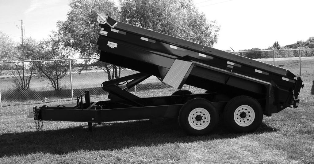
5 Knowing Your Trailer Stock Trailer 1) Your stock trailer has a high grade automotive finish on the outside and epoxy coating on the inside. Just like your vehicle it must be washed and maintained to keep it looking new. Wash trailer frequently with soap and water to rid trailer of salt and other debris. If pressure washer is to be used, hold it away from paint. Try not to use direct pressure as some washers have a tremendous amount of PSI which is hard on paint finishes. Waxing the exterior will help in the prevention of oxidation and keep your trailer looking like new. Try and clean the inside of your trailer as often as possible. Use a plastic shovel rather than steel, as plastic will not scrape the paint off the sides. If mats are used, try and pull them out frequently to avoid manure build up against walls. 2) Your trailer is equipped with grease fittings on side and rear doors. Grease regularly to avoid hinges from seizing. This should be done at least a couple of times a year. The rear door has two spring pin closures on the left and a spring lever on the lower middle. The three levers will help hold the door closed in three points to avoid bending. The center closure will prevent slide door from opening and is lockable. The left lower closure has a safety feature in that if livestock were to kick the rear door the catch on the closure will stop the door from hitting you. The slider door can also be opened from the inside of the trailer by pushing down on the lever in the right corner. 3
6 3) There is an oiling hole located on the top of the jack handle shaft. A couple drops of oil will help ease shaft movement. 4) The neck is adjustable and should be checked frequently to ensure it is tight. There is an adjuster bolt on the rear of the neck to snug the tube tight so as not to move. 5) The center gate has a locking lever on the outside of the trailer. When moved to the left placing it under the locking tab the gate cannot be opened from the inside of the trailer. When moved to the right the lever can be pulled from the outside to release the gate. This eliminates the need to go in the trailer. 6) Your wheels must be checked and re torque after first 10 miles, 25 miles and at 50 miles. Check periodically thereafter. See (Torque chart p.19) 7) Every trailer equipped with electric brakes will have a Breakaway System installed. The battery is mounted inside the neck and the breakaway switch is located beside the coupler. The breakaway switch is a safety feature designed to power the magnets and apply braking force in the event the trailer becomes disconnected. In order for this to happen the battery must be charged and maintained. See (Breakaway System p.20) 8) Brakes and bearing preload should be adjusted after the first 200 miles. See (Brake adjustment p.13) It is good practice to inspect and clean your trailer brakes at yearly intervals or more often as use and performance requires. 4
7 9) All Norbert trailers are equipped with greaseable hubs on 7000 lb. axles and under. You must maintain grease in the axle by pumping grease into the zerk located on the outside of the hub by way of a grease gun. There is a relief hole on the backside of the spindle so you cannot overfill. Axles larger than 7000 lb. are filled with oil. Levels can be checked by viewing through the glass caps on the outside of the hub. Oil must be level with the filling site on the glass. If oil is to be added it can be filled by removing the black rubber plug on the outside of the glass cap or the one located on the side of the hub. See (p.12) For proper wheel bearing lubrication. It is a good idea to check condition of bearings once a year to see if they need repacking, fresh oil or replacement. 5
8 Flat Deck Trailer 1) Your flat deck trailer has an industrial finish on the exterior. Just like your vehicle it must be washed and maintained to keep it looking like new. Wash trailer frequently with soap and water to rid trailer of salt and other debris. If pressure washer is to be used, hold it away from paint. Try not to use direct pressure as some washers have a tremendous amount of PSI which is hard on paint finishes. Waxing the exterior will help in the prevention of oxidation and keep your trailer looking like new. 2) Flat decks equipped with beavertails have four grease fittings. Two are located on the bottom side of the center drop at the hinge. The other two are located at the hinge of the fold down gate that holds up the center drop. Grease regularly to avoid hinges from seizing. The beavertail ramps are spring loaded to assist in the lifting of the ramps. There is an over center latch located on the underside of each ramp. These latches hold the ramps down to avoid being flipped over and dragged down the highway. Both ramps are adjustable inwards so smaller equipment can be loaded. 3) There is an oiling hole located on the top of the jack handle shaft. A couple drops of oil will help ease shaft movement. 4) The neck is adjustable and should be checked frequently to ensure it is tight. There is an adjuster bolt on the rear of the neck to snug the tube tight so as not to move. 5) Your wheels must be checked and re torqued after the 6
9 first 10 miles, 25 miles and at 50 miles. Check periodically thereafter. (Torque chart p.19) 6) Every trailer equipped with electric brakes will have a Breakaway System installed. The battery is mounted underneath the neck and the breakaway switch is located beside the coupler. The breakaway switch is a safety feature designed to power the magnets and apply force in the event the trailer becomes disconnected. In order for this to happen the battery must be charged and maintained. See (Breakaway System p.20) 7) Brakes and bearing preload should be adjusted after the first 200 miles. See (Brake adjustment p.13) It is good practice to inspect and clean your trailer brakes at yearly intervals or more often as use and performance requires. 8) Norbert trailers are equipped with greaseable axles on all axles up to 7000 lb. These axles are equipped with a grease zerk. You must maintain grease in the axle by pumping grease into the zerk by way of a grease gun. There is a grease hole on the backside of the spindle so you cannot overfill. Axles larger than 7000 lb. are filled with oil. Levels can be checked by viewing through the glass caps on the outside of the hub. Oil must be level with the filling site on the glass. If oil is to be added it can be filled by removing the black rubber plug on the outside of the glass cap or the one located on the hub. See (p.12) For proper wheel bearing lubrication. It is a good idea to check condition of bearings once a year to see if they need repacking, fresh oil or replacement. 7
10 Recommended Usage of Sure-Lube System Usage of the Sure-Lube system will not eliminate the need for general maintenance and inspection of the hub/drum components. However, will aid in the savings of time and effort. Recommended maintenance of this system is to insert Lithium base wheel bearing grease through the Zerk fitting provided in the end of the dust cap until it flows freely from the vent hole located in the rear of the spindle. The above procedure should be followed at regularly scheduled intervals; such as oil changes or chassis lubrications with usage and climactic conditions in mind. It is strongly urged that bearing components be inspected every 12,000 miles or annually to insure that no abnormal wear or bearing setting has resulted. 8
11 The Power of Protection When it comes to protection, nothing beats the patented power of Sure Lube. There s no springs. Or rubber plugs. Or O-rings. Sure Lube uses a revolutionary double lip springloaded seal that ensures outer/inner bearing protection from corrosion, wear and water entry. It s a time-saver, too. Sure Lube lets you grease or re-pack bearings with just a grease gun without disassembly. Sure Lube. When only the best will do. 9
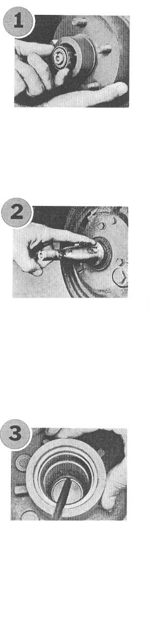


12 Bearing Maintenance Guide 10

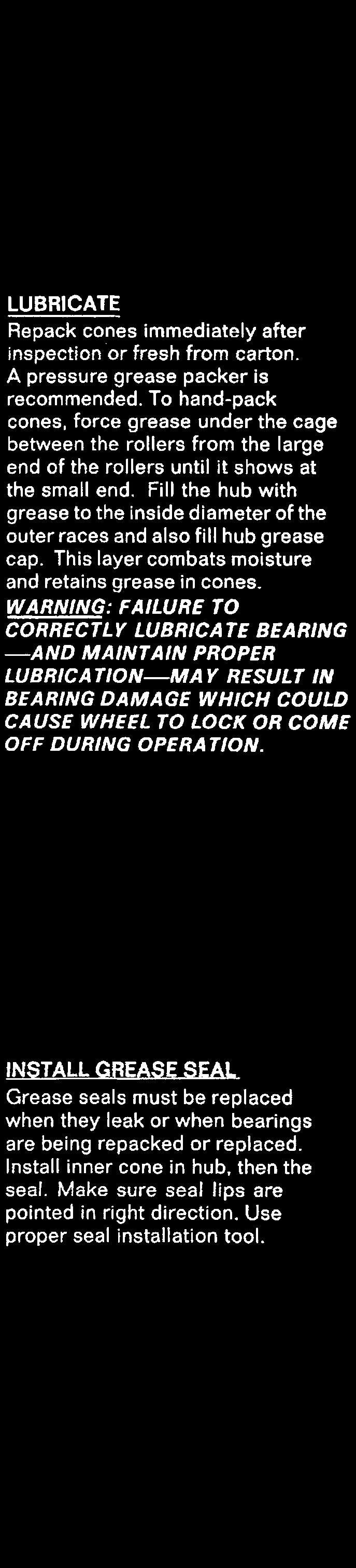

13 11
14 Recommended Wheel Bearing Lubrication Specifications Grease: Thickener Type Lithium Complex Dropping Point C (446 F) minimum Consistency NLGI No. 2 Additives... EP, Corrosion & Oxidation Inhibitors Base Oil Solvent Refined Petroleum Oil Base Oil C(104 F) 150cSt (695 SUS) Min. Viscosity Index Minimum Pour Point C(14 F) Minimum Oil: SAE 90 Hypoid Gear Oil (Hypoid Rear Axle Oil) Use only with hubs equipped with oil option Hydraulic Brake System Lubrication All hydraulic brake systems be it Surge, Electric/Hydraulic, Vacuum/Hydraulic all require reservoirs to be filled with a D.O.T. 3 or D.O.T. 4 fluid. 12
15 GENERAL MAINTENANCE BRAKE ADJUSTMENT On trailers equipped with 8,000 15,000 lb. axles brakes are self adjusting. Brakes should be adjusted after the first 200 miles of operation when the brake shoes and drums have seated, and at 3000-mile intervals or as use requires. The brakes should be adjusted in the following matter. 1. Jack up trailer and secure on adequate capacity jack stands. Support trailer on rear bumper or trailer frame located just behind the rear axle. Never lift or support trailer on axles. Check that the wheel and drum rotate freely. 2. Remove the adjusting hole cover from the adjusting slot on the bottom of the brake backing plate. 3. With a screwdriver or standard adjusting tool, rotate the starwheel of the adjuster assembly to expand the brake shoes. Adjust the brake shoes out until the pressure of the linings against the drum makes the wheel very difficult to turn. 4. Then rotate the starwheel in the opposite direction until the wheel turns freely with a slight lining drag. 5. Replace the adjusting hole cover and lower the wheel to the ground 6. Repeat the above procedure on all brakes. 13
16 Brake Cleaning and Inspection Your trailer brakes must be inspected and serviced at yearly intervals or more often as use and performance requires. Magnets and shoes must be changed when they become worn or scored thereby preventing adequate vehicle braking. Clean the backing plate, magnet arm, magnet, and brake shoes. Make certain that all the parts removed or replaced in the same brake and drum assembly. Inspect the magnet arm for any loose or worn parts. Check shoe return springs, and adjuster springs for stretch or deformation and replace if required. Brake Lubrication Before reassembly, apply a light film of Lubriplate, anti-seize compound, or similar product on the brake anchor pin, adjuster threads, the actuating arm bushing and pin and the areas on the backing plate that are in contact with the brake shoes and magnet lever arm. Apply a light film of grease on the actuating block mounted on the actuating arm. Magnets Your electric brakes are equipped with high quality electromagnets that are designed to provide the proper input force and friction characteristics. Your magnets should be inspected and replaced if worn unevenly or abnormally. As indicated below a straightedge should be used to check wear. 14
17 Even if wear is normal as indicated by your straightedge, the magnets should be replaced if any part of the magnet coil has become visible through the friction material facing of the magnet. It is also recommended that the drum armature surface be refaced when replacing magnets. Magnets should also be replaced in pairs both sides of an axle. Shoes and Linings A simple visual inspection of your brake linings will tell if they are usable. Replacement is necessary if the lining is worn (to within 1/16 or less), contaminated with grease or oil, or abnormally scored or gouged. Hairline heat cracks are normal in bonded linings and should not be a cause for concern. It is important to replace both shoes on each brake and both brakes of the same axle. This is necessary to retain the balance of your brakes A properly installed vacuum / hydraulic, air / hydraulic or electric hydraulic system should not require any special attention with the exception of routine maintenance such as shoe and lining replacement. If problems occur, the entire tow vehicle/ trailer braking system should be traced by a qualified 15
18 mechanic using a methodical approach to determine the exact source of the problem. Typical problems in a hydraulic braking system are: Air or Vacuum leaks Hydraulic system leaks Air in brake lines Water or other impurities in brake fluid Rusted or corroded master or wheel cylinders Most of the brake components are very similar to those used in electric brakes, and maintenance is comparable for the hub and drum, shoes and linings, and bearings. 16
19 Exploded View of a 7000 lb. Electric Brake Assembly 17
20 Exploded View of a 7000 lb. Hydraulic Brake Assembly 18
21 Torque Requirements Wheel nuts must be re torqued after the first 10 miles, 25 miles, and again at 50 miles. Check periodically thereafter. Wheel Torque Requirements 1/2 studs 95 ft. lbs. 9/16 studs 110 ft. lbs. 5/8 studs 200 ft. lbs. M ft. lbs. Torque Tightening Sequence 19
22 Breakaway System Your trailer is equipped with a breakaway switch. The switch is designed to operated only when the towed trailer separates from the towing vehicle. When this happens the lanyard cable pin is pulled out of the breakaway switch and the switch will close the circuit from the trailer battery to the brakes and put the brakes on. For the breakaway switch to operate properly it is important that the terminal connections are clean, the battery is fully charged and the switch is installed according to the following installation instructions. 1) There should be no obstacles or strain on the lanyard cable to the tow vehicle. The tow vehicle must be able to make sharp left and right turns without strain on the lanyard cable. 2) The lanyard cable should pull out before safety chains become fully extended. 3) Do not let lanyard cable dray on the ground. Fasten cable to the tow vehicle frame or hitch. Never hook on safety chains or tow ball. 4) Test the breakaway switch on a regular basis and make sure the lanyard cable is not damaged and the battery is fully charged. 5) When testing the switch disconnect trailer cord from tow vehicle. Pull lanyard pin out, this will take approximately 20 lbs. of pull. You should hear brakes engage. To double check, move tow vehicle forward to make sure brakes are locked and operating properly. 20
23 6) When test is complete make sure lanyard pin is fully pushed back in. To maximize the life of the battery the following conditions should be met: 1) Avoid over or undercharge. This is the single worst enemy of lead-acid batteries. 2) Batteries should not be stored in a discharge state or at elevated ambient temperature. 3) Avoid exposing batteries to heat! Service life is shortened considerably at ambients above 30 celsius. 4) Due to the characteristics of this battery, after six to nine months of storage, the battery should be recharged. 5) Charge the battery at the proper rate. Current should be limited to less than 1.2 amps. Charge current above 1.2 amps will result in shortened service life. 6) Provide adequate air circulation when charging battery. Do not charge battery in any other container besides the battery box provided. 7) Do not place battery in close proximity to objects which can produce sparks or flames. 8) Do not expose battery case to organic solvents or adhesives. 9) Do not attempt to disassemble batteries. Contact with sulfuric acid may cause harm. 10) Do not throw batteries into fire; batteries so disposed may rupture or explode. 21
24 Battery Data 12 Volt Gel Cel Max Discharge Current = 40 amps Max Charge Current Must Be Limited to 1.2 Amps Under Normal Operating Conditions Service Life: 4 5 years in standby applications or charge/discharge cycles depending upon depth of discharge cycles depending upon depth of discharge and rate of charge. To only charge the breakaway battery when the vehicle is running, a battery isolator may be installed in the 12 volt supply line. 22
25 Service Load and Inflation Table PSI: ST r 15 single (c) (D) ST r 15 single (C) (D) LT r 16 single (C) (D) (E) (F) (G) dual (C) (D) (E) (F) (G) r 17.5 single (H) dual (H) r 22.5 single (G) 5510(H dual (G) 5070(H) **Letters in parenthesis denote load range for which BOLD FACE loads are minimum. ** 23
26 Note: Tire wear should be checked frequently because once a wear pattern becomes firmly established in a tire it is difficult to stop, even if the underlying cause is corrected. Tire Wear Diagnostic Chart Wear Pattern Cause Action Center Wear Over Inflation Adjust pressure to particular load per tire catalog Edge Wear Under Inflation Adjust pressure to particular load per tire catalog Side Wear Loss of camber or overloading Make sure load doesn t exceed axle rating. Align at alignment shop. Toe Wear Incorrect toe-in Align at alignment shop. Cupping Out-of-balance Check bearing adjustment and balance tires. Flat Spots Wheel lockup & tire skidding Avoid sudden stops when possible and adjust brakes. 24
27 Trip Preparation Checklist It is extremely critical to follow the steps on this checklist prior to starting a trip with your trailer. By doing so, you are assured that you are taking all the necessary precautions to extend the life of your suspension system. Be sure to allow yourself sufficient time to perform the maintenance required. 1. Check your maintenance schedule to ensure that all maintenance matters are current. Perform any neglected maintenance. 2. Check trailer hitch for signs of wear. Lubricate the hitch if necessary. 3. Make sure that the breakaway battery is charged and inspect safety chains. 4. Inspect the tow vehicle s towing hookup. 5. Load the trailer and adjust the tongue weight so that 8% - 10% of the load is on the tongue. 6. Ensure that you are not over loaded and are staying within the capacity rating of the trailer. 7. Inspect tires for wear and adjust tire pressure according to the tire manufacturer s recommendations. 8 Check wheel nut or bolt torque values. Adjust per the specifications in this manual. 9. Make sure that the brakes are adjusted and synchronized properly. 10. Check all suspension fasteners and retorque if necessary following the procedures outlined in this manual. 11. Check all light operation. Replace any faulty bulbs. 12. Check and adjust your tow vehicle s tow height to make sure that the trailer is being towed level. 25
28 Maintenance Schedule Item Function Required every Use 3 Months or 6 Months or 12 Months or 3000 Miles 6000 Miles Miles Brake Adjustment Adjust to proper operating clearance Brake Controller Inspect for correct amp. & modulation Brake Cylinders Inspect for leaks, sticking Brake Lines Inspect for cracks, kinks & leakage Brake Linings Inspect for wear or contamination Brake Magnets Inspect for wear & current draw Brakes Test that they are operational Breakaway System Check battery charge and switch operation Clean Trailer Wash with soap & water Flooring Condition Inspect for wear & breakage Grease Hubs Grease sure-lube system Hub/Drum Inspect for abnormal wear or scoring Lights Inspect for breakage Adjustable Neck Make sure securing devices are tight Seals Inspect for damage and leakage Tire Condition Inspect for cuts, wear, bulging, etc Tire Inflation Pressure Inflate to mfg's. specifications Trailer Body Inspect for cracking, damage, peeling etc Trailer Hinges Inspect for grease Wheel Bearings & Cups Inspect for corrosion or wear. Clean & repack Wheel Nuts & Bolts Tighten to specified torque values Wheels Inspect for cracks, dents or distortion 26
29 Trailer Plug Wiring Diagrams 6-Prong Plug *Back view of plugs* RV-Plug Semi-Plug 27
30 WARRANTY Effective: 01/12/10 This trailer is warranted to be free from defects in material and workmanship to the original equipment manufacturer for of period of two (2) years, one (1) year on paint, five (5) years on axles from date of purchase. Please see attached warranties on axles and paint. 1. THIS WARRANTY DOES NOT COVER a. Lights; b. Batteries; c. Tires; d. Loss of wheels once trailer has left Norbert s Mfg; e. Towing and freight charges to and from Norbert s Manufacturing Ltd. or a qualified repair shop; f. Damage to trailer caused by misuse or abuse for what trailer is intended for; g. Any damage whatsoever to vehicle caused by trailer; h. Any responsibility whatsoever for monetary or business losses incurred by trailer downtime. All warranty work must be performed at Norbert s Manufacturing Ltd. in Glenboro, Manitoba or this will cause warranty to be voided unless approved in writing by Norbert s Manufacturing Ltd. Any alterations to interior or exterior of trailer such as; welding, bolting, painting etc. without prior written authorization from Norbert s Manufacturing Ltd. will cause warranty to be voided. Norbert s Manufacturing will not be responsible for any consequential or incidental damages incurred as a result of any defect. THE LIMITED WARRANTY SET FORTH ABOVE IS IN LIEU OF ALL OTHER WARRANTIES, EXPRESSED OR IMPLIED, AND NORBERT S MANUFACTURING LTD. DISCLAIMS THE IMPLIED WARRANTIES OF MERCHANTABILITY AND FITNESS FOR A PARTICULAR PURPOSE. Norbert s Mfg ltd. Box 280, Glenboro, Manitoba ROK OXO 28
31 WARRANTY CLAIM PROCEDURE Effective: 01/12/10 1. No warranty claim will be processed until Service Request form is filled out in full. 2. Request forms can be received from your Norbert dealer where the trailer was originally purchased. 3. Completed request form can be mailed or faxed to Norbert s Mfg. Ltd. 4. a clear-labeled picture must accompany Request Form if a Norbert s Mfg. Ltd. Warranty personnel cannot view alleged defective part. 5. All returned parts must be sent prepaid to Norbert s Mfg. Ltd. (Freight charges will be refunded if part is found defective). 6. Any parts or service required immediately while waiting for warranty will be paid by customer up front and will only be refunded in part or whole when Warranty Part and Service Request form is received, reviewed and approved in writing. 7. In the event the trailer needs service work, Norbert s Mfg. Ltd. will give 14 days for the customer to receive 2 quotes after the request form has been approved in writing. The customer then has 30 days to repair the trailer unless otherwise stated after Norbert s Mfg. Ltd. has approved the quote in writing. 29
32 Paint Warranty Norbert s paint is covered by warranty for a period of one (1) year from the date of purchase. All warranty work must be performed at Norbert s Manufacturing Ltd. in Glenboro, Manitoba or this will cause warranty to be voided unless approved in writing by Norbert s Manufacturing Ltd. Conditions of Warranty Warranty 1. applies only to surfaces painted directly by Norbert s Manufacturing Ltd. 2. is only valid to the original owner of the trailer and is not transferable. 3. does not apply to any Covered Defect, which is directly the result of any negligence by the customer. Terms of Warranty Warranty 1. applies to the finished areas indicated above and covers the following defects, if they are prominent and extensive and were not apparent at the time the owner accepted the trailer. a. Cracking or checking: b. Hazing, chalking or fading leading to a severe loss of gloss; c. Peeling of the topcoat or any layers from the substrate. 2. Exclusions d. System failures due to pre-existing rust; e. Deterioration of the finish caused by waxes and detergents not intended for automotive use, acid rain, industrial fallout or other environmental effects; f. Scratches, abrasions or stone chips whether intentional or accidental; g. Damages caused by another collision. 30
33 31
34 32
35 33
36 34
37 35
38 36
39
40 Manufacturing Ltd. Box 280, Glenboro, Manitoba R0K 0X0 Phone: (204) Fax: (204) Leech Printing
TRAILER AXLE MAINTENANCE
 Purpose To maintain and extend the product life of the Trailer Axle product line. Safety Failure to follow the instructions provided in this manual may result in death, serious personal injury, severe
TRAILER OPERATOR S MANUAL
 TRAILER OPERATOR S MANUAL TRB-3500, 1.103-818.0 89174670-1 For technical assistance call the dealer nearest you consult our web page at www.hotsy.com 8.917-467.0 contents Introduction...4 Machine Safety...4
Electric Brakes. Braking Systems - Electric
 Electric Brakes The electric brakes on your trailer are similar to the drum brakes on your automobile. The basic difference is that your automotive brakes are actuated by hydraulic pressure while your
DISC AND ELECTRIC BRAKE MAINTENANCE
 Purpose To maintain and extend the product life of the Disc Brake and Electric Brake product lines. Safety Failure to follow the instructions provided in this manual may result in death, serious personal
TRAILER OWNER S MANUAL
 This manual is designed to provide information for you to understand, use, maintain and service your Triton trailer. Additional help and replacement parts are available through your local dealer. TRAILER
Electric Brakes. Braking Systems - Electric
 Electric Brakes The electric brakes on your trailer are similar to the drum brakes on your automobile. The basic difference is that your automotive brakes are actuated by hydraulic pressure while your
Introduction: Note. Warning. The total weight 01your trailer and cargo must not exceed the trailer's gross vehicle weight rating.
 Introduction: This manual was prepared to acquaint you with the safe operation and maintenance of your Prowler Utility Trailer. We urge you to review this publication carefully. It will help you enjoy
Heavy Duty Engine Cranes
 Heavy Duty Engine Cranes Operating Instructions & Parts Manual Model Number Atd-7484 Atd-7485 (Foldable Legs) Capacity 2 Ton 2 Ton Model Atd-7484 Model Atd-7485 Atd Tools Inc. 160 Enterprise Drive, Wentzville,
OPERATIONS MANUAL LEVER CHAIN HOIST
 OPERATIONS MANUAL LEVER CHAIN HOIST IMPORTANT SAFETY INFORMATION Please read, understand and follow all safety information contained in these instructions prior to the use of this hoist. Retain these instructions
CAUTION. Hydraulic Brakes. Braking Systems - Hydraulic
 Hydraulic Brakes Dexter offers several varieties of hydraulic trailer brakes. Your vehicle may be equipped with drum brakes or disc brakes. The hydraulic brakes on your trailer are much like those on your
Wheels. Wheels and Tires ! CAUTION. Wheel Selection
 Wheels Wheel Selection Wheels are a very important and critical component of your running gear system. When specifying or replacing your trailer wheels it is important that the wheels, tires, and axle
GORE TRAILER MANUFACTURING INCORPORATED 305 Gore Trailer Road Whiteville, North Carolina 28472
 (Revised September, 2005) GORE TRAILER MANUFACTURING INCORPORATED 305 Gore Trailer Road Whiteville, North Carolina 28472 WARRANTY TEN YEAR WARRANTY Subject to the requirements, exclusions and limitations
Part # Jeep Grand Cherokee/Wagoneer 4WD 3 Lift Now Manufactured with Chromolly Arms PRO COMP SUSPENSION. Suspension Systems that Work!
 PRO COMP SUSPENSION Suspension Systems that Work! Important: Vehicles equipped with light duty, double offset joint (rubber boot) front driveshafts must be replaced with splicer constant velocity (CV)
Installation Instructions and Service Manual
 Installation Instructions and Service Manual Model 80 Actuator* for Trailer Brakes 8,00 lbs Capacity Drum Brake Ready Disc Brake Ready US Patents: 6,37,2 and 8,342,9 *Model 80 - Manufactured after March
PN# Dodge RAM Cummins 2500/3500 4WD (Except PowerWagon) Steering Box Brace Kit PRO COMP SUSPENSION. Suspension Systems that Work!
 Steering Box Brace Kit PRO COMP SUSPENSION. Suspension Systems that Work!") 2360 Boswell Road Chula Vista, CA 91914 Phone 619.216.1444 Fax 619.216.1474 E-Mail tech@explorerprocomp.com PRO COMP SUSPENSION Suspension Systems that Work! PN# 61239 2003-2008 Dodge RAM Cummins 2500/3500
2360 Boswell Road Chula Vista, CA 91914 Phone 619.216.1444 Fax 619.216.1474 E-Mail tech@explorerprocomp.com PRO COMP SUSPENSION Suspension Systems that Work! PN# 61239 2003-2008 Dodge RAM Cummins 2500/3500
US208S Scooter / Power Chair Carrier Lift N Go 117 Mini Electric Lift Electric Tote & 130 Swing Away Installation Guide & Owners Manual
 7325 Douglas Rd. Lambertville, MI 48144 Phone: 1-800-541-3213 Fax: (734) 568-6705 www.wheelchaircarrier.com E-mail: admin@wheelchaircarrier.com US208S Scooter / Power Chair Carrier - 210 Lift N Go 117
USER SGUIDE. maintenance storageguide
 USER SGUIDE GUIDE USER S Axle and Axlemaintenance maintenance and storage storageguide guide TABLE OF CONTENTS User s guide Maintenance schedule Storage Preparing for storage... Inspection procedures for
Installation Instructions and Service Manual
 Installation Instructions and Service Manual Model 66 Actuator* for Trailer Brakes 6600 lbs Capacity Part #47210/86167 - Drum Brake Ready Part #47211/86165 - Disc Brake Ready *US Patent No. 6,375,211 MODEL
Fitting Instruction for EZI-GRIP Bike Rack
 Fitting Instruction for EZI-GRIP Bike Rack Congratulations on purchasing Ezi-Grip to carry your valued bicycles. We are sure you will get many years of enjoyable use from your Ezi-Grip Bike Rack. These
1000-lb Hydraulic Truck Crane
 1000-lb Hydraulic Truck Crane Owner s Manual WARNING: Read carefully and understand all ASSEMBLY AND OPERATION INSTRUCTIONS before operating. Failure to follow the safety rules and other basic safety precautions
TRAILER OPERATOR S MANUAL
 MODE D' EMPLOI Red Yellow 15 Green 25 White 40 OFF I ON PRENDER O APAGAR HOROMETRO / CHRONOMETRE BURNER QUEMADOR/BRULEUR RESET 130 95 165 200 235 OFF F 10-02033 270 300 TRAILER OPERATOR S MANUAL OPERATING
OWNER/OPERATOR MANUAL. Airmotor effective dia. in. 2.5
 MODELS 282050, 282716 & 283513 AIR OPERATED CHASSIS PUMP SERIES A OWNER/OPERATOR MANUAL SPECIFICATIONS Airmotor effective dia. in. 2.5 Airinlet Material outlet 1/4 NPTF 1/4 NPTF Liquid to Air Pressure
Air Actuated Hydraulic Bottle Jacks
 Air Actuated Hydraulic Bottle Jacks Operating Instructions & Parts Manual Model Number Atd-7412 Atd-7420 Capacity 12 Ton 20 Ton Atd Tools Inc. 160 Enterprise Drive, Wentzville MO 63385 Printed in China
Wheels. Wheels and Tires ! CAUTION. Wheel Selection
 Wheel Selection Wheels Wheels are very important and critical components of your running gear system. When specifying or replacing your trailer wheels it is important that the wheels, tires, and axle are
Technical Information
 Product Group: TRAILERS Model: ALL MODELS This bulletin is provided for technical reference and service related updates. If you have any questions, comments or do not wish to receive these e-mails, please
Before equipment use, please read this operation manual carefully. Serial Number: Date Purchased:
 Pushed & Geared Trolleys OPERATION MANUAL This operation manual is intended as an instruction manual for trained personnel who are in charge of installation, maintenance, repair etc. Before equipment use,
12-1/4 x 3-1/2 Electric Wheel Brake
 12-1/4 x 3-1/2 Electric Wheel Brake A-216 819-0244 Installation Instructions An Altra Industrial Motion Company Contents Dimensions.... 2 Technical Specifications.... 3 Installation Instructions General....
INSTRUCTION MANUAL 22K - Fifth Wheel Hitch
 You can take it with you. INSTRUCTION MANUAL 22K - Fifth Wheel Hitch Product No. 30033 DEALER/INSTALLER: (1) Provide this Manual to end user. (2) Physically demonstrate hitching and unhitching procedures
INSTALLATION INSTRUCTIONS
 INSTALLATION INSTRUCTION AND SERVICE MANUAL Actuator/Trailer Dealer - Please provide these instructions to the consumer. Consumer - Read and follow these instructions. Keep them with the trailer for future
INSTRUCTION MANUAL TITAN 16K - Fifth Wheel Hitch Plymouth MI
 You can take it with you. INSTRUCTION MANUAL TITAN 16K - Fifth Wheel Hitch Plymouth MI Product No. 30866 DEALER/INSTALLER: END USER: (1) Provide this Manual to end user. (2) Physically demonstrate hitching
OWNER S / OPERATOR S 1
 OWNER S / OPERATOR S 1 DURALITE TRAILERS, LLC Duralite Aluminum Livestock Trailer Introduction To our customer: This manual has been prepared to help you operate and maintain your new Duralite Trailer
CHEVY / GMC 1500HD / 2500HD 2WD 8 LUG 7 BASIC KIT
 85101 2000-2010 CHEVY / GMC 1500HD / 2500HD 2WD 8 LUG 7 BASIC KIT C8510-4 MAIN BOX KIT W/ HARDWARE 1) FRONT X MEMBER 1) REAR X MEMBER 2) TORSION BAR DROPS 1) LEFT BUMP STOP 1) RIGHT BUMP STOP 2) SWAY BAR
Instruction Manual 30K - Fifth Wheel Hitch Part Number 30054
 You can take it with you. ELKHART, IN., OAKVILLE, ONT. Instruction Manual 30K - Fifth Wheel Hitch Part Number 30054 DEALER/INSTALLER: (1) Provide this Manual to end user. (2) Physically demonstrate hitching
GM WD P/U 6-LUG, AND ½ TON SUV S (CLASSIC BODY) W/ TORSION BARS SUSPENSION LIFT KIT KIT# TM106
 W/ TORSION BARS SUSPENSION LIFT KIT KIT# TM106") GM 1500 4WD P/U 6-LUG, AND ½ TON SUV S (CLASSIC BODY) W/ TORSION BARS SUSPENSION LIFT KIT 1988 2011 KIT# TM106 Installation of a Trail Master suspension lift kit will change the vehicle s center of gravity
GM 1500 4WD P/U 6-LUG, AND ½ TON SUV S (CLASSIC BODY) W/ TORSION BARS SUSPENSION LIFT KIT 1988 2011 KIT# TM106 Installation of a Trail Master suspension lift kit will change the vehicle s center of gravity
PORTABLE Q-CATCH 86 SERIES CHUTE & ALLEY PRODUCT MANUAL arrowquip.com
 PORTABLE Q-CATCH 86 SERIES CHUTE & ALLEY PRODUCT MANUAL 1-877-275-6075 cs@arrowquip.com arrowquip.com CONTENTS Safety Precautions 1 Risk Assessment 2 Q-Catch 86 Series Head Gate Assembly 3 Operating the
Model 80 & 80E Actuator* for Trailer Brakes 8000 lbs Capacity Part #47206/ Drum Brake Ready Part #47208/ Disc Brake Ready
 Installation Instructions and Service Manual For Serial Numbers 6020 and above. Model 80 & 80E Actuator* for Trailer Brakes 8000 lbs Capacity Part #47206/47207 - Drum Brake Ready Part #47208/47209 - Disc
LESTRONIC II BATTERY CHARGER MODEL 19740
 *01679* LESTRONIC II BATTERY CHARGER MODEL 19740 PLEASE SAVE THESE IMPORTANT SAFETY AND OPERATING INSTRUCTIONS For correct operation of the equipment, it is important to read and be familiar with this
Lincoln Hoist. Web Hoist Operating Manual. Lincoln Hoist
 Lincoln Hoist Web Hoist Operating Manual Lincoln Hoist Mfg. by Lincoln Precision Machining Company 121 Creeper Hill Road, P.O. Box 458, North Grafton, MA 01536 USA Toll Free (888) 306-7222 Phone (774)
Auto-Locking Trailer Coupler
 Auto-Locking Trailer Coupler 7-Ton Capacity Owner s Manual WARNING: Read carefully and understand all ASSEMBLY AND OPERATION INSTRUCTIONS before operating. Failure to follow the safety rules and other
Low Profile Service Jack Jack Stand Combo
 Low Profile Service Jack Jack Stand Combo Jack Stands Low Profile Service Jack U.S. Patent No. 6,199,379! This is the safety alert symbol. It is used to alert you to potential personal injury hazards.
Baxley Trailer Company 3300 E. Cottonwood Rd. Dothan, Al (334) Fax (334)
 Fax (334)") Baxley Trailer Company 3300 E. Cottonwood Rd. Dothan, Al. 36301 (334) 794-2393 Fax (334) 671-1351 www.baxleycompanies.com Patents #5,988,402 #6,520,521 Patents Pending....... SB-001 Motorcycle Trailer
Baxley Trailer Company 3300 E. Cottonwood Rd. Dothan, Al. 36301 (334) 794-2393 Fax (334) 671-1351 www.baxleycompanies.com Patents #5,988,402 #6,520,521 Patents Pending....... SB-001 Motorcycle Trailer
Instruction Manual 15K - Fifth Wheel Hitch Part Number 6030 & 6031
 DEALER/INSTALLER: (1) Provide this Manual to end user. (2) Physically demonstrate hitching and unhitching procedures in this Manual to end user. (3) Have end user demonstrate that he/she understands procedures.
PORTABLE Q-CATCH 86 SERIES CHUTE, ALLEY & TUB PRODUCT MANUAL arrowquip.com
 PORTABLE Q-CATCH 86 SERIES CHUTE, ALLEY & TUB PRODUCT MANUAL 1-877-275-6075 cs@arrowquip.com arrowquip.com CONTENTS Safety Precautions 1 Risk Assessment 2 Q-Catch 86 Series Head Gate Assembly 3 Operating
LESTRONIC II BATTERY CHARGER BUILT-IN OR PORTABLE CHARGERS
 LESTRONIC II BATTERY CHARGER BUILT-IN OR PORTABLE CHARGERS PLEASE SAVE THESE IMPORTANT SAFETY AND OPERATING INSTRUCTIONS For correct operation of the equipment, it is important to read and be familiar
ROTARY BRUSH CUTTERS THE LEADER OF THE PACK OWNER/OPERATOR SAFETY & INSTRUCTION MANUAL
 72 M-AX ROTARY BRUSH CUTTERS THE LEADER OF THE PACK OWNER/OPERATOR SAFETY & INSTRUCTION MANUAL CONTENTS Page 1. Introduction..................................2 2. Safety Instructions...........................3-4
OWNER S GUIDE 8A DURALIFT II 13,200 LB. CAPACITY. Link Mfg. Ltd th St. N.E. Sioux Center, IA USA
 OWNER S GUIDE 8A000715 DURALIFT II 13,200 LB. CAPACITY Link Mfg. Ltd. 223 15th St. N.E. Sioux Center, IA USA 51250-2120 www.linkmfg.com QUESTIONS? CALL CUSTOMER SERVICE 1-800-222-6283 DEALER / INSTALLER:
Instruction set # 7068 Cognito Motorsports, Inc. Upper Control Arm Leveling Kit for GM 8-Lug #UCAK (Boxed Style)
") Cognito Motorsports, Inc. Upper Control Arm Leveling Kit for 2001-2010 GM 8-Lug #UCAK100010 (Boxed Style) Introduction - These control arms will not affect the height of the truck, the height is determined
Cognito Motorsports, Inc. Upper Control Arm Leveling Kit for 2001-2010 GM 8-Lug #UCAK100010 (Boxed Style) Introduction - These control arms will not affect the height of the truck, the height is determined
R20 - Fifth Wheel Hitch
 You can take it with you. INSTRUCTION MANUAL R20 - Fifth Wheel Hitch Plymouth MI Product No. 30867 DEALER/INSTALLER: END USER: (1) Provide this Manual to end user. (2) Physically demonstrate hitching and
Cognito Motorsports, Inc. Upper Control Arm Kit for 2011-Present GM 8-Lug #UCAK100051
 Cognito Motorsports, Inc. Upper Control Arm Kit for 2011-Present GM 8-Lug #UCAK100051 Introduction - Installation requires a qualified mechanic. - Read instructions carefully and study the pictures (if
TITAN 13 x 2½ BRAKES DUO-SERVO AND FREE BACKING
 INSTALLATION INSTRUCTION AND SERVICE MANUAL Actuator/Trailer Dealer - Please provide these instructions to the consumer. Consumer - Read and follow these instructions. Keep them with the trailer for future
INSTRUCTION MANUAL. with ILLUSTRATED PARTS LIST. for TRAILER AND ACCESSORIES. Part Number (10,000 Pound Capacity)
") TO-37 0079 0884 07586 INSTRUCTION MANUAL with ILLUSTRATED PARTS LIST for TRAILER AND ACCESSORIES Part Number 48388- (0,000 Pound Capacity) manufactured by HOBART BROTHERS COMPANY POWER SYSTEMS DIVISION
TO-37 0079 0884 07586 INSTRUCTION MANUAL with ILLUSTRATED PARTS LIST for TRAILER AND ACCESSORIES Part Number 48388- (0,000 Pound Capacity) manufactured by HOBART BROTHERS COMPANY POWER SYSTEMS DIVISION
Hydraulic Truck Jack
 Operating Instructions & Parts Manual Hydraulic Truck Jack Model Capacity 23221C 22 Ton 23222C (Low Profile) 22 Ton 23301 30 Ton Models 23221C & 23222C Model 23301! U.S. Patent No's. 5,341,723 & 5,94,912
APCO CRF-100A RUBBER FLAPPER SWING CHECK VALVES
 APCO CRF-100A RUBBER FLAPPER SWING CHECK VALVES Instruction D12043 June 2016 DeZURIK Instructions These instructions provide installation, operation and maintenance information for APCO CRF-100A Rubber
Air Actuated Hydraulic Treadle Pump
 Porto-Power Blackhawk Automotive is a licensed trademark Air Actuated Hydraulic Treadle Pump Operating Instructions & Parts Manual B65425 B65426 B65427 SFA Companies 2005 10939 N. Pomona Ave. Kansas City,
Ride Rite Warranty Evaluation Guide
 What s covered The Ride-Rite kits, components, and accessories are warranted against defects in workmanship and materials*. What s not covered This warranty does not cover service or labor charges, freight
JEEP CHEROKEE (XJ) 3 SPRING KIT TM w/ Rear Add-A-Leaf & TM w/ Rear Leaf Spring
 3 SPRING KIT TM w/ Rear Add-A-Leaf & TM w/ Rear Leaf Spring") 400 W. Artesia Blvd. Fax: (310) 747-3912 Compton, CA 90220 Ph: (877) 695-7812 www.trailmastersuspension.com JEEP CHEROKEE (XJ) 3 SPRING KIT 84-01 TM3730-40013 w/ Rear Add-A-Leaf & TM3730-40023 w/ Rear
400 W. Artesia Blvd. Fax: (310) 747-3912 Compton, CA 90220 Ph: (877) 695-7812 www.trailmastersuspension.com JEEP CHEROKEE (XJ) 3 SPRING KIT 84-01 TM3730-40013 w/ Rear Add-A-Leaf & TM3730-40023 w/ Rear
Long Chassis Hydraulic Service Jacks
 Model BH6011 Long Chassis Hydraulic Service Jacks Operating Instructions and Parts Manual Capacity 10 Ton Model BH6011 U.S. Patent No's. 5,946,912 5,341,723! This is the safety alert symbol. It is used
APCO CSV-1600 SURGE CHECK VALVE
 APCO CSV-1600 SURGE CHECK VALVE Instruction D12022 January 2013 Instructions These instructions provide installation, operation and maintenance information for APCO CSV-1600 Surge Check Valves. They are
Operating Instructions & Parts Manual. Air/Manual Hydraulic Bottle Jacks
 J18124-M1_032015 Operating Instructions & Parts Manual Air/Manual Hydraulic Bottle Jacks Model J18124 J18204 Capacity 12 Ton 20 Ton U.S. Patent Nos. 6,012,377-5,946,912! This is the safety alert symbol.
INSTALLATION INSTRUCTIONS
 INSTALLATION INSTRUCTIONS Thank you for purchasing ROLTECTM Electric Hopper Conversion. Agri-Cover, Inc. proudly manufactured this hardware using superior quality materials and workmanship. With proper
Model 66/660* Actuator for Trailer Brakes 6,600 lbs Capacity Drum Brake Ready or Disc Brake Ready US Patent No. 6,375,211
 Installation Instructions and Service Manual Model 66/660* Actuator for Trailer Brakes 6,600 lbs Capacity Drum Brake Ready or Disc Brake Ready US Patent No. 6,375,211 *Model 660 - Manufactured after March
Safety Sentry Electronic Breakaway Switch
 Safety Sentry Electronic Breakaway Switch P-616-WE 819-0454 Installation Instructions An Altra Industrial Motion Company Parts List Mounting hardware included with the Safety Sentry Breakaway Switch kit:
Model ET 5000W Operation and Service Manual
 Model ET 5000W Operation and Service Manual Patented 5/16 BALL Load Capacity: 5000 lbs The ET 5000W ESCALATE TRAILER offers ground level roll-on loading and roll-off unloading of equipment with non-tilting
CAUTION. Hydraulic Brakes. Braking Systems - Hydraulic
 Hydraulic Brakes The hydraulic brakes on your trailer are much like those on your automobile or light truck. The hydraulic fluid from a master cylinder or actuation system is used to actuate the wheel
THE MODEL 916/918 HYDRAULIC REAR TINE TILLER
 THE MODEL 916/918 HYDRAULIC REAR TINE TILLER CONGRATULATIONS! You are now the proud owner of the BARRETO Model 916/918 tiller. Please take a moment of your time to look over the following information.
Brake System H TX, H2.0TXS [B475]; H TX [B466] Safety Precautions Maintenance and Repair
![Brake System H TX, H2.0TXS [B475]; H TX [B466] Safety Precautions Maintenance and Repair](/thumbs/86/93834005.jpg "Brake System H TX, H2.0TXS [B475]; H TX [B466] Safety Precautions Maintenance and Repair") HMM180001 Brake System H1.5-1.8TX, H2.0TXS [B475]; H2.5-3.5TX [B466] Safety Precautions Maintenance and Repair When lifting parts or assemblies, make sure all slings, chains, or cables are correctly fastened,
HMM180001 Brake System H1.5-1.8TX, H2.0TXS [B475]; H2.5-3.5TX [B466] Safety Precautions Maintenance and Repair When lifting parts or assemblies, make sure all slings, chains, or cables are correctly fastened,
SuperTrac. Axle. Service & Maintenance. Manual
 SuperTrac Axle Service & Maintenance Manual Table of Contents Page Exploded Views Section 1: General Information General Warnings Description of Axle Models Identifications Section 2: Installation Axle
The VAULT Hybrid Lubrication System
 Owners Manual for The VAULT Hybrid Lubrication System NO SERVICE NEEDED FOR 5 YEARS SEALED BEARING SYSTEM DO NOT SERVICE WITHOUT AUTHORIZED SERVICE KIT AND REPLACEMENT VAULT OIL Patent No. 5,551,530 TRAILER
2000-lb Hand Winch Truck Crane
 2000-lb Hand Winch Truck Crane Owner s Manual WARNING: Read carefully and understand all ASSEMBLY AND OPERATION INSTRUCTIONS before operating. Failure to follow the safety rules and other basic safety
Hydraulic Transmission Jacks
 Hydraulic Transmission Jacks Operating Instructions & Parts Manual Model Number Atd-7435 Atd-7436 Atd-7437 Capacity 1100 Lb. 2000 Lb. 3000 Lb. Model Atd-7435 Model Atd-7436 Model Atd-7437 Atd Tools Inc.
Service Information for. DISC BRAKES Model db35
 Service Information for DISC BRAKES Model db35 TRAILERING WITH DISC BRAKES Disc brakes offer several advantages over drum brakes that you will appreciate. Disc brakes have improved resistance to fade on
4745 Drill OWNER'S MANUAL (06-08) #
 #") 4745 Drill OWNER'S MANUAL (06-08) # 605865 Identification Your CrustBuster drill is identified by a Serial Number and Model Number. Record these numbers in the spaces provided in this manual and refer
4745 Drill OWNER'S MANUAL (06-08) # 605865 Identification Your CrustBuster drill is identified by a Serial Number and Model Number. Record these numbers in the spaces provided in this manual and refer
Owner s/operator s Manual
 All Trailer Models Owner s/operator s Manual G Series Deckover Skid Steer Utility Dump THIS MANUAL MUST BE READ AND UNDERSTOOD BEFORE ANYONE USES THIS TRAILER! Manual# 990006 Revised 02/2008 YOU MUST FILL
PRO COMP SUSPENSION PART# F-150 ADD-A-LEAF KIT. Suspension Systems that Work!
 2360 Boswell Road Chula Vista, CA 91914 Phone 619.216.1444 Fax 619.216.1474 E-Mail tech@explorerprocomp.com PRO COMP SUSPENSION Suspension Systems that Work! PART# 13134 2004 F-150 ADD-A-LEAF KIT This
Hydraulic Wheel Dolly
 Hydraulic Wheel Dolly Operating Instructions & Parts Manual Model Number HW93765 Capacity 3/4 Ton Made in the U.S.A. This is the safety alert symbol. It is used to alert you to potential personal injury
EZ-R7 T-Plug. Universal 7-Pin Heavy Duty Plug For Vehicles equipped with 7-Way Trailer Connectors. Installation Instructions and Product Warranty
 EZ-R7 T-Plug Universal 7-Pin Heavy Duty Plug For Vehicles equipped with 7-Way Trailer Connectors Installation Instructions and Product Warranty Professional Installation Required Thank you for purchasing
2 Speed Hydraulic Hand Pump
 Porto-Power Blackhawk Automotive is a licensed trademark 2 Speed Hydraulic Hand Pump Operating Instructions & Parts Manual B65122 B65421 SFA Companies 10939 N. Pomona Ave. Kansas City, MO 64153 816-891-6390
Ice House Axle OEM INSTALLATION MANUAL
 Ice House xle OEM INSTLLTION MNUL TLE OF CONTENTS System Information 2 Resources Required 2 Installation 3-7 Maintenance Schedule 8 Notes 9 System Information This manual will detail the procedure for
LUBRICATION AND MAINTENANCE
 PL LUBRICATION AND MAINTENANCE 0-1 LUBRICATION AND MAINTENANCE CONTENTS GENERAL INFORMATION... 1 JUMP STARTING, TOWING AND HOISTING... 7 MAINTENANCE SCHEDULES... 3 GENERAL INFORMATION INDEX GENERAL INFORMATION
Fast Lift Service Jack, Low Profile
 Blackhawk Automotive is a Licensed Trade Mark Made by SFA Companies, Kansas City, MO Fast Lift Service Jack, Low Profile Operating Instructions & Parts Manual Model BH6023B Capacity 2 Ton! U.S. Patent
SPECIFICATIONS CONTENTS: Specifications Warning Information. Operating Instructions Preventative Maintenance Troubleshooting
 Model 3182 2,500 Lbs Power Train Table/Lift OWNER'S MANUAL CONTENTS: Page 1 Page 2-3 Page 3 Page 4 Page 5 Page 5 Page 6 Page 7 Page 8 Specifications Warning Information Setup Operating Instructions Preventative
JEEP WRANGLER 2 & 4 DOOR (JK) 2.5 SPACER KIT KIT# TM /TM
 2.5 SPACER KIT KIT# TM /TM") 400 W. Artesia Blvd. Fax: (310) 747-3912 Compton, CA 90220 Ph: (877) 695-7812 www.trailmastersuspension.com JEEP WRANGLER 2 & 4 DOOR (JK) 2.5 SPACER KIT 07-13 KIT# TM3325-40010/TM3325-40013 Installation
400 W. Artesia Blvd. Fax: (310) 747-3912 Compton, CA 90220 Ph: (877) 695-7812 www.trailmastersuspension.com JEEP WRANGLER 2 & 4 DOOR (JK) 2.5 SPACER KIT 07-13 KIT# TM3325-40010/TM3325-40013 Installation
MOVE ON TO THE REAR BAR INSTALLATION
 22410 STREET SWAY BAR SET 2001-UP LEXUS IS300 Thank you for your purchase from our line of Lexus parts. Please call us at (877) 4NO-ROLL if you have any questions regarding the service or installation
Section 2 - Vehicle Preparation Section 6 - Safety Lift Arm Operation. Section 8 - Troubleshooting
 Deluxe Electric Powerchair and Scooter Carrier Instructions for Part # ESC400 Congratulations on your new lift purchase. Powered mobility lifts are one of the easiest and most trouble-free ways to transport
Read this entire manual before operation begins.
 Read this entire manual before operation begins. Record below the following information which is located on the serial number data plate. Serial No. Model No. Date of Installation Contents Specifications.............
Low Profile Service Jack
 Low Profile Service Jack Model GMG29031 Capacity 3 Ton U.S. Patent No. 6,199,379! This is the safety alert symbol. It is used to alert you to potential personal injury hazards. Obey all safety messages
Hydraulic Transmission Jack, Telescopic
 Operating Instructions & Parts Manual Hydraulic Transmission Jack, Telescopic Model 4000 400 (Air Operated) Capacity 000 lbs. 000 lbs. Model 4000 Model 400 U.S. Patent No. 6,02,377! This is the safety
BX7322 Adventurer Tow Bar Operator Manual & Installation Instructions
 Please visit www.blueox.com for the latest version of these installation instructions. BX7322 Operator Manual & Installation Instructions Serial Number (5,000 lb) 2 Inch Coupler 292-1263 Rev J Page 1 of
TT-12 OWNERS MANUAL/PARTS LIST
 TOPLIFTER Tailgates By THIEMAN TT-12 OWNERS MANUAL/PARTS LIST SHOWN WITH OPTIONAL 2 PC. ALUMINUM PLATFORM! IMPORTANT! KEEP IN VEHICLE! PLEASE READ AND UNDERSTAND THE CONTENTS OF THIS MANUAL BEFORE OPERATING
2253 FRONT AND REAR SPORT SWAY BAR SET CHEVROLET B-BODY
 2253 FRONT AND REAR SPORT SWAY BAR SET 65-66 CHEVROLET B-BODY Thank you for your purchase from our line of classic Chevrolet B-body suspension parts. Please call us at (877) 4NO-ROLL if you have any questions
Operating Instructions & Parts Manual
 Aluminum / Steel Hybrid Service Jack Operating Instructions & Parts Manual Model 26017 26028 26033 Capacity 1.5 Ton 2.5 Ton 3 Ton! This is the safety alert symbol. It is used to alert you to potential
Hollywood Racks Assembly & installation instructions for models:
 Hollywood Racks Assembly & installation instructions for models: HR1400Y (4 bike), HR1450Y (2 bike), HR1475Y, 1450Y-E & 1455Y-E (E bikes) For use on 2 hitches only. Do not use a 1 ¼ -2 hitch adapter. Maximum
SPECIFICATIONS GENERAL SAFETY RULES PERSONAL SAFETY. Save This Manual TOOL USE AND CARE WORK AREA
 SPECIFICATIONS 2 Forged Safety Latch Hooks Cable extends to: 44 Drop forged steel hanging bracket Heavy duty 3/16 Steel Cable Pulling Capacity: 1200 LB. One piece double ratchet gear Save This Manual You
Installation Instructions and Service Manual
 Installation Instructions and Service Manual Model 700LP/750LP (Low Profile) Actuator* for Trailer Brakes 7,000/7,500 lbs. Capacity Drum Brake Ready/Disc Brake Ready *US Patent No. 6,375,211 MODEL 700LP/750LP
EZ Carrier 3. Owner s Manual. Keep instructions for future reference
 EZ Carrier vv Owner s Manual Keep instructions for future reference Introduction The EZ Carrier provides all the flexibility you may need to transport your mobility scooter. The features include: The capability
(R86049) WARNING: To reduce the risk of injury, the user must read and understand the operator s manual before using this product.
 WARNING: To reduce the risk of injury, the user must read and understand the operator s manual before using this product.") OPERATOR S MANUAL 12 VOLT LITHIUM-ION BATTERY CHARGER 140446001 (R86049) Your charger has been engineered and manufactured to our high standards for dependability, ease of operation, and operator safety.
OPERATOR S MANUAL 12 VOLT LITHIUM-ION BATTERY CHARGER 140446001 (R86049) Your charger has been engineered and manufactured to our high standards for dependability, ease of operation, and operator safety.
Installation Instructions
 Equipment Required: Fastener Kit: F Wrenches: 3/4, 15/16 Drill Bits: 1/4 Other Tools: Drill WARNING: Under no circumstances do we recommend exceeding the towing vehicle manufacturers recommended vehicle
INSTALLATION INSTRUCTIONS
 INSTALLATION INSTRUCTIONS WARNING: NEVER EXCEED YOUR VEHICLE MANUFACTURER'S RECOMMENDED TOWING CAPACITY PIN-STYLE TRUNNION BAR WEIGHT DISTRIBUTION KIT MAINTENANCE Keep the socket-mounted ends of the spring
3000-Lb. Vehicle Positioning Jacks. Owner s Manual
 3000-Lb. Vehicle Positioning Jacks Owner s Manual WARNING: Read carefully and understand all ASSEMBLY AND OPERATION INSTRUCTIONS before operating. Failure to follow the safety rules and other basic safety
INSTALLATION MANUAL 4 I.F.S. SUSPENSION CURR. CHEVY SUBURBAN / YUKON XL (WITH 5 LINK REAR END) PART # 14965
 PART # 14965") PART NUMBER : 14965 2000 CURR. SUBURBAN W/ REAR COIL SPRINGS 4 SUSPENSION SYSTEM WITH FRONT SPINDLES PARTS LIST: Part # Description Qty. C4I1SN-07 Passenger Side Differential Drop 1 C4I1SN-23 Driver Side
PART NUMBER : 14965 2000 CURR. SUBURBAN W/ REAR COIL SPRINGS 4 SUSPENSION SYSTEM WITH FRONT SPINDLES PARTS LIST: Part # Description Qty. C4I1SN-07 Passenger Side Differential Drop 1 C4I1SN-23 Driver Side