RAILTRAMTM Height Safety System. Operator s Manual
|
|
|
- Brooke Chandler
- 6 years ago
- Views:
Transcription

1 RAILTRAMTM Height Safety System Operator s Manual 1
2 Doc No: TR-20-0-M-001 Effective: 15 January 2006 CONTENTS Introduction 3 Customer Service 3 Important Safety Information 4 Description of Equipment 6 Fall Restraint and Fall Arrest 8 Pre-Use Check 9 Operating Instructions 11 Cleaning and Preventative Maintenance 15 Periodic Examination 16 Overhaul and Repair 16 Equipment Records 17 Inspection and Maintenance Intervals 18 Equipment Record Form 19 2
3 INTRODUCTION This Manual contains safety information and instructions for operating the RAILTRAM system. This Manual should be stored in an area where it is accessible to operators of the RAILTRAM system. Continued improvement and advancement of product design may have caused changes to your RAILTRAM system, which are not included in this Manual. Some photographs or illustrations in this Manual may show details or attachments that are different from your RAILTRAM system. Whenever a question arises regarding your RAILTRAM, or this Manual, please consult the Standfast website at for the latest available information. Further information on operating the RAILTRAM system is available in training material and courses. Further enquiry regarding these materials and courses should be directed to: hq@standfastcorp.com The Equipment Record and an Operators Manual must be supplied to the end user when the RAILTRAM or TRAM belt are sold, resold, rented, or otherwise made available for use. This is to ensure that the end user gets the necessary information for the safe use of the RAILTRAM system. CUSTOMER SERVICE Please contact the authorised RAILTRAM distributor in your area for enquiries regarding the operation, Periodic Examination, Overhaul and Repair of your RAILTRAM system. The distributor nearest you can be found by consulting 3
4 Important Safety Information General Do not operate or work on the RAILTRAM system unless you have read and understand the instructions and warnings in this Manual. Failure to follow the instructions or heed the warnings could result in injury or death. Improper operation, maintenance or repair of this product can be dangerous and could result in injury or death. No one should make any alterations or additions to the equipment. Any repair shall only be carried out in accordance with authorized procedures. The RAILTRAM shall not be used outside its limitations as described in this Manual, or for any purpose other than that for which it is intended. Safe Working at Heights The operation and maintenance of the RAILTRAM system must comply with the safety Legislation and Regulations of the jurisdiction in which it is used. Operators of the RAILTRAM system must be properly trained and competent. Further enquiry regarding training materials and courses should be directed to: The TRAM restraint belt must only be used when the RAILTRAM system is used as a total restraint system. The TRAM restraint belt must not be used if there is a risk of free fall. Total restraint means that there is no risk of fall as the user is prevented from reaching a fall edge. This is achieved through combination of anchor point and lanyard length. Pre-Use Check Operators must carry out a Pre-Use check of the equipment, as per the instructions in this Manual, to ensure that it is in a serviceable condition and operates correctly before it is used. It is essential for safety that equipment is withdrawn from use immediately should any doubt arise about its condition for safe use.
5 Periodic Examination Periodic Examination should be carried out at intervals of six months or less. Periodic Examinations are only to be conducted by a Competent Person for Periodic Examination and strictly in accordance with Periodic Examination procedures. Equipment Records of Periodic Examination must be maintained and available to the operator. Installation Anyone installing or maintaining the RAILTRAM system must read, understand and strictly adhere to the instructions and safety information in this manual and the RAILTRAM System Installation Manual. The installer must verify the adequacy of the mounting points (the points to which RAILTRAM is attached to the parent equipment) either by calculation or by carrying out a test in a sample of the mounting point material in compliance with the specifications of the appropriate Standards, as per the instructions in the RAILTRAM System Installation Manual. Safety Signs and Labels The RAILTRAM system is permanently marked or labelled to indicate its purpose, correct use, limitations and other relevant safety information aimed at reducing the incidence or misuse or misfitting of the equipment. The labels also contain a unique serial number and the date of manufacture. - A TRAM belt label is usually affixed to the front of the belt. - A RAILTRAM Installation label is affixed at or close to the RAILTRAM Installation. The RAILTRAM Installation label should be clearly visible to the user before the user is in a position where there is a risk of fall. Make sure that you can read all safety signs. Clean or replace these if you cannot read the words or see the illustrations. When cleaning the labels use a cloth, water and soap. Do not use solvents, gasoline, etc., to clean safety signs. The use of solvents, gasoline, etc., could loosen the adhesive and cause the sign to fall off. You must replace a safety sign or label if it is damaged, missing or cannot be read. If a label is attached to a part, and that part is replaced, make sure a new label is installed on the replaced part. 5

6 Description of Equipment The RAILTRAM System RAILTRAM System - The RAILTRAM System includes a RAILTRAM slider unit that moves along a rail (the RAILTRAM Installation), and a restraint harness attached by two lanyards. The RAILTRAM provides the operator an ideal system of mobility and restraint. The user is firmly attached to the unit at all times and cannot fall. The system consists of the RAILTRAM Installation and the TRAM belt. RAILTRAM Installation The RAILTRAM Installation is comprised of a rail and a slider mechanism. The rail is mounted to the parent equipment by four upright sections on pivot bases. The rail pivots towards the ladder at these points. The upright sections lock into the pivot bases to hold the rail securely in the lowered position when not in use, and in the raised position when the user needs a secure anchor point. The user connects to a slider mechanism that provides an anchor point for fall prevention, and rotates to a locked position to ensure that the user is secure in their position at any point along the rail when working. 6


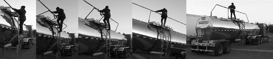
7 TRAM Belt The TRAM restraint body belt is an approved fall protection device that is designed for work positioning and restraint. The belt shown in this image is the style with a padded webbing back. The double action hooks are attached to the anchor point on the slider of the lowered rail. The user is demonstrating how the belt holds the user on the ladder if hand grip is lost. 7
8 Fall Restraint and Fall Arrest The RAILTRAM safety system is personal fall protection system. It is not suitable for fall arrest. Fall Restraint RAILTRAM is a restraint system. It is essential for safety that when RAILTRAM is used, a fall to a lower level is not possible. Note that: - The TRAM belt has two lanyards - The RAILTRAM slider has a single anchor points The operator should normally attach both lanyards to the anchor points, however the belt is rated to protect an operator if only one lanyard is attached. Operators should not anchor themselves with only one lanyard if doing so allows them to reach a position where a fall to a lower level is possible. The operator should ensure that all work tasks can be performed without restriction. Fall Arrest The RAILTRAM system is not a fall arrest device. 8
9 Pre-use Check Pre-Use checks are essential and should be carried out by the operator each time, before the RAILTRAM system is used. They consist of tactile and visual inspections to ensure the RAILTRAM system will be ready for immediate use. A visual check should be undertaken in good light. If during pre-use checks any of the following conditions are found, immediately withdraw the TRAM belt from service and pass it to a Competent Person (see definition the next page) who will determine what action to take: The belt has been inspected by a Competent Person within the last 6 months The TRAM belt label is not present or legible There is any doubt about the condition of the system for safe use TRAM belt Ensure that: There is an up-to-date Equipment Record for the TRAM belt There is a label on the belt, it is undamaged and can be read The serial number on the Equipment Record corresponds to the serial number on the belt label Before each use, the belt and lanyards should be checked for defects and damage have the potential to result in the failure of the belt, as follows: Cuts of 1 mm or more at the edges of webbing lanyards Surface abrasion across the face of the webbing, particularly if localised Abrasion at the edges, particularly if localised Damage to stitching (eg cuts or abrasion) A knot in the lanyard Chemical attack which can result in local weakening and softening often indicated by flaking of the surface. There may also be a change to the colour of the fibres Heat or friction damage indicated by fibres with a glazed appearance which may feel harder than surrounding fibres UV-degradation which is difficult to identify, particularly visually, but there may be some loss of colour (if dyed) and a powdery surface Contamination (eg with dirt, grit, sand etc) which may result in internal or external abrasion Damaged or deformed fittings (eg connectors) 9
10 RAILTRAM Installation The Operator may need to attach to the RAILTRAM safety system before completing all Pre-Use Checks as the RAILTRAM Installation are located where there is a risk of fall. Check the Equipment Record for the RAILTRAM Installation. Only check the RAILTRAM Installation labels when it is safe to do so, i.e. the operator may need to attach to the RAILTRAM safety system before checking the labels if there is a risk of fall. The Pre-Use Check of the RAILTRAM Installation consists of visual checks and checks of operation. Visually inspect the anchor point for signs of corrosion or deformation Attach to the lanyard hooks to the anchor point Depress the clutch levers and check that the RAILTRAM assembly is released and moves up freely After climbing from the ladder to the elevated work area, check that the locking pins seat correctly in the pivot bases. Check that the slider moves freely along the rail. Check the rail for damage, corrosion or deposits of foreign material that may affect the smooth operation of the RAILTRAM slider A Competent Person is defined as a person: who is knowledgeable of recommendations and instructions on the RAILTRAM System issued by Standfast (including information contained in this manual) who is authorised* by Standfast to carry out inspection, maintenance, servicing and repair work, who has the necessary training, skills and tools to perform the work properly, who is capable of identifying existing and predictable defects and hazards in any component of the RAILTRAM safety system and related equipment used in the work environment, who is authorised to take prompt corrective action to eliminate or control hazards, and has the skills and resources to do so, who is familiar with relevant guidelines and national and international safety regulations. *Your Standfast RAILTRAM Dealer is authorised to carry out all inspection, maintenance, servicing and repair work on the RAILTRAM System. Your Standfast RAILTRAM Dealer may also be contacted to authorise a Competent Person. 10


11 Operating Instructions STEP 1 PRE USE CHECK - Always check the system before use. See previous page. STEP 2 Place the TRAM restraint belt on. With the neoprene style belt (shown here) ensure that the Velcro strips are aligned and secured. STEP 3 Fasten the buckle. STEP 4 Pull the belt strap tight. Ensure that the double-action hooks are connected onto the belt in the carry position (as shown here) before climbing the ladder. 11


12 STEP 5 The double-action hooks are operated by first depressing the latch on the back spine of the hook and then opening the hook gate. STEP 6 Maintaining three points of contact Climb the ladder and stop at the lowest point on the ladder where the RAILTRAM rail can be reached and held. Unclip one hook from the carry position on the belt and attach it to the anchor point on the RAILTRAM slider. Repeat this for the other hook. Note: Do not cross the lanyards over when connecting them - connect the right-hand hook to right side of the anchor point, and the left-hand hook to left side of the anchor point. STEP 7 Hold the RAILTRAM rail with both hands, depress the clutch levers to allow the RAILTRAM to rise, then push up on the rail to raise it. Continue holding the rail with both hands whilst climbing the ladder onto the platform. 12


13 STEP 8 When reaching the platform, look to see that the locking pins in the upright sections have seated themselves in the pivot bases. If they are not properly seated, push or pull slightly on the top rail to align the locking pin with the slot in the pivot base. STEP 9 To move along the rail, hold the rail slider handle in the upright position whilst walking. When the desired work position is reached, rotate the slider towards you to lock it into position on the rail. To return along the platform towards the ladder, turn and hold the slider upright with the other hand. STEP 10 To descend from the walkway, turn to face the rail, depress the clutch levers and pull back on the rail. 13

14 STEP 11 Maintaining three points of contact Move from the walkway back on to the ladder, grasping the rail with both hands. One at a time, disconnect the lanyard hooks from the anchor point on the slider and reattach to the belt in the carry position Proceed back down the ladder. 14
15 Cleaning and Preventative Maintenance TRAM belt Cleaning Procedure 1. Wipe off surface dirt with a damp cloth 2. Clean webbing and hardware with warm water and mild detergent 3. Rinse in warm water 4. Drip-dry in the shade Do not place Belt near direct heat or in direct sun to dry Do not store a wet or damp belt RAILTRAM Installation Cleaning Procedure The RAILTRAM is constructed predominately of Stainless Steel components and is very durable in normal operating conditions. Care should be taken not to contaminate parts of the RAILTRAM device by allowing it to come into contact with mild or carbon steel cleaning implements. NEVER use steel wool (wire wool) or steel wire brushes to clean stainless steel. They are usually made of carbon steel and any fragments left behind will rust onto the stainless steel surface. Using any kind of scourer that has previously been used on mild or carbon steel should be avoided for the same reason. 1. Remove covers from the RAILTRAM pivot bases (if fitted) and visually inspect the RAILTRAM system for evidence of contaminants eg dust, stones, mud, cement, grain dust etc that will foul the working parts of the RAILTRAM. 2. Hose down the RAILTRAM Installation to remove any excess contaminants. 3. Visually inspect the Installation again and remove any further contaminates with the aid of brushes and cleaning tools. For best results, use mild detergent and warm water followed by rinsing with clean cold water. 4. If any stains or surface rust remains after the cleaning steps above scrubbing may be required. Use a clean nylon scourer or a cloth with chalk-based cream cleaner. Alternatively it may be necessary to use a proprietary stainless steel cleaner. These are usually based on dangerous chemicals (such as phosphoric, oxalic or sulphamic acids) and must be handled with care according to the manufacturer's directions. After cleaning it is important to neutralize any acids with a 1% ammonia or baking powder solution followed by rinsing with clean water. Cement and mortar splashes should be washed off before they set. Mild acids such as vinegar may be used, however avoid those using chloride rich chemicals. Do not use brick cleaning liquids that contain hydrochloric acid. 15
16 Periodic Examination The continued efficiency and durability of the RAILTRAM system and the safety of the user depends on regular Periodic Examination. Periodic Examination is a more formal, in-depth inspection and should be carried out on all elements of the RAILTRAM system periodically at intervals of six months or less. Periodic Examination is only to be conducted by a Competent Person and strictly in accordance with Periodic Examination procedures. It is essential that the person carrying out any inspection is sufficiently independent and impartial to allow them to make objective decisions, and has appropriate and genuine authority to discard defective equipment. Periodic Examination should be recorded in the Equipment Record. A Competent Person for Periodic Examination is a person who is knowledgeable of the current Periodic Examination requirements, recommendations and instructions issued by Standfast applicable to the relevant component, subsystem or system. This person should be capable of identifying and assessing the significance of defects, should initiate the corrective action to be taken and should have the necessary skills and resources to do so. Overhaul and Repair Overhaul is when the major wear items on the RAILTRAM are replaced. Note that no overhaul or repair is performed on the TRAM belt. If the belt needs more than cleaning or preventative maintenance, it should be replaced. The intervals represent maintenance of a non-failed RAILTRAM. In other words, the RAILTRAM is being rebuilt with certain new parts replacing worn parts such as main bearings. The Equipment Record lists the components inspected, rebuilt, exchanged or replaced at overhaul. Incidental to the replacement of these relatively few parts is the complete inspection of all other parts that are visible during the Overhaul of the RAILTRAM. The Overhaul interval assumes that regular Periodic Examinations have been carefully followed. Some users may obtain significantly longer or shorter life than the chart recommends between Overhauls, but if the recommended intervals are followed, Overhauls will occur before actual failure, and the total cost of operation will be minimized. 16
17 If you experience a structural failure, which necessitates a repair, or consider that your RAILTRAM system may have been overloaded, contact Standfast for information regarding Repair. Standfast may authorize some repairs to be conducted by a Competent Person. The repair procedure shall be strictly in accordance with the instructions provided by Standfast. Equipment Records Documentation is a key element of a well-managed personal protective equipment program. Equipment Records should be maintained as proof of Inspection and Maintenance of the RAILTRAM system. All Orders, Invoices and Receipts should be kept with the Equipment Records. It is the responsibility of the user organization to enter onto the Equipment Record the details required. An example template is shown at the end of this manual. 17
18 Inspection and Maintenance Intervals Inspection and maintenance should always be performed at the designated intervals. Type of Inspection / Maintenance PRE USE CHECK CLEANING AND PREVENTATIVE MAINTENANCE PERIODIC EXAMINATION AND MAINTENANCE OVERHAUL AND RECERTIFICATION REPAIR Should be carried out by the operator each time, before the RAILTRAM system is used May be carried out at any time as required and should be carried out at regular frequent intervals as determined by operating conditions Should be carried out by a Competent Person on all elements of the RAILTRAM system periodically at intervals of six months or less, or more frequently if the RAILTRAM system is operating in extreme conditions Should be carried out on all elements of the RAILTRAM system periodically at intervals of 5 years or less, or more frequently if the RAILTRAM is operating in extreme conditions May be carried out at any time as required The operating environment of the RAILTRAM also governs the Inspection and Maintenance schedule. Under extremely severe corrosive liquid or abrasive dust exposures or for operation under extremes of temperature, more frequent Inspection and Maintenance may be necessary. Perform Inspections and Maintenance on items at multiples of the original Inspection and Maintenance Interval. Standfast or your RAILTRAM distributor can assist you in tailoring your Inspection and Maintenance Intervals to meet the needs of your operating environment. 18
19 Equipment Record - Example EQUIPMENT RECORD Type of Equipment (tick one) RAILTRAM Installation TRAM belt This component is to be removed from service on: Unless it has been recertified by a competent person in accordance with Standfast instructions Serial Number: Owner: Date of Manufacture: Name of Organisation: Date of Purchase: Address (stamp): Date first put into use: Equipment Service / Maintenance / Repair History Date Activity Periodic service Overhaul Service Repair Remarks, e.g: Defects noted Repairs carried out Name & signature of competent person Next service due 19

20 20
OPERATIONS MANUAL LEVER CHAIN HOIST
 OPERATIONS MANUAL LEVER CHAIN HOIST IMPORTANT SAFETY INFORMATION Please read, understand and follow all safety information contained in these instructions prior to the use of this hoist. Retain these instructions
TONNEAU COVER INSTALLATION INSTRUCTION. Toyota Hilux 407L
 TONNEAU COVER INSTALLATION INSTRUCTION Toyota Hilux 407L Piece Tonneau Cover Place these instructions in vehicle s glove box after installation is complete Care Instructions: Clean Tonneau Cover with a
INSTALLATION INSTRUCTIONS TOP MOUNT SINKS
 These instructions are for installing top mount stainless steel sinks. (CH365 and CH366 NOT included) Please read all instructions carefully before starting the installation. TABLE OF CONTENTS Preparation
SECTION 6 5 SERVICE PROCEDURES AND SPECIFICATIONS. Body
 SERVICE PROCEDURES AND SPECIFICATIONS Body SECTION 6 5 Specifications........................................... 208 Protecting your vehicle from corrosion...................... 209 Washing and waxing.....................................
Glazed Screens. Handling and care manual (Construction Phase) January Performance Door, Window & Panel Manufacturers
 January Performance Door, Window & Panel Manufacturers") Glazed Screens Handling and care manual (Construction Phase) January 2018 Head Office: Pacific Door Systems Ltd. 17 Meachen Street, Seaview, Lower Hutt P.O. Box 36065, Wellington Mail Centre Lower Hutt
Glazed Screens Handling and care manual (Construction Phase) January 2018 Head Office: Pacific Door Systems Ltd. 17 Meachen Street, Seaview, Lower Hutt P.O. Box 36065, Wellington Mail Centre Lower Hutt
INSTRUCTION MANUAL. Pacific Self-locking Beam Trolleys Pacific Adjustable Angle Clamps Pacific Top Girder Clamps
 INSTRUCTION MANUAL Pacific Self-locking Beam Trolleys Pacific Adjustable Angle Clamps Pacific Top Girder Clamps IMPORTANT Please read this instruction manual before using these products. This manual contains
Reliance Industries, LLC. Installation, Operation, Inspection and Maintenance Instructions for the Slider Traveling Beam Anchor Clamp
 Reliance Industries, LLC Installation, Operation, Inspection and Maintenance Instructions for the Slider Traveling Beam Anchor Clamp Model # 3096 Model # 3097 Model # 3104 Reliance Industries, LLC PO Box
INSTALLATION INSTRUCTIONS TOP MOUNT SINK CH366
 27688 Industrial Blvd, Hayward, CA 94545 Tel: (877) 329 6872 Fax: (510) 723 0099 dp@dawnusa.net These instructions are for installing top mount sink CH366. Please read all instructions carefully before
SECTION 6 5 SERVICE PROCEDURES AND SPECIFICATIONS. Body
 SECTION 6 5 SERVICE PROCEDURES AND SPECIFICATIONS Body Specifications 236 Protecting your vehicle from corrosion 237 Washing and waxing 238 Cleaning the interior 239 235 SPECIFICATIONS DIMENSIONS AND WEIGHT
INSTALLATION INSTRUCTIONS UNDERMOUNT SINKS
 Kitchen & Bath Products, Inc. 27688 Industrial Blvd, Hayward, CA 94545 1-877-329-6872 dp@dawnusa.net These instructions are for installing undermount sinks. Please read all instructions carefully before
Tri-Wheel Wheeled Walker
 Tri-Wheel Wheeled Walker Handle with lever brake Brake cable Handle height adjustment knob Removable basket and tray Large vinyl bag 8 inch (203 mm) wheels user guide Prior to use please read all instructions.
Letter to the Customer
 OWNER S MANUAL INTRODUCTION The following information is for general maintenance and operation of the Quattro collection. Contact your local dealer or Hussey Seating Company Customer Service for more detailed
ABSOLUTE EQUIPMENT PTY LTD
 Manual Hydraulic Toe Jack Model DTJ Series ABSOLUTE EQUIPMENT PTY LTD 2/186 Granite Street, GEEBUNG QLD 4034 Australia sales@absoluteequipment.com.au Phone: +61 7 3865 4006 Fax: +61 7 3102 6288 This is
Maintenance Adjustments
 4 Maintenance and Adjustments Chapter Contents Cleaning the Printer and Paper Handling Accessories..... 158 Cleaning the HP Digital Copier....................... 161 Cleaning ADF and Glass............................
BEAM CLAMP INSTRUCTION MANUAL
 BEAM CLAMP INSTRUCTION MANUAL Imported exclusively for the Global Lifting Group by Pacific Hoists Pty. Ltd. & Pacific Hoists Ltd. 2 SAFETY INSTRUCTIONS THE FOLLOWING SAFETY INSTRUCTIONS OUTLINE THE CARE
ABSOLUTE EQUIPMENT PTY LTD
 Manual Hydraulic Toe Jack Model DTJ Series ABSOLUTE EQUIPMENT PTY LTD 2/186 Granite Street, GEEBUNG QLD 4034 Australia sales@absoluteequipment.com.au Phone: +61 7 3865 4006 Fax: +61 7 3102 6288 This is
OPERATIONAL ADVICE WARNING: TO PREVENT SERIOUS INJURY, PLEASE READ AND UNDERSTAND ALL WARNINGS AND INSTRUCTIONS BEFORE USE.
 OPERATIONAL ADVICE WARNING: TO PREVENT SERIOUS INJURY, PLEASE READ AND UNDERSTAND ALL WARNINGS AND INSTRUCTIONS BEFORE USE. SAVE THIS MANUAL Keep this manual in a safe place for future reference. This
***Please follow instructions for ease of installation and correct fit.***
 RAMPAGE P R O D U C T S Installation Instructions Part number 1094XX Frameless Soft Top for Jeep Wrangler YJ 1992-1995 with Half Doors NOTE: Installation of the top in warm weather is optimal for ease
USER MANUAL Edition
 USER MANUAL Edition 2 2014 CONTENTS Safety guidelines Transportation Unfolding and folding Tilt in space operation Seat depth and pelvic support adjustment Footrest adjustment Fitting optional accessories
3PC TONNEAU COVER WITH SPORTS BAR INSTALLATION INSTRUCTIONS
 3PC TONNEAU COVER WITH SPORTS BAR INSTALLATION INSTRUCTIONS TC00d / Vehicle Description: NISSAN NAVARA D0 DUAL CAB 3-PIECE TONNEAU COVER PARTS LIST NO. PART NAME QTY. NO. PART NAME QTY. NO. PART NAME QTY.
Booster Car Seat User Guide
 Booster Car Seat User Guide For future use, STORE USER GUIDE in location on bottom of base. IS0133.E 2015 Artsana USA, Inc. If you have any problems with your Chicco Booster Seat, or any questions regarding
English. Fitting Instructions: Bonneville and Bonneville T100 A , A and A of 9. Parts Supplied:
 English Fitting Instructions: Bonneville and Bonneville T00 A958085, A958086 and A958087 Thank you for choosing this Triumph genuine accessory kit. This accessory kit is the product of Triumph's use of
Phoenix Buggy User Instructions
 Phoenix Buggy User Instructions Issued 1 st March 2015 Introduction Welcome to the Phoenix Buggy User Guide. The Phoenix Buggy has been designed to provide a robust, transportable mobility solution for
Installation Instructions. Ultimate Screen. English Version 2.3
 Installation Instructions Ultimate Screen English Version 2.3 REMARKS. This manual simply describes the rules governing use and installing of the Ultimate Screen Blind. For different versions we would
3PC TONNEAU COVER INSTALLATION INSTRUCTIONS. Ford Ranger/Mazda BT-50 (without bedliner)
") 3PC TONNEAU COVER INSTALLATION INSTRUCTIONS Ford Ranger/Mazda BT-50 (without bedliner) Care Instructions: Clean Tonneau Cover with a mild detergent and water solution. Do not use abrasive cleaners or solvents.
3PC TONNEAU COVER INSTALLATION INSTRUCTIONS Ford Ranger/Mazda BT-50 (without bedliner) Care Instructions: Clean Tonneau Cover with a mild detergent and water solution. Do not use abrasive cleaners or solvents.
SB2 TubBuddy Owners Manual. elimination through innovation
 SB2 TubBuddy Owners Manual elimination through innovation contents Exploded Parts... 3 Parts List... 4 Securing Clip Sizes... 4 TubBuddy Assembly... 5 TubBuddy Setup... 12 TubBuddy Operation... 17 Cleaning
Meinzer II TM. Testing Sieve Shaker
 Meinzer II TM Testing Sieve Shaker Operation & Set-up Manual Model: 18480100 CSC Scientific, Inc. 2799-C Merrilee Drive Fairfax, VA 22031 USA Telephone: (703) 876-4030 (800) 621-4778 Fax: 703-280-5142
VEGETABLE OIL DISPOSAL UNIT (MSDU) OPERATOR & SERVICE MANUAL
 OPERATOR & SERVICE MANUAL") VEGETABLE OIL DISPOSAL UNIT (MSDU) OPERATOR & SERVICE MANUAL MANUFACTURED BY P.O. BOX 51000 SHREVEPORT, LOUISIANA 71135-1000 PHONE 1-318-865-1711 1-800-24 FRYER This equipment chapter is to be inserted
VEGETABLE OIL DISPOSAL UNIT (MSDU) OPERATOR & SERVICE MANUAL MANUFACTURED BY P.O. BOX 51000 SHREVEPORT, LOUISIANA 71135-1000 PHONE 1-318-865-1711 1-800-24 FRYER This equipment chapter is to be inserted
Vehicle Care ! WARNING: CLEANING PRODUCTS CLEANING THE EXTERIOR
 Chapter 8! WARNING: Many liquids and other substances used in vehicles are poisonous and should never be consumed and must be kept away from open wounds. These substances include antifreeze, brake fluid,
Required Tools: Phillips screw driver to remove original soft top. Torx sockets are required to completely remove the original soft top hardware.
 RAMPAGE P R O D U C T S Installation Instructions Part number 1099XX, Frameless Soft Top for 2 door Jeep Wrangler JK 2007- NOTE: Installation of the top in warm weather is optimal for ease of installation.
XChange Seat Service and Maintenance Guide
 XChange Seat Service and Maintenance Guide Table Of Contents Page General Information... 1 Registration Information... 1 Seat Cushion Latch... 2 Lap Shoulder Belt Replacement... 2 Sliding Buckles Replacement...
Accessory Fitting Instructions
 Accessory Fitting Instructions Swinging Arm Bag Kit, Waxed Cotton, Olive Kit Number Models Affected A908 Bonneville Bobber, Bonneville Speedmaster from VIN 79 Swinging Arm Bag Kit, Waxed Cotton, Black
BOSS ZONE 1 GRP MOBILE WORKING TOWER INSPECTION PROCEDURE. Youngman Group Ltd Issue B Date 23/03/09 Page 1 of 8 Pages
 BOSS ZONE 1 GRP MOBILE WORKING TOWER INSPECTION PROCEDURE Youngman Group Ltd Issue B Date 23/03/09 Page 1 of 8 Pages INTRODUCTION This inspection procedure applies to BoSS Zone 1 GRP Mobile Working Towers
Read and understand this entire manual before allowing child to use this product! For assistance contact Razor. DO NOT RETuRN TO STORE.
 Monster kix and Zombie kix Scooters OWNER S MANUAL Read and understand this entire manual before allowing child to use this product! For assistance contact Razor. DO NOT RETuRN TO STORE. NOTE: Manual illustrations
SECTION 6 CORROSION PREVENTION AND APPEARANCE CARE. Corrosion prevention and appearance care
 CORROSION PREVENTION AND APPEARANCE CARE SECTION 6 Corrosion prevention and appearance care Protecting your Toyota from corrosion......................... 382 Washing and waxing your Toyota.............................
HST -LS Interlocking device (Translation of Original Manual)
") Installation and Operating Manual for Components HST -LS Interlocking device (Translation of Original Manual) HST-LS Ident.-No.: 10268 HST-LS Ident.-No.: 10269 HST-LS, pictured Ident-Nr. 10269 The image
Installation and Operating Manual for Components HST -LS Interlocking device (Translation of Original Manual) HST-LS Ident.-No.: 10268 HST-LS Ident.-No.: 10269 HST-LS, pictured Ident-Nr. 10269 The image
1PC TONNEAU COVER INSTALLATION INSTRUCTIONS. Ford Ranger (with bedliner)
") PC TONNEAU COVER INSTALLATION INSTRUCTIONS Ford Ranger (with bedliner) Care Instructions: Clean Tonneau Cover with a mild detergent and water solution. Do not use abrasive cleaners or solvents. Place these
PC TONNEAU COVER INSTALLATION INSTRUCTIONS Ford Ranger (with bedliner) Care Instructions: Clean Tonneau Cover with a mild detergent and water solution. Do not use abrasive cleaners or solvents. Place these
40 V LITHIUM-ION BATTERY ATTACH YOUR RECEIPT HERE AB13786C 1. kobalttools.com ITEM # /
 ITEM #0506882 / 0506883 40 V LITHIUM-ION BATTERY MODEL #KB 240-06 / KB 440-06 Français p. 7 Español p. 13 ATTACH YOUR RECEIPT HERE Serial Number Purchase Date AB13786C 1 PRODUCT SPECIFICATIONS Battery
1000-LB. MOTORCYCLE LIFT TABLE OWNER S MANUAL
 1000-LB. MOTORCYCLE LIFT TABLE OWNER S MANUAL WARNING: Read carefully and understand all ASSEMBLY AND OPERATION INSTRUCTIONS before operating. Failure to follow the safety rules and other basic safety
Viking Use/Installation Guide
 Viking Use/Installation Guide Viking Range Corporation 111 Front Street Greenwood, Mississippi 38930 USA (662) 455-1200 For product information, call 1-888-VIKING1 (845-4641) or visit the Viking Web site
Mighty Mack Wheeled Walker
 Mighty Mack Wheeled Walker Handle with lever brake Backrest Handle height adjustment knob Brake cable Extra wide padded seat Shopping basket Side brace 7 inch (180 mm) wheels user guide Prior to use please
KidWalk KidWalk II Dynamic Mobility System
 OWNER S MANUAL KidWalk KidWalk II Dynamic Mobility System Manufactured By Prime Engineering A Division of Axiom Industries, Inc. Supplier Info 70111KWOM 2 TABLE OF CONTENTS This owner s manual is organized
PE51 HURLEY 3 STATION METAL SWING SET OWNER'S MANUAL
 PE51 HURLEY 3 STATION METAL SWING SET OWNER'S MANUAL WARNING! The disassembled product may contain small parts which pose a choking hazard to children under 3. IMPORTANT: This product may contain sharp
ATV TRACK KIT. Operator s Manual Installation Instructions Service Instructions Replacement Parts List. Effective Date: October, 2012
 p/n 2258-642 ATV TRACK KIT Operator s Manual Installation Instructions Service Instructions Replacement Parts List Track Assembly Kits (p/n 1436-204) Mounting Assembly Kits (p/n 1436-205) 1436-815) Effective
TELESCOPIC LADDER MODEL NO: TL-2B / TL-3B
 TELESCOPIC LADDER MODEL NO: TL-2B / TL-3B PART NO: 3500240 / 3500242 OPERATION & MAINTENANCE INSTRUCTIONS ORIGINAL INSTRUCTIONS LS0918 - ISS 1 INTRODUCTION Thank you for purchasing this CLARKE telescopic
Lineman s Hoist. Operating, Maintenance & Parts Manual. Follow all instructions and warnings for LMST680-2
 Lineman s Hoist LMST0- Operating, Maintenance & Parts Manual Lineman s Hoist Follow all instructions and warnings for inspecting, maintaining and operating this hoist. The use of any hoist presents some
Accessory Fitting Instructions
 Accessory Fitting Instructions Expedition Aluminium Pannier Kit - Silver Kit Number A9500600 A9500800 Models Affected Tiger XR, Tiger XRT, Tiger XRX, Tiger XC, Tiger XCA, Tiger XCX, Tiger Explorer XR,
LAD-MM Series Mobile Ladder Stands Instruction Manual
 Rev..8.07 LAD-MM, MANUAL Vestil Manufacturing Corp. 999 North Wayne Street, P.O. Box 507, Angola, IN 46703 Telephone: (60) 665-7586 -or- Toll Free (800) 348-0868 Fax: (60) 665-339 Web: www.vestilmfg.com
Nimbo Lightweight Posterior Posture Walker
 Nimbo Lightweight Posterior Posture Walker Assembly & Operating Instructions with optional Forearm Platforms with optional Pelvic Stabiliser Please read these instructions carefully before assembling or
USER MANUAL. Your ZINGO DRIFTA 360 warranty must be registered online within 7 days of purchase.
 USER MANUAL Your ZINGO DRIFTA 360 warranty must be registered online within 7 days of purchase. To activate your warranty visit www.tevo.co.za and click the Register your warranty tab at the top of the
Operating Instructions & Parts Manual. Fuel Tank Adapter
 Operating Instructions & Parts Manual Fuel Tank Adapter Model Number 40080 Capacity 80 lb.! This is the safety alert symbol. It is used to alert you to potential personal injury hazards. Obey all safety
Petite Wheeled Walker
 Petite Wheeled Walker Handle with lever brake Brake cable Handle height adjustment knob Backrest Padded seat with concealed pouch Bag with shopping basket inside Side brace 6 inch (150 mm) wheels user
NEOGARD. Preventive Maintenance Manual
 NEOGARD Preventive Maintenance Manual NEOGARD Floor Coating Systems December 2014 Notes NEOGARD Floor Coating Systems are designed to be long lasting and provide years of trouble-free service. Good general
3000-Lb. Vehicle Positioning Jacks. Owner s Manual
 3000-Lb. Vehicle Positioning Jacks Owner s Manual WARNING: Read carefully and understand all ASSEMBLY AND OPERATION INSTRUCTIONS before operating. Failure to follow the safety rules and other basic safety
Installation, Operating and Maintenance Instructions Retractable Door / Art.-Nr.:
 Installation, Operating and Maintenance Instructions Retractable Door 06.2008 / Art.-Nr.: 1 818 024 ENGLISH CONTENTS PAGE 1 SAFETY REQUIREMENTS 3 1.1 Symbols and key words used 3 1.2 Designated use 3 1.3
Euro Lightweight Wheeled Walker
 Euro Lightweight Wheeled Walker Handle with lever brake Backrest Brake cable Handle height adjustment button Removable shopping bag 8 inch (200 mm) wheels Cane holder user guide Prior to use please read
INSTRUCTIONS XL-518. ISOFIX CAR SEAT (with top tether) Group 1,2,3
 Group 1,2,3") INSTRUCTIONS XL-518 ISOFIX CAR SEAT (with top tether) Group 1,2,3 INSTRUCTIONS: PLEASE READ CAREFULLY AND KEEP FOR FUTURE REFERENCE. YOUR CHILD S SAFETY MAY BE AFFECTED IF YOU DO NOT FOLLOW THESE INSTRUCTIONS.
INSTRUCTIONS XL-518 ISOFIX CAR SEAT (with top tether) Group 1,2,3 INSTRUCTIONS: PLEASE READ CAREFULLY AND KEEP FOR FUTURE REFERENCE. YOUR CHILD S SAFETY MAY BE AFFECTED IF YOU DO NOT FOLLOW THESE INSTRUCTIONS.
Dealer Stamp. Rollator (R6 and R8) Assembly & Operating Instructions
 Assembly & Operating Instructions") The manufacturer reserves the right to alter without notice any weights, measurements or other technical data shown in this manual. All figures, measurements and capacities shown in this manual are approximate
The manufacturer reserves the right to alter without notice any weights, measurements or other technical data shown in this manual. All figures, measurements and capacities shown in this manual are approximate
Authorised By: Health and Safety Committee TITLE : ELECTRICAL SAFETY GUIDELINES IN-STORE DISPLAYS
 Original Issue: May 2012 Document No.: SMS.10.2 Revision No.: v4 (May) 2014 Page: 1 of 11 Revision Date: June 2015 Authorised By: Health and Safety Committee TITLE : ELECTRICAL SAFETY GUIDELINES IN-STORE
Push Down Wheeled Walker
 Push Down Wheeled Walker Push down hand grip Handle height adjustment knob Backrest Padded seat with concealed pouch Side brace Bag with shopping basket inside Push down brake stopper 6 inch (150 mm) wheels
Tooling Assistance Center
 Safeguards are designed into this application equipment to protect operators and maintenance personnel from most hazards during equipment operation. However, certain safety precautions must be taken by
Daytona Car Seat. User Guide
 Daytona Car Seat User Guide IMPORTANT Please retain this User Guide for future reference. Conforms to ECE R44.03 Universal EXTREME HAZARD: Parents should not under any circumstances use this child restraint
Cleaning, Maintenance and Repair
 aluminium www.egaluminium.co.uk Cleaning, Maintenance and Repair Aluminium and PVC-U Windows, Doors and Architectural Products Windows - Doors - Bi-Folds - Roof Lanterns - Shop Fronts Tel: 01823 618181
Aluminium 4-Wheeled Rollator/ Occassional Transport Chair VP184 Range Usage and Maintenance Instructions
 Aluminium 4-Wheeled Rollator/ Occassional Transport Chair VP184 Range Usage and Maintenance Instructions This file is available to view and download as a PDF at www.aidapt.co.uk. Sight impaired customers
Cleaning & Maintenance. For Aluminium Products
 Cleaning & Maintenance For Contents Cleaning & Maintenance 3 Repair 4 Fabrication & Installation Stage 5 Organic Coated Aluminium 6 Replacement Of Broken Glass 7 Hardware Maintenance 7 Sash Window Maintenance
Kent Ladder Grating. Recommended For:
 Kent Ladder Kent Ladder Specify Specify: Kent Ladder KLG150; 150mm wide x 1000mm long x 25mm deep; Grade 316L Stainless Steel; See page 8 & 9 which shows how to create your own unique specification clause
Stop! Read This Important Information.
 Stop! Read This Important Information. Stop, Do Not Proceed, Read This This door replacement kit is designed for the replacement of doors on a Supertop ONLY! This door will not work on any other style
Marlin Bath Lift BLM-8200 WARNING! Read ALL instructions before using this product!
 Marlin Bath Lift BLM-8200 www.inspiredbydrive.com WARNING! Read ALL instructions before using this product! PRODUCT DESCRIPTIONS Your Marlin Bath Lift has been built to the highest standards of quality
Instruction Manual. Maximum Operating Pressure 700 bar
 Remote Hydraulic Cutter Model HC-120R Maximum Operating Pressure 700 bar ABSOLUTE EQUIPMENT PTY LTD 2/186 Granite Street, GEEBUNG QLD 4034 Australia sales@absoluteequipment.com.au Phone: +61 7 3865 4006
1st Generation K5 Blazer (1969 to 1972)
") 1st Generation K5 Blazer (1969 to 1972) Tools needed: 9/64 drill bit Tape measure Pencil Drill Wrenches Screwdrivers Contents: 2 - bedrails (2 pieces each) 2 - folding frame uprights 1 header bar 3 - cross-bows
1st Generation K5 Blazer (1969 to 1972) Tools needed: 9/64 drill bit Tape measure Pencil Drill Wrenches Screwdrivers Contents: 2 - bedrails (2 pieces each) 2 - folding frame uprights 1 header bar 3 - cross-bows
Booster Car Seat. User Guide. in location on bottom of base. IS0174E_ Artsana USA, Inc. 01/19
 Booster Car Seat User Guide For future use, STORE USER GUIDE in location on bottom of base. IS0174E_03 2019 Artsana USA, Inc. 01/19 www.chiccousa.com TABLE OF CONTENTS If you have any problems with your
Wheel Horse. 44 Snowthrower. for 5xi Lawn and Garden Tractors. Model No & Up. Operator s Manual
 FORM NO. 8 Rev A Wheel Horse Snowthrower for 5xi Lawn and Garden Tractors Model No. 7966 890050 & Up Operator s Manual IMPORTANT: Read this manual, and your tractor manual, carefully. They contain information
SINK SPECIFICATIONS. ELONGATED DOUBLE BOWL Undermount Model VGR3218BL NOMINAL DIMENSIONS FEATURED MODELVGR3218BL 9" BOWL DEPTH
 SINK SPECIFICATIONS ELONGATED DOUBLE BOWL Undermount Model VGR3218BL FEATURED MODELVGR3218BL 9" BOWL DEPTH FEATURES 18 gauge, stainless steel 304 Nickel - Bearing Content Long-lasting, easy-to-clean, satin
Operating instructions. Skyline Beam Clamp Bypass
 Operating instructions for Skyline Beam Clamp Bypass Model # 3091 Reliance Industries, LLC PO Box 140008 Denver, CO 80214 Ph. (800) 488-5751 Ph. (303) 424-8650 Fax (303) 424-8670 User Instructions 3091
GoFitTM. Booster Car Seat User Guide. in location on bottom of base. IS0147.2E Artsana USA, Inc.
 GoFitTM Booster Car Seat User Guide For future use, STORE USER GUIDE in location on bottom of base. IS047.2E 207 Artsana USA, Inc. www.chiccousa.com TABLE OF CONTENTS If you have any problems with your
500kg TELESCOPIC TRANSMISSION LIFTER
 Product Code: 2056T PRODUCT CODE: 2056T 500kg TELESCOPIC TRANSMISSION LIFTER Safe Working Capacity 500kg Base Dimension 540 x 570 mm Minimum Height 1175mm Maximum Height 1900mm Made in China to TQB Brands
PUSH BUTTON KEY CABINET
 PUSH BUTTON KEY CABINET Model 95689 INSTALLATION And Operation Instructions Due to continuing improvements, actual product may differ slightly from the product described herein. 3491 Mission Oaks Blvd.,
IMPORTANT NOTICE: INCLUDED COMPONENTS
 RAMPAGE P R O D U C T S Installation Instructions Part number 680XX Complete Top and Hardware for Jeep Wrangler YJ 1987-95 w/ Full Steel Doors And Cj7 (with modifications) IMPORTANT NOTICE: Carefully read
Columbia Car Seat. User Guide. IMPORTANT Please retain this User Guide for future reference. Conforms to ECE R44.03 Universal
 Columbia Car Seat User Guide Conforms to ECE R44.03 Universal IMPORTANT Please retain this User Guide for future reference EXTREME HAZARD: Parents should not under any circumstances use this child restraint
2 Hours. Skill Level. 1 - Easy
 Installation Instructions Window Kit for Trektop NX Vehicle Application: Jeep Wrangler Unlimited (JK) 4 Door 2007 Current Part Number: 58223 Installation Tips Before you begin installing your new Trektop
BEFORE YOU START. page 3 page 4 page 5 page 6 page 7 page 8. page 2 page 3
 CONTENTS BEFORE YOU START MASTER ASSEMBLY UNFOLDING YOUR CITYGLIDE FOLDING YOUR CITYGLIDE ADJUSTING YOUR FOLDING MECHANISM MAINTENANCE page 3 page 4 page 5 page 6 page 7 page 8 AN IMPORTANT MESSAGE TO
Installation Instructions Supertop NX
 Installation Instructions Supertop NX Vehicle Application: Jeep Wrangler JK 2 Door 2007 Current Part Number: 54722 www.bestop.com - We re here to help! Visit our web site and click on Ask a Question. Click
Heavy Duty Engine Cranes
 Heavy Duty Engine Cranes Operating Instructions & Parts Manual Model Number ATD-7484 ATD-7485 (Foldable Legs) Capacity 2 Ton 2 Ton Model ATD-7484 Model ATD-7485 WARNING: This product may contain chemicals,
Skill Level. 1 - Easy
 Installation Instructions Window Kit for Trektop NX Twill Vehicle Application: Jeep Wrangler TJ 1997 2006 Part Number: 58420 Installation Tips Before you begin installing your new Trektop NX, please read
Operator's Manual. Storage System. Ultrasound Probe Cabinet. Manufactured by:
 Storage System Ultrasound Probe Cabinet Operator's Manual Manufactured by: CIVCO Medical Solutions 102 First Street South Kalona, IA 52247 USA 319.248.6757 / 800.445.6741 WWW.CIVCO.COM Copyright 2018 All
Installation Instructions Trektop NX
 Installation Instructions Trektop NX Vehicle Application: Jeep Wrangler TJ 1997 2006 Part Number: 56820 www.bestop.com - We re here to help! Visit our web site and click on Ask a Question. Click here for
A3 Seats and Seat Belts
 7DEOHRI&RQWHQWV A3 Seats and Seat Belts A3 Seats and Seat Belts Table of Contents Table of Contents... 1 Safety... 1 Warnings and Cautions... 1 Introduction... 2 List of Figures... 1 Seats... 2 Driver's
INSTALLATION INSTRUCTIONS
 INSTALLATION INSTRUCTIONS Trans4mer Grille Guard/Winch Mount For 2007 Toyota Tundra Kit 76380 (Black) and 76381 (Stainless) Your safety, and the safety of others, is very important. To help you make informed
Translation of the Original operating instructions Lifting device Z 70 /...
 Translation of the Original operating instructions Lifting device Z 70 /... Content 1. Lifting device / Correct use according to regulations 2. Basic principles 3. General information 4. Special remarks
HAND CRIMP TOOL SPECIFICATION SHEET Order No (Replaces HTR1719C)
") HAND CRIMP TOOL SPECIFICATION SHEET Order No. 63811-3300 (Replaces 11-01-0008 HTR1719C) TYPE 2C SCOPE Terminal Wire Size Insulation Diameter Strip Length Series No. AWG mm² mm In. mm In. 1560 18-24 0.82-0.20
HAND CRIMP TOOL SPECIFICATION SHEET Order No. 63811-3300 (Replaces 11-01-0008 HTR1719C) TYPE 2C SCOPE Terminal Wire Size Insulation Diameter Strip Length Series No. AWG mm² mm In. mm In. 1560 18-24 0.82-0.20
Users Manual. Ultra Care May 2003 GLO Pub. No
 Users Manual Ultra Care 4000 May 2003 GLO Pub. No. 234-2117-01 Ultra Care 4000 Disclaimer This manual contains general instructions for the use, operation and care of this product. The instructions are
Replace-a-Top. Installation Instructions. 60th Anniversary Top INSTALLATION TIME SKILL LEVEL TOOLS. Vehicle Application:
 Installation Instructions Replace-a-Top 60th Anniversary Top Vehicle Application: Jeep Wrangler CJ5 1976 1983 Part Number: 51117 Fits the OEM bows and door frames. www.bestop.com - We re here to help!
Medial Thigh Support installation & user manual
 User Manual for all Spex Medial Thigh Supports (product code begins with 1162- ) Revision: Pommel20170320 S Medial Thigh Support installation & user manual User Name: Serial Number: IMPORTANT CONSUMER
Kent Slotted Grating
 Kent Slotted Grating Kent Slotted Grating Specify Specify: Kent Antislip Ladder Grating KALG150; 150mm wide x 1000mm long x 25mm deep; Unlocked; Grade 304L Stainless Steel; Description: This Slotted Grating
TABLE OF CONTENTS Safe Use Checklist Registration & Recal Assistance Warnings Base Features Carrier Features Securing Child In Carrier
 TABLE OF CONTENTS Safe Use Checklist...4 Registration & Recall...5 Assistance...5 Warnings...6 Base Features Base Overview... Storage Compartment...3 Recline Adjustment...3 LATCH Removal & Storage...4
INSTALLATION & OWNER S MANUAL
 Rev. C, p. 1 of 18 INSTALLATION & OWNER S MANUAL KUBOTA RTV 400 CAB (Not for use on RTV 500) These instructions are for installation of the complete cab as well as the modular components. DESCRIPTION:
Portable Ladder Safety
 Portable Ladder Safety Disclaimer This training material presents very important information. Your organization must do an evaluation of all exposures, applicable codes and regulations, and establish proper
Heavy Duty Engine Cranes
 Heavy Duty Engine Cranes Operating Instructions & Parts Manual Model Number Atd-7484 Atd-7485 (Foldable Legs) Capacity 2 Ton 2 Ton Model Atd-7484 Model Atd-7485 Atd Tools Inc. 160 Enterprise Drive, Wentzville,
Tandem User Instructions
 Tandem User Instructions Issued 1 st November 2014 Tandem Buggy We designed the tandem buggy to enable families who have a disabled child and another younger child to enjoy the freedom they deserve. The
HANDLING MANUAL FILTERS & PRESSURE TANKS
 HANDLING MANUAL FILTERS & Basic Operation / Maintenance / Warranty INDEX A - Basic Operations A.1- Lifting and Unload...3 - Horizontal Tanks and Filters...3 - Vertical Tanks and Filters...4 - Important