V20, VA / VG20, VA / VG35 Open-Center Control Valves. Mobile Hydraulic Valves. Bulletin HY /US
|
|
|
- Owen Hunter
- 6 years ago
- Views:
Transcription


1 V20, VA / VG20, VA / VG35 Open-Center Control Valves Mobile Hydraulic Valves Bulletin HY /US
2 Contents Open-Center Directional Control Valves General Valve Assembly Information...1 V20 Valves Inlets...2 Main Relief Valves...2 Work Sections...3 Work Port Reliefs...3 Outlets...4 Action Kits...4 Handles and Accessories...4 Stud Kits...5 VA20 and VG20 Valves Inlets and Main Relief Valves...6 Work Sections...7 Positioner Kits...8 Stud Kits...8 Outlets...9 VA and VG Work Port Relief...9 VA and VG20 Handle Assemblies...9 VA35 and VG35 Valves Inlets and Main Relief Valve...10 Work Sections Handle Assemblies...11 VA35 and VG35 Valves Outlets...12 Positioner Kits...12 Stud Kits...13 Plugs...13 Terms of Sale with Warranty Limitations...14 Safety Guide WARNING USER RESPONSIBILITY FAILURE OR IMPROPER SELECTION OR IMPROPER USE OF THE PRODUCTS DESCRIBED HEREIN OR RELATED ITEMS CAN CAUSE DEATH, PERSONAL INJURY AND PROPERTY DAMAGE. This document and other information from Parker-Hannifin Corporation, its subsidiaries and authorized distributors provide product or system options for further investigation by users having technical expertise. The user, through its own analysis and testing, is solely responsible for making the final selection of the system and components and assuring that all performance, endurance, maintenance, safety and warning requirements of the application are met. The user must analyze all aspects of the application, follow applicable industry standards, and follow the information concerning the product in the current product catalog and in any other materials provided from Parker or its subsidiaries or authorized distributors. To the extent that Parker or its subsidiaries or authorized distributors provide component or system options based upon data or specifications provided by the user, the user is responsible for determining that such data and specifications are suitable and sufficient for all applications and reasonably foreseeable uses of the components or systems. OFFER OF SALE The items described in this document are hereby offered for sale by Parker-Hannifin Corporation, its subsidiaries or its authorized distributors. This offer and its acceptance are governed by the provisions stated in the detailed Offer of Sale elsewhere in this document or available at SAFETY GUIDE For safety information, see Safety Guide SG HY at or call CParker. Copyright 2015 Parker Hannifin Corporation, All Rights Reserved Parker Hannifin Corporation

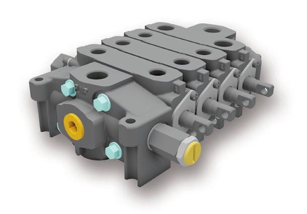
3 General Assembly Information Open-Center Directional Control Valves General Valve Assembly Information The Basics Every valve has the following elements: Inlet Main relief Work sections Outlet Section seals Stud kit to hold the assembly in place The valve inlet is connected directly to the outlet coming from the hydraulic pump, and the valve outlet is connected directly to the tank. The main relief valve is generally installed in the inlet and controls maximum system pressure. The valve work sections connect the cylinders, motors, spreader valves or other auxiliary valves. Work Section Types Sections can be the following types: Single Acting (one work port) Double Acting (two work ports) Actuators Work sections can be actuated by four means: Manual Handles Air Actuators Electric Solenoids Hydraulic Pilot Work Port Relief Valves Individual work section can have work port relief valves screwed into the sides of the work sections and can control: Control pressure Reduce cavitation Work port relief valves can be adjustable or fixed depending to the style. Work Sections Work Ports Locations for installing work port relief valves Combination Inlet / Outlet Handles Main Relief 1 Parker Hannifin Corporation


 2 Parker")
4 V20 Open-Center Directional Control Valves V20 Inlets Standard Mid Inlets Specifications Nominal Flow Operating Pressure Up to 95 LPM (25 GPM) Up to 240 Bar (3500 PSI) LC-12 Standard Inlet SAE SF Split Flow Mid Inlet SAE CF Combined Flow Mid Inlet SAE 12 V20 Main Relief Valves RP51A-3000 RP51A-3000 Main Relief Valve WH-1950 Fixed Main Relief Valve 134 Bar (1950 PSI) WH-2550 Fixed Main Relief Valve 176 Bar (2550 PSI) 2 Parker Hannifin Corporation


 08650388 CRA-1700")
5 V20 Open-Center Directional Control Valves V20 Work Sections Model V20 double-acting cylinder sections versus V20 motor spools cannot be visually determined simply by looking at the valves. It is important to keep the valves properly marked during the assembly process. It is recommended that a permanent M be marked on the motor spool so the installer will know the difference. 3-Way 3-Position 4-Way 3-Position Single-Acting Cylinder Spool SAE Double-Acting Cylinder Spool SAE F4 Double-Acting Motor Spool SAE PA1 Single-Acting Cylinder Spool Pneumatic SAE PA1 Double-Acting Cylinder Spool Pneumatic SAE 10 V20 Work Port Reliefs Anti-Cavitation Combination K-20-AC Anti-Cavitation Check CRA-1200 Combination PR/AC 83 Bar (1200 PSI) CRA-1700 Combination PR/AC 117 Bar (1700 PSI) CRA-1950 Combination PR/AC 134 Bar (1950 PSI) CRA-2500 Combination PR/AC 176 Bar (2550 PSI) 3 Parker Hannifin Corporation


6 V20 Open-Center Directional Control Valves V20 Outlets The Power Beyond Sleeve must be ordered separately and does not come installed. Standard Outlet Power Beyond Outlet Power Beyond Sleeve RC-12-E Standard Outlet SAE RC-12-E-MY Power Beyond Outlet SAE K Y Power Beyond Sleeve SAE K-20-X Conversion Plug SAE 12 Action Kits K-20-D 3-Position Detent K-20-PA1 Pneumatic Positioner Handles and Accessories K-20-VH-B Vertical Handle Black K-20-HH-B Horizontal Handle Black K-20-RET Standard Seal Retainer Plate Wiper Spool Wiper K-20-HBO-C1 Complete Bracket K-20-Boot Spool Boot Assembly 4 Parker Hannifin Corporation


7 V20 Open-Center Directional Control Valves Stud Kits Mid Inlets and Utility Sections count as a work section when selecting stud kits. Part Number Model Number Description K Work Section K Work Sections K Work Sections K Work Sections K Work Sections K Work Sections K Work Sections K Work Sections K Work Sections K Work Sections 5 Parker Hannifin Corporation
 347-9175-002 DVA20-A880 Inlet SAE 16 Porting 347-9174-004 DVA20-CFA70 Combined Flow Mid Inlet SAE 12 Porting 347-9174-002 DVA20-SFA70 Split Flow Mid Inlet SAE 12 Porting 391-1873-001")
8 VA20 and VG20 Open-Center Control Valves VA20 and VG20 Inlets / Main Relief Valves Specifications Nominal Flow Operating Pressure Up to 170 LPM (45 GPM) VA20 Up to 172 Bar (2500 PSI) VG20 Up to 241 Bar (3500 PSI) DVA20-A880 Inlet SAE 16 Porting DVA20-CFA70 Combined Flow Mid Inlet SAE 12 Porting DVA20-SFA70 Split Flow Mid Inlet SAE 12 Porting DVA20-MRV Adjustable Main Relief N/A DV20-MRVP Main Relief Plug N/A DVG20-A880 Inlet SAE 16 Porting DVG20-CFA70 Combined Flow Mid Inlet SAE 12 Porting DVG20-SFA70 Split Flow Mid Inlet SAE 12 Porting DVG20-HMRV Adjustable Main Relief N/A 6 Parker Hannifin Corporation

9 VA20 and VG20 Open-Center Control Valves VA20 and VG20 Work Sections Spring Return DVA20-DA7 Low Boy Double-Acting Cylinder Spool SAE DVA20-MA7 Low Boy Double-Acting Motor Spool SAE DVA20-SA7 Low Boy Single-Acting Cylinder Spool SAE DVA20-HA755 High Boy Double-Acting Cylinder Spool SAE DVA20-LA755 High Boy Double-Acting Motor Spool SAE DVA20-JA705 High Boy Single-Acting Cylinder Spool SAE DVG20-DA7 Low Boy Double-Acting Cylinder Spool SAE DVG20-MA7 Low Boy Double-Acting Motor Spool SAE DVG20-HA755 High Boy Double-Acting Cylinder Spool SAE DVG20-LA755 High Boy Double-Acting Motor Spool SAE DVG20-JA705 High Boy Single-Acting Cylinder Spool SAE 12 * Hi boy port accessories come standard unplugged and must use either a port option or port plug for operation. Pneumatic DVA20-DV7 Low Boy Double-Acting Cylinder Spool SAE DVA20-SV7 Low Boy Single-Acting Cylinder Spool SAE 12 7 Parker Hannifin Corporation


10 VA20 and VG20 Open-Center Control Valves VA20 and VG20 Positioner Kits DV20-K-113 Pneumatic Shifter DV20-K Position Detent DV20-K-100 Spring Center VA20 and VG20 Stud Kits Part Nmber Model Number Description DVA20-SK1 1 Work Section DVA20-SK2 2 Work Sections DVA20-SK3 3 Work Sections DVA20-SK4 4 Work Sedtions DVA20-SK5 5 Work Sections DVA20-SK6 6 Work Sections DVA20-SK7 7 Work Sections DVA20-SK8 8 Work Sections DVG20-TSK1 1 Work Section DVG20-TSK2 2 Work Sections DVG20-TSK3 3 Work Sections DVG20-TSK4 4 Work Sections DVG20-TSK5 5 Work Sections DVG20-TSK6 6 Work Sections DVG20-TSK7 7 Work Sections DVG20-TSK8 8 Work Sections TSK have studs and nuts 8 Parker Hannifin Corporation
 391-1873-008 DV-PRV-2 Work Port Relief 69-172 Bar")


11 VA and VG20 Open-Center Control Valves VA and VG Work Port Relief DV-PRVAC Screw Adjustable Work Port Relief DV-AC Anti-Cavitation Check Valve DV-PRV-1 Work Port Relief Bar ( PSI) DV-PRV-2 Work Port Relief Bar ( PSI) DV-PRV-3 Work Port Relief Bar ( PSI) DV-PRVP Work Port Relief Plug *PRV Accesories are shim adjustable. VA and VG20 Handle Assemblies DV20-H4 Standard 6" Handle DV20-H8 Standard 8" Handle VA20 and VG20 Outlets DVA20-TR88 Tank Return SAE DVA20-PB80 Power Beyond End Porting SAE DVA20-PB08 Power Beyond Top Porting SAE DVG20-TTR88 Tank Return SAE DVG20-TTB80 Power Beyond Porting SAE 16 9 Parker Hannifin Corporation
12 VA35 and VG35 Open-Center Control Valves VA35 and VG35 Inlets and Main Relief Valve Specifications Nominal Flow Up to 246 LPM (65 GPM) Operating Pressure VA35 Up to 172 Bar (2500 PSI) VG35 Up to 241 Bar (3500 PSI) DVA35-A880 Inlet SAE 16 Porting DVA35-CFA80 Combined Flow Mid Inlet SAE 16 Porting DVA35-SFA80 Split Flow Mid Inlet SAE 16 Porting DVA35-MRV-1 Main Relief Bar ( PSI) N/A DVA35-MRV-2 Main Relief Bar ( PSI) N/A DVG35-A880 Inlet SAE 16 Porting DVG35-CFA80 Combined Flow Mid Inlet SAE 16 Porting DVG35-SFA80 Split Flow Mid Inlet SAE 16 Porting DVG35-HMRV Main Relief Bar ( PSI) N/A VA35 and VG35 Work Sections Spring Return DVA35-DA8 Low Boy Double-Acting Cylinder Spool SAE DVA35-MA8 Low Boy Double-Acting Motor Spool SAE DVA35-SA8 Low Boy Single-Acting Cylinder Spool SAE DVA35-HA855 High Boy Double-Acting Cylinder Spool SAE DVA35-LA855 High Boy Double-Acting Motor Spool SAE DVA35-JA805 High Boy Single-Acting Cylinder Spool SAE Parker Hannifin Corporation
13 VA35 and VG35 Open-Center Control Valves VA35 and VG35 Work Sections Continued Spring Return DVG35-DA8 Low Boy Double-Acting Cylinder Spool SAE DVG35-MA8 Low Boy Double-Acting Motor Spool SAE DVG35-HA855 High Boy Double-Acting Cylinder Spool SAE DVG35-LA855 High Boy Double-Acting Motor Spool SAE DVG35-JA805 High Boy Single-Acting Cylinder Spool SAE 16 Pneumatic DVA35-DV8 Low Boy Double-Acting Cylinder Spool SAE DVA35-SV8 Low Boy Single-Acting Cylinder Spool SAE DVA35-HV855 High Boy Double-Acting Cylinder Spool SAE DVA35-LV855 High Boy Double-Acting Motor Spool SAE DVG35-HV855 High Boy Double-Acting Cylinder Spool SAE 16 * Hi boy port accessories come standard unplugged and must use either a port option or port plug for operation. VA35 and VG35 Handle Assemblies DV35-H4 Low Boy 6" Handle DV35-H8 High Boy 8" Handle 11 Parker Hannifin Corporation

14 VA35 and VG35 Open-Center Control Valves VA35 and VG35 Outlets DVA35-TR99 Tank Return SAE DVA35-PB90 Power Beyond SAE DVG35-TTR99 Tank Return SAE DVG35-TTB90 Power Beyond Porting SAE 20 VA35 and VG35 Positioner Kits DV35-K-213 Pneumatic Shifter DV35-K Position Detent DV35-K-200 Spring Center Detent 12 Parker Hannifin Corporation


15 VA35 and VG35 Stud Kits, Plugs VA35 and VG35 Stud Kits DVA35-SK1 1 Work Section DVA35-SK2 2 Work Sections DVA35-SK3 3 Work Sections DVA35-SK4 4 Work Sedtions DVA35-SK5 5 Work Sections DVA35-SK6 6 Work Sections DVA35-SK7 7 Work Sections DVA35-SK8 8 Work Sections DVG35-TSK1 1 Work Section DVG35-TSK2 2 Work Sections DVG35-TSK3 3 Work Sections DVG35-TSK4 4 Work Sections DVG35-TSK5 5 Work Sections DVG35-TSK6 6 Work Sections DVG35-TSK7 7 Work Sections DVG35-TSK8 8 Work Sections TSK have studs and nuts Plugs K-SAE-10 Plug 5/8" O-Ring K-SAE-12 Plug 3/4" O-Ring K-SAE-16 Plug 1" O-Ring DV-DPL-12 Plug 3/4" O-Ring DV-DPL-16 Plug 1" O-Ring DV-DPL-20 Plug 1 1/4" O-Ring 13 Parker Hannifin Corporation
16 Terms of Sale with Warranty Limitations Offer of Sale The goods, services or work (referred to as the Products ) offered by Parker-Hannifin Corporation, its subsidiaries, groups, divisions, and authorized distributors ( Seller ) are offered for sale at prices indicated in the offer, or as may be established by Seller. The offer to sell the Products and acceptance of Seller s offer by any customer ( Buyer ) is contingent upon, and will be governed by all of the terms and conditions contained in this Offer of Sale. Buyer s order for any Products specified in Buyer s purchase document or Seller s offer, proposal or quote ( Quote ) attached to the purchase order, when communicated to Seller verbally, or in writing, shall constitute acceptance of this offer. Conditions. Buyer s order for any item described in its document, when communicated to Seller verbally, or in writing, shall constitute acceptance of this offer. All goods or work described will be referred to as Products. 1. Terms and Conditions. Seller s willingness to offer Products for sale or accept an order for Products is subject to the terms and conditions contained in this Offer of Sale or any newer version of the same, published by Seller electronically at www. parker.com/saleterms/. Seller objects to any contrary or additional terms or conditions of Buyer s order or any other document or other communication issued by Buyer. 2. Price; Payment. Prices stated on Seller s Quote are valid for thirty (30) days, except as explicitly otherwise stated therein, and do not include any sales, use, or other taxes or duties unless specifically stated. Seller reserves the right to modify prices to adjust for any raw material price fluctuations. Unless otherwise specified by Seller, all prices are F.C.A. Seller s facility (INCOTERMS 2010). Payment is subject to credit approval and payment for all purchases is due thirty (30) days from the date of invoice (or such date as may be specified by Seller s Credit Department). Unpaid invoices beyond the specified payment date incur interest at the rate of 1.5% per month or the maximum allowable rate under applicable law. 3. Shipment; Delivery; Title and Risk of Loss. All delivery dates are approximate. Seller is not responsible for damages resulting from any delay. Regardless of the manner of shipment, delivery occurs and title and risk of loss or damage pass to Buyer, upon placement of the Products with the shipment carrier at Seller s facility. Unless otherwise stated, Seller may exercise its judgment in choosing the carrier and means of delivery. No deferment of shipment at Buyers request beyond the respective dates indicated will be made except on terms that will indemnify, defend and hold Seller harmless against all loss and additional expense. Buyer shall be responsible for any additional shipping charges incurred by Seller due to Buyer s acts or omissions. 4. Warranty. Seller warrants that the Products sold hereunder shall be free from defects in material or workmanship for a period of eighteen (18) months from the date of delivery. All prices are based upon the exclusive limited warranty stated above, and upon the following disclaimer: DISCLAIMER OF WARRANTY: THIS WARRANTY IS THE SOLE AND ENTIRE WARRANTY PERTAINING TO PRODUCTS PROVIDED. SELLER DISCLAIMS ALL OTHER WARRANTIES, EXPRESS AND IMPLIED, INCLUDING DESIGN, MERCHANTABILITY AND FITNESS FOR A PARTICULAR PURPOSE. 5. Claims; Commencement of Actions. Buyer shall promptly inspect all Products upon receipt. No claims for shortages will be allowed unless reported to the Seller within ten (10) days of delivery. No other claims against Seller will be allowed unless asserted in writing within thirty (30) days after delivery. Buyer shall notify Seller of any alleged breach of warranty within thirty (30) days after the date the defect is or should have been discovered by Buyer. Any claim or action against Seller based upon breach of contract or any other theory, including tort, negligence, or otherwise must be commenced within twelve (12) months from the date of the alleged breach or other alleged event, without regard to the date of discovery. 6. LIMITATION OF LIABILITY. IN THE EVENT OF A BREACH OF WARRANTY, SELLER WILL, AT ITS OPTION, REPAIR OR REPLACE A DEFECTIVE PRODUCT, OR REFUND THE PURCHASE PRICE WITHIN A REASONABLE PERIOD OF TIME. IN NO EVENT IS SELLER LIABLE FOR ANY SPECIAL, INDIRECT, INCIDENTAL OR CONSEQUENTIAL DAMAGES ARISING OUT OF, OR AS THE RESULT OF, THE SALE, DELIVERY, NON-DELIVERY, SERVICING, USE OR LOSS OF USE OF THE PRODUCTS OR ANY PART THEREOF, OR FOR ANY CHARGES OR EXPENSES OF ANY NATURE INCURRED WITHOUT SELLER S WRITTEN CON- SENT, WHETHER BASED IN CONTRACT, TORT OR OTHER LEGAL THEORY. IN NO EVENT SHALL SELLER S LIABILITY UNDER ANY CLAIM MADE BY BUYER EXCEED THE PURCHASE PRICE OF THE PRODUCTS. 7. User Responsibility. The user, through its own analysis and testing, is solely responsible for making the final selection of the system and Product and assuring that all performance, endurance, maintenance, safety and warning requirements of the application are met. The user must analyze all aspects of the application and follow applicable industry standards and Product information. If Seller provides Product or system options based upon data or specifications provided by the user, the user is responsible for determining that such data and specifications are suitable and sufficient for all applications and reasonably foreseeable uses of the Products or systems. 8. Loss to Buyer s Property. Any designs, tools, patterns, materials, drawings, confidential information or equipment furnished by Buyer or any other items which become Buyer s property, will be considered obsolete and may be destroyed by Seller after two (2) consecutive years have elapsed without Buyer ordering the items manufactured using such property. Seller shall not be responsible for any loss or damage to such property while it is in Seller s possession or control. 9. Special Tooling. A tooling charge may be imposed for any special tooling, including without limitation, dies, fixtures, molds and patterns, acquired to manufacture Products. Such special tooling shall be and remain Seller s property notwithstanding payment of any charges by Buyer. In no event will Buyer acquire any interest in apparatus belonging to Seller which is utilized in the manufacture of the Products, even if such apparatus has been specially converted or adapted for such manufacture and notwithstanding any charges paid by Buyer. Unless otherwise agreed, Seller has the right to alter, discard or otherwise dispose of any special tooling or other property in its sole discretion at any time. 10. Buyer s Obligation; Rights of Seller. To secure payment of all sums due or otherwise, Seller retains a security interest in all Products delivered to Buyer and this agreement is deemed to be a Security Agreement under the Uniform Commercial Code. Buyer authorizes Seller as its attorney to execute and file on Buyer s behalf all documents Seller deems necessary to perfect its security interest. 11. Improper Use and Indemnity. Buyer shall indemnify, defend, and hold Seller harmless from any losses, claims, liabilities, damages, lawsuits, judgments and costs (including attorney fees and defense costs), whether for personal injury, property damage, patent, trademark or copyright infringement or any other claim, brought by or incurred by Buyer, Buyer s employees, or any other person, arising out of: (a) improper selection, application, design, specification or other misuse of Products purchased by Buyer from Seller; (b) any act or omission, negligent or otherwise, of Buyer; (c) Seller s use of patterns, plans, drawings, or specifications furnished by Buyer to manufacture Products; or (d) Buyer s failure to comply with these terms and conditions. Seller shall not indemnify Buyer under any circumstance except as otherwise provided. 12. Cancellations and Changes. Buyer may not cancel or modify or cancel any order for any reason, except with Seller s written consent and upon terms that will indemnify, defend and hold Seller harmless against all direct, incidental and consequential loss or damage. Seller may change Product features, specifications, designs and availability. 13. Limitation on Assignment. Buyer may not assign its rights or obligations under this agreement without the prior written consent of Seller. 14. Force Majeure. Seller does not assume the risk and is not liable for delay or failure to perform any of Seller s obligations by reason of events or circumstances beyond its reasonable control (hereinafter Events of Force Majeure ). Events of Force Majeure shall include without limitation: accidents, strikes or labor disputes, acts of any government or government agency, acts of nature, delays or failures in delivery from carriers or suppliers, shortages of materials, or any other cause beyond Seller s reasonable control. 15. Waiver and Severability. Failure to enforce any provision of this agreement will not invalidate that provision; nor will any such failure prejudice Seller s right to enforce that provision in the future. Invalidation of any provision of this agreement by legislation or other rule of law shall not invalidate any other provision herein. The remaining provisions of this agreement will remain in full force and effect. 16. Termination. Seller may terminate this agreement for any reason and at any time by giving Buyer thirty (30) days prior written notice. Seller may immediately terminate this agreement, in writing, if Buyer: (a) breaches any provision of this agreement (b) appoints a trustee, receiver or custodian for all or any part of Buyer s property (c) files a petition for relief in bankruptcy on its own behalf, or one if filed by a third party (d) makes an assignment for the benefit of creditors; or (e) dissolves its business or liquidates all or a majority of its assets. 17. Governing Law. This agreement and the sale and delivery of all Products are deemed to have taken place in, and shall be governed and construed in accordance with, the laws of the State of Ohio, as applicable to contracts executed and wholly performed therein and without regard to conflicts of laws principles. Buyer irrevocably agrees and consents to the exclusive jurisdiction and venue of the courts of Cuyahoga County, Ohio with respect to any dispute, controversy or claim arising out of or relating to this agreement. 18. Indemnity for Infringement of Intellectual Property Rights. Seller is not liable for infringement of any patents, trademarks, copyrights, trade dress, trade secrets or similar rights except as provided in this Section. Seller will defend and indemnify Buyer against allegations of infringement of U.S. patents, U.S. trademarks, copyrights, trade dress and trade secrets ( Intellectual Property Rights ). Seller will defend at its expense and will pay the cost of any settlement or damages awarded in an action brought against Buyer based on an allegation that a Product sold pursuant to this agreement infringes the Intellectual Property Rights of a third party. Seller s obligation to defend and indemnify Buyer is contingent on Buyer notifying Seller within ten (10) days after Buyer becomes aware of such allegations of infringement, and Seller having sole control over the defense of any allegations or actions including all negotiations for settlement or compromise. If a Product is subject to a claim that it infringes the Intellectual Property Rights of a third party, Seller may, at its sole expense and option, procure for Buyer the right to continue using the Product, replace or modify the Product so as to make it noninfringing, or offer to accept return of the Product and refund the purchase price less a reasonable allowance for depreciation. Notwithstanding the foregoing, Seller is not liable for claims of infringement based on information provided by Buyer, or directed to Products delivered hereunder for which the designs are specified in whole or part by Buyer, or infringements resulting from the modification, combination or use in a system of any Product sold hereunder. The foregoing provisions of this Section constitute Seller s sole and exclusive liability and Buyer s sole and exclusive remedy for infringement of Intellectual Property Rights. 19. Entire Agreement. This agreement contains the entire agreement between the Buyer and Seller and constitutes the final, complete and exclusive expression of the terms of sale. All prior or contemporaneous written or oral agreements or negotiations with respect to the subject matter are herein merged. The terms contained herein may not be modified unless in writing and signed by an authorized representative of Seller. 20. Compliance with Laws. Buyer agrees to comply with all applicable laws, regulations, and industry and professional standards of care, including those of the United Kingdom, the United States of America, and the country or countries in which Buyer may operate, including without limitation the U. K. Bribery Act, the U.S. Foreign Corrupt Practices Act ( FCPA ), the U.S. Anti-Kickback Act ( Anti-Kickback Act ) and the U.S. Food Drug and Cosmetic Act ( FDCA ),each as currently amended, and the rules and regulations promulgated by the U.S. Food and Drug Administration ( FDA ), and agrees to indemnify and hold harmless Seller from the consequences of any violation of such provisions by Buyer, its employees or agents. Buyer acknowledges that it is familiar with the provisions of the U. K. Bribery Act, the FCPA, the FDA, and the Anti-Kickback Act, and certifies that Buyer will adhere to the requirements thereof. In particular, Buyer represents and agrees that Buyer will not make any payment or give anything of value, directly or indirectly to any governmental official, any foreign political party or official thereof, any candidate for foreign political office, or any commercial entity or person, for the purpose of influencing such person to purchase Products or otherwise benefit the business of Seller. 5/14 14 Parker Hannifin Corporation
17 Parker Safety Guide for Selecting and Using Hydraulic Valves and Related Accessories WARNING: Failure or improper selection or improper use of Parker (HVD) Valves or related accessories ( Products ) can cause death, personal injury and property damage. Possible consequences of failure or improper use of these Products include but are not limited to: Valves or parts thereof thrown off at high speed Contact with fluid that may be hot, cold, toxic or otherwise injurious High velocity fluid discharge Injuries resulting from injection, inhalation or exposure to fluids Explosion or burning of the conveyed fluid Injury from handling a heavy item (dropped, awkward lift) Contact with suddenly moving or falling objects controlled by the Valve Electric shock from improper handling of solenoid connections Injections by high-pressure fluid discharge Injury from slip or fall on spilled or leaked fluid Before selecting or using any of these Products, it is important that you read and follow the instructions below. In general, the Products are not approved for in-flight aerospace applications. Consult the factory for the few that are FAA approved. 1.0 GENERAL INSTRUCTIONS 1.1 Scope: This safety guide provides instructions for selecting and using (including assembling, installing and maintaining) these Products. For convenience all items in this guide are called Valves. This safety guide is a supplement to and is to be used in conjunction with the specific Parker catalogs for the specific Valves and/or accessories being considered for use. See item 1.6 below for obtaining those catalogs. 1.2 Fail-Safe: Valves can and do fail without warning for many reasons. Design all systems and equipment in a fail-safe mode, so that failure of the Valve or Valve Assembly will not endanger persons or property. 1.3 Safety Devices: Never disconnect, override, circumvent or otherwise disable any safety lockout on any system whether powered by HVD Valves or any motion control system of any manufacturer. (e.g. Automatic shut-off on a riding lawn mower should the operator get out of the seat). 1.4 Distribution: Provide a copy of this safety guide to each person that is responsible for selecting or using HVD Valve Products. Do not select HVD Valves without thoroughly reading and understanding this safety guide as well as the specific Parker catalogs for the Products considered or selected. 1.5 User Responsibility: Due the wide variety of operating conditions and applications for Valves, HVD and its distributors do not represent or warrant that any particular Valve is suitable for any specific system. This safety guide does not analyze all technical parameters that must be considered in selecting a product. The user, through its own analysis and testing is solely responsible for: Making the final selection of the Valve Assuring that the user s requirements are met and that the application presents no health or safety hazards. Providing all appropriate health and safety warnings on the equipment on which the Valves are used. Assuring compliance with all applicable government and industry standards. 1.6 Additional Questions: Call the appropriate Parker technical service department if you have any questions or require any additional information. See the Parker publication for the product being considered or used, or call CPARKER, or go to for the telephone numbers of the appropriate technical service department. For additional copies of this or any other Parker Safety Guide go to and click on the safety button on the opening page. Catalogs and/or catalog numbers for the various HVD Valve Products can be obtained by calling HVD at Phone numbers and catalog information is also available on the Parker website, VALVE SELECTION INSTRUCTIONS 2.1 Pressure: Valve selection must be made so that the maximum working pressure of the Valve is equal to or greater than the maximum system pressure. Surge, impulse or peak transient pressures in the system must be below the maximum working pressure of the Valve. Surge, impulse and peak pressures can usually be determined by sensitive electrical instrumentation that measures and indicates pressures at millisecond intervals. Mechanical pressure gauges indicate only average pressure and cannot be used to determine surge, impulse or peak transient pressures. Burst pressure ratings if given or known are for manufacturing purposes only and are not an indication that the Product can be used in applications at the burst pressure or otherwise above the maximum working pressure. 2.2 Temperature: The fluid temperature must be regulated or controlled so that the operating viscosity of the fluid is maintained at a level specified for the particular Valve product. Such ranges are given in the product catalogs or can be obtained from the appropriate customer service department for the particular Valve product. 2.3 Fluid Compatibility: The fluid conveyed in Valves has direct implications on the Valve selection. The fluid must be chemically compatible with the Valve component materials. Elastomer seals, brass, cast iron, aluminum for example all are potentially affected by certain fluids. Additionally, fluid selection affects the performance of various Valves. Considerations relative to fluid selection are outlined in the specific HVD Valve product catalog. Of particular importance is that the fluid be for hydraulic use, contain the proper additives and wear inhibitors. See 1.6 Additional Questions above for information to obtain such HVD catalogs. 2.4 Changing Fluids: If a system requires a different fluid, it should be done with the guidance in number 2.3 above. Additionally, it may be necessary to flush the system (including the Valves) to remove any of the previous fluid. Consult the Parker Valve Division for guidance. 2.5 Size: Transmission of power by means of pressurized fluid varies with pressure and rate of flow. The size of the components must be adequate to keep pressure losses to a minimum and avoid damage due to heat generation or excessive fluid velocity. 2.6 Placement: Installation of Valves must take into account the orientation of the Valve and the proximity of the Valve to other parts of the system. This includes but is not limited to closeness to hot and cold areas, access for servicing and operation as well as orientation for proper connectors. 2.7 Ports: Connection of Valves in systems can be by threaded ports, sub-base surfaces, flanges and manifolds. In all cases, the proper fitting, surface or mounting hardware must be selected to properly seal and contain the system fluid so as to avoid the adverse conditions listed in the initial warning box above. Specifically, if using threaded ports, the designer must make sure that the mating fitting is of the compatible thread. Also, the instructions provided by the connector hardware supplier must be read and understood so as to properly assemble the connector. The Parker Safety Guide for using Hose, Tubing and Fittings and Related Accessories is but one reference to this end. 2.8 Environment: Care must be taken to insure that the Valve and Valve Assemblies are either compatible with or protected from the environment (that is, surrounding conditions) to which they are exposed. Environmental conditions including but not limited to ultraviolet radiation, sunlight, heat, ozone, moisture, water, salt water, chemicals and air pollutants can cause degradation and premature failure. 2.9 Electric Power: For Valves requiring electric power for control, it is imperative that the electricity be delivered at the proper voltage, current and wattage requirements. To obtain the proper control requirements please refer to the respective Parker product catalog for the specific Valve that is intended for use. If further guidance is required, call the appropriate technical service department identified in the respective Parker product catalog Specifications and Standards: When selecting Valves, government, industry and Parker specifications and recommendations must be reviewed and followed as applicable Accessories: All accessories used in conjunction with any Parker Valve product must be rated to the same requirements of the Valve including but not limited to pressure, flow, material compatibility, power requirements. All of these items must be examined as stated in the VALVE INSTALLATION INSTRUCTIONS paragraph (continued on next page)
18 3.0 VALVE INSTALLATION INSTRUCTIONS 3.1 Component Inspection: Prior to use, a careful examination of the Valve(s) must be performed. The Valve intended for use must be checked for correct style, size, catalog number and external condition. The Valve must be examined for cleanliness, absence of external defects or gouges, cracked or otherwise deformed parts or missing items. The mounting surface or port connections must be protected and free of burrs, scratches, corrosion or other imperfections. Do NOT use any item that displays any signs of nonconformance. In addition, any accessory including but not limited to fittings, bolt kits, hoses, sub bases, manifolds, and electrical connectors must be subjected to the same examination. 3.2 Handling Valves: Many Valves whether HVD Valves or of another manufacturer can be large, bulky or otherwise difficult to handle. Care must be taken to use proper lifting techniques, tools, braces, lifting belts or other aids so as not to cause injury to the user, any other person or to property. 3.3 Filtration: Fluid cleanliness is a necessity in any hydraulic system. Fluid filters must be installed and maintained in the system to provide the required level of fluid cleanliness. Filters can be placed in the inlets, pressure lines and return lines. The level of cleanliness required is specified in the HVD product catalog for the specific Valve(s) selected or intended for use. For additional information on Filter selection contact Parker Filter Division at or Servo Valves: Application of Servo Valves in general requires knowledge and awareness of closed loop control theory and the use of electronic controls for successful and safe operation. Individuals who do not have such experience or knowledge must gain training before use of such Products. Parker offers both classroom training as well as manuals to assist in gaining this knowledge. These aids can be obtained by contacting at , calling the general Parker help line 800-CPARKER or go ing to the Parker web site at Accessory Ratings: All accessories used in combination with the selected or intended Valve product must be rated and compatible with the selected Valve. Specifically, the items must be of equal or greater rating including but not limited to pressure, flow, power, size, port style, thread connectors and material. 3.6 Connection Styles: It is the responsibility of the user of the Parker product to properly select connectors and accessories that match the connections on the sub plate, Valve, flange or threaded connection or manifold. It is also the responsibility of the installer to possess adequate skill and knowledge including but not limited to thread preparation, torque technique, hose assembly and inspection, tube preparation and assembly, and fitting installation. Parker Tube Fitting Division ( catalog 4300 and Parker Hose Products ( catalog 4400 describe some basic technical information relative to proper fitting assembly. 3.7 Electrical Connections: All electrical connections must be made to the applicable codes and local safety requirements. 3.8 Gauges and Sensors: The user must install sufficient gauges and sensors in the system so as to be able to determine the condition of the system. This includes but is not limited to pressure gauges, flow meters, temperature sensors and site gauges. These are of utmost importance should removal or disassembly of a Valve, portion of a Valve or portion of the system become necessary. Refer to VALVE MAINTENANCE AND REPLACEMENT INSTRUCTIONS for details and especially item System Checkout: Once installed, the Valve installation must be tested to insure proper operation and that no external leakage exists. All safety equipment must be in place including but not limited to safety glasses, helmets, ear protection, splash guards, gloves, coveralls and any shields on the equipment. All air entrapment must be eliminated and the system pressurized to the maximum system pressure (at or below the Valve maximum working pressure) and checked for proper function and freedom from leaks. Personnel must stay out of potentially hazardous areas while testing and using. 4.0 VALVE MAINTENANCE AND REPLACEMENT INSTRUCTIONS 4.1 Maintenance Program: Even with proper installation, Valves and Valve System life may be significantly reduced without a continuing maintenance program. The severity of the application and risk potential must determine the frequency of the inspection and the replacement of the Products so that Products are replaced before any failure occurs. A maintenance program must be established and followed by the user and, at a minimum, must include instructions 4.2 through An FMEA (Failure Mode and Effects Analysis) is recommended in determining maintenance requirements. 4.2 Visual Inspection-Valves: Any of the following conditions require immediate shut down and replacement of the Valve. Evidence that the Valve is in partial dis-assembly. Visible crack or suspicion of a crack in the Valve housing or bent, cracked or otherwise damaged solenoid. Missing or partially extending drive pin on a flow control knob. Missing, loose components, obstructions or other condition impeding the motion or function of the manual knob, lever, foot pedal or other mechanical operator of a hydraulic Valve. Any evidence of burning or heat induced discoloration. Blistered, soft, degraded or loose cover of any kind. Loose wire or electrical connector. 4.3 Visual Inspection-Other: The following conditions must be tightened, repaired, corrected or replaced as required. 1. Fluid on the ground must be cleaned immediately. Also, the source of the fluid must be determined prior to running the equipment again. 2. Leaking port or excessive external dirt build-up. 3. System fluid level is too low or air is entrapped or visible in the reservoir. 4. Equipment controlled by the Valve or Valve assembly has been losing power, speed, efficiency 4.4 Filter Maintenance: System filters must be maintained and kept in proper working order. The main service requirement is periodic replacement of the filter element or screen. Contact Parker Filter Division at or for further filter maintenance details. 4.5 Functional Test: See System Checkout number 3.9 above in VALVE INSTALLATION INSTRUCTIONS. 4.6 Replacement Intervals: Valves and Valve Systems will eventually age and require replacement. Seals especially should be inspected and replaced at specific replacement intervals based on previous experience, government or industry recommendations, or when failures could result in unacceptable downtime, damage or injury risk. At a minimum seals must be replaced whenever service is rendered to a Valve product. 4.7 Adjustments, Control Knobs, and Other Manual Controls: System Pressure and Flow are typically adjusted by knobs and/or handles. A set-screw or lock-nut secures the adjustment device so as to maintain the desired setting. This set-screw or lock-nut must first be loosened prior to making any adjustments and retightened after adjustment on the HVD Valve. All adjustments must be made in conjunction with pressure gauges and/or flow meters (or by watching the speed of the actuator in the case of setting flow only). See paragraph Gauges and Sensors above in the section VALVE INSTALLATION INSTRUCTIONS. Under no circumstances should any control knob, adjustment stem, handle, foot pedal or other actuating device be forced beyond the mechanical stop(s) on the Valve. For example, the Parker Safety Notice Bulletin HY B1/US for HVD Colorflow Valves specifically restricts the adjustment torque to hand adjust or less than 10 ft/lbs if it cannot be adjusted by hand. Failure to adhere to this may force the knob beyond the stop point allowing it to be ejected at high speed resulting in death, personal injury and property damage. For complete safety instructions on HVD Colorflow Valves, copies of Safety Notice Bulletin HY B1/US can be obtained directly from the at or from the Parker web site at by selecting the Safety button. Parker help line 800-CPARKER is on call 24/7 as well should there be any question about the use of a HVD Valve. Additionally, when making adjustments, always adjust the Valve with all parts of your body to the side of the Valve (that is, the knob is not pointing toward you or anyone else). 4.8 High pressure Warning: Hydraulic power is transmitted by high-pressure fluids through hoses, fittings and valves, pumps and actuators. This condition can be dangerous and potentially lethal and, therefore, extreme caution must be exercised when working with fluids under pressure. From time to time, hoses, Valves, tubes or fittings fail if they are not replaced at proper time intervals. Typically these failures are the result of some form of misapplication, abuse, wear, or failure to perform proper maintenance. When such failure occurs, generally the high pressure fluid inside escapes in a stream which may or may not be visible to the user. Under no circumstances should the user attempt to locate the leak by feeling with their hands or any other part of their body. High-pressure fluids can and will penetrate the skin and cause severe tissue damage and possible loss of limb or life. Even seemingly minor hydraulic fluid injection injuries must be treated immediately by a physician with knowledge of the tissue damaging properties of hydraulic fluid. If a hose, tube, fitting or Valve failure occurs, immediately shut down the equipment and leave the area until pressure has been completely released from the system. Simply shutting down the pump may or may not eliminate the pressure in the system. It may take several minutes or even hours for the pressure to be relieved so that the leak area can be examined safely. Once the pressure has been reduced to zero, the suspected leaking item can be taken off the equipment and examined. It must always be replaced if a failure has occurred. Never attempt to patch or repair a connector (especially a hose) or Valve that has failed. Consult the nearest Parker distributor or the appropriate Parker division for component replacement information. Never touch or examine a failed hydraulic component unless it is obvious that the item no longer contains fluid under pressure. SG HY , 2/12/07 16


19 Parker s Motion & Control Technologies At Parker, we re guided by a relentless drive to help our customers become more productive and achieve higher levels of profitability by engineering the best systems for their requirements. It means looking at customer applications from many angles to find new ways to create value. Whatever the motion and control technology need, Parker has the experience, breadth of product and global reach to consistently deliver. No company knows more about motion and control technology than Parker. For further info call C-Parker ( ) Aerospace Key Markets Aftermarket services Commercial transports Engines General & business aviation Helicopters Launch vehicles Military aircraft Missiles Power generation Regional transports Unmanned aerial vehicles Key Products Control systems & actuation products Engine systems & components Fluid conveyance systems & components Fluid metering, delivery & atomization devices Fuel systems & components Fuel tank inerting systems Hydraulic systems & components Thermal management Wheels & brakes Climate Control Key Markets Agriculture Air conditioning Construction Machinery Food & beverage Industrial machinery Life sciences Oil & gas Precision cooling Process Refrigeration Transportation Key Products Accumulators Advanced actuators CO 2 controls Electronic controllers Filter driers Hand shut-off valves Heat exchangers Hose & fittings Pressure regulating valves Refrigerant distributors Safety relief valves Smart pumps Solenoid valves Thermostatic expansion valves Electromechanical Key Markets Aerospace Factory automation Life science & medical Machine tools Packaging machinery Paper machinery Plastics machinery & converting Primary metals Semiconductor & electronics Textile Wire & cable Key Products AC/DC drives & systems Electric actuators, gantry robots & slides Electrohydrostatic actuation systems Electromechanical actuation systems Human machine interface Linear motors Stepper motors, servo motors, drives & controls Structural extrusions Filtration Key Markets Aerospace Food & beverage Industrial plant & equipment Life sciences Marine Mobile equipment Oil & gas Power generation & renewable energy Process Transportation Water Purification Key Products Analytical gas generators Compressed air filters & dryers Engine air, coolant, fuel & oil filtration systems Fluid condition monitoring systems Hydraulic & lubrication filters Hydrogen, nitrogen & zero air generators Instrumentation filters Membrane & fiber filters Microfiltration Sterile air filtration Water desalination & purification filters & systems Fluid & Gas Handling Key Markets Aerial lift Agriculture Bulk chemical handling Construction machinery Food & beverage Fuel & gas delivery Industrial machinery Life sciences Marine Mining Mobile Oil & gas Renewable energy Transportation Key Products Check valves Connectors for low pressure fluid conveyance Deep sea umbilicals Diagnostic equipment Hose couplings Industrial hose Mooring systems & power cables PTFE hose & tubing Quick couplings Rubber & thermoplastic hose Tube fittings & adapters Tubing & plastic fittings Hydraulics Key Markets Aerial lift Agriculture Alternative energy Construction machinery Forestry Industrial machinery Machine tools Marine Material handling Mining Oil & gas Power generation Refuse vehicles Renewable energy Truck hydraulics Turf equipment Key Products Accumulators Cartridge valves Electrohydraulic actuators Human machine interfaces Hybrid drives Hydraulic cylinders Hydraulic motors & pumps Hydraulic systems Hydraulic valves & controls Hydrostatic steering Integrated hydraulic circuits Power take-offs Power units Rotary actuators Sensors Pneumatics Key Markets Aerospace Conveyor & material handling Factory automation Life science & medical Machine tools Packaging machinery Transportation & automotive Key Products Air preparation Brass fittings & valves Manifolds Pneumatic accessories Pneumatic actuators & grippers Pneumatic valves & controls Quick disconnects Rotary actuators Rubber & thermoplastic hose & couplings Structural extrusions Thermoplastic tubing & fittings Vacuum generators, cups & sensors Process Control Key Markets Alternative fuels Biopharmaceuticals Chemical & refining Food & beverage Marine & shipbuilding Medical & dental Microelectronics Nuclear Power Offshore oil exploration Oil & gas Pharmaceuticals Power generation Pulp & paper Steel Water/wastewater Key Products Analytical Instruments Analytical sample conditioning products & systems Chemical injection fittings & valves Fluoropolymer chemical delivery fittings, valves & pumps High purity gas delivery fittings, valves, regulators & digital flow controllers Industrial mass flow meters/ controllers Permanent no-weld tube fittings Precision industrial regulators & flow controllers Process control double block & bleeds Process control fittings, valves, regulators & manifold valves Sealing & Shielding Key Markets Aerospace Chemical processing Consumer Fluid power General industrial Information technology Life sciences Microelectronics Military Oil & gas Power generation Renewable energy Telecommunications Transportation Key Products Dynamic seals Elastomeric o-rings Electro-medical instrument design & assembly EMI shielding Extruded & precision-cut, fabricated elastomeric seals High temperature metal seals Homogeneous & inserted elastomeric shapes Medical device fabrication & assembly Metal & plastic retained composite seals Shielded optical windows Silicone tubing & extrusions Thermal management Vibration dampening
Helical Hydraulic Rotary Actuators. Series L and T
 Helical Hydraulic Rotary Actuators Catalog HY341000 Operating Technology Industries Served: Agriculture Construction Energy Marine Material Handling Military Mining Truck/Trailer and many others Helac
General Valve Assembly Information
 General Assembly Information Open-Center Directional Control Valves General Valve Assembly Information The Basics Every valve has the following elements: Inlet Main relief Work sections Outlet Section
Motorized Control Valves
 Motorized Control Valves Gland Connector Sold as Option. See page XX. Reference coil option chart for additional electrical coil offerings. AC control systems industrial boilers water and purification
Defrost Differential Pressure Regulating Valves Installation and Service Instructions
 July 202 / Bulletin 90-5 Defrost Differential Pressure Regulating s Installation and Service Instructions (O)LDR-6, (O)LDR-20, DDR-20 Obsolete: (O)LDR-5, XTM-, XTM-5, XTO-, -4 (Included for part s breakdown)
H1/H1A Series Variable Displacement, Closed Loop Piston Pump
 Hydraulics Variable Displacement, Closed Loop Piston Pump Catalog No. HY13-1591/US WARNING FAILURE OR IMPROPER SELECTION OR IMPROPER USE OF THE PRODUCTS AND/OR SYSTEMS DE- SCRIBED HEREIN OR RELATED ITEMS
PE Series. Economical Planetary Gearheads
 PE Series Economical Planetary Gearheads WARNING USER RESPONSIBILITY FAILURE OR IMPROPER SELECTION OR IMPROPER USE OF THE PRODUCTS DESCRIBED HEREIN OR RELATED ITEMS CAN CAUSE DEATH, PERSONAL INJURY AND
Parts List 885 Series
 Parts List Effective: October 15, 2001 Supersedes: P410-885 Dated September 2000 WARNING FAILURE OR IMPROPER SELECTION OR IMPROPER USE OF THE PRODUCTS AND/OR SYSTEMS DESCRIBED HEREIN OR RELATED ITEMS CAN
Railway Industry. Filtration Products and Solutions
 Railway Industry Filtration Products and Solutions Class and Light Rail Locomotives FBO Fuel Filters Bulletin No. 7648 Offering versatility, these filter vessels will accept a wide range of Microfilters,
Manpak Sandwich Valves Hydraulics. Cin No U29119MH1989PTC050377
 Manpak Sandwich Valves Cin No U29119MH1989PTC050377 Parker s Motion & Control Technologies At Parker, we re guided by a relentless drive to help our customers become more productive and achieve higher
HR-20P Pneumatically Controlled Pressure Regulator
 HR-20P Pneumatically Controlled Pressure Regulator Instruction and Service Manual Hydroplex Corporation 230 West Gloria Switch Rd. Lafayette, LA 70507 337-233-0626 www.hydroplexpumps.com I. General Instructions
7.3L POWERSTROKE BANJO BOLT KIT Fits L Powerstroke Diesel. Installation Guide
 7.3L POWERSTROKE BANJO BOLT KIT Fits 94-03 7.3L Powerstroke Diesel Installation Guide INSPECT CONTENTS OF THIS KIT THOROUGHLY BEFORE STARTING THE INSTALLATION PROCESS! IF YOU FIND A PROBLEM WITH YOUR PACKAGE:
NV Series. High Speed Servo Motor.
 NV Series High Speed Servo Motor www.runcheng.net WARNING USER RESPONSIBILITY FAILURE OR IMPROPER SELECTION OR IMPROPER USE OF THE PRODUCTS DESCRIBED HEREIN OR RELATED ITEMS CAN CAUSE DEATH, PERSONAL INJURY
PVD Series Power Valves Stand alone/stackable with modular solenoid pilot system
 PVD Series Power Valves Stand alone/stackable with modular solenoid pilot system PVD Series Power Valves General Description Telepneumatic offers the unique benefits of ceramic slide construction with
DeZURIK AFR3 Filter Regulator Used on Pneumatic Cylinder Actuators
 AFR3 Filter Regulator Used on Pneumatic Cylinder Actuators Instructions D11033 August 2013 Instructions These instructions provide information about AFR3 Filter Regulators. They are for use by personnel
PMD DRIVER RELOCATION KIT For Chevy 6.5L Diesel Trucks
 - 1 - PMD DRIVER RELOCATION KIT For 1994-1999 Chevy 6.5L Diesel Trucks Part# 1036520 -- Installation Instructions -- PLEASE READ ALL INSTRUCTIONS CAREFULLY BEFORE INSTALLATION. - 2 - Kit Contents BD P/N#
TRUCK PRODUCT LINE A DIVISION OF DAKOTA FLUID POWER, INC.
 TRUCK PRODUCT LINE 2210 Main Ave W, West Fargo, ND 58078 877.410.7072 www.epgdivision.com A DIVISION OF DAKOTA FLUID POWER, INC. ABOUT US About: Engineered Products Group (EPG), a division of Dakota Fluid
Maintenance Instruction & Parts List. ERV Series Value Line Rodless Linear Actuator. Bulletin PM-ERV-B/USA
 Bulletin PM-ERV-B/USA Maintenance Instruction & Parts List Revision Date: September 2005 Supersedes: April 2002 ERV Series Value Line Rodless Linear Actuator WARNING FAILURE OR IMPROPER SELECTION OR IMPROPER
Gerotor Pump & Motor zgp06
 zgp Aluminum High Speed, Low Torque Series Catalog HY9-PGG/MGG/US Catalog HY9-PGG/MGG/US General Information The Parker Hannifin Assures: Consistent quality Technical innovation Premier customer service
COMPRESSED AIR LOADER MODEL: AL-1
 COMPRESSED AIR LOADER MODEL: AL-1 Document: AL-1 IM 10-22-2011 TABLE OF CONTENTS Important Notices and Precautions 3 Quick Installation 4 Product Description 4 Principle of Operation 5 Unpacking and Inspection
VERTICAL AND HORIZONTAL SPLIT CASE FIRE PUMPS
 480 MODELS VERTICAL AND HORIZONTAL SPLIT CASE FIRE PUMPS REPAIR PARTS INDEX NOTE! Read and understand the pump and driver instructions before attempting to install, disassemble or repair the pump. Part
FREQUENTLY ASKED QUESTION SERIES. BANJO BOLTS WHY THE BAD RAP? 6.0L Powerstroke Diesel. Last Updated: 7/2/2018 Page 1 of 3 S Diesel, LLC
 FREQUENTLY ASKED QUESTION SERIES BANJO BOLTS WHY THE BAD RAP? 6.0L Powerstroke Diesel Last Updated: 7/2/2018 Page 1 of 3 S Diesel, LLC Ihave been getting a bunch more comments and questions from customers
1000-LB. ENGINE STAND
 1000-LB. ENGINE STAND WARNING: Read carefully and understand all ASSEMBLY AND OPERATION INSTRUCTIONS before operating. Failure to follow the safety rules and other basic safety precautions may result in
TBM Series 3-Way Ball Valve
 www.simtechusa.com TBM Series 3-Way Ball Valve Operating, Installation, & Maintenance Manual Corrosion Resistant Fluid and Air Handling Systems. Dated 06-26-13 TBM Series Ball Valves SIMTECHRECOMMENDSREADINGTHEFOLLOWINGINFORMATIONPRIORTOINSTALLINGANDUSING
Users Guide for Ac-sync
 Problem solved. Users Guide for Ac-sync Thank you for choosing Anywhere Cart! The AC-SYNC is designed to sync, charge and store 1-36 ipads or tablets. Adjustable device divider bays allow fitment of any
3V SERIES SOLENOID VALVE
 3V110-410 SERIES SOLENOID VALVE Valve Model 3V110-1/8 3V210-1/4 3V310-3/8 3V410-1/2 Port & Mounting Action & Motion Operating Pressure Body Ported Air Pilot, Spool Design, Response Time
Nor East. Instructions Safety Messages. Inspection. Parts. DeZURIK Service. Type 05 Pneumatic Actuator Used With Globe Valves
 Instructions Safety Messages These instructions are intended for personnel who are responsible for installation, operation and maintenance of your DeZURIK Actuator. All safety messages in the instructions
2000-LB. ENGINE STAND
 2000-LB. ENGINE STAND WARNING: Read carefully and understand all ASSEMBLY AND OPERATION INSTRUCTIONS before operating. Failure to follow the safety rules and other basic safety precautions may result in
APCO CRF-100A RUBBER FLAPPER SWING CHECK VALVES
 APCO CRF-100A RUBBER FLAPPER SWING CHECK VALVES Instruction D12043 June 2016 DeZURIK Instructions These instructions provide installation, operation and maintenance information for APCO CRF-100A Rubber
Female Plug. connecting to Fuel Quantity
 **Ag Diesel Solutions recommends replacing the Transorb/Suppressor Diode before the installation of this module*** Red wire = 12V Constant power. Male Plug connecting to Fuel Quantity Valve Black wire
Elgin Hydraulic Clutch-Brake ECB-240, Product Number FORM NO. L F FORM NO. L F-0704
 Elgin Hydraulic Clutch-Brake ECB-20, Product Number 96225 FORM NO. L-20283-F-070 1 FORM NO. L-20283-F-070 In accordance with Nexen s established policy of constant product improvement, the specifications
DeZURIK 2 20" BOS BUTTERFLY VALVES
 2 20" BOS BUTTERFLY VALVES Instruction D10459 October 2013 2-20 BOS Butterfly Valves Instructions These instructions provide information about BOS Butterfly Valves. They are for use by personnel who are
TONS. Before each shift: Before operating: Before initial operation of hoist:
 LEVER HOIST 0.25 9 TONS Manual Notice It is the responsibility of the owner/user to install, inspect, test, maintain, and operate these lever hoists in accordance with ASME B30.21, Safety Standard for
1000-LB. MOTORCYCLE LIFT TABLE OWNER S MANUAL
 1000-LB. MOTORCYCLE LIFT TABLE OWNER S MANUAL WARNING: Read carefully and understand all ASSEMBLY AND OPERATION INSTRUCTIONS before operating. Failure to follow the safety rules and other basic safety
APCO CSV-1600 SURGE CHECK VALVE
 APCO CSV-1600 SURGE CHECK VALVE Instruction D12022 January 2013 Instructions These instructions provide installation, operation and maintenance information for APCO CSV-1600 Surge Check Valves. They are
MGV Series. High-Speed Motors for Test Rigs.
 MGV Series High-Speed Motors for Test Rigs www.runcheng.net WARNING USER RESPONSIBILITY FAILURE OR IMPROPER SELECTION OR IMPROPER USE OF THE PRODUCTS DESCRIBED HEREIN OR RELATED ITEMS CAN CAUSE DEATH,
Installation / Operation Instructions Sunnex ORION Series Exam Lights
 Installation / Operation Instructions Sunnex ORION Series Exam Lights OR-120 OR-127 OR-220 OR-227 Models: OR-300 OR-400 OR-500 OR-600 1. APPLICATIONS The Sunnex ORION Series light was designed specifically
DODGE CUMMINS Arctic-Heat Grid Relocation Kit
 Installation Manual P/N 07509-350-GRK 2007.5-09 DODGE CUMMINS Arctic-Heat Grid Relocation Kit Installation Instructions P/N 07509-350-GRK GDP Arctic-Heat Grid Heater Installation PLEASE READ ALL INSTRUCTIONS
Stainless Steel Pilot Piston Solenoid Valve 2MS Series for High Temperature & High Pressure
 Stainless Steel Pilot Piston Solenoid Valve 2MS Series for High Temperature & High Pressure S T C TM To Order, Please Specify: 1) Model No., 2) Voltage 2 Way, NC Pilot Piston Stainless Steel Part No. Voltage
430B SERIES HORIZONTAL SPLIT CASE PUMP
 430B SERIES TWO Stage - DIAGONALLY HORIZONTAL SPLIT CASE PUMP REPAIR PARTS INDEX NOTE! Read and understand the pump and motor instructions before attempting to install, disassemble or repair the pump.
DeZURIK KUL KNIFE GATE VALVES
 KUL KNIFE GATE VALVES Instruction D11025 September 2013 Instructions These instructions are intended for personnel who are responsible for the installation, operation and maintenance of your KUL knife
DeZURIK 2-24 (50-600mm) KGN-RSB BI-DIRECTIONAL CAST STAINLESS STEEL KNIFE GATE VALVES
 KGN-RSB BI-DIRECTIONAL CAST STAINLESS STEEL KNIFE GATE VALVES") 2-24 (50-600mm) KGN-RSB BI-DIRECTIONAL CAST STAINLESS STEEL KNIFE GATE VALVES Instruction D11023 October 2016 Instructions These instructions provide information about KGN-RSB Knife Gate Valves. They are
2-24 (50-600mm) KGN-RSB BI-DIRECTIONAL CAST STAINLESS STEEL KNIFE GATE VALVES Instruction D11023 October 2016 Instructions These instructions provide information about KGN-RSB Knife Gate Valves. They are
INSTALLATION AND MAINTENANCE MANUAL FORM #PM-122 REV A 12/09
 HAND CRANK WELDING CABLE REEL: SERIES 100WC COXREELS The technical data and images which appear in this manual are for informational purposes only. NO WARRANTIES, EXPRESS OR IMPLIED, INCLUDING WARRANTIES
4V130P-430P SERIES AIR PILOT VALVE
 4V130P-430P SERIES AIR PILOT VALVE Valve Model 4V130P-1/8 4V230P-1/4 4V330P-3/8 4V430P-1/2 Port & Mounting Action & Motion Operating Pressure Body Ported Double Solenoid, Spool Design, 3 Position, Pressure
Installation Instructions
 85-4592 rev. 08 02-18 Installation Instructions Thank you for purchasing our sway bar kit. Please read through these instructions before installation. Auxiliary Rear Anti-Sway Bar Kit for Ford F53 part
TERMS AND CONDITIONS OF PARKING AT PALMERSTON NORTH AIRPORT
 TERMS AND CONDITIONS OF PARKING AT PALMERSTON NORTH AIRPORT 14 December 2017 Palmerston North Airport Limited ( PNAL ) provides travellers and other members of the public with multiple car parking options
SGS Galson Laboratories, Inc. Equipment Rental, FreePumpLoan & FreeSamplingBadges (3-in-1) Agreement
 Agreement") SGS Galson Laboratories, Inc. Equipment Rental, FreePumpLoan & FreeSamplingBadges (3-in-1) Agreement This Equipment Rental, FreePumpLoan & FreeSamplingBadges (3-in-1) Agreement (the Agreement ) is entered
SGS Galson Laboratories, Inc. Equipment Rental, FreePumpLoan & FreeSamplingBadges (3-in-1) Agreement This Equipment Rental, FreePumpLoan & FreeSamplingBadges (3-in-1) Agreement (the Agreement ) is entered
Installation Instructions
 85-4209 rev. 05 11-18 Installation Instructions Thank you for purchasing this anti-sway bar kit. Please read through these instructions before installation. Factory Replacement Anti-Sway Bar Kit part #1129-135
END USER TERMS OF USE
 END USER TERMS OF USE The following is the End Users Terms of Use as it currently appears in the Mobileye User Manual and Warranty information. This is here for your review and information; it is subject
Nor East. Instructions. Safety Messages. Inspection. Parts Nor East Controls. Service. Type 05 Air-O-Motor Actuator Used With Globe Valves
 Instructions Safety Messages These instructions are intended for personnel who are responsible for installation, operation and maintenance of your Nor East Controls Actuator. All safety messages in the
1800,1900 MODELS VERTICAL AND HORIZONTAL SPLIT CASE FIRE PUMPS
 1800,1900 MODELS VERTICAL AND HORIZONTAL SPLIT CASE FIRE PUMPS REPAIR PARTS INDEX NOTE! Read and understand the pump and driver instructions before attempting to install, disassemble or repair the pump.
AD-7 THERMAL INDICATING AMMETER
 AD-7 THERMAL INDICATING AMMETER a nd ACCESSORIES Operating & Instruction Manual HD ELECTRIC COMPANY 1 4 7 5 L A K E S I D E D R I V E W A U K E G A N, I L L I N O I S 6 0 0 8 5 U. S. A. P H O N E 8 4 7.
Installation Instructions
 85-3195 rev. 12 04-18 Installation Instructions Thank you for purchasing this antisway bar kit. Please read through these instructions before installation. Part #1139-117 Rear Anti-Sway Bar Kit 1½ diameter
DODGE CUMMINS Air-Boss CR Intake Plenum
 Installation Manual P/N 0307-ABIP 2003-07 DODGE CUMMINS Air-Boss CR Intake Plenum Installation Instructions P/N 0307-ABIP GDP Air-Boss CR Plenum Installation PLEASE READ ALL INSTRUCTIONS BEFORE BEGINNING
20250 Module Installation Guide
 20250 Module Installation Guide 2013.5-2017 RAM 6.7L Cummins Up to 90HP Gain 1-3 MPG Fuel Savings AgDieselSolutions.com Adjustable switch connector Power +12 volts (Red wire) & Ground (Black wire) Injector
Operating and Installation Instructions
 Model Number 20902 Fabricator's Power Module Kit - Aluminum Operating and Installation Instructions CAUTION! This product is to be installed only by persons knowledgeable in the repair and modification
Installation Instructions
 85-3511 rev. 04 11-15 Installation Instructions Polyurethane Bushing Kit for Ford F-53 (Front) (replaces OE bushings and brackets) part #4139-127 1-5/8 diameter INTRODUCTION Thank you for purchasing this
Air-Boss VP Intake Plenum
 Installation Manual P/N 98502-ABIP 98.5-02 DODGE CUMMINS Air-Boss VP Intake Plenum Installation Instructions P/N 98502-ABIP GDP Air-Boss VP Plenum Installation PLEASE READ ALL INSTRUCTIONS BEFORE BEGINNING
Adjustable Steel Drum Dolly
 Adjustable Steel Drum Dolly Owner s Manual WARNING: Read carefully and understand all ASSEMBLY AND OPERATION INSTRUCTIONS before operating. Failure to follow the safety rules and other basic safety precautions
60 PSI Boost Gauge. For Product Numbers: MT-DV01_60, MT-WDV01_60
 60 PSI Boost Gauge For Product Numbers: MT-DV01_60, MT-WDV01_60 Red: 12v Constant (un-switched) Source (+) Orange: 12v Dimmer (switched) Source (+) (optional) White: 12v Ignition (switched) Source (+)
DAP-625S and DAP-875S
 AIR CHAMP PRODUCTS DAP-625S and DAP-875S (i) FORM NO. L-20078-B-0501 In accordance with Nexen s established policy of constant product improvement, the specifications contained in this manual are subject
Fixed Displacement Gear Pumps
 Fixed Displacement Gear Pumps D/H/HD Series Catalog HY09-D/H/HD/US Table of Contents Series D/H/HD Description Page No. Introduction... 3 General Description... 4 "D" Series Ordering Information.... 5
Rig Master Power by Mobile Thermo Systems Inc.
 RigMaster Power Dealer Warranty Policy The Limited Warranty This limited warranty applies to the RigMaster Auxiliary Power Unit (RigMaster APU) which consists of the following components: 1. The generator
900 SERIES SPLIT CASE FIRE PUMP REPAIR PARTS INDEX
 900 SERIES SPLIT CASE FIRE PUMP REPAIR PARTS INDEX Read and understand the pump and motor instructions before attempting to install, disassemble or repair the pump. Part # AF-03-326 2015 Pentair Ltd. 01/30/15
INSTRUCTIONS SMOKE BLOWER WITH HONDA ENGINE PART NUMBER
 1 INSTRUCTIONS SMOKE BLOWER WITH HONDA ENGINE PART NUMBER 303-568 CHERNE INDUSTRIES INCORPORATED 1-800-THE PLUG 5700 LINCOLN DRIVE (1-800-843-7584) MINNEAPOLIS, MN 55436-1695 FAX: 1-800-843-7585 www.cherneind.com
Installation Instructions
 85-3700 rev. 08 05-18 Installation Instructions Thank you for purchasing this antisway bar kit. Please read through these instructions before installation. Front Anti-Sway Bar Kit for the F53 Chassis part
30100 Module Installation Guide L
 30100 Module Installation Guide 1997-2006 12.0L Mack Engines Up to 30% HP Gain 10-20% Fuel Savings AgDieselSolutions.com 1997-2006 Mack 12.0L Engine Module +12 volts red wire. Ground black wire Injector
Heavy-Duty Welding Fabrication Table
 Heavy-Duty Welding Fabrication Table with Fix-Up Kit Owner s Manual WARNING: Read carefully and understand all ASSEMBLY AND OPERATION INSTRUCTIONS before operating. Failure to follow the safety rules and
Hydraulic Drum Transporter
 Hydraulic Drum Transporter Owner s Manual WARNING: Read carefully and understand all ASSEMBLY AND OPERATION INSTRUCTIONS before operating. Failure to follow the safety rules and other basic safety precautions
APCO ASR-400/450 SEWAGE AIR RELEASE VALVES
 APCO ASR-400/450 SEWAGE AIR RELEASE VALVES Instruction D12005 December 2012 Instructions These instructions provide installation, operation and maintenance information for the APCO ASR- 400/450 Sewage
Installation Guide. Marine Filter SURT023M SURT024M
 Installation Guide Marine SURT023M SURT024M suo0738a Product Description The APC by Schneider Electric Marine Application reduces the EMI (electro magnetic interference), produced by a connected that
SANTA CLARA CITY RENEWABLE NET METERING & INTERCONNECTION AGREEMENT
 SANTA CLARA CITY RENEWABLE NET METERING & INTERCONNECTION AGREEMENT This Net Metering and Interconnection Agreement ( Agreement ) is made and entered into as of this day of, 2018, by the City of Santa
GM 6.6L Duramax. Up to 90HP Gain. AgDieselSolutions.com
 21700 Module Installation Guide 2017 GM 6.6L Duramax *L5P* Up to 90HP Gain 1-3 MPG Fuel Savings AgDieselSolutions.com Adjustable Switch Female Fuel Pressure Sensor Connector Male Fuel Pressure Sensor Connector
Adjustable Steel Welding Table
 Adjustable Steel Welding Table Owner s Manual WARNING: Read carefully and understand all ASSEMBLY AND OPERATION INSTRUCTIONS before operating. Failure to follow the safety rules and other basic safety
WARRANTY POLICY. Grid-Tied Photovoltaic Inverters. Revision D. 2014, Solectria Renewables, LLC DOCIN
 WARRANTY POLICY Revision D 2014, Solectria Renewables, LLC DOCIN-070360 1 Product Warranty & RMA Policy 1. Warranty Policy Warranty Registration: It is important to have updated information about the inverter
Operator s Safety and Service Manual
 !! Operator s Safety and Service Manual Cordless Sprayer Model: C100WO SMK Industries Inc 12839 Carpenter Trail Carlisle. IA 50047 Phone: 515-202-0052 Email: john@smksprayers.com Web: www.smksprayers.com
Installation Manual DIAPHRAGM WELL TANK
 Installation Manual DIAPHRAGM WELL TANK IN-LINE SERIES: 2-5 & 7 GALLON VERTICAL SERIES: 14-20-25-32-36-52-65-86-96-119 GALLON HORIZONTAL SERIES: 7-14 & 20 GALLON NO LEAD NO LEAD: The weighted average of
PENBERTHY MODELS GL AND GH GAS OPERATED JET PUMPS INSTALLATION, OPERATION AND MAINTENANCE INSTRUCTIONS
 Before installation, these instructions must be read carefully and understood. PRODUCT WARRANTY Emerson warrants its Penberthy products as designed and manufactured to be free of defects in the material
SAVE THESE INSTRUCTIONS
 12 Volt High-V Volume Air Inflator Owner s Manual WARNING: Read carefully and understand all ASSEMBLY AND A OPERATION INSTRUCTIONS before operating. Failure to follow the safety rules and other basic safety
55-Gallon Drum Cradle
 55-Gallon Drum Cradle Owner s Manual WARNING: Read carefully and understand all ASSEMBLY AND OPERATION INSTRUCTIONS before operating. Failure to follow the safety rules and other basic safety precautions
SUNTURA SOLAR TRACKER
 WindyNation SUNTURA SOLAR TRACKER SOT-TRKS-NF User s Manual Page 1 of 10 WindyNation 08/09/2012 Table of Contents 1 Introduction... 3 1.1 Limited Warranty... 3 1.2 Restrictions... 3 1.3 Warranty Claims
15100 Module Installation Guide Mercedes EPA07 w/dpf
 15100 Module Installation Guide 2007-2009 Mercedes EPA07 w/dpf 7.2L Engines Up to 30% HP Gain 10-20% Fuel Savings AgDieselSolutions.com 2007-2009 Mercedes 7.2L Engine Module +12 volts red wire. Ground
STC 2L Series Solenoid Valves
 STC 2L170-500 Series Solenoid Valves 2L170-500 Series Solenoid Valve Specifications Valve Model 2L170-3/8 2L170-1/2 2L170-3/4 2L200-1 2L300-1 1/2 2L500-2 Valve Type Action 2 Way, Normally Closed (NC) Pilot
Large Hydraulic Bead Breaker
 Large Hydraulic Bead Breaker Owner s Manual WARNING: Read carefully and understand all ASSEMBLY AND OPERATION INSTRUCTIONS before operating. Failure to follow the safety rules and other basic safety precautions
Mercedes MBE 906/ L & 7.2L Engine Module. Part # Installation Instructions
 1999-2006 Mercedes MBE 906/926 6.4L & 7.2L Engine Module Part # 15000 Installation Instructions 15000_revC 1999-2006 Mercedes 6.4L & 7.2L Engine Module +12 volts red wire. Ground black wire Injector Terminals
INTRODUCTION INSTALLATION
 INTRODUCTION INSTALLATION, OPERATION & MAINTENANCE INSTRUCTIONS This instruction manual includes installation, operation and maintenance information for the figure G73 gear operator. The figure G73 is
INSTALLATION AND MAINTENANCE MANUAL FORM #PM-126 REV A 12/09
 HAND CRANK & MOTORIZED POWER CORD REELS: SERIES 1125PC SERIES: 1125PC HAND CRANK SERIES: 1125PC MOTORIZED COXREELS The technical data and images which appear in this manual are for informational purposes
Installation Instructions
 85-3910 rev. 03 01-18 Installation Instructions Thank you for purchasing the antisway bar kit. Please read through these instructions before installation. Rear Anti-Sway Bar Kit for Ford F-250/F-350 part
L DODGE CUMMINS Maximizer System
 Installation Manual P/N 07509MAX 2007.5-09 6.7L DODGE CUMMINS Maximizer System Installation Instructions P/N 07509MAX GDP Big Line Kit Installation PLEASE READ ALL INSTRUCTIONS BEFORE BEGINNING INSTALLATION
CSA products for treated water. Water Combination air valve. Mod. FOX 3F RFP and Lynx 3F RFP
 CSA products for treated water Water Combination air valve Mod. FOX 3F RFP and Lynx 3F RFP Instructions These instructions provide installation, operation and maintenance information for CSA water combination
Single-Position Detent Clutch DC Series. (i) MTY (81) MEX (55) QRO (442)
 MTY (81) MEX (55) QRO (442)") Single-Position Detent Clutch DC Series (i) FORM NO. L-2017-A-001 In accordance with Nexen s established policy of constant product improvement, the specifications contained in this manual are subject
Single-Position Detent Clutch DC Series (i) FORM NO. L-2017-A-001 In accordance with Nexen s established policy of constant product improvement, the specifications contained in this manual are subject
DELHOIST DOUBLE ACTING TELESCOPIC CYLINDERS Stoney Rise Road (P.O. Box 20), Devonport, Tasmania 7310
, Devonport, Tasmania 7310") DELHOIST DOUBLE ACTING TELESCOPIC CYLINDERS 171-199 Stoney Rise Road (P.O. Box 20), Devonport, Tasmania 7310 Ph. (03) 6424 5711 Fax. (03) 6424 6983 E-mail sales@dh.au.com Internet: www.dh.au.com - CONTENTS
DELHOIST DOUBLE ACTING TELESCOPIC CYLINDERS 171-199 Stoney Rise Road (P.O. Box 20), Devonport, Tasmania 7310 Ph. (03) 6424 5711 Fax. (03) 6424 6983 E-mail sales@dh.au.com Internet: www.dh.au.com - CONTENTS
½ DODGE CUMMINS OEM BYPASS LIFT PUMP KIT Installation Instructions Part #
 29 July 2005 2003-04.5 Dodge Cummins OEM Bypass Lift Pump Kit # 1050227-1 - 2003-04½ DODGE CUMMINS OEM BYPASS LIFT PUMP KIT Installation Instructions Part # 1050227 PLEASE READ ALL INSTRUCTIONS CAREFULLY
APCO CVS-6000 CONVERTIBLE SWING CHECK VALVES
 APCO CVS-6000 CONVERTIBLE SWING CHECK VALVES Instruction D12009 December 2012 Instructions These instructions provide installation, operation and maintenance information for APCO CVS-6000 Convertible Swing
Dual Phase Extraction Inlet. Patent No Installation Manual. P/N Rev
 Patent No. 6520259 Installation Manual P/N 95232 Rev 6-16-11 Table of Contents ing Extraction Inlets track changing water levels to maintain optimum performance 1.Component Identification Page 1 2. How
Air-Operated Waste Oil Drainer
 Air-Operated Waste Oil Drainer 20-Gallon Tank Owner s Manual WARNING: Read carefully and understand all ASSEMBLY AND OPERATION INSTRUCTIONS before operating. Failure to follow the safety rules and other
Dolly with Pneumatic Tires
 Dolly with Pneumatic Tires Owner s Manual WARNING: Read carefully and understand all ASSEMBLY AND OPERATION INSTRUCTIONS before operating. Failure to follow the safety rules and other basic safety precautions
Type Flexair Pneumatic Pressure Control Valves
 Industrial Hydraulics Electric Drives and Controls Linear Motion and Assembly Technologies Pneumatics Service Automation Mobile Hydraulics Type Flexair Pneumatic Pressure Control Valves Catalog pages from
JDCR2000 Module Installation Guide
 Up to 30% More Horsepower 10-20% Fuel Savings John Deere 4.5L, 8.1L & 9.0L Tier III Denso Common Rail Engines JDCR2000 Module Installation Guide AgDieselSolutions.com FEMALE FUEL PRESSURE CONNECTOR (FPC)
STC 2W Series Solenoid Valves
 STC 2W160-500 Series Solenoid Valves 2W160-500 Series Solenoid Valve Specifications Valve Model 2W160-3/8 2W160-1/2 2W200-3/4 2W250-1 2W350-1 1/4 2W400-1 1/2 2W500-2 Valve Type Action 2 Way, Normally Closed
HEAVY-DUTY STEEL WAGON
 HEAVY-DUTY STEEL WAGON Owner s Manual WARNING: Read carefully and understand all ASSEMBLY AND OPERATION INSTRUCTIONS before operating. Failure to follow the safety rules and other basic safety precautions