OPERATOR S MANUAL VACMASTER 15T ELECTRIC ABRASIVE VACUUMS
|
|
|
- Kelley Robinson
- 5 years ago
- Views:
Transcription

1 OPERATOR S MANUAL VACMASTER 5T ELECTRIC ABRASIVE VACUUMS Before using this equipment, read, understand and follow all instructions in the Operator s Manuals provided with this equipment. If the user and/ or assistants cannot read or understand the warnings and instructions, the employer of the user and/or assistants must provide adequate and necessary training to ensure proper operation and compliance with all safety procedures pertaining to this equipment. If Operator s Manuals have been lost, please visit or contact Marco at for replacements. Failure to warning could result in
2 Company Profile Since 944, Marco has developed a strong tradition of providing innovative and reliable products and services to the surface preparation and protective coatings industries. We are the world s premier provider of Abrasives, Blasting, Coating, Dust Collectors, Engineered Systems, Rental, Safety, Service, Repair, & Modernization, and Vacuums. Through innovative designs and a total commitment to quality, Marco manufactures products that increase production rates, create a safer workplace, and reduce maintenance costs. Marco s industry experience, manufacturing capabilities, legendary customer service, product availability, logistics services, and technology leadership is your assurance that we deliver high quality products and services, providing the best value to you, our customer. The Marco Difference Industry Experience With Marco on your team, you have access to expertise which can only come from decades of industry leadership. We have organized our engineering department, production specialists, customer operations, and safety support into a Center of Competence. As a Marco customer, you have access to hundreds of years of cumulative experience related to your operations. Manufacturing Excellence Marco is a U.S. based, ISO 900:2008 certified manufacturer of equipment for the Surface Preparation and Protective Coatings industries. Marco s engineers benchmark the industry to ensure that we design and manufacture superior products that set the Gold Standard for performance, safety, and quality. Legendary Customer Service Marco s legendary customer service team is staffed by friendly, highly-trained individuals who are focused on providing the highest level of product support, order accuracy, and customer satisfaction. Product Availability We stock over 0,000 SKU s and have more than 45 shipping locations to serve North American and International markets for all major brands of blasting and coating equipment. As the largest provider of surface preparation and protective coatings equipment in the world, our inventory levels and product availability are unmatched. Logistics Services Marco s in-house logistics team is dedicated to moving your shipment anywhere in the world. We move more than 4,000 truckloads every year, allowing you to save on freight costs by leveraging our buying power. Lower your process costs with a single invoice, which includes product and freight. Technology Leadership Our website provides: Operator s Manuals, Part Numbers and Schematics Guides, SDS information, and Features & Specifications Guides, providing access to information 24/7. Our Extranet application allows you to receive quotes and place orders online. Our Intranet maintains a complete record of your purchase history to assist with ongoing support of your existing equipment and future purchasing decisions. Vision Statement Marco is the world s premier provider of Abrasives, Blasting, Coating, Dust Collectors, Engineered Systems, Rental, Safety, Service, Repair, & Modernization, and Vacuums. Mission Statement Marco provides strong leadership and innovation to the surface preparation and protective coatings industries. We dedicate our efforts to the continuous improvement of our products, services, processes, people, and most importantly, the quality of our customer s experience. Quality Statement Marco is committed to providing superior quality in the design, manufacturing, distribution, rental, service, and repair of our products. Our ISO 900:2008 certification extends throughout all operations in all locations. Continuous improvement of our processes and supply chain Integration comprise the core of our business strategy for delivering exceptional quality and value in all Marco products and services. Management Philosophy We are a company dedicated to the success of every customer and associate. We discuss, debate, challenge, measure, and test our ideas. We will be boundless and limitless in our passion to improve. Through sound leadership and dedicated associates, we will ensure a long term, profitable future for Marco, our associates, customers, and suppliers. Vacmaster 5T Electric Abrasive Vacuums
3 DEFINITION OF TERMS This is an example of danger. This indicates an imminently hazardous situation which, if not avoided, will result in This is an example of a warning. This indicates a potentially hazardous situation which, if not avoided, could result in This is an example of a caution. This indicates a potentially hazardous situation which, if not avoided, may result in minor or moderate injury. It can also be used to alert against unsafe practices. This is an example of a notice. This indicates policy or practice directly related to safety of personnel or protection of property. Vacmaster 5T Electric Abrasive Vacuums 2
4 TABLE OF CONTENTS Company Profile Definition of Terms Air & Abrasive Consumption Chart Daily Pre-Operation Checklist Operating Instructions Description Operational Requirements Operating Instructions Connect Vacuum Hose Raise and Lower Collection Hopper Unit Startup & Shutdown Adjust Vacuum Timer Pulser System Startup Reading Magnehelic Gauge Lubricate Grease Points Specifications Maintenance Adjust Tension of Blower Drive Belt Adjust Tension of Blower Drive Belt with Sound Reduction Package Adjust Pulse Separation Remove & Install Blower Drive Belt Assembly 25 Remove & Install Blower Drive Belt Assembly with Sound Reduction Package Remove & Install Vacuum Timer Control Box.. 29 Remove & Install Hopper Access Door Wear Plate Remove & Install Pulser Manifold Remove & Install Auxiliary Pulser Manifold... Remove & Install Blower Remove & Install Blower with Sound Reduction Package Remove & Install Butterfly Springs Remove & Install Filter Bags Remove & Install Filter Cartridge Remove & Install Hopper Magnehelic Gauge. 40 Remove & Install Blower Filter Magnehelic Gauge Remove & Install Timer Board Remove & Install Pneumatic Piston Vibrators. 42 Disassemble & Assemble Diaphragm Valve Check Lubricator Oil Level Remove & Install Lubricator Remove & Install Hopper Wear Plates Hazard Identification Decals Troubleshooting Assembly Part Numbers and Schematics 5 Front Assembly Front Assembly with with Sound Reduction Package Top Assembly Rear Assembly Left Side Assembly Right Side Assembly Pneumatic Piston Vibrators Filter Bag Pulsers Pulser System Assembly Wear Plates and Baffles Sound Panels and Straps Emergency-Stop Station Vacmaster 5T Electric Abrasive Vacuums
5 TABLE OF CONTENTS Limited Warranty Disclaimer of Warranty Exclusive Remedy for Warranty Claims Limitation of Remedies Vacmaster 5T Electric Abrasive Vacuums 4
6 HAZARD IDENTIFICATIONS Failure to comply with ANY WARNING listed below could result in OSHA sets exposure limits to protect workers from exposure to respirable crystalline silica, 29 CFR Airborne dust could increase the exposure levels beyond permissible limits. Breathing dust containing silica could cause silicosis, a fatal lung disease. Breathing dust during abrasive blasting operations, post-blast cleaning operations, and/or servicing equipment within the abrasive blasting area may expose an individual to conditions that could cause asbestosis, lead poisoning and/or other serious or fatal diseases. Harmful dust containing toxic material from abrasives or surfaces being abrasive blasted can remain suspended in the air for long periods of time after abrasive blasting has ceased. A NIOSH-approved, well-maintained, respirator designed for the specific operation being performed must be used by anyone abrasive blasting, handling or using the abrasive, and anyone in the area of the dust. Contact NIOSH and OSHA offices to determine the proper respirator for your specific application. The air supplied to the respirator must be at least Grade D quality as described in Compressed Gas Association Commodity Specification G-7. and as specified by OSHA Regulation Ensure air filter and respirator system hoses are not connected to non-air sources or in-plant lines that may contain nitrogen, oxygen, acetylene or other non-breathable gases. Before removing respirator, use an air monitoring instrument to determine if the atmosphere is safe to breathe. You must comply with all OSHA, local, City, State, Province, Country and jurisdiction regulations, ordinances and standards, related to your particular work area and environment. Keep unprotected individuals out of the work area. Abrasive blasting operators must receive thorough training on the use of abrasive resistant attire which includes: supplied-air respirator, abrasive blasting suit, safety shoes, gloves, ear protection and eye protection. Protect the operator and bystanders by complying with NIOSH and OSHA Safety Standards. Inspect all equipment for wear or damage before and after each use. Failure to use Original Equipment Manufacturer repair parts and failure to immediately replace worn or damaged components could void warranties and cause malfunctions. OSHA requires abrasive blasting nozzles be equipped with an operating valve, which shall be designed to be held open only by continuous hand pressure and shall close immediately upon release of hand pressure (i.e., a deadman control). The valve shall not be modified in any manner that would allow it to remain open without the application of continuous hand pressure by the operator. Failure to warning could result in release of high speed abrasive and compressed air resulting in OSHA 29CFR (b) Point the abrasive blasting nozzle only at the surface being abrasive blasted. Never point the abrasive blasting nozzle or abrasive stream at yourself or others. Unless otherwise specified, maximum working pressure of abrasive blasting pots and related components must not exceed 50 psi. Exceeding maximum working pressure of 50 psi could cause the abrasive blasting pot and components to burst. Failure to warning could result in Never weld, grind or drill on the abrasive blasting pot (or any pressure vessel). Doing so will void ASME certification and manufacturer s warranty. Welding, grinding or drilling on the abrasive blasting pot (or any pressure vessel) could weaken the vessel causing it to burst. Failure to warning could result in death or serious injury. (ASME Pressure Vessel Code, Section VIII, Division ) This equipment is not intended for use in any area that might be considered a hazardous location, as described in the National Electric Code NFPA 70, Article 500. Use of this equipment in a hazardous location could cause an explosion or electrocution. Never attempt to move an abrasive blasting pot containing abrasive. Never attempt to manually move abrasive blasting pots greater than 6.5 cubic foot capacity. Always use at least two capable people to manually move an abrasive blasting pot on flat, smooth surfaces. A mechanical lifting device must be used if an abrasive blasting pot is moved in any other manner. 5 Vacmaster 5T Electric Abrasive Vacuums
7 HAZARD IDENTIFICATIONS Failure to comply with ANY WARNING listed below could result in This product is not for use in wet environments. Always use a Ground Fault Interrupter Circuit (GFIC) for all electrical power source connections. Use of this product in wet environments could create a shock or electrocution hazard. Frozen moisture could cause restrictions and obstructions in pneumatic control lines. Any restriction or obstruction in the pneumatic control lines could prevent the proper activation and deactivation of the remote control system, resulting in the release of high speed abrasive and compressed air. In conditions where moisture may freeze in the control lines an antifreeze injection system approved for this application can be installed. Do not cut, obstruct, restrict or pinch pneumatic control lines. Doing so could prevent the proper activation and deactivation of the remote control system, resulting in the release of high speed abrasive and compressed air. Use of Marco remote control switches with other manufacturer s remote control systems could cause unintended activation of remote control systems resulting in the release of high speed abrasive and compressed air. Only Marco remote control switches should be used with Marco remote control systems. Always be certain to have secure footing when abrasive blasting. There is a recoil hazard when abrasive blasting starts that may cause user to fall and misdirect the abrasive stream at operator or bystander. Never use an abrasive blasting pot or attachments as a climbing device. The person could slip and fall. The abrasive blasting pot could become unstable and tip over. For equipment manufactured by entities other than Marco, you must consult the Original Equipment Manufacturer operator s manuals, information, training, instructions and warnings, for the proper and intended use of all equipment. Flammable fumes, such as solvent and paint fumes in the work area can present an ignition or explosion hazard if allowed to collect in adequate concentrations. To reduce conditions that could result in a fire or an explosion, provide adequate ventilation, eliminate all ignition or spark sources, keep the work area free of debris, store solvents and solvent contaminated rags in approved containers, follow proper grounding procedures, do not plug/unplug power cord or turn on/off power switches when flammable fumes are present, keep a working fire extinguisher or provide another fire suppression system in the work area. Cease all operations and correct condition if a spark or ignition source is identified during operation. Always depressurize the entire system, disconnect all power sources and lockout/tagout all components before any maintenance or troubleshooting is attempted. Failure to warning could cause electrical shock and inadvertent activation of equipment resulting in Moving parts can present an area where crushing, pinching, entanglement or amputation may occur. Do not place body parts or foreign objects in any area where there are moving parts. Surfaces of heated supply tanks, drums and/or lines as well as the adjoining plumbing may become hot during normal use. Do not touch these heated surfaces without proper protection. Deactivate and allow sufficient time for all surfaces to cool before attempting any maintenance. High-pressure fluid from gun, hose leaks, or ruptured components can pierce skin and can cause a serious injury that may result in amputation. Do not point gun or spray tip at anyone or at any part of the body. Keep clear of any leaks or ruptures. Depressurize the entire system before attempting cleaning, inspecting, or servicing equipment. Exposure to toxic fluids or fumes may occur during the normal operation of this system. Before attempting to fill, use, or service this system, read SDS s to know the specific hazards of the fluids you are using. Always use proper Personal Protective Equipment when attempting to fill, use, or service this system. The use of this product for any purpose other than originally intended or altered from its original design is prohibited. Never hang objects from the abrasive blasting pot handle. Doing so may cause the abrasive blasting pot to become unstable and tip over. Vacmaster 5T Electric Abrasive Vacuums 6
8 HAZARD IDENTIFICATIONS Failure to comply with ANY CAUTION listed below may result in minor or moderate injury. Static electricity can be generated by abrasive moving through the abrasive blasting hose causing a shock hazard. Prior to use, ground the abrasive blasting pot and abrasive blasting nozzle to dissipate static electricity. High decibel noise levels are generated during the abrasive blasting process which may cause loss of hearing. Ensure appropriate Personal Protective Equipment and hearing protection is in use. Failure to comply with ANY NOTICE listed below could pose a hazard to personnel or property. See Air & Abrasive Consumption Chart for estimated abrasive consumption rates and required air flow (cubic feet per minute). Your system must meet these minimum requirements to ensure proper function and performance. Always use abrasive that is dry and properly screened. This will reduce the potential for obstructions to enter the remote control system, abrasive metering valve and abrasive blasting nozzle. Moisture build-up occurs when air is compressed. Any moisture within the abrasive blasting system will cause abrasive to clump, clogging metering valves, hoses and nozzles. Install an appropriately sized moisture separator at the inlet of the abrasive blasting system. Leave the moisture separator petcock slightly open to allow for constant release of water. If insufficient volume of air exists and petcock is unable to be left open (at all times) petcock should be opened frequently to release water. To reduce abrasive intrusion in the air supply hose, depressurize the abrasive blasting pot before shutting off air supply from compressor. Inspect abrasive blasting nozzle before placing into service. Damage to abrasive blasting nozzle liner or jacket may occur during shipping. If you receive a damaged abrasive blasting nozzle, contact your distributor immediately for replacement. Abrasive blasting nozzles placed into service may not be returned. Abrasive blasting nozzle liners are made of fragile materials and can be damaged by rough handling and striking against hard surfaces. Never use a damaged abrasive blasting nozzle. Abrasive blasting at optimal pressure for the abrasive used is critical to productivity. Example: For an abrasive with an optimal abrasive blasting pressure of 00 psi at the abrasive blasting nozzle, one pound per square inch of pressure loss will reduce abrasive blasting efficiency by.5%. A 0 psi reduction in air pressure will cause a 5% loss of efficiency. Use a Needle Pressure Gauge to identify pressure drops in your system. Consult with your abrasive supplier for the requirements of your abrasive. Replace abrasive blasting nozzle if liner or jacket is cracked or damaged. Replace abrasive blasting nozzle if original orifice size has worn /6 or more. Determine abrasive blasting nozzle wear by inserting a drill bit /6 larger than original size of abrasive blasting nozzle orifice. If the drill bit passes through abrasive blasting nozzle, replacement is needed. 7 Vacmaster 5T Electric Abrasive Vacuums
9 AIR & ABRASIVE CONSUMPTION CHART Failure to comply with ANY NOTICE listed below could pose a hazard to personnel or property. See Air & Abrasive Consumption Chart for estimated abrasive consumption rates and required air flow (cubic feet per minute). Your system must meet these minimum requirements to ensure proper function and performance. When it comes to air & abrasive mixtures, more is not necessarily better. Optimum abrasive blasting efficiency takes place when a lean air & abrasive mixture is used. To correctly set the abrasive metering valve, begin with the valve fully closed and slowly increase the amount of abrasive entering the airstream. As you increase the abrasive flow, watch for a blue flame at the exit of the abrasive blasting nozzle. Faster cutting, reduced abrasive consumption and lower clean up costs, are benefits of the blue flame. Abrasive blasting at optimal pressure for the abrasive used is critical to productivity. Example: For an abrasive with an optimal abrasive blasting pressure of 00 psi at the abrasive blasting nozzle, one pound per square inch of pressure loss will reduce abrasive blasting efficiency by.5%. A 0 psi reduction in air pressure will cause a 5% loss of efficiency. Use a Needle Pressure Gauge to identify pressure drops in your system. Consult with your abrasive supplier for the requirements of your abrasive. Inspect abrasive blasting nozzle before placing into service. Damage to abrasive blasting nozzle liner or jacket may occur during shipping. If you receive a damaged abrasive blasting nozzle, contact your distributor immediately for replacement. Abrasive blasting nozzles placed into service may not be returned. Abrasive blasting nozzle liners are made of fragile materials and can be damaged by rough handling and striking against hard surfaces. Never use a damaged abrasive blasting nozzle. Nozzle Orifice No. 2 (/8ˮ) No. (/6ˮ) No. 4 (/4ˮ) No. 5 (5/6ˮ) No. 6 (/8ˮ) Air & Abrasive Consumption Chart* Pressure at the Nozzle (PSI) Blue Flame Air (in cfm), Abrasive & Compressor Requirements Air (cfm) Abrasive (lbs/hr) Compressor Horsepower Air (cfm) Abrasive (lbs/hr) Compressor Horsepower Air (cfm) Abrasive (lbs/hr) Compressor Horsepower Air (cfm) Abrasive (lbs/hr) Compressor Horsepower Air (cfm) Abrasive (lbs/hr) Compressor Horsepower Replace abrasive blasting nozzle if liner or jacket is cracked or damaged. Replace abrasive blasting nozzle if original orifice size has worn /6 or more. Determine abrasive blasting nozzle wear by inserting a drill bit /6 larger than original size of abrasive blasting nozzle orifice. If the drill bit passes through abrasive blasting nozzle, replacement is needed. No. 7 (7/6ˮ) No. 8 (/2ˮ) No. 0 (5/8ˮ) No. 2 (/4ˮ) *Abrasive consumption is based on abrasive with a bulk density of 00 lbs per Cubic Foot Air (cfm) Abrasive (lbs/hr) Compressor Horsepower Air (cfm) Abrasive (lbs/hr) Compressor Horsepower Air (cfm) Abrasive (lbs/hr) Compressor Horsepower Air (cfm) Abrasive (lbs/hr) Compressor Horsepower Vacmaster 5T Electric Abrasive Vacuums 8
10 THE BIG PICTURE Vacmaster 5T Electric Abrasive Vacuums
11 DAILY PRE-OPERATION CHECKLIST Daily Pre-operation Checklist. Abrasive 2. Air Compressor. Air Hose Couplings & Gaskets 4. Air Hose 5. Safety Cable 6. Ambient Air Pump* 7. Breathing Air Filter 8. CO Monitor 9. Breathing Line 0. Climate Control Device. Abrasive Blasting Suit 2. Gloves. Abrasive Blasting Nozzle 4. Lighting System* 5. Abrasive Blasting Nozzle Holder 6. Remote Control Switch 7. Supplied-Air Respirator 8. Control Line 9. Abrasive Blasting Hose 20. Abrasive Blasting Hose Couplings & Gaskets 2. Abrasive Metering Valve 22. Remote Control System 2. Moisture Separator 24. Abrasive Blasting Pot Exhaust Muffler 25. Abrasive Blasting Pot 26. Abrasive Blasting Pot Screen 27. Abrasive Blasting Pot Lid 28. Aftercooler* * Optional or alternative device. Ask your Marco Representative for more details. Abrasive Select the correct Abrasive () for the application. Review the SDS (Safety Data Sheet) to ensure the correct PPE (Personal Protective Equipment) and Environmental Controls have been selected and are in place. Air Compressor Select an Air Compressor (2) of adequate size to support all equipment requirements. Refer to Air & Abrasive Consumption Chart for Abrasive Blasting Nozzle () air consumption requirements. Before connecting Air Hose (4), sample the air being produced by the air compressor (2) to ensure it is free of petroleum contaminants. Air Hose, and Air Hose Couplings & Gaskets Select Air Hoses (4) of sufficient size to support all subsequent volumetric requirements and with a sufficient PSI (pound per square inch) rating. Inspect all Air Hoses (4), and Air Hose Couplings & Gaskets () for damage or wear. Repair or replace damaged or worn components. Abrasive Blasting Hose, Abrasive Blasting Hose Couplings & Gaskets, and Abrasive Blasting Nozzle Holder Select an Abrasive Blasting Hose (9) that has an inner diameter to 4 times larger than your Abrasive Blasting Nozzle (). Inspect Abrasive Blasting Hose (9), Abrasive Blasting Hose Couplings & Gaskets (20), and Abrasive Blasting Nozzle Holder (5) for damage or wear. Repair or replace damaged or worn components. Safety Cables Install a Safety Cable (5) at each Abrasive Blasting Hose (9), and Air Hose (4) connection points. Aftercooler and Moisture Separator Ensure Aftercooler (28) is positioned on stable ground. Keep petcock drain of Moisture Separator (2) slightly open during use. Drain both devices after each use. Supplied-Air Respirator, Breathing Line, Breathing Air Filter, Climate Control Device, CO Monitor, Ambient Air Pump You MUST consult the Operator s Manual supplied with your Respiratory Equipment (6, 7, 8, 9, 0, 7) for ALL applicable instructions and warnings. Inspect all Respiratory Equipment components for damage or wear. Repair or replace damaged or worn components. Abrasive Blasting Suit and Gloves Select an abrasive-resistant Abrasive Blasting Suit () that is slightly oversized to allow ease of movement and allows air to flow around your body. Select abrasive-resistant Gloves (2) with a tight fit and a long cuff that overlaps the sleeve of the Abrasive Blasting Suit (). Abrasive Metering Valve and Abrasive Blasting Pot Confirm Abrasive Blasting Pot (25) is positioned on stable ground. Inspect Abrasive Blasting Pot (25) and Abrasive Metering Valve (2) for damage or wear. Repair or replace damaged or worn components. Abrasive Blasting Pot Screen and Abrasive Blasting Pot Lid Always use an Abrasive Blasting Pot Screen (26) when filling Abrasive Blasting Pot (25) with Abrasive () to prevent debris from entering the Abrasive Blasting Pot (25). Remove Abrasive Blasting Pot Lid (27) before operating the Abrasive Blasting Pot (25). Install Abrasive Blasting Pot Lid (27) after use to protect the Abrasive Blasting Pot s (25) interior. Remote Control System, Remote Control Switch, Control Line, Inspect Remote Control System (22) and Control Line (8) for damage or wear. Repair or replace damaged or worn components. Ensure Control Line (8) fittings connected to the Remote Control System (22) are tight and free of leaks. Ensure Remote Control Switch (6) is functioning properly. Consult Remote Control Switch Operator's Manual for applicable instructions. Abrasive Blasting Pot Exhaust Muffler Inspect Abrasive Blasting Pot Exhaust Muffler (24) at start and end of daily use. Replace element of Abrasive Blasting Pot Exhaust Muffler (24) per Operator's Manual instructions. Lighting System Ensure the Lighting System (4) is connected to a proper power supply before use. Vacmaster 5T Electric Abrasive Vacuums 0
12 OPERATING INSTRUCTIONS D-506 Do not move vacuum while hopper is in raised position. Failure to danger will result in W-575 Ensure the surface is level, stable, and is sufficient to support the weight of the Device or System. Uneven or unstable surfaces, and/ or surfaces that cannot support the gross weight of the Device or System could cause the Device or System to overturn. Failure to warning could result in W-60 Ground machine to a suitable ground before operation. Static discharge could result in a fire or an explosion. Failure to comply with above warning could result in death or serious injury. W-50 You must comply with all OSHA, local, City, State, Province, Country and jurisdiction regulations, ordinances and standards, related to your particular work area and environment. Keep unprotected individuals out of the work area. Failure to warning could result in Description The Vacmaster 5T Electric Abrasive Vacuums are a skid mounted vacuum designed to convey granulated materials from a work area to a container for recycling or disposal. Using a powerful50hp electric motor to drive the rotary lobe blower, the Vacmaster 5T Electric Abrasive Vacuums easily create 27 Hg of suction to quickly move large quantities of material from inside tanks, ship hulls, and containment areas, reducing clean up time on work sites. The large hopper with automatic direct dump gate can be easily raised and lowered. The Vacmaster 5T Electric Abrasive Vacuums can easily clean up surface preparation work sites of spent abrasives like garnet, coal slag, cooper slag, crushed glass, steel shot, steel grit, and aluminum oxide. Typical applications include blast yards, bridges, oil refineries, pipelines, shipyards, storage tanks, and water treatment plants. Operational Requirements PSI regulated filtered air. Electrical supply of 460 V, 60 Hz 70 FLA. This equipment is self-contained and powered by a 50HP electric motor. It will provide excellent service if properly maintained. There are no unique or complicated parts that require sophisticated maintenance procedures under normal operation. The following may cause safety hazards or reduced performance: Improper installation and/or maintenance of components. Operating the Vacmaster 5T Electric Abrasive Vacuums under electrical wires or near power cables of any kind. Standing under the raised Hopper without all support pins in place. Initial Setup Have a qualified electrician connect to power supply. Ensure machine is being used in an approved area. Ground machine to a verified grounding point. Connect PSI regulated filtered air. Operating Instructions Before use: Ensure the surface is level, stable, and is sufficient to support the weight of the unit. Ground machine to a verified grounding point. Perform daily lubrication. See Lubricate Grease Points. Connect vacuum hose. See Connect Vacuum Hose. Run vacuum hose and E-stop pendant to suction site. Close Pulser System Ball Valve (). Raise collection hopper to working height. See Raise and Lower Collection Hopper. During use: Monitor air pressure. Monitor vacuum pressure Monitor both Magnehelic gauges. Monitor amount of material collected in catch container to prevent overflowing. Vacmaster 5T Electric Abrasive Vacuums
13 OPERATING INSTRUCTIONS W-520 The use of this product for any purpose other than originally intended or altered from its original design is prohibited. Failure to warning could result in W-505 Inspect all equipment for wear or damage before and after each use. Failure to use Original Equipment Manufacturer repair parts and failure to immediately replace worn or damaged components could void warranties and cause malfunctions. Failure to warning could result in W-596 Do not place any part of body into or over any suction inlet of vacuum or connected hose. Failure to comply with the above warning could result in death or serious injury. W-600 Do not use vacuum with hopper in raised position with winds greater than 28 MPH. Unit can tip over. Failure to comply with above warning could result in W-599 Do not raise hopper unless area around and above unit is inspected and found to be free of electrical wires or other obstructions. Failure to comply with above warning could result in Vacmaster 5T Electric Abrasive Vacuums 2
14 OPERATING INSTRUCTIONS W-505 Inspect all equipment for wear or damage before and after each use. Failure to use Original Equipment Manufacturer repair parts and failure to immediately replace worn or damaged components could void warranties and cause malfunctions. Failure to warning could result in After use: Shut unit down. See Unit Shutdown Instructions. Lower collection hopper. See Raise and Lower Collection Hopper. Open Pulser System Ball Valve (). Disconnect vacuum hose (not shown) from Inlet Port (2). W-596 Do not place any part of body into or over any suction inlet of vacuum or connected hose. Failure to comply with the above warning could result in death or serious injury. W-5 For equipment manufactured by entities other than Marco, you must consult the Original Equipment Manufacturer operator s manuals, information, training, instructions and warnings, for the proper and intended use of all equipment. Failure to comply with the above warning could result in death or serious injury. N-56 When a dust collector is used to service a storage tank, ensure there is adequate ventilation to prevent tank collapse due to pressure imbalance between external and internal tank surfaces. Failure to properly ventilate storage tank may result in damage to property. If proper ventilation is in question, consult with tank manufacturer or engineer. 2 Vacmaster 5T Electric Abrasive Vacuums

15 OPERATING INSTRUCTIONS Connect Vacuum Hose W-562 Always depressurize the entire system, disconnect all power sources and lockout/ tagout all components before any maintenance or troubleshooting is attempted. Failure to warning could cause electrical shock and inadvertent activation of equipment resulting in Note: Do not attach hose to vacuum inlet port while machine is running. ) Ensure unit is off. 2) Attach Vacuum Hose (not shown) to Inlet Port (). ) Secure with Quick Disconnect Coupling (2). W-596 Do not place any part of body into or over any suction inlet of vacuum or connected hose. Failure to comply with the above warning could result in death or serious injury. 2 Vacmaster 5T Electric Abrasive Vacuums 4
 Position fork truck forks into lift skid ().")
 Reverse procedure to lower collection hopper.")
16 OPERATING INSTRUCTIONS Raise and Lower Collection Hopper Note: Do not leave the collection cylinder in the raised position without all support pins in place. Note: Approximate weight of Hopper is 2000 pounds. Use suitable lifting device to raise hopper. ) Position fork truck forks into lift skid (). 2) Remove Support Pins (2) and raise hopper to working height. When the proper height is reached, place Support Pins (2) in the top holes (). ) Reverse procedure to lower collection hopper. W-599 Do not raise hopper unless area around and above unit is inspected and found to be free of electrical wires or other obstructions. Failure to comply with above warning could result in Vacmaster 5T Electric Abrasive Vacuums

17 OPERATING INSTRUCTIONS Unit Startup & Shutdown Unit Startup Instructions: D-50 Do not vacuum flammable or combustible material. An explosion is possible. Failure to comply with the above warning will result in death or serious injury. W-596 Do not place any part of body into or over any suction inlet of vacuum or connected hose. Failure to comply with the above warning could result in death or serious injury. Note: Ensure that personnel are away from inlet port opening. ) Raise collection hopper. See Raise and Lower Collection Hopper. 2) Turn on 460 V, 60 Hz 70 FLA power source. ) Plug in pendant E-Stop into Female Outlet (4). Ensure E-Stop (8) and pendant E-Stop is pulled out. 4) On Main Control Box (), turn on Main Power Switch (2). 5) Turn on compressed air supply. 6) Turn fan ON by pressing "ON" button (7). 7) Adjust vacuum timer. See Adjust Vacuum Timer. 8) Turn Vacuum Selector Switch () "ON". 9) Check Air Pressure Gauge (6) for psi of air. 0) Start pulser system. See Pulser System Startup. Ensure Pulse Selector Switch (4) is "ON". ) Turn Vibrator Selector Switch (5) "ON". 6 High decibel noise levels are generated during the vacuum process which may cause loss of hearing. Ensure appropriate hearing protection is in use. Failure to comply with the above caution may result in minor or moderate injury. C-54 Unit Shutdown Instructions: Note: In the event of an emergency, press Emergency-Stop Station (8) to cease operation of the system. ) Turn Vacuum Selector Switch () "OFF". 2) Turn fan OFF by pressing "OFF" button (9). ) Turn Vibrator Selector Switch (5) "OFF". 4) Turn pulsers off by turning the twoposition Selector Switch (4) "OFF". 5) Turn off Main Power Switch (2) on Main Control Box (). 6) If an Emergency-Stop Station was engaged, return Emergency-Stop Station (8) to the operating position by twisting knob. 7) Follow After Use instructions Vacmaster 5T Electric Abrasive Vacuums 6

 opens and closes automatically with timer control settings.")
18 OPERATING INSTRUCTIONS Adjust Vacuum Timer W-562 Always depressurize the entire system, disconnect all power sources and lockout/ tagout all components before any maintenance or troubleshooting is attempted. Failure to warning could cause electrical shock and inadvertent activation of equipment resulting in Note: Run times will need to be adjusted according to the bulk density of material being collected and length of hose. Note: Dump Door (4) opens and closes automatically with timer control settings. ) Inside Vacuum Timer Control Box (), the "T2" Knob () controls the time that vacuum runs and the "T" Knob (2) controls the time that vacuum is off (dump time). 2) Turn knobs clockwise to increase time and counterclockwise to reduce time. 2 This equipment is not intended for use in any area that might be considered a hazardous location, as described in the National Electric Code NFPA 70, Article 500. Use of this equipment in a hazardous location could cause an explosion or electrocution. Failure to warning could result in W-602 Stay clear of dump door while machine is in operation. Dump door activates automatically. Failure to comply with above warning could result in death or serious injury. 4 7 Vacmaster 5T Electric Abrasive Vacuums


19 OPERATING INSTRUCTIONS Pulser System Startup W-562 Always depressurize the entire system, disconnect all power sources and lockout/ tagout all components before any maintenance or troubleshooting is attempted. Failure to warning could cause electrical shock and inadvertent activation of equipment resulting in Pulser System Startup Instructions: The Pulser System is a cleaning system for the filter bags. This system blows a burst of air into a set of filters to dislodge dust from the filters into the hopper. To change time duration of pulse, see Adjust Pulse Separation. ) Ensure Pulser System Ball Valve (2) is closed. 2) To Pulse, turn "PULSE" Switch () on control box to On. ) While powered, the pulser system should be easily heard. The timer controller will be factory set. 4) Material will fall from the filters to the bottom of the hopper to dump during the dump cycle. This equipment is not intended for use in any area that might be considered a hazardous location, as described in the National Electric Code NFPA 70, Article 500. Use of this equipment in a hazardous location could cause an explosion or electrocution. Failure to warning could result in W-590 When performing service or maintenance on systems or devices requiring access from an elevated position, you must comply with all OSHA, local, City, State, Province, Country and jurisdiction regulations, ordinances and standards, as related to working in elevated work areas. Failure to comply with the above warning could result in death or serious injury. 2 Vacmaster 5T Electric Abrasive Vacuums 8

20 OPERATING INSTRUCTIONS Reading Magnehelic Gauge W-577 Before using this equipment, read, understand and follow all instructions in the Operator s Manuals with this equipment. If the user and/or assistants cannot read or understand the warnings and instructions, the employer of the user and/or assistants must provide adequate and necessary training to ensure proper operation and compliance with all safety procedures pertaining to this equipment. If Operator s Manuals have been lost, visit or call (56) for replacements. Failure to warning could result in The Magnehelic Gauge provides a means to tell how clean the filter cartridges/bags are. It measures the static pressure and the resistance of air flow across the filters. Magnehelic Gauge located on hopper New Filters will register approximately water column (w.c.) on the gauge. Normal operating range for conditioned filters will show 20 0 (w.c) on gauge. If Magnehelic Gauge is reading above the normal operating range, see Troubleshooting Section. Magnehelic Gauge located near intake filter housing New Filters will register approximately 2 water column (w.c.) on the gauge. Normal operating range will register approximately 0 water column (w.c.) on the gauge. If Magnehelic Gauge reading climbs rapidly, stop operating the unit, perform shut-down procedure, and check pulser system and filter bags. If reading above 0" (w.c.), stop operating the unit immediately, perform shut-down procedure, check pulser system, and replace filter bags. 9 Vacmaster 5T Electric Abrasive Vacuums

21 OPERATING INSTRUCTIONS Lubricate Grease Points W-562 Always depressurize the entire system, disconnect all power sources and lockout/ tagout all components before any maintenance or troubleshooting is attempted. Failure to warning could cause electrical shock and inadvertent activation of equipment resulting in Lubricate Vacmaster 5T Electric Abrasive Vacuums at points indicated. Points are indicated by Lubrication Point Grease Daily Decal (). Vacmaster 5T Electric Abrasive Vacuums 20
22 SPECIFICATIONS Capacity: MAX 267 CFM Filter Cartridge Style: Filter Cleaning: Acrylic-Coated Filter Bags 7 Required Pulse System, 25 0 second intervals. Pulse Duration: millisecond Vacuum 24" Hg Ducting Connections: 6" I.D. Inlet with 4" adapter Inspection Ports: One 0" Viewable to Filters with access ports to hopper Material Removal: Automatic Direct Dump Blower: Rotary lobe, positive displacement with jet inlet Motor: 50 Horsepower Electric -Phase Electrical System: 460 V, 60 Hz 70 FLA Air Requirements: Clean, Dry, Compressed Air PSI Motor Protection: Motors are fused in control box to prevent over amperage. Fluid Specifications: Grease/Lubricator: Mobil Polyrex EM or equivalent Vibrator Lubricator: 4 oz. pneumatic air tool oil Blower Oil: ROOTS synthetic lubricating oil Unit Dimensions: Weight: Length: Width: Height: Raised Height: Dump Clearance: 0,000 pounds (empty) 2' 8' 6" 0' 5" 5' 8" 7' 9" Unit Dimensions with Sound Reduction Package: Weight: Length: Width: Height: Raised Height: Dump Clearance:,000 pounds (empty) 2' 8' 6" 0' 5" 5' 8" 7' 9" 2 Vacmaster 5T Electric Abrasive Vacuums
23 MAINTENANCE Adjust Tension of Blower Drive Belt W-562 Always depressurize the entire system, disconnect all power sources and lockout/ tagout all components before any maintenance or troubleshooting is attempted. Failure to warning could cause electrical shock and inadvertent activation of equipment resulting in ) Turn off main power switch on main control box. 2) Remove Bolts (2), and Belt Guards (). 2 W-586 Moving parts can present an area where crushing, pinching, entanglement or amputation may occur. Do not place body parts or foreign objects in any area where there are moving parts. ) Inspect Belt () for damage. Replace as needed. 4) Check tension of belt by pushing downward on belt and measure Distance (A) of travel. Belts should have a deflection distance of approximately /4 inch; applied force of approximately 87 pounds. W-590 When performing service or maintenance on systems or devices requiring access from an elevated position, you must comply with all OSHA, local, City, State, Province, Country and jurisdiction regulations, ordinances and standards, as related to working in elevated work areas. Failure to comply with the above warning could result in death or serious injury. W-58 Do not walk on, stand on, or climb on any surface other than the designated work platform. Doing so poses a slip and fall hazard. Failure to warning could result in 5) To adjust tension of Belt, loosen Slide Bolts (5). Adjust Threaded Rod (4) until deflection distance is approximately /4 inch; applied force of approximately 87 pounds. If distance cannot be attained, replace belt. Tighten Slide Bolts (5). 6) Install parts in reverse order using the following special instructions: Use medium-strength thread-locker on all nuts and bolts A Vacmaster 5T Electric Abrasive Vacuums 22
 Turn off main power switch on main control box.")


 Check tension of belt by pushing downward on belt and measure Distance (A) of travel.")
24 MAINTENANCE Adjust Tension of Blower Drive Belt with Sound Reduction Package W-562 Always depressurize the entire system, disconnect all power sources and lockout/ tagout all components before any maintenance or troubleshooting is attempted. Failure to warning could cause electrical shock and inadvertent activation of equipment resulting in ) Turn off main power switch on main control box. 2) Remove Bolts and Panels (). ) Inspect Belt (2) for damage. Replace as needed. 2 W-586 Moving parts can present an area where crushing, pinching, entanglement or amputation may occur. Do not place body parts or foreign objects in any area where there are moving parts. W-590 When performing service or maintenance on systems or devices requiring access from an elevated position, you must comply with all OSHA, local, City, State, Province, Country and jurisdiction regulations, ordinances and standards, as related to working in elevated work areas. Failure to comply with the above warning could result in death or serious injury. W-58 Do not walk on, stand on, or climb on any surface other than the designated work platform. Doing so poses a slip and fall hazard. Failure to warning could result in 4) Check tension of belt by pushing downward on belt and measure Distance (A) of travel. Belts should have a deflection distance of approximately /4 inch; applied force of approximately 87 pounds. 5) To adjust tension of Belt, loosen Slide Bolts (). Adjust Threaded Rod (4) until deflection distance is approximately /4 inch; applied force of approximately 87 pounds. If distance cannot be attained, replace belt. Tighten Slide Bolts (). 6) Install parts in reverse order using the following special instructions: Use medium-strength thread-locker on all nuts and bolts. 4 A 2 Vacmaster 5T Electric Abrasive Vacuums
 Turn off main power switch on main control box. 2) Open enclosure door of Timer Controller.")
25 Adjust Pulse Separation MAINTENANCE W-562 Always depressurize the entire system, disconnect all power sources and lockout/ tagout all components before any maintenance or troubleshooting is attempted. Failure to warning could cause electrical shock and inadvertent activation of equipment resulting in ) Turn off main power switch on main control box. 2) Open enclosure door of Timer Controller. ) Locate Adjustment Knobs ( and 2). 2 4) Set the Pulse Separation, the elapsed time between pulses, by rotating Knob (). The recommended elapsed time between pulses is 25 seconds. Depending on conditions, the elapsed time may need to be changed. Elapsed time between pulses should be between 20 0 seconds. 5) Set Pulse Duration, the elapsed time of compressed air entering the filters, by rotating Knob (4). The recommended elapsed time of compressed air entering the filters is 200 milliseconds (msec). Depending on conditions, the elapsed time of air entering the filters should be between milliseconds. 6) Close enclosure door of Timer Controller. 4 Vacmaster 5T Electric Abrasive Vacuums 24
26 MAINTENANCE Remove & Install Blower Drive Belt Assembly W-562 Always depressurize the entire system, disconnect all power sources and lockout/ tagout all components before any maintenance or troubleshooting is attempted. Failure to warning could cause electrical shock and inadvertent activation of equipment resulting in ) Turn off main power switch on main control box. 2) Remove Bolts (2), and Belt Guards (). ) Inspect Belt () for damage. Replace as needed. 4) Loosen Slide Bolts (4). Rotate Threaded Rod (5) counter-clockwise until Belt () is loose and can be removed. 5) Remove belt (). 6) Remove three Bolts and Lock Washers (7), Key (8) and Bushing (9). 7) Remove Sheave (6). 2 W-586 Moving parts can present an area where crushing, pinching, entanglement or amputation may occur. Do not place body parts or foreign objects in any area where there are moving parts. W-590 When performing service or maintenance on systems or devices requiring access from an elevated position, you must comply with all OSHA, local, City, State, Province, Country and jurisdiction regulations, ordinances and standards, as related to working in elevated work areas. Failure to comply with the above warning could result in death or serious injury Vacmaster 5T Electric Abrasive Vacuums
27 MAINTENANCE Remove & Install Blower Drive Belt Assembly (Cont.) W-562 Always depressurize the entire system, disconnect all power sources and lockout/ tagout all components before any maintenance or troubleshooting is attempted. Failure to warning could cause electrical shock and inadvertent activation of equipment resulting in W-586 Moving parts can present an area where crushing, pinching, entanglement or amputation may occur. Do not place body parts or foreign objects in any area where there are moving parts. ) Remove three Bolts and Lock Washers (0), Key () and Bushing (2). 2) Remove Sheave (). ) Install parts in reverse order using the following special instructions: Use medium-strength threadlocker on all nuts and bolts. Adjust blower drive belt tension. See Adjust Tension of Blower Drive Belt. 0 2 Label all hoses and connections to aid installation. N-50 Vacmaster 5T Electric Abrasive Vacuums 26
 Turn off main power")
28 MAINTENANCE W-562 Always depressurize the entire system, disconnect all power sources and lockout/ tagout all components before any maintenance or troubleshooting is attempted. Failure to warning could cause electrical shock and inadvertent activation of equipment resulting in Remove & Install Blower Drive Belt Assembly with Sound Reduction Package ) Turn off main power switch on main control box. 2) Remove Bolts, Nuts and Sound Panels (). ) Inspect Belt (2) for damage. Replace as needed. 4) Loosen Slide Bolts (). Rotate Threaded Rod (4) counter-clockwise until Belt (2) is loose and can be removed. W-586 Moving parts can present an area where crushing, pinching, entanglement or amputation may occur. Do not place body parts or foreign objects in any area where there are moving parts. 2 W-590 When performing service or maintenance on systems or devices requiring access from an elevated position, you must comply with all OSHA, local, City, State, Province, Country and jurisdiction regulations, ordinances and standards, as related to working in elevated work areas. Failure to comply with the above warning could result in death or serious injury. 5) Remove belt (5). 6) Remove three Bolts and Lock Washers (7), Key (8) and Bushing (9). 7) Remove Sheave (6) Vacmaster 5T Electric Abrasive Vacuums

29 MAINTENANCE W-562 Always depressurize the entire system, disconnect all power sources and lockout/ tagout all components before any maintenance or troubleshooting is attempted. Failure to warning could cause electrical shock and inadvertent activation of equipment resulting in W-586 Moving parts can present an area where crushing, pinching, entanglement or amputation may occur. Do not place body parts or foreign objects in any area where there are moving parts. Remove & Install Blower Drive Belt Assembly with Sound Reduction Package (Cont.) 8) Remove three Bolts and Lock Washers (0), Key () and Bushing (2). 9) Remove Sheave (). 0) Install parts in reverse order using the following special instructions: Use medium-strength threadlocker on all nuts and bolts. Adjust blower drive belt tension. See Adjust Tension of Blower Drive Belt. 0 2 Label all hoses and connections to aid installation. N-50 Vacmaster 5T Electric Abrasive Vacuums 28

 Remove Conduit Hose (4). 7) Remove four Bolts, Washers and Nuts (). 8) Remove Vacuum Timer Control Box (5). 9) Install parts in reverse order. 0) Adjust Vacuum duration and Dump duration.")
 Remove Hopper Access Door (). 5) Remove six Nuts, Lock Washers and Washers (5). 6) Remove Hopper Access Door Wear Plate (4).")
30 MAINTENANCE Remove & Install Vacuum Timer Control Box W-562 Always depressurize the entire system, disconnect all power sources and lockout/ tagout all components before any maintenance or troubleshooting is attempted. Failure to warning could cause electrical shock and inadvertent activation of equipment resulting in Label all hoses and connections to aid installation. N-50 ) Turn off main power switch on main control box. 2) Open enclosure door. ) Remove four Screws (). 4) Record connection location and label Wires (2). 5) Disconnect Wires (2). 6) Remove Conduit Hose (4). 7) Remove four Bolts, Washers and Nuts (). 8) Remove Vacuum Timer Control Box (5). 9) Install parts in reverse order. 0) Adjust Vacuum duration and Dump duration. See Adjust Vacuum Timer Remove & Install Hopper Access Door Wear Plate ) Turn off main power switch on main control box. 2) Close Ball Valve () ) Remove six Nuts, Lock Washers and Washers (2). 4) Remove Hopper Access Door (). 5) Remove six Nuts, Lock Washers and Washers (5). 6) Remove Hopper Access Door Wear Plate (4). 7) Install parts in reverse order using the following special instructions: Use medium-strength thread-locker on all nuts and bolts Vacmaster 5T Electric Abrasive Vacuums
 Open Ball Valve (). 2) Disconnect Air Hoses and Fittings (2).")

 Repeat for remaining Diaphragm Valves. 4 5 6 2 2 Label all hoses and connections to aid installation. N-50 9 8 7 Note: Approximate weight of Pulser Manifold is 55 pounds.")
31 MAINTENANCE Remove & Install Pulser Manifold W-562 Always depressurize the entire system, disconnect all power sources and lockout/ tagout all components before any maintenance or troubleshooting is attempted. Failure to warning could cause electrical shock and inadvertent activation of equipment resulting in ) Open Ball Valve (). 2) Disconnect Air Hoses and Fittings (2). 2 W-590 When performing service or maintenance on systems or devices requiring access from an elevated position, you must comply with all OSHA, local, City, State, Province, Country and jurisdiction regulations, ordinances and standards, as related to working in elevated work areas. Failure to comply with the above warning could result in death or serious injury. ) Remove Connector (9) by loosening Screw (8). 4) Loosen two Clamps (6) and remove Hose (5) from Nipple (4). 5) Remove Nipple (4). 6) Remove Diaphragm Valve (7). 7) Repeat for remaining Diaphragm Valves Label all hoses and connections to aid installation. N Note: Approximate weight of Pulser Manifold is 55 pounds. Use suitable lifting device to support or maneuver Pulser Manifold. 8) Remove four Bolts, eight Washers, four Lock Washers and four Nuts (2) and remove Pulser Manifold (). 9) Install parts in reverse order using the following special instructions: Use medium-strength thread-locker on all nuts and bolts. Use PTFE Sealing Tape on union and fitting threads. 2 Vacmaster 5T Electric Abrasive Vacuums 0

32 MAINTENANCE Remove & Install Auxiliary Pulser Manifold W-562 Always depressurize the entire system, disconnect all power sources and lockout/ tagout all components before any maintenance or troubleshooting is attempted. Failure to warning could cause electrical shock and inadvertent activation of equipment resulting in W-590 When performing service or maintenance on systems or devices requiring access from an elevated position, you must comply with all OSHA, local, City, State, Province, Country and jurisdiction regulations, ordinances and standards, as related to working in elevated work areas. Failure to comply with the above warning could result in death or serious injury. ) Open Ball Valve (). 2) Disconnect Air Hoses (). ) Remove Fittings (2). Note: Approximate weight of Auxiliary Pulser Manifold is 45 pounds. Use suitable lifting device to support or maneuver Auxiliary Pulser Manifold. 4) Attach suitable lifting device to Auxiliary Pulser Manifold (4). 5) Remove four Bolts, eight Washers, four Lock Washers and four Nuts (5) and remove Auxiliary Pulser Manifold (4). 6) Install parts in reverse order using the following special instructions: Use medium-strength thread-locker on all nuts and bolts. Use PTFE Sealing Tape on union and fitting threads Label all hoses and connections to aid installation. N-50 Vacmaster 5T Electric Abrasive Vacuums
 Turn off main power switch on main control box.")

33 MAINTENANCE Remove & Install Blower W-562 Always depressurize the entire system, disconnect all power sources and lockout/ tagout all components before any maintenance or troubleshooting is attempted. Failure to warning could cause electrical shock and inadvertent activation of equipment resulting in ) Turn off main power switch on main control box. 2) Remove eight Bolts, Lock Washers, Nuts, 6 Washers () and Jet Port Inlet Flange (2). ) Remove 2 Bolts, Lock Washers, Nuts, 24 Washers (), Exhaust Silencer Flange (4) and Rain Cap (5). Note: Approximate weight of Blower Exhaust Silencer is 460 pounds. Use suitable lifting device to support or maneuver Blower Exhaust Silencer. 4) Attach a suitable lifting device to Blower Exhaust Silencer (6). 5) Remove 2 Bolts, Lock Washers, Nuts and 6 Washers (7). 6) Remove Blower Exhaust Silencer (6). Note: Approximate weight of Blower Exhaust Elbow is 00 pounds. Use suitable lifting device to support or maneuver Blower Exhaust Elbow. 7) Attach a suitable lifting device to Blower Exhaust Elbow (8). 8) Remove 2 Bolts, Washers and Lock Washers (9). 9) Remove Blower Exhaust Elbow (8). Note: Approximate weight of Blower Intake Silencer is 460 pounds. Use suitable lifting device to support or maneuver Blower Intake Silencer. 0) Attach a suitable lifting device to Blower Intake Silencer (0). ) Remove 2 Bolts, Washers and Lock Washers (). 2) Remove Blower Intake Silencer (0) Vacmaster 5T Electric Abrasive Vacuums 2
34 MAINTENANCE Remove & Install Blower (Cont.) W-562 Always depressurize the entire system, disconnect all power sources and lockout/ tagout all components before any maintenance or troubleshooting is attempted. Failure to warning could cause electrical shock and inadvertent activation of equipment resulting in ) Disconnect Hoses (2) from filter housing. Note: Approximate weight of Intake Filter Housing is 90 pounds. Use suitable lifting device to support or maneuver Filter Housing. 2) Attach a suitable lifting device to Filter Housing (). ) Remove eight Bolts, Washers and Lock Washers (4). 4) Remove Filter Housing (). Note: Approximate weight of Filter Housing Elbow is 00 pounds. Use suitable lifting device to support or maneuver Filter Housing Elbow. 5) Attach a suitable lifting device to Filter Housing Elbow (6). 6) Remove eight Bolts, Washers and Lock Washers (5). 7) Remove Filter Housing Elbow (6). 2 Label all hoses and connections to aid installation. N ) Remove Blower Drive Belt Assembly (7). See Remove & Install Blower Drive Belt Assembly. Note: Approximate weight of Blower is 750 pounds. Use suitable lifting device to support or maneuver Blower. 9) Attach a suitable lifting device to Blower (9). 0) Remove four Bolts, Nuts and eight Washers (8), and remove Blower (9). ) Repair or replace Blower (9) as needed. See Operator's Manual for Blower. 2) Install parts in reverse order using the following special instructions: Apply silicone sealant to base of flanges. Use medium-strength thread-locker on all nuts and bolts Vacmaster 5T Electric Abrasive Vacuums
 Turn off main power switch on main control box.")
 Remove Bolt, two Washers, Lock Washer, Nut (4) and Clamp (9).")
 Remove eight Bolts, Lock Washers, Nuts, 6 Washers () and Exhaust Silencer Flange (0). Note: Approximate weight of Secondary Discharge Silencer is 50 pounds.")
35 MAINTENANCE Remove & Install Blower with Sound Reduction Package W-562 Always depressurize the entire system, disconnect all power sources and lockout/ tagout all components before any maintenance or troubleshooting is attempted. Failure to warning could cause electrical shock and inadvertent activation of equipment resulting in ) Turn off main power switch on main control box. 2) Remove Bolts and all Sound Panels (). ) Remove eight Bolts, Lock Washers, Nuts, 6 Washers (2) and Jet Port Inlet Flange (). Note: Approximate weight of Secondary Jet Port Silencer is 00 pounds. Use suitable lifting device to support or maneuver Secondary Jet Port Silencer. 4) Remove Bolt, two Washers, Lock Washer, Nut (4) and Clamp (9). 5) Remove eight Bolts, Lock Washers, Nuts, 6 Washers (7) and Secondary Jet Port Silencer (8). 6) Remove eight Bolts, Lock Washers, Nuts, 6 Washers (5) and Jet Port Elbow (8) ) Remove eight Bolts, Lock Washers, Nuts, 6 Washers () and Exhaust Silencer Flange (0). Note: Approximate weight of Secondary Discharge Silencer is 50 pounds. Approximate weight of Discharge Elbow is 00 pounds. Use suitable lifting device to support or maneuver Secondary Discharge Silencer and Discharge Elbow. 8) Remove Bolt, two Washers, Lock Washer, Nut (7) and Clamp (2). 9) Remove eight Bolts, Lock Washers, Nuts, 6 Washers (4) and Secondary Discharge Silencer (). 0) Remove eight Bolts, Lock Washers, Nuts, 6 Washers (6) and Discharge Elbow (5) Vacmaster 5T Electric Abrasive Vacuums 4
 W-562 Always depressurize the entire system, disconnect all power sources and lockout/ tagout all components before any maintenance or troubleshooting is attempted.")
36 MAINTENANCE Remove & Install Blower with Sound Reduction Package (Cont.) W-562 Always depressurize the entire system, disconnect all power sources and lockout/ tagout all components before any maintenance or troubleshooting is attempted. Failure to warning could cause electrical shock and inadvertent activation of equipment resulting in Note: Approximate weight of Blower Exhaust Silencer is 460 pounds. Use suitable lifting device to support or maneuver Blower Exhaust Silencer. ) Attach a suitable lifting device to Blower Exhaust Silencer (8). 2) Remove 2 Bolts, Lock Washers, Nuts and 6 Washers (9). ) Remove Blower Exhaust Silencer (8). Note: Approximate weight of Blower Exhaust Elbow is 00 pounds. Use suitable lifting device to support or maneuver Blower Exhaust Elbow. 4) Attach a suitable lifting device to Blower Exhaust Elbow (20). 5) Remove 2 Bolts, Washers and Lock Washers (2). 6) Remove Blower Exhaust Elbow (20). Note: Approximate weight of Blower Intake Silencer is 460 pounds. Use suitable lifting device to support or maneuver Blower Intake Silencer. 7) Attach a suitable lifting device to Blower Intake Silencer (22). 8) Remove 2 Bolts, Washers and Lock Washers (2). 9) Remove Blower Intake Silencer (22) Vacmaster 5T Electric Abrasive Vacuums
 Attach a suitable lifting device to Filter Housing (24). 22) Remove eight Bolts, Washers and Lock Washers (25).")
 Attach a suitable lifting device to Filter Housing Elbow (26). 25) Remove eight Bolts, Washers and Lock Washers (27). 26) Remove Filter Housing Elbow (26).")

37 MAINTENANCE Remove & Install Blower with Sound Reduction Package (Cont.) 20) Disconnect Hoses (A) from filter housing. Note: Approximate weight of Intake Filter Housing is 90 pounds. Use suitable lifting device to support or maneuver Filter Housing. 2) Attach a suitable lifting device to Filter Housing (24). 22) Remove eight Bolts, Washers and Lock Washers (25). 2) Remove Filter Housing (24). Note: Approximate weight of Filter Housing Elbow is 00 pounds. Use suitable lifting device to support or maneuver Filter HousingElbow. 24) Attach a suitable lifting device to Filter Housing Elbow (26). 25) Remove eight Bolts, Washers and Lock Washers (27). 26) Remove Filter Housing Elbow (26). W-562 Always depressurize the entire system, disconnect all power sources and lockout/ tagout all components before any maintenance or troubleshooting is attempted. Failure to warning could cause electrical shock and inadvertent activation of equipment resulting in Label all hoses and connections to aid installation. N-50 A ) Remove Blower Drive Belt Assembly (28). See Remove & Install Blower Drive Belt Assembly. Note: Approximate weight of Blower is 750 pounds. Use suitable lifting device to support or maneuver Blower. 28) Attach a suitable lifting device to Blower (0). 29) Remove four Bolts, Nuts and eight Washers (29), and remove Blower (0). 0) Repair or replace Blower (0) as needed. See Operator's Manual for Blower. ) Install parts in reverse order using the following special instructions: Apply silicone sealant to base of flanges. Use medium-strength thread-locker on all nuts and bolts Vacmaster 5T Electric Abrasive Vacuums 6
 Open Ball Valve (). 2) Remove four Bolts and Washers ().")

38 MAINTENANCE Remove & Install Butterfly Springs W-562 Always depressurize the entire system, disconnect all power sources and lockout/ tagout all components before any maintenance or troubleshooting is attempted. Failure to warning could cause electrical shock and inadvertent activation of equipment resulting in ) Open Ball Valve (). 2) Remove four Bolts and Washers (). ) Remove Butterfly Cover (2). 2 W-590 When performing service or maintenance on systems or devices requiring access from an elevated position, you must comply with all OSHA, local, City, State, Province, Country and jurisdiction regulations, ordinances and standards, as related to working in elevated work areas. Failure to comply with the above warning could result in death or serious injury. Note: Replace springs one at a time. 4) Remove Outer Nut (5) and Outer Washer (6) on each end of Spring (4). 5) Remove Spring (4) and replace. 6) Install Outer Nut (5) and Outer Washer (6) on each end of Spring (4). 7) Repeat for remaining spring. 8) Install butterfly cover Vacmaster 5T Electric Abrasive Vacuums
 Turn off main power switch on main control box.")


 Turn Crank (6) to raise Lid (9). 5) Rotate lid on Shaft (7) counterclockwise until clear of Hopper (8).")
39 MAINTENANCE Remove & Install Filter Bags W-562 Always depressurize the entire system, disconnect all power sources and lockout/ tagout all components before any maintenance or troubleshooting is attempted. Failure to warning could cause electrical shock and inadvertent activation of equipment resulting in ) Turn off main power switch on main control box. 2) Loosen Clamp () and remove Hose Tube (5) and Vacuum Hose (4). ) Lower Lid Clamps (2) to free Lid () W-50 Breathing dust containing silica could cause silicosis, a fatal lung disease. Breathing dust during abrasive blasting operations, post-blast cleaning operations, and/or servicing equipment within the abrasive blasting area may expose an individual to conditions that could cause asbestosis, lead poisoning and/or other serious or fatal diseases. Harmful dust containing toxic material from abrasives or surfaces being abrasive blasted can remain suspended in the air for long periods of time after abrasive blasting has ceased. A NIOSH-approved, wellmaintained, respirator designed for the specific operation being performed must be used by anyone abrasive blasting, handling or using the abrasive, and anyone in the area of the dust. Failure to comply with the above warning could result in death or serious injury. 4) Turn Crank (6) to raise Lid (9). 5) Rotate lid on Shaft (7) counterclockwise until clear of Hopper (8). 6) Remove four Bolts, Washers and Nuts (0). Remove Frame (). 7) Remove Air Hose with Clamps (2) from Pulser System Blowpipes (). 0 8) Remove Pulser System Blowpipes (). 9) Remove Filter Bags (4). 0) Install parts in reverse order using the following special instructions: Use medium-strength thread-locker on all nuts and bolts Vacmaster 5T Electric Abrasive Vacuums 8
 Turn off main power switch on main control box.")

40 MAINTENANCE Remove & Install Filter Cartridge W-562 Always depressurize the entire system, disconnect all power sources and lockout/ tagout all components before any maintenance or troubleshooting is attempted. Failure to warning could cause electrical shock and inadvertent activation of equipment resulting in ) Turn off main power switch on main control box. 2) Remove six Bolts, Lock Washers and Nuts (). ) Remove Filter Cap and Housing Gasket (2). 2 W-50 Breathing dust containing silica could cause silicosis, a fatal lung disease. Breathing dust during abrasive blasting operations, post-blast cleaning operations, and/or servicing equipment within the abrasive blasting area may expose an individual to conditions that could cause asbestosis, lead poisoning and/or other serious or fatal diseases. Harmful dust containing toxic material from abrasives or surfaces being abrasive blasted can remain suspended in the air for long periods of time after abrasive blasting has ceased. A NIOSH-approved, wellmaintained, respirator designed for the specific operation being performed must be used by anyone abrasive blasting, handling or using the abrasive, and anyone in the area of the dust. Failure to comply with the above warning could result in death or serious injury. 4) Remove Nut, Washer and Rubber Washer (). 5) Remove Filter (4). 6) Install parts in reverse order using the following special instructions: Use medium-strength thread-locker on all nuts and bolts. 4 9 Vacmaster 5T Electric Abrasive Vacuums
 Label Hose (2) as \"Negative\". 2) Label Hose () as \"Positive\".")
41 MAINTENANCE Remove & Install Hopper Magnehelic Gauge W-562 Always depressurize the entire system, disconnect all power sources and lockout/ tagout all components before any maintenance or troubleshooting is attempted. Failure to warning could cause electrical shock and inadvertent activation of equipment resulting in ) Label Hose (2) as "Negative". 2) Label Hose () as "Positive". ) Disconnect Hoses (2,) from 90 Elbows (,4). 4) Disconnect Hoses (2,) from Magnehelic Gauge (6). 5) Remove Washers and Bolts (5) and Magnehelic Gauge (6). 2 4 Label all hoses and connections to aid installation. N-50 6) Install parts in reverse order using the following special instructions: Ensure labeled hoses are installed correctly. 5 6 Negative Positive Remove & Install Blower Filter Magnehelic Gauge ) Label Hose () as "Negative". 2) Label Hose (2) as "Positive". ) Disconnect Hoses (,2) from Magnehelic Gauge (). 4) Remove three screws (not shown) from behind plate (4) and remove Magnehelic Gauge (). 5) Install parts in reverse order using the following special instructions: Ensure labeled hoses are installed correctly. 2 4 Vacmaster 5T Electric Abrasive Vacuums 40

 Open enclosure door. ) Remove four Screws (2).")
 Install parts in reverse order using labels as a guide.")
42 MAINTENANCE Remove & Install Timer Board W-562 Always depressurize the entire system, disconnect all power sources and lockout/ tagout all components before any maintenance or troubleshooting is attempted. Failure to warning could cause electrical shock and inadvertent activation of equipment resulting in ) Turn off main power switch on main control box. 2) Open enclosure door. ) Remove four Screws (2). 4) Record connection location and label Wires (). 5) Disconnect Wires (). 2 Label all hoses and connections to aid installation. N-50 6) Install parts in reverse order using labels as a guide. 7) Adjust pulse duration and pulse separation. See Adjust Pulse Separation. 4 Vacmaster 5T Electric Abrasive Vacuums
 Turn off main power switch on main control box.")
 Remove Solenoid Assembly (7,8,9,0,) 2) Remove four Bolts (6) and Washers (5). ) Remove Cover (4).")
43 MAINTENANCE Remove & Install Pneumatic Piston Vibrators W-562 Always depressurize the entire system, disconnect all power sources and lockout/ tagout all components before any maintenance or troubleshooting is attempted. Failure to warning could cause electrical shock and inadvertent activation of equipment resulting in ) Turn off main power switch on main control box. 2) Close Ball Valve () ) Disconnect Hose (2). 4) Remove two Bolts, Nuts and Flat Washers (4). 5) Remove Piston Vibrator (). 6) Install parts in reverse order. Label all hoses and connections to aid installation. N Disassemble & Assemble Diaphragm Valve ) Remove Solenoid Assembly (7,8,9,0,) 2) Remove four Bolts (6) and Washers (5). ) Remove Cover (4). 4) Remove Diaphragm () from Base (). 5) Install parts in reverse order using the following special instructions: Check Vent Hole (2) is not blocked or occluded Vacmaster 5T Electric Abrasive Vacuums 42
44 MAINTENANCE Check Lubricator Oil Level W-562 Always depressurize the entire system, disconnect all power sources and lockout/ tagout all components before any maintenance or troubleshooting is attempted. Failure to warning could cause electrical shock and inadvertent activation of equipment resulting in ) Check oil level in Sight Glass (). 2) To add oil, close Ball Valve (). ) Pull down Lock Tab (2) and twist container (4) counterclockwise to release. 4) Add oil and install parts in reverse order. 5) Set oil drip rate if needed by turning the Site Dome Adjustment Screw (5). 5 W-587 Escaping fluid under pressure can penetrate skin and tissue causing injury. Stop pump and relieve pressure before attempting maintenance or repair. Ensure all fittings are properly tightened before restoring pressure. If injury should occur, immediately seek medical attention. Failure to comply with the above warning could result in death or serious injury. 4 2 W-589 Exposure to diesel fuel, lubricant grease and oil, hydraulic oil, or engine coolant can cause personal injury. Do not allow these products to remain in contact with the skin or eyes. Ingestion of these products or inhalation of fumes from these products can cause dizziness, nausea, vomiting, or poisoning. If exposure to any of these products occurs, or if any of these products are ingested or if fumes are inhaled, please consult the product s SDS for proper first aid or medical procedures. Failure to comply with the above warning could result in death or serious injury. 4 Vacmaster 5T Electric Abrasive Vacuums
45 MAINTENANCE Remove & Install Lubricator W-562 Always depressurize the entire system, disconnect all power sources and lockout/ tagout all components before any maintenance or troubleshooting is attempted. Failure to warning could cause electrical shock and inadvertent activation of equipment resulting in W-587 Escaping fluid under pressure can penetrate skin and tissue causing injury. Stop pump and relieve pressure before attempting maintenance or repair. Ensure all fittings are properly tightened before restoring pressure. If injury should occur, immediately seek medical attention. Failure to comply with the above warning could result in death or serious injury. ) Ensure Ball Valve () is open. 2) Disconnect Hoses (4). ) Remove Swivel (). 4) Remove Ball Valve (5). 5) Remove Nipple (6). 6) Remove Swivel Union (7). 7) Remove Street Elbow (8). 8) Remove Bushings (9). 9) Remove two Bolts and Nuts (2). 0) Remove Lubricator (0). ) Install parts in reverse order using the following special instructions: Use medium-strength thread-locker on all nuts and bolts. Use PTFE Sealing Tape on union and fitting threads W-589 Exposure to diesel fuel, lubricant grease and oil, hydraulic oil, or engine coolant can cause personal injury. Do not allow these products to remain in contact with the skin or eyes. Ingestion of these products or inhalation of fumes from these products can cause dizziness, nausea, vomiting, or poisoning. If exposure to any of these products occurs, or if any of these products are ingested or if fumes are inhaled, please consult the product s SDS for proper first aid or medical procedures. Failure to comply with the above warning could result in death or serious injury. 4 0 Vacmaster 5T Electric Abrasive Vacuums 44
 Turn off main power switch on main control box.")
 Remove Bolts, Washers, Lock Washers and Nuts (7) and move air assemblies out of way.")
46 MAINTENANCE Remove & Install Hopper Wear Plates W-562 Always depressurize the entire system, disconnect all power sources and lockout/ tagout all components before any maintenance or troubleshooting is attempted. Failure to warning could cause electrical shock and inadvertent activation of equipment resulting in ) Turn off main power switch on main control box. 2) Close Ball Valve () ) Disconnect Hose (2) from Piston Vibrator (4). 4) Remove Hose Clamps (). 5) Disconnect Hoses (5) at Air Cylinder (6). 6) Remove Bolts, Washers, Lock Washers and Nuts (7) and move air assemblies out of way. W-590 When performing service or maintenance on systems or devices requiring access from an elevated position, you must comply with all OSHA, local, City, State, Province, Country and jurisdiction regulations, ordinances and standards, as related to working in elevated work areas. Failure to comply with the above warning could result in death or serious injury Label all hoses and connections to aid installation. N Vacmaster 5T Electric Abrasive Vacuums
 W-562 Always depressurize the entire system, disconnect all power sources and lockout/ tagout all components before any maintenance or troubleshooting is attempted.")
 Attach a suitable lifting device to Hopper Cone (0). 8) Remove 4 Bolts, Lock Washers and Nuts (9) and remove Hopper Cone (0).")
47 MAINTENANCE Remove & Install Hopper Wear Plates (Cont.) W-562 Always depressurize the entire system, disconnect all power sources and lockout/ tagout all components before any maintenance or troubleshooting is attempted. Failure to warning could cause electrical shock and inadvertent activation of equipment resulting in Note: Approximate empty weight of Hopper Cone is 90 pounds. Use suitable lifting device to support or maneuver Hopper Cone. 7) Attach a suitable lifting device to Hopper Cone (0). 8) Remove 4 Bolts, Lock Washers and Nuts (9) and remove Hopper Cone (0). 9) Remove Gasket (8). Inspect for damage. Replace as needed ) Remove 5 Bolts, Lock Washers, Nuts and 0 Washers (). ) Remove Baffles (2). Inspect for damage. Replace as needed. 2) Remove four Nuts, Lock Washers and Washers (). ) Remove Wear Plate (4). 4) Repeat steps -2 for all hopper wear plates being removed. 5) Install parts in reverse order using the following special instructions: Use medium-strength thread-locker on all nuts and bolts. 2 4 Vacmaster 5T Electric Abrasive Vacuums 46


48 MAINTENANCE Hazard Identification Decals 47 Vacmaster 5T Electric Abrasive Vacuums


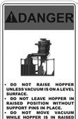
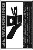

49 MAINTENANCE Hazard Identification Decals (cont.) Vacmaster 5T Electric Abrasive Vacuums 48


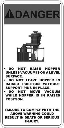
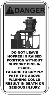
50 MAINTENANCE Hazard Identification Decals (cont.) 49 Vacmaster 5T Electric Abrasive Vacuums

 Vacmaster 5T")
51 MAINTENANCE Hazard Identification Decals (cont.) Vacmaster 5T Electric Abrasive Vacuums 50
52 TROUBLESHOOTING W-562 Always depressurize the entire system, disconnect all power sources and lockout/ tagout all components before any maintenance or troubleshooting is attempted. Failure to warning could cause electrical shock and inadvertent activation of equipment resulting in If the Vacmaster 5T Electric Abrasive Vacuums does not function properly, check the following: SYMPTOM (Cause) Drive Belt slips or vibrates (Loose connections, worn parts) Magnehelic Gauge reading greater than normal operating range (Hopper Filter Bags) ACTION Inspect Blower Drive Belt for damage. Replace as needed. Inspect alignment. Adjust Blower Drive Belt Tension. See Adjust Blower Drive Belt Tension. A reading greater than 40 (w.c) on Magnehelic Gauge indicates clogged filters. Decrease engine RPM to idle speed and disengage clutch while allowing engine to run. Pulsers will clean down the filters. Once gauge reads back into the normal operation range of 20" 0" (w.c), re-engage clutch and increase RPM to operating speed. If Magnehelic Gauge is reading above 0" (w.c.), perform After Use procedure. Inspect Pulser System and Filters. Replace filter bags, if needed. If Magnehelic Gauge is reading above 40" (w.c.), shut down unit immediately. Replace filter bags. 5 Vacmaster 5T Electric Abrasive Vacuums
53 TROUBLESHOOTING W-562 Always depressurize the entire system, disconnect all power sources and lockout/ tagout all components before any maintenance or troubleshooting is attempted. Failure to warning could cause electrical shock and inadvertent activation of equipment resulting in W-586 Moving parts can present an area where crushing, pinching, entanglement or amputation may occur. Do not place body parts or foreign objects in any area where there are moving parts. SYMPTOM (Cause) Filter Pulser System pressurizes but does not pulse (No power to control box, blown fuse in control box or timer board, disconnected wires, timer board, solenoid, diaphragm valve) Pulser System leaks (Loose or missing hoses or connections, loose or missing urethane tubing, damaged diaphragm valves) ACTION Inspect all power connections. Repair or replace faulty connections. Turn main power switch "OFF". Replace fuse if required. Inspect all solenoids and listen for audible sound as it engages to pulse. Replace solenoid. Inspect diaphragm valve breather vent for obstruction. Check hose and hose connections between diaphragm valves and hopper wall. Check all tubing for secure connections and fittings. If fittings do not fit tightly in hose, cut a small section from the end of the hose and re-insert fitting in tube. Inspect diaphragm valve for damage or debris. Repair or replace diaphragm valve. Vacmaster 5T Electric Abrasive Vacuums 52
54 ASSEMBLY PART NUMBERS AND SCHEMATICS Front Assembly Item # Part # Description Fig Jet Port Inlet Flange /4-0 x 2-/2" Hex Bolt (6 Required) /4" Flat Washer (2 Required) /4" Lock Washer (6 Required) /4-0 Hex Nut (6 Required) " Raincap /8-9 x 2-/2" Grade 5 Zinc Bolt (24 Required) /8" Flat Washer - Zinc (48 Required) /8" Lock Washer - Zinc (24 Required) /8-8 Gr 5 Zinc Nut (24 Required) " Exhaust Silencer End " Discharge Silencer " Jet Port Silencer Intake Filter Housing Cap Air Filter Housing Gasket Intake Filter Housing 7 20PFBA09564 /4" Tube x /4" NPT 90 (Two Required) Electric Vacuum Skid Frame /4-0 x -5/8" Grade 5 Zinc Bolt (20 Required) /4" Lock Washer (20 Required) /4" Flat Washer (20 Required) /8-9 x 2" Grade 5 Zinc Bolt (2 Required) /8" Flat Washer - Zinc (2 Required) /8" Lock Washer - Zinc (2 Required) /2- x 2" Grade 8 Bolt (Four Required) Item # Part # Description /2" Grade 8 Flat (Eight Required) /2" Grade 8 Lock Washer (Four Required) " Discharge Elbow Blower Top Shaft Left Discharge " Inlet Elbow Weldment 0094 /2-0 Hex Nut /2" Flat Washer Rubber Washer -/4" OD x /8" ID x /8" Filter Cartridge 2.75" x 8.8" x 6" - Flange -.54" BH Belt Guard Belt Guard /8-6 x /4" Bolt (Eight Required) 0959 Hazard Identification Decals - 00HP 200HP Electric Vacuum Labels 05M55 Features & Specifications Guide Vacmaster 5T Electric Abrasive Vacuums 06M55 Part Numbers & Schematics Guide Vacmaster 5T Electric Abrasive Vacuums 0955 Operator's Manual Vacmaster 5T Electric Abrasive Vacuums 5 Vacmaster 5T Electric Abrasive Vacuums
55 PART NUMBERS AND SCHEMATICS Figure : Front Assembly 2,,4,5 6 7,8,9, ,2, ,20,2 8 9,20,2 22,2,24 7 2,,4, ,26, ,8,9,0 Vacmaster 5T Electric Abrasive Vacuums 54
56 PART NUMBERS AND SCHEMATICS Front Assembly with with Sound Reduction Package Item # Part # Description Fig Jet Port Inlet Flange /4-0 x 2-/2" Hex Bolt (2 Required) /4" Flat Washer (64 Required) /4" Lock Washer (2 Required) /4-0 Hex Nut (2 Required) " Secondary Jet Port Silencer " Raincap /8-9 x 2-/2" Grade 5 Zinc Bolt (44 Required) /8" Flat Washer - Zinc (88 Required) /8" Lock Washer - Zinc (44 Required) /8"-8 Gr 5 Zinc Nut (44 Required) /8-6 x -/4" Shoulder Bolt (Four Required) /8" Flat Washer Galvanized (0 Required) /8" Lock Washer - Zinc (Six Required) /8"-6 HD Hex Nut (Six Required) " Exhaust Silencer End " Silencer Support Strap (Two Required) " Jet Port Inlet Elbow " Exhaust Elbow " Discharge Silencer " Jet Port Silencer Intake Filter Housing Cap Air Filter Housing Gasket Intake Filter Housing 25 20PFBA09564 /4" Tube x /4" NPT 90 (Two Required) Electric Vacuum Skid Frame Item # Part # Description /8-6 x -/4 Hex Bolt Zinc (Two Required) Silencer Support Angle " Silencer Strap (Two Required) /4-0 x -5/8" Grade 5 Zinc Bolt (20 Required) /4" Lock Washer (20 Required) /4" Flat Washer (20 Required) /8-9 x 2" Grade 5 Zinc Bolt (2 Required) /8" Flat Washer - Zinc (2 Required) /8" Lock Washer - Zinc (2 Required) /2- x 2" Grade 8 Bolt (Four Required) /2" Grade 8 Flat (Eight Required) /2" Grade 8 Lock Washer (Four Required) " Discharge Elbow Blower Top Shaft Left Discharge " Inlet Elbow Weldment /2-0 Hex Nut /2" Flat Washer Rubber Washer.25 OD x.75 ID x Filter Cartridge 2.75" x 8.8" x 6" - Flange -.54" BH 05M2 Features & Specifications Guide Vacmaster 5T Electric Abrasive Vacuums 06M2 Part Numbers & Schematics Guide Vacmaster 5T Electric Abrasive Vacuums 0902 Operator's Manual Vacmaster 5T Electric Abrasive Vacuums 55 Vacmaster 5T Electric Abrasive Vacuums


57 PART NUMBERS AND SCHEMATICS Figure 2: Front Assembly with with Sound Reduction Package 2,,4,5 2,,4,5 6 8,9,0, 7 2,,4,5 2,,4,5 6 8,9,0, ,,4,5 29 8,9,0, ,,4,5 42,4, ,,2 26 0,,2,4,5 25 2,,4, ,7,8 8,9,0, Vacmaster 5T Electric Abrasive Vacuums 56
58 PART NUMBERS AND SCHEMATICS Top Assembly Item # Part # Description Fig Vacuum Butterfly Cover /8" Flat Washer - Galvanized ( Required) /8-6 x /4" Bolt (Four Required) Butterfly Cover Mount Weldment " Butterfly " Extension Spring Piston Rod Clevis Vacuum Butterfly Cylinder Weldment Butterfly Actuating Arm /4-20 x /4" Zinc Hex Bolt "Pneumatic Cylinder /4" Street Elbow 027 Galvanized /4" x 2" Nipple Solenoid For Butterfly 5 20PFHA60UA0406 /4" (M) x /8" (F) 90 Swivel Humphrey Din Connector /8-6 x 2-/2" Thread Stud /2" Flat Washer (Eight Required) /2 - Hex Lock Nut (Eight Required) Over Center Clamp (2 Required) 2 20PFHA60UA0606 /8" (M) x /8" (F) 90 Swivel (Two Required) Auxiliary Header /8-6 x " Bolt (Four Required) /8" Lock Washer - Zinc (Four Required) /8-6 Hex nut (Four Required) Vacuum Lid Weldment Vacuum Hopper Section Gasket " Long Extension Spring - Zinc 57 Vacmaster 5T Electric Abrasive Vacuums


59 PART NUMBERS AND SCHEMATICS Figure : Top Assembly , ,24,25, Vacmaster 5T Electric Abrasive Vacuums 58
60 PART NUMBERS AND SCHEMATICS Rear Assembly Item # Part # Description Fig " Differential Pressure Gauge " Quick Disconnect Coupling APV Series Piston Vibrator (See figure 6) Dump Door Vacuum Hopper Cone Vacuum Wear Door Wear Door Only Wear Door Liner Only Bulldog Trailer Jack Knappco Hatch Vacuum Lid Overcenter Clamp (2 Required) Vacuum Header (See figure 8) 088 /2" x /4" Galvanized Bushing /2" NPT -Way Brass Ball Valve 20PFHA60UA0406 /4" (M) x /8" (F) 90 Swivel (Two Required) " Pneumatic Cylinder Piston Rod Clevis Dump Arm /8-6 x -/4 Hex Bolt Zinc (Four Required) /8" Flat Washer (22 Required) /8" Lock Washer - Zinc (6 Required) /8-6 Hex Nut (Four Required) Dump Door Gasket Dump Door Internal Plate /2- x 4-/2" Hex Bolt /2" Flat Washer (Two Required) /2- Hex Lock Nut 25 20PFHA25UA0404 /4" Male 90 Elbow Item # Part # Description /4-20 x -/4" Zinc Bolt (Two Required) /4-20 Zinc Lock Nut with Nylon Insert (Two Required) Solenoid Breather Vent Series MPR Mini Pressure Regulator 0L8005 /2" Close Nipple /2" Straight Conduit Body Cord Grip /2" Nylon Diameter Pressure Gauge 00 Psi /8" /4" Ball Valve 6 20PFHA60SG0406 /4"F x /8"F Swivel Union (Two Required) 7 20PFHA24SA0404 /4" Hex Nipple (Three Required) /8" x /8" 90 Fitting /4" NPT x /2" Nipple 40 20PFHA60SA0806 /2"M x /8"F Swivel Union /2" Street Elbow 42 20PFBA09564 /4" Tube x /4" NPT /8"-6 Hex Nut (4 Required) Magnehelic Mount Inlet Elbow Weldment Inlet Adapter Weldment /8" Flat Washer - Galv. (Eight Required) /8-6 Hex Nut GALV. (Four Required) /8-6 x " Bolt - Zinc ( Required) 50 0AH08 Air Hose /8" ID 00 Psi 09V52 Operator's Manual - Blower 59 Vacmaster 5T Electric Abrasive Vacuums


61 PART NUMBERS AND SCHEMATICS Figure 4: Rear Assembly , ,9, ,48, , ,2, ,8,9,20 6 Vacmaster 5T Electric Abrasive Vacuums 60
62 PART NUMBERS AND SCHEMATICS Left Side Assembly Item # Part # Description Fig /8-6 x -/4" Hex Bolt Zinc (Eight Required) /8" Flat Washer - Galvanized (40 Required) 0096 /8" Lock Washer - Zinc ( Required) /8-6 Hex Nut ( Required) Vacuum Lid Lift Vacuum Top Section Bulldog Trailer Jack 8 20PFHA60SA0606 Union Swivel /8" (M) x /8" (F) (Two Required) /8" NPT Tee (Two Required) 0 20PFHA60UA0606 /8"M x /8"F 90 Swivel Union 0209 /8 NPT Close Nipple " Rubber Cushioned Loop Clamp (Five Required) 0L80502 Jr & Sr Spindle Bolt (Three Required) /4-28 Coupling Nut (Three Required) Vacuum Control Timer Amp 50-Volt Rectifier Enclosure Panel For 7605k /4-20 x /4" Zinc Hex Bolt (Eight Required) /4" Flat Washer - (Four Required) /4-20 Stainless Steel Lock Nut with Nylon Insert (Four Required) Cord Grip Nylon /2"- NPT Diameter " 90 Conduit Hub Female Twist Plug Prong 24 20RCG5050 Cord Grip /2"-NPT Diameter Item # Part # Description Selector Switch - 2-Way (Three Required) 26 20RST50 Straight Liquid Tite Connector Fitting " x 4" x 5" Fiberglass Qr Latch Enclosure 28 0ME Coupling 2-Lug Male /4" Series Filter/Regulator Pressure Gauge 60 Psi /4" 007 /4" x 2" 5 Nipple 2 20PFHA24SB206 /4" x /8" Reducing Bushing Hitch Pin - /4" x 6-/2" Long Vacuum Control Panel /4-20 x Hex Bolt /4" Flat Washer /4-20 Stainless Steel Lock Nut With Nylon Insert Red NC Momentary Switch Black NO Momentary Switch Red Indicating light 20 VAC Green Indicating light 20 VAC Black Handle Mechanism Twist Release E-Stop Green Indicating light 20 VAC Black Normally Open Momentary Switch Red Normally Closed Momentary switch Red Indicating light 20 VAC 48 0AH08 Air Hose /8" Is 00 Psi Urethane Tube - Black - /4" 6 Vacmaster 5T Electric Abrasive Vacuums


63 PART NUMBERS AND SCHEMATICS Figure 5: Left Side Assembly,2,,4 5 6,2,, ,5,6, , ,9, Vacmaster 5T Electric Abrasive Vacuums 62
64 PART NUMBERS AND SCHEMATICS Right Side Assembly Item # Part # Description Fig " Double Bolt Clamp (Two Required) /8" Flat Washer (Five Required) " Bandlock Clamp /5V 7.0" Sheave (Two Required) /8-6 x -/4" Shoulder Bolt (Seven Required) /8" Lock Washer - Zinc (Seven Required) SF Bushing 2" Bore E Bushing 2-7/8" Bore /8" NPT Tee Strand 5VP600 Belt - 60" 0047 /4-0 UNC x -/4" Bolt (Four Required) Washer - /4" (Four Required) HP Motor Base " Straight Conduit Hub HP Phase Electric Motor /4-0 UNC Nut (Four Required) Lock Washer - /4" (Four Required) " Differential Pressure Gauge " 90 Elbow Non-Plated 20 20PFHA60UA0606 /8"M x /8"F 90 Swivel Union 2 20PFHA60SA0606 Union Swivel /8" (M) x /8" (F) (Three Required) /8 NPT Close Nipple 2 20PFHA25UG0606 /8" Street Elbow 24 20PFHA24SB0806 /2" x /8" Reducing Bushing (Two Required) Lubricator /2" NPT 56 CFM Item # Part # Description /8" NPT Full Port Brass Ball Valve (Two Required) " Rubber Cushioned Loop Clamp /8-6 Hex Nut Airline Drain 0 20RCG5050 /2" Npt x Diameter Cord Grip (Two Required) Vibrator Solenoid 2 20PFHA60UA0406 /4" (M) x /8" (F) 90 Swivel (Two Required) /2" Npt x.2.47 Diameter Nylon Cord Grip (Three Required) /4-20 Stainless Steel Lock Nut with Nylon Insert (Four Required) /4" Flat Washer - Galvanized (Four Required) /4-20 x /4" Zinc Hex Bolt (Four Required) " Rubber Cushioned Loop Clamp (0 Required) 8 0L80502 Jr & Sr Spindle Bolt (0 Required) /4-28 Coupling Nut (0 Required) 40 20PFHA60SA0606 Union Swivel /8" (M) x /8" (F) (Three Required) /8" NPT Tee /8-6 X -/4 Hex Bolt Zinc Gr /8"-6 Hex Nut Galvanized 44 0VH620B Ureflex 6" ID Vac Hose 20' Section 45 0AH08 Air Hose /8" Is 00 Psi 09V56 Operator s Manual WEG Electric Motor Manual 6 Vacmaster 5T Electric Abrasive Vacuums


65 PART NUMBERS AND SCHEMATICS Figure 6: Right Side Assembly ,5, ,4, ,5,6, , ,7 4 0,2 5, Vacmaster 5T Electric Abrasive Vacuums 64
 000674 /2\" Flat Washer (Two Required) 4 002652 /2- x 2-/4\" Grade 5 Bolt (Two Required) 5 20PFHA60UA0406 /4\" (M) x")
66 PART NUMBERS AND SCHEMATICS Figure 7: Pneumatic Piston Vibrators 2,, ,,4 Item # Part # Description Fig APV Series Piston Vibrator /2- Hex Lock Nut - Zinc (Two Required) /2" Flat Washer (Two Required) /2- x 2-/4" Grade 5 Bolt (Two Required) 5 20PFHA60UA0406 /4" (M) x /8" (F) 90 Swivel Union 6 0AH08 Air Hose /8" Is 00 Psi 65 Vacmaster 5T Electric Abrasive Vacuums

67 PART NUMBERS AND SCHEMATICS Figure 8: Filter Bag Pulsers Item # Part # Description Fig T-Bolt Hose Clamp For " I.D. (0 Required) " 75W Marine Hose - 00 PSI (Five Required) Pulser System Short Blowpipe (Two Required) Pulser System Medium Blowpipe (Two Required) " Flexible Tubing For Blowpipes (Two Required) Pulser System Long Blowpipe (Three Required) Vacuum Baghouse Filter (7 Required) Vacuum Baghouse Filter Cage (7 Required) Vacmaster 5T Electric Abrasive Vacuums 66
68 PART NUMBERS AND SCHEMATICS Pulser System Assembly Item # Part # Description Fig /8" Flat Washer - Galvanized (Eight Required) /8" Lock Washer - Zinc (Four Required) 0747 /8-6 x " Bolt (Four Required) /8-6 Hex Nut (Four Required) 5 20PFHA60UA0606 /8"M x /8"F 90 Swivel Union Vacuum Header T-Bolt Hose Clamp For " I.D. (0 Required) Air Hose " ID 200 psi - Red /4" NPT x -/2" Toe Nipple (Five Required) Humphrey Din Connector (Included with Item #) (Five Required) /4" Diaphragm Valve with Solenoid (Five Required) Pilot Valve Repair Kit 0079 Diaphragm Repair Kit 67 Vacmaster 5T Electric Abrasive Vacuums


69 PART NUMBERS AND SCHEMATICS Figure 9: Pulser System Assembly ,2,, Vacmaster 5T Electric Abrasive Vacuums 68
70 PART NUMBERS AND SCHEMATICS Wear Plates and Baffles Item # Part # Description Fig /8" Flat Washer - Galvanized (5 Required) /8" Lock Washer - Zinc (5 Required) 0098 /8-6 Hex Nut (5 Required) /8-6 x " Bolt (5 Required) Vacuum Wear Plates (Four Required) Vacuum Baffle (Three Required) /8-6 FH Sq Neck x " Bolt Zinc (6 Required) /8" Flat Washer - Galvanized (20 Required) /8" Lock Washer - Zinc (6 Required) /8-6 Hex Nut GALV. (2 Required) /8-6 FH SQ Neck x " Bolt Zinc (2 Required) Wear Door Liner Wear Door 69 Vacmaster 5T Electric Abrasive Vacuums

71 PART NUMBERS AND SCHEMATICS Figure 0: Wear Plates and Baffles,2,,2,, ,9,0, 7 5 Vacmaster 5T Electric Abrasive Vacuums 70

 4 00400 /8-6 x /4\" Bolt (72 Required) 5 00625 Top Panel Hold On's (Four Required) 6 0069")

72 PART NUMBERS AND SCHEMATICS Figure : Sound Panels and Straps Item # Part # Description Fig Sound Panel (Two Required) Sound Panel (Three Required) Panel Hold On's (6 Required) /8-6 x /4" Bolt (72 Required) Top Panel Hold On's (Four Required) Top Sound Panel - Discharge Top Sound Panel - Jet Port (Two Required) Top Sound Panel - Filter Housing Top Sound Panel - Discharge Top Sound Panel - Filter Housing Sound Panel Sound Panel Sound Panel 5 7 Vacmaster 5T Electric Abrasive Vacuums
) 05552 Female twist lock plug two prong 2 00407 E-Stop Control Station 0555")
 2000002 8-2")
73 PART NUMBERS AND SCHEMATICS Figure 2: Emergency-Stop Station Item # Part # Description Fig Remote Emergency-Stop Station (Includes Item #'s: 2, 4, 5, and 6 (00')) Female twist lock plug two prong E-Stop Control Station 0555 Male Twist Lock Plug Two Prong Cord Grip Nylon /2"-NPT Diameter Legend Plate - Emergency Stop /2 Xtreme Duty Power Cord - Red x " Pan Head Phillips Screw (Four Required) Zinc Nut (Four Required) #8 Zinc Lock Washer (Four Required) #8 Zinc Flat Washer (Four Required) Vacmaster 5T Electric Abrasive Vacuums 72
74 MAINTENANCE NOTES DATE TYPE OF SERVICE PART NUMBER 7 Vacmaster 5T Electric Abrasive Vacuums
75 ADDITIONAL TECHNICAL DATA The associations listed below offer information, materials and videos pertaining to abrasive blasting and safe operating practices. American Society for Testing and Materials (ASTM) 00 Barr Harbor Drive West Conshohockon, PA Phone: (60) FAX: (60) Occupational Safety & Health Administration (OSHA) United States Department of Labor 200 Constitution Avenue Washington, DC 2020 Phone: (800) 2-OSHA (800) The National Board of Boiler & Pressure Vessel Inspectors 055 Crupper Avenue Columbus, Ohio 422 Phone: (64) FAX: (64) National Association of Corrosion Engineers (NACE) 440 South Creek Drive Houston, TX Phone: (28) FAX: (28) The Society for Protective Coatings (SSPC) 40-24th Street, 6th Floor Pittsburgh, PA Phone: (42) 28-2 FAX: (42) American National Standards Institute (ANSI) 899 L Street, NW, th Floor Washington, DC 2006 Phone: (202) FAX: (202) LIMITED WARRANTY Seller warrants to the original purchaser that the Product covered by this Limited Warranty will remain free from defects in workmanship or material under normal commercial use and service for a period of one year from the date of shipment to the original Purchaser. This Warranty shall not apply to defects arising, in whole or in part, from any accident, negligence, alteration, misuse or abuse of the Product, operation of the Product which is not in accordance with applicable instructions or manuals or under conditions more severe than, or otherwise exceeding, those set forth in the written specifications for the Product, nor shall this Warranty extend to repairs or alterations of the Product and/or any maintenance part by persons other than Seller or Seller s authorized representatives. This warranty does not apply to accessory items. Further, this Warranty does not apply to damage or wear to the surface finish or appearance of the Product or normal wear and tear to the Product. This Warranty is limited to a purchaser who purchases the Product either directly from the Seller or from one of Seller s Authorized Distributors. An Authorized Distributor is a Seller approved distributor that purchases the Product directly from the Seller for the sole purpose of re-selling the Product at retail, without any use or modifications whatsoever, to an end-purchaser. This warranty is specifically non-assignable and non-transferable. DISCLAIMER OF WARRANTY The foregoing Limited Warranty is exclusive and is in lieu of all other warranties, whether oral or written and whether express, implied, or statutory. SELLER HEREBY DISCLAIMS ALL OTHER WARRANTIES, INCLUDING BUT NOT LIMITED TO THE WARRANTIES OF MERCHANTABILITY AND/OR FITNESS FOR A PARTICULAR PURPOSE AND ALL SUCH OTHER WARRANTIES ARE HEREBY EXCLUDED AND ARE INAPPLICABLE TO THE PRODUCT. Seller makes no warranties or representations of any kind concerning respirators, or equipment made by other manufacturers. Seller s agents and representatives are not authorized to offer any further warranties. EXCLUSIVE REMEDY FOR WARRANTY CLAIMS THE SOLE AND EXCLUSIVE REMEDY UNDER THE FOREGOING LIMITED WARRANTY, AND TO THE EX- TENT PERMITTED BY LAW, ANY WARRANTY OR CONDITION IMPLIED BY LAW, COVERING THIS PROD- UCT SHALL BE, AT THE SELLER S OPTION, THE REPAIR OR REPLACEMENT, FREE OF CHARGE, F.O.B. POINT OF MANUFACTURE, OF ANY DEFECTIVE PART OR PARTS OF THE PRODUCT THAT WERE MANU- FACTURED BY SELLER, AND WHICH ARE RETURNED TO SELLER AT SELLER S PRINCIPAL PLACE OF BUSINESS, POSTAGE PREPAID BY THE PURCHASER. THIS SOLE AND EXCLUSIVE REMEDY IS CON- DITIONED UPON PURCHASER S PROMPT WRITTEN NOTICE TO SELLER AT SELLER S PLACE OF BUSI- NESS THAT A DEFECT HAS BEEN DISCOVERED, TOGETHER WITH A REASONABLY DETAILED DESCRIP- TION OF THE DEFECT IN THE PRODUCT, PROOF OF PURCHASE OF THE PRODUCT, AND THE MODEL AND IDENTIFICATION NUMBER OF THE PRODUCT WITHIN THIRTY (0) DAYS AFTER DISCOVERY OF THE DEFECT, OTHERWISE SUCH CLAIMS SHALL BE DEEMED WAIVED. NO ALLOWANCE WILL BE GRANTED FOR ANY REPAIRS OR ALTERATIONS MADE BY PURCHASER OR OTHERS WITHOUT SELLER S PRIOR WRITTEN CONSENT. IF SUCH NOTICE IS TIMELY GIVEN, SELLER WILL HAVE THE OPTION TO EITHER MODIFY THE PRODUCT OR COMPONENT PART THEREOF TO CORRECT THE DEFECT, REPLACE THE PRODUCT OR PART WITH COMPLYING PRODUCTS OR PARTS, OR REFUND THE AMOUNT PAID FOR THE DEFECTIVE PRODUCT, ANY ONE OF WHICH WILL CONSTITUTE THE SOLE LIABILITY OF SELLER AND FULL SETTLEMENT OF ALL CLAIMS. IN NO EVENT SHALL SELLER BE LIABLE FOR ANY OBLIGATION GREATER THAN THE ORIGINAL PURCHASE PRICE OF THE PRODUCT UNDER THIS WARRANTY. PUR- CHASER SHALL AFFORD SELLER PROMPT AND REASONABLE OPPORTUNITY TO INSPECT THE PROD- UCT FOR WHICH A CLAIM IS MADE. THE SOLE PURPOSE OF THE FOREGOING STIPULATED EXCLUSIVE REMEDY SHALL BE TO REPAIR OR REPLACE DEFECTIVE PRODUCTS OR COMPONENTS THEREOF, OR TO REFUND PURCHASER THE PURCHASE PRICE THEREOF. THIS STIPULATED EXCLUSIVE REMEDY SHALL NOT BE DEEMED TO HAVE FAILED OF ITS ESSENTIAL PURPOSE SO LONG AS SELLER IS WILL- ING AND ABLE TO REPAIR OR REPLACE THE DEFECTIVE PARTS OR REFUND THE PURCHASE PRICE IN ACCORDANCE WITH THE TERMS HEREOF. PRODUCTS THAT HAVE BEEN REPAIRED OR REPLACED UN- DER THIS WARRANTY DO NOT RECEIVE A NEW WARRANTY AND ARE ONLY COVERED BY THE REMAIN- ING PORTION OF THE ORIGINAL WARRANTY. LIMITATION OF REMEDIES The foregoing stipulated exclusive remedy is in lieu of all other remedies for breach of contract, warranty, and/or tort or otherwise. Seller shall not be liable, either directly or indirectly, for any consequential, incidental or special losses or damages of Purchaser, including but not limited to the Purchaser s expenses for downtime or for making up downtime, damages for which the Purchaser may be liable to other persons and/or entities, damages to property, and injury to or death of any persons and/or any claims for incidental or consequential damages, including but not limited to loss of profits, regardless of whether Seller has been informed of the possibility of such damages. Seller neither assumes, nor authorizes any person to assume for it, any other liability in connection with the sale or use of any Products covered by the foregoing Warranty and Disclaimers, and there are no oral agreements relating to remedies which are collateral to or which affect this limitation. Vacmaster 5T Electric Abrasive Vacuums 74

76 40+ NATIONWIDE SHIPPING LOCATIONS GLOBAL HEADQUARTERS 425 East Locust Street Davenport, IA 5280 ph: 800.BLAST.IT ( ) ph: fax: REGIONAL BRANCH OFFICES Iowa Davenport Louisiana Gonzales Harvey Lafayette Ohio Youngstown Texas Beaumont Corpus Christi Deer Park Marco Regional Branch Offices and Shipping Locations Direct Shipping Locations ABRASIVES BLASTING COATING DUST COLLECTORS ENGINEERED SYSTEMS RENTAL SAFETY SERVICE & REPAIR VACUUMS CONTACT MARCO 800.BLAST.IT ( ) FAX: Marco and Blastmaster are registered trademarks of Marco. All other brand names or marks are used for identification purposes and are trademarks of their respective owners. Part # 0956_0/4/6
SERVICE MANUAL DUSTMASTER 50,000 CFM ELECTRIC DUST COLLECTORS
 SERVICE MANUAL DUSTMASTER 50,000 CFM ELECTRIC DUST COLLECTORS Before using this equipment, read, understand and follow all instructions in the Operator s Manuals provided with this equipment. If the user
OPERATOR S MANUAL DUSTMASTER 18,000 CFM TIER III DIESEL DUST COLLECTORS
 OPERATOR S MANUAL DUSTMASTER 8,000 CFM TIER III DIESEL DUST COLLECTORS Before using this equipment, read, understand and follow all instructions in the Operator s Manuals provided with this equipment.
OPERATOR S MANUAL BLASTMASTER 130E REMOTE CONTROL SYSTEM
 OPERATOR S MANUAL BLASTMASTER 30E REMOTE CONTROL SYSTEM Before using this equipment, read, understand and follow all instructions in the Operator s Manuals provided with this equipment. If the user and/
OPERATOR S MANUAL BLASTMASTER 750 CFM AIR DRYER
 OPERATOR S MANUAL BLASTMASTER 750 CFM AIR DRYER Before using this equipment, read, understand and follow all instructions in the Operator s Manuals provided with this equipment. If the user and/ or assistants
BLASTMASTER 160 CU. FT. ABRASIVE BLASTING POTS
 OPERATOR S MANUAL BLASTMASTER 160 CU. FT. ABRASIVE BLASTING POTS Highway Trailer Yard Trailer Offshore Fork-Pocket Skid Stationary Before using this equipment, read, understand and follow all instructions
OPERATOR S MANUAL BLASTMASTER 60 CU. FT. ABRASIVE BLASTING POTS
 OPERATOR S MANUAL BLASTMASTER 60 CU. FT. ABRASIVE BLASTING POTS Before using this equipment, read, understand and follow all instructions in the Operator s Manuals provided with this equipment. If the
OPERATOR S MANUAL BLASTMASTER 6.5 CU. FT. HP-SERIES ABRASIVE BLASTING POT
 OPERATOR S MANUAL BLASTMASTER 6.5 CU. FT. HP-SERIES ABRASIVE BLASTING POT Before using this equipment, read, understand and follow all instructions in the Operator s Manuals provided with this equipment.
BLASTMASTER CONEBLAST INTERNAL PIPE BLASTING TOOL
 BLASTMASTER CONEBLAST INTERNAL PIPE BLASTING TOOL PART NUMBERS AND SCHEMATICS GUIDE Company Profile Since 19, Marco has developed a strong tradition of providing innovative and reliable products and services
BLASTMASTER 2.0 CU. FT. L-SERIES ABRASIVE BLASTING POT
 BLASTMASTER 2.0 CU. FT. L-SERIES ABRASIVE BLASTING POT PART NUMBERS AND SCHEMATICS GUIDE Company Profile Since 1944, Marco has developed a strong tradition of providing innovative and reliable products
BLASTMASTER 250 CFM 12-VOLT DC AFTERCOOLER
 BLASTMASTER 250 CFM 12-VOLT DC AFTERCOOLER PART NUMBERS AND SCHEMATICS GUIDE Company Profile Since 1944, Marco has developed a strong tradition of providing innovative and reliable products and services
BLASTMASTER MAXUM I ABRASIVE METERING VALVE
 BLASTMASTER MAXUM I ABRASIVE METERING VALVE PART NUMBERS AND SCHEMATICS GUIDE Company Profile Since 1944, Marco has developed a strong tradition of providing innovative and reliable products and services
BLASTMASTER 400 CFM 12-VOLT DC AFTERCOOLER
 BLASTMASTER 400 CFM 12-VOLT DC AFTERCOOLER Company Profile Since 1944, Marco has developed a strong tradition of providing innovative and reliable products and services to the surface preparation and protective
GRACO 395ST PRO ELECTRIC AIRLESS SPRAY PUMP
 GRACO 395ST PRO ELECTRIC AIRLESS SPRAY PUMP PART NUMBERS AND SCHEMATICS GUIDE Company Profile Since 1944, Marco has developed a strong tradition of providing innovative and reliable products and services
CLEMCO CPF BREATHING AIR FILTERS
 CLEMCO CPF BREATHING AIR FILTERS PART NUMBERS AND SCHEMATICS GUIDE Company Profile Since 1944, Marco has developed a strong tradition of providing innovative and reliable products and services to the surface
BLASTMASTER 1.5 CU. FT. L-SERIES ABRASIVE BLASTING POT
 BLASTMASTER 1.5 CU. FT. L-SERIES ABRASIVE BLASTING POT PART NUMBERS AND SCHEMATICS GUIDE Company Profile Since 1944, Marco has developed a strong tradition of providing innovative and reliable products
SPRAYMASTER ELEVATOR AGITATOR 5 GALLON (20 LITER) CONTAINER
 CONTAINER") SPRAYMASTER ELEVATOR AGITATOR 5 GALLON (20 LITER) CONTAINER PART NUMBERS AND SCHEMATICS GUIDE Company Profile Since 1944, Marco has developed a strong tradition of providing innovative and reliable products
SPRAYMASTER ELEVATOR AGITATOR 5 GALLON (20 LITER) CONTAINER PART NUMBERS AND SCHEMATICS GUIDE Company Profile Since 1944, Marco has developed a strong tradition of providing innovative and reliable products
BLASTMASTER 123E REMOTE CONTROL SYSTEM
 BLASTMASTER 123E REMOTE CONTROL SYSTEM PART NUMBERS AND SCHEMATICS GUIDE Company Profile Since 1944, Marco has developed a strong tradition of providing innovative and reliable products and services to
SPRAYMASTER 60 GALLON HEATED COATING TANK
 SPRAYMASTER 60 GALLON HEATED COATING TANK PART NUMBERS AND SCHEMATICS GUIDE Company Profile Since 1944, Marco has developed a strong tradition of providing innovative and reliable products and services
OPERATOR S MANUAL BLASTMASTER REGULATOR JR. ABRASIVE METERING VALVE
 OPERATOR S MANUAL BLASTMASTER REGULATOR JR. ABRASIVE METERING VALVE Before using this equipment, read, understand and follow all instructions in the Operator s Manuals provided with this equipment. If
CLEMCO APOLLO 600 BLASTING HELMET
 CLEMCO APOLLO 600 BLASTING HELMET PART NUMBERS AND SCHEMATICS GUIDE Company Profile Since 1944, Marco has developed a strong tradition of providing innovative and reliable products and services to the
OPERATOR S MANUAL BLASTMASTER 155E AND 156E REMOTE CONTROL SWITCHES
 OPERATOR S MANUAL BLASTMASTER 155E AND 156E REMOTE CONTROL SWITCHES Before using this equipment, read, understand and follow all instructions in the Operator s Manuals provided with this equipment. If
BLASTING HELMET PACKAGES
 BLASTING HELMET PACKAGES PART NUMBERS AND SCHEMATICS GUIDE Company Profile Since 1944, Marco has developed a strong tradition of providing innovative and reliable products and services to the surface preparation
BLASTMASTER 130P REMOTE CONTROL SYSTEM CONVERSION KITS
 BLASTMASTER 130P REMOTE CONTROL SYSTEM CONVERSION KITS PART NUMBERS AND SCHEMATICS GUIDE Company Profile Since 1944, Marco has developed a strong tradition of providing innovative and reliable products
OPERATOR S MANUAL SPRAYMASTER 60 GALLON HEATED COATING TANK
 OPERATOR S MANUAL SPRAYMASTER 60 GALLON HEATED COATING TANK Before using this equipment, read, understand and follow all instructions in the Operator s Manuals provided with this equipment. If the user
GRACO POLE GUN WITH CLEANSHOT SHUT-OFF VALVE AND CONTRACTOR IN-LINE VALVE
 GRACO POLE GUN WITH CLEANSHOT SHUT-OFF VALVE AND CONTRACTOR IN-LINE VALVE PART NUMBERS AND SCHEMATICS GUIDE Company Profile Since 1944, Marco has developed a strong tradition of providing innovative and
OPERATOR S MANUAL BLASTMASTER 155E REMOTE CONTROL SWITCH
 OPERATOR S MANUAL BLASTMASTER 155E REMOTE CONTROL SWITCH Before using this equipment, read, understand and follow all instructions in the Operator s Manuals provided with this equipment. If the user and/
OPERATOR S MANUAL BARRICADE 286 AIRLINE FILTERS
 OPERATOR S MANUAL BARRICADE 286 AIRLINE FILTERS Before using this equipment, read, understand and follow all instructions in the Operator s Manuals provided with this equipment. If the user and/ or assistants
FINISHING BRANDS PAINT TANK GALVANIZED
 FINISHING BRANDS PAINT TANK GALVANIZED PART NUMBERS AND SCHEMATICS GUIDE Company Profile Since 1944, Marco has developed a strong tradition of providing innovative and reliable products and services to
GRACO G40 AIR-ASSISTED SPRAY GUNS
 GRACO G40 AIR-ASSISTED SPRAY GUNS PART NUMBERS AND SCHEMATICS GUIDE Company Profile Since 1944, Marco has developed a strong tradition of providing innovative and reliable products and services to the
OPERATOR S MANUAL BLASTMASTER CONEBLAST INTERNAL PIPE BLASTING TOOL
 OPERATOR S MANUAL BLASTMASTER CONEBLAST INTERNAL PIPE BLASTING TOOL Before using this equipment, read, understand and follow all instructions in the Operator s Manuals provided with this equipment. If
GRACO KING 56:1 AIRLESS SPRAY PUMP
 GRACO KING 56:1 AIRLESS SPRAY PUMP PART NUMBERS AND SCHEMATICS GUIDE Company Profile Since 1944, Marco has developed a strong tradition of providing innovative and reliable products and services to the
OPERATOR S MANUAL BLASTMASTER.20 CU. FT. SUCTION BLASTER
 OPERATOR S MANUAL BLASTMASTER.20 CU. FT. SUCTION BLASTER Before using this equipment, read, understand and follow all instructions in the Operator s Manuals provided with this equipment. If the user and/
OPERATOR S MANUAL BLASTMASTER 308 SERIES LED HOSE MOUNTED LIGHT
 OPERATOR S MANUAL BLASTMASTER 308 SERIES LED HOSE MOUNTED LIGHT Before using this equipment, read, understand and follow all instructions in the Operator s Manuals provided with this equipment. If the
OPERATOR S MANUAL BLASTMASTER 152P REMOTE CONTROL SWITCH
 OPERATOR S MANUAL BLASTMASTER 152P REMOTE CONTROL SWITCH Before using this equipment, read, understand and follow all instructions in the Operator s Manuals provided with this equipment. If the user and/
OPERATOR S MANUAL BLASTMASTER CAMLOCK CLOSURE LOCKOUT DEVICE
 OPERATOR S MANUAL BLASTMASTER CAMLOCK CLOSURE LOCKOUT DEVICE Before using this equipment, read, understand and follow all instructions in the Operator s Manuals provided with this equipment. If the user
OPERATOR S MANUAL SPRAYMASTER ELEVATOR AGITATOR - 5 GALLON (20 LITER) CONTAINER
 CONTAINER") OPERATOR S MANUAL SPRAYMASTER ELEVATOR AGITATOR - 5 GALLON (20 LITER) CONTAINER Before using this equipment, read, understand and follow all instructions in the Operator s Manuals provided with this equipment.
OPERATOR S MANUAL SPRAYMASTER ELEVATOR AGITATOR - 5 GALLON (20 LITER) CONTAINER Before using this equipment, read, understand and follow all instructions in the Operator s Manuals provided with this equipment.
OPERATOR S MANUAL BLASTMASTER 150P REMOTE CONTROL SWITCH
 OPERATOR S MANUAL BLASTMASTER 150P REMOTE CONTROL SWITCH Before using this equipment, read, understand and follow all instructions in the Operator s Manuals provided with this equipment. If the user and/
88VX SERIES ABRASIVE BLASTING RESPIRATOR
 88VX SERIES ABRASIVE BLASTING RESPIRATOR part numbers and schematics guide Company Profile Since 1944, Marco has developed a strong tradition of providing innovative and reliable products and services
VACMASTER 8T ELECTRIC ABRASIVE VACUUMS
 VACMASTER 8T ELECTRIC ABRASIVE VACUUMS Company Profile Since 1944, Marco has developed a strong tradition of providing innovative and reliable products and services to the surface preparation and protective
VACMASTER 23T ELECTRIC ABRASIVE VACUUMS
 VACMASTER 23T ELECTRIC ABRASIVE VACUUMS PART NUMBERS AND SCHEMATICS GUIDE Company Profile Since 1944, Marco has developed a strong tradition of providing innovative and reliable products and services to
BLAST HOSE, FITTINGS & ACCESSORIES
 BLAST HOSE, FITTINGS & ACCESSORIES PART NUMBERS AND SCHEMATICS GUIDE Company Profile Since 1944, Marco has developed a strong tradition of providing innovative and reliable products and services to the
OPERATOR S MANUAL BLASTMASTER 153 HOSE-END SHUTOFF
 OPERATOR S MANUAL BLASTMASTER 153 HOSE-END SHUTOFF Before using this equipment, read, understand and follow all instructions in the Operator s Manuals provided with this equipment. If the user and/ or
GRACO E-XTREME EX35 ELECTRIC AIRLESS SPRAY PUMP
 GRACO E-XTREME EX35 ELECTRIC AIRLESS SPRAY PUMP Company Profile Since 1944, Marco has developed a strong tradition of providing innovative and reliable products and services to the surface preparation
GRACO XTREME 50:1 AIRLESS SPRAY PUMPS
 GRACO XTREME 50:1 AIRLESS SPRAY PUMPS PART NUMBERS AND SCHEMATICS GUIDE Company Profile Since 1944, Marco has developed a strong tradition of providing innovative and reliable products and services to
SPRAYMASTER EP-70 PLURAL COMPONENT SPRAYER
 SPRAYMASTER EP-70 PLURAL COMPONENT SPRAYER PART NUMBERS AND SCHEMATICS GUIDE Company Profile Since 1944, Marco has developed a strong tradition of providing innovative and reliable products and services
High Pressure Abrasive Blast Cabinet 42000
 Please read and save these instructions. Read through this owner s manual carefully before using product. Protect yourself and others by observing all safety information, warnings, and cautions. Failure
SPRAYMASTER MP-70 PLURAL COMPONENT SPRAYER
 SPRAYMASTER MP-70 PLURAL COMPONENT SPRAYER PART NUMBERS AND SCHEMATICS GUIDE Company Profile Since 1944, Marco has developed a strong tradition of providing innovative and reliable products and services
88VX SERIES ABRASIVE BLASTING RESPIRATOR
 88VX SERIES ABRASIVE BLASTING RESPIRATOR PART NUMBERS AND SCHEMATICS GUIDE Company Profile Since 1944, Marco has developed a strong tradition of providing innovative and reliable products and services
GRACO XTREME XL 45:1 AIRLESS SPRAY PUMP
 GRACO XTREME XL 45:1 AIRLESS SPRAY PUMP PART NUMBERS AND SCHEMATICS GUIDE Company Profile Since 1944, Marco has developed a strong tradition of providing innovative and reliable products and services to
SUPERIOR PERFORMANCE
 REVERSE PULSE DUST COLLECTORS OPERATION & MAINTENANCE MANUAL M600-2C, M900-2C & M1200-2C SUPERIOR PERFORMANCE And Quality In Blast Cleaning Equipment! WARNING Read Manual Failure to read, understand &
Airless Spray Gun INSTRUCTIONS DP psi (345 bar) Maximum Working Pressure
 Maximum Working Pressure") INSTRUCTIONS DP-6376 Airless Spray Gun 5000 psi (345 bar) Maximum Working Pressure INSTRUCTIONS This manual contains important warnings and information. READ AND KEEP FOR REFERENCE. Table of Contents Warnings......................................
INSTRUCTIONS DP-6376 Airless Spray Gun 5000 psi (345 bar) Maximum Working Pressure INSTRUCTIONS This manual contains important warnings and information. READ AND KEEP FOR REFERENCE. Table of Contents Warnings......................................
BLASTMASTER 60 CU. FT. ABRASIVE BLASTING POTS
 BLASTMASTER 0 CU. FT. ABRASIVE BLASTING POTS GUIDE Company Profile Since 1944, Marco has developed a strong tradition of providing innovative and reliable products and services to the surface preparation
SBCNNS. Abrasive Blast Cabinet Assembly & Operating Instructions
 SBCNNS Abrasive Blast Cabinet Assembly & Operating Instructions READ ALL INSTRUCTIONS AND WARNINGS BEFORE USING THIS PRODUCT. This manual provides important information on proper operation & maintenance.
Hydraulic Immediate Need Power Pack
 Safety, Operation, and Maintenance Manual WARNING Improper use of this tool can result in serious bodily injury This manual contains important information about product function and safety. Please read
PRODUCT OPERATING MANUAL
 PRODUCT OPERATING MANUAL PANBLAST TM CS37 SUCTION BLAST CABINET Manual Number: ZVP PC 0069 00 SECTION 1. GENERAL INFORMATION 2. ASSEMBLY & INSTALLATION INSTRUCTIONS 3. OPERATING INSTRUCTIONS 4. MAINTENANCE
PRODUCT OPERATING MANUAL
 PRODUCT OPERATING MANUAL PANBLAST TM BP50 3 BLAST POT Manual Number: ZVP PC 0156 00 SECTION 1. GENERAL INFORMATION 2. INITIAL SETUP INSTRUCTIONS 3. OPERATING INSTRUCTIONS 4. MAINTENANCE 5. TROUBLE SHOOTING
PRODUCT OPERATING MANUAL
 PRODUCT OPERATING MANUAL PANBLAST TM BP110 3 BLAST POT Manual Number: ZVP PC 0155 00 SECTION 1. GENERAL INFORMATION 2. INITIAL SETUP INSTRUCTIONS 3. OPERATING INSTRUCTIONS 4. MAINTENANCE 5. TROUBLE SHOOTING
Initial Issue Date Revision Date: Revision No. Next Revision Date: Reliant Holdings Ltd Safety Management System. Issuing Dept: Safety
 BLASTING Preparation: Mgr SOP-1 Page: Page 1 of 10 Purpose The purpose of this program is to provide safe guidelines for the operation and maintenance of abrasive blasting equipment and their related components
PRESSURE CABINETS PROBLEM CAUSE SOLUTION
 BLAST CABINET TROUBLESHOOTING Page 1 PRESSURE CABINETS 1. Poor Visibility. Motor rotating backwards. The motor should rotate as indicated by the arrow on the housing. If it does not rotate in the proper
GRACO XP70 PLURAL COMPONENT SPRAYER
 GRACO XP70 PLURAL COMPONENT SPRAYER PART NUMBERS AND SCHEMATICS GUIDE Company Profile Since 1944, Marco has developed a strong tradition of providing innovative and reliable products and services to the
PRODUCT OPERATING MANUAL
 PRODUCT OPERATING MANUAL PANBLAST TM BP600 3 BLAST POT Manual Number: ZVP PC 0154 00 SECTION 1. GENERAL INFORMATION 2. INITIAL SETUP INSTRUCTIONS 3. OPERATING INSTRUCTIONS 4. MAINTENANCE 5. TROUBLE SHOOTING
T1-Titanium Non-HVLP Spray Gun
 T1-Titanium Non-HVLP Spray Gun THE SPRAY GUN PEOPLE FOR PRODUCT INFORMATION CALL: 1-800-742-7731 Important Safety Instructions Read all warnings and instructions in this manual. Save these instructions.
MGFHVLP. Instructions/Parts. Mini Gravity Feed System E. Part No Includes MGFHVLP Mini Gravity Feed Spray Gun and MGC 125 Gravity Cup.
 Instructions/Parts MGFHVLP Mini Gravity Feed System FOR PRODUCT INFORMATION CALL: 1-800-742-7731 309989E For gravity feed spraying of automotive colors and clears. Ideal for touch-up and detail work. Important
SB20G. Large Pressurized Abrasive Blaster Assembly & Operating Instructions
 SB20G Large Pressurized Abrasive Blaster Assembly & Operating Instructions READ ALL INSTRUCTIONS AND WARNINGS BEFORE USING THIS PRODUCT. SAVE THESE INSTRUCTIONS FOR FUTURE REFERENCE. This manual provides
PRODUCT OPERATING MANUAL
 PRODUCT OPERATING MANUAL PANBLAST TM PROFLO ABRASIVE RECYCLING SYSTEM Manual Number: ZVP PC 0035 01 SECTION 1. GENERAL INFORMATION 2. ASSEMBLY INSTRUCTIONS 3. OPERATING INSTRUCTIONS 4. MAINTENANCE 5. TROUBLE
DISPLACEMENT PUMP INSTRUCTIONS-PARTS LIST Rev. K. Model , Series A Model , Series B Model , Series A
 INSTRUCTIONS-PARTS LIST INSTRUCTIONS This manual contains important warnings and information. READ AND KEEP FOR REFERENCE. DISPLACEMENT PUMP 308190 Rev. K 3000 psi (210 bar) MAXIMUM WORKING PRESSURE Model
BINKS MODEL 460 LIGHTWEIGHT AUTOMATIC SPRAY GUN
 SERVICE MANUAL EN BINKS MODEL 460 LIGHTWEIGHT AUTOMATIC SPRAY GUN AIR FLOW ADJUSTMENT Clockwise to reduce pressure; Counterclockwise to increase pressure. 1/2" DIA. MOUNTING HOLE FLUID NEEDLE ADJUSTMENT
D Instructions/Parts. Siphon Feed Detail Spray Gun D
 Instructions/Parts D-5-55 Siphon Feed Detail Spray Gun FOR PRODUCT INFORMATION CALL: 1-800-742-7731 309991D Important Safety Instructions Read all warnings and instructions in this manual. Save these instructions.
RediCoat by Nordson. Hopper and VBF Dolly Systems. Customer Product Manual Part A Issued 10/07
 RediCoat by Nordson Hopper and VBF Dolly Systems Customer Product Manual Part 1082648A Issued 10/07 This document is subject to change without notice. Nordson Corporation Amherst, Ohio USA 2 Table of Contents
18 KG MOBILE SODA BLASTING UNIT
 OWNER S MANUAL PRODUCT CODE: 3043 18 KG MOBILE SODA BLASTING UNIT Working Air Hose Tank Volume Overall Dimensions Pressure Consumption Length 18KG 35 90psi 6-12CFM 2400mm 460 x 305 x 660 Made in China
Dust Collector October 2005
 1.0 Safety Instructions... 2 1.1 Safety Mechanical... 3 1.2 Safety - Electrical... 4 1.3 Safety - Dust Hopper and Ventilation Tips... 6 2.0 Owner/Operator Responsibilities... 7 3.0 Description and Function
AC3020B AC3030B PORTABLE AIR
 AC3020B AC3030B PORTABLE AIR operation manual CAUTION READ THIS MANUAL CAREFULLY before operating or servicing this air compressor, to familiarize yourself with the proper safety, operation, and standard
SUPERHONE Installation * Operation * Maintenance * Replacement Parts
 SUPERHONE Installation * Operation * Maintenance * Replacement Parts I.C.M., Inc. 10630 South Garfield Avenue South Gate, CA 90280-7395 Telephone: 562/869-3004 888/351-2570 Fax: 562/869-3005 Website: www.icm2000.com
SPECIFICATIONS Horsepower: 1.5 HP Running Maximum PSI: 125 PSI Tank Capacity: 15 Gallons CFM: 6 40 PSI 5 90 PSI
 15 GALLON AIR COMPRESSOR Model: 7678 DO NOT RETURN TO STORE Please call 800-348-5004 for parts and service CALIFORNIA PROPOSITION 65 WARNING: You can create dust when you cut, sand, drill or grind materials
Positive Displacement Pump
 www.conairgroup.com U S E R G U I D E UGC028-1105 Positive Displacement Pump Models PD 3. 5, 7.5, 10, 15 and 25 Corporate Office: 724.584.5500 l Instant Access 24/7 (Parts and Service): 800.458.1960 l
1. CONDITIONS FOR USE 2. SAFETY
 1. CONDITIONS FOR USE This micro abrasive blaster may only be operated: Indoors; Below 6500 ft above sea level altitude; Ambient air temperature between 40-105 F (5-40 C); Maximum relative humidity of
AIR MOTOR DRIVE
 SERVICE MANUAL EN 31-450 AIR MOTOR DRIVE 77-3140-R1.0 (9/2017) 1 / 8 In this part sheet, the words WARNING, CAUTION and NOTE are used to emphasize important safety information as follows: Hazards or unsafe
Abrasive Blast Cabinet Assembly & Operating Instructions
 3951103 Abrasive Blast Cabinet Assembly & Operating Instructions READ ALL INSTRUCTIONS AND WARNINGS BEFORE USING THIS PRODUCT. SAVE THESE INSTRUCTIONS FOR FUTURE REFERENCE. This manual provides important
Page 1 of 19. Part# /10/2006
 Part# 1002733-01 10/10/2006 This manual contains important information concerning the installation and operation of the gun washers listed above. Read manual thoroughly and keep for future reference INSTRUCTIONS
PRODUCT OPERATING MANUAL
 PRODUCT OPERATING MANUAL PANBLAST TM CONEBLAST ½ INTERNAL PIPE TOOL Manual Number: ZVP PC 0179 00 SECTION 1. GENERAL INFORMATION 2. INTRODUCTION 3. INITIAL SETUP INSTRUCTIONS 4. OPERATING INSTRUCTIONS
AIR COMPRESSOR OPERATING INSTRUCTION AND PARTS LIST
 AIR COMPRESSOR OPERATING INSTRUCTION AND PARTS LIST BELT TYPE IMPORTANT PLEASE MAKE CERTAIN THAT THE PERSON WHO IS TO USE THIS EQUIPMENT CAREFULLY READS AND UNDERSTANDS THESE INSTRUCTIONS BEFORE STARTING
Hydraulic PTO Flow Device
 Safety, Operation, and Maintenance Manual WARNING Improper use of this tool can result in serious bodily injury This manual contains important information about product function and safety. Please read
Jet Fans. Instruction Manual READ AND SAVE THESE INSTRUCTIONS WARRANTY
 Jet Fans Instruction Manual READ AND SAVE THESE INSTRUCTIONS WARRANTY All Leader Fan products are guaranteed to be free from defects of workmanship or material and to function satisfactorily when properly
DUSTMASTER 50,000 CFM ELECTRIC DUST COLLECTORS
 DUSTMASTER 50,000 CFM ELECTRIC DUST COLLECTORS GUIDE Company Profile Since 9, Marco has developed a strong tradition of providing innovative and reliable products and services to the surface preparation
BLAST NOZZLES BROCHURE
 BLAST NOZZLES BROCHURE TYPES OF BLAST NOZZLES A blast nozzle is designed to accelerate and direct an air and abrasive mixture to the work surface for increased production. Blast nozzles are available in
Viscount I Hydraulic Motor and Displacement Pump
 INSTRUCTIONS-PARTS LIST 308 674 INSTRUCTIONS This manual contains important warnings and information. READ AND KEEP FOR REFERENCE. Rev. C Supersedes Rev. B Viscount I Hydraulic Motor and Displacement Pump
THE MAGNUM SUCTION SYSTEM
 LARRY HESS AND ASSOCIATES, INC. BLAST-IT-ALL P.O. BOX 1615 SALISBURY, NC 28145 WWW.BLAST-IT-ALL.COM THE MAGNUM SUCTION SYSTEM MANUAL NUMBER: 564 TABLE OF CONTENTS PAGE FIGURE 1 - SET-UP INSTRUCTIONS 2
ATTENTION! READ BEFORE ATTACHING THE AIR HOSE
 Binks SV50 HVLP GRAVITY FEED SPRAY GUN & TOUCHUP GUN ATTENTION READ BEFORE ATTACHING THE AIR HOSE HVLP AIR SUPPLY REQUIREMENTS FULL SIZE GUN: 30 PSI inlet pressure provides 10 PSI at the air cap. Consumes
BINKS SPRAY GUN EXTENSIONS
 SERVICE MANUAL EN BINKS SPRAY GUN EXTENSIONS TROPHY "C", "EA", "EB", "EN", "HC", "HCVT", "SA", "SC" & "SCMBX" SERIES TROPHY "C" SERIES EXTENSIONS TROPHY "HC" SERIES EXTENSIONS TROPHY "EA" SERIES EXTENSIONS
User s Manual. 3.5 & 6.5 Cu Ft - EPH / EPR SERIES BLASTERS. Read Manual. Manual P/N: PB-MAE001
 User s Manual 3.5 & 6.5 Cu Ft - EPH / EPR SERIES BLASTERS These products and equipment are not under any circumstances to be used with sand or silica products of any type and use of such materials will
Pressure Roller with 24-inch Fixed Extension - For application of architectural paints and coatings -
 Instructions Important Safety Instructions Read all warnings and instructions in this manual. Save these instructions. 311082D Pressure Roller with 24-inch Fixed Extension - For application of architectural
50 Gallon Skid Sprayer
 50 Gallon Skid Sprayer Model #: KS50P5 User Manual Read this manual for complete instructions Model #: KS50P5 Table of Contents Warranty... 3 General Safety Information... 3 Hazardous Substance Alert...
Pirate Brand. E-Series 3.5 / 6.5 CU FT - ABRASIVE BLASTERS. Proudly Distributed By: Product Line Brochure. Rev. Mar 14
 Pirate Brand E-Series 3.5 / 6.5 CU FT - ABRASIVE BLASTERS Proudly Distributed By: Product Line Brochure Rev. Mar 14 Bag-Breaker/Screen or Optional Umbrella All E-Series portable blasters come standard
Utility Mount. Tailgate Spreaders. Installation Instructions CAUTION. Read this document before installing or operating the spreader.
 May 15, 2017 Lit. No. 96494, Rev. 01 Utility Mount Tailgate Spreaders Installation Instructions Read this document before installing or operating the spreader. A DIVISION OF DOUGLAS DYNAMICS, LLC SAFETY
DUSTMASTER 50,000 CFM DUST COLLECTOR
 DUSTMASTER 50,000 CFM DUST COLLECTOR GUIDE Company Profile Since 944, Marco has developed a strong tradition of providing innovative and reliable products and services to the surface preparation and protective
RPH Reverse-Pulse Dust Collectors Models RPH-2, 3, 4, 6, and 8 O. M
 RPH Reverse-Pulse Dust Collectors Models RPH-2, 3, 4, 6, and 8 O. M. 21449 DATE OF ISSUE: 03/95 REVISION: D, 08/17 TO PURCHASERS AND USERS OF OUR PRODUCTS AND THIS INFORMATIONAL MATERIAL Clemco proudly
GRAVITY FEED SPRAY GUN & CUP SPECIFICATIONS. Operating Instructions Warning Information Parts Breakdown. Fluid Orifice mm. Air Inlet:...
 Operating Instructions Warning Information Parts Breakdown SPECIFICATIONS Fluid Orifice... 1.4mm Air Inlet:...1/4 NPT Rec. Max. Inlet Pressure:...50 PSI CFM:... 3.1 at 50 PSI Nozzle Pressure... 10 PSI
RPC-2 REVERSE PULSE DUST COLLECTOR
 RPC-2 REVERSE PULSE DUST COLLECTOR Clemco Industries Corp. One Cable Car Drive Washington, MO 63090 Phone: (636) 239-4300 Fax: (800) 726-7559 Email: info@clemcoindustries.com NOTICE TO PURCHASERS AND USERS
Prodigy HDLV Pump. Customer Product Manual Part A02
 Prodigy HDLV Pump Customer Product Manual Issued 1/07 For parts and technical support, call the Industrial Coating Systems Customer Support Center at (800) 433-9319 or contact your local Nordson representative.
Warning and Safety Precautions
 EXPRESS WARRANTY AND DISCLAIMER OF IMPLIED WARRANTIES Lily Corporation unconditionally guarantees its products to be free of defects in material or workmanship and further warrants that, for a period of