Model VF100e Vibratory Feeder Installation & Maintenance Manual
|
|
|
- Denis Rich
- 5 years ago
- Views:
Transcription
1 A.F.I. Publication: Issue: 1 Date: January 2018 Model VF100e Vibratory Feeder Installation & Maintenance Manual ALL-FILL, Inc. 418 Creamery Way Exton, PA USA (610) FAX (610)
2
3 CONTENTS INTRODUCTION...1 Model VF100e Vibratory Feeder...1 Figure 1 Model VF100e Vibratory Feeder...1 Components and Equipment...2 Figure 2 Model VF100e Feeder Components...2 Infeed Hopper...3 Figure 3 Model VF100e Hopper...3 Discharge Transition...3 Figure 4 Discharge Transition...3 Product Feeder...4 Figure 5 Product Feeder Components...4 Weigh Bucket...4 Figure 6 Weigh Bucket Components...5 Rotary Actuator...6 Figure 7 Rotary Actuator...6 Cutoff Gate...7 Figure 8 Cutoff Gate...7 Control Panel...7 Figure 9 Model VF100e Control Panel...8 Accessories...8 Tools & Materials...8 Safety Considerations...9 Warranty Information...10 Additional Information...10 INSTALLATION...11 Inspection and Unpacking...12 Site Requirements...12 Environmental Requirements...12 Electrical Requirements...13 Pneumatic Requirements...13 Product Supply Requirements...13 Installing the Model VF100e Feeder...14 Positioning the Model VF100e...14 Electrical Connections...14 Pneumatic Connections...14 Checkout and Operation...15 SERVICE...17 Preventative Maintenance...18 Daily Maintenance...18 Troubleshooting...18 Table I Model VF100e Troubleshooting...19 Return and Repair Procedures...20 Spare Parts...20 Service Procedures...20 Replacing Leaf Springs...20 Adjusting Air Gap...21 Figure 10 Air Gap Adjustments...21 Measuring Stroke...22 Figure 11 Stroke Gauge Positioning...22 APPENDIX...23 Stroke Gauge...25 INDEX...27
4 Figures and Tables Figure Number Title Page 1 Model VF100e Vibratory Feeder Model VF100e Feeder Components Model VF100e Hopper Discharge Transition Product Feeder Components Weigh Bucket Components Rotary Actuator Cutoff Gate Model VF100e Control Panel Air Gap Adjustments Stroke Gauge Positioning...22 Table Number Title Page I Model VF100e Troubleshooting All-Fill, Inc. 1/18 Printed in the U.S.A. No liability is assumed with respect to the use of any information contained in this publication. While every precaution has been taken in the preparation of this publication, All-Fill, Inc.assumes no responsibility for errors or omissions nor is any liability assumed for damages resulting from the use of information contained in this publication. This publication, as well as operational details described herein, are subject to change without notice.

5 INTRODUCTION This section presents some introductory information about your All-Fill Model VF100e Vibratory Feeder. If you are new to All-Fill Filling and Feeding equipment, you should read this section first to familiarize yourself with the equipment before attempting any installation or production filling with the Model VF100e. Model VF100e Vibratory Feeder The Model VF100e is vibratory feeder/scale that can weigh and dispense quantities of free flowing products and granular products such as whole bean and ground coffee, small nuts, rice, grains, spices, small candies, teas, popcorn and similar products. A typical ALL-FILL Model VF100e is shown in Figure 1. Figure 1 Model VF100e Vibratory Feeder F1 1


6 Components and Equipment The Model VF100e Vibratory Feeder consists of the following major components. Locations of these components are shown in Figure 2. Figure 2 Model VF100e Feeder Components INFEED HOPPER DISCHARGE GATE VIBRATING TRAY PRODUCT FEEDER ROTARY ACTUATOR WEIGH BUCKET DISCHARGE TRANSITION CONTROL PANEL F2 2
7 Infeed Hopper Product is distributed to the Product Feeders from a central infeed hopper mounted at the top of the frame. A movable Discharge Gate at the front regulates the initial amount of product fed into the first vibratory Product Feeder. This gate can be adjusted for optimum product flow. A typical Model VF100e Hopper is shown in Figure 3. Figure 3 Model VF100e Hopper Discharge Transition Accumulated product dispensed into the weigh bucket is emptied into a removable Discharge Transition attached to the frame of the Model VF100e. The Discharge Transition also can serve as a mounting location for nozzles and chutes designed for specific containers. A typical Discharge Hopper is shown in Figure 4. Figure 4 Discharge Transition F4 3
8 Product Feeder The Model VF100e includes a vibratory Product Feeder used to move product from the hopper to the container. The Feeder consists of a Trough and Trough Bracket coupled by leaf springs to an electromagnetic drive. Components of the Product Feeders are shown in Figure 5. Figure 5 Product Feeder Components TROUGH MOUNTING BRACKET TROUGH ELECTROMAGNETIC DRIVE LEAF SPRINGS F5 During operation, the electromagnetic drive produces a vibrating stroke on the surface of the feeder trough. The stroke is generated by the electromagnet pulling the trough sharply down and back and then allowing it to spring up and forward. Repeated at high speeds (3600 v.p.m. at 60 cycle power supply), this action produces the vibrating movement on the trough surface to move product. The unit is mechanically adjusted to limit the travel of the armature so it does not strike against the face of the core. The space between the armature and core is called the air gap. The size of the air gap is critical to proper feeder operation. Instructions to adjust this Air Gap are provided elsewhere in this publication. Weigh Bucket Product dispensed by the Product Feeders is deposited into the Weigh Bucket assembly for weighing and final filling into the container. A strain gage loadcell mounted within the Weigh Bucket determines weight and, when attained, the rotary actuator operates to open the Bucket. Weigh Bucket components are shown in Figure 6. Weigh Bucket volumes of 3l, 7l, and 12l are currently offered with the Model VF100e. 4


9 Figure 6 Weigh Bucket Components 192 5


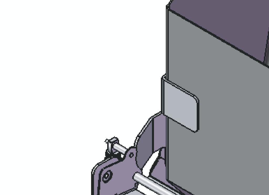
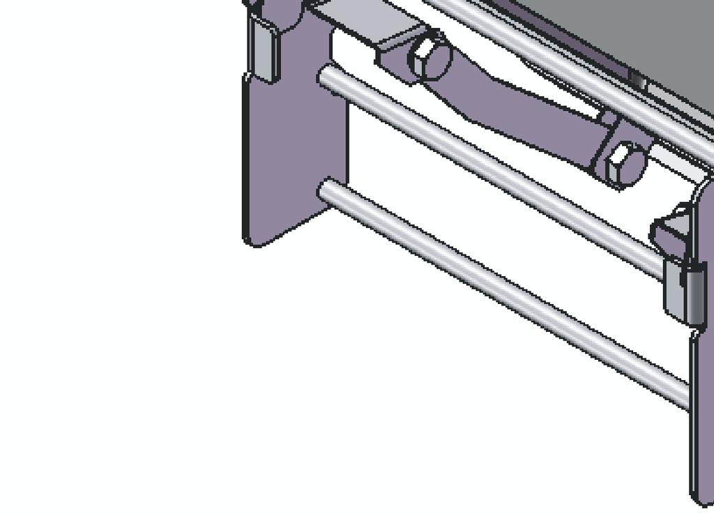
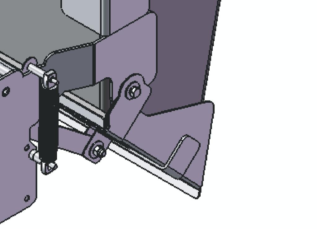
10 Rotary Actuator The Weigh Bucket is opened and closed by the Rotary Actuator. A stepper motor drive provides precise control by rotating a lever that actuates the linkage of the weigh bucket for opening and closing. The Rotary Actuator is located behind the Weigh Bucket component. The Rotary Actuator is shown in Figure 7. Figure 7 Rotary Actuator F7 6
11 Cutoff Gate As an available accessory, the Model VF100e can include an electrically-operated Cutoff Gate to restrict the flow of product during the dribble phase of a bulk and dribble filling application. When the bulk stage of the fill cycle completes, the solenoid of the Gate actuates to move the gate down to restrict product flow. A typical Cutoff Gate is shown in Figure 8. Figure 8 Cutoff Gate SOLENOID GATE MOUNTING ARM F8 Control Panel All major functions of the Model VF100e Vibratory Feeder are performed at the Control Panel. This panel includes a custom-programmed Touch Screen Panel that provides menus, selections, settings, and controls used to test, adjust, and operate the equipment, as well as switches and indicator lamps used in machine operation. A typical Model VF100e Control Panel is shown in Figure 9. A complete description of Control Panel use and operation is provided in a separate Touch Screen Control Panel Users Manual supplied with the complete set of documentation accompanying the equipment. 7

12 Figure 9 Model VF100e Control Panel TOUCH SCREEN PANEL EMERGENCY STOP EMERGENCY STOP SWITCH F9 Accessories The Model VF100e may include various accessories to be used in conjunction with the Vibratory Feeder. Flexible Product Gates Hopper Baffle Chute-Style Discharge Transition Bolt-On Nozzles and Chutes Installation and operating instructions for these type accessories will be provided separately and contained in the package of documentation supplied with the equipment. Tools & Materials The following tools and materials are used to install and maintain the ALL-FILL Model VF100e Vibratory Feeder and should be on hand prior to starting any installation work. Tools: - Screwdriver Set - Adjustable Wrenches - Allen Wrenches (assorted sizes) - Hoisting Equipment Additional tools may be required for electrical and/or pneumatic connections, depending on your specific type of filling machine and equipment. The hoisting equipment is used to position the filling machine. Consult shipping weight records for appropriate tonnage equipment. 8
13 Safety Considerations Use the following general guidelines and instructions with your ALL-FILL equipment to lessen the chance of accidents, personal injury, and damage to the machine and equipment. The Occupational Safety and Health Act (OSHA) places the burden of compliance of safe operation of equipment on the user of the equipment and the Act is generalized to the extent that determination of compliance is a judgment of the local inspector. ALL-FILL, Inc. is not responsible for meeting the full requirements of OSHA in respect to the equipment supplied, or for any penalty assessed for failure to meet the requirements of the Occupational Safety and Health Act, as interpreted by an authorized inspector. ALL-FILL, Inc. will use its best efforts to remedy any such violations at a reasonable cost to the buyer. Use proper lifting equipment to position the machine. Refer to shipping records for machine weight and select equipment accordingly. Position machine on stable, sound surface that will support the total weight plus any operators and additional equipment. Position the machine in relatively clean, dry areas with proper lighting and air circulation. Do not lift the unit by the trough. The feeder has been factory tuned for your specific application. Handling by the trough could cause damage to the feeder. Filling certain powder type products can create a possible dust explosion hazard. Be aware of potential sources of ignition and combustion and protect accordingly. Electrical connections should comply with accepted industry practices, local regulations, and established electrical codes. All Installation work is to be performed with electric power DISCONNECTED from the machine. Power can be reconnected after the work is completed for testing. Consider the use of safety glasses, hard hat, hearing protection, and other protective clothing for machine operators according to the environment, product, and general operating conditions. All safety guards are to be in place and in position during operation. Moving parts of the machine may present a cutting/snagging hazard when in use. Do not attempt adjustment when electrical power is connected to the machine. Never put hands or foreign objects into hopper during operation, even if the machine is not currently filling. Alert surrounding personnel when machine is in automatic mode. Do Not reach into machine to clear product or container jams when filling. Disconnect Electrical Power when installing, removing, or adjusting accessories. Disconnect Electrical Power prior to performing any maintenance on the machine. Do Not Overlubricate. Oil and grease attract product, dust, and dirt and will increase wear of moving parts. 9
14 Warranty Information ALL-FILL, Inc. warrants each new item of its manufacture to be free from defects for a period of one year from date of shipment. Used or reconditioned equipment will be warranted for a period of ninety (90) days from date of shipment. Equipment within this warranty will be repaired free of charge and returned to the point of original sale provided that: Prior approval is obtained from ALL-FILL, Inc. The defective equipment is returned freight pre-paid The equipment has not been damaged by misuse, neglect, improper operation, accident, or alteration; as determined by the seller Except for warranties and agreements expressly set forth in writing, ALL-FILL shall not be liable for any representation or warranty of any kind whatsoever, either expressed or implied. ALL-FILL assumes no responsibility or liability for any incidental or consequential damages caused by failure of any of its products or accessories. For additional information concerning your warranty rights and obligations, refer to the ALL- FILL, Inc. Standard Terms and Conditions supplied with the shipping documents. Additional Information Additional sources of information about your Model VF100e are contained in the corresponding Supplements, Drawings, Bill of Material information, and other custom information supplied with the equipment. 10
15 INSTALLATION This section contains information, procedures, and recommendations concerning the installation of your ALL-FILL Model VF100e Feeder. Included are the following: Inspection and Unpacking Site Requirements Installing the Equipment For use when you initially receive your machine from ALL-FILL That can be used to plan for the proper location to install and operate your Filling Machine Containing information about positioning the Feeder and making the necessary electrical & pneumatic connections When the Feeder is completely installed and tested, you can use the controls of the machine to begin filling production. Refer to the User s Manual that comes with your documentation package accompanying the equipment for instructions on how to use the controls. 11
16 Inspection and Unpacking Upon receipt of your ALL-FILL Model VF100e Feeder, you should initially inspect the shipping container(s) for any damage that may have occurred in transit. If damage is apparent, notify the transport carrier in writing immediately describing the damage. ALL-FILL should also be notified about any damage that may have occurred in shipping. ICC Regulations stipulate that a claim for damage must be submitted within 7 days of receipt. If the shipping container(s) does not appear damaged, you can begin to unpack the machine and any accessories. A Packing List is included with your shipment that details each item you are to receive.!!! IMPORTANT!!! Make sure you save the Packing List after unpacking and installation. The Packing List is necessary if you need to order replacement parts or if you receive an incomplete shipment. Refer to the section entitled Return Procedures in this manual concerning replacement of missing, damaged, or spare parts. The ALL-FILL Model VF100e Feeder arrives at your location with all major components preassembled, tested, and, if required, calibrated. Accessories that may have been ordered with your specific machine are packed separately and must be installed by the user. Be sure to unpack any accessories and set aside for subsequent installation. The Packing List can be used to check that you have received all Accessories ordered. Site Requirements Prior to installing and operating the Filling Machine, an area should be selected that fulfills the needed environmental, electric, pneumatic, and product supply requirements of a specific filling machine. The following lists the general site requirements recommended for ALL- FILL Filling Machines. Environmental Requirements The Filling Machine has been designed to operate in a variety of industrial environments without special equipment or additional maintenance. The general operating environment recommended for most applications is: Temperature: 32 to 122 F (0 to 50 C) Humidity: 5% to 100% relative humidity, noncondensing Other environmental conditions may be present (e.g., dust, hazardous fumes) that may affect operation and use of the filling machine. Contact ALL-FILL concerning recommendations about locating a filling machine in a nonstandard environment. 12
17 Electrical Requirements The installation site should be prewired for proper electrical power to the machine prior to installation. Typically, voltage, phase, & frequency are customer specified upon purchase of the machine. These electrical requirements are listed on a tag attached to the machine, and on the wiring diagram supplied with the machine. Consult this information to determine the electrical requirements at your site. As standard, the Model VF100e can be selected with the following power characteristics: 120v, single phase, 60 Hz. 220v, single phase, 60 Hz. Pneumatic Requirements The Model VF100e does not require compressed air, however, certain accessories and options (e.g., conveyor indexing, plungers, etc.) may be required If pneumatically-operated equipment is used with the Model VF100e, the installation site should include a source of compressed air before installing or operating the Model VF100e. Product Supply Requirements A consistent, reliable source of product to be available to refill the hopper of the filler is crucial to accuracy and overall operation of the machine. Before starting any installation, the site should be evaluated in terms of the availability of product re-supply to the hopper. Product should be supplied to be within 2-3 of the top of the hopper to maintain proper pressure. Product may be either flood-fed into the hopper, or periodically re-supplied by means of other equipment. ALL-FILL offers a wide variety of options to ensure a consistent source of product re-supply, including hopper-mounted Level Controls, Horizontal & Inclined screwfeeders, etc., depending on the site, product, and accuracy levels required. 13
18 Installing the Model VF100e Feeder Correct and careful installation of the ALL-FILL Model VF100e Feeder will result in proper, accurate filling production, lower maintenance, and reduced risk of machine downtime due to equipment failure. Installation is performed in the following, general sequence: Positioning the Filling Machine Connecting Electrical Power The following provide the installation information and procedures to perform each of these activities. Positioning the Model VF100e The machine should be located on a stable, level surface that includes the necessary environmental, electrical, pneumatic, and product supply requirements (see Site Requirements ). The machine should be placed in the upright, operating position using a forklift or power assisted hoisting equipment. Refer to the machine weight listed in the shipping records to select the corresponding lifting equipment. Be careful to avoid damaging machine components and equipment (especially sheet metal parts) when lifting into position. When in position, level the machine as required and secure to the floor using lag bolts through the base; or, if equipped with casters, firmly lock the casters in place to avoid unneeded movement. Inspect the parts of the machine, especially those attached with bolts and/or screws that may have vibrated loose during shipping. If hardware or equipment seems to be missing, check the Packing List and contact ALL-FILL should replacements be necessary. Electrical Connections When the machine is properly positioned and secured, the site electrical service can be connected and the machine initially operated to check for correct operation. All electrical installation should be performed by qualified personnel and done in accordance with all local codes and requirements. Electrical connections are listed on a custom wiring diagram that is supplied with the machine. Electrical specifications are also listed on a nameplate attached to the machine. Use this information to correctly connect electrical service to the Model VF100e Feeder. When electrical installation and connection is complete, power should be turned on to verify operation. Pneumatic Connections Pneumatic operated accessories and options used with the Model VF100e must be connected to a suitable source of compressed air at the site during installation. Connect a filtered, dried source of compressed air to the 1/4 NPT fitting at the machine. 14
19 Checkout and Operation When the machine and any accessories have been installed and connected, the controls of the machine can be used to begin filling production. Descriptions, instructions, and operating procedures for the controls are provided in a separate Users Manual. The corresponding Users Manual for your specific machine is contained in the package of documentation accompanying your machine. Refer to this manual for information to correctly setup and operate your machine for production. 15
20 16
21 SERVICE This section presents the general servicing instructions, procedures, and recommendations for your ALL-FILL Model VF100e Vibratory Feeder. Included are: Preventative Maintenance Troubleshooting Service Procedures Detailing the activities and recommended frequency of what to do to keep your machine in efficient, accurate operation. How to locate and identify problems with the machine, including Return and Repair Procedures and Recommended Spare Parts Presenting the most common procedures encountered for maintaining your Model VF100e Feeder in proper operating condition 17
22 Preventative Maintenance Following a regular pattern of daily and monthly preventative maintenance will assure continued, reliable operation of your ALL-FILL Feeder. Establishing procedures to perform maintenance will assist you in keeping your filling equipment in proper operating condition, as well as allowing you to recognize potential problems that could lead to a machine breakdown. In addition to your daily or production shift procedures of Startup, Shutdown, etc., you should design a program of daily and monthly maintenance that include activities listed in the following. Daily Maintenance The following should be checked on a daily basis after production shutdown or before startup for the Model VF100e Feeder. Make sure ALL electrical power is disconnected before attempting this procedure. Inspect all electrical connections for loose or frayed wires that may cause a short circuit. Re-connect correctly as required. Check to see that the controller is operating properly. If necessary, re-connect electrical power and turn the controller on to check operation. Clean any accumulated product buildup, dirt, moisture, etc., from all outside surfaces using a clean, dry cloth. Remove any loose tools or parts from around the machine. If machine includes guards, ensure that all are properly positioned to avoid damage or injury.!!! IMPORTANT!!! DO NOT OVER LUBRICATE. The machine may be operating in a dust filled environment due to the nature of the product. Over lubrication will cause dust and particles to stick to greasy and oiled surfaces. This combination will cause excessive wear of moving parts of the machine. Troubleshooting Failure of the machine to operate properly can often be quickly diagnosed in the field and corrected without the need for costly, time consuming repairs or spare parts. The following Table presents a cause/effect listing that can be used to identify and correct some of the more common problems that may occur with your machine. If a problem cannot be resolved using the troubleshooting methods below, refer to the Return/Repair Procedures at the end of this section for information about getting your machine repaired. 18
23 Table I Model VF100e Troubleshooting Problem Cause Correction Feeder operates too slow Line voltage below designated rating Increase line voltage as designated on the nameplate Unit in contact with rigid object/surface Maintain proper clearances Spring action may be hampered Defective leaf springs Worn or cracked trough Clean spring assemblies Replace Replace Line voltage above rating High voltage causes striking Reduce line voltage as designated on the nameplate Unit hums, will not vibrate Defective SCR within controller Replace Unit fails to operate No power to controller Check for broken or grounded lines Defective switch or fuse Defective SCR within controller Feeder coil burned out or grounded Short circuit in wiring Open winding on rheostat Replace Replace Replace Repair Replace 19
24 Return and Repair Procedures ALL-FILL can repair or replace failed equipment and components of filling machines when accompanied by a factory supplied Returned Goods authorization number. Components and equipment of ALL-FILL Filling Machines still covered under warranty will be repaired or replaced under the terms of ALL-FILL s standard 90 day warranty (see Warranty Information ). Items no longer under warranty will be repaired or replaced according to the standard Terms and Conditions supplied with the machine at the time of purchase. Refer to the Standard Terms and Conditions for additional information concerning the return, repair, and replacement of machine equipment and components. Spare Parts ALL-FILL offers pre-packaged Spare Part kits with the most commonly replaced items of the filling machine, based on the general type of filling machine. Additionally, a complete Bill of Material with all parts and assemblies is supplied with the relevant assembly drawings, separately with each machine. These can be used to identify and specify spare and/or replacement parts. Additionally, a Parts Diagram and Parts List for the Product Feeder are contained in the Appendix. Use this information to identify and locate spare parts for the Product Feeder components. Service Procedures The servicing guidelines provided in this section are for reference only. Actual servicing activities, schedules, and procedures depend on your specific machine, filling application, and typical plant operating requirements. Should you have a particular servicing or maintenance question or concern, contact your ALL-FILL, Inc. representative for additional information. Replacing Leaf Springs Replacement springs must be of the same size and thickness as those removed. The manufacturer recommends replacing all springs rather than just one. Before replacing springs, disconnect the feeder from the power supply. Work on one spring assembly at a time (first the rear spring stack). Make a note of the location and arrangement of each spring, spacer and clamp. Remove the bolts which secure the leaf springs to the base, then the bolts which hold the springs to the trough mounting bracket. Install the new spring assembly in reverse order of that removed. Replace cap screws and torque as specified in the following. Cap Screw Torque In/lb. Nm Dry Lubricated * * Plated fasteners considered lubricated 20
25 Adjusting Air Gap The air gap is the spacing that exists between the faces of the armature and core assemblies. Proper adjustment of this space is extremely important for good feeder operation. If the air gap is adjusted so the armature and core are too close, the faces of these items will make contact during feeder operation. This is called striking.!!! IMPORTANT!!! If a loud striking noise occurs, immediately turn the unit off. When operating normally, the feeder should perform with a smooth even stroke. If the air gap is adjusted so the armature and core are too far apart, the feeder current may increase to a dangerous level. A high current condition will result in coil burn-out, failure of control components or a reduced material feed rate. The air gap is set at the factory and re-adjustment should not be required. If high voltage is applied to the feeder, however, or if the air gap has been altered due to improper handling an adjustment may be necessary. Use the following to re-adjust the Air Gap. Air Gap adjustments are illustrated in Figure 10. Figure 10 Air Gap Adjustments CORE HEX HEAD NUT WIDENS GAP NARROWS GAP F10 21
26 Loosen the hex nut and insert a screwdriver into the slot on the end of the core. 2. Turn the core clockwise to narrow the air gap; or counterclockwise to widen the air gap. The proper air gap is reached when the air gap is as narrow as possible without striking condition. 3. The designated current rating must not be exceeded. 4. When the proper air gap has been obtained, lock the core in place by tightening the hex nut. The air gap adjustment is a very delicate procedure and may require some time to properly obtain the desired setting. The correct air gap spacing will be obtained when the armature and core faces are as close as possible without striking when maximum current is applied to the feeder magnet. Use a meter to measure feeder current. If using an analog clamp-on meter, the meter reading must always be multiplied by a value of 1.7 due to the wave characteristics of the feeder when operating. When using a true RMS meter, the current is as indicated. All current readings must be taken at the control. Measuring Stroke Units operate with the trough stroke between.045 to.050 (1.1 to 1.3 mm). This is checked from placing the stroke gauge on the trough assembly. Feeder stroke is the distance the trough travels in one complete cycle of vibration. This is measured from the forward upward limit of the vibrating stroke to the downward backward limit of the vibrating stroke. This stroke can be measured by applying a stroke gauge to the feeder trough. Be certain the graduated lines on the gauge are parallel with the line of drive. The gauge can be applied at any point on the side of the trough, as close to the centerline of the drive as possible. Under vibration, a black V will appear on the gauge. The amplitude of the unit can be read at the apex of this black V. The lines should appear solid black; if fuzzy and gray, the graduated lines of the gauge are not parallel to the line of the drive Figure 11 Stroke Gauge Positioning The Appendix contains a sample Stroke Gauge that can be used with your feeder. Remove the page from the manual, photocopy the stroke gauge and remove. Position on trough as indicated in Figure 11. FEEDER STROKE FEEDER STROKE
27 APPENDIX Stroke Gauge 23
28 24
29 Stroke Gauge CUT HERE CUT HERE CUT HERE CUT HERE CUT HERE FEEDER STROKE CUT HERE CUT HERE CUT HERE 25
30 26
31 INDEX Accessories, 8 Additional Information, 10 Adjusting Air Gap, 21 APPENDIX, 23 Checkout and Operation, 15 Components and Equipment, 2 Control Panel, 7 Cutoff Gate, 7 Daily Maintenance, 18 Discharge Transition, 3 Electrical Connections, 14 Electrical Requirements, 13 Environmental Requirements, 12 Figure 1 Model VF100e Vibratory Feeder, 1 Figure 2 Model VF100e Feeder Components, 2 Figure 3 Model VF100e Hopper, 3 Figure 4 Discharge Transition, 3 Figure 5 Product Feeder Components, 4 Figure 6 Weigh Bucket Components, 5 Figure 7 Rotary Actuator, 6 Figure 8 Cutoff Gate, 7 Figure 9 Model VF100e Control Panel, 8 Figure 10 Air Gap Adjustments, 21 Figure 11 Stroke Gauge Positioning, 22 Infeed Hopper, 3 Inspection and Unpacking, 12 INSTALLATION, 11 Installing the Model VF100e Feeder, 14 INTRODUCTION, 1 Measuring Stroke, 22 Model VF100e Vibratory Feeder, 1 Pneumatic Connections, 14 Pneumatic Requirements, 13 Positioning the Model VF100e, 14 Preventative Maintenance, 18 Product Feeder, 4 Product Supply Requirements, 13 Replacing Leaf Springs, 20 Return and Repair Procedures, 20 Rotary Actuator, 6 Safety Considerations, 9 SERVICE, 17 Service Procedures, 20 Site Requirements, 12 Spare Parts, 20 Stroke Gauge, 25 Table I Model VF100e Troubleshooting, 19 Tools & Materials, 8 Troubleshooting, 18 Warranty Information, 10 Weigh Bucket, 4 27
32 28
Service Instructions. Syntron Light-Capacity Electromagnetic Model: F-T01-A DF-T01-A
 Service Instructions Syntron Light-Capacity Electromagnetic Model: F-T01-A DF-T01-A Service Instructions Syntron Light-Capacity Electromagnetic Vibrating Feeders Models: F-T01-A and DF-T01-A Contents Page
Service Instructions. Syntron Electromagnetic Feeder Model: F-010-B DF-010-B
 Service Instructions Syntron Electromagnetic Feeder Model: F-010-B DF-010-B Service Manual Syntron Electromagnetic Feeder Models: F-010-B and DF-010-B Installation Operation Maintenance 1 Table of Contents
Service Instructions. Syntron Vibrating Feeder Model: F-010-BM
 Service Instructions Syntron Vibrating Feeder Model: F-010-BM SERVICE INSTRUCTIONS Syntron Vibrating Feeder Model: F-010-BM CONTENTS PAGE Introduction 1 Theory of Operation.. 2 Long-Term Storage. 3 Installation..
Service Instructions. Syntron Vibrating Feeder Model: RS-A Velocity TM
 Service Instructions Syntron Vibrating Feeder Model: RS-A Velocity TM Service Manual Syntron Vibrating Feeder Model: RS-A Velocity TM 1 Table of Contents GENERAL Page Safety Instructions 3 Introduction
Syntron EB-00 Vibratory Parts Feeder GENERAL MANUAL
 Syntron EB-00 Vibratory Parts Feeder GENERAL MANUAL INSTALLATION OPERATION MAINTENANCE Thank you for buying your equipment from Homer City Automation Inc. This manual will help you to understand how your
RENA AF371Feeder Operating Manual. Feeder. Operating Manual. Manual Part #: M AF371 Operations Rev
 Manual Part #: M-3022 Feeder AF371 Operations Rev. 3-16-04 1 RENA AF371 Feeder YOUR RENA AF371 IS DISTRIBUTED BY RENA SYSTEMS INC. SERVICE AND SUPPORT FOR THIS PRODUCT IS PROVIDED BY YOUR RENA DEALER.
Service Instructions. Syntron Heavy Duty Electromagnetic Vibratory Feeders Models: F-22, FH-22, and F-88
 Service Instructions Syntron Heavy Duty Electromagnetic Vibratory Feeders Models: F-22, FH-22, and F-88 Service Instructions Syntron Heavy Duty Electromagnetic Vibrating Feeders Model: F-22, FH-22, and
CRD610 Automatic Fitting Inserter
 CRD610 Automatic Fitting Inserter OPERATIONS MANUAL VERSION 1.2 LAST EDITED 12.12.2018 cleanroomdevices.com 1 Table of Contents Title Page. 1 Table of Contents...2 1.0 General Product & Safety Information....3
CRD600 Automatic Fitting Inserter
 CRD600 Automatic Fitting Inserter OPERATIONS MANUAL VERSION 2.3 LAST EDITED 12.07.2018 cleanroomdevices.com 1 Table of Contents Title Page.. 1 Table of Contents. 2 1.0 General Product & Safety Information...3
CLEAN ROOM DEVICES, LLC "WHERE TUBING AND FITTINGS COME TOGETHER"
 CLEAN ROOM DEVICES, LLC "WHERE TUBING AND FITTINGS COME TOGETHER" CRD600AF Automatic Fitting Inserter With Auto Feed OPERATIONS MANUAL (Shown with optional alcohol dispenser) 1 VERSION 1.1 LAST EDITED
NOTE: Local safety codes and regulations must be considered when installing and/or operating this unit.
 Syntron Vibratory Parts Feeder Model: Legacy UM-15 SAFETY INSTALLATION OPERATION Parts Feeder Drive Features and Benefits Spring Replacement Parts List Specifications Thank you for buying equipment from
CLEAN ROOM DEVICES, LLC "WHERE TUBING AND FITTINGS COME TOGETHER"
 CLEAN ROOM DEVICES, LLC "WHERE TUBING AND FITTINGS COME TOGETHER" CRD600 Automatic Fitting Inserter OPERATIONS MANUAL VERSION 2.1 LAST EDITED 7.25.14 DOCUMENT NUMBER 001 cleanroomdevices.com 1 Table of
Syntron F-450-C Electromagnetic Vibratory Feeder
 Syntron F-450-C Electromagnetic Vibratory Feeder SPRING REPLACEMENT COIL AND/OR CORE REPLACEMENT OPERATION PARTS LIST Thank you for buying your equipment from FMC. This manual will help you to understand
Installation and Parts Manual for SPANCO E Series Gantry Cranes
 Manual No. 103-0004 REV. 1/10 Installation and Parts Manual for SPANCO E Series Gantry Cranes ISO 9001 REGISTERED SPANCO, Inc. TABLE OF CONTENTS Warnings... 3 Assembly Instructions... 4 Serial Number Location...
FD Conveyor for FD 260 Tabber
 FD 260-20 Conveyor for FD 260 Tabber Operator Manual 1/2011 First Edition TABLE OF CONTENTS 1. INTRODUCTION... 1 1.1 FD 260-20 DESCRIPTION... 1 1.2 ITEMS INCLUDED... 1 1.3 OPERATING MANUAL SAFETY TERMS...
Owner s Manual & Safety Instructions
 Owner s Manual & Safety Instructions Save Save This This Manual Keep Keep this this manual manual for for the the safety safety warnings warnings and and precautions, assembly, assembly, operating, inspection,
Effective June 1, 2013 This guide supersedes all previous versions
 Effective June 1, 2013 This guide supersedes all previous versions 3842 Redman Drive 1-800-797-7974 Fort Collins, CO 80524 www.commandlight.com L-CAS THANK YOU Please allow us to express a simple thank
Tooling Assistance Center
 Safeguards are designed into this application equipment to protect operators and maintenance personnel from most hazards during equipment operation. However, certain safety precautions must be taken by
ELECTROMAGNETIC VIBRATORY FEEDER INSTRUCTION AND MAINTENANCE MANUAL
 ELECTROMAGNETIC VIBRATORY FEEDER INSTRUCTION AND MAINTENANCE MANUAL INDEX 1.0 Introduction Page 3 2.0 Location Page 3 3.0 Controller Page 3 4.0 Maintenance Page 3 5.0 Coil Removal Page 3 6.0 Spring removal
Angle Grinder Holder
 Angle Grinder Holder Owner s Manual WARNING: Read carefully and understand all ASSEMBLY AND OPERATION INSTRUCTIONS before operating. Failure to follow the safety rules and other basic safety precautions
Heavy Duty Engine Cranes
 Heavy Duty Engine Cranes Operating Instructions & Parts Manual Model Number Atd-7484 Atd-7485 (Foldable Legs) Capacity 2 Ton 2 Ton Model Atd-7484 Model Atd-7485 Atd Tools Inc. 160 Enterprise Drive, Wentzville,
Manual Operated Floor Jack
 Manual Operated Floor Jack OPERATING INSTRUCTIONS Note: There may be some slight differences in the appearance of the various manually-operated floor jacks, however the instructions in this manual apply
Installation and Parts Manual for SPANCO A Series Steel Gantry Cranes
 Manual No. 103-0002 08/14 Installation and Parts Manual for SPANCO A Series Steel Gantry Cranes ISO 9001 REGISTERED 2 TABLE OF CONTENTS Warnings... 3 Assembly and Operation...4 Track Installation Instructions...6
Adjustable Angled Incline Conveyor Owners Manual with Operating Instructions
 Adjustable Angled Incline Conveyor Owners Manual with Operating Instructions Revision 012211 Table of Contents Basic Conveyor Features 3 Getting Started 4 Setting Up the Incline Conveyor 5 Belt Removal
60 Series End-Mount Brake Instructions Standard Housing
 Bulletin No. BK4655 (04/18) 60 Series End-Mount Brake Instructions Standard Housing Read carefully before attempting to assemble, install, operate or maintain the product described. Protect yourself and
1250 LB. CAPACITY MECHANICAL WHEEL DOLLY
 1250 LB. CAPACITY MECHANICAL WHEEL DOLLY 67287 SET-UP AND OPERATING INSTRUCTIONS Visit our website at: http://www.harborfreight.com Read this material before using this product. Failure to do so can result
Service Instructions. DL-1-A Dental Vibrator
 Service Instructions DL-1-A Dental Vibrator Syntron DL-1-A Dental Vibrator Installation Operation Maintenance 1 Thank you for buying your equipment from SMH. This manual will help you to understand how
TABLE OF CONTENTS. Warranty Disclaimers Delivery Checklist After Sale Checklist Safety Set Up... 8
 TABLE OF CONTENTS Pickett Equipment Warranty... 2 Warranty Disclaimers... 3 Delivery Checklist... 4 After Sale Checklist... 4 Safety... 5-7 Set Up... 8 Machine Adjustments and Operation... 9 Maintenance
SSLS & SSLS4-27 Series Lift Tables
 Owner s Manual SSLS2.5-27 & SSLS4-27 Series Lift Tables Southworth Products Corp P.O. Box 1380, Portland, Maine 04104-1380 Phone: 800-743-1000 / 207-878-0700 Fax: 207-797-4734 www.southworthproducts.com
RED23305 Owner s Manual
 RED23305 Owner s Manual 5 foot, 3-Point Mounted Snow Blower 270 West Park Avenue Huron, SD 57350 866-526-5682 Serial Number: Date of Purchase: Red Devil Snow Blower See Figure 1. 1. The Red Devil Snow
Jet Fans. Instruction Manual READ AND SAVE THESE INSTRUCTIONS WARRANTY
 Jet Fans Instruction Manual READ AND SAVE THESE INSTRUCTIONS WARRANTY All Leader Fan products are guaranteed to be free from defects of workmanship or material and to function satisfactorily when properly
BC Brake Caliper. (i) MEX (55) QRO (442) MTY (81) DIST. AUTORIZADO
 MEX (55) QRO (442) MTY (81) DIST. AUTORIZADO") MEX (55) 5 6 QRO (44) 95 7 60 MTY () 54 0 BC Brake Caliper (i) FORM NO. L-0066-B-040 In accordance with Nexen s established policy of constant product improvement, the specifications contained in this
MEX (55) 5 6 QRO (44) 95 7 60 MTY () 54 0 BC Brake Caliper (i) FORM NO. L-0066-B-040 In accordance with Nexen s established policy of constant product improvement, the specifications contained in this
p.t.o. Slip clutch Read this material before using this product. Failure to do so can result in serious injury. Save this manual.
 p.t.o. Slip clutch 65517 Installation Instructions Distributed exclusively by Harbor Freight Tools. 3491 Mission Oaks Blvd., Camarillo, CA 93011 Visit our website at: http://www.harborfreight.com Read
McCANNA Actuation Systems B
 17710-B Ramcon Series 8/25 C/CR, 50/100 B/BR, 250/500 B/BR Electric Actuators Installation, Operation and Maintenance Instructions Contents Storage...........................................................................................................
Hydraulic Wheel Dolly
 Hydraulic Wheel Dolly Operating Instructions & Parts Manual Model Number HW93765 Capacity 3/4 Ton Made in the U.S.A. This is the safety alert symbol. It is used to alert you to potential personal injury
CTFRP Series Power Supplies
 CTFRP Series Power Supplies Ferroresonant Non-Standby Power Supplies User Manual Myers Power Products 6/2013 CTFRP Series Manual Chapter 1 General Information The Myers CTFRP Series Power Supply provides
Auto-Reamer. 2100E2 Nozzle Cleaning Station. Operating Manual and Parts List. January 2018 v18.1
 Auto-Reamer 2100E2 Nozzle Cleaning Station Operating Manual and Parts List 2100E2 w/ WC-95E DO NOT INSTALL, OPERATE, OR REPAIR THIS EQUIPMENT WITHOUT READING THIS OPERATING MANUAL MADE IN USA January 2018
Transmission Jacks. 1ZKY1 and 1ZKY3. Description. Specifications. Assembly
 Operating Instructions & Parts Manual Please read and save these instructions. Read carefully before attempting to assemble, install, operate or maintain the product described. Protect yourself and others
RF6 / RF10 / RF18 Installation Instructions
 RF6 / RF10 / RF18 Installation Instructions Thank you very much for purchasing PIAA product. Read this instruction manual thoroughly for proper use of the product. After completing your installation, please
PHANTOM (PH10 and PH12) COMMERCIAL AND INDUSTRIAL SERIES
 COMMERCIAL AND INDUSTRIAL SERIES") Document No: ICM-IOM Date: 0411 PHANTOM (PH10 and PH12) COMMERCIAL AND INDUSTRIAL SERIES Installation, Operation and Maintenance Manual Please read and save these instructions. Read carefully before attempting
Document No: ICM-IOM Date: 0411 PHANTOM (PH10 and PH12) COMMERCIAL AND INDUSTRIAL SERIES Installation, Operation and Maintenance Manual Please read and save these instructions. Read carefully before attempting
COMPRESSED AIR LOADER MODEL: AL-1
 COMPRESSED AIR LOADER MODEL: AL-1 Document: AL-1 IM 10-22-2011 TABLE OF CONTENTS Important Notices and Precautions 3 Quick Installation 4 Product Description 4 Principle of Operation 5 Unpacking and Inspection
Installation and Parts Manual for SPANCO A Series Steel Gantry Cranes
 Manual No. 103-0002 REV. 3/07 Installation and Parts Manual for SPANCO A Series Steel Gantry Cranes ISO 9001 REGISTERED 2 TABLE OF CONTENTS Warnings... 3 Assembly and Operation...4 Track Installation Instructions...6
Universal Bevel Drives Service Manual
 Engineering Service Bulletin #SB241202 Universal Bevel Drives Service Manual Cautions Following are some general cautions. All personnel shall use safe and sound practices and take all necessary precautionary
Operating Instructions & Parts Manual. Supa-Lite Lever Grease Gun. Model 48UJ77
 Operating Instructions & Parts Manual EN Supa-Lite Lever Grease Gun Model 48UJ77 PLEASE READ AND SAVE THESE INSTRUCTIONS. READ CAREFULLY BEFORE ATTEMPTING TO ASSEMBLE, INSTALL, OPERATE OR MAINTAIN THE
25 GALLON PORTABLE OIL LIFT
 25 GALLON PORTABLE OIL LIFT Model 92859 SET UP AND OPERATING INSTRUCTIONS Diagrams within this manual may not be drawn proportionally. Due to continuing improvements, actual product may differ slightly
2020 Dual Tabber Operation Manual
 2020 Dual Tabber Operation Manual Revision 1.2 10 Clipper Road 10/24/2006 West Conshohocken, PA 19428-2721 Tel : 800-523-0320 / 610-825-6205 Fax: 610-825-1397 www.secap.com Index SECTION 1 Introduction
TSS Tool Stand. Installation and Operation Manual. Document #:
 TSS Tool Stand Installation and Operation Manual Document #: 9610-20-1068 Engineered Products for Robotic Productivity Pinnacle Park 1031 Goodworth Drive Apex, NC 27539 Tel: +1-919.772.0115 Fax: +1-919.772.8259
AIR CHAMP PRODUCTS. User Manual. Sheave & Pilot Mount Clutch-Brake Model BCB-275 FORM NO. L F-0414 FORM NO. L F-0414
 AIR CHAMP PRODUCTS User Manual Sheave & Pilot Mount Clutch-Brake Model BCB-275 i In accordance with Nexen s established policy of constant product improvement, the specifications contained in this manual
Service Instructions. Syntron Electromagnetic Feeder Model:BF-4-ALF and BF-4-ASLF (stainless steel hardware)
") Service Instructions Syntron Electromagnetic Feeder Model:BF-4-ALF and BF-4-ASLF (stainless steel hardware) Service Manual Syntron Electromagnetic Feeder Models: BF-4-ALF and BF-4-ASLF (stainless steel
Service Instructions Syntron Electromagnetic Feeder Model:BF-4-ALF and BF-4-ASLF (stainless steel hardware) Service Manual Syntron Electromagnetic Feeder Models: BF-4-ALF and BF-4-ASLF (stainless steel
Hydraulic Wheel Dolly
 Hydraulic Wheel Dolly Operating Instructions & Parts Manual Model Number HW93766 Capacity 3/4 Ton Made in the U.S.A. This is the safety alert symbol. It is used to alert you to potential personal injury
Service Instructions. Syntron Vibrating Feeders Model: FH-24-D-HP
 Service Instructions Syntron Vibrating Feeders Model: FH-24-D-HP SERVICE MANUAL Syntron Vibrating Feeders MODEL: FH-24-D-HP High Performance Vibratory Feeders 1 Table of Contents General Page Safety Instructions..
150-Lb. Drywall and Panel Hoist
 150-Lb. Drywall and Panel Hoist Owner s Manual WARNING: Read carefully and understand all ASSEMBLY AND OPERATION INSTRUCTIONS before operating. Failure to follow the safety rules and other basic safety
RolsplicerTM. Maintenance Manual And Illustrated Parts List
 RolsplicerTM Maintenance Manual And Illustrated Parts List List of Illustrations Figure Page. Rolsplicer 3 2. Roller Adjustment 4 3. Rolsplicer 6 4. Lid Hold Down Assembly 8 5. Automatic Lid Speed Adjustment
Installation and Maintenance Manual for SPANCO A Series Aluminum Gantry Cranes
 Manual No. 103-0008 REV. 6/11 Installation and Maintenance Manual for SPANCO A Series Aluminum Gantry Cranes ISO 9001 REGISTERED SPANCO, Inc. 2 TABLE OF CONTENTS Warnings... 3 Installation... 4 Maintenance...
INSTALLATION and OPERATION BALL WASHER MODEL NO: BW-001N
 Easy Picker Golf Products, Inc. 415 Leonard Blvd. N., Lehigh Acres, FL 33971 PH: 239-368-6600 FAX: 239-369-1579 Service: 800-982-4653 SALES: 800-641-4653 www.easypicker.com salesdept@easypicker.com INSTALLATION
Heavy-Duty Welding Fabrication Table
 Heavy-Duty Welding Fabrication Table with Fix-Up Kit Owner s Manual WARNING: Read carefully and understand all ASSEMBLY AND OPERATION INSTRUCTIONS before operating. Failure to follow the safety rules and
Service Instructions. Syntron Jogger Model: J-1-B
 Service Instructions Syntron Jogger Model: J-1-B Service Instructions Syntron Jogger Model: J-I-B Contents Page Introduction 1 Installation 2 Operation 2 Maintenance 2 Trouble Shooting 3 Parts List 4 Illustration
Adjustable Purge Valve
 U S E R G U I D E UGC031-0508 www.conairgroup.com Adjustable Purge Valve Single and Dual APV Models Corporate Office: 724.584.5500 l Instant Access 24/7 (Parts and Service): 800.458.1960 l Parts and Service:
CR193 Vacuum Limitamp* Contactors
 GE Electrical Distribution GEH-5306C Maintenance Instructions CR193 Vacuum Limitamp* Contactors Contents Section 1 Introduction... 3 General... 3 Section 2 Description... 4 Principle of Operation... 4
Low Profile Service Jack
 Low Profile Service Jack Operating Instructions & Parts Manual Model Number JSA200LCX Capacity 2 Ton MAC TOOLS INC. 2005 505 N. Cleveland Ave. Suite 200 Westerville, OH 43082 Printed in PRC Save these
Giant Hydraulic Disc Brake System
 Giant Hydraulic Disc Brake System INSTALLATION INSTRUCTI IMPORTANT NOTICE Contact the place of purchase or Authorized Giant Retailer for information on detail of installation and maintenance. Read this
Dayton DC Motor Control
 Operating Instructions & Parts Manual Please read and save these instructions. Read carefully before attempting to assemble, install, operate or maintain the product described. Protect yourself and others
Instruction Booklet for the Installation, Operation and Maintenance of Type 5-15 kv VCP-WG Vacuum Circuit Breaker 4000A MiniMod
 Instruction Booklet for the Installation, Operation and Maintenance of Type 5-15 kv VCP-WG Vacuum Circuit Breaker 4000A MiniMod Eaton Corporation Moon Twp, PA. U.S.A. 15108 1 INTRODUCTION READ AND UNDERSTAND
General Installation Instructions for Valves and Gates
 General Installation Instructions for Valves and Gates Thank you for your purchase of a Lorenz valve. We appreciate your business! Please read this installation manual and follow recommended safety precautions.
2 1/4 TON HYDRAULIC FLOOR JACK
 2 1/4 TON HYDRAULIC FLOOR JACK Item Number W1611 OWNER S MANUAL WARNING It is the owner and/or operators responsibility to study all WARNINGS, operating, and maintenance instructions contained on the product
DeZURIK 2 20" BOS BUTTERFLY VALVES
 2 20" BOS BUTTERFLY VALVES Instruction D10459 October 2013 2-20 BOS Butterfly Valves Instructions These instructions provide information about BOS Butterfly Valves. They are for use by personnel who are
PUSH BUTTON KEY CABINET
 PUSH BUTTON KEY CABINET Model 95689 INSTALLATION And Operation Instructions Due to continuing improvements, actual product may differ slightly from the product described herein. 3491 Mission Oaks Blvd.,
READ AND SAVE THESE INSTRUCTIONS. High Velocity Restaurant-Duty Utility Set Belt Driven for Roof Mounting
 READ AND SAVE THESE INSTRUCTIONS INSTALLATION, OPERATING INSTRUCTIONS & PARTS MANUAL High Velocity Restaurant-Duty Utility Set Belt Driven for Roof Mounting Electrical wiring and connections should be
2000-LB. ENGINE STAND
 2000-LB. ENGINE STAND WARNING: Read carefully and understand all ASSEMBLY AND OPERATION INSTRUCTIONS before operating. Failure to follow the safety rules and other basic safety precautions may result in
WINDGUARD BELT DRIVE (BD) INDUSTRIAL SERIES
 INDUSTRIAL SERIES") Document No: BD-IOM Date: 01/13/16 WINDGUARD BELT DRIVE (BD) INDUSTRIAL SERIES Installation, Operation and Maintenance Manual Please read and save these instructions. Read carefully before attempting to
Document No: BD-IOM Date: 01/13/16 WINDGUARD BELT DRIVE (BD) INDUSTRIAL SERIES Installation, Operation and Maintenance Manual Please read and save these instructions. Read carefully before attempting to
Raydot LLC 24 Actuator (115 VOLT)
") Installation, Operation & Parts Manual Read carefully the information provided. Retain manual for future reference. Raydot LLC 24 Actuator (115 VOLT) 145 Jackson Ave. S. Cokato, MN 55321-USA (320) 286-2103
Installation, Operation & Parts Manual Read carefully the information provided. Retain manual for future reference. Raydot LLC 24 Actuator (115 VOLT) 145 Jackson Ave. S. Cokato, MN 55321-USA (320) 286-2103
Single Post Caliper Brake VC500
 Single Post Caliper Brake VC500 1 In accordance with Nexen s established policy of constant product improvement, the specifications contained in this manual are subject to change without notice. Technical
APCO CRF-100A RUBBER FLAPPER SWING CHECK VALVES
 APCO CRF-100A RUBBER FLAPPER SWING CHECK VALVES Instruction D12043 June 2016 DeZURIK Instructions These instructions provide installation, operation and maintenance information for APCO CRF-100A Rubber
User s Manual and Operating Instructions
 User s Manual and Operating Instructions Model Numbers: CL-36-BDF-A, CL-42-BDF-A, CL-48-BDF-A E355088 READ AND SAVE THESE INSTRUCTIONS IMPORTANT: Read and understand all of the instructions in this manual
3000-Lb. Vehicle Positioning Jacks. Owner s Manual
 3000-Lb. Vehicle Positioning Jacks Owner s Manual WARNING: Read carefully and understand all ASSEMBLY AND OPERATION INSTRUCTIONS before operating. Failure to follow the safety rules and other basic safety
Power Float Manifold. Installation and Operations Manual Module 11A
 Power Float Manifold Installation and Operations Manual Module 11A 2/14 Table of Contents 1 Features 3 2 Functional Purpose 3 3 4 Specifications System Installation 3 4 4.1 Hydraulic Connection 4 4.2 Electric
OLYMPIAN MODEL 740 Operation and Service Manual
 OLYMPIAN MODEL 740 Operation and Service Manual P/N 133911-102 FCI MANUAL P/N 133865-001 Data herein has been verified and validated and believed adequate for the intended use. If the machine or procedures
Adjustable Steel Welding Table
 Adjustable Steel Welding Table Owner s Manual WARNING: Read carefully and understand all ASSEMBLY AND OPERATION INSTRUCTIONS before operating. Failure to follow the safety rules and other basic safety
SENTRY HAMMER MILL MODEL 130/1030 OPERATIONS / PARTS MANUAL
 SENTRY HAMMER MILL MODEL 130/1030 OPERATIONS / PARTS MANUAL 1 TABLE OF CONTENTS PAGE WARRANTY 2 BE A SAFE OPERATOR 3-6 FORWARD 7 PARTS ORDERING INFORMATION 8 INSTALLATION & INTRODUCTION 9 ELECTRICAL TROUBLESHOOTING
INSTALLATION AND OPERATION MANUAL Low Profile Long Frame Floor Jack Model: RFJ-3000LPF REV B
 PLEASE READ THE ENTIRE CONTENTS OF THIS MANUAL PRIOR TO INSTALLATION AND OPERATION. BY PROCEEDING YOU AGREE THAT YOU FULLY UNDERSTAND AND COMPREHEND THE FULL CONTENTS OF THIS MANUAL. FORWARD THIS MANUAL
DeZURIK 2-24 (50-600mm) KGN-RSB BI-DIRECTIONAL CAST STAINLESS STEEL KNIFE GATE VALVES
 KGN-RSB BI-DIRECTIONAL CAST STAINLESS STEEL KNIFE GATE VALVES") 2-24 (50-600mm) KGN-RSB BI-DIRECTIONAL CAST STAINLESS STEEL KNIFE GATE VALVES Instruction D11023 October 2016 Instructions These instructions provide information about KGN-RSB Knife Gate Valves. They are
2-24 (50-600mm) KGN-RSB BI-DIRECTIONAL CAST STAINLESS STEEL KNIFE GATE VALVES Instruction D11023 October 2016 Instructions These instructions provide information about KGN-RSB Knife Gate Valves. They are
8 Light Controller. Instruction Manual. With Light Timer 240 Volts. Product # INNOVATING SINCE 1995
 8 Light Controller With Light Timer 240 Volts Product #703008 Instruction Manual INNOVATING SINCE 1995 1 www.titancontrols.net 8 Light Controller This manual covers the following: Warnings & Cautions 8
dv Sentry TM 208V 600V INSTALLATION GUIDE Quick Reference ❶ How to Install Pages 6 14 ❷ Startup/Troubleshooting Pages WARNING
 dv Sentry TM 208V 600V INSTALLATION GUIDE FORM: DVS-IG-E REL. January 2018 REV. 003 2018 MTE Corporation High Voltage! Only a qualified electrician can carry out the electrical installation of this filter.
DynaCon Instruction Manual
 DynaCon Instruction Manual Table of Contents Technical Specification & Warranty.... 3 Construction, Benefits & Safe Operating Procedures... 4 Noise Levels... 5 Installation, Operation & Maintenance...
Heavy Duty Four Wheeled Walker
 Heavy Duty Four Wheeled Walker Weight Capacity: 500 lbs. ITEM # W1802 Made in China 2011 ESSENTIAL MEDICAL SUPPLY, INC. Manufactured for Orlando, FL 32822 -- SAVE THESE INSTRUCTIONS -- Do not attempt to
Installation, Operation, and Maintenance Manual
 Industrial Process Installation, Operation, and Maintenance Manual Series PBV Plastic Lined Ball Valve Table of Contents Table of Contents Introduction and Safety...2 Safety message levels...2 User health
Hydraulic Transmission Jacks
 Hydraulic Transmission Jacks Operating Instructions & Parts Manual Model Number Atd-7435 Atd-7436 Atd-7437 Capacity 1100 Lb. 2000 Lb. 3000 Lb. Model Atd-7435 Model Atd-7436 Model Atd-7437 Atd Tools Inc.
"WHERE TUBING AND FITTINGS COME TOGETHER"
 CLEAN ROOM DEVICES, LLC "WHERE TUBING AND FITTINGS COME TOGETHER" CRD200SS TUBE EXPANDER OPERATIONS MANUAL VERSION 4.3 LAST EDITED 06.17.15 cleanroomdevices.com Table of Contents Table of Contents....1
Heavy-Duty Drywall Dolly Cart
 Heavy-Duty Drywall Dolly Cart Owner s Manual WARNING: Read carefully and understand all ASSEMBLY AND OPERATION INSTRUCTIONS before operating. Failure to follow the safety rules and other basic safety precautions
Benchmark HD Series Heavy Duty Bench Scale. Installation Manual
 Benchmark HD Series Heavy Duty Bench Scale Installation Manual 93631 Contents 1.0 Introduction... 1 1.1 Benchmark HD Specifications...................................................... 1 2.0 Installation...
NorthStar. brand. Instruction Manual. SLIM Tach SL Thru-Shaft Diameter. Magnetoresistive Encoder Designed for GE Wind Energy
 NorthStar TM brand Instruction Manual SLIM Tach SL56 1.125 Thru-Shaft Diameter Magnetoresistive Encoder Designed for GE Wind Energy Patent Pending *791-1061-00* Rev. B Page 2 Table of Contents Chapter/Paragraph/Illustration
Manual Operated Floor Jack
 Manual Operated Floor Jack OPERATING INSTRUCTIONS Note: There may be some slight differences in the appearance of the various manually-operated floor jacks, however the instructions in this manual apply
HSIV PLOW OPERATOR S MANUAL
 PLOW RWF INDUSTRIES 873 Devonshire Ave., Woodstock, Ontario N4S 8Z4 Tel: (519) 421-0036 Toll Free: 1-800-263-1060 Fax: (519) 421-0028 Email: parts@rwfbron.com JANUARY 2015 THE INFORMATION CONTAINED IN
1. Contents 1. CONTENTS INTRODUCTION SAFETY WARNINGS POWER TILT STANDARD OPERATING INSTRUCTIONS... 5.
 1. Contents 1. CONTENTS..... 2. INTRODUCTION..... 3. SAFETY WARNINGS..... 4. POWER TILT STANDARD OPERATING INSTRUCTIONS....... 5. POWER SEAT LIFT STANDARD OPERATING INSTRUCTIONS...... 6. POWER TILT / SEAT
Sawhorse with Chainsaw Holder
 Sawhorse with Chainsaw Holder Owner s Manual Chainsaw not included. WARNING: Read carefully and understand all ASSEMBLY AND OPERATION INSTRUCTIONS before operating. Failure to follow the safety rules and
3/4 Ton Heavy Duty Wheel Dolly
 3/4 Ton Heavy Duty Wheel Dolly Operating Instructions & Parts Manual BH8075 SFA Companies 2004 10939 N. Pomona Ave. Kansas City, MO 64153 816-891-6390 sales@blackhawk-automotive.com - Before using this
MODEL 660 AUTOMATIC FASTENING CENTER OPERATOR S MANUAL
 MODEL 660 AUTOMATIC FASTENING CENTER OPERATOR S MANUAL Copyright: January 13, 2003 Revised: 080612 Serial No. 0506113. 1 TABLE OF CONTENTS INTRODUCTION..3 OPERATOR SAFETY... 3 SYSTEM REQUIREMENTS..4 INSTALLATION
Universal Bench-top Conveyor OPERATOR S GUIDE
 OPERATOR S GUIDE DISCLAIMER LIABILITY LIMITATION: The Buyer of this product accepts full responsibility and understanding for the terms and specifications set forth herein. Con-Trol-Cure makes no claim,
Owner s Manual & Safety Instructions
 Owner s Manual & Safety Instructions Save This Manual Keep this manual for the safety warnings and precautions, assembly, operating, inspection, maintenance and cleaning procedures. Write the product s
INSTALLATION, OPERATION AND MAINTENANCE MANUAL WALL EXHAUST FANS BELT DRIVE XBL FANS
 INSTALLATION, OPERATION AND MAINTENANCE MANUAL WALL EXHAUST FANS BELT DRIVE XBL FANS The purpose of this manual is to aid in the proper installation and operation of the fans. These instructions are intended