R Y T E C. WyndStar MT. Installation & Owner s Manual
|
|
|
- Marylou Crawford
- 5 years ago
- Views:
Transcription

1 R Y T E C WyndStar MT Installation & Owner s Manual P.O. Box 403 One Cedar Parkway, Jackson, WI Phone: Fax: Rytec Website: Rytec On line store: Rytec E mail: helpdesk@rytecdoors.com, Parts E mail: Parts@rytecdoors.com [Revision: November 10 th, 2015, R , Rytec Corporation 2001]
2 WYND STAR MT LIMITED WARRANTY Rytec Corporation ( Seller ), an Illinois corporation with its principal place of business at One Cedar Parkway, PO Box 403, Jackson, WI 53037, warrants to the original registered end-user commercial purchaser ( Buyer ) that the Wynd Star MT ( Product ) sold to the Buyer will be free of defects in materials and workmanship (ordinary wear and tear excepted) for the time periods set forth below: Mechanical components for a period of One (1) Year from the date of shipment of the Product from the Seller s plant ( Shipment ). Electrical components for a period of One (1) Year from Shipment. Standard door panels, including Vinyl, for a period of One (1) Year from Shipment. Side column brush/vinyl seals, side column self-repair guides, side column wear strip, vinyl loop seal, vision panel sections are considered wear items and are not covered under this Limited Warranty. Aftermarket parts, accessories, and assemblies for a period of Ninety (90) Days from the date of Shipment. Remedies. Seller s obligation under this Limited Warranty is limited to repairing or replacing, at Seller s option, any part which is determined by Seller to be defective during the applicable warranty period. Such repair or replacement shall be the Seller s sole obligation and the Buyer s exclusive remedy under this Limited Warranty. Labor. Except in the case of aftermarket parts, accessories, and assemblies, labor is warranted for one year. This means that Seller will provide warranty service without charge for labor in the first year of the warranty period. Thereafter, a charge will apply in to any repair or replacement under this Limited Warranty. In the case of aftermarket parts, accessories, and assemblies, Seller will provide replacement parts only. Claims. Claims under this Limited Warranty must be made (i) within 30 (thirty) days after discovery and (ii) prior to expiration of the applicable warranty period. Claims shall be made in writing delivered to the Seller at the address provided in the first paragraph of this warranty. Buyer must allow Seller and Dealer, or their agents, a reasonable opportunity to inspect any Product claimed to be defective and shall, at Seller s option, either (x) grant Seller and Dealer or their agents access to Buyer s premises for the purpose of repairing or replacing the Product or (y) return of the Product to the Seller, f.o.b. Seller s factory. Original Buyer. This Limited Warranty is made to the original Buyer of the Product and is not assignable or transferable. This Limited Warranty shall not be altered or amended except in a written instrument signed by Buyer and Seller. Not Warranted. Seller does not warrant against and is not responsible for, and no implied warranty shall be deemed to cover, damages that result directly or indirectly from: (i) the unauthorized modification or repair of the Product, (ii) damage due to misuse, neglect, accident, failure to provide necessary maintenance, or normal wear and tear of the Product, (iii) failure to follow Seller s instructions for installation, operation or maintenance of the Product, (iv) use of the Product in a manner that is inconsistent with Seller s guidelines or local building codes, (v) movement, settling, distortion, or collapse of the ground, or of improvements to which the Products are affixed, (vi) fire, flood, earthquake, elements of nature or acts of God, riots, civil disorder, war, or any other cause beyond the reasonable control of Seller, (vii) improper handling, storage, abuse, or neglect of the Product by Buyer or by any third party.
3 DISCLAIMERS. THIS WARRANTY IS EXCLUSIVE AND IN LIEU OF ALL OTHER REPRESENTATIONS AND WARRANTIES, EXPRESS OR IMPLIED, AND THE SELLER EXPRESSLY DISCLAIMS AND EXCLUDES ANY IMPLIED WARRANTIES OF MERCHANTABILITY OR FITNESS FOR PURPOSE. SELLER SHALL NOT BE SUBJECT TO ANY OTHER OBLIGATIONS OR LIABILITIES, WHETHER ARISING OUT OF BREACH OF CONTRACT, WARRANTY, TORT (INCLUDING NEGLIGENCE AND STRICT LIABILITY) OR OTHER THEORIES OF LAW, WITH RESPECT TO THE PRODUCTS SOLD OR SERVICES RENDERED BY THE SELLER, OR ANY UNDERTAKINGS, ACTS, OR OMISSIONS RELATING THERETO. LIMITATION OF LIABILITY. IN NO EVENT WILL SELLER BE RESPONSIBLE FOR, OR LIABLE TO ANYONE FOR, SPECIAL, INDIRECT, COLLATERAL, PUNITIVE, INCIDENTAL, OR CONSEQUENTIAL DAMAGES, EVEN IF SELLER HAS BEEN ADVISED OF THE POSSIBILITY OF SUCH DAMAGES. Such excluded damages include, but are not limited to, personal injury, damage to property, loss of goodwill, loss of profits, loss of use, cost of cover with any substitute product, interruption of business, or other similar indirect financial loss. Product Descriptions. Any description of the Products, whether in writing or made orally by the Seller or the Seller s agents, including specifications, samples, models, bulletins, drawings, diagrams, engineering or similar materials used in connection with the Buyer s order, are for the sole purpose of identifying the Product and shall not be construed as an express warranty. Any suggestions by the Seller or the Seller s agents regarding the use, application, or suitability of the Product shall not be construed as an express warranty unless confirmed to be such in writing by the Seller. Limited Warranty Void. This Limited Warranty shall be void in its entirety if: a. The Product is modified in a manner not approved in writing by Seller; or b. Buyer fails to maintain the Product in accordance with instructions contained in the Owner s Manual for the Product. Rytec Corporation
4 TABLE OF CONTENTS PAGE INTRODUCTION HOW TO USE MANUAL DOOR SERIAL NUMBER SAFETY MECHANICAL ELECTRICAL INSTALLATION MATERIAL, TOOLS, AND EQUIPMENT ADDITIONAL REQUIREMENTS Labor and Site Requirements Forklift Requirements Electrician s Responsibilities GENERAL ARRANGEMENT OF DOOR COMPONENTS ANCHORING METHODS Concrete, Block, or Brick Walls Wood, Block, Brick, or Insulated Walls LOCATING SIDE COLUMNS SIDE COLUMNS AND HEAD ASSEMBLY PHOTO EYES TOP SEAL HOOD MANUAL DOOR PANEL MOVEMENT DOOR LIMITS Setting Limits Limit Switch Designations Close Timer
5 ADJUSTMENT PHOTO EYE SERVICE ACCESS REPLACEMENT PROCEDURES BRUSH SEAL(S) DOOR PANEL(S) Drum Roll Panel Door Panel MOTOR/GEARBOX PLANNED MAINTENANCE RECOMMENDED SCHEDULE DAILY INSPECTION Visual Damage Inspection Check Door Operation Photo Eye Inspection QUARTERLY INSPECTION Hardware Inspection HEAD ASSEMBLY SIDE COLUMN ANCHORS Anchor Inspection Fabric Inspection Bottom Loop Inspection Brush Seal Inspection Door Limit Inspection CLOSE LIMIT OPEN LIMIT Motor Brake Inspection Bottom Bar Inspection Activator Inspection Electrical Connection Inspection Lubrication
6 MISCELLANEOUS PANEL CLEANING PHOTO EYES Operation FINAL CHECKS PARTS LIST PARTS ORDERING INFORMATION How to Order Parts Substitute Parts Return of Parts RYTEC TECHNICAL KNOWLEDGE CENTER MOTOR ASSEMBLY SIDE COLUMN ASSEMBLY HEAD ASSEMBLY HEAD ASSEMBLY TOP SEAL HOOD & DRUM ASSEMBLY PANEL ASSEMBLY PHOTOEYES ELECTRICAL SCHEMATICS NOTES

7 INTRODUCTION HOW TO USE MANUAL INTRODUCTION The information contained in this manual will allow you to install your Rytec Wynd Star MT Door in a manner that will ensure maximum life and trouble-free operation. Any unauthorized changes to these procedures, or failure to follow the steps as outlined, will automatically void the warranty. Any changes to the working parts, assemblies, or specifications as written, not authorized by Rytec Corporation, will also cancel the warranty. The responsibility for the successful operation and performance of this door lies with the owner. DO NOT INSTALL, OPERATE, OR PERFORM MAIN- TENANCE ON THIS DOOR UNTIL YOU READ AND UNDERSTAND ALL THE INSTRUCTIONS IN THIS MANUAL. If you have any questions, contact your Rytec representative or call the Rytec Technical Support Department at Please provide the serial number of the door when calling your representative or Technical Support. The location of the serial number is on the left side column assembly. The wiring connections and schematics in this manual are for general information purposes only. The actual schematic for your custom installation is located in the crate when the door is delivered. HOW TO USE MANUAL Throughout this manual, the following key words are used to alert the reader to potentially hazardous situations, or situations where additional information to successfully perform the procedure is presented: NOTE: NOTE is used to provide additional information to aid in the performance of the procedure or operation of the door, but not necessarily safety related. DOOR SERIAL NUMBER The DOOR SERIAL NUMBER is located halfway up the left side column. IMPORTANT: When installing multiple doors of the same model, verify the serial number in the control panel/motor assembly, side columns, head/hood, and drum assy. Figure 1 WARNING is used to indicate the potential for personal injury, if the procedure is not performed as described. CAUTION is used to indicate the potential for damage to the product or property damage, if the procedure is not followed as described. IMPORTANT: IMPORTANT is used to relay information that is CRITICAL to the successful completion of the procedure. SAFETY MECHANICAL This is a breakaway self-repairable door. Upon impact, the door panel will pop out of the side column guide(s) and automatically reset. This is an automatic door. No work of any sort should be done while the power supply is on. Electrical shock can cause serious injury or death. ELECTRICAL When working with electrical or electronic controls make sure that the power source has been locked out and tagged according to OSHA regulations and approved local electrical codes. Qualified electricians must do all electrical wiring. Wiring must meet all local, state, and federal codes. 1
8 INSTALLATION MATERIAL, TOOLS, AND EQUIPMENT Please check the documentation to what voltage is specified. Confirm power supply to be as required 208V, 230/240V, or 460/480V. Voltage and fuses or breakers should be checked before connecting to the main power supply. INSTALLATION MATERIAL, TOOLS, AND EQUIPMENT 1. Threaded rod (³/₈-in. and ¹/₂-in. diameter) and other various wall anchor hardware and material. Concrete anchor bolts (¹/₂-in. diameter). (See ANCHORING METHODS on page 3.) NOTE: Each side column is anchored to the wall and floor. Anchor points are predetermined from the factory. 2. Assorted shim stock. 3. Steel fish tape. 4. Double-sided tape (for attaching shims to wall). 5. Carpenter s level (4-ft. minimum length). 6. Carpenter s square. 7. Hammer drill. 8. Masonry drill bits (for ¹/₂-in. and ³/₈-in. diameter anchors). 9. Hammer or mallet, and block of wood. 10. Crowbar or pry bar. 11. Assorted hand tools (pliers, tape measure, etc.). 12. Socket end wrench sets. 13. Water level, line level, laser level, or transit. 14. Two ladders (taller than height of door opening). 15. Forklift (see Forklift Requirements on page 2). ADDITIONAL REQUIREMENTS Labor and Site Requirements 1. Two installers. 2. An electrician is required for making all electrical connections. 3. Unlimited accessibility to the door opening during the entire installation process. No traffic should be allowed to pass through the opening while the door is being installed. Forklift Requirements A forklift supplied by the customer, dealer, or installer is mandatory for the safe and proper installation of this door. The forklift should have: 2000-pound lift capacity minimum height ability door height plus 12 in. side-shift capability (desired) Electrician s Responsibilities For complete details on the responsibilities of the electrician, refer to the wiring diagram and manual that were shipped with the control drive. IMPORTANT: All entries into the control panel MUST be in the bottom of the control panel to maintain the Nema 4X rating. Holes in the top, side, or front of the panel will void the Nema 4X rating and warranty. IMPORTANT: EXTERNAL 3 & 4 WIRE CONTROLS All external devices must be dry contacts, contain no voltage. Many automated carwash controllers send voltage signals under certain conditions during the carwash cycle. These signals will impact the operation of the door. If using automated controls, the controls MUST be a 4 wire dry contact system. Contact closure to open or close the door. The 3 wire automated system CANNOT be directly connected to the control box. The 3 wire system will require a relay be installed, to separate the signals. If you're unsure please contact Rytec Technical Support at , please provide the door serial number when calling Rytec. 2


9 INSTALLATION GENERAL ARRANGEMENT OF DOOR COMPONENTS GENERAL ARRANGEMENT OF DOOR COMPONENTS Figure 2 shows the location of the major components of the door and the general placement of the associated sub-assemblies for a typical installation. NOTE: These illustrations are for informational purposes only. They should not be relied upon solely during the installation of your door and its sub-assemblies. IMPORTANT: The surface of the wall on which the door is to be installed must be free of any obstructions. Also, any existing door framing on the wall should be removed or the side panels will require shimming before installing. NOTE: Figure 2 shows the front of the door. Left and right are determined when viewing the front of the door. All necessary anchoring hardware and material required for the installation of this door are the responsibility of the door owner. If you have any questions, call your Rytec representative or the Rytec Technical Support Department at NOTE: Use ¹/₂-in. diameter threaded through bolts or threaded rods to anchor the door to all wall applications. Use ¹/₂-in. diameter concrete anchor bolts to anchor the door to a concrete floor. For most applications, ³/₈-in. diameter anchors may be used for mounting the jamb to the wall. If expansion anchors are used, a quarterly inspection should be implemented for safe and secure door operation. Concrete, Block, or Brick Walls Figure 3 Wood, Block, Brick, or Insulated Walls Figure 2 ANCHORING METHODS Correct anchoring of the side columns and head assembly to the wall is important for the smooth and safe operation of the door. The wall material should be strong enough to support the weight of the door assembly and all wall anchors. Figure 3 and Figure 4 show anchoring methods for various types of walls. Use the method that is best suited for your particular installation site. Figure 4 3

 from side to side.")

10 INSTALLATION LOCATING SIDE COLUMNS LOCATING SIDE COLUMNS 1. Locate the layout drawing of the door. It should be attached to the small parts carton. This drawing identifies the production width of your door. 2. Using the centerline as a reference point, lay out and mark half of the door s production width along the floor. (See Figure 5) Figure 6 Figure 5 3. With a carpenter s square placed against the wall, mark both sides of the door along the floor. Extend the line along each edge. 4. Check that the floor is level across the door opening. The floor must be level within 0.12 in. (3 mm) from side to side. If one side of the opening is higher than the other, a shim under the side column will be required. Figure 6 and Figure 7 show two recommended methods that can be used to ensure a level side column installation. NOTE: Contact the Rytec Technical Support Department if the floor is more than 1 in. out of level. Figure 7 5. Use a plumb bob or carpenter s level to check the wall for plumb in the areas where the wall side columns are to be mounted. Also, inspect the wall for any obstructions. If the wall is not plumb, use shims. If you find an obstruction, remove it or shim the column to avoid the obstruction. (See Figure 8) 4


11 INSTALLATION SIDE COLUMNS AND HEAD ASSEMBLY Before drilling any holes, ensure there are no electrical wires, water pipes, gas lines, etc., buried in the floor or hidden in the wall. 2. Stand the right side column on the floor. Place it against the wall and align it flush with the wall jamb. 3. Once the side column is set plumb and square, bar clamp it to the wall. (See Figure 9 and Figure 10) Figure 8 NOTE: If the door requires more than ¹/₂ in. to shim around the wall obstruction, longer anchors will be required. SIDE COLUMNS AND HEAD ASSEMBLY The side column is manufactured at the factory to ease the installation of the anchor points, photo eyes, and routing of the wires and cables. Figure 9 1. Remove the right side column from the shipping crate. IMPORTANT: It is critical that the side columns are mounted square and plumb with the wall, and level across the door opening. Using a 4-ft. level and carpenter s square will help ensure the columns are correctly set. Place shims where necessary. In addition, the use of bar clamps will allow you to temporarily secure the columns to the wall, while allowing you to make slight adjustments during the installation process. Figure 10 5
 NOTE: Put a coat of anti-seize on the drum shafts to ease the installation and removal of the parts installed on them. Figure 12 Figure 11 5.")


12 INSTALLATION SIDE COLUMNS AND HEAD ASSEMBLY 4. Anchor the wall bracket. DO NOT tighten the anchors securely at this time they will be tightened after the head assembly is installed. (See Figure 11) NOTE: Put a coat of anti-seize on the drum shafts to ease the installation and removal of the parts installed on them. Figure 12 Figure Anchor the floor angle bracket. DO NOT tighten the anchors securely at this time they will be tightened after the head assembly is installed. (See Figure 12) IMPORTANT: Use ¹/₂-in. expansion shell or stud-type anchors for concrete walls. Use through bolts or threaded rods for brick walls and other applications where expansion anchors are not appropriate. 6. Secure the drum roll/panel assembly to the forklift or other suitable lifting device. 7. Lift and slide the shaft of the drum roll/panel assembly into the bearing block of the right side column. If this is the non-drive side, the distance of the protruding shaft end should be approximately 1-9/16. If this is the drive side, the shaft end should protrude 6-1/16 as measured from the outer most part of the bearing to the shaft end. Loosely tighten the set screw in the bearing bracket to the shaft but the non-drive side location may need to be adjusted later on during the installation. (See Figure 13) 8. Slide the locking collar onto the shaft end if this is the non-drive side. Tighten the collar to prevent the drum roll from falling out of the bearing. (See Figure 14) 6 Flange Bearing Drum Roll/Panel Assembly Bearing Block Figure 13 Figure Non-Drive or 6.06 Drive Side Shaft End Locking Collar 9. Stand the left side column up and move it into position by the door jamb. Insert bearing block onto the drum shaft. While inserting bearing block onto shaft end, position against the wall.


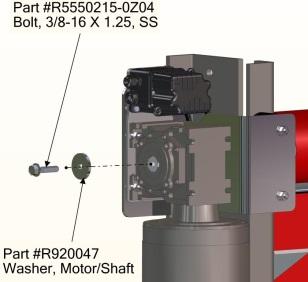
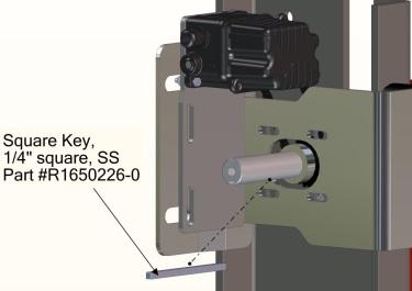
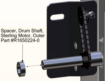
13 10. On the non-drive side the distance of the protruding shaft end should be approximately 1-9/16. On the drive side, the shaft end should protrude 6-1/16 as measured from the outer most part of the bearing to the shaft end. Loosely tighten the set screw in the bearing bracket to the shaft. It may need to be adjusted later. Align side column with the wall jamb. 11. Shim and adjust the side column to achieve plumb and square. Once the side column is plumb and square, bar clamp it to the wall. 12. Anchor the wall bracket. DO NOT tighten the anchors securely at this time - they will be fully tightened after door assembly is plumb and square. 13. Anchor the floor angle bracket. DO NOT tighten the anchors securely at this time - they will be fully tightened after door assembly is square and plumb. 14. When both columns are set, clamped down, and snugly anchored in place, check the overall plumb, square, and parallel of the side columns. Compare the diagonal measurements and the upper and lower horizontal measurements across the columns. The columns are square and parallel when the diagonal measurements are equal and the horizontal measurements are equal. If either column requires slight repositioning (when the difference of either comparison is greater than¹/₄ in.), use a block of wood and a mallet to nudge the column into position. 15. Check the position of the Drum/Panel assembly and adjust if necessary. 16. Install the motor spacer onto the drive side of the drum s drive shaft. 17. Install the key into the drive shaft keyway. The key must be flush with the end of the shaft. (See Figures 15 & 16) INSTALLATION SIDE COLUMNS AND HEAD ASSEMBLY NOTE: Never use a hammer or other hard metallic device to force a key into a keyway. Limit Switch Sprocket Chain, ¼ pitch #R for LH #R for RH Figure 16 Wall Anchor Installed in Wall Bracket 18. Install limit switch sprocket onto shaft. (See Figure 16) 19. Install additional motor spacer onto shaft. (See Figure 16) 20. Install limit switch drive chain onto the limit sprocket. Chain and master link are located in the small parts carton. Use #R (56 link chain-shorter) for Left Hand Motor Drive units and #R (64 link chain-longer) for Right Hand Motor Drive units (See Figure 16) 21. Align the slot of the motor/gearbox assembly with the key on the shaft. (See Figure 17) 22. Slide the assembly onto the shaft until it butts against the motor spacer. (See Figure 17) Motor Spacer 6.06 Drive Side Bearing Block Limit Switch Sprocket Additional Motor Spacer Figure 15 Motor Mount Key Figure 17 7
 NOTE: The locking collar on the opposite side might have to be loosened in order for the motor/gearbox and door panel")
, check that the head assembly is level and tighten all hardware and anchors. MOTOR ADJUSTMENT Figure 18 24. Tighten the serrated flange bolt to 20 ft-lbs torque. 25.")
 Attached to the motor is a bracket with 2 rubber bumpers. The bracket has 2 rubber bumpers that should fit tightly against the side column when installed properly.")
 can provide assistance to hold the bracket against the side column while tightening the four hex head bolts. (See Figure 21) Figure 19 26.")
14 INSTALLATION SIDE COLUMNS AND HEAD ASSEMBLY 23. Apply a mild thread lock (Loctite) to the serrated flange bolt prior to installation. Install washer and ³/₈-16 x 1.5 in. serrated flange bolt to secure the motor assembly (See Figure 18) NOTE: The locking collar on the opposite side might have to be loosened in order for the motor/gearbox and door panel assembly to be properly set into position. Figure Recheck the locking collar on the opposite side. Readjust as needed and tighten collar. 28. Using a carpenter s level (4-ft. minimum length), check that the head assembly is level and tighten all hardware and anchors. MOTOR ADJUSTMENT Figure Tighten the serrated flange bolt to 20 ft-lbs torque. 25. Install the limit switch chain around the two limit sprockets. The plate on the back of the motor can be adjusted up and down to allow for installation. (See Figure 19 & 20) Attached to the motor is a bracket with 2 rubber bumpers. The bracket has 2 rubber bumpers that should fit tightly against the side column when installed properly. The bracket can be adjusted towards or away from the door. Loosen the four hex head bolts and push the bracket towards the side column. A (C-Clamp) can provide assistance to hold the bracket against the side column while tightening the four hex head bolts. (See Figure 21) Figure The limit switch chain should be lubricated with LPS Brand Force 842 Dry Moly Lube (or equal) once installed and periodically as recommended to insure proper performance. Figure 21 8


15 INSTALLATION PHOTO EYES PHOTO EYES Your door is equipped with two photo eyes mounted on the front of the door. The purpose of these photo eyes is to hold the door open or, if the door is closing, reverse the door to the open position if a vehicle, person, or any object is in the path of the photo eye beam. The photo eye is not active when the door is closed. After the obstruction breaking the photo eye beam is removed: The door will remain open if it was originally opened by a non-automatic activator until it is closed by a non-automatic activator. The door will close automatically if it was originally opened with an automatic activator. NOTE: The photo eyes are not intended to be used as a door activator and will not open the door when it is closed. This system consists of one pair of non-adjustable emitter and receiver modules. There are no gain or sensitivity settings. Figure Adjust the lock nuts so that the photo eye protrudes ⅛ to ¼ inch from the end of the assembly. (See Figure 24) 1. Thread the first lock nut onto the shaft of the photo eye. 2. Connect the photo eye cable. 3. Insert photo eye into the side column. (See Figure 22) NOTE: Approximate height of photo eyes is 22 in. from floor. Figure Connect and route the short cable up the side column to the control board. 7. Connect and route the longer cable up the side column and across the head assembly to the control board. Figure Thread the last lock nut onto the front photo eye. (See Figure 23) 8. Make sure that the cables are not interfering with any moving parts. Apply plastic ties as required. 9

 NOTE: Back side of door is shown without the wall. Figure 26 3. With the door panel in the fully-open, position top seal assembly as needed. 4.")

16 INSTALLATION TOP SEAL TOP SEAL The top seal for the Rytec Wynd Star MT door. The disconnect must be in the OFF position and properly locked and tagged before performing the following procedure. 1. Install top hood bracket with two ³/₈-16 x 1.25 flat head square neck bolts, ³/₈-in. flat washers and ³/₈in. hex serrated flange lock nuts. (See Figure 25) NOTE: Back side of door is shown without the wall. Figure With the door panel in the fully-open, position top seal assembly as needed. 4. Mount track to wall. NOTE: Hardware is NOT provided choose hardware appropriate for your installation. (See Figure 27) Figure Install the top seal assembly to the top hood brackets using a ³/₈-16 x 1.50 hex head cap screw, five ³/₈-in. washers, and a ³/₈-in. lock nut at each end. Use three of the washers between the top hood bracket and lifting arm and one under each piece of hardware. (See Figure 26) Figure Restore power to the door and perform an operations check. 10


 Optional Rear Seal Figure 29 Top Hood Bracket 5.")
 Bottom Front Hood Bracket Figure 28 3.")
17 INSTALLATION HOOD HOOD The hood for the Rytec Wynd Star MT door. NOTE: If the top seal assembly is already installed, use the pre-existing brackets. If there is no top seal assembly, then the following brackets will have to be installed. 4. Install the rounded front corner trim on top panel. Use #8 x ⁵/₈-in pan head screws. (See Figure 29) NOTE: This piece should be mounted flush with the flat corner trim. Screws can be mounted on either side of the trim. For a cleaner look, screws can be mounted on the inside of the trim. The disconnect must be in the OFF position and properly locked and tagged before performing the following procedure. 1. Install top hood bracket with two ³/₈-16 x 1.25 flat head square neck bolts, flat washers and hex serrated flange lock nuts. 2. Install bottom hood bracket with a ³/₈-16 x 1 round head square neck machine screw, washer and hex serrated flange lock nut. (See Figure 28) Optional Rear Seal Figure 29 Top Hood Bracket 5. Install top panel on hood mounting brackets: a. Make sure both ends of the top panel are square and even. Clamp top panel to mounting brackets. b. Mark and lay out hole positions in the top panel. NOTE: Mark the hole locations by using the holes on the mounting brackets. c. Remove top panel and drill ³/₈-in. holes and deburr. (See Figure 30) Bottom Front Hood Bracket Figure Install the short and long rounded corner trims on motor cover side panel. Use #8 x ⁵/₈-in pan head screws. (See Figure 29) NOTE: Screws can be mounted on either side of the trim. For a cleaner look, screws can be mounted on the inside of the trim. Figure 30 11


18 INSTALLATION HOOD 6. Install two ³/₈-16 x 1.50 hex head cap bolts, washers, and nuts on both ends of the top panel. (See Figure 31) NOTE: Hardware is located in the small parts carton. Figure Install front panel of the hood assembly. Repeat procedure for locating, drilling, and deburring ³/₈in. holes. 8. Install ³/₈-16 x 1.50 hex head cap bolts, washers, and nuts on both ends of the front panel. (See Figure 32) Figure 32 12

 to manually open the door (See Figure 33).")

19 INSTALLATION MANUAL DOOR PANEL MOVEMENT MANUAL DOOR PANEL MOVEMENT The drive motor has 2 thumb screws at the bottom of the motor. The 2 thumb screws hold the brake cover onto the motor. Remove the 2 thumb screws and brake cover. Removing the brake cover will expose the motor shaft. A socket wrench or impact drive can be used to manually open the door. The door shipped with a 12 point, 15mm socket that can be placed onto the tool to turn the shaft. The manual brake release must be disengaged (1/4 turn clockwise) to manually open the door (See Figure 33). When the door is in the desired position, the manual brake release MUST be engaged (reset) to hold the position. Failure to engage the manual brake release will allow the door to move. Figure 34 Figure 33 Electrical power can be shut off anytime to operate the electric motor in manual mode. Control panel limit settings will not be affected when switching the power off and back on. The door will return to a normal operating mode. DOOR LIMITS Remove the cover to the black rotary limit switch box (2 screws).the S-1 PE Bypass limit switch is used to disable the photoeyes as the bottom edge of the door panel is approximately two inches above the photoeyes. Disabling the photoeyes will reduce false tripping condition caused by the door panel deflecting in a high wind condition. The photoeye bypass switch is located nearest the wall. The photoeye bypass limit cam has a 60 degree raised area to turn off the photoeyes when the edge is 2 inches above the photoeyes and remain off to the closed position(see Figure 34 & 35) Figure 35 Setting Limits The end of the rotary limit switch cams has 5 screws. The larger screw located in the middle is the central screw. This central screw locks the position of each of the white cams after adjustments are completed. The smaller screws are adjustment screws for each individual white cam. Next to each small screw is a number (1-4) indicating which limit cam will be adjusted when the screw is turned. The central screw (large) must be loosened to make adjustments to the individual cam screws (small). NOTE: Loosen central screw only ¼-½ turn to allow adjustment screws to turn freely. The central cam screw (large) must be tightened before moving the door or the white cam wheels will not turn properly and the adjustment will have to be repeated. (See Figure 36) Figure 36 13

.(see Figure 37) NOTE: The door panel must unroll from the back (wall side) of the barrel.")

 to lock the position. Figure 37 3.")
 to lock the position.")
20 INSTALLATION LIMIT SETTING The disconnect must be in the OFF position and properly locked and tagged before performing the following procedure. 1. Turn power off to the door. 2. Manually adjust the curtain panel until the bottom edge is centered on the outer reinsertion guides. Make note of the direction the white limit cams are turning, this will assist you in making the necessary adjustments required to the particular white cam requiring adjustment (clockwise or counterclockwise).(see Figure 37) NOTE: The door panel must unroll from the back (wall side) of the barrel. NOTE: The S-1 PE Bypass limit switch is used to disable the photo eyes as the bottom edge of the door panel is approximately two inches above the photo eyes. Disabling the photo eyes will reduce false tripping condition caused by the door panel deflecting in a high wind condition. 6. Lower the curtain panel until the bottom edge makes light contact with the floor. (See Figure 39) Figure Loosen the central screw (large). Turn the adjustment screw for the open limit cam #3 until you hear the #3 limit micro switch click, then tighten the central screw (large) to lock the position. Figure Loosen the central screw (large). Turn the adjustment screw for the open limit cam #2 until you hear the #2 limit micro switch click, then tighten the central screw (large) to lock the position. Limit Switch Designations S1 Photo Eye Bypass limit (PE Bypass) nearest to wall. S2 Not Used S3 Closed Limit S4 Open Limit, farthest from wall. 4. Lower the curtain panel until the bottom edge is 2 inches above the photo eye sensors. (See Figure 38). Figure Loosen the central screw (large) Turn the adjustment screw for the PE bypass limit cam #1 until you hear the #1 limit micro switch click, then tighten the central screw (large) to lock the position. 14 Figure 40

 built into them.")


21 INSTALLATION DOOR LIMITS Close Timer (Optional) 1. The timer function allows the door to close automatically after a predetermined time. (See Figure 41 & 42) Note: The close timer (T4) is optional. Part number is R To place an order contact the Rytec parts department at or fax parts at To eliminate the auto close timer, remove the jumper between terminals 42 and 43 in the control box. Control with T4 auto close timer ADJUSTMENT ADJUSTMENT PHOTO EYE PHOTO EYE Both the emitter and receiver photo eyes have a green LED (light-emitting diode) built into them. When power is applied to the photo eyes, the green LED light will illuminate indicating that they are working. The receiver also has a yellow LED. Once the photo eyes are in alignment, the yellow light will turn on. 1. Loosen the screws on the emitter socket bracket and adjust the photo eye so that it is square to the mounting bracket assembly or side column. Tighten the screw when this is achieved. 2. Loosen the screw on the receiver socket bracket and adjust the photo eye until the yellow LED illuminates. NOTE: The door will not operate until the photo eyes are in alignment. SERVICE ACCESS Prior to any adjustments, parts removal, or lubrication to the head assembly, the hood may need to be removed. Figure 41 Control without T4 auto close timer The disconnect must be in the OFF position and properly locked and tagged before performing the following procedure. 1. Remove the six hex head cap screws, washers, and lock nuts from the hood assembly. (See Figure 44) Figure To adjust the T4 auto close timer turn the dial on the side clockwise to increase time and counterclockwise to decrease the auto close timer. (See Figure 43) Figure Perform maintenance as needed. Figure Secure the hood by performing the steps in reverse. 15

 from the side column. (See Figure 45) Figure 46 Figure 45 3. Remove the old weather seal by sliding it out of the track. 4. Slide a new brush seal into the track. 5.")
22 REPLACEMENT PROCEDURES BRUSH SEAL(S) REPLACEMENT PROCEDURES BRUSH SEAL(S) The disconnect must be in the OFF position and properly locked and tagged before performing the following procedure. The drum roll panel is attached to the drum roll using a clamp bar and rivets. The separate, smaller door panels below are attached to each other with a wind rib and two roll pins, one at each end. (See Figure 46 and Figure 47.) The roll pins are located about 1 in. from the end of the panel. 1. Remove the two acorn nuts and round head square neck machine screws. 2. Remove the bottom bar guide(s) from the side column. (See Figure 45) Figure 46 Figure Remove the old weather seal by sliding it out of the track. 4. Slide a new brush seal into the track. 5. Install bottom bar guide, round head screws, and acorn nuts. DOOR PANEL(S) The disconnect must be in the OFF position and properly locked and tagged before performing the following procedure. Drum Roll Panel 1. Make sure the door is in the closed position and the power turned off. NOTE: With the door in the closed position, the clamp bar should be exposed. If not, release the motor brake and manually turn the drum until it can be seen. See Manual Door Panel Movement section on page Remove the top seal (if installed). 3. Pop out the door panel from the side column(s). This will make the repair easier. 4. Remove roll pins from the ends of the wind rib. NOTE: The roll pins are located about 1 in. from the end of the panel. 5. Slide the wind rib out from between the drum roll panel and door panel. (See Figure 47) 16


23 REPLACEMENT PROCEDURES DOOR PANEL(S) Figure Remove the protective strip covering the hardware and clamp bar. (See Figure 48) Figure Clean the surface of the drum roll and remove any burrs from the rivet holes. 9. Reinstall the drum roll panel by performing the steps in reverse order. NOTE: Make sure the drum roll panel is installed straight. 10. Reinstall the wind rib between the drum roll panel and door panel. 11. Install roll pins into the ends of the wind rib. 12. Restore power to the door. Figure Drill out the rivets from the clamp bar and remove the drum roll panel. (See Figure 49) NOTE: The door panel will reset itself after the power has been restored. 13. Perform operations check. Adjust door limits as needed. Door Panel 1. Make sure the door is in the closed position and power turned off. 2. Pop out the door panel from the side column(s). This will make the repair easier. 3. Remove roll pins from the end of the wind ribs on the worn door panel. NOTE: The roll pins are located about 1 in. from the end of the panel. 4. Slide either the top or bottom wind rib out of the worn door panel. (See Figure 50) 17

 NOTE: The view of the motor/gearbox is from the back side 9. Perform operations check. Adjust door limits as needed.")
.")
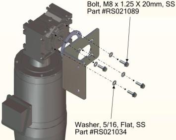
24 REPLACEMENT PROCEDURES MOTOR/GEARBOX NOTE: Label all connections as required. The wire diagram or schematic that came with the door should be used when reassembling the connections Figure Remove the worn door panel from the other wind rib. 6. Reinstall the new door panel by performing the steps in reverse order. 7. Install roll pins into the ends of the wind rib. 8. Restore power to the door. NOTE: The door panel will reset itself after the power has been restored Figure Loosen the four cap screws and slide the isolator bracket away from the side column. (See Figure 52) NOTE: The view of the motor/gearbox is from the back side 9. Perform operations check. Adjust door limits as needed. MOTOR/GEARBOX The disconnect must be in the OFF position and properly locked and tagged before performing the following procedure. 1. Make sure the door is in the open position. 2. Turn off the power. 3. Tie off the door panel assembly so that it will not unroll when the motor/gearbox is removed. 4. Gain access to the motor/gearbox by removing the hood (if installed). (See HOOD (OPTIONAL) on page 34) 5. Remove the top seal assembly. (See TOP SEAL (OPTIONAL) on page 32) Figure Remove serrated flange screw and flat washer from shaft end. (See Figure 53) 18
 NOTE: If you have any questions, contact your Rytec representative or call the Rytec Technical Support Department at 1-800-628-1909. 13.")
 Figure 56 Figure 54 10. Install the key in the slot of the shaft. 11.")
25 REPLACEMENT PROCEDURES MOTOR/GEARBOX Figure 55 Figure Remove motor/gearbox and bracket assembly from shaft. 9. Inspect key slot on the shaft end for wear and tear. Refurbish as needed. (See Figure 54) NOTE: If you have any questions, contact your Rytec representative or call the Rytec Technical Support Department at Align the keyway and install the motor/gearbox onto the shaft. NOTE: Put a coat of anti-seize on the shaft to ease the installation and removal of the motor. 14. Install serrated flange screw and flat washer onto shaft end. (See Figure 56) Figure 56 Figure Install the key in the slot of the shaft. 11. Remove the isolator bracket from the old motor/ gearbox. 12. Install the four cap screws, lock washers, and flat washers through the isolator bracket and into the new motor/gearbox. (See Figure 55) 15. The limit switch chain should be checked and lubricated any time it is serviced to insure appropriate coverage after handling. 16. Connect the door operator and electrical connections to the motor/gearbox. 17. Restore power to the door and perform an operations check. Adjust door limits as needed. 18. Install hood and end panel. 19. Return door to service. 19


26 PLANNED MAINTENANCE RECOMMENDED SCHEDULE PLANNED MAINTENANCE RECOMMENDED SCHEDULE NOTE: The following maintenance schedule is recommended for the Rytec Cycle-Plus maintenance program. Visual Damage Inspection Check Door Operation Photo Eye Inspection Hardware Inspection Wall Anchor Inspection Fabric Inspection Weather Seal Inspection Close-Limit Inspection Open-Limit Inspection Motor Brake Inspection Bottom Bar Inspection Activator and Control Panel Inspection Electrical Connection Inspection Lubrication DAILY INSPECTION Visual Damage Inspection Daily Quarterly Visually inspect the door to see that components have not been damaged. Example: bent bottom bar assembly, torn fabric panel, damage to side columns, etc. (See Figure 57) Head Assembly: Inspect for dents or damage that may prevent the door from opening or closing properly. Door Panel: Inspect panel for holes, tears, and worn areas. If equipped with windows, inspect them for damage or dirt that may impair vision clean or replace as required. Side Columns: Inspect for damage that may prevent the door from operating properly. Photo Eyes: Inspect the lens of each photo eye for damage or dirt that may prevent the photo eyes from working properly clean or replace as required. Bottom Bar: Inspect the bottom bar for damaged, missing, or loose hardware. Inspect the yellow vinyl seal along the lower edge of the bottom bar for tears and holes. Inspect the edge itself. Check Door Operation Run the door through four or five complete cycles to verify that the door is operating smoothly and efficiently, and that binding or unusual noises do not exist. DO NOT continue to operate the door if it is not running properly, as this could compound the damage. Photo Eye Inspection NOTE: Photo eyes act as a safety device to prevent the door from closing if an object or person is within either photo eye beam. The photo eyes are not meant to be used as door activators. Once power is applied, green lights on the photo eye emitter and receiver indicate that the modules are powered up. When the yellow light on the receiver module is also lit, the emitter and receiver are properly aligned. Placing your hand in front of the receiver breaks the light path and causes the yellow light to go out. Removing your hand causes the yellow light to come back on. (See Figure 58) Figure 57 Figure 58 20

 HEAD ASSEMBLY 2. Gain access to floor and wall anchors. 3. Inspect for loose or worn anchor(s). (See Figure 61) Figure 59 SIDE COLUMN ANCHORS Figure 61 4.")
27 PLANNED MAINTENANCE QUARTERLY INSPECTION QUARTERLY INSPECTION Anchor Inspection 1. Turn off power to the door. The disconnect must be in the OFF position and properly locked and tagged before performing the following procedure. Hardware Inspection Make sure all nuts, bolts, set screws, and anchors are tight throughout the door. Example: motor mounting bolts, wall mounting hardware, floor anchors, set screws, etc. (See Figure 59 & 60) HEAD ASSEMBLY The disconnect must be in the OFF position and properly locked and tagged before performing the following procedure. 2. Gain access to floor and wall anchors. 3. Inspect for loose or worn anchor(s). (See Figure 61) Figure 59 SIDE COLUMN ANCHORS Figure Tighten, repair, or replace anchor(s) as needed. NOTE: Remove door from service if any repairs are needed. All repairs must be done in accordance with municipal building codes. 5. Restore power to the door and return to service. Figure 60 21


28 PLANNED MAINTENANCE QUARTERLY INSPECTION Fabric Inspection 1. Turn off power to the door. The disconnect must be in the OFF position and properly locked and tagged before performing the following procedure. 2. Check the fabric for holes, tears and worn areas. Repair or replace as required. 3. If your door panel is equipped with windows inspect them for damage or dirt that may impair vision. Clean or replace as required. IMPORTANT: Use any good brand of window cleaner to clean the windows. DO NOT use abrasive cleaners or petroleum-based solvents. 4. Ensure the panel is securely fastened to the bottom bar assembly. Tighten or replace loose or damaged mounting hardware as required. (See Figure 62) Bottom Loop Inspection Figure Move the bottom bar of the door to a convenient height for inspection and turn off power. The disconnect must be in the OFF position and properly locked and tagged before performing the following procedure. 2. Inspect the sealed bladder inside the bottom vinyl loop of the door panel. Replace if the loop is damaged or leaking sand. (See Figure 64.) NOTE: Remove door from service until repairs have been performed. The sealed bladder is filled with sand and is an important integral part for smooth operation. Figure Make sure the wind ribs are in place and tightly secured. (See Figure 63) Figure 64 22

 Figure 67 Door Limit Inspection CLOSE LIMIT Figure 65 With the door in the closed position, check the black and yellow vinyl loop. It should be positioned as shown in figure 66.")
 Motor Brake Inspection The power drive brake assembly is designed to stop the door panel travel at the locations indicated in the limit switch inspection section.")
29 PLANNED MAINTENANCE QUARTERLY INSPECTION Brush Seal Inspection NOTE: The door seals are mounted on the inside lip of each side column. 1. Inspect all four door seals on the side columns for wear and tear. Replace as necessary. (See Figure 65) OPEN LIMIT The open limit position should be adjusted so that the door travel allows the bottom bar assembly to stop when it is centered on the outer reinsertion guides. (See Figure 67) Figure 67 Door Limit Inspection CLOSE LIMIT Figure 65 With the door in the closed position, check the black and yellow vinyl loop. It should be positioned as shown in figure 66. Damage to the vinyl loop or other parts can occur if the door seal is allowed to seal too tightly against the floor. (See Figure 66) Motor Brake Inspection The power drive brake assembly is designed to stop the door panel travel at the locations indicated in the limit switch inspection section. If the limit switches are set properly and the door drifts past the set limits, the brake may require adjustment. Bottom Bar Inspection 1. Inspect the hardware to secure the bottom loop assembly. Tighten or replace hardware as required. 2. Inspect the black and yellow vinyl seal for tears and abrasion. Replace any worn or damaged parts as required. (See Figure 68) Figure 68 Figure 66 23

30 PLANNED MAINTENANCE QUARTERLY INSPECTION Activator Inspection 1. Inspect all warning and safety labels. All labels should be intact, clean, and clearly legible, Replace any label when necessary. 2. Operate the door five or six complete open and closed cycles with each activator installed with the door, Make any necessary adjustments or repairs. Refer to the associated manual supplied with each activator installed with your door. Typical activators may include a floor loop. Pull cord, push button, motion detector, radio control, or photo eye. The door open cycle is controlled by the activator. The door close cycle can be controlled by an activator or by a timer internal to the control panel. Electrical Connection Inspection Lubrication The disconnect must be in the OFF position and properly locked and tagged before performing the following procedure. 1. Turn off power to the door. 2. Remove the side covers. 3. Bearing Blocks: The drum roll is supported by a bearing block located at each end of the drum roll. Each bearing block has a lubrication fitting. (See Figure 69) The bearings should be lubricated quarterly using a lithium based grease conforming to NLGI grade 2 standard. It should be a medium-viscosity, lowtorque rated grease, with an approved operating temperature range of 30 F to 200 F. The disconnect must be in the OFF position and properly locked and tagged before performing the following procedure. 1. Turn off power to the door. 2. Inspect all electrical connections to the power drive system. All connections must be secure, tight, and dry. 3. Inspect the electrical connections in the junction box located near the head assembly. All connections must be secure, tight, and dry. 4. For proper door operator electrical connection, see the wire diagram or schematic that came with the door. Figure Drive Motor Assembly: The motor assembly is a sealed unit and doesn't require any lubrication of oil or grease. 5. Limit Switch Chain: The limit switch chain should be lubricated with LPS Brand Force 842 Dry Moly Lube (or equal) once installed and as specified in the manual after that to insure proper performance. 6. Install the hood if removed. 7. Restore power to the door. 24
31 MISCELLANEOUS MISCELLANEOUS PANEL CLEANING With all adjustments to the door complete, clean both sides of each panel with a general household surface cleaner using a clean, soft cloth. PHOTO EYES Operation Your Rytec Wynd Star MT Door is equipped with a pair of photo eyes for monitoring the front side of the door, an emitter module, and a receiver module. The purpose of these photoeyes is to hold the door open or, if the door is closing, reverse the direction of the door if a person or object breaks the beam of light between the photoeyes. After the obstruction breaking the beam of light is removed: If the door was originally opened by an automatic activator, the door will close automatically. If the door was originally opened by a non-automatic activator, the door will remain open until it is closed by the non-automatic activator. NOTE: The photo eyes are not intended to be used as a door activator and will not open the door when it is closed. FINAL CHECKS NOTE: Check the following door systems and components after the door panel has been cycled at least 20 times. Head Assembly: Check that all mounting hardware is in place and tight. Side Columns: Check that the side columns are plumb and square and that all anchor bolts are tightly secured. Photo Eyes: Check that the photoeyes operate as described in PHOTOEYES on page 9 of this manual. Activators: Check to see that the activators operate as specified by the manufacturer. Open and Close Limits: Check open and close limits. See DOOR LIMITS starting on page 13 of this manual. Caulk: Ensure that all edges of the jamb and header frames and pullouts are sealed where they meet the wall of the building. Use a high-quality caulk rated for the environment in which the door is installed, as required. 25

32 PARTS LIST PARTS ORDERING INFORMATION PARTS LIST PARTS ORDERING INFORMATION How to Order Parts 1. Identify the parts required by referring to the following pages for part numbers and part descriptions. 2. To place an order, contact your local Rytec representative or the Rytec Technical Support Department at: or (fax). 3. To ensure the correct parts are shipped, please include the serial number of your door with the order. NOTE: Your DOOR SERIAL NUMBER information can be found on the control box/motor assembly, side columns, hood, and drum assy. (See Figure 70.) IMPORTANT: When installing multiple doors of the same model, verify the serial number in the control panel/motor assembly with the one in the side columns, hood, drum, and head assembly. Return of Parts Rytec will not accept the return of any parts unless they are labeled with a Return Merchandise Authorization (RMA) or Incident number. Before returning any parts, you must first contact the Rytec Technical Support Department and obtain an incident and Return Merchandise Authorization (RMA) number. Substitute Parts 26 Figure 70 Due to special engineering and product enhancement, the actual parts used on your door may be different from those shown in this manual. Also, if a part has been improved in design and bears a revised part number, the improved part will be substituted for the part ordered.
33 RYTEC TECHNICAL KNOWLEDGE CENTER RYTEC TECHNCIAL KNOWLEDGE CENTER At under the Customer Support tab a link to the Rytec Technical Knowledge Center can be found. This knowledge center contains on-line manuals, service bulletins and video presentations of various Rytec models and repair information. RYTEC ON-LINE WEBSTORE Instructions on how to return items: 1. Visit return center within your account to create a return merchandise authorization. 2. Print the returns slip and the shipping label. 3. Include the returns slip inside the box and affix the shipping label to the box. 4. Ship package. Prices subject to change. Rytec Corporation in partnership with Amazon have developed an on-line webstore for purchasing Rytec replacement parts. Access to the Rytec webstore is by invitation only. Invitations are processed through the following address, webstore@rytecdoors.com. Please include name and contact information (account holder). All inquiries will be reviewed however, Rytec maintains the authority to grant or deny access to the webstore at all times. The Rytec webstore is open 24/7/365. Parts available on-line require a credit card for purchase. Stocked items routinely ship the same day. The account is strictly for the account holder. All ship to, bill to, and ordering information is the responsibility of the account holder. Currently, over one hundred Rytec parts are available at the on-line store. Shipping rates for the products on line are the lowest rates available. RETURNS POLICY FOR ON-LINE WEBSTORE Customers may return new, unopened items within 30 days of delivery for a full refund. Items should be returned in their original packaging. The buyer will need to pay for the return shipments; return shipping costs will be refunded if the return is a result of merchant or Amazon error. All refunds go to the original purchaser. A full refund will be due provided the return is shipped back to RYTEC within the previously specified return period. Replacements and exchanges are not supported; customers can return their original order for a refund and create a new order for the replacement. Items classified as hazardous are not returnable. Please contact merchant for issues concerning these items. 27


34 PARTS LIST MOTOR ASSEMBLY MOTOR ASSEMBLY 28


35 PARTS LIST MOTOR ASSEMBLY Limit Chain, ¼ pitch #R for LH #R for RH 29


36 PARTS LIST MOTOR ASSEMBLY MOTOR ASSEMBLY 30


37 PARTS LIST SIDE COLUMN ASSEMBLY PARTS LIST SIDE COLUMN ASSEMBLY 31


38 PARTS LIST HEAD ASSEMBLY HEAD ASSEMBLY TOP SEAL 32


39 HEAD ASSEMBLY HOOD & DRUM Screw, #8 Phil Pan Tap #R Z04 Panel, Hood Ceiling #R HEAD ASSEMBLY HOOD PARTS Reference Assembly #R Corner, Trim ¾ x 3 #R Trim, Hood Cap #R Bolt, 3/8-16 x 1.00 Round Head Square Neck #RS Bracket, Front Btm Hood #R Washer, 3/8 Flat #RS Nut, 3/8-16 Hex Serrated Flanged #RS Screw, 3/8-16 x 1.50 Hex Head Cap #RS Nut, 3/8-16 Hex Serrated Flanged #RS ALWAYS INCLUDE SERIAL NUMBER OF DOOR WHEN PLACING ORDER To ensure you receive the correct parts when placing an order, always include the serial number of your door. Also, due to product enhancement, the actual parts on your door may be different from those shown in this manual. 33


40 PANEL ASSEMBLY PANEL ASSEMBLY ALWAYS INCLUDE SERIAL NUMBER OF DOOR WHEN PLACING ORDER To ensure you receive the correct parts when placing an order, always include the serial number of your door. Also, due to product enhancement, the actual parts on your door may be different from those shown in this manual. 34


41 PHOTO EYES PHOTO EYES ALWAYS INCLUDE SERIAL NUMBER OF DOOR WHEN PLACING ORDER To ensure you receive the correct parts when placing an order, always include the serial number of your door. Also, due to product enhancement, the actual parts on your door may be different from those shown in this manual. 35

42 ELECTRICAL SCHEMATIC ELECTRICAL SCHEMATIC LIMITS & MOTOR 36

43 ELECTRICAL SCHEMATIC - CONTROL PANEL ELECTRICAL SCHEMATIC EXTERNAL 3 & 4 WIRE CONTROLS NOTE: All external devices MUST be dry contacts, contain no voltage. Many automated carwash controllers send voltage signals under certain conditions during the carwash cycle. These signals will impact the operation of the door. If using automated controls, the controls MUST be a 4 wire dry contact system. Contact closure to open or close the door. The 3 wire automated system CANNOT be directly connected to the control box. The 3 wire system will require a relay be installed, to separate the signals. If you re unsure please contact Rytec Technical Support at , please provide the door serial number when calling Rytec. 37

44 ELECTRICAL SCHEMATIC ELECTRICAL SCHEMATIC - CONTROL BOX PARTS 38

45 ELECTRICAL SCHEAMTIC - PHOTOEYES ELECTRICAL SCHEMATIC EXTERNAL 3 & 4 WIRE CONTROLS NOTE: All external devices MUST be dry contacts, contain no voltage. Many automated carwash controllers send voltage signals under certain conditions during the carwash cycle. These signals will impact the operation of the door. If using automated controls, the controls MUST be a 4 wire dry contact system. Contact closure to open or close the door. The 3 wire automated system CANNOT be directly connected to the control box. The 3 wire system will require a relay be installed, to separate the signals. If you re unsure please contact Rytec Technical Support at , please provide the door serial number when calling Rytec. 39
Pharma-Slide. Owner s Manual. [Revision: June 14, 2010, SL150000, Rytec Corporation 2005]
![Pharma-Slide. Owner s Manual. [Revision: June 14, 2010, SL150000, Rytec Corporation 2005]](/thumbs/85/91337417.jpg "Pharma-Slide. Owner s Manual. [Revision: June 14, 2010, SL150000, Rytec Corporation 2005]") Pharma-Slide Owner s Manual [Revision: June 14, 2010, SL150000, Rytec Corporation 2005] WARRANTY The Pharma-Slide High-Speed Door purchased by you (Buyer) should not be installed or operated before you
Pharma-Slide Owner s Manual [Revision: June 14, 2010, SL150000, Rytec Corporation 2005] WARRANTY The Pharma-Slide High-Speed Door purchased by you (Buyer) should not be installed or operated before you
Spiral LH-HZ. Owner s Manual
 R Y T E C Spiral LH-HZ Owner s Manual Models L - (11 ½ Side Column) S - (12 Side Column) P.O. Box 403, One Cedar Parkway, Jackson, WI 53037 Phone 262-677-9046 Fax 262-677-2058 Rytec E-mail: helpdesk@rytecdoors.com,
Owner s Manual. [Revision: January 22, 2013, , Rytec Corporation 2004]
![Owner s Manual. [Revision: January 22, 2013, , Rytec Corporation 2004]](/thumbs/81/83430355.jpg "Owner s Manual. [Revision: January 22, 2013, , Rytec Corporation 2004]") Turbo-Seal Owner s Manual [Revision: January 22, 2013, 0815002, Rytec Corporation 2004] TURBO SEAL TS6000, TS6000R & TS6000SR SELF REPAIR LIMITED WARRANTY Rytec Corporation ( Seller ), an Illinois corporation
Turbo-Seal Owner s Manual [Revision: January 22, 2013, 0815002, Rytec Corporation 2004] TURBO SEAL TS6000, TS6000R & TS6000SR SELF REPAIR LIMITED WARRANTY Rytec Corporation ( Seller ), an Illinois corporation
(Motorized Operation)
") Bantam (Motorized Operation) Installation & Owner s Manual [Revision: September 23, 2004, 0-815-009, Rytec Corporation 2004] WARRANTY The Bantam Dock Door purchased by you (Buyer) should not be installed
Bantam (Motorized Operation) Installation & Owner s Manual [Revision: September 23, 2004, 0-815-009, Rytec Corporation 2004] WARRANTY The Bantam Dock Door purchased by you (Buyer) should not be installed
Spiral. Owner s Manual. Models. L & L/R (9 1 /2" Side Column) S & S/R (14" Side Column) [Revision: October 2, 2008, , Rytec Corporation 2005]
![Spiral. Owner s Manual. Models. L & L/R (9 1 /2 Side Column) S & S/R (14 Side Column) [Revision: October 2, 2008, , Rytec Corporation 2005]](/thumbs/79/78936713.jpg "Spiral. Owner s Manual. Models. L & L/R (9 1 /2 Side Column) S & S/R (14 Side Column) [Revision: October 2, 2008, , Rytec Corporation 2005]") Spiral Owner s Manual Models L & L/R (9 1 /2" Side Column) S & S/R (14" Side Column) [Revision: October 2, 2008, 0915005, Rytec Corporation 2005] WARRANTY The Spiral High-Speed Door purchased by you (Buyer)
Spiral Owner s Manual Models L & L/R (9 1 /2" Side Column) S & S/R (14" Side Column) [Revision: October 2, 2008, 0915005, Rytec Corporation 2005] WARRANTY The Spiral High-Speed Door purchased by you (Buyer)
Spiral HZ. Owner s Manual
 R Y T E C Spiral HZ Owner s Manual P.O. Box 403, One Cedar Parkway, Jackson, WI 53037 Phone 262-677-9046 Fax 262-677-2058 Rytec E-mail: helpdesk@rytecdoors.com, Parts E-mail: parts@rytecdoors.com [Revision:
R Y T E C. Powerhouse. Model SD. Owner s Manual
 R Y T E C Powerhouse Model SD Owner s Manual P.O. Box 403, One Cedar Parkway, Jackson, WI 53037 Phone: 262-677-9046 Fax: 262-677-2058 Rytec Website: www.rytecdoors.com, Rytec On-line store: www.rytecparts.com
R Y T E C. Pharma Seal
 R Y T E C Pharma Seal Installation Manual P.O. Box 403, One Cedar Parkway, Jackson, WI 53037 Phone: 262-677-9046 Fax: 262-677-2058 Rytec website: www.rytecdoors.com Rytec On-line store: www.rytecparts.com
PredaDoor. Owner s Manual. [Revision: August 15, 2008, , Rytec Corporation 2004]
![PredaDoor. Owner s Manual. [Revision: August 15, 2008, , Rytec Corporation 2004]](/thumbs/84/89660787.jpg "PredaDoor. Owner s Manual. [Revision: August 15, 2008, , Rytec Corporation 2004]") PredaDoor Owner s Manual [Revision: August 15, 2008, 0715002, Rytec Corporation 2004] WARRANTY The PredaDoor High-Speed Door purchased by you (Buyer) should not be installed or operated before you read
PredaDoor Owner s Manual [Revision: August 15, 2008, 0715002, Rytec Corporation 2004] WARRANTY The PredaDoor High-Speed Door purchased by you (Buyer) should not be installed or operated before you read
R Y T E C. Fast-Seal
 R Y T E C Fast-Seal Installation Manual P.O. Box 403, One Cedar Parkway, Jackson, WI 53037 Phone: 262-677-9046 Fax: 262-677-2058 Rytec website: www.rytecdoors.com Rytec On-line store: www.rytecparts.com
Turbo-Seal Self Repair
 Turbo-Seal Self Repair Owner s Manual [Revision: August 15, 2008, SR150001, Rytec Corporation 2007] WARRANTY The Turbo-Seal Self Repair High-Speed Door purchased by you (Buyer) should not be installed
R Y T E C. Turbo Seal Insulated Gen 2
 R Y T E C Turbo Seal Insulated Gen 2 Owner s Manual P.O. Box 403, One Cedar Parkway, Jackson, WI 53037 Phone: 262-677-9046 Fax: 262-677-2058 Rytec Website: www.rytecdoors.com, Rytec On-line store: www.rytecparts.com
Self Repair. Installation Manual. [Revision: August 14, 2008, SR150000, Rytec Corporation 2007]
![Self Repair. Installation Manual. [Revision: August 14, 2008, SR150000, Rytec Corporation 2007]](/thumbs/82/85314666.jpg "Self Repair. Installation Manual. [Revision: August 14, 2008, SR150000, Rytec Corporation 2007]") Turbo-Seal Self Repair Installation Manual [Revision: August 14, 2008, SR150000, Rytec Corporation 2007] TABLE OF CONTENTS PAGE INTRODUCTION.............................................1 DOOR SERIAL NUMBER(S)...........................................1
Turbo-Seal Self Repair Installation Manual [Revision: August 14, 2008, SR150000, Rytec Corporation 2007] TABLE OF CONTENTS PAGE INTRODUCTION.............................................1 DOOR SERIAL NUMBER(S)...........................................1
R Y T E C. Spiral VP Spring Balanced (SVP-B)
") R Y T E C Spiral VP Spring Balanced (SVP-B) Installation Manual P.O. Box 403, One Cedar Parkway, Jackson, WI 53037 Phone 262-677-9046 Fax 262-677-2058 Rytec website: www.rytecdoors.com Rytec On-line store:
R Y T E C Spiral VP Spring Balanced (SVP-B) Installation Manual P.O. Box 403, One Cedar Parkway, Jackson, WI 53037 Phone 262-677-9046 Fax 262-677-2058 Rytec website: www.rytecdoors.com Rytec On-line store:
R Y T E C. Pharma Seal
 R Y T E C Pharma Seal Owner s Manual P.O. Box 403, One Cedar Parkway, Jackson, WI 53037 Phone: 262-677-9046 Fax: 262-677-2058 Rytec website: www.rytecdoors.com Rytec On-line store: www.rytecparts.com Rytec
R Y T E C. Installation Manual. Models. L (9-½ Side Column) S (14 Side Column)
 S (14 Side Column)") R Y T E C Spiral LH Installation Manual Models L (9-½ Side Column) S (14 Side Column) P.O. Box 403, One Cedar Parkway, Jackson, WI 53037 Phone 262-677-9046 Fax 262-677-2058 Rytec website: www.rytecdoors.com
R Y T E C Spiral LH Installation Manual Models L (9-½ Side Column) S (14 Side Column) P.O. Box 403, One Cedar Parkway, Jackson, WI 53037 Phone 262-677-9046 Fax 262-677-2058 Rytec website: www.rytecdoors.com
R Y T E C. Turbo-Seal Insulated Gen 2
 R Y T E C Turbo-Seal Insulated Gen 2 Installation Manual P.O. Box 403, One Cedar Parkway, Jackson, WI 53037 Phone: 262-677-9046 Fax: 262-677-2058 Rytec Website: www.rytecdoors.com, Rytec On-line store:
Fast-Fold. Pneumatic Door. Owner s Manual. [Revision: February 23, , Rytec Corporation 2004]
![Fast-Fold. Pneumatic Door. Owner s Manual. [Revision: February 23, , Rytec Corporation 2004]](/thumbs/95/123644895.jpg "Fast-Fold. Pneumatic Door. Owner s Manual. [Revision: February 23, , Rytec Corporation 2004]") Fast-Fold Pneumatic Door Owner s Manual [Revision: February 23, 2006 0-415-238, Rytec Corporation 2004] WARRANTY The Fast-Fold High-Speed Door purchased by you (Buyer) should not be installed or operated
Fast-Fold Pneumatic Door Owner s Manual [Revision: February 23, 2006 0-415-238, Rytec Corporation 2004] WARRANTY The Fast-Fold High-Speed Door purchased by you (Buyer) should not be installed or operated
SURVIVOR 450S Impactable Dock Shelter (V-Flow Option)
") SURVIVOR 450S Impactable Dock Shelter (V-Flow Option) This Installation/Owner s manual covers units shipped: 4/2010 to Date Installed on: See supplemental instructions for other header options. Notice
SURVIVOR 450S Impactable Dock Shelter (V-Flow Option) This Installation/Owner s manual covers units shipped: 4/2010 to Date Installed on: See supplemental instructions for other header options. Notice
Spiral. Installation Manual. [Revision: December 22, 2005, , Rytec Corporation 2001]
![Spiral. Installation Manual. [Revision: December 22, 2005, , Rytec Corporation 2001]](/thumbs/79/78936654.jpg "Spiral. Installation Manual. [Revision: December 22, 2005, , Rytec Corporation 2001]") Spiral Installation Manual [Revision: December 22, 2005, 0-915-004, Rytec Corporation 2001] TABLE OF CONTENTS PAGE INTRODUCTION.............................................1 HOW TO USE MANUAL..............................................1
Spiral Installation Manual [Revision: December 22, 2005, 0-915-004, Rytec Corporation 2001] TABLE OF CONTENTS PAGE INTRODUCTION.............................................1 HOW TO USE MANUAL..............................................1
Fast-Fold. Owner s Manual. [Revision: May 14, 2008, , Rytec Corporation 2002]
![Fast-Fold. Owner s Manual. [Revision: May 14, 2008, , Rytec Corporation 2002]](/thumbs/95/125504599.jpg "Fast-Fold. Owner s Manual. [Revision: May 14, 2008, , Rytec Corporation 2002]") Fast-Fold Owner s Manual [Revision: May 14, 2008, 0-115-564, Rytec Corporation 2002] WARRANTY The Fast-Fold High-Speed Door purchased by you (Buyer) should not be installed or operated before you read
Fast-Fold Owner s Manual [Revision: May 14, 2008, 0-115-564, Rytec Corporation 2002] WARRANTY The Fast-Fold High-Speed Door purchased by you (Buyer) should not be installed or operated before you read
PN: 6410T0022 Rev. 8/18/2014 Revision D Albany RR300 Stainless Mechanical Install & Owner s Manual
 PN: 6410T0022 Rev. 8/18/2014 Revision D Albany RR300 Stainless Mechanical Install & Owner s Manual ASSA ABLOY ENTRANCE SYSTEM. All Rights Reserved 975-A Old Norcross Road, Lawrenceville, Georgia 30046
MODEL A OLD NORCROSS ROAD LAWRENCEVILLE, GA (770) TEL (770) FAX (877) TOLL FREE
 TEL (770) FAX (877) TOLL FREE") USER MANUAL RAPID-ROLL DOOR OWNER S MANUAL MODEL 230 975-A OLD NORCROSS ROAD LAWRENCEVILLE, GA 30045 (770) 338-5000 TEL (770) 338-5034 FAX (877) 925-2468 TOLL FREE Part # 6410T0009 Architectural Drawing
USER MANUAL RAPID-ROLL DOOR OWNER S MANUAL MODEL 230 975-A OLD NORCROSS ROAD LAWRENCEVILLE, GA 30045 (770) 338-5000 TEL (770) 338-5034 FAX (877) 925-2468 TOLL FREE Part # 6410T0009 Architectural Drawing
Spiral LH. Installation Manual. Models. L (11 ½ Side Column) S (12 Side Column)
 S (12 Side Column)") R Y T E C Spiral LH Installation Manual Models L (11 ½ Side Column) S (12 Side Column) P.O. Box 403, One Cedar Parkway, Jackson, WI 53037 Phone 262-677-9046 Fax 262-677-2058 Rytec E-mail: Helpdesk@rytecdoors.com,
R Y T E C Spiral LH Installation Manual Models L (11 ½ Side Column) S (12 Side Column) P.O. Box 403, One Cedar Parkway, Jackson, WI 53037 Phone 262-677-9046 Fax 262-677-2058 Rytec E-mail: Helpdesk@rytecdoors.com,
Installation Instructions
 85-4592 rev. 08 02-18 Installation Instructions Thank you for purchasing our sway bar kit. Please read through these instructions before installation. Auxiliary Rear Anti-Sway Bar Kit for Ford F53 part
UltraSlim Mechanical Install & Owner s Manual
 PN: 6410T0020 Version C Rev: 5/01/2012 UltraSlim Mechanical Install & Owner s Manual Doors are Ultra-Tough, Ultra-Reliable, and Ultra-Affordable. ASSA ABLOY ENTRANCE SYSTEMS All Rights Reserved 975-A Old
TS-2000 Trailer Stand
 TS-2000 Trailer Stand Installation/Owner's Manual This manual covers units: May 7, 2015 to Date NOTICE TO USER...................2 SAFETY...........................2 Safety Identifications.................2
Installation Instructions Table of Contents
 Installation Instructions Table of Contents Pre- Installation of Garage Storage Lift 2 Layout the Garage Storage Lift 3 Installing the strut Channels 3 Install the Drive Assembly 5 Install the Drive Shaft
Roller Door Operator
 INSTALLATION INSTRUCTIONS AND OWNERS MANUAL Roller Door Operator IMPORTANT PLEASE READ THESE INSTRUCTIONS CAREFULLY PRIOR TO COMMENCING THE INSTALLATION OF THE OPERATOR UNIT CAUTION This Automatic Opener
Users Guide for Ac-sync
 Problem solved. Users Guide for Ac-sync Thank you for choosing Anywhere Cart! The AC-SYNC is designed to sync, charge and store 1-36 ipads or tablets. Adjustable device divider bays allow fitment of any
CRD610 Automatic Fitting Inserter
 CRD610 Automatic Fitting Inserter OPERATIONS MANUAL VERSION 1.2 LAST EDITED 12.12.2018 cleanroomdevices.com 1 Table of Contents Title Page. 1 Table of Contents...2 1.0 General Product & Safety Information....3
CRD600 Automatic Fitting Inserter
 CRD600 Automatic Fitting Inserter OPERATIONS MANUAL VERSION 2.3 LAST EDITED 12.07.2018 cleanroomdevices.com 1 Table of Contents Title Page.. 1 Table of Contents. 2 1.0 General Product & Safety Information...3
RollSeal 1733 County Road 68 Bremen, Alabama Part No Rev Owner s Manual RS-Divider Curtain
 1. 2. 7 3. 4. RollSeal 1733 County Road 68 Bremen, Alabama 35033 256-287-7000 Part No 4801-5176 Rev 12-11-17 Owner s Manual RS-Divider Curtain Table of Contents 1 Warnings (Avertissements)... 3 2 Limited
Read this entire manual before operation begins.
 Read this entire manual before operation begins. Record below the following information which is located on the serial number data plate. Serial No. Model No. Date of Installation Contents Specifications.............
Installation Instructions
 85-3180 rev. 07 03-14 Installation Instructions Thank you for purchasing this antisway bar kit. Please read through these instructions before installation. Front Anti-Sway Bar Kit for the Ford E350/450
MOTORIZED FOLDING CAMPER WINCH
 OWNER'S MANUAL MOTORIZED FOLDING CAMPER WINCH With 1200lb Lift Capacity The 12 Volt Motorized Folding Camper Winch is used to raise and lower folding campers with the touch of the switch, eliminating hand
37SCENE 46SCENE 79SCENE
 Installation and Operation Instructions LED SCENE LIGHT LED SCENE LIGHT 37SCENE 46SCENE 79SCENE 37SCENE 46SCENE Introduction The 37SCENE, 46SCENE, 79SCENE LED Scene Lights are designed for the emergency
48" and 52" Hyflo Fans Installation and Operators Instruction Manual
 48" and 52" Hyflo Fans Installation and Operators Instruction Manual Thank You The employees of Chore-Time Equipment would like to thank your for your recent Chore-Time purchase. If a problem should arise,
LUBRICATOR GUN INSTRUCTIONS-PARTS LIST. 10,000 psi (700 bar) Maximum Delivery Pressure. Detachable-type
 Maximum Delivery Pressure. Detachable-type") INSTRUCTIONS-PARTS LIST 306 460 INSTRUCTIONS This manual contains important warnings and information. READ AND KEEP FOR REFERENCE. Rev. E Supercedes D Detachable-type LUBRICATOR GUN 10,000 psi (700 bar)
INSTRUCTIONS-PARTS LIST 306 460 INSTRUCTIONS This manual contains important warnings and information. READ AND KEEP FOR REFERENCE. Rev. E Supercedes D Detachable-type LUBRICATOR GUN 10,000 psi (700 bar)
CLEAN ROOM DEVICES, LLC "WHERE TUBING AND FITTINGS COME TOGETHER"
 CLEAN ROOM DEVICES, LLC "WHERE TUBING AND FITTINGS COME TOGETHER" CRD600 Automatic Fitting Inserter OPERATIONS MANUAL VERSION 2.1 LAST EDITED 7.25.14 DOCUMENT NUMBER 001 cleanroomdevices.com 1 Table of
Installation Instructions
 85-3195 rev. 12 04-18 Installation Instructions Thank you for purchasing this antisway bar kit. Please read through these instructions before installation. Part #1139-117 Rear Anti-Sway Bar Kit 1½ diameter
Spiral LH - HZ. Installation Manual
 R Y T E C Spiral LH - HZ Installation Manual P.O. Box 403, One Cedar Parkway, Jackson, WI 53037 Phone 262-677-9046 Fax 262-677-2058 Rytec E-mail: Helpdesk@rytecdoors.com, Parts E-mail: parts@rytecdoors.com
Linear Actuator. Installation Manual. warranty installation parts list. Linear Actuator Installation Manual Page 1
 Linear Actuator Installation Manual warranty installation parts list January 2004 Linear Actuator Installation Manual Page 1 MA1221B12 Warranty Information Chore-Time Equipment ( Chore-Time ) warrants
Installation Instructions
 85-3847 rev. 01 09-09 Installation Instructions Thank you for purchasing this anti-sway bar kit. Please read through these instructions before installation. Front Anti-Sway Bar TruTrac Bar Combo Kit for
GC-1. Roof and Gutter De-Icing Control Installation and Operating Instructions FOR EXTERIOR INSTALLATION ONLY
 GC-1 Roof and Gutter De-Icing Control Installation and Operating Instructions FOR EXTERIOR INSTALLATION ONLY GENERAL INFORMATION The GC-1 heating cable controller has been designed and manufactured for
Installation Instructions
 85-4341 rev. 04 10-15 Installation Instructions Thank you for purchasing this antisway bar kit. Please read through these instructions before installation. Rear Anti-Sway Bar Kit for Chevy 2500/3500/4500
04 & 14 F FRONT 1.0 REAR LEVELING KIT INSTALLATION
 INSTRUCTION PART NO 15312 KIT NO 3836 04 & 14 F-150 2.0 FRONT 1.0 REAR LEVELING KIT INSTALLATION READ INSTRUCTIONS COMPLETELY THROUGH BEFORE STARTING. FAILURE TO ADHERE TO THE INSTRUCTIONS WILL VOID ANY
Installation Instructions
 85-3511 rev. 04 11-15 Installation Instructions Polyurethane Bushing Kit for Ford F-53 (Front) (replaces OE bushings and brackets) part #4139-127 1-5/8 diameter INTRODUCTION Thank you for purchasing this
Installation Instructions
 Equipment Required: Fastener Kit: F Wrenches: 15/16, 10 mm Drill Bits: 1/4 Other Tools: Drill, Reciprocating Saw 9464/9474 HIDE-A-GOOSE HITCH INSTALLATION All Fasteners Typical, Both Sides WARNING: Under
Level Alert Model Multi-Switch Liquid Level Sensor. Assembly and Installation Instructions
 Level Alert Model 2000 Multi-Switch Liquid Level Sensor Assembly and Installation Instructions Kit Form Each unit is provided in kit form with step-by-step instructions, making it extremely easy to custom
Installation Instructions
 85-3909 rev. 01 09-09 Installation Instructions Thank you for purchasing this anti-sway bar kit. Please read through these instructions before installation. Rear Anti-Sway Bar Kit for Chevrolet G30 part
A S S E M B L Y I N S T R U C T I O N S
 A S S E M B L Y I N S T R U C T I O N S Please Do Not Return This Product to the Store! Contact Escalade Sports customer service department at: Phone: 1-888-USA-GOAL Toll-Free! Fax: 1-866-873-3536 Toll-Free!
Guardian Taper Grid Shaft Coupling
 Guardian Taper Grid Shaft Coupling P-8608-GC GUA-MRK-DOC-025 Service & Installation Instructions TABLE OF CONTENTS NOTICES AND WARNINGS PAGE 2 SECTION 1 COUPLING OVERVIEW PAGE 3 SECTION 2 TOOLS/MATERIALS
Installation Instructions
 85-3214 rev. 07 03-11 Installation Instructions Thank you for purchasing this anti-sway bar kit. Please read through these instructions before installation. Rear Anti-Sway Bar Kit Freightliner FL Series
DeZURIK 2 20" BOS BUTTERFLY VALVES
 2 20" BOS BUTTERFLY VALVES Instruction D10459 October 2013 2-20 BOS Butterfly Valves Instructions These instructions provide information about BOS Butterfly Valves. They are for use by personnel who are
Installation Instructions
 85-3700 rev. 08 05-18 Installation Instructions Thank you for purchasing this antisway bar kit. Please read through these instructions before installation. Front Anti-Sway Bar Kit for the F53 Chassis part
II DISTRIBUTION & SUBSTATION TYPE C
 CapCheckIII DISTRIBUTION & SUBSTATION TYPE Ca p a c i t o r C h e c ke r Operating & Instruction Manual 1475 Lakeside Drive Waukegan, Illinois 60085 U.S.A. 847.473.4980 f a x 8 4 7. 4 7 3. 4 9 8 1 w e
INSTALLATION INSTRUCTIONS SECURITY SHUTTER MODEL 523
 INSTALLATION INSTRUCTIONS SECURITY SHUTTER MODEL 523 READ THESE INSTRUCTIONS THOROUGHLY BEFORE ATTEMPTING TO INSTALL THIS DOOR! TABLE OF CONTENTS Warnings & Safety Information... 2 WHEN INSTALLATION Key
APCO CRF-100A RUBBER FLAPPER SWING CHECK VALVES
 APCO CRF-100A RUBBER FLAPPER SWING CHECK VALVES Instruction D12043 June 2016 DeZURIK Instructions These instructions provide installation, operation and maintenance information for APCO CRF-100A Rubber
CLEAN ROOM DEVICES, LLC "WHERE TUBING AND FITTINGS COME TOGETHER"
 CLEAN ROOM DEVICES, LLC "WHERE TUBING AND FITTINGS COME TOGETHER" CRD600AF Automatic Fitting Inserter With Auto Feed OPERATIONS MANUAL (Shown with optional alcohol dispenser) 1 VERSION 1.1 LAST EDITED
Part Number Mini Linear Lift Assembly Installation & Operator s Instruction Manual
 Part Number 39644 Mini Linear Lift Assembly Installation & Operator s Instruction Manual April 1999 MV1505C Chore-Time Warranty Mini Linear Lift Assembly Manual Chore-Time Warranty Chore-Time Equipment
ROUSH Short Throw Shifter Kit
 ROUSH Short Throw Shifter Kit Part Number 1310R7400 Application: 2010 Ford Mustang GT Installation Instructions Before installing your ROUSH Performance Product(s), read through the entire installation
Product/ Title Guardian Super Flex Shaft Coupling Product/ Title
 Product/ Title Guardian Super Flex Shaft Coupling Product/ Title GUA-MRK-DOC-027 P-XXXX-GC Service&&Installation Installation Instructions Instructions Service An Altra Industrial Motion Company TABLE
Please visit for the latest version of these installation instructions.
 Please visit www.blueox.com for the latest version of these installation instructions. BX1139 2018 Jeep Wrangler / Wrangler Unlimited (JL) (All Models w/standard Bumper) Attachment Tab Height: 18 Serial
RF6 / RF10 / RF18 Installation Instructions
 RF6 / RF10 / RF18 Installation Instructions Thank you very much for purchasing PIAA product. Read this instruction manual thoroughly for proper use of the product. After completing your installation, please
Installation and Operation Instructions Safety Director Arrow
 Installation and Operation Instructions Safety Director Arrow! WARNING! Failure to install or use this product according to manufacturers recommendations may result in property damage, serious bodily/personal
Read all instructions before installing and using. Installer: This manual must be delivered to the end user.
 Installation Instructions Vacuum / Magnet Mount Kits IMPORTANT! Read all instructions before installing and using. Installer: This manual must be delivered to the end user.! WARNING! Failure to install
Installation Instructions
 85-3207 rev. 03 05-06 Installation Instructions Thank you for purchasing this anti-sway bar kit. Please read through these instructions before installation. Rear Anti-Sway Bar Kit for the Freightliner
Please visit for the latest version of these installation instructions.
 Please visit www.blueox.com for the latest version of these installation instructions. BX2409 2009-18 Dodge Ram 1500 Sport/ST/Laramie Limited Please read BOTH these and the General Information sheet prior
Read this entire manual before operation begins.
 Read this entire manual before operation begins. Record below the following information which is located on the serial number data plate. Serial No. Model No. Date of Installation Contents Specifications.............
Model E600 Tarping System
 10 Boulder Parkway N. Oxford, MA 01537 866-353-5826 pioneersales@wastequip.com www.pioneercoverall.com Model E600 Tarping System Installation Instructions WARNING: In order to prevent damage, the tarp
Installation Instructions
 85-5029 rev. 03 06-17 Installation Instructions Thank you for purchasing our anti-sway bar kit. Please read through these instructions before installation. Rear Anti-Sway Bar Kit for Workhorse W22, Holiday
Installation Instructions
 85-3910 rev. 03 01-18 Installation Instructions Thank you for purchasing the antisway bar kit. Please read through these instructions before installation. Rear Anti-Sway Bar Kit for Ford F-250/F-350 part
900 SERIES SPLIT CASE FIRE PUMP REPAIR PARTS INDEX
 900 SERIES SPLIT CASE FIRE PUMP REPAIR PARTS INDEX Read and understand the pump and motor instructions before attempting to install, disassemble or repair the pump. Part # AF-03-326 2015 Pentair Ltd. 01/30/15
7.3L POWERSTROKE BANJO BOLT KIT Fits L Powerstroke Diesel. Installation Guide
 7.3L POWERSTROKE BANJO BOLT KIT Fits 94-03 7.3L Powerstroke Diesel Installation Guide INSPECT CONTENTS OF THIS KIT THOROUGHLY BEFORE STARTING THE INSTALLATION PROCESS! IF YOU FIND A PROBLEM WITH YOUR PACKAGE:
Installation Instructions
 Equipment Required: Fastener Kit: F Wrenches: 3/4, 15/16, 10mm, 18mm Drill Bits: 1/4 Other Tools: Drill, Reciprocating saw 9465/9475 HIDE-A-GOOSE HITCH INSTALLATION All Fasteners Typical, Both Sides WARNING:
Installation Instructions
 85-4209 rev. 05 11-18 Installation Instructions Thank you for purchasing this anti-sway bar kit. Please read through these instructions before installation. Factory Replacement Anti-Sway Bar Kit part #1129-135
Guardian Steel Gear Shaft Coupling
 Guardian Steel Gear Shaft Coupling P-8609-GC GUA-MRK-DOC-026 Service & Installation Instructions TABLE OF CONTENTS NOTICES AND WARNINGS PAGE 2 SECTION 1 COUPLING OVERVIEW PAGE 3 SECTION 2 TOOLS/MATERIALS
Installation Instructions
 85-3209 rev. 07 03-11 Installation Instructions Thank you for purchasing this anti-sway bar kit. Please read through these instructions before installation. Front Anti-Sway Bar Kit for Workhorse W22, Holiday
HBC-20 - LED HIGH BAY
 To prevent death, injury or damage to property, this product must be installed in accordance to National Electrical Code (NFPA70) in the US or Canadian Electrical Code (CSA.) in Canada. Risk of fire or
Model FM2642 Wall Mount. Full Motion Television Wall Mount
 Model FM2642 Wall Mount Full Motion Television Wall Mount Getting Started Introduction Congratulations on the purchase of your new Audio Solutions FM2642 Television Wall Mount. For maximum benefit, please
Installation Instructions
 Equipment Required: Fastener Kit: F Wrenches: 3/4, 15/16 Drill Bits: 1/4 Other Tools: Drill Short & Long Bed All Megacabs 9464/9474 HIDE-A-GOOSE HITCH INSTALLATION WARNING: Under no circumstances do we
Instruction Sheet SRSR SERIES. Rotating Sliding Rail System
 Instruction Sheet SRSR SERIES Rotating Sliding Rail System THANK YOU Thank you for purchasing the SRSR Series Rotating Sliding Rail System. Please read these instructions thoroughly before assembling this
Installation Instructions
 Equipment Required: Installation Instructions Fastener Kit: F Wrenches: 8mm, 13mm, 3/4, 15/16 Drill Bits: 1/4 Other Tools: Drill, Reciprocating Saw, File WARNING: Under no circumstances do we recommend
HATCHGRIP Installation Instructions/Operation and Maintenance Manual
 HATCHGRIP Installation Instructions/Operation and Maintenance Manual Models: HTG-PCG Contact Information Table of Contents: Safety Precautions... 2 Product Information... 2 Operation... 3 Installation
Please visit for the latest version of these installation instructions.
 Please visit www.blueox.com for the latest version of these installation instructions. Attachment Tab Height: 19-1/2 Serial Number Attachment Tab Width: 19 Please read BOTH these and the General Information
DeZURIK KUL KNIFE GATE VALVES
 KUL KNIFE GATE VALVES Instruction D11025 September 2013 Instructions These instructions are intended for personnel who are responsible for the installation, operation and maintenance of your KUL knife
Please visit for the latest version of these installation instructions.
 Please visit www.blueox.com for the latest version of these installation instructions. BX1986 Please read BOTH these and the General Information sheet prior to installing or operating this equipment. 1.
14", 18" & 24" Fiberglass Turbo Fans Installation & Operator s Instruction Manual
 14", 18" & 24" Fiberglass Turbo Fans Installation & Operator s Instruction Manual 09484:09#52
StormPro BA Series Sump Pump
 Page 1 of 8 Marks & Meanings DANGER: Keep the pump equipment out of the reach of children! Warns that the failure to follow the directions given could cause serious risk to individuals or objects. WARNING:
MetroPrime 22MPC Self-Priming Centrifugal Pump
 Page 1 of 6 prevent priming or reduce pump capacity. OPERATION The 22 MPC-Metropolitan Pump is a self-priming centrifugal pump and only requires priming prior to its initial start. The pump will retain
Read this entire manual before operation begins.
 Read this entire manual before operation begins. Record below the following information which is located on the serial number data plate. Serial No. Model No. Date of Installation Contents Specifications.............
Amarr SuperFlex. Installation Instructions and Owner's Manual. Entrematic 165 Carriage Court Winston Salem, NC
 Entrematic 165 Carriage Court Winston Salem, NC 27105 www.amarr.com 877-512-6277 Amarr SuperFlex Installation Instructions and Owner's Manual Do not install, operate or service this product unless you
Owner s Guide. Dumbwaiter. Series DUMBWAITER OWNER S GUIDE 1
 Owner s Guide Dumbwaiter Series 007 011 DUMBWAITER OWNER S GUIDE 1 DUMBWAITER OWNER S GUIDE 2 Congratulations on your choice of a Waupaca Elevator, Company, Inc., Dumbwaiter (W.E.C.). Your dumbwaiter is
Installation Instructions
 Equipment Required: Fastener Kit: F Wrenches: 3/4, 15/16 Drill Bits: 1/4 Other Tools: Drill, Reciprocating saw WARNING: Under no circumstances do we recommend exceeding the towing vehicle manufacturers
ATTENTION: PLEASE READ AND UNDERSTAND ALL INSTRUCTIONS AND WARNINGS BEFORE ASSEMBLING, INSTALLING OR USING THIS PRODUCT.
 INSTALLATION MANUAL PROMASTER MOUNTING CHANNEL KIT (2115-0-01) ATTENTION: PLEASE READ AND UNDERSTAND ALL INSTRUCTIONS AND WARNINGS BEFORE ASSEMBLING, INSTALLING OR USING THIS PRODUCT. 1/2 in Wrench/ Socket
Installation Instructions
 Equipment Required: Fastener Kit: F Wrenches: 15/16, 15/16 Crowfoot Adaptor Drill Bits: 1/4 Other Tools: Drill, Reciprocating saw Optional, Raise Bed: 18mm socket, 15 extension As an option you can loosen
AGCO. Corn Header Manual d HEADSIGHT.COM
 AGCO Corn Header Manual 09020401d HEADSIGHT.COM 574.546.5022 About Headsight Headsight Contact Info Headsight, Inc. 4845 3B Road Bremen, IN 46506 Phone: 574-546-5022 Fax: 574-546-5760 Email: info@headsight.com
Installation Instructions for Drapery System Drapery
 Installation Instructions for Drapery System 5060 Drapery - 5060 Table of Contents Tools Required: Power Screwdriver w/phillips bit Installing the 5060.............................. 3 Splicing the 5060...............................4
MG12K24T60V4 Mechanical Grapple
 170 State Route 271 Attachment Solutions MG12K24T60V4 Mechanical Grapple Operators Manual KENCO Mechanical Grapple Operation Manual 1 TABLE OF CONTENTS 170 State Route 271 Section I. General Information....