INSTALLATION INSTRUCTIONS Diesel Stage 3 Boost Cooler WATER-METHANOL INJECTION SYSTEM
|
|
|
- Matthew Blake
- 5 years ago
- Views:
Transcription

1 INSTALLATION INSTRUCTIONS Diesel Stage 3 Boost Cooler WATER-METHANOL INJECTION SYSTEM V. 0313, Snow Performance, Incorporated
2 CAUTION You must completely read through these instructions before installing and operating this product. Failure to do so can result in damage to this product and the vehicle. Introduction The Snow Performance Boost Cooler Diesel Stage 3 water injection system provides more power, cooler EGTs, and excellent fuel economy increases. The Stage 3 system does not require a sustained high load state in order to provide maximum fuel economy gains. The Stage 3 system uses a new injection management controller that allows for a small spray of water to be injected across the power curve. This provides an increase in combustion efficiency which provides more power without injecting more diesel fuel. This increase in efficiency translates into an increase in fuel economy. Typical fuel economy increases are 3%-5%. The Stage 3 system has a secondary output that is used to activate a Power Mode. This introduces a second phase of injection. A larger nozzle(s) is used to inject more fluid to make more power. The Power Mode activation point is adjustable for best performance. Because the Stage 3 system injects more frequently, the fluid consumption rate will be higher than other Boost Cooler systems. The Stage 3 system has been coupled with the Snow Performance 7 Gallon Reservoir to provide a large fluid tank that fits well into the bed of a truck. This will provide the longest range possible and includes the necessary installation hardware. Completely read through this instruction manual before attempting installation. Contact Snow Performance Technical Support for any questions or concerns.
3 Quick Connect Injection System Wiring Diagram

4 Braided Line Injection System Wiring Diagram

5 Reservoir Installation Install plastic reducer bushing and 90 quick connect fitting or 90 4AN fitting into reservoir outlet. Use E6000 sealant on threads. Test fit reservoir in desired mounting location. Typical placement is tucked up along the side of a pickup bed or in a bed mounted tool box. Check the area under the bed near the desired mounting location. Note the location of fuel tanks, fuel lines, and wiring. Mark the location of the four aluminum mounting strap tab bolt holes. Drill through bed with appropriately sized drill bit. USE CAUTION WHILE DRILLING. Mount reservoir with aluminum mounting straps using supplied hardware.


6 Pump Installation Braided Line Kits Only- Install (2) 3/8 NPT to 4AN Straight fittings into the pump inlet and outlet using E6000 sealant on the threads. Do not overtighten as damage to the pump housing can occur. Quick Connect Kits Only- Remove the blue rubber plugs from the quick-connect fittings by first pushing the plug toward the pump, hold the grey collar against the pump, and gently pull the blue plug from the fitting. Warning: Pulling against the quick connects with excessive force may cause fitting damage. Step 1: Position the fluid pump so that the inlet is positioned at or below the lowest point of the reservoir, and within two feet of the reservoir. (Pump can be installed in any orientation). This will ensure the pump is primed with fluid for optimal flow and pressure to the nozzles. **Arrows on the pump inlet and outlet indicate the direction of fluid flow**
7 Step 2: Install the fluid pump with four (4) #8x1&1/2 screws and four (4) #8 washers (supplied) in desired mounting location. Typical locations are next to the tank in the bed or underneath the bed on frame rail. Step 3: Fit the high temp nylon tubing or braided line between the tank outlet fitting and the pump inlet, ensuring there are no kinks in the line and there is no stress on the fittings. Sharp kinks/bends can cause a leak in the system. Quick Connect Kits Only- Once high temp nylon is measured from tank outlet to pump inlet cut tubing using razor blade. Remove any burrs so that the fluid line properly seals against the internal o-rings inside the quick connect fittings. Insert tubing into the quick connects until fully seated, and pull lightly against quick connects to ensure proper installation between tank outlet to pump inlet Nozzle Installation Nozzle sizing is a function of horsepower, which approximates the engine airflow, and boost, which approximates intake charge heat. Recommended starting points: HP MPG MAX POWER MODE 350 > WHP 175 ml/min 375 ml/min WHP 175 ml/min 625 m/min 500 < WHP 375 ml/min 625 ml/min Nozzle Identification: The nozzles are stamped with the following identification stamps on the side of the nozzle body: Nozzle Stamp Nozzle Size Nozzle Stamp Nozzle Size 1 60 ml/min ml/min ml/min ml/min ml/min ml/min Assemble desired nozzle into nozzle holder using E6000 sealant. The end of the nozzle with the fine mesh screen is to be inserted into the nozzle holder. Torque 1/2 turn past finger tight. Do not use Teflon sealants on Snow Performance fittings.


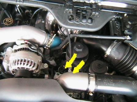
8 Correct Correct The nozzle is mounted using its external 1/8 NPT threads. Tighten the nozzle and nozzle holder assembly one half turn past finger tight using E6000 sealant to seal the threads. Note that the nozzles can be mounted almost anywhere at or before the inlet to the intake. They must be located after the turbo and intercooler however. Ideal locations are usually immediately before the intake itself on the tube coming from the intercooler outlet. Ensure that the nozzle has a clear spray pattern into the airflow, and that the tip of the nozzle is flush with the inner wall of the pipe or protruding slightly into the airflow. Dodge Applications: 5.9L Cummins:

9 6.7L Cummins: Nozzles are mounted in the cast intake elbow located on the driver s side of the engine. This elbow houses the EGR valve, EGR throttle plate, and the MAP sensor. Recommended location is after the EGR throttle plate indicated by arrow in photo. Tip: It is recommended that the cast elbow be removed before drilling and tapping. Tip: Mount nozzles in the middle of the elbow on the front side approx 3 apart so spray is 90º to airflow. Tip: To make sure there is no pooling of fluid while injecting, make sure nozzle tip is at least flush with the inside of the elbow when tightened.


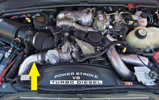
10 Ford Applications: 6.0L Powerstroke: 6.4L Powerstroke: 6.7L Powerstroke: 7.3L Powerstroke


11 GM Applications: LB7, LLY, LBZ LMM

12 2011-Up LML

13 Nozzle/Solenoid/Check Valve (Quick Connect Kits) Solenoids are flow directional. Be sure to note which port is the INLET/PRESSURE port (2 or IN) and which is the OUTLET port (1 or OUT). The main outlet line coming from the Reservoir connects to the first solenoids inlet. The outlet of this solenoid connects to the inlet of the pump. The outlet of the pump connects to the Union T. One outlet of the tee goes to the small nozzle and the other outlet of the tee connects to the second solenoid inlet. The outlet from the second solenoid will connect to the larger nozzle. Measure the distance from the pump outlet to the injection location. Cut the ¼ red tubing using utility knife. Make cuts as square as possible. Ensure there are no kinks in the tubing and insert tubing into quick disconnects until fully seated. Gently pull on tubing to ensure a good connection. Use tie wraps to help route tubing and to ensure it doesn't contact moving or hot parts in the engine compartment. The check valve assembly will ensure that boost pressure does not back-feed air into the system or siphon due to engine vacuum. Ensure the check valve is installed with the arrow pointing in the direction of flow. The Check valve will be installed between the pump outlet and T fitting. Install check valve as close to T fitting as possible. Quick Connect Kits Only- Fit the NPT thread to push connect adapters in both sides of the check valve using E-6000 sealant on the threads. Press the high pressure tubing in each fitting, ensuring the check valve is oriented properly in the direction of flow.

14 Nozzle and Solenoid Connection (Braided Line Kits) Solenoids are flow directional. Your solenoids come pre-installed on a distribution block. Before installing on vehicle remove all NPT threaded fittings and install E6000 sealant on threads / re install. Typical install locations are on firewall of vehicle within 2 feet of nozzle locations. Use supplied self-tapping screws/washers to install in desired location. The pump outlet connects to the 20 section of braided line and then to the check valve inlet. Using the 2 sections of braided line connect both the distribution block outlets to the nozzle holder fittings in intake. Install EGT Probe Drill and tap (1/8-27 NPT Tap, 11/32 pre-drill) exhaust manifold preturbo. Remove manifold prior to drilling. Mount the Temp Probe using the compression fitting (provided). Dodge Applications:


15 Ford Applications: 6.0L/6.4L Powerstroke: The EGT probe can be mounted in the bend on the driver s side exhaust manifold. 6.7L Powerstroke: 6.7L EGR tube mount. Temp probe must protrude into exhaust. Do not kink probe or use pliers to bend. Mount the Temp Probe using the 3/16 compression fitting (provided).
.")

16 7.3L Powerstroke: The EGT probe can be mounted in the drivers side exhaust manifold preturbo. Mount the Temp Probe using the 3/16 compression fitting (provided). GM Applications: Drill and tap exhaust manifold pre-turbo. If this is performed with the exhaust manifold still on the engine, start the engine and let it idle while drilling and tapping. This will prevent shaving from entering the exhaust and turbo. During tapping, coat tap with heavy grease so it will collect any metal shavings.

17 The passenger side exhaust manifold can be reached by removing the inner fender skirt, and accessing through the fender well.

18 Stage 3 Controller Installation Attach controller to secure location with easy access in driver s compartment using supplied tape. Install brass hose barb into intake tubing 3 prior to nozzles. Connect black silicone tubing from brass hose barb to clear tubing coming from the controller and secure with a tie wrap. CAUTION: Disconnect the negative battery terminal while connecting wires to prevent electrical fire or damage to controller. Connect BLACK to a good ground location. Connect WHITE wire to Pump RED power wire. Connect GREEN wire to one BLACK wire from solenoid. Connect other BLACK wire to ground. Connect RED wire to inline switch and then connect to +12V key on source. Connect GREY wire to second ground location. Wire the Yellow K type temp probe connector to temp probe installed in Step 6 above. The YELLOW wire connects to the POSTITIVE terminal, the RED wire connects to the NEGATIVE terminal of the connector. Connect to the lead from control module. Always have a good electrical ground connection. Poor ground will result in erratic operation.
19 Controller Operation The controller has an LCD display screen that has three display modes, and seven control/setup screen. To control the screen selection, the unit has two operator buttons; one to the left of the screen (button 1) and one to the right of the screen (button 2). Pressing and releasing button 1 will cause the display to change to the next screen. Button 2 is only active in the control/setup screens, and is used to change the current control setting of the setup screen displayed. The system memory will remember the current display setting even if the unit is turned off. The controller will turn on at the last used display setting. READ ONLY MODE The controller has a read only mode and is only indicated on a screen that displays percent of injection. When in Read Only Mode, boost pressure and EGT s will be displayed but the controller will not display or command any percent of injection. Read Only Mode is when you want to use the controller as a gauge only, or to get baseline readings for controller setup. Pressing and holding button 2, then pressing button 1, then releasing both buttons will change the system to read only without changing the display screen. The pump will not activate in read only. All screen display functions will remain active even when the injection is turned off. To get the controller out of read only mode simply repeat the procedure.. Display Screens P Inj T This mode displays Boost Pressure (P), EGT Temperature (T) and the Percentage of Injection (Inj) as three independent bar graphs.
20 Boost EGT This mode displays the Boost Pressure and EGT temperature in PSI and degrees F. Boost EGT This mode displays the Boost Pressure and EGT temperature in BAR and degrees C. PSI DegF %Inj This mode displays the Boost Pressure, EGT Temperature and injection in Standard units. BAR DegC %Inj This mode displays the Boost, EGT and Injection in Metric units PSI DegF This display shows both digital and bar graph readings for Boost Pressure and EGT Temperature in Standard units. Bar DegC This display shows both digital and bar graph readings for boost and EGT in Metric units.
21 Control/Setting Screens Injection Mode Change ======> This is the setup screen for the control mode. Pressing the right button (# 2) will toggle the setting between MPG and Tow. If Tow is selected, the 2-D matrix value for the injection is used. If MPG is selected, boost alone will determine injection. Tow mode is used in loaded or towing situations. MPG injection is used in day to day driving and high-performance situations. MPG Mode Settings MPG Mode Start PSI Up === > MPG MODE START - UP. Pressing and releasing button 2 will increase the injection activation point. This should be set 2psi above your vehicle s unloaded flat land cruising boost. MPG Mode Start PSI Down ===> MPG MODE START - DOWN. Pressing and releasing button 2 will decrease the injection activation point. MPG Mode 100% PSI Up ===> MPG MODE 100% - UP. Pressing and releasing button 2 will increase the maximum injection point. This should be set at your vehicles ½ throttle boost PSI
22 MPG Mode 100% PSI Down ===> MPG MODE 100% - DOWN. Pressing and releasing button 2 will decrease the maximum injection point. Power Mode Start PSI Up ===> POWER MODE START - UP. Pressing and releasing button 2 will increase the Power Mode injection activation point. This should be set to 75% of your vehicles max boost pressure. Power Mode Start PSI Down ===> POWER MODE START - DOWN. Pressing and releasing button 2 will decrease the Power Mode injection activation point. Tow Mode Settings Boost Range Change === > This screen is used to select between LOW, MED, and HI boost mode. For vehicles making 8-18 psig of boost, use LOW mode. For vehicles making psig of boost, use MED mode. For vehicles making 25+ psig of boost, use HI mode. Inj Gain Increase = = > This screen is used to increase the injection gain setting. Pressing and releasing button 2 will increase the gain setting. Changes in gain affect injection in Tow Mode only. 5%-10% changes make a big impact.
23 Inj Gain Decrease = = > This screen is used to decrease the injection gain setting. Pressing and releasing button 2 will decrease the gain setting. Variable Controller Tuning MPG MODE In MPG mode, injection is a commanded by boost pressure only. The MPG mode is meant to inject a small amount of fluid just above your vehicles cruising load state. If combustion quench occurs as evidenced by engine bucking, bogging, or white smoke from the exhaust then too much fluid is being injected too soon. To prevent quench in MPG Mode try the following: Adjust the MPG MODE START point to come on at a higher boost level. Adjusting the 100% point higher will also help reduce quench. Change out MPG MAX nozzle to the next size smaller. If quench occurs when the POWER MODE (Red LED on Controller is ON) activates try each of the following: Toggle to the POWER MODE START point to come on at a higher boost level. Change out POWER MODE nozzle(s) to the next size smaller. An example of a vehicle with a max boost of 30psi and a flat land cruising boost of 8psi should be set up with the following settings: MPG Start 10psi MPG 100% 18psi Power Mode Start 23psi
24 The Stage 3 system is not designed to inject at normal cruising conditions. Injecting constantly will damage the controller and/or pump. For best gains the controller should inject just above cruising boost CAUTION: Prolonged quench may cause lower engine damage over a period of time. TOW MODE In Tow mode, the controller will measure EGTs and boost pressure to calculate the injection rate. Based on these two inputs, the controller uses pre-mapped 2-D matrix to determine how much fluid to inject. Because the controller is pre-programmed, there are no start and full points to adjust. If combustion quench occurs as evidenced by engine bucking, bogging, or white smoke from the exhaust then too much fluid is being injected too soon. To prevent quench in TOW Mode try the following: Make sure the boost range is set to your vehicles towing boost range. Low 8-18psi Med 18-25psi Hi 25+ psi Adjust the gain down in 5-10% increments until quench no longer occurs. An example of a vehicle with a max boost of 25psi while towing should be set up with the following settings: Boost Range Gain 100% Med

25 Testing the Injection System Disconnect pump command wire from controller. Using a 12 volt source, apply power to red wire of pump. Pump should activate and fluid level in tank should go down. It is recommended to also check the nozzle spray pattern while following this procedure. Also check for leaks. If pump goes on and fluid level doesn't go down, check hose routing, fluid level. Activation of pump for short periods (2-5 sec.) will purge air bubbles after installation. This can be accomplished during initial use. Testing the Controller With tube removed form the nozzle, place the controller in boost only mode by selecting MPG mode. Set start at 5psig and full at 6psig. Disconnect the silicone boost line from the T fitting on the intake boost line. Turn key on and ensure arming switch on. Using a hand pump, apply psig of pressure to the boost line going to the controller. Pump should activate, fluid should flow, and tank level should go down.
26 Quench Frequently Asked Questions If combustion quench occurs as evidenced by engine bucking or white exhaust smoke, reduce amount of fluid that is being injected. This can be done by: Check your settings. Using a smaller nozzle(s). If quench is in Tow Mode use Screen 9 and Screen 10 to adjust the gain. Injection before the motor is at operating temperature or when the ambient temperature is below 40 F could result in quench and reduced overall performance. What Fluid to Use 100% Water - Will cool combustion and EGTs and will increase power approx HP. How Much Fluid Will I Use? Every application is different but typical fluid usage is: 1 Gallon of fluid per 150 miles with no load 1 Gallon of fluid per 75 miles towing 15,000 lbs
27 My System Injects All the Time Check your settings, if you have the start point set to low, the system will inject more than it is designed. Check your ground(-) connection. Make sure that the 12v positive(+) to the controller is on a switched power source. What Maintenance Do I Need To Do? The only recommended maintenance is to remove nozzle(s) and clean screen filters at least once per year using carb cleaner. Install Notes For future reference it is a good idea to record install notes. This is great if you need technical support, or need to order replacement parts in the future. Nozzle Sizes Controller Settings MPG Start PSI MPG 100% PSI Power Mode Start PSI Boost Range Injection Gain %
28 Disclaimer Do not use this product until you have carefully read the following agreement. This sets forth the terms and conditions for the use of this product. The installation of this product indicates that the BUYER has read and understands this agreement and accepts its terms and conditions. Performance products by their nature are designed to increase horsepower and performance not engineered in the original vehicle and the increased stress could result in damage to related systems. This is a high performance product use at your own risk. Snow Performance Inc., Its agents, employees or owners shall not be under any liability whether in contract or otherwise whether or not resulting from our negligence or contents of information supplied for any damage or loss resulting from such information. The BUYER is responsible to fully understand the capability and limitations of his/her vehicle according to manufacturer specifications and agrees to hold the SELLER harmless from any damage resulting from failure to adhere to such specifications. The SELLER disclaims any warranty and expressly disclaims any liability for personal injury or damages. The BUYER acknowledges and agrees that the disclaimer of any liability for personal injury is a material term for this agreement and the BUYER agrees to indemnify the SELLER and to hold the SELLER harmless from any claim related to the item of the equipment purchased. Under no circumstances will the SELLER be liable for any damages or expenses by reason of use or sale of any such equipment. The BUYER is responsible to obey all applicable federal, state, and local laws, statutes, and ordinances when operating his/her vehicle, and the BUYER agrees to hold SELLER harmless from any violation thereof. The SELLER assumes no liability regarding the improper installation or misapplication of its products. It is the installer's responsibility to check for proper installation and if in doubt, contact the manufacturer. Warranty Snow Performance 1-Year Warranty Policy: Snow Performance, Inc. warrants that the Product shall conform to and perform in accordance with published technical specifications and shall be free of defects in materials and workmanship for 1-year providing: 1. You are the original purchaser and provide proof of purchase. 2. The system was purchased from a Snow Performance Authorized Dealer at MRP pricing set by Snow Performance.* *No warranty will be offered for any Snow Performance products if purchased below MRP. For MRP pricing of your product check 3. An RMA # has been attained and is displayed on package containing returned part. 4. Parts Warranty ~ 90 day warranty on parts purchased separately if used in conjunction with a Snow System. No warranty implied if used with a non-snow part/system. Subject to Snow s inspection of the product, Snow will remedy defects in materials and/or workmanship by repairing or replacing, at Snow s option, the defective product without charge for parts or labor, subject to the limitations and exclusions described in this warranty. This warranty does not cover problems caused by normal wear and tear including aesthetic oxidation of surfaces, accidents, unlawful vehicle operation, or modifications or repairs to
29 product not performed or authorized by Snow. This includes any product that is disassembled or taken apart for any reason. In addition, this warranty does not cover problems resulting from conditions beyond Snow s control including, but not limited to, theft, misuse, overloading, or failure to assemble, mount or use the product in accordance with Snow s written instructions or guidelines included with the product or made available to the original retail purchaser. In the event of failure, Snow will repair or replace the part at Snow's sole discretion. Failures resulting from misapplication or misuse of the Product, failure to adhere to any specifications or instructions, or failure resulting from neglect, abuse, accidents, or act of nature are not covered under this warranty. Warranty service may be obtained by ing tech@snowperformance.net with a copy of your purchase invoice for the product, getting an RMA (Return Merchandise Authorization) number, and delivering the part to Snow. Customer agrees to insure the Product or assume the risk of loss or damage in transit, to prepay shipping charges to Snow, and to use the original shipping container or equivalent. Shipping for Warranty replacement parts shipped outside the continental US will be charged to customer. Non-Warranty Repair/Retest Products returned due to damage or misuse and Products retested with no problem found are subject to repair/retest charges. Product will be returned to customer at customer s expense. A credit card number must be provided in order to obtain an RMA (Return Merchandise Authorization) number prior to returning Product. Distributor/Dealer Warranty: All customers/dealers must deal directly with Snow Performance to receive warranty. No warranty will be issued through a distributor for any reason. Return Policy: All returns must be called in for RMA #. Snow Performance will not take used kits or parts for refund. If you are returning an unused kit there is a 15% restocking fee minus shipping/handling. All returns must be made within 30 days of purchase date. No exceptions. LIMITATION OF LIABILITY: REPAIR OR REPLACEMENT OF A DEFECTIVE PRODUCT IS THE ORIGINAL RETAIL PURCHASER S EXCLUSIVE REMEDY UNDER THIS WARRANTY. DAMAGE OR INJURY TO THE ORIGINAL RETAIL PURCHASER, TO HIS OR HER VEHICLE, CARGO, OR PROPERTY, AND/OR TO ANY OTHER PERSON OR PROPERTY IS NOT COVERED BY THIS WARRANTY. THIS WARRANTY IS EXPRESSLY MADE IN LIEU OF ANY AND ALL OTHER EXPRESS WA RRANTIES, WHETHER ORAL OR WRITTEN. SNOW S SOLE LIABILITY IS LIMITED TO THE REMEDY SET FORTH ABOVE. IN NO EVENT WILL SNOW BE LIABLE FOR ANY DIRECT, INDIRECT, CONSEQUENTIAL, INCIDENTAL, SPECIAL, EXEMPLARY, OR PUNITIVE DAMAGES OR FOR ANY OTHER DAMAGES OF ANY KIND OR NATURE (INCLUDING, BUT NOT LIMITED TO, LOST PROFITS OR LOST SALES). SOME STATES DO NOT ALLOW THE EXCLUSION OR LIMITATION OF INCIDENTAL OR CONSEQUENTIAL DAMAGES, SO THE ABOVE LIMITATIONS MAY NOT APPLY TO YOU. Non-Warranty Repair/Retest Products returned due to damage or misuse and Products retested with no problem found are subject to repair/retest charges. Product will be returned to customer at customer s expense. A credit card number must be provided in order to obtain an RMA (Return Merchandise Authorization) number prior to returning Product.
30 Notes The contents of this document are subject to change without prior notice. No part of or this entire document may be reproduced in any form without prior written permission of Snow Performance, Inc under the copyright except for private use.
INSTALLATION INSTRUCTIONS Diesel Stage 2 Boost Cooler WATER-METHANOL INJECTION SYSTEM
 INSTALLATION INSTRUCTIONS Diesel Stage 2 Boost Cooler WATER-METHANOL INJECTION SYSTEM orporated CAUTION You must completely read through these instructions before installing and operating this product.
INSTALLATION INSTRUCTIONS FOR PART #48003 WATER / METHANOL INJECTION SYSTEM CHEVY/GM DURAMAX 6.6L DIESEL. 2005, Snow Performance, Incorporated
 INSTALLATION INSTRUCTIONS FOR PART #48003 WATER / METHANOL INJECTION SYSTEM CHEVY/GM DURAMAX 6.6L DIESEL orporated CONTENTS Kit Contents...3 Introduction...4 Nozzle Identification Chart:...4 Installation
INSTALLATION INSTRUCTIONS FOR PART #48003 WATER/METHANOL INJECTION SYSTEM 6.6L Duramax Diesel
 Contents: INSTALLATION INSTRUCTIONS FOR PART #48003 WATER/METHANOL INJECTION SYSTEM 6.6L Duramax Diesel Parts List...3 Introduction...4 Installation Mechanical...4 Testing Pump and Mechanical System...8
INSTALLATION INSTRUCTIONS FOR PART #49002 WATER/METHANOL INJECTION SYSTEM Dodge Cummins Diesel 5.9L
 Contents: INSTALLATION INSTRUCTIONS FOR PART #49002 WATER/METHANOL INJECTION SYSTEM 94 06 Dodge Cummins Diesel 5.9L Parts List...3 Introduction...4 Installation Mechanical...4 Testing Pump and Mechanical
INSTALLATION INSTRUCTIONS FOR PART #20011 WATER/METHANOL INJECTION SYSTEMS FOR USE WITH ALL MAF SENSORS
 CONSEQUENTIAL DAMAGES, SO THE ABOVE LIMITATIONS MAY NOT APPLY TO YOU. Non-Warranty Repair/Retest Products returned due to damage or misuse and Products retested with no problem found are subject to repair/retest
INSTALLATION INSTRUCTIONS FOR PART #20010 SRT-4 WATER / METHANOL INJECTION SYSTEM FOR ALL DODGE NEON SRT-4
 Contact Us: Phone Office (719) 633-3811 Fax (719) 633-3496 Tech Support Line (Toll Free) (866) 365-2762 Web http://www.snowperformance.net Email sales@snowperformance.net customerservice@snowperformance.net
Diesel Installation Instructions
 Diesel Installation Instructions Note: please read instructions completely before installation to ensure a safe/easy installation. Installation is broken down in 3-parts. 1. Pump/Tank/Nozzle - (mechanical)
INSTALLATION INSTRUCTIONS FOR PART #20011WRX WATER / METHANOL INJECTION SYSTEM FOR ALL SUBARU WRX/STI
 Contact Us: Phone Office (719) 633-3811 Fax (719) 633-3496 Tech Support Line (Toll Free) (866) 365-2762 Web http://www.snowperformance.net Email sales@snowperformance.net customerservice@snowperformance.net
INSTALLATION INSTRUCTIONS FOR PART #20020 WATER / METHANOL INJECTION SYSTEMS. 2005, Snow Performance, Incorporated
 INSTALLATION INSTRUCTIONS FOR PART #20020 WATER / METHANOL INJECTION SYSTEMS orporated CONTENTS Kit Contents...3 Introduction...4 Installation Mechanical...4 Installation Mechanical...5 Installation -
CAUTION
 Contents: INSTALLATION INSTRUCTIONS FOR PART #20013 WATER/METHANOL INJECTION SYSTEMS For use on: 86 91 Buick Grand National 89 Pontiac Firebird-Turbo 86 92 Toyota Supra MA70 Parts List...3 Introduction...4
INSTALLATION INSTRUCTIONS FOR PART #20011WRX WATER / METHANOL INJECTION SYSTEM FOR ALL SUBARU WRX/STI
 Kit Contents INSTALLATION INSTRUCTIONS FOR PART #20011WRX WATER / METHANOL INJECTION SYSTEM FOR ALL SUBARU WRX/STI Parts o o o o UHO Pump (Ultra High Output) 20 ft High Pressure Tubing 3 ft Wire Loom 3Qt
INSTALLATION INSTRUCTIONS FOR PART #20130 MUSTANG STAGE 3 BOOST COOLER WATER/METHANOL INJECTION SYSTEM
 INSTALLATION INSTRUCTIONS FOR PART #20130 MUSTANG STAGE 3 BOOST COOLER WATER/METHANOL INJECTION SYSTEM Parts List o o o o o UHO (Ultra High Output) Pump 10 ft. 1/4 OD Tubing 3ft. Black Wire Loom 18 1/8
GDP STREET-GATE 38mm Wastegate System
 Installation Manual STREET-GATE 38mm Wastegate System P/N SG67-38MM-7510 GDP STREET-GATE 38mm Wastegate System 07.5-10 DODGE CUMMINS Installation Instructions STREET-GATE 38mm Wastegate Kit p/n SG67-38MM-7510
Average Install Time: 4-6 Hours
 Water/Methanol Stage 1 Instructions Read all Instructions before beginning!!!! Caution EXTREME DANGER Caution Do not use or mix any other manufacturer s products with any Nitrous Express products. Do not
Twin Turbo Installation Instructions
 Twin Turbo Installation Instructions Pacific Performance Engineering 303 N Placentia Ave. Fullerton, CA 92831 www.ppediesel.com Legal in California only for racing vehicles which may never be used on the
½ DODGE CUMMINS OEM BYPASS LIFT PUMP KIT Installation Instructions Part #
 29 July 2005 2003-04.5 Dodge Cummins OEM Bypass Lift Pump Kit # 1050227-1 - 2003-04½ DODGE CUMMINS OEM BYPASS LIFT PUMP KIT Installation Instructions Part # 1050227 PLEASE READ ALL INSTRUCTIONS CAREFULLY
Dodge Ram 5.9L Cummins LOW FUEL PRESSURE ALARM LIGHT - Installation Manual -
 29 September 2005 Dodge Cummins Low Fuel Pressure Alarm Light Kit 1081130-33 1 1999-2005 Dodge Ram 5.9L Cummins LOW FUEL PRESSURE ALARM LIGHT - Installation Manual - Part Number Sequence: 1081130 Red 1081133
DODGE CUMMINS Arctic-Heat Grid Relocation Kit
 Installation Manual P/N 07509-350-GRK 2007.5-09 DODGE CUMMINS Arctic-Heat Grid Relocation Kit Installation Instructions P/N 07509-350-GRK GDP Arctic-Heat Grid Heater Installation PLEASE READ ALL INSTRUCTIONS
L DODGE CUMMINS MK-2 + BLK APPS Mount
 Installation Manual P/N MK20305-APPS 2003-05 5.9L DODGE CUMMINS MK-2 + BLK APPS Mount Installation Instructions P/N MK20305-APPS 2 Micron + Big Line Kit APPS Mount Installation PLEASE READ ALL INSTRUCTIONS
20250 Module Installation Guide
 20250 Module Installation Guide 2013.5-2017 RAM 6.7L Cummins Up to 90HP Gain 1-3 MPG Fuel Savings AgDieselSolutions.com Adjustable switch connector Power +12 volts (Red wire) & Ground (Black wire) Injector
GM 6.6L Duramax. Up to 90HP Gain. AgDieselSolutions.com
 21700 Module Installation Guide 2017 GM 6.6L Duramax *L5P* Up to 90HP Gain 1-3 MPG Fuel Savings AgDieselSolutions.com Adjustable Switch Female Fuel Pressure Sensor Connector Male Fuel Pressure Sensor Connector
CU6703 Module Installation Guide
 Up to 30% More Horsepower 10-20% Fuel Savings Cummins 6.7L Tier III Engines CU6703 Module Installation Guide AgDieselSolutions.com MAP sensor male and female connectors. Power and Ground wires. Module
BD SUPER B SPECIAL Dodge 5.9L Cummins 24v ISB
 1 This turbo is intended for high performance applications and is not to be used for towing applications BD SUPER B SPECIAL 1994-2002 Dodge 5.9L Cummins 24v ISB Part# 1045120 PLEASE READ ALL INSTRUCTIONS
DODGE CUMMINS 24V ISB OEM BYPASS LIFT PUMP KIT Installation Instructions Part #
 2/15/2006 2000-2002 Dodge Cummins OEM Bypass Lift Pump Kit # 1050229-1 - 2000-02 DODGE CUMMINS 24V ISB OEM BYPASS LIFT PUMP KIT Installation Instructions Part # 1050229 PLEASE READ ALL INSTRUCTIONS CAREFULLY
Attitude Instructions Ford 6.0 Powerstroke
 Attitude Instructions Ford 6.0 Powerstroke Attitude 2003, Edge Products Incorporated All rights reserved. Edge Products Incorporated 5875 South Adams Avenue Suite 100 Ogden, UT 84405 (801) 476-3343 www.edgeproductsinc.com
L DODGE CUMMINS Maximizer System
 Installation Manual P/N 07509MAX 2007.5-09 6.7L DODGE CUMMINS Maximizer System Installation Instructions P/N 07509MAX GDP Big Line Kit Installation PLEASE READ ALL INSTRUCTIONS BEFORE BEGINNING INSTALLATION
DODGE CUMMINS GDP Big Line Kit
 Installation Manual P/N 9852BLK 1998.5-2002 DODGE CUMMINS GDP Big Line Kit Installation Instructions P/N 9852BLK GDP Big Line Kit Installation PLEASE READ ALL INSTRUCTIONS BEFORE BEGINNING INSTALLATION
RACE PPE Manifolds and Up-Pipes
 RACE ONLY High-Flow Exhaust Manifolds with Up-pipes GM DURAMAX 6.6L 2001-2015 DISCLAIMER OF LIABILITY This is a performance product which increases horsepower above factory specifications. Additional horsepower
DODGE CUMMINS GDP Twin CP-3 Big Line Kit
 Installation Manual P/N 0306-TCP3 2003-07 DODGE CUMMINS GDP Twin CP-3 Big Line Kit Installation Instructions P/N 0306-TCP3 GDP Twin CP-3 Big Line Kit Installation PLEASE READ ALL INSTRUCTIONS BEFORE BEGINNING
Mega-Rail System Installation
 Installation Manual Mega-Rail System P/N 030767-MRS 2003-2007 DODGE CUMMINS Mega-Rail System Installation Installation Instructions GDP 03-07 Mega-Rail System P/N 030767-MRS PLEASE READ ALL INSTRUCTIONS
DODGE CUMMINS MK-2 Micro-Kleen System
 Installation Manual P/N MK20306 2003-07 DODGE CUMMINS MK-2 Micro-Kleen System Installation Instructions P/N MK20306 2 Micron Fuel Filter Installation PLEASE READ ALL INSTRUCTIONS BEFORE BEGINNING INSTALLATION
JD2800 Module Installation Guide
 Up to 30% More Horsepower 10-20% Fuel Savings John Deere 9.0L Tier III Denso Common Rail Engines JD2800 Module Installation Guide AgDieselSolutions.com Ground Terminal Power (+12V constant) Terminal Injector
Installation Instructions for P/N HD Water Injection Kit with 5 Gallon Tank
 Installation Instructions for P/N 30-3111 HD Water Injection Kit with 5 Gallon Tank 2001-2010 6.6L Duramax Diesel Chevrolet Silverado HD: GMC Sierra HD; Chevrolet Kodiak ; GMC Topkick Hummer H-1 Alpha;
DODGE CUMMINS Air-Boss CR Intake Plenum
 Installation Manual P/N 0307-ABIP 2003-07 DODGE CUMMINS Air-Boss CR Intake Plenum Installation Instructions P/N 0307-ABIP GDP Air-Boss CR Plenum Installation PLEASE READ ALL INSTRUCTIONS BEFORE BEGINNING
Dfuser Stage I Power Module DT-466, DT-570, and HT-570
 Dfuser Stage I Power Module DT-466, DT-570, and HT-570 Copyright 2004, 2005, 2006 dfuser.com, LLC. All rights reserved. Page 1 of 6 User Guide What Gain as much as +35HP and 90ft/lbs of torque!, plus improve
15100 Module Installation Guide Mercedes EPA07 w/dpf
 15100 Module Installation Guide 2007-2009 Mercedes EPA07 w/dpf 7.2L Engines Up to 30% HP Gain 10-20% Fuel Savings AgDieselSolutions.com 2007-2009 Mercedes 7.2L Engine Module +12 volts red wire. Ground
30100 Module Installation Guide L
 30100 Module Installation Guide 1997-2006 12.0L Mack Engines Up to 30% HP Gain 10-20% Fuel Savings AgDieselSolutions.com 1997-2006 Mack 12.0L Engine Module +12 volts red wire. Ground black wire Injector
Female Plug. connecting to Fuel Quantity
 **Ag Diesel Solutions recommends replacing the Transorb/Suppressor Diode before the installation of this module*** Red wire = 12V Constant power. Male Plug connecting to Fuel Quantity Valve Black wire
Dodge 24v ISBe
 BD SUPER B 2003-2004 Dodge 24v ISBe (Non 600 motors) Part # 1045230 PLEASE READ ALL INSTRUCTIONS BEFORE INSTALLATION This turbo system is not compatible with an AFE intake system WITHOUT MODIFICATIONS.
Dfuser T/C Lock-Un Lock
 Dfuser T/C Lock-Un Lock Performance Diesel and more! For more information visit our website at: http://www.dfuser.com Page 1 of 6 User Guide This harness overrides and monitors Torque Converter (T/C) lockup
Dfuser T/C Lock Override with LED
 Dfuser T/C Lock Override with LED the bug that has no cure For more information visit our website at: http://www.dfuser.com Page 1 of 7 User Guide This harness overrides and monitors Torque Converter (T/C)
Installation Instructions
 August 04 BD Camplate Installation -1- BD POWER CAMPLATE KIT Installation Instructions PLEASE READ ALL INSTRUCTIONS CAREFULLY BEFORE INSTALLATION. NOTE: Unless this product has been identified with a CARB
Dodge Cummins 5.9L 24 Valve Edge Products EZ Module Installation Instructions & Manual
 1998.5-2002 Dodge Cummins 5.9L 24 Valve Edge Products EZ Module Installation Instructions & Manual OLD P/N s: EZD1000 / EZD1000A / EZD1000B NEW P/N s: 30200 / 30201 2007 Edge Products All rights reserved.
Installation of Triple A-Pillar Pod and 7 Series Diesel Gauges Dodge Ram w/ 12 Valve Cummins Diesel Engine
 Installation of Triple A-Pillar Pod and 7 Series Diesel Gauges 1994-1997 Dodge Ram w/ 12 Valve Cummins Diesel Engine GlowShift strives to provide outstanding technical support, and our technical support
Power Edge Juice Module Ford 6.0 Powerstroke Diesel
 Power Edge Juice Module Ford 6.0 Powerstroke Diesel 2004, Edge Products Incorporated All rights reserved. Edge Products Incorporated 1080 South Depot Dr. Ogden, UT 84404 (801) 476-3343 www.edgeproducts.com
 Product Name: Product Description: Product Number: Comp-Gate40 40mm External TS-0505-1XXX ------------------------------------------------------------------------------------------------------------------------
Cummins N14 Celect & Celect Plus Engine Module. For Agricultural Applications Only. Part # 31200
 1994-2003 Cummins N14 Celect & Celect Plus Engine Module For Agricultural Applications Only Part # 31200 31200_revA Adjustable Switch Agricultural Cummins N14 Engine Module Power and Ground terminals Timing
Mercedes MBE 906/ L & 7.2L Engine Module. Part # Installation Instructions
 1999-2006 Mercedes MBE 906/926 6.4L & 7.2L Engine Module Part # 15000 Installation Instructions 15000_revC 1999-2006 Mercedes 6.4L & 7.2L Engine Module +12 volts red wire. Ground black wire Injector Terminals
Installation Instructions. Application List Dodge 24V PLEASE READ ALL INSTRUCTIONS BEFORE INSTALLATION
 1 BD DODGE CUMMINS 03-055 C O O L - I T I N T E R C O O L E R Installation Instructions Application List 2003-2006 Dodge 24V 1042510 PLEASE READ ALL INSTRUCTIONS BEFORE INSTALLATION KIT CONTENTS: Please
Mechanical Lift Pump System
 Installation Manual FUEL BOSS Mechanical LP P/N FB-03045 2003 2004.5 DODGE CUMMINS FUEL BOSS Mechanical Lift Pump System Installation Instructions Fuel Boss LP System p/n FB-03045 PLEASE READ ALL INSTRUCTIONS
UNLEASH THE POWER. See More at: bullydog.com WITH BULLY DOG PERFORMANCE PRODUCTS. Doc.# BD41001 v1.0.3
 Bully Dog Technologies, LLC is a team built on integrity that is dedicated to leading the vehicle performance industry with an uncompromising code of ethics demonstrated in the soundness of its employees,
INSTALLATION GUIDE: EGR Delete Kit Ford 6.7L Powerstroke`
 INSTALLATION GUIDE: EGR Delete Kit 20 203 Ford 6.7L Powerstroke` ! Not legal for sale or use on pollution-controlled motor vehicles anywhere in the United States. Legal ONLY for off-road competition racing
2004½-2007 Dodge 5.9L Cummins 24v ISBe (600 motors only)
") 31 October 2006 Part # 1045235-1 - BD Supe r B Single 2004½-2007 Dodge 5.9L Cummins 24v ISBe (600 motors only) Part # 1045235 PLEASE READ ALL INSTRUCTIONS BEFORE INSTALLATION. Note: This turbo system is
31 October 2006 Part # 1045235-1 - BD Supe r B Single 2004½-2007 Dodge 5.9L Cummins 24v ISBe (600 motors only) Part # 1045235 PLEASE READ ALL INSTRUCTIONS BEFORE INSTALLATION. Note: This turbo system is
Owner s Manual Ford Powerstroke 7.3 liter CAUTION: THIS IS A HIGH PERFORMANCE PRODUCT. USE AT YOUR OWN RISK.
 Owner s Manual 1994 2003 Ford Powerstroke 7.3 liter CAUTION: THIS IS A HIGH PERFORMANCE PRODUCT. USE AT YOUR OWN RISK. Edge Products Inc distributed by BD Power Evolution FORD Powerstroke 7.3 liter - 1
Forbidden Diesel Performance Ford 6.7L Powerstroke EGR Delete Instructions 6.7L EGR DELETE BY FORBIDDEN DIESEL PERFORMANCE. Page 1
 6.7L EGR DELETE BY FORBIDDEN DIESEL PERFORMANCE Page 1 WARNING REGARDING EMISSIONS LAWS Not legal for sale or use on pollution-controlled motor vehicles anywhere in the United States. Legal ONLY for off-road
JDCR2000 Module Installation Guide
 Up to 30% More Horsepower 10-20% Fuel Savings John Deere 4.5L, 8.1L & 9.0L Tier III Denso Common Rail Engines JDCR2000 Module Installation Guide AgDieselSolutions.com FEMALE FUEL PRESSURE CONNECTOR (FPC)
Dfuser Eighteen-K Plus Power Module the bug that has no cure
 Dfuser Eighteen-K Plus Power Module the bug that has no cure Copyright 2004, 2005, 2006 dfuser.com, LLC. All rights reserved. Page 1 of 6 User Guide What Known as the 18K module, this device is designed
PMD DRIVER RELOCATION KIT For Chevy 6.5L Diesel Trucks
 - 1 - PMD DRIVER RELOCATION KIT For 1994-1999 Chevy 6.5L Diesel Trucks Part# 1036520 -- Installation Instructions -- PLEASE READ ALL INSTRUCTIONS CAREFULLY BEFORE INSTALLATION. - 2 - Kit Contents BD P/N#
Dodge Cummins 5.9L Edge Comp Module Installation Instructions & Manual OLD P/N s: ECD2000, ECD2000A & ECD2000B NEW P/N s: 30300, 30301,
 1998.5-2002 Dodge Cummins 5.9L Edge Comp Module Installation Instructions & Manual OLD P/N s: ECD2000, ECD2000A & ECD2000B NEW P/N s: 30300, 30301, 30301 Table of Contents DISCLAIMER OF LIABILITY 3 LIMITATION
Owner smanual. Banks Big Hoss Intake Manifold System Chevy/GMC Duramax Turbo-Diesel Engines. with Installation Instructions
 Owner smanual with Installation Instructions Banks Big Hoss Intake Manifold System 2001-2007 Chevy/GMC Duramax Turbo-Diesel Engines THIS MANUAL IS FOR USE WITH KITS 42733 Gale Banks Engineering 546 Duggan
Installation Instructions
 1 BD DODGE CUMMINS PERFORMANCE E X H A U S T M A N I F O L D Installation Instructions Application List 1994-1998 12V 1045980 1998½-2002 24V 1045985 PLEASE READ ALL INSTRUCTIONS BEFORE INSTALLATION KIT
DODGE CUMMINS 24V ISB
 6 November 2009 2000-2002 Dodge Cummins FlowMAX Lift Pump Kit # 1050301B - 1-2000-02 DODGE CUMMINS 24V ISB FLOWMAX LIFT PUMP KIT Installation Instructions Part# 1050301B PLEASE READ ALL INSTRUCTIONS CAREFULLY
Dual Fueler Kit Dodge Cummins 6.7L kit w/no pump ( ) package w/pump ( ) Installation Guide
 package w/pump ( ) Installation Guide") Pacific Performance Engineering, Inc. www.ppediesel.com Dual Fueler Kit Dodge Cummins 6.7L 2007.5-2010 kit w/no pump (2130030) 2007.5-2010 package w/pump (2130031) Installation Guide Technical Support
Pacific Performance Engineering, Inc. www.ppediesel.com Dual Fueler Kit Dodge Cummins 6.7L 2007.5-2010 kit w/no pump (2130030) 2007.5-2010 package w/pump (2130031) Installation Guide Technical Support
JBR MAZDASPEED
 Page1 james Barone Racing Aftermarket Parts and Accessories JBR 2007 2009 MAZDASPEED 3 Front Mount Intercooler Piping Kit Installation Instructions for TR8 Intercooler Tooling: o Jack, Jack Stands, Ramps
MODEL NUMBER: MEDIUM DUTY ONBOARD AIR SYSTEM
 MODEL NUMBER: 10003 MEDIUM DUTY ONBOARD AIR SYSTEM IMPORTANT: It is essential that you and any other operator of this product read and understand the contents of this manual before installing and using
L DODGE CUMMINS MK-2 High Flow Fuel Filter Kit
 Installation Manual P/N MK21318-BLK (non-heated) P/N MK21318-BLKH (heated) 2013-2018 6.7L DODGE CUMMINS MK-2 High Flow Fuel Filter Kit Installation Instructions P/N MK21318-BLK (non-heated) P/N MK21318-BLKH
Air-Boss VP Intake Plenum
 Installation Manual P/N 98502-ABIP 98.5-02 DODGE CUMMINS Air-Boss VP Intake Plenum Installation Instructions P/N 98502-ABIP GDP Air-Boss VP Plenum Installation PLEASE READ ALL INSTRUCTIONS BEFORE BEGINNING
Reference Manual FM-200 Series
 Flush Manifold A/P FOR LIQUID LAUNDRY SUPPLY SYSTEMS Reference Manual FM-200 Series Copyright 2004 Nova Controls, Inc. P/N 20-07941-00 Rev. C i P/N 20-07941-00 Rev. C ii P/N 20-07941-00 Rev. C 1 Description
7.3L POWERSTROKE BANJO BOLT KIT Fits L Powerstroke Diesel. Installation Guide
 7.3L POWERSTROKE BANJO BOLT KIT Fits 94-03 7.3L Powerstroke Diesel Installation Guide INSPECT CONTENTS OF THIS KIT THOROUGHLY BEFORE STARTING THE INSTALLATION PROCESS! IF YOU FIND A PROBLEM WITH YOUR PACKAGE:
Installation Instructions for / Universal Water/Methanol Injection Kit
 Installation Instructions for 30-3000 / 30-3001 Universal Water/Methanol Injection Kit WARNING: This installation is not for the electrically or mechanically challenged! Use this system with EXTREME caution!
AEROMOTIVE Part # Subaru Fuel Rails for Top Feed Injectors WRX & STI INSTALLATION INSTRUCTIONS
 AEROMOTIVE Part # 14135 Subaru Fuel Rails for Top Feed Injectors 02-14 WRX & 07-14 STI INSTALLATION INSTRUCTIONS CAUTION: Installation of this product requires detailed knowledge of automotive systems
Dual Fueler CP3 Pump Kit Installation Guide for LB7
 Pacific Performance Engineering, Inc. www.ppediesel.com Dual Fueler Installation Guide Dual Fueler CP3 Pump Kit Installation Guide for LB7 Supplied Parts: 1. Control Module Pulley 9. Oil Filler Tube 2.
6032 Jacksboro Highway, #100 Fort Worth, Tx MADE IN THE U.S.A.
 6032 Jacksboro Highway, #100 Fort Worth, Tx 76135 817-306-2444 888-842-6572 I N S T A L L A T I O N I N S T R U C T I O N S D O D G E 9 8. 5-0 2 MADE IN THE U.S.A. w w w. q u a d z i l l a p o w e r. c
MPG526-L Kayak Stacker Instructions
 MALO LONER REV2 4/16 MPG526-L Kayak Stacker Instructions Installation and Loading Instructions - Please Read Before Beginning Whats included: (2) Kayak Stackers (2) Sets of Mounting Brackets: Upper and
Part# Accessory Power Distribution Module
 7 February 2006 Power Pod (1038800) Page 1 BD Powe r Pod Installation Instructions Part# 1038800 Accessory Power Distribution Module Power Pod Specifications: Eliminate multiple T-taps and splices on OEM
AEROMOTIVE Part # L Mustang Digital FMU INSTALLATION INSTRUCTIONS
 AEROMOTIVE Part # 17113 4.6L Mustang Digital FMU INSTALLATION INSTRUCTIONS CAUTION: Installation of this product requires detailed knowledge of automotive systems and repair procedures. We recommend that
Dual Fueler CP3 Pump Kit Installation Guide for LBZ/LMM
 Dual Fueler CP3 Pump Kit Installation Guide for LBZ/LMM Supplied Parts: 19b 19c 19a 1. Control Module 2. 3/8 Inlet Fuel Line with Attached 1/2 x 1/2 x 3/8 T Connector 3. 5/16 Return Fuel Line with Attached
Double Scull Car Rack User s Manual
 Page 1 Double Scull Car Rack User s Manual Step 1: Attach your double scull car rack to vehicle roof racks We recommend lining up your double scull rack with the towing hooks located underneath your car
Dfuser Eighteen-K Plus Power Module T444E Special Edition the bug that has no cure
 Dfuser Eighteen-K Plus Power Module T444E Special Edition the bug that has no cure Copyright 2004, 2005, 2006 dfuser.com, LLC. All rights reserved. Page 1 of 7 User Guide What This device is designed for
CRANKCASE VENTILATION KIT
 30 October 2008 2004-07 Ford 6.0L CCV Kit 1 BD Ford 2004-2007 6.0L Powerstroke CRANKCASE VENTILATION KIT P/N# 1032175 PLEASE READ ALL INSTRUCTIONS BEFORE INSTALLATION 30 October 2008 2004-07 Ford 6.0L
For electronically controlled E4OD and 4R100 automatic transmissions ** READ ALL INSTRUCTIONS BEFORE INSTALLATION **
 26 August 2005 Ford PressureLoc #1060380 1 BD Ford PressureLoc Installation Manual For electronically controlled E4OD and 4R100 automatic transmissions Part#: 1060380 ** READ ALL INSTRUCTIONS BEFORE INSTALLATION
9/8/ ½-2004 Dodge 5.9L Cummins Flow-MAX Lift Pump Retro Kit # ½ L DODGE CUMMINS. Installation Instructions
 9/8/2008 1998½-2004 Dodge 5.9L Cummins Flow-MAX Lift Pump Retro Kit # 1050302-1 - 1998½-2004 5.9L DODGE CUMMINS RETRO FIT INTAKE PUMP Kit Installation Instructions P/N# 1050302 PLEASE READ ALL INSTRUCTIONS
Complete Raised Rail Roof Rack System SR1098 SR1099
 Complete Raised Rail Roof Rack System SR1098 SR1099 7 kg/15 lbs xx kg xx lbs Max. 68 kg/150 lbs Instructions Max load capacity 68 kg/150 lbs Before you begin, please read the assembly instructions carefully.
Cummins-2004 Dodge Edge EZ Module Installation Instructions and Manual
 Cummins-2004 Dodge Edge EZ Module Installation Instructions and Manual 2004, 2005 All rights reserved. 1080 South Depot Dr. Ogden, UT 84404 (801) 476-3343 www.edgeproducts.com Manual Version 110105 Table
Gasoline Installation Instructions
 Gasoline Installation Instructions Note: please read instructions completely before installation to ensure a safe/easy installation. Installation is broken down in 3-parts. 1. Pump/Tank/Nozzle - (mechanical)
97-03 Volkswagen 1.9L TDI Injector Nozzles
 97-03 Volkswagen 1.9L TDI Injector Nozzles Product Description Part Number.205 Injector Nozzels #44200.216 Injector Nozzels #44201 VW INJECTOR NOZZLES Introduction These instructions outline how to install
 Product Name: Product Description: Product Number: IWG75 Internal Wastegate Actuator TS-06XX-XXXX ------------------------------------------------------------------------------------------------------------------------
Ford 6.4L Powerstroke NEED PHOTO
 I N S TA L L AT I O N GUIDE: Coolant Filter Kit 008 00 Ford 6.4L Powerstroke NEED PHOTO ! DISCLAIMER ) By installing this product onto your vehicle, you assume all risk and liability associated with its
60 PSI Boost Gauge. For Product Numbers: MT-DV01_60, MT-WDV01_60
 60 PSI Boost Gauge For Product Numbers: MT-DV01_60, MT-WDV01_60 Red: 12v Constant (un-switched) Source (+) Orange: 12v Dimmer (switched) Source (+) (optional) White: 12v Ignition (switched) Source (+)
THIS IS A HIGH PERFORMANCE PRODUCT - USE AT YOUR OWN RISK!!!
 9/15/08 6.6 GM Duramax Aurora 5000 Turbo Installation Guide THIS IS A HIGH PERFORMANCE PRODUCT - USE AT YOUR OWN RISK!!! Do not use this product until you have carefully read the following agreement. This
6 November Ford Powerstroke 6.0/7.3L X-Monitor 1 BD X-MONITOR Ford 6.0/7.3L Powerstroke
 6 November 2006 1087200-7210 Ford Powerstroke 6.0/7.3L X-Monitor 1 BD X-MONITOR 1999-2007 Ford 6.0/7.3L Powerstroke I n s t a l l a t i o n M a n u a l Date Purchased Purchased from Installed by READ THIS
AEROMOTIVE Part # INSTALLATION INSTRUCTIONS
 AEROMOTIVE Part # 14102 INSTALLATION INSTRUCTIONS CAUTION: Installation of this product requires detailed knowledge of automotive systems and repair procedures. We recommend that this installation be carried
Crescent Flush Manifold FOR LIQUID LAUNDRY SUPPLY SYSTEMS
 Crescent Flush Manifold FOR LIQUID LAUNDRY SUPPLY SYSTEMS Reference Manual FM-300 Series Copyright 2005 Nova Controls, Inc. P/N 20-08195-00 Rev. B i ii 1 Description Overview The FM-300 series Flush Manifold
ActuLink ABS Module - ABS-MOD-400
 Installation Instructions ActuLink ABS Module - ABS-MOD-400 For more information on the installation and operation of Tuson s towable ABS system, consult the installation and operations manuals for the
INSTALL GUIDE Dodge/RAM 5.7L HEMI
 INSTALL GUIDE 2009-2017 Dodge/RAM 5.7L HEMI TABLE OF CONTENTS 3 GETTING STARTED 3 PARTS LIST 4 INSTALLATION INSTRUCTIONS 4 REMOVING THE STOCK INTAKE ASSEMBLY 6 INSTALLING THE AIR FILTER 7 INSTALLING THE
COLD AIR INTAKE SYSTEM, CIVIC Si,
 COLD AIR INTAKE SYSTEM, CIVIC Si, 2012+ 343-05-0200 PLEASE READ CAREFULLY BEFORE PROCEEDING WITH INSTALL Parts list (Please verify all parts are included in the kit before proceeding with installation)
INSTALL GUIDE Ford F L
 INSTALL GUIDE 2011-2014 Ford F-150 5.0L TABLE OF CONTENTS 3 GETTING STARTED 3 PARTS LIST 4 INSTALLATION INSTRUCTIONS 4 REMOVING THE STOCK INTAKE ASSEMBLY 5 INSTALLING THE AIR FILTER 6 INSTALLING THE HOUSING
 Product Name: Product Description: Product Number: IWG75 Twin Port Twin Port Internal Wastegate Actuator TS-06XX-XXXX ----------------------------------------------------------------------------------------------------------------
HOW TO INSTALL YOUR BOV
 Product Name: Product Description: Product Number: BMW Kompact BOV Kit Model specific BOV Kit TS-0203-1050/TS-0203-1250 ------------------------------------------------------------------------------------------------------------------------
Ford 6.0L Powerstoke Regulated Fuel Return
 Ford 6.0L Powerstoke Regulated Fuel Return ! WARNING REGARDING EMISSIONS LAWS Not legal for sale or use on pollution-controlled motor vehicles anywhere in the United States. Legal ONLY for off-road competition