Ghaziabad. Site No. 1, NO. REV. NO. Page 1
|
|
|
- August Foster
- 5 years ago
- Views:
Transcription
1 Sintech Precision Products Limited C-189/190, Bulandshahar Road Industrial Area, Site No. 1, Ghaziabad (U.P.), INDIA. Ph.: , /38, /21 Fax: INSTALLATION OPERATION AND MAINTENANCE MANUAL FOR SPLIT CASI NG PUMPS CONTROL COPY NO. REV. NO. REV. DATE SPPL/OM/SCS/04 R1 28/07/2014 Page 1
2 WARRANTY: 1. Seller warrants products of its own manufacture and workmanship under normal use and service for one (1) year from date of installation or start up, but not more than eighteen (18) months after date of shipment. 2. Accessories and components not manufactured by seller are warranted only to the extent of the original manufacturer s warranty. 3. No allowances will be made for repair or alteration effected without specific written authorization from seller. 4. Repairs or alteration made with other than genuine SINTECH original equipment parts may VOID the warranty and relieve the seller of all product responsibility. 5. This warranty is VOID unless the purchaser provides protective storage, installs and maintains the equipment in accordance with manufacturer s instruction. 6. Under terms of this warranty, seller shall not be responsible nor liable for: a. Consequential, collateral or special losses or damages. b. Equipment condition caused by fair wear and tear, abnormal condition of use, accident, neglect, or misuse of said equipment. c. Labour charges, loss or damage resulting from supplying of defective part(s) or improper repairs by unauthorized person(s). d. Damage caused by abrasive materials, chemicals, scale deposits, corrosion, lightening, improper voltage or mishandling. NOTE: AS PER THE COMPANY S POLICY OF CONTINUOUS IMPROVEMENT, THE SPECIFICATIONS & DATA GIVEN IN THIS MANUAL ARE SUBJECT TO CHANGE FROM TIME TO TIME WITHOUT NOTICE. Page 2
3 CONTENTS: 1. Introduction Constructional features 4 3. Material of construction Application Receiving and handling pump Temporary Storage Installation Operation Trouble shooting Maintenance Stuffing box Stuffing box with mechanical seal Over hauling Problem analysis Spare parts General information and safety requirements ORDER FORM FOR PUMP SPARE PARTS..68 Page 3
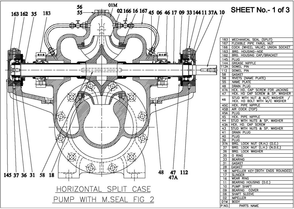
4 General instructions for installation operation and maintenance of SCS pump 1. INTRODUCTION The SCS pumps are designed for specific capacity, speed, pressure and temperature. These pumps are manufactured to close tolerances and rigid specification each and every pump is tested at works for performance and trouble fee operation before dispatch. These are horizontal split casing type pump with suction and discharge nozzles and supporting feet integrally cast in the lower half casing. The construction enables to remove the rotating unit for inspection and repairs by just removing upper half casing, bearing caps and without disturbing alignment or pipe connection or prime mover. (Fig 1 & 2) covered by these instructions. The pump when properly installed and given due care in operation and maintenance should operate satisfactorily for longer period. Our guarantee will be valid only if the installation, operation maintenance and repair of the pumps are carried out in accordance with our instructions. 2. CONSTRUCTIONAL FEATURES Casing: Axially split volute with suction and discharge branches located opposite inline in the lower half. This allows easy removal of the rotating element, without disturbing the pipe work. Pumps required for higher heads have double volute casing to minimum radial thrust. Flanges are drilled as per DIN 2543, 2533 ND 16/ any standards. Impeller: Single entry and double entry, closed type impellers are hydraulically and statically balanced. Shaft: Machined from high quality steel. The shaft is sturdily proportioned to minimize deflection and provide long reliable service. Sleeves: Sleeves are provided to protect the shaft and ensure longer shaft life. Neck Ring: Designed with appropriate clearances and materials to minimize leakages while ensuring a long impeller life. Improved Hydraulics: Unique hydraulic passage design for optimum performance. Stiff Shaft Design: Large diameter shaft supported on a short bearing span minimizes shaft deflection, prolonging seal and bearing life. Simple Maintenance: Standard pumps cartridge bearings and seals can be removed without displacing top half casing. Increased Component Life: More corrosion allowance offers better corrosion protection and optimum lifetime operation. Enhanced Performance: Replaceable wear ring and bush reduce leakage. Increased Efficiency: Standard pumps coating on casing internals optimizes performance and prolongs as new efficiencies. Low Hydraulic Loads: Diametrically opposed volute design reduces hydraulic loads extending seal and bearing life Page 4
5 3. Material of Construction Parts Name All Cast Iron 02s Fitted CF 8 Fitted CF 8M Fitted Bronze Fitted Lower/Upper Cast Iron Cast Iron CF 8 CF 8M Bronze Casing Impeller Cast Iron CF 8 CF 8 CF 8M Bronze Shaft EN 8/SS 410 SS 410 SS 410 SS 316 SS 316 Sleeve SS 410 SS 410 SS 410 SS 316 SS 316 Bearing Housing Cast Iron Cast Iron Cast Iron Cast Iron Cast Iron Casing Wearing Ring Bronze Bronze Bronze Bronze Bronze Other than above state materials pumps are available in Cast Steel, CA 15, NI-Resist, Super Duplex, CN7M, Haste alloy and other special stainless steel alloys. The materials of construction are offered as examples of generally accepted practice, but are not intended as recommendations of fitness for a particular purpose. The customer must determine and take the ultimate responsibility for specifying the proper materials to handle the particular fluid pumped. Unless otherwise specified, all pumps shall be furnished with the standard fitted materials. 4. APPLICATION SINTECH SCS horizontal split case pumps are used in these application 1. Screened/ clear juice 2. Condensate. 3. Cooling water. 4. Water supply 5. Irrigation 6. Fire fighting 7. Industrial systems. 5. RECEIVING AND HANDLING PUMP The pump is dispatched from factory in assembled condition and in crate or in a wooden box specially designed for transport by truck. Upon receipt check the pump usually to determine whether any damage has happened during transpiration or handling. Check especially for these points. A. Broken or cracked equipment including base frame, motor or pump flange and feet. B. Broken motor fan cover, bent eye bolts bent shaft or damaged terminal box. C. Missing Parts. D. Pump shaft rotates freely If any damage or losses have occurred, promptly notify SINTECH representative and the transporters agent, who deliver the pump. When unloading pump units. Lift equally at four points from the base. Do not lift only the driver or pump (Fig 3&4). Care must be exercised in handling particularly the shaft and if bent can cause trouble. Page 5

6 Page 6
7 Page 7
8 Page 8
9 Page 9
10 Page 10
11 Page 11
12 Page 12
13 Page 13
14 6. Temporary storage. If pump is not to be installed and operated soon after arrival, store it in a clean dry place with slow changes in ambient temperature. Protect the pump from moisture, dust, dirt and foreign bodies. During storage following precautions to be taken 1) Ensure that the bearings are packed with recommended grease to prevent moisture from entering around shaft. 2) Ensure that suction and discharge opening of the pumps and other openings are covered with cardboard or other material to prevent foreign objects entering the pump. 3) If pump is to be stored in open or where there is no other suitable covering, cover the unit with tarpaulin or other suitable covering. 4) Rotate the shaft usually every week to prevent corrosion of the bearing surfaces and the stuffing box/shaft seal faces due to moisture. 5) If Pump is to be stored for long time then before installing change the grease/oil and gland packing 7. INSTALLATION All installations should be performed by personnel experienced in placement, alignment and connection of pumping equipment. Before installing the pump clean the suction and discharge flanges. Remove the protecting coating from the pump shaft. If the pump has been in storage remove grease from the bearings and the bearing shaft then be flushed with carbon tetrachloride or kerosene and re lubricated. 7.1 LOCATION 1. Selection of location for pumping unit, which will be clean, well ventilated, properly drained and provides accessibility for installation and maintenance, allow space and head room for the use of overhead crain or hoist sufficiently strong to lift the unit. 2. It some connections of water or liquid are required for flushing cooling, lubrication etc. ensure that they are available for maintenance and inspection. 3. The suction system must provided the pump with net positive suction head (NPSH) equal to or greater than that required by pump. 4. The pump should be located as near to fluid supply as possible so that a short suction pipe can be used so that suction losses are minimum. The discharge pipe should be direct and with as minimum elbow and fitting as possible. 7.2 FOUNDATION A. Prepare the foundation keeping in view the type of soil at site. B. The pump with base frame should be installed on concrete foundation which is strong enough to provide permanent and rigid support for the entire pump. The foundation must be capable of absorbing any vibration, normal strain or shock. As a rule of thumb the weight of the concrete foundation should be 3 5 time the weight of complete pump unit Pouring the foundation Pour the foundation without interruptions to within mm of the final level. Ensure that the concrete is evenly distributed. The top surface of the foundation should be well scored and grooved before the concrete. This set will provide a bonding surface for the grout. Embed foundation bolt in the concrete as shown in (Fig 5) allow enough bolt length to reach through grout, shims, lower base frame, nuts and washer. The foundation should be allowed to cure properly before the base frame is shimmed and grouted. Page 14
15 Page 15
16 7.3. MOUNTING AND LEVLLING A. Lift the base frame on which the pump unit is coupling with the motor should be placed on foundation. B. Disconnects coupling halves. C. Base frame should be supported on metal block or shims or metal wedges having small taper. The support pieces should be placed closed to foundation bolts and midway between bolts (Fig 6). D. Level the base frame by adjusting shims under the base frame. A gap of about 20 mm 40 should be allowed between base frame and foundation for grouting. Check the coupling faces, Suction and discharge flanges for horizontal and vertical positive by means of level. E. Tighten the foundation bolts nuts against the base frame. Make sure that the piping flanges without putting strain on pipes or flanges. F. Machine surface of base frame can be used as reference for leveling purpose. The leveling should be done with help of precision engineer s sprit level. G. Please note that the base Plate Are flexible to some extent and therefore must not be relied upon to maintain the factory alignment. Realignment may be necessary after the complete unit has been leveled on the foundation and again after the grout has set and foundation bolts are tightened. 7.4 ALIGNMENT OF COUPLING The flexible coupling pump & motor is properly alignment with in proper limit on its base plate at the factory. This alignment may be disturbed due to following factors. a) Setting of foundation. b) Deformation of base plate. During transits and/or handling. c) Springing of base frame. d) Piping strain. e) Shift of pump or driver on foundation. f) Wears of the bearing. Grout setting and other reasons. It is therefore essential to check alignment prior to final grouting. A flexible coupling will not compensate for misalignment of the pump and driver its purpose is to allow for temperature changes and to permit independent. Movement of the pump and motor shafts. When the pump and motor shafts are pulled, there should be 3 mm minimum gap between the coupling faces. There coupling should not be used to compensate for excessive misalignment alignment of pump and motor shaft,inaccurate alignment result in vibration and excessive wear of the bearings, shafts and wear rings PROCEDURE FOR COUPLING ALIGNMENT A. Disconnects coupling halves NOTE: before starting work on the pump, make sure that the power supply has been switched off and that it con not be accidently switched on. B. Set the required gap between coupling faces depending upon the coupling size. For a coupling with an outside diameter Note that keyways are 180⁰ displaced. Refer G.A. drawing for proper gap supplied with pump. The coupling gap between faces. Normal Tolerance Page 16
17 Carry out alignment of the motor by placing shims of different thickness under the moto, if possible replace several thin shims with one thick shim There are two forms of misalignment A. Angular: shaft with axes concentric but not parallel. B. Parallel: shaft with axes parallel but not concentric. a. To check for angular alignment insert a pair of inside caliper or a taper gauge at four points at 90.C interval around the coupling (See Fig 7) angular alignment show that all points of the coupling are within mm of each other b. To check parallel alignment place a straight edge across both coupling rims at the top, bottom and both sided (SEE Fig 8) after each adjustment recheck all features all alignment,parallel alignment is correct when the measurement show that all point the coupling faces are within mm of each other 7.5 GROUTING Unless other vise specified, the base frame must be completely filled with grout and the leveling wedges grouted in place. The product warranty may be void if these instructions are not followed. When the alignment is correct the foundation bolts should be tightened evenly. The unit should then be grouted to the foundation. The foundation bolt should not be tightened until grout is hardened, usually 48 hrs after pouring. Grouting compensates for uneven foundation, distributes weight of unit, minimizes vibrating and prevents shifting of unit. Use an approved non shrinking grout and pumping unit should be grouted by experts. The mix required varies with the type of unit to be grouted, location and amount of grout, grout unit as follows. A. Build a form of thick plank around the foundation to contain the grout. B. Sock top of concrete foundation thoroughly then surface water. C. Fill the form with grout up to the top edge of the base frame see (Fig 9). While pouring tamp liberally in order to fill all the cavities and preventing air pockets. D. After the grout has thoroughly has dined tighten the foundation bolts and connect the piping. Ensure that the piping does not exert any strain on the pump flanges. E. Check the alignment after piping is connected and foundation bolts are tightened. If realignment is required, disconnect the piping first then proceed with alignment. reconnect the piping after alignment has been completed and recheck the alignment before connecting the coupling (Fig 10) Page 17
18 Page 18
19 Page 19
20 Page 20
21 Page 21
22 Page 22
23 7.6 PIPING Protective cover is fitted to the suction and discharge flanges to prevent foreign bodies from entering. The pump during transportation and installation and installation. Make sure these covers are removed from the pump before connecting any pipes SUCTION AND DISCHARGE PIPE In order to minimize losses and hydraulic noise in the piping, choose pipe size one or two size higher than the pump suction and discharge size typically flow valuated suction not excess 2m/sec for the suction pipe and 3m/sec for the discharge pipe. Make sure that the NPSH available is higher the NPSH required GENERAL PRECAUTIONS When installing the piping observe these precautions. A. Always run the piping direct to the pump. B. Do not move pump to piping this could make final alignment difficult and cause stress to pump flanges and piping. NOTE: MAKE SURE THAT BOTH SUCTION AND DISCHARGE PIPING ARE INDEPZNDENTLY SUPPORTED NEAR THE PUMP SO THAT NO STRAIN IS TRANSMETTED TO THE PUMP WHEN THE FLANGE BOLTS ARE TIGHTENED C. Install piping as straight as possible and avoid unnecessary bends. Where necessary use 45⁰ or long sweep 90⁰fittings to reduce friction loss. D. Make sure all joint are air tight. E. Where flanged joints are used ensure that inside diameters match properly. F. Remove burr and sharp edges when making joints. G. Make sure that the piping does not cause stress or strain in the pump. H. Always allow sufficient space for maintenance and inspection SUCTION PIPING Locate the pump below system level whenever possible. This will facilities priming, assure a steady liquid flow and provide a positive suction head. NOTE: the sizing and installation of the suction piping is externally important. Many NPSH problems can be avoided with proper installation of suction pipe. The common suction piping installation is shown In (FIG 11A, B, C&D) DISCHARGE PIPING The discharge pipe should be as direct as possible with a minimum of valve and elbow to minimize pipe friction loss. A check valve and a sluice valve should be installed with check valve between the pump and gate valve/ swish valve. The non return valve / check valve protect the pump against excessive pressure and reverse rotation of pump and back flow in case of failure of motor. (Fig 12) In order to minimize frictions losses and hydraulic noise in the pipe work, flow velocity should not exceed 3m/sec in the discharge pipe on long horizontal runs it is desirable to keep the piping as level as possible. Avoid high spots, such as loops as they will collect air and throttle the system or lead to uneven pumping. NOTE: the pump must never be throttled by the use of valve in suction line. The discharge valve is used in priming, starting and when shutting down the pump. Page 23
24 Auxiliary piping connection and gauges In addition to primary piping connection, pump may require connection to the water seal ring and mechanical seal stuffing box drain, discharge and pressure gauge connection all these connected now be installed. (Fig 12A, B & Table given below) SCS PUMP TAPPING CONNECTION CHART Code Description Location of Connection A Gauge Connection Discharge side. On Pump discharge flange side. B Gauge suction side. On suction flange side. C Pump casing drain ON SUCTION SIDE D Pump casing drain On discharge flange side. E Circulation line connection from casing. On pump casing top side. F Drip pan drain On Bearing Housing bottom side. G Vent On top of casing. H Grease cop On bearing housing H1 Grease relief On bearing housing a. Install drain pipe from pump casing and stuffing box to a convenient disposal point. b. Flushing pipes 1. Pumps fitted with stuffing box When suction pressure is below ambient pressure, supply to the stuffing boxes with liquid to provide lubrication and prevent the ingress of air. This is normally achieved via flushing pipe from the pump discharge side to the stuffing; a control valve may be fitted in the flushing pipe to control the pressure to the stuffing box. If the pumped water is dirty and cannot be used for flushing the packing. A separated clean compatible liquid supply to stuffing box at 1 Kg/cm 2 above the suction pressure is recommended. 2. Pumps fitted with mechanical seal Seal requiring recirculation will normally be provided with a flushing pipe from pump casing. To avoid seal damage, we recommend that the supply of any external flushing or cooling liquid is continued after the pump is stopped. Page 24
25 8.6.7 EXTERNAL NOZZLE FORCES AND MOMENTS Steel and alloy steel horizontal pumps and their base plates shall be designed for satisfactory performance if subjected to the forces and moments in table. For horizontal pumps, two effects of nozzle loads are considered distortion of the pump casing and misalignment of the pump and driver shafts. TABLE NOZZLE LOADINGS NOMINAL SIZE OF FLANGE (ND) FORCES (N) Each top nozzle Fx Fy Fz FR Each side nozzle Fx Fy Fz FR Each end nozzle Fx Fy Fz FR MOMENTS (N.m) Each nozzle Mx My Mz MR Page 25
26 KEY 1. SHAFT CENTRELINE 2. DISCHARGE NOZZLE 3. SUCTION NOZZLE 4. CENTRE OF PUMP 5. PEDESTAL CENTRELINE 6. VERTICAL PLANE Coordinate system for forces and moments in table Horizontal pumps with side suction and side discharge nozzles Page 26
27 Page 27
28 Page 28
29 Page 29
30 Page 30
31 Page 31
32 Page 32
33 Page 33
34 8. Operation 8.1 Start up checks. Before starting and after service repair always check the following A. The unit base plate is grouted and bolted to foundation. B. All auxiliary pipe connection and fittings have been completed. C. Before starting the pump, rotate the unit or assembly by hand to ensure rotation of moving part. D. The motor direction of rotation has been checked and correct. E. Before starting the pump, all the guards have been installed around all exposed rotation parts. F. The coupling has been properly aligned between pump and motor. G. Never run the pump dry as the close running fits within the pump are water lubricated, Running dry may result in pump seizure. H. Lubricated bearing with grease if not done. I. Before starting the pump, fill the casing and suction line with liquid. The pump may be primed with ejector or vacuum pump. J. Before starting a mechanical seal pump, turn on the seal water, vent. The seal housing and confirm seal water is at sufficient pressure. K. Before starting a stuffing box pump, adjust the packing gland so that there is sufficient leakage to lubricate the packing and ensure cooling of stuffing box. 8.2 Starting i. Check that suction valve is fully open and discharge and drain valve fully closed. ii. Start the pump; let the prime mover pick up full speed. iii. Open the valve on delivery line slowly. iv. Regulate the required flow by adjusting the delivery valve. v. Open the cock for pressure gauge connection. vi. Turn on seal water to the stuffing box where external water is supplied. 8.3 During running the pump, check the following things and regulate if necessary. A. The pump is running smooth. B. the flow of sealing liquid and cooling/heating water is uninterrupted C. The bearings are not getting heated up abnormally. D. The glands are properly tightened to ensure sufficient leakage to dissipate the heat and control the temperature of gland.the maximum permissible leakage is drops per minutes. E. Check Head and capacity developed by pump F. Check Power Consumption is within limit. G. Ensure that there is no mechanical friction in the pump. H. Check the temperature and vibrations of bearing regularly. If one or the other increases, it may be a sign of improper lubrication or bearing damage. I. Unusual noise from pump should also be investigated and their cause be rectified. 8.4 Stopping the unit 1. Close the discharge valve to prevent the pumped liquid from flowing back. 2. Stop the driver/motor. 3. Close the suction valve. 4. Close the cooling and flushing valve. 5. Successful operation of pump depends on accurate alignment. It is recommended to re check the alignment after prelim in run. Page 34
35 8.5 Bearing operating temperature The pumps are designed to operate a wide ambient temperature range. The bearing temperature, when measured on the outside surface of the bearing housing should normally be around 130⁰F (54⁰c) with ambient of 70⁰F (22⁰C). High speed operation may have higher bearing temperature but these temperature should not exceed 190⁰F (87⁰C). Temperature in excess of 190 F may indicate a lack of lubricant, or bearing problems. It the temperature exceeds 190º F, the pump should be stopped and cause to be investigated and corrective action to be taken accordingly In case of new bearing renew the oil after about 200 hours and then about once a year. If bearing temp is always below 50⁰C and there is only small risk of contamination. If the bearing temperature is up to 80⁰C and if there is damages of contamination the oil should be renewed every six months. 1. Bearing of reputed make equivalent are used. 2. C3 clearance bearing are used. 3. Axial running clearance shall be less than 0.45 mm for all about bearing arrangement. 4. Maximum allowable temp of bearing shall be 80⁰C 5. Bearing are oil lubricated oil level in bearing housing is maintained up to the required level with help of constant level oil indicator. 9. Trouble shooting operating problems If the installation and start up procedures have been followed then pump should provide satisfactory service and long life. However if operating problems do occur, use the following check list to eliminate the most common causes of those problems. A. Insufficient discharge pressure or flow 1. Pump not primed 2. Speed too low, check drive. 3. Discharge heads too high. 4. suction lift too high 5. Wrong direction of rotation. 6. Air leaks into suction piping stuffing box or gasket 7. Impeller passage partially choked 8. Impeller damaged. 9. Impeller running clearance too large. 10. Insufficient suction line submergence 11. Air in liquid 12. Impeller dia. too small 13. Insufficient net positive suction head B. Loss of suction during Operation 1. Suction line leaks. 2. water seal line to stuffing box is choked 3. suction lift too high 4. air or gasses in liquid 5. Air leaks into suction piping, stuffing box or gasket. 6. Wrong direction of rotation. 7. Insufficient suction line submergence. Page 35
36 C. Vibration Or Noise 1. Misalignment between drive and pump 2. Foundation bolts loose or defect in grouting or foundation 3. Mechanical defects a) Shaft Bent b) Rotating element binds 4. Head lower than rating, too much liquid being pumped. 5. Pipe strain improperly supported or aligned. 6. Pump running at shut off condition. 7. Insufficient suction line submergence. 8. Air in liquid. 9. Impeller passage choked. D. Overheating 1. Bearings (a) Excessive grease. (b). Shaft bent. (c). Rotating element binds. (d). Pipe strain. (e). Insufficient bearing lubrication (f). Incorrect type of grease. 2. Packing Box a) Packing gland too tight. b) Water seal line choked. c) Air not vented out of mechanical seal. d) Flushing water not circulating for mechanical seal. E. E. Excessive Power Consumption 1. Speed too high 2. Head lower than rating, too much liquid being pumped. 3. Specific gravity or viscosity of liquid pumped is too high. 4. Mechanical defects a). Shaft bent b). rotating parts binds. 5. Misalignment. 6. System head lower than design. 7. Incorrect diameter of impeller. 10. Maintenance 10.1 Inspection and preventive maintenance requirement For satisfactory operation pump, daily inspection and periodic maintenances are required Daily Checks 2.1 An hourly record of suction and delivery pressure, discharge, input power to pump drive should be maintained. 2.2 bearing temperature, oil level, stuffing box leakage/ stuffing box temperature, cooling water inlet and outlet temperature should be checked and recorded. This gives an idea of mechanical performance of the pump. 2.3 Noise and vibration is the first sign the starting trouble like cavitations, air lock, bearing failure, chocking of Impeller of casing and such other troubles. The pump performance should be checked for noise and vibration. Page 36
37 10.3 Periodical checks 3.1 Temperature of bearing should be measured by a thermometer. Safe maximum temperature a bearing can attain is 80 C 3.2 The lubricants of bearing should be checked. Lubricant might get contaminated with foreign material or get blackened due to overheating. In such a case, bearing should be flushed and cleaned and changed with fresh lubricant. 3.3 Check the stuffing box leakage, Normal leakage should be sufficient to dissipate heat generated. In case the packing s are worn out, all packing rings should be replaced. Replacement of one or two rings or addition of rings should never be done. 3.4 alignment of pump unit should be checked. Due to operational vibration, atmospheric temperature or stress induced by the weight of the piping, the alignment may get disturbed. 3.5 sufficient quantities of suitable lubricant and stuffing box packing should be available in stock for daily and emergency. 3.6 Measuring instrument should be calibrated periodically. 3.7 A guide for preventive maintenance for normal application is given below. Unusual application, dusts etc, and may require more frequent inspection and service. S. No Item Action Required Frequency/ Hours of operation 1 Packing Box Inspect for excess leakage. Adjust and replace packing 150 Hours as necessary/every week 2 Mechanical Seal Replace or clean 2000 hrs or half yearly 3 Pump alignment/check fixing Check for change in Six monthly bolt alignment 4 Vibration and bearing Check for change in Every week temperature Vibration & temp. 5 Bearing Lubricate Every 2000 hrs but at least once a year ANNUAL CHECKS 4.1 The Pump should be overhauled completely to check the clearance and replace worn out parts. Clearance between impeller and casing ring, shaft sleeve and gland/ throat bush, lantern ring and shaft sleeve etc are very important, The bearing should be cleaned and checked thoroughly and lubricated. The stuffing box packing should be replaced and lantern ring should be correctly located. 4.2 The effects of liquid handled on pump components should be checked. If abnormal corrosion, erosion is observed the component should be replaced with that of suitable material. 4.3 The auxiliary pipe line and functioning of the auxiliary system should be checked. The main pipe line should be checked for sealing leakage etc. 4.4 Full running tests may be carried out to check whether there is any fault in the performance in comparison with original performance. 4.5 Piping support should be checked so that pipe does not induce unwanted stress on the pump. Page 37
38 BEARING DETAIL PUMP MODEL Bearing on D.E. side Bearing on N.D.E. side SCS 150x C C3 SCS 150x450A SCS 200x SCS 200x125x C C3 SCS 200x150x C C3 SCS 200x150x C C3 SCS 200x SCS 200x C BECMB C3, 7314 BECBP C3 SCS 200x SCS 200x BG SCS 200x630 NU 317 C BG SCS 250x C C3 SCS 250x C C3 SCS 250x SCS 250x A/C A/C3 SCS 250x250x A/C A/C3 SCS 250x150x540 NU BG SCS 250x BG SCS 250x C C3 SCS 300x SCS 300x ZZ 6314 ZZ SCS 300x BG SCS 300x C C3 SCS 300x ZZ 6314 ZZ SCS 350x ZZ 6314 ZZ SCS 350x C C3 SCS 350x C C3 SCS 350x C C3 SCS 350x SCS 400x SCS 400x C C3 SCS 400x C C3 Bearing temperature: a) Maximum allowable temperature of bearing 80 C b) In case of new bearings, renew the oil after about 200 hours and then about once a year, If the bearing is always below 50 C and there is only small risk of contamination. If the bearing temperature is upto 80 C and if there is danger of contamination, the oil should be renewed about every six months. c) Bearing will be SKF or equivalent make. Page 38
39 Bearing lubrication The lubrication should be confirmed to following grades of grease available in market or equivalent. This grease is acceptable for bearing temp of 5 c to 150 c The bearings are lubricated by grease. Lubrication provides a film between the roller elements and races which reduces the friction and prevents excessive temperature rise of the bearings. The normal life of the bearing is terminated by fatigue only. Improper lubrication practices are the main reason for failure of the bearings. One can follow the following practice. a. Keep lubricant clean, free from dust, rain, moisture, etc., by storing in dust tight container. b. Clean up the lubricant fittings before re lubricating with grease. c. Use clean dispensing equipment. d. Use proper amount of lubricant. If too much lubricant is used it will result in churning and unnecessary power consumption and heat generation. Inadequate lubrication will also cause overheating of the bearings. e. The lubricant should be of correct specification. In case of grease lubrication a good quality lithium ball & roller bearing grease, free from resin & acid and possessing rust preventive properties, should be used. The grease should have a penetration number between Its temperature drop point should not be less than 175ºC. f. The bearing temperature may be allowed to rise 40ºC above room temperature, but should not exceed 80ºC. g. The period of refilling is every 300 hours. h. The grease used could be of following make and grade: Manufacturer Speed 1450 RPM Speed 2900 RPM Indian Oil Servo system 3 Servo system 2 Hindustan petroleum NETRA 3 LITHON 3 ESSO BEACON 2 UNIREX N 3 SHELL ALVANA EPLF 2 LIMONA LX 1 CALTEX STARFAK 3 STAR FAK RE LUBRICATION WITH GREASE The pumps are provided with grease filled in the bearing housing initially. This requires replacing only when it gets contaminated by dust, metal particles, moisture, etc. Re lubricate the bearings as follow: a. Thoroughly clean outside of the bearing housing and grease it. b. Inject clean new grease, forcing out the old grease through the small opening between the shaft and bearing housing. c. Run the pump for a short time to eject any excessive grease. d. Wipe off all excessive grease SEALING & COOLING LIQUID DETAILS The sealing liquid is forced into the gland and lantern ring area by a pressure higher than the pump pressure so that the pump liquid does not came out of gland area. In horizontal split case pumps where the impellers are designed for double entry (suction) the glands are placed on suction side and therefore sealing liquid must have pressure higher than the pump suction pressure. If the required temperature is more than 90ºC the gland region needs cooling. This cooling enhances the lift of gland packing. Please ensure that the sealing liquid is: a. Free from solids b. Compatible with pumping fluid c. Pressure higher than pump pressure (at least 1Kg/cm² higher) d. Flow rate is around 2 to 3 Ltrs. /min FLUSHING OF PIPING SYSTEM When the pump material is of CI or all iron construction, the pump must be thoroughly flushed prior to initial starting to avoid contamination of the piping system. Page 39
40 Cooling of stuffing box bearing housing Cool the gland pack stuffing box when pumping liquid above 80.c Cool mechanical seal stuffing box when pumping liquid temperature above 110.c. The limit is subject to change as per seal manufactures recommendation Quantity of stuffing box cooling water W.R.T. temperature and nominal impeller dia. Meter in mm. Full nominal impeller Cooling pumping Water liquid Quantity at various temperature Dia.mm 80.c 110.c 150.c 200.c 250.c 300.c / / Cooling water quantity mentioned in LPM Maximum temperature of cooling water at outlet 50⁰C Wear ring allowable clearance The pump use radial wearing. The ring should be replaced when the clearance exceeds the values given below or when clearance of pump performance becomes noticeable Diameter of rotating member at clearance Minimum diameter clearance WEAR RING CLEARANCE worn out clearance for replacement Demeter of rotating member at clearance Minimum diameter clearance From To mm. From To mm. < worn out clearance for replacement Page 40
41 CLERANCE BETWEEN SLEEVE & BUSH CLERANCE BETWEEN SLEEVE & BUSH Sleeve OD. Normal clearance Worn out clearance for replacement Stuffing box: Stuffing boxes are gland packed at the factory. All packing is subjected to wear and should be regularly checked generally stuffing boxes in gland pumps should be checked for excessive leakage every 150 hours of operation and gland should be readjusted if necessary. Adjustment is accomplished by lightly tightening gland nuts, and then loosening them so they can be adjusted with finger pressure to allow a small flow of liquid to lubricate the gland packing (30 60 drops per minute). If the flow of liquid has increased and cannot be reduced by lightly tightening of the gland replace the packing and /or shaft sleeve. Note : Do not tighten gland to stop all leakage, leakage is necessary to ensure cooling,flushing and lubrication of the gland packing and to prevent shaft sleeve damage The stuffing box is fitted with lantern /water seal ring.the sealing chamber should be connected to a source of clear, fresh water. The recommended water pressure is 1kg / cm 2 above the maximum discharge pressure. If water is not available, grease lubrication is acceptable Packing replacement Use genuine packing suitable for handling liquid at required temperature, Pumping conditions, and replacement procedure is as under. 1) Stop the pump. 2) Unbolt and remove gland 3) Use a flexible packing tool with hook/ wood screw attachment for removal of the packing and water seal ring. 4) Clean packing box and shaft sleeve. 5) Inspect shaft sleeve for wear or rough finish and replace if necessary. Sleeve should have smooth surface. 6) Install the packing box with new packing and lantern ring in the following order 2 ring packing + 1 lantern ring + 3 rings packing + gland. (FIG 13) 7) For renewing packing rings of suitable quality and dimension. It should be cut clean in an oblique manner, the ends of the ring laid around the shaft should slightly touch. If necessary, measure the ring length on the shaft out Side the pump. 8) Before inserting the turns, clean the gland space. Apply light grease on gland packing and individual rings are to be placed with joints staggered by 90⁰c and are to be pushed backwards with the gland. Consider the sequence as mentioned above for lantern ring. 9) Slightly tighten by hand the gland nuts. During operation carefully tighten nut. The glands need certain time to set. A correctly maintained gland should leak 30 to 60 drops per minute. 10) After prolonged stand still condition of the pump during which the gland may set hardened, they have to be freed by turning shaft by hand. 11) Too excessively tightened gland would result in dry running, heating up, burning of the packing material, and damage to the shaft/shaft sleeve. In such case the shaft with sleeve and gland will have to be replaced. Page 41
42 12) The gland can only be tightened, if the shaft surface is perfect (Ground or polished), the bearing are correct and sleeve are concentric. Maximum eccentricity of about mm to mm depending on size and operating condition is permissible. 13) Packing base data given in table 3 THE GLAND SHOULD NEVER RUN DRY 14) Usual causes of packing failure a. Packing has not been installed properly. b. Packing used is not suitable for the temperature and pressure involved or may be subject to attack by the liquid being handled. c. Inner rings are not properly seated so that the outer rings are carrying the entire load. d. Dust or foreign Material in the stuffing box is causing repaid wear of shaft or shaft sleeve. e. Lantern ring not in line with the tapped hole sealing connection. Page 42
43 TROUBLE CAUSE CURE No liquid delivered Lack of Prime Packing too loose or defective, allowing air to leak into suction. Tighten or replace packing and prime pump. Not enough liquid delivered Air leaking into stuffing box Check that there is some leakage through stuffing box while operatingif no leakage after reasonable gland adjustment new packing may be needed Or Lantern ring may be clogged or displaced and may need centering in line with sealing liquid connection Or Sealing line may be clogged Or Shaft or shaft sleeve below packing may be badly scored and allowing air to be sucked into pump. Defective packing Replace packing and check for surface smoothness of shaft or shaft sleeve. Not enough pressure Defective packing As for preceding Pump works for Air leaks into See proceeding. awhile and quits stuffing box Pump takes too much power Packing too tight Release gland pressure. Retighten reasonably. Keep leakage flowing-if none; check packing, sleeve or shaft Pump leaks Defective packing Replace worn packing. Replace packing damaged by lack of lubrication. excessively at stuffing box Wrong type of packing Replace packing not properly installed or run-in. Replace improper packing with correct grade for liquid being handled. Scored shaft or Put in lathe and machine true and smooth or replace. shaft sleeves Stuffing box Packing too tight Release gland pressure. overheating Packing not Release gland pressure and replace all packing if any burnt or damaged. lubricated Wrong grade of Check with pump or packing manufacturer for correct grade. packing Insufficient cooling Check if supply line valves opened or line clogged. water to jackets Stuffing box Repack improperly packed Packing wears too fast Shaft or shaft Re-machine or replace. sleeve worn or scored Insufficient or no Repack and make sure packing loose enough to allow some leakage. lubrication Improperly packed Repack properly making sure all old packing removed and box clean. Wrong grade Check with pump or packing manufacturer. packing Pulsating pressure on external seal Makes packing move and prevents it taking a 'set'. Remove cause of pulsation. Page 43
44 12. STUFFING BOX WITH MECHANICAL SEAL In general mechanical seal are considered superior to conventional stuffing box packing. In some particular cases, mechanical seals are the only satisfactory way of sealing a centrifugal pump stuffing box. Mechanical seal are particularly recommended where. 1. Leakage must be held to a minimum. 2. Pressure and shaft speed are very high. 3. Corrosive and abrasive condition exits. 4. Volatile inflammable or toxic liquid are being pumped. When specified, these pumps are equipped with mechanical seal Various types of mechanical seal designs are available for sealing centrifugal pump stuffing boxes and are determined by the application with mechanical seal. Tightening is carried by a fixed and rotating ring in a plane perpendicular to the shaft. At least one ring is flexible to compensate for unavoidable constructional in accuracies and the axial misalignment. The sliding surfaces are lapped between the sliding surfaces; a liquid film is formed by the fluid pumped preventing metallic friction and providing for cooling i.e. between the rings When the mechanical seal is functioning satisfactorily without any leakage etc, preventive maintenance is not advised. If leakage occurs a thorough check up is needed. Like other parts in equipment, the mechanical seals are subject to wear at the mating faces of the rotating and stationary ring. The rate of wear will differ with the operation or condition and various other factors such as lubricating properties of liquid being pumped, the presence of impurities in liquid and other operating condition. Before assembly, check up the following points to ensure proper fitting and satisfactory operation of mechanical seal. 1. Shaft sleeve OD should be within +0.00mm or 0.05 mm for specified seal size. 2. Leading edge of shaft sleeve is chamfered. 3. Run out of the shaft at the seal face is within 0.05 mm If the following working conditions are maintained, a Life of several years with a leakage free operation can be obtained. 1. The friction heat generated has to be dissipated. This is done by flushing with the liquid or by cooling the seal. 2. Mechanical damage to the running surfaces should be avoided.damage can be caused by the ingress of solids, especially. Fine dust, by solidification of the fluid between rings, precipitation of solid material by evaporation etc. Avoid dry running, which would destroy the running surfaces very quickly. Dry run is due to operation without fluid, evaporation of the fluid between the sliding ring For Smooth run of the shaft, concentric installation of the seal /gland parts is essential Flushed fluids are different from the fluid being pumped. IF flushing is introduced from an external source, it should be done at minimum pressure of 0.7 kg/cm2 above pressure of liquid at stuffing box. The flushing liquid quantity should be approx 0.3 to 0.5 m3/hr. Flushing at the seal faces is necessary to provide lubrication, heating or cooling of the seal faces and den sing action, Pump should not be run without flushing at the seal face unless recommended by seal manufacturer Page 44
45 12.3 Assembly and disassembly of mechanical seal following procedure apply 1. Certain elastomers are attacked by oil if such parts are used. The shaft must not be lubricated with oil for mounting the ring. It is recommended to grease the shaft with talcum powder or soapy water before installing them. 2. Edges and passages of shaft have to be very carefully rounded off to avoid damaging the lips of elastomers and o ring 3. Protect sliding surfaces from dust (Especially oily dust) and filling from work benches and hands. Touch with only clean hands, Never leave sliding surfaces exposed. Put them only on clean cloth or paper; unpack mechanical seal only at the time of installation. 4. Take care of exact spring tension during installation, Very carefully check developed length 5. Do not grind worn sliding surfaces with each other, separately re machine/ grind surface and lap on a lapping machine. Check plainness 6. The surfaces on which elastomers (o rings, wedge rings) are resting have to be polished. The tolerance specified have to be carefully observed Installation Prior to installation 1. Check surfaces at the face of the seal housing and at the bottom of the seal housing to ensure that they are clean, flat and free from dirt and burrs. The face surface must be smooth to form a good sealing surface for o ring. 2. Check that shaft/shaft sleeve is smooth and free of burrs, nicks and sharp corners that could damage the o ring or shaft packing. When further clean up is required protect the seal remove burse, sharp Carnes by using a strip of emery paper /cloth file threads over the shaft threads, file threads / around the key way with a smooth file, sharp edges must be removed. 3. Remove all chips and dust from the shaft area. 4. Check that all rotary unit parts of the seal fit over shaft. A pre check be made by removing the o ring to the seal and then installing seal on the shaft. Further shaft clean up will be necessary when seal will not pass all the way in seal housing. 5. Remove the seal after the pre check and reinstall the sleeve o ring. 6. Lubricate the shaft and sleeve ID with lubricant recommended by manufacturer. When no lubricant is recommended by mechanical seal manufacture. Use following. 1. Light oil (SAE 10). 2. Silicone lubricant. 3. Soapy water / liquid detergent. Oil based lubricant will damage EPR/ EPDM Elastomer o ring silicon and soapy water are safe for EPR/ EPDM elastomes o rings. 7. Install the o ring between the seal housing and seal. Install seal cover over the shaft and slide into position against the face of the seal box. Take care when passing the sleeve and o rings over the key ways or threads to avoid damaging the o ring. 8. Position seal gland on discharge head seal housing and secure with cap screens. Tighten cap screw gradually and uniformly. Page 45
46 Note 1. Do not pump carbon members against the shaft as they may chip crack or break. 2. Do not over tighten cap screws on gland. This can distort seal seat and cause seal failure 3. Install all seal piping as required prior to making connections of seal liquid pressurizing lines, Make sure seal housing and all sealing liquid lines are flushed free of dust, scale and other particles that would be abrasive to the sealing faces. a. Impeller adjustment is required prior to installation b. Secure collar set screw, set proper spring compression OPERATION 1. The seal should never run dry, even to check for rotation. A Water source must be provided to cool and lubricate faces during pump operation, the lubricating media or external water source. 2. If an external water source is used, it must be clean to within 100 micron and introduced to the seal prior to each motor start Adequate flow must be provided to maintain (15 fps)/ (5 mps) minimum velocity between the bushing and shaft. Refer To the following tab. Shaft or sleeve dia. Mm Flow rate LPM Some seal may swat at initial stage. This condition should cease after a short period as the seal faces lap together. Operate and monitor the seal until leakage subsides. In no case it should exceed 40 drops per minutes. Page 46
47 12.6 Routine maintenance Periodically (100 hours of operation / one week) check seal for leakage. Seal removal Stop the drive and lock out the power so that driver cannot start accidently. 1. Disconnect piping to seal gland 2. Release spring tension to retain proper position. Loosen the collar set screw. 3. Loosen the cap screws securing the gland to the seal housing. Remove seal assembly. 4. Insect all parts of the seal, if any parts show sign of wear, the complete seal should be replaced. Install the new seal as per procedure given above Usual causes of mechanical seal failures and leakage between seal faces 1. Seal faces are worn or scored 2. Gland is bolted up unevenly 3. Stationary insert face is not perpendicular to the axis of shaft 4. The seal ring is binding 5. Wobbling of the rotating seal ring. 6. Cracked or broken stationary seal 7. Shaft run out through stuffing box. 8. Foreign particles between sealing faces 9. Loose set screws 10. Loss of spring compression 11. Mechanical seal is improperly installed. 13. OVER HAULING With Normal operating condition the pump will be due for overhaul annually or after 5000 working hours. This overhauling should do by skilled workers. Please refer cross sectional drawing while dismantling and reassembling the pump DISMANTLING OF PUMP 1. Drain the pump by opening air vent valve and drain plug. 2. Remove all auxiliary pipe fitting 3. Remove all top and bottom flange nuts and locating pin, loosen the gland halves remove gland nuts and gland haves remove gland and ct gland haves /plate. 4. Screw jacking bolt and tap with soft hammer to break seat between lover and upper halt casing and lift off upper half casing (FIG 14) 5. Remove bearing housing cap nuts/ screws and remove bearing housing cap. Match mark bearing housing cap. 6. Tap the inserts with soft hammer and remove rotating unit out of lower half casing. (FIG 15) 7. Check the casing wearing ring clearance for wear. 8. Remove the bearing housing cover from the bearing housing and slide towards impeller as for as possible. 9. Remove the bearing housing by pulling straight off toward end of the shaft from bearing. Page 47
48 10. Remove bearing lock nut and lock washes from NDE side of shaft and using puller, remove the bearing from the shaft. Remove driving end bearing in same way. (FIG 16) CAUTION: Special care for bearings: These instructions do not supercede any information issued by the bearing manufacturers, to whom application should be made for more comprehensive literature by personnel responsible for bearing care who with to make a detailed study. Care and maintenance of bearings is a matter of ensuring that they are : a. Correctly lubricated at intervals as laid down in routing maintenance chart. b. Removed, cleaned and refitted with care. c. Tools used and work areas should be clean. To remove a bearing, use correctly suited withdrawal equipment. Caution: Damage can be caused by exerting force against the outer ring of a ball bearing. Ball bearings should not be dismantled. Clean bearings thoroughly with an approved fluid. Dry the bearings by spinning with dry compressed air or by hand. Do not spin a clean dry bearing. Inspect the bearing for wear, fractures, cracks, corrosion or other damage which may necessitate bearing replacement. 11. Remove packing, lantern ring insert from each side. (FIG 17) 12. Remove two casing rings from the impeller. (FIG 18) 13. Unscrew shaft sleeve from the non driving end (for clockwise rotation of pump) and slide off the shaft. 14. Unscrew shaft sleeve from the driving end (for anticlockwise rotation of pump) and slide off the shaft. 15. Remove impeller; remove the other shaft sleeve and impeller key. a) Clean all components with suitable cleaner and check for damage and wear out. b) Check shaft for straight teness. The maximum allowable run out must be less than mm per meter. (FIG 19) c) Replace all badly worn out parts with new parts, replace all o rings, gaskets, packing mechanical seal etc as required. Page 48
49 Page 49
50 Page 50
51 Page 51
52 Page 52
53 Page 53
54 Page 54
55 13.2 REASSEMLY PROCEDURE 1. Wipe over shaft with clear light oil. 2. Place impeller key into key way. 3. Check impeller for correct rotation and slide on to shaft. 4. Slide and screw shaft sleeve on shaft at both ends. Using spanner lockup tight against the impeller hub. (FIG 21) 5. Slide casing wear ring. (FIG 20) 6. Check o rings, lubricate and roll o rings into groove in each insert. 7. Slide insert and gland simultaneously over shaft with guide at top position. 8. Fit shoulder ring on shaft, then place oil seal into insert. Ensure that no foreign particle should enter in the bearing assembly. 9. Heat the bearing to approximately 100.c (212 f) using bearing or oil bath. (Fig 22) Do not exceed temperature 120.c 10. Slide the heated bearing on to shaft to shoulder ring and place locking washer onto shaft and screw locking nut using hook spanner. Lock up tight against bearing bend the washer in slot of bearing lock nut, cool the bearing to room temperature and fill both sides with 40 gms (approximately) with recommended grease. 11. Fill inside of the bearing housing with grease and slide into place over bearing. 12. Secure bearing housing to insert with four hex head screws. 13. At other end heat the bearing to approx 100.c using bearing heater or oil bath. 14. Slide the heated bearing on to the shaft about shoulder ring. 15. Cool the bearing to room temperature and fill both sides with recommended grease. 16. Fill inside of bearing housing with grease and slide into place over bearing screw bearing housing to insert with four hex head screw. (FIG 22) 17. Place cylindrical pipe in respective position, set the rotation unit in the casing lower half. Locate both insert tongues top. Correct any excessive O ring buckling. Check that the impeller is centralized in the casing and there is no rubbing between impeller and casing. (FIG 23) 18. Insert casing gasket with a light coat of grease on both sides of gasket. Carefully align inner edge of gasket with the insert o rings and casing. 19. Lower the casing half upper into place and engage joint nuts loosely. (FIG 24) 20. Lower the locating pin and drive them in place. 21. Tighten the joint nuts. As per tightening given in table below. (FIG 25) Stud size m 12 m 16 m 20 m 24 Tightening torque 260 kg cm 660 kg cm 1300 kg cm 2250 kg cm. Tighten four corner studs, diagonally opposite first. 22. Install stuffing box flushing pipes. 23. Rotate the shaft by hand to assure smooth turning and that it is free from rubbing. Page 55
56 Page 56
57 Page 57
58 Page 58
59 Page 59
60 Page 60
61 Page 61
62 13.4 INSTALLATION STUFFING BOX PACKING. a) If packing is to be cut from a coil or long length, wrap the packing around dummy shaft, equal to shaft sleeve diameter. b) To assist in cutting rings draw guide lines parallel to the shaft axis and repeated by a distance equal to the packing section may drawn on the spiral. c) Cut the rings from the spiral at an angle of 45⁰ diagonally across the guide lines, no gap in left between the ends. d) Insert the first ring and top it to the bottom of the stuffing box. Each following ring should be installed in the same manner and positioned in the stuffing box so that split is 90 deg a head, e) Install the lantern ring in its proper position to align with the sealing connection. f) When correct numbers of rings have been installed, last packing ring should not project outside the stuffing box face, so that the gland may be properly seated in the stuffing box bore. g) Place the gland follower up securely against the last packing ring and tighten the nuts evenly to give pressure. h) Turn the shaft to ensure it does not bind on the bore. i) Pressurize the stuffing box ensuring that air is not trapped. A packing gland must leak and leakage should take place commencing soon after the stuffing box is pressurized. j) After the pump has been running for minutes with steady leakage, tighten the gland nuts evenly after 5 min interval until leakage is reduced to drops per m a NOTE: EXCESSIVE GLAND PRESSURE WILL CAUSE DAMAGE BY CUTTING OFF LUBRICATION TO THE PACKING AND PACKING WILL BURN AND DAMAGE THE SLEEVE. 14. PROBLEM ANALYSIS S No. No. Cause Remedy 1 Pump not primed lack of priming liquid, incomplete Fill pump and suction pipe completely with pumped liquid. priming. 2 Loss of priming liquid. Mend possible leaks in suction pipe, joints and fillings; vent pump casing to remove accumulated air 3 Suction lift/static lift too high. Reduce the difference in height between the water reservoir/water supply and the pump. 4 Discharge pressure too Make sure that valves in discharge pipe are fully open high. 5 Speed too low. 1. Make sure the motor receives full voltage. 2. Make sure the frequency is correct. 3. Make sure all phases are connected. 6 Wrong direction of rotation. Compare direction of rotation with directional arrow on pump casing If required, change direction of rotation by interchanging two phases in the motor. 7 Impeller completely Dismantle pump and clean impeller. clogged. 8 Suction pipe partially Remove any' obstructions in the suction pipe. blocked. 9 Air leakage in suction pipe Replace or repair defective pipe section or flange or flange. 10 Air leakage in stuffing box. Clean flushing pipe. Replace stuffing box packing rings, if necessary. Page 62
63 11 Cavitations; insufficient NPSH (depending on installation). 12 Impeller or wear rings worn. 1. Increase net positive suction head by placing the pump in a lower position 2. Pressurize suction vessel. Replace impeller and/or wear rings. If necessary, also replace,bearings and shaft 13 Defective packing rings. Replace packing rings. 14 Non return valve too small Replace or clean non return valve. or partially obstructed. 15 Suction pipe not immersed deeply enough. Extend the suction pipe so that the risk of sucking air is eliminated. 16 Impeller diameter too small. Check with factory if a larger impeller can be used; if not, reduce discharge pipe friction losses. But be careful not to seriously overload motor. 17 Obstruction in pump casing. Dismantle pump and remove obstruction 18 Air or gases in liquid. Remove gases or air from pumped liquid. Possibly, see 11) above. 19 The actual duty point of the pump lies to the right of the specified duty point on the pump curve. The result is lower head, higher flow and higher power consumption. 20 Viscosity or specific gravity of pumped liquid is higher than that of water. Install an orifice plate immediately after the discharge flange. The orifice plate will raise the system characteristic/increase the counter pressure thus increasing the head and lowering the flow. The size of the orifice plate must be adapted so that the pressure corresponds to the required duty point Use larger motor. Consult factory for recommended size. Test liquid for viscosity and specific gravity. 21 Shaft bent due to damage. Check deflection of shaft. Total indicator run out should not exceed 0.05 mm. Possibly replace shaft 22 Mechanical failure of bearing and/or impeller. Check bearings and impeller for damage. Possibly replace bearings or impeller. 23 Misalignment. Realign pump and motor 24 Electrical defects. Ensure that voltage and frequency of the power supply are correct. Remedy possible defects in the motor. Ensure that the motor is properly cooled. 25 Speed too high. Ensure that frequency of power supply corresponds to frequency stated on motor nameplate. 26 Foundation not rig id enough. 27 Lubricating oil/grease dirty or contaminated. Retighten foundation bolt nuts. Ensure that the foundation was made according to installation and operating instructions. Clean bearings and bearing housings according to instructions and re lubricate bearings. Page 63
64 15. SPARE PARTS LIST Recommended spare part list for two year normal operation S. No Description 1. Casing half upper 2. Casing half lower 3. Impeller 4. Wearing ring (DE & NDE) 5. Bearing housing (DE) 6. Bearing housing (NDE) 7. Bearing 8. Impeller key 9. Coupling key 10. Lock nut (bearing ) 11. Lock washer (washer) 12. Grease nipple 13. Vent valve 14. Oil seal 15. Set of gasket] 16. Set of o ring 17. Set of screws 18. Set of studs 19. Set of Nuts. 20. Set of Pins. 21. Set of Plug 22. Set of washer 23. Pump shaft 24. Shaft sleeve 25. Gland, stud nut and washer. 26. Insert 27. Deflector 28. Coupling set complete. Page 64
65 GENERAL INFORMATION & SAFETY REQUIREMENTS: 1.0 The products supplied by SINTECH have been designed with safety in mind. Where hazards cannot be eliminated, the risk has been minimized by the use of guards and other design Features. Some hazards cannot be guarded against and the instructions below must be complied with for safe operation. These instructions cannot cover all circumstances; you are responsible for using safe working practices at all times. 1.1 SINTECH products are designed for installation in designated area, which are to be kept clean and free of obstructions that may restrict safe access to the controls and maintenance Access points. A Pump duty Nameplate is fitted to each unit and must not be removed. Loss of this plate could make identification impossible. This in turn could affect safety and cause difficulty in obtaining spare parts. If accidental loss or damage occurs, contact SINTECH immediately. 1.2 Access to the equipment should be restricted to the personnel responsible for installation, operation and maintenance and they must be trained, adequately qualified and supplied with appropriate tools for their respective tasks. 1.3 SINTECH requires that all personnel that are responsible for installation, operation or maintenance of the equipment, have access to and study the product instruction manual before any work is done and that they will comply with all local and industry based safety instructions and regulations. 1.4 Ear defenders should be worm where the specified equipment noise level exceeds locally defined safe levels. Safety glasses or goggles should be worn where working with pressurized systems and hazardous substances. Other personnel protection equipment must be worn where local rules apply. 1.5 Do not wear loose clothing or jewellery which could catch on the controls or become trapped in the equipment. 1.6 Read the instruction manual before installation, operation and maintenance of the equipment. Check and confirm that the manual is relevant copy by comparing pump type on the nameplate and with that on the manual. 1.7 Note the limits of product application permissible use specified in the manual. Operation of the equipment beyond these limits will increase the risk from hazards noted below and may lead to premature and hazardous pump failure. 1.8 Clear and easy access to all controls, gauges and dials etc. must be maintained at all times. Hazardous or flammable materials must not be stored in pump rooms unless safe areas or racking and suitable containers have been provided. 1.9 IMPROPER INSTALLATION, OPERATION OR MAINTENANCE OF THIS SINTECH PRODUCT COULD RESULT IN INJURY OR DEATH. SAFETY INSTRUCTIONS WHILE HANDLING AND STORAGE: When lifting the pump, use the lifting points specified on general arrangement drawing. Use lifting equipment having a safe working load rating suitable for the weight specified. Use suitable slings for lifting pump which is not provided with lifting points. The use of fork lift truck and chain crane sling equipment is recommended but locally approved equipment of suitable rating may be used Do not place fingers or hands etc. into the suction or discharge pipe outlets and do not touch the impeller, if rotated this may cause severe injury. To prevent ingress of any objects, retain the Protection covers or packaging in place until removal is necessary for installation. If the packaging or suction and discharge covers are removed for inspection purposes, replace afterwards to protect the pump and maintain safety. Page 65
66 SAFETY INSTRUCTIONS WHILE ASSEMBLY & INSTALLATION Do not place fingers or hands etc. into the suction or discharge pipe outlets and do not touch the impeller. If rotated this may cause severe injury. To prevent ingress of any objects, retain the Protection covers or packaging in place unit removal is necessary for installation. Do not touch any moving or rotating parts. Guards are provided to prevent access to these parts. Where they have been removed for maintenance they must be replaced before operating the Equipment. Shaft alignment must be checked again after the final positioning of the pump unit and connection to pipe work as this may have disturbed the pump or motor mounting position. If hot liquids (above 80⁰C) are being pumped. Alignment should be checked and reset with pump and motor at their normal operating temperature. If this is not possible, SINTECH can supply estimated initial Offset figures to suit extreme operating temperatures. Failure to support suction and delivery pipe work may result in distortion of the pump casing with the possibility of pump failure. SAFETY INSTRUCTIONS WHILE COMMISSIONING & OPERATION Do not touch any moving or rotating parts. Guards are provided to prevent access to these parts, where they have been removed for maintenance they must be replaced before operating the equipment. Check that the pump is primed. Pump should never be run dry as the pumped liquid acts, as lubricant for the close running fits surrounding impeller and damage will be incurred. Failure to supply the stuffing box mechanical seal with cooling of flush water may result in damage and premature failure of the pump. Do not touch surfaces which during normal running will be sufficiently hot to cause injury. Note that these surfaces will remain hot after the pump has stopped; allow sufficient time for cooling before maintenance. Be cautious and note that other parts of the pump may become hot if a fault is developing. Do not operate water pumps in temperatures below freezing point, without first checking that the pumped fluid is not frozen and the pump is free to turn. Pumps in these environments should be Drained down during inactivity and re primed before starting. In addition to local or site regulations for noise protection, SINTECH the use of personal ear protection equipment in all enclosed pump rooms and particularly those containing diesel engines car must be taken to ensure that any audible alarm or warning signal can be heard with ear defenders worn. Be aware of the hazards relating to the pumped fluid, especially the danger from inhalation of noxious and toxic gases, skin and eye contact or penetration. Obtain and understand the hazardous substance data sheets relating to the pumped fluid and note the recommended emergency and first aid procedures. Page 66
67 SAFETY INSTRUCTIONS WHILE MAINTENANCE & SERVICING Before attempting any maintenance on a pump particularly if it has been handling any form of hazardous liquid. It should be ensure that the unit is safe to work on. The pump must be flushed thoroughly with suitable cleaner to purge away any of the product left in the pump components. This should be carried out by the plant operator and a certificate of cleanliness obtained before Starting work. To avoid any risk to health it is also advisable to wear protective clothing as recommended by the site safety officer especially when removing old packing which may be contaminated. Check and ensure that the pump operates at below the maximum working pressure specified in the manual or on the pump nameplate and before maintenance, ensure that the pump is drained down. Wear a suitable mask or respirator when working with packing and gasket components which contain fibrous material, as these can be hazardous when the fibrous dust is inhaled. Be cautions, if other supplier s components have been substituted for genuine SINTECH parts, these may then contain hazardous materials. Be aware of the hazards relating to the pumped fluid, especially the danger from inhalation of noxious and toxic gases, skin and eye contact or penetration. Obtain and understand the hazardous Substance data sheets relating to the pumped fluid and note the recommended emergency and first aid procedures. Isolate the equipment before any maintenance work is done. Switch off the mains supply remove fuses, apply lock outs where applicable and affix suitable isolation warning signs to prevent inadvertent reconnection. In order to avoid the possibility of maintenance personnel inhaling dangerous fumes or vapors, it is recommended that the maintenance work be carried out away from the pump locations by removal of bearing housing and shaft assembly to a suitable to a suitable maintenance area. Page 67
 A. W.O. B. Model C. S. No. D. M³/HR E. MWC F. Motor kw. G. RPM H. SUC I.")
68 ANNEX 1 ORDER FORM FOR PUMP SPARE PARTS ORDERING INSTRUCTION 1. Date of order / Enquiry. 2. Your reference. 3. Name plate information. (Every pump has the following plate fastened to the Pump providing necessary identification of the Pump.) A. W.O. B. Model C. S. No. D. M³/HR E. MWC F. Motor kw. G. RPM H. SUC I. DEL Image of Name Plate 4. Part Name (Refer to cross section drawing.) 5. Part No. 6. Pump Application. 7. MOC of required Part. 8. Quantity. Page 68
HORIZONTAL SPLIT CASING PUMP
 OPERATION & MAINTENANCE MANUAL HORIZONTAL SPLIT CASING A Mark of Quality CROSS SECTION DRAWING No. DESCRIPTION MATERIAL 01 1/4 BSP PLUG BRASS 02 LOWER HOUSING C. I. IS-210, FG260 03 IMPELLER C. I. / G.
Ghaziabad. Site No. 1, REV. NO. 28/07/2014. Page 1
 www.sintechpumps.com Sintech Precision Products Limited C-189/190, Bulandshahar Road Industrial Area, Site No. 1, Ghaziabad 201001 (U.P.), INDIA. Ph.: +91-120-4176000, 3290637/38, 2866320/21 Fax: +91-120-2867715
Ghaziabad. Site No. 1, UMOR REV. NO. REV. DATE 28/07/2014. Page 1
 www.sintechpumps.com Sintech Precision Products Limited C-189/190, Bulandshahar Road Industrial Area, Site No. 1, Ghaziabad 201001 (U.P.), INDIA. Ph.: +91-120-4176000, 3290637/38, 2866320/21 Fax: +91-120-2867715
INSTALLATION, OPERATION AND MAINTENANCE INSTRUCTIONS
 INSTALLATION, OPERATION AND MAINTENANCE INSTRUCTIONS Contents Section 1. General Observations... 2 2. Operation... 4 3. Control During Operation... 5 4. Trouble Shooting... 6 5. Maintenance... 7 Please
Series Base mounted pump. Installation and operating instructions
 Series 4030 Installation and File No: 40.80 Date: june 25, 2015 Supersedes: 40.80 Date: october 10, 2009 contents General 4 Inspection 4 Installation - Series 4030 base mounted Pump 4 1.0 Location 4 2.0
Series Base mounted pump. Installation and operating instructions
 Series 4030 Installation and File No: 40.80 Date: december 12, 2016 Supersedes: 40.80 Date: july 27, 2016 contents General 4 Inspection 4 Installation - Series 4030 base mounted Pump 4 1.0 Location 4
Installation Vertical Pump: Installation 'CM' and 'CDM' Style: Operation:
 Installation Vertical Pump: Gusher vertical end suction pumps with integral shaft is easily installed and put into service. With the one piece shaft design there is no couplings to align, no shims or no
SERIES PC INSTRUCTION AND OPERATION MANUAL
 MEGGA SERIES PC INSTRUCTION AND OPERATION MANUAL Models PCT and PCF Close-coupled and frame-mounted single-stage horizontal end-suction pumps. WARNING: Read this manual before installing or operating this
Site No. 1, Ghaziabad REV. NO. Page 1
 ` www.sintechpumps.com Sintech Precision Products Limited C-189/190, Bulandshahar Road Industrial Area, Site No. 1, Ghaziabad 201001 (U.P.), INDIA. Ph.: +91-120-4176000, 3290637/38, 2866320/21 Fax: +91-120-2867715
Ghaziabad. Site No. 1, SDV REV. NO. Page 1
 ` www.sintechpumps.com Sintech Precision Products Limited C-189/190, Bulandshahar Road Industrial Area, Site No. 1, Ghaziabad 201001 (U.P.), INDIA. Ph.: +91-120-4176000, 3290637/38, 2866320/21 Fax: +91-120-2867715
PROCESS PUMPS (INDIA) PVT LTD
 PVT LTD") MANUAL: - M10 HORIZONTAL BPO METALLIC PUMP WITH EXTERNAL MECHANICAL SEAL (GROUP- III & IV) INSTALLATION, OPERATION AND MAINTENANCE MANUAL PROCESS PUMPS (INDIA) PVT LTD Plot No.86, III Phase, Peenya Industrial
MANUAL: - M10 HORIZONTAL BPO METALLIC PUMP WITH EXTERNAL MECHANICAL SEAL (GROUP- III & IV) INSTALLATION, OPERATION AND MAINTENANCE MANUAL PROCESS PUMPS (INDIA) PVT LTD Plot No.86, III Phase, Peenya Industrial
KP-C Series. Close Coupled End Suction Centrifugal Pumps. Installation, Operation and Maintenance
 KP-C Series Close Coupled End Suction Centrifugal Pumps Installation, Operation and Maintenance PUMP MODEL NOMENCLATURE KP - 8 x 6 x 16 - E C - AI - BCM Pump Series Suction Pipe Size (in) Discharge Pipe
PROCESS PUMPS (INDIA) PVT LTD
 PVT LTD") MANUAL: - M12 HORIZONTAL BPO METALLIC PUMP WITH GLAND PACKING (GROUP- III & IV) INSTALLATION, OPERATION AND MAINTENANCE MANUAL PROCESS PUMPS (INDIA) PVT LTD Plot No.86, III Phase, Peenya Industrial Area,
MANUAL: - M12 HORIZONTAL BPO METALLIC PUMP WITH GLAND PACKING (GROUP- III & IV) INSTALLATION, OPERATION AND MAINTENANCE MANUAL PROCESS PUMPS (INDIA) PVT LTD Plot No.86, III Phase, Peenya Industrial Area,
MAINTENANCE AND REPAIR INSTRUCTIONS
 MAINTENANCE AND REPAIR INSTRUCTIONS TYPE TH PUMPS Peerless Pump Company Indianapolis IN, 46207-7026 4849357 TABLE OF CONTENTS Maintenance Page 1 & 2 Disassembly Page 5 & 6 Impeller Clearance 3 Reassembly
Maintenance Instructions
 General Note These instructions contain information common to more than one model of Bevel Gear Drive. To simplify reading, similar models have been grouped as follows: GROUP 1 Models 11, 0, 1,, (illustrated),,
 INSTRUCTIONS Your Ampco centrifugal pump is a rugged unit designed to provide years of low cost pumping service. There is a small amount of necessary care required to ensure you of this expected long service.
PROCESS PUMPS (INDIA) PVT LTD
 PVT LTD") HYDRODYNAMIC SEAL NON METALLIC PUMP INSTALLATION, OPERATION AND MAINTENANCE MANUAL PROCESS PUMPS (INDIA) PVT LTD Plot No.86, III Phase, Peenya Industrial Area, Bangalore 560058 Phone: 91-80-28395327/28
HYDRODYNAMIC SEAL NON METALLIC PUMP INSTALLATION, OPERATION AND MAINTENANCE MANUAL PROCESS PUMPS (INDIA) PVT LTD Plot No.86, III Phase, Peenya Industrial Area, Bangalore 560058 Phone: 91-80-28395327/28
TECHNICAL SERVICE MANUAL GENERAL PURPOSE JACKETED PUMPS SERIES 230 MODELS HX4, KK, LQ, Q, M, N
 CONTENTS TECHNICAL SERVICE MANUAL GENERAL PURPOSE JACKETED PUMPS SERIES 230 MODELS HX4, KK, LQ, Q, M, N SECTION 2 BULLETIN TSM-230-V ISSUE A Special Information 2 Maintenance 2 Packed Pump Breakdown Drawing
TECHNICAL SERVICE MANUAL GENERAL PURPOSE BRACKET MOUNTED PUMPS SERIES 115 MODELS G, GX2, H and HX4
 TECHNICAL SERVICE MANUAL GENERAL PURPOSE BRACKET MOUNTED PUMPS SERIES 115 MODELS G, GX2, H and HX4 SECTION 2 BULLETIN TSM-115-C ISSUE A CONTENTS Special Information 2 Maintenance 2 Packed Pump Breakdown
INSTRUCTION AND REPAIR MANUAL MODELS 341A, 342A AND 344A 6
 SECTION 6 ITEM 0 DATED JUNE 1998 SUPERSEDES ITEMS 1, 2, DATED MARCH 1992 INSTRUCTION AND REPAIR MANUAL MODELS 1A, 2A AND A 6 NOTE This repair manual is applicable to pump Models 1A, 2A and A. All photos
End Suction Centrifugal
 M o d e l s 3 U / 3 U B End Suction Centrifugal Operating Instructions, Installation & Maintenance Manual Certified to NSF/ANSI 6, ANNEX G * NSF/ANSI 6 Annex G listed models: 3U EBARA International Corporation
FUNCTION OF A BEARING
 Bearing FUNCTION OF A BEARING The main function of a rotating shaft is to transmit power from one end of the line to the other. It needs a good support to ensure stability and frictionless rotation. The
Principals of Operation... 1 Rotary Vane Priming Pump VPE and VPES... 2 Rotary Vane Priming Pump VPO and VPOS Priming Valve...
 Priming Systems Installation Priming Systems Operation & Maintenance Form No. F 1031 Section 2312 Issue Date 10/07/94 Rev. Date 02/27/06 Table of Contents Illustrations Principals of Operation...........................
GT-200 GATE VALVES PN16, Screwed end
 Document No. : MD-QO-04-281 Date : 2009/07 /17 Version : 1.0 GT-200 GATE VALVES PN16, Screwed end USER MANUAL Modentic Industrial Corporation 14F-1,No.57Taya Rd.,Taichung,Taiwan,R.O.C. Email:modentic@ms9.hinet.net
NECO Pumping Systems
 INSTALLATION OPERATION & MAINTENANCE INSTRUCTIONS For Your NECO Pumping Systems Fuel Oil Transfer System THIS COMPLETELY ASSEMBLED, TESTED, PACKAGED SYSTEM IS OF THE HIGHEST QUALITY AND DESIGN. TO OBTAIN
1750 RPM Centrifugal Pumps
 Please read and save this Repair Parts Manual. Read this manual and the General Operating Instructions carefully before attempting to assemble, install, operate or maintain the product described. Protect
INSTRUCTION MANUAL INTERNAL GEAR PUMP TITAN G-4124A SERIES=> FLANGED TITAN G-124A SERIES => FLANGED MODELS:
 INSTRUCTION MANUAL INTERNAL GEAR PUMP TITAN G-4124A SERIES=> FLANGED TITAN G-124A SERIES => FLANGED MODELS: G-H, G-HL, G-K, G-KK, G-L, G-LQ, G-LL, GLS, G-Q, G-QS 1 Contents Maintenance Thrust bearing adjustment
2.- HANDLING OF VALVES BEFORE ASSEMBLY 3.- FITTING THE VALVE TO THE REST OF THE ASSEMBLY 5.- PERIODICAL INSPECTION OF THE VALVE AND MAINTENANCE
 Page 1 of 16 CONTENTS 1.- INTRODUCTION 2.- HANDLING OF VALVES BEFORE ASSEMBLY 3.- FITTING THE VALVE TO THE REST OF THE ASSEMBLY 4.- OPERATION OF A BALL VALVE 5.- PERIODICAL INSPECTION OF THE VALVE AND
INSTRUCTIONS Installation Operation Repair
 Peerless Pump Company 2005 Dr. M.L. King Jr. Street, P.O. Box 7026, Indianapolis, IN 46207-7026, USA Telephone: (317) 925-9661 Fax: (317) 924-7338 www.peerlesspump.com www.epumpdoctor.com INSTRUCTIONS
PROCESS PUMPS (INDIA) PVT LTD
 PVT LTD") VERTICAL CANTILEVER SHAFT SUMP PUMP (PPCS)_ METALLIC INSTALLATION, OPERATION AND MAINTENANCE MANUAL PROCESS PUMPS (INDIA) PVT LTD Plot No.86, III Phase, Peenya Industrial Area, Bangalore 560058 Phone:
VERTICAL CANTILEVER SHAFT SUMP PUMP (PPCS)_ METALLIC INSTALLATION, OPERATION AND MAINTENANCE MANUAL PROCESS PUMPS (INDIA) PVT LTD Plot No.86, III Phase, Peenya Industrial Area, Bangalore 560058 Phone:
DELTA O-RING CARTRIDGE SEAL ASSEMBLY AND INSTALLATION INSTRUCTIONS INTRODUCTION:
 DELTA O-RING CARTRIDGE SEAL ASSEMBLY AND INSTALLATION INSTRUCTIONS INTRODUCTION: These instructions are provided to familiarize the user with the seal and its use. The instructions must be read carefully
MODEL 442 MODEL 492 INSTALLATION, OPERATION AND MAINTENANCE INSTRUCTIONS HORIZONTAL SPLIT CASE SPLIT CASE FIRE PUMP FOR
 INSTALLATION, OPERATION AND MAINTENANCE INSTRUCTIONS FOR MODEL 442 HORIZONTAL SPLIT CASE & MODEL 492 SPLIT CASE FIRE PUMP TABLE OF CONTENTS PAGE i TOPIC PAGE PUMP IDENTIFICATION.......................................
1750 RPM Centrifugal Pumps
 Please read and save this Repair Parts Manual. Read this manual and the General Operating Instructions carefully before attempting to assemble, install, operate or maintain the product described. Protect
Model 3656/3756. Installation, Operation and Maintenance Instructions. Table of Contents. Owner s Information
 Installation, Operation and Maintenance Instructions Model 656/756 Owner s Information Please fill in information and give this booklet to homeowner. Warranty information is on page 12. Model Number: Serial
DELTA O-RING CARTRIDGE SEAL ASSEMBLY AND INSTALLATION INSTRUCTIONS INTRODUCTION:
 DELTA O-RING CARTRIDGE SEAL ASSEMBLY AND INSTALLATION INSTRUCTIONS INTRODUCTION: These instructions are provided to familiarize the user with the seal and its use. The instructions must be read carefully
Impeller Replacement
 Impeller Replacement Threaded Shaft Frame Mount H 806 Clockwise Rotation Volute shown. 1149 0794 1 Unfasten hardware holding volute to bracket. Remove volute to expose impeller. Peel off old volute gasket
PUMPS STEAM TURBINES BUILDING & FIRE WASTEWATER SERVICE PUMP CLINIC 15 MECHANICAL SEAL DESIGN, OPERATION AND MAINTENANCE PROBLEMS
 PUMP CLINIC 15 MECHANICAL SEAL DESIGN, OPERATION AND MAINTENANCE PROBLEMS In my seminars I teach that mechanical seals fail prematurely because: The lapped faces open A seal component becomes damaged In
Vane Pumps. Single Stage Single and Double Vane Pumps. Vickers. Overhaul Manual
 Vickers Vane Pumps Overhaul Manual Single Stage Single and Double Vane Pumps V14, 124, 134,144 V19, 129, 139, 149 V15, 125, 135, 145 V35*, 36*, 45*, 46* V18, 128, 138, 148 (V)VF-**-**, (V)VG-**-** Reprinted
Service Manual #40. Installation and Service Instructions 4000 Series Pumps
 Installation and Service Instructions 4000 Series Pumps General Description 4100/4120 Models Tuthill's 4100 and 4120 pumps are available in five sizes each, with nominal capacities ranging from 0.5 to
INSTALLATION AND SERVICE INSTRUCTIONS FOR 1008 AND 1010 SERIES PUMPS
 Service Instruction No. 11 INSTALLATION AND SERVICE INSTRUCTIONS FOR 1008 AND 1010 SERIES PUMPS GENERAL DESCRIPTION Pumping Principles Page 2 INSTALLATION Location Page 3 Proper Installation Page 3 Filter
FLEXIDYNE PH Couplings
 FLEXIDYNE PH s s:,,,,,, D, D, D These instructions must be read thoroughly before installing or operating this product. DESCRIPTION: dry fluid couplings are a unique concept to provide soft start and momentary
Medium and high pressure pumps
 Screw pumps Medium and high pressure pumps Installation and Start-up Instruction This instruction is valid for all standard high pressure pumps: E4, D4 and D6 Contents Page Pump identification 2 Installation
The ELM Series Slurry Pump Installation and Operating Manual
 The ELM Series Slurry Pump Installation and Operating Manual Excellence Pump Industry Co., Ltd. SAFETY INFORMATION The following safety information relating to pump operation and maintenance should be
300 SERIES 331, 332, 333, 344, 356 AND 367 MODELS
 Section: MOYNO 500 PUMPS Page: 1 of 8 Date: March 1, 1998 SERVICE MANUAL MOYNO 500 PUMPS 300 SERIES 331, 332, 333, 344, 356 AND 367 MODELS Mechanical Seal Models Packing Gland Models MODELS DESIGN FEATURES
CH-4 Series Fire Pumps Overhaul Instructions
 CH-4 Series Fire Pumps Overhaul Instructions Table of Contents Model CHK-4, Transmission Driven (The pump is turned by a K-Series Transmission mounted directly to the pump.) Introduction... 2 Ordering
INSTRUCTION, INSTALLATION, MAINTENANCE AND REPAIR MANUAL MODEL 3310
 SECTION 6 ITEM 3310 DATED JUNE 1, 2007 INSTRUCTION, INSTALLATION, MAINTENANCE AND REPAIR MANUAL 6 MODEL 3310 IMPORTANT NOTE TO INSTALLER: This manual contains important information about the installation,
INSTRUCTION MANUAL AC2516 REVISION D INSTALLER: PLEASE LEAVE THIS MANUAL FOR THE OWNER S USE. Series 1580 In-Line Mounted Centrifugal Fire Pumps
 INSTRUCTION MANUAL AC2516 REVISION D INSTALLER: PLEASE LEAVE THIS MANUAL FOR THE OWNER S USE. Series 1580 In-Line Mounted Centrifugal Fire Pumps PUMP LOCATION Locate the pump so there is sufficient room
PACKING, HANDLING, TRANSPORTING AND STORING MOTORS
 PACKING, HANDLING, TRANSPORTING AND STORING MOTORS Make sure that the shaft of the motor is not loaded in any way and is protected from knocks. Axial loads or shocks may easily damage the bearings inside
DELTA STYLE 9500 CARTRIDGE SPLIT SEAL INSTALLATION INSTRUCTIONS INTRODUCTION:
 DELTA STYLE 9500 CARTRIDGE SPLIT SEAL INSTALLATION INSTRUCTIONS INTRODUCTION: The Type 9500 Cartridge Split Seal sets the standard in the evolution of split seal designs. It is well suited for the widest
TITAN FLOW CONTROL, INC.
 PREFACE: This manual contains information concerning the installation, operation, and maintenance of Titan Flow Control (Titan FCI) Wafer Style, Dual Plate Check Valves. To ensure efficient and safe operation
Maintenance Information
 16573370 Edition 2 February 2014 Air Grinder 99V Series Maintenance Information Save These Instructions Product Safety Information WARNING Failure to observe the following warnings, and to avoid these
PROCESS PUMPS (INDIA) PVT LTD
 PVT LTD") MANUAL: - NM3 HORIZONTAL BPO NON METALLIC PUMP WITH DOUBLE MECHANICAL SEAL GROUP 0 INSTALLATION, OPERATION AND MAINTENANCE MANUAL PROCESS PUMPS (INDIA) PVT LTD Plot No.86, III Phase, Peenya Industrial
MANUAL: - NM3 HORIZONTAL BPO NON METALLIC PUMP WITH DOUBLE MECHANICAL SEAL GROUP 0 INSTALLATION, OPERATION AND MAINTENANCE MANUAL PROCESS PUMPS (INDIA) PVT LTD Plot No.86, III Phase, Peenya Industrial
OIL CAPACITIES FOR SERIES HP APPROXIMATE CAPACITIES IN QUARTS AND GALLONS
 OIL CAPACITIES FOR SERIES HP APPROXIMATE CAPACITIES IN QUARTS AND GALLONS SINGLE REDUCTION REDUCERS - FLOOR MOUNTED POSITION UNIT SIZE 0 5 0 5 0 50 60 80 00 0 WORM OVER GEAR WORM UNDER GEAR VERTICAL OUTPUT
DISASSEMBLY AND ASSEMBLY INSTRUCTIONS FOR LIQUID RING VACUUM PUMPS
 (Rev. 2.0_10-2010) DISASSEMBLY AND ASSEMBLY INSTRUCTIONS FOR LIQUID RING VACUUM PUMPS TRVK 2003 to 5003 TRSK 2005 to 5005 INTRODUCTION These instructions are for the maintenance staff in case of repair
TECHNICAL SERVICE MANUAL HEAVY-DUTY BRACKET MOUNTED PUMPS SERIES 120 and SERIES 124 MODELS J, K, KK, L, LQ, LL AND LM
 TECHNICAL SERVICE MANUAL HEAVY-DUTY BRACKET MOUNTED PUMPS SERIES 120 and SERIES 124 MODELS J, K, KK, L, LQ, LL AND LM SECTION 3 BULLETIN TSM-120-124-V ISSUE B-2005 CONTENTS Special Information 2 Maintenance
NOTE: Visit our website at for video repair procedures, under the Tools section.
 Repair Instructions Hypro Repair Tools: Tool Box No. 3010-0168 1/4" Allen Wrench No. 3020-0008 Support Bars (2) No. 3010-0064 Port Brush No. 3010-0066 1/16" Allen Wrench No. 3020-0009 Brush Holder No.
S3 General Installation
 Wilfley Drylock Assembly General Installation Operating & General Servicing Clearance Settings Safety Precautions Spare Parts Ordering Assembly Instructions Model S3 General Installation Inspection upon
ABS Dry Installed Waste Water Pumps Series FR
 A Operating Instruction 3 ABS Dry Installed Waste Water Pumps Series FR Shaft Seal Close-coupled and Bearing Assemblies 3R, 4R, 5R, 5F and 6F! Observe for hazardous liquids that there can be liquid left
SERIES G3DB/AG3DB ELEVATOR
 TM INSTRUCTIONS AND PARTS LIST SERIES G3DB/AG3DB ELEVATOR WARNING This manual, and GENERAL INSTRUCTIONS MANUAL, CA-1, should be read thoroughly prior to pump installation, operation or maintenance. SRM00059
Starting up hydraulic systems
 General / Installation A hydraulic system that operates economically, safely, and trouble-free requires careful planning, as well as proper installation and start-up. Conscientious maintenance has a considerable
DeZURIK " BAW AWWA BUTTERFLY VALVES WITH EPOXY-RETAINED SEAT
 DeZURIK 20 144" BAW AWWA BUTTERFLY VALVES WITH EPOXY-RETAINED SEAT Instruction D10373 April 2017 Instructions These instructions provide information about the 20 (250 F2 model only) and the 24-144 BAW
Operating Manual for Rotary Gear Pumps CMI, S.A. (Mendaro, Guipuzkoa, Spain)
") Operating Manual for Rotary Gear Pumps CMI, S.A. (Mendaro, Guipuzkoa, Spain) Pre-Installation 1. Choose a location that is easily accessible for pump servicing. Ensure adequate electrical service is available.
Operating Manual for Rotary Gear Pumps CMI, S.A. (Mendaro, Guipuzkoa, Spain) Pre-Installation 1. Choose a location that is easily accessible for pump servicing. Ensure adequate electrical service is available.
SAM TURBO INDUSTRY LIMITED
 INSTRUCTIONS ON INSTALLATION, OPERATION AND MAINTENANACE FOR SAM TURBO PUMP TYPE MF SAM TURBO INDUSTRY LIMITED NEELAMBUR, COIMBATORE-641 014. INDIA PH: 0422-3058899(50 LINES), FAX: 3058000, E-MAIL: info@sampumps.com,
INSTALLATION, OPERATION AND MAINTENANCE INSTRUCTIONS. Mr. Proprietor
 INSTALLATION, OPERATION AND MAINTENANCE INSTRUCTIONS APN PUMPS Mr. Proprietor Congratulations! You have just purchased an equipment of simple construction, designed with the most advanced technology, with
SUMMIT PUMP Horizontal End Suction Pump Close Coupled and Frame Mounted
 SUMMIT PUMP Horizontal End Suction Pump Close Coupled and Frame Mounted Installation, Operation, and Maintenance Manual 2014 by Summit Pump, Inc. All rights reserved. WARRANTY Pumping units assembled
INTRODUCTION GENERAL GUIDELINES ATTACHING THE DRIVE PARTS
 INTRODUCTION Kretzschmar DC motors are of substantialy designed and manufactured to high standards. These motors will work satisfactorily for many years as long as they are maintained following the instructions.
TECHNICAL SERVICE MANUAL
 Electronic copies of the most current TSM issue can be found on the Viking Pump website at www.vikingpump.com TECHNICAL SERVICE MANUAL HEAVY-DUTY Stainless steel BRACKET MOUNTED PUMPS SERIES 127 AND 4127
TECHNICAL SERVICE MANUAL HEAVY-DUTY PUMPS SERIES 332 AND 260 MODELS Q, M, N AND R
 TECHNICAL SERVICE MANUAL HEAVY-DUTY PUMPS SERIES 332 AND 260 MODELS Q, M, N AND R BULLETIN TSM-332-260-C PAGE 1 of 16 ISSUE A.11/2004 CONTENTS Special Information 2 Maintenance 2 Packed Pump Breakdown
Service Manual #67. Installation and Service Instructions 6000, 7000 & 8000 Series Magnetically Coupled Pumps
 Service Manual #67 Installation and Service Instructions 6000, 7000 & 8000 Series Magnetically Coupled Pumps Table of Contents Section Description Page 1 General Description 4 2 The Pumping Principle 5
TECHNICAL SERVICE MANUAL INSTALLATION, START UP, TROUBLESHOOTING, SERIES SG-04, SG-05 & SG-07 spur gear PUMPS
 Electronic copies of the most current TSM issue can be found on the Viking Pump website at www.vikingpump.com TECHNICAL SERVICE MANUAL SECTION TSM 340 PAGE 1 OF 10 ISSUE G INSTALLATION, START UP, TROUBLESHOOTING,
OPERATION, MAINTENANCE AND OVERHAUL INSTRUCTIONS FOR PB18 SERIES PORTABLE PUMPS
 WATEROUS COMPANY Form No. F 2058 South St. Paul, Minnesota 55075 January, 1992 OPERATION, MAINTENANCE AND OVERHAUL INSTRUCTIONS FOR PB18 SERIES PORTABLE PUMPS Printed in U.S.A. Waterous Company F 2058
OVERLOAD CLUTCHES FOR INDEX DRIVES
 The Driving Force in Automation OVERLOAD CLUTCHES FOR INDEX DRIVES WARNING WARNING This is a controlled document. It is your responsibility to deliver this information to the end user of the CAMCO indexer.
Bearings. Shaft seal. Materials
 Type series booklet 1385.51/3--10 RDL Axially split volute casing pumps Applications Waterworks, irrigation and drainage pumping stations, power stations, industrial water supply systems, fire fighting
PO Box 645, Stockton, Missouri, FAX superiorgearbox.com W D0446-A 4/1/05 1
 W000-7000-D0446-A 4/1/05 1 SAFETY PRECAUTIONS CAUTION Please read this entire document prior to operating the gear drive. Gear drive failure and / or injury to operators may be caused by improper installation,
SUMMIT PUMP. Model DSR Single Stage, Double Suction Pumps Installation, Operation, and Maintenance Manual
 SUMMIT PUMP Model DSR Single Stage, Double Suction Pumps Installation, Operation, and Maintenance Manual 2014 by Summit Pump, Inc. All rights reserved. WARRANTY Pumping units assembled by Summit Pump,
SAI GM Series Piston Hydraulic Motor Crankshaft Design Radial Piston Motors
 SAI GM Series Piston Hydraulic Motor Crankshaft Design Radial Piston Motors www.chinawinches.cn (Dimension: inch) Brief Performance Table of Sai GM Series Piston Hydraulic Motor (Full range GM05- GM9 series)
This manual presents installation, servicing, troubleshooting, and maintenance for M PUMPS CM MAG-M SERIES Information that may be required regarding
 Installation, Operating, Maintenance & Safety Instruction for M PUMPS CM MAG-M SERIES Centrifugal light Mag-Drive pumps (CM MAG-M06/1/2/3/4) This manual presents installation, servicing, troubleshooting,
INSTALLATION, OPERATION AND MAINTENANCE MANUAL WALL EXHAUST FANS BELT DRIVE XBL FANS
 INSTALLATION, OPERATION AND MAINTENANCE MANUAL WALL EXHAUST FANS BELT DRIVE XBL FANS The purpose of this manual is to aid in the proper installation and operation of the fans. These instructions are intended
PR Series Positive Rotary Pumps
 PRSM PR Series Positive Rotary Pumps Models PR, PRE, and PRED CONTENTS Thank you for purchasing a Tri-Clover Product! This manual contains disassembly and assembly instructions, maintenance procedures,
PROJ. NO SECTION HYDRONIC PUMPS
 SECTION 23 21 23 HYDRONIC PUMPS PART 1 - GENERAL 1.1 RELATED DOCUMENTS A. Drawings and general provisions of the Contract, including General and Supplementary Conditions and Division 01 Specification Sections,
INSTRUCTION, INSTALLATION, MAINTENANCE AND REPAIR MANUAL MODELS 3341 AND 3344 END SUCTION PUMPS
 SECTION 6 ITEM 3340 DATED JULY 2005 SUPERSEDES SECTION 6 ITEM 3340 DATED JANUARY 2004 INSTRUCTION, INSTALLATION, MAINTENANCE AND REPAIR MANUAL MODELS 3341 AND 3344 END SUCTION PUMPS 6 IMPORTANT NOTE TO
Installation,Operation, and Lubrication Instructions SPEED REDUCERS ILDE-00 TYPE DE ENGINEERING SERVICE BULLETIN
 ENGINEERING SERVICE BULLETIN ILDE-00 D-90 TYPE DE SPEED REDUCERS Installation,Operation, and Lubrication Instructions This Engineering Service Bulletin is designed to enable users to obtain the best possible
MODEL VBO-HV & VBO UPBLAST PROPELLER ROOF FANS
 READ AND SAVE THESE INSTRUCTIONS 9668-D Heinrich Hertz Drive, San Diego, CA 92154 PH: 619-946-1224 MODEL VBO-HV & VBO UPBLAST PROPELLER ROOF FANS SHIPPING INSPECTION Romlair Model VBO-HV & VBO fans are
SERVICE MANUAL 200 SERIES MOTORIZED 20352, 20452, 20551, 20552, AND MODELS
 Section: MOYNO 500 PUMPS Page:1 of 4 Date: March 1, 1998 SERVICE MANUAL MOYNO 500 PUMPS 200 SERIES MOTORIZED 20352, 20452, 20551, 20552, 22051 AND 22052 MODELS DESIGN FEATURES Housing: AISI 316 stainless
INSTALLATION, OPERATION AND MAINTENANCE MANUAL WALL EXHAUST FANS BELT & DIRECT DRIVE XB, HV, HVA, ADD, DDS, DDP
 INSTALLATION, OPERATION AND MAINTENANCE MANUAL WALL EXHAUST FANS BELT & DIRECT DRIVE XB, HV, HVA, ADD, DDS, DDP The purpose of this manual is to aid in the proper installation and operation of the fans.
FOR ROTARY TYPE TWIN GEAR. Pump Type: HGSX
 FOR ROTARY TYPE TWIN GEAR Pump Type: HGSX MODEL : CLIENT : PROJECT : P.O. NO. : SR. NO. : W.O. No. : MANUFACTURER : DEL Pd PUMPS & GEARS PVT LTD. HEAD OFFICE & WORKS : PLOT NO: 113, GIDC ESTATE, WADHWANCITY
Industrial Turbo Meters, Sizes 2" through 6"
 Industrial Turbo Meters Sizes 2" through 6" TUR-UM-00530-EN-19 (October 2014) User Manual Industrial Turbo Meters, Sizes 2" through 6" User Manual CONTENTS Scope of the Manual 5 Specifications 5 Product
MetroPrime 22MPC Self-Priming Centrifugal Pump
 Page 1 of 6 prevent priming or reduce pump capacity. OPERATION The 22 MPC-Metropolitan Pump is a self-priming centrifugal pump and only requires priming prior to its initial start. The pump will retain
Table 6-1. Problems and solutions with pump operations. No Fluid Delivery
 Table 6-1. and solutions with pump operations No Fluid Delivery Fluid level in the reservoir is low. Oil intake pipe or inlet filter is plugged. Air leak in the inlet line prevents priming or causes noise
TECHNICAL SERVICE MANUAL
 TECHNICAL SERVICE MANUAL HEAVY-DUTY bracket mounted PUMPS SERIES 4193 AND 493 SIZES GG - AL SECTION TSM 154 PAGE 1 of 10 ISSUE C CONTENTS Introduction....................... 1 Special Information...................
INSTRUCTIONS AND SERVICE MANUAL WITH PARTS LIST
 CMP SERIES CPM15-15B (25905F300) CPM15-15B-H/D (25905F301) CPM18-15B (25905F303) CPM18-15B-H/D (25905F304) INDUSTRIAL PUMPS INSTRUCTIONS AND SERVICE MANUAL WITH PARTS LIST NOTE! To the installer: Please
Maintenance Information
 80234313 Edition 1 June 2006 Air Grinder, Die Grinder, Sander and Belt Sander Series G1 (Angle) Maintenance Information Save These Instructions WARNING Always wear eye protection when operating or performing
Air Operated Diaphragm Pumps Operating and Maintenance Instructions
 Product & Chemical Disclaimer The user must take responsibility in the selection of the products materials of construction. Empire Pumps Ltd will act in an advisory role and offer recommendations; however,
Operation and Maintenance. S100 Series Centrifugal Fire Pumps. Table of Contents. Visit us at F /22/02 6/21/18
 S100 Series Centrifugal Fire Pumps Operation and Maintenance Form No. F-1031 Section 2117 Issue Date 02/22/02 Rev. Date 6/21/18 Table of Contents Safety Information-----------------------------------------------
McCannalok HIGH PERFORMANCE BUTTERFLY VALVE OPERATION AND MAINTENANCE MANUAL. The High Performance Company
 McCannalok HIGH PERFORMANCE BUTTERFLY VALVE OPERATION AND MAINTENANCE MANUAL The High Performance Company Table of Contents Safety Information - Definition of Terms... 1 Introduction... 1 Installation...
Instructions for installation, operation and maintenance of: GATE VALVE
 Instructions for installation, operation and maintenance of: GATE VALVE GEN GAC GAF/GENF TERMOVENT SC Temerin Republic of Serbia Instruction for installation, operation and maintenance: Table of Contents
DODGE No. 9D FLEXIDYNE Drive
 INSTRUCTION MANUAL FOR DODGE No. D FLEXIDYNE Drive WARNING: Because of the possible danger to person(s) or property from accidents which may result from the improper use of products, it is important that
Designed to Meet Your Specifications! USER MANUAL INSTALLATION OPERATION MAINTENANCE
 USER MANUAL INSTALLATION OPERATION MAINTENANCE VERTICAL SUBMERGED TYPE CENTRIFUGAL PUMP JACKETED CONSTRUCTION CANTILEVER DESIGN MODEL CLSJ3 SIZE 50, 80, 100 These instructions must be read thoroughly prior
Axially split volute casing pumps. Applications. Bearings. Shaft seal. Operating data
 Type series booklet 1385.52/3--10 RDLV Axially split volute casing pumps Applications Waterworks, irrigation and drainage pumping stations, power stations, industrial water supply systems, fire fighting
WMTA6 LN SERIES SEAL-LESS MAG-DRIVE MULTI-STAGE TURBINE PUMPS
 WMTA6 LN SERIES SEAL-LESS MAG-DRIVE MULTI-STAGE TURBINE PUMPS INSTALLATION, OPERATION, AND MAINTENANCE INSTRUCTIONS TO OBTAIN THE BEST PERFORMANCE FROM YOUR WARRENDER WMTA6 LN PUMP, PLEASE READ THIS MANUAL