A Assembly Instructions Trampoline Piccolo Art with Special Installation Frame
|
|
|
- Barnaby Goodman
- 5 years ago
- Views:
Transcription
1 A Assembly Instructions Trampoline Piccolo Art with Special Installation Frame Operator: Location: T:\PLAY\Play Installation Instructions\Installation Instructions \20_02_ en-000.doc - 1 -
2 Revision history Revision First allowed Version Revision Assembly instructions All rights reserved. Copyright 2011 Huck Seiltechnik GmbH T:\PLAY\Play Installation Instructions\Installation Instructions \20_02_ en-000.doc
3 Contents A Assembly Instructions Introduction Assembly Datasheet Delivery Contents (parts list with part numbers) Post Installation Checks...16 B Maintenance Instructions Introduction Maintenance General Maintenance Information Specific Maintenance Advice Maintenance Timetable Regular Maintenance Monthly Maintenance Quaterly Maintenance Annual Maintenance Hand Over Document...37 List of Tables Table 3-1: Delivery Contents, in words... 7 Table 3-2: Delivery Contents, in symbols... 7 T:\PLAY\Play Installation Instructions\Installation Instructions \20_02_ en-000.doc - 3 -
4 1. Introduction Assembly 1.1 General Information This equipment should be installed, inspected, maintained and operated in accordance with EN guidelines. Before installation work commences, please check that you have all of the equipment and fixation components in the parts list provided (see Tables 3-1 and 3-2). Please consider that the installation has to be carried out only on even terrain (max. slope up to 3%). Any spare parts that may be required can be obtained directly from your supplier. Following installation, complete assembly instructions, maintenance instructions and a maintenance record must be sent to the operator who must confirm receipt in writing. See the last page of this document. All nuts and bolts are hot-dip galvanised or stainless steel. One of the characteristics of stainless steel is that uncontrolled cold welding may occur when the nuts are tightened. To prevent this, it is necessary to spray the nuts and bolts with Teflon spray or another similar lubricant. We hereby confirm that this play equipment has been tested and certified in accordance with the play equipment standard EN Drawings / Views All optical drawings are showing only the measurements/dimensions and are no mandatory technical views of the complete item. We reserve the right to change technical details of our articles which are serving for the further development of our articles and are reasonable for the customer. Measurement tolerances Because of the properties and characteristics of the components, minor measurement tolerances compared to the indication on the sketches are possible. This concerns all shown measurements except the foundation measurements resp. measurements below upper edge ground level/play area T:\PLAY\Play Installation Instructions\Installation Instructions \20_02_ en-000.doc

5 2. Datasheet Space Requirement: 1.25 m x 1.25 m and/or 3.75 m x 3.75m including safety zone. Required safety surface: Surface material Description mm Minimum thickness of layer mm Maximum height of fall mm Topsoil grass <= 1000* Chipped bark grain size 300/400 <= 2000/3000 Wood chippings 5 30 grain size 300/400 <= 2000/3000 Sand grain size 300/400 <= 2000/3000 Gravel 2 8 grain size 300/400 <= 2000/3000 Other ground materials As recommended by manufacturer 1. Name and overall dimension of the largest component: 1 Trampoline 1.25 m x 1.25 m 2. Name and weight of the heaviest component:: Trampoline 139 kg 3. Intended age group: 3 years and over Excavation Area: 1 x m long x 1.40 m wide,0,565 m deep incl. 10 cm drainage layer Round off foundation edges (min.r = 100 mm)! Sizes of fundations are designed for soils class 4-5 (natural ground). Soil class 4: soft to medium plasticity, interleave bound, with minor portion of stone (portion < 30% with bigger diameter of 63 mm grain size) Soil class 5 : ground with soil class 3 and 4 with big portion of stones (portion > 30% with bigger diameter of 63 mm grain size) In case of sandy and soft soils, the surface measure of foundations have to be enlarged for about 50%! 4. Assembly time, once groundwork is complete: 1-2 hours. Required assistance: 2 people 5. Any spare parts which may be required can be obtained directly from your supplier T:\PLAY\Play Installation Instructions\Installation Instructions \20_02_ en-000.doc - 5 -
6 6. We hereby confirm that this item of play equipment has been tested and certified in accordance with the play equipment standard EN T:\PLAY\Play Installation Instructions\Installation Instructions \20_02_ en-000.doc
7 3. Delivery Contents (parts list with part numbers) Table 3-1: Delivery Contents, in words Pos. Quantity Element / Description Size 1 1 Trampoline L.: 1,25 m x B.: 1,25 m x H.: 16,5 cm 2 1 Installation frame L.: 1,25 m x B.: 1,25 m x H.: 30 cm O.K. Missin g 1.2 In Symbols Table 3-2: Delivery Contents, in symbols Pos. Quantity Symbol 1 1 Art.-Nr L.: 1,25 m x B.: 1,25 m x H.: 16,5 cm L.: 1,25 m x B.: 1,25 m x H.: 30 cm T:\PLAY\Play Installation Instructions\Installation Instructions \20_02_ en-000.doc - 7 -
8 4. Erection Instructions T:\PLAY\Play Installation Instructions\Installation Instructions \20_02_ en-000.doc

9 Attention!!! Handle with care! Check for transport damages before and after unloading from Transporter! Do not raise Trampoline on the inner rubber edging! T:\PLAY\Play Installation Instructions\Installation Instructions \20_02_ en-000.doc - 9 -

10 T:\PLAY\Play Installation Instructions\Installation Instructions \20_02_ en-000.doc

11 T:\PLAY\Play Installation Instructions\Installation Instructions \20_02_ en-000.doc
12 T:\PLAY\Play Installation Instructions\Installation Instructions \20_02_ en-000.doc
13 T:\PLAY\Play Installation Instructions\Installation Instructions \20_02_ en-000.doc

14 T:\PLAY\Play Installation Instructions\Installation Instructions \20_02_ en-000.doc
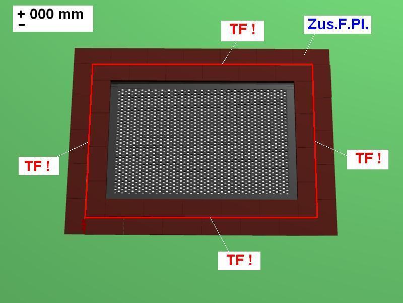
15 A.z.Ar. Excavate.1,40 m x 1,40 m = G O.K. PS Trampoline/Foundation frame (1,25 m x 1,25 m) Drainage layer Top-ground surface S: A - A View: A - A TF! WH-Bor! Zus.F.Pl. T.anh.! Lot! OK.- Tr. Lot! OK.- FER./SER. TAM Styrofoam Sand (Granulat) Required space including safety zone Parting line 1 cm around the Trampoline / (shown in orange in diagrams)!! Connect trampoline to foundation frame Provided upon request! Wet pour tiles placed around trampoline Lifting trampoline to install or clean! (1. Trampoline in natural ground surfacing) Installing: View A.z.Ar. When lifting or lowering the trampoline pay attention that it is equally lifted on all 4 outer corners! The Trampoline must be installed evenly onto the foundation. Cleaning: After excavating the area on the folding hinge side has been done, proceed as followed: Upper edge of Trampoline: Install equally level. Upper edge of foundation: Install equally level. Trampoline outer measurements Pay attention that the parting line/joint is kept clean! Place 1cm thick styrofoam in the area around the trampoline (max. height of the styrofoam is the lower edge of outer rubber surfacing on top of the trampoline!) (view diagram) Fill the parting line/joint with sand or granulate! (view diagram) T:\PLAY\Play Installation Instructions\Installation Instructions \20_02_ en-000.doc
16 5. Post Installation Checks If the equipment has not been installed safely, you must ensure that the public is prevented from using it. 5.1 Marking filler depth Labelling the posts to show the depth of material provided as fall protection (i.e. loose filler). 5.2 The equipment has not been installed safely in the following cases: Safe equipment installation is not complete. The protective surface has not been installed yet. Appropriate maintenance work cannot guarantee operational safety. 5.3 Removal of all assembly aids Please make sure that all assembly aids have been removed from the playing area. The equipment must not be approved for use until this check has been made. 5.4 Information about inspection of the equipment before it is used for the first time There are no special inspection requirements to be met before the equipment is used for the first time. 5.5 Retighten bolts After one week of play, please retighten all bolts again. Later upon respective maintenance T:\PLAY\Play Installation Instructions\Installation Instructions \20_02_ en-000.doc
17 B Maintenance Instructions Trampoline Piccolo Art T:\PLAY\Play Installation Instructions\Installation Instructions \20_02_ en-000.doc
18 Revisionshistorie Revision Maintenance instructions. Revision T:\PLAY\Play Installation Instructions\Installation Instructions \20_02_ en-000.doc
19 6. Introduction Maintenance 6.1 General Information This equipment should be installed, inspected, maintained and operated in accordance with EN guidelines. Please note: Providing any necessary repairs are carried out, a piece of play equipment that is inspected regularly cannot become so damaged that it is dangerous. Any spare parts which may be required can be obtained directly from your supplier. This equipment should only be assembled, maintained and repaired by persons with the necessary expertise. A copy of the inspection record should be given to the operator, who must confirm receipt. This maintenance instruction is based on the standard EN :2008. T:\PLAY\Play Installation Instructions\Installation Instructions \20_02_ en-000.doc
20 7. General Maintenance Information 7.1 Maintenance intervals Maintenance intervals are based on average use. Please note that more frequent inspections and/or maintenance are required if the play equipment is subject to intensive use. 7.2 Inspection frequency The frequency of inspections must be based on actual use. Factors that affect frequency include vandalism, location (e.g. coastal proximity), air pollution and the age of the equipment. 7.3 Maintenance products and procedures All nuts and bolts are hot-dip galvanised or stainless steel. One of the characteristics of stainless steel is that uncontrolled cold welding may occur when the nuts are tightened. To prevent this, it is necessary to spray the nuts and bolts with Teflon spray or another similar lubricant. 7.4 Spare parts All spare parts must conform to the manufacturer s specifications. 7.5 Identifying spare parts All spare parts are listed in the parts list. The parts list follows the installation requirements. 7.6 Special instructions for the disposal of individual equipment components No special instructions are necessary for the disposal of individual equipment components. 7.7 Special measures during the break-in period No later than 2 weeks after assembly, all screwed connections should be checked and tightened if necessary. 7.8 Drainage holes All drainage holes should be kept clear. 7.9 Maintenance of protective surfaces Surfaces providing fall protection must also be maintained regularly. It is particularly important to maintain the correct level of loose surface material and add more if necessary T:\PLAY\Play Installation Instructions\Installation Instructions \20_02_ en-000.doc
21 7.10 Faults Faults must be repaired as soon as they are detected. If serious defects that compromise safety cannot be repaired straight away, the public must be prevented from using the equipment with immediate effect Loose screws Loose screws always cause quality problems and put safety at risk. Therefore, loose screws should always be tightened and checks carried out to ensure that there are no missing screws (e.g. look out for holes you can see through) Preventing equipment use Use of the equipment should be prevented in the event of incomplete installation, disassembly, maintenance, repairs and faults Safeguarding the guarantee Steel posts and footings are guaranteed if regular maintenance is carried out and recorded in writing. Maintenance first takes place after 3 years. The steel posts must be excavated as far as the concrete foundations and checked for corrosion. Zinc paint should be applied to any corroded areas and scratches. Specific maintenance advice None T:\PLAY\Play Installation Instructions\Installation Instructions \20_02_ en-000.doc
22 8. Maintenance Timetable 8.1 Special Advices Maintenance interval We strongly advise you to carry out inspections and maintenance work within the specified periods as use of the equipment, the weather and malicious vandalism cause wear and tear that compromises the safety and function of the equipment Maintenance intervals in the event of intensive use Please note that more frequent inspections and/or maintenance are required if the play equipment is subject to intensive use Faults that compromise safety In the event of a fault that compromises safety, quick action must be taken. This may involve repairing it immediately or shutting down and dismantling the equipment Faults that compromise function Faults that compromise function should also be repaired immediately. Such faults lower the value of the equipment to the user and encourage malicious vandalism, which may render the equipment less safe. Any damage should also be repaired immediately T:\PLAY\Play Installation Instructions\Installation Instructions \20_02_ en-000.doc

23 9. Maintenance (Image) T:\PLAY\Play Installation Instructions\Installation Instructions \20_02_ en-000.doc
24 10. Monthly Maintenance Check the spaces between the equipment and the ground (clearance and height of fall). Check the ground surface in the area with fall protection for hard objects and loose foundations. Check all connecting elements and fittings for wear and tear and tighten if necessary. Replace damaged or missing parts. Check that moving metal parts (joints, springs, etc.) move smoothly and are not worn. Replace if necessary. It is not necessary to lubricate joints as we only use maintenance-free metal roller bearings. Check all attachments such as chains, ropes, nets, etc. for damage and replace if necessary. Check rubber parts, sleeves, etc. for wear and tear or damage and replace if necessary. If necessary, remove excess padding material from the post footings due to danger of rotting. Check the surface of wooden parts for damage caused by the weather or external influences and mould. Repair or replace if necessary. Check the surface of plastic and metal parts, e.g. slides, for damage and replace if necessary. 11 Quarterly maintenance Detailed inspection of the operation and stability of the equipment paying particular attention to any wear and tear. Tighten all forms of attachment. Repaint and retreat surfaces. Maintenance of fall protection surfaces. Lubrication of joints. Check the height of the fall and top up with loose filler if necessary. If the posts are labelled, top up as far as the mark. Retighten all bolts T:\PLAY\Play Installation Instructions\Installation Instructions \20_02_ en-000.doc
25 Annual Maintenance 12 Annual Maintenance Ascertaining that the equipment, foundations and surfaces are safe for operation. In particular, the equipment should be checked for decay and corrosion. It may be necessary to dig out or excavate certain components in order to do so. Zinc paint should be applied to corroded areas and scratches. Stability (check posts, bracing, foundations, etc.). Ascertaining whether there are any changes in equipment safety as a result of repairs that have been carried out or components that have been added or replaced.. The equipment must be inspected by someone with the necessary expertise in strict compliance with the instructions issued by the manufacturer. A copy of the inspection record should be given to the operator, who must confirm receipt. T:\PLAY\Play Installation Instructions\Installation Instructions \20_02_ en-000.doc
26
27 13 Maintenance Printout Name of Item: Trampoline Piccolo / Art-No Location: Customer or Operator: (Town, Council, School, etc) Date of inspection Inspector O.K. Accessible Barriered Defects Repaired by Date 35 T:\PLAY\Play Installation Instructions\Installation Instructions \20_02_ en-000.doc
28
29 14 Hand Over Document After the installation of the equipment pass the installation and maintenance documents to the operator. The operator has to receive the hand over documents. The complete filled and signed hand over document should be sent to the supplier. Art.-No.: Type of Item: Trampoline Piccolo Special Installation Frame Serial Number: Customer or Operator (Town, Council, School, etc.): Competent Person in Charge: Installation Company (Address): Responsible Assistant (Assembler): Received the complete assembly instructions, maintenance instructions and maintenance printout (Signature of Operator) (Signature of Installation Company) (Stamp) Date: T:\PLAY\Play Installation Instructions\Installation Instructions \20_02_ en-000.doc - 37
A Assembly Instructions for Trampoline 2000, Art With Installation Frame, Art
 A Assembly Instructions for Trampoline 2000, Art. 20.02.125 With Installation Frame, Art. 20.02.123 Or Special Installation Frame, Art. Nr. 20.02.128 Operator: Location: \\Fileserver\text\PLAY\Play Installation
A Assembly Instructions Trampoline 2012 Art
 A Assembly Instructions Trampoline 2012 Art. 20.02.108 Operator: Location: M:\Spogg\Englisch\20_02_108-01-en-001.doc\20-02-108-eng-01-001.doc - 1 - Revision history Revision 0 2012-03-21 Revision 1 2012-08-02
A Assembly Instructions Space Capsule, Art-No
 A Assembly Instructions Space Capsule, Art-No. 20.01.020 T:\PLAY\Play Installation Instructions\Installation Instructions 2012-2013\20_01_020-01-en-003.doc - 1 - Revision history Revision 0 2004-06-22
Assembly Instructions Maxi Cheops Pyramid Art B to set into concrete
 A Assembly Instructions Maxi Cheops Pyramid Art. 4643-3B to set into concrete \\Fileserver\text\PLAY\Play Installation Instructions\Installation Instructions 2012-2013\4643_3B-01-en-005.doc - 1 - Huck
Huck Seiltechnik GmbH Aßlar/Berghausen Germany
 A Assembly Instructions Dino 2, Rope Net Pyramid Art. 10.02.100 (Set into Concrete) T:\PLAY\Play Installation Instructions\Installation Instructions 2012-2013\10_02_100S-01-en-007.doc 3 Revision history
A Assembly instructions Mini Rope End Swinger Art. Nr
 A Assembly instructions Mini Rope End Swinger Art. Nr. 4585-45 Operator: Location: Attention! The distance between the center of the poles is 3.00 x 1.00m. In case of an eventual add-on of any other rope-parcours
Installation Instruction Sky Castle Art (Oak posts with steel safety lugs)
") Installation Instruction Sky Castle Art. 4638 (Oak posts with steel safety lugs) Revision history Revision 0 2004-10-04 The first allowed versio Assembly instruction Revision 3 2012-05-09 Befestigung der
Installation Instruction Sky Castle Art. 4638 (Oak posts with steel safety lugs) Revision history Revision 0 2004-10-04 The first allowed versio Assembly instruction Revision 3 2012-05-09 Befestigung der
A Assembly Instructions Liana Swing Art-No
 A Assembly Instructions Liana Swing Art-No. 20.01.090 Operator: Location: T:\PLAY\Play Installation Instructions\Installation Instructions 2012-2013\20_01_090-03-en-005 für Huck Nets mit bremsscheibe2
A Assembly Instructions Cheops-Pyramide Maxi Art.-Nr B With Anchor Plates
 HUCK Seiltechnik GmbH Dillerberg 3 35614 Asslar-Berghausen Seiltechnik A Assembly Instructions Cheops-Pyramide Maxi Art.-Nr. 4643-3B With Anchor Plates Betreiber: Standort: \\SOVE-FIL01\felles\Mont-anv-2010\33-100-100
Assembly instruction Cheops-Pyramid Midi. Art B to be dug in
 HUCK GmbH Dillerberg 3 35614 Asslar-Berghausen A Assembly instruction Cheops-Pyramid Midi Art. 4643-2B to be dug in Operator: Location: \\Fileserver\text\PLAY\Play Installation Instructions\Installation
A Instructions for the Assembly of Cheops-Pyramid Mini (EU-Gsm), Article, No B (embedded) Design: Steel Post
, Article, No B (embedded) Design: Steel Post") A Instructions for the Assembly of Cheops-Pyramid Mini (EU-Gsm), Article, No. 4643-1B (embedded) Design: Steel Post Operator: Location: Y:\Mont-anv-2010\33-100-000 støpefri forankr.doc 1 Revision history
A Instructions for the Assembly of Cheops-Pyramid Mini (EU-Gsm), Article, No. 4643-1B (embedded) Design: Steel Post Operator: Location: Y:\Mont-anv-2010\33-100-000 støpefri forankr.doc 1 Revision history
Playscape Classics Routine Inspection
 Playscape guidelines for playscape classics, including swings, slides, cableways, roundabouts, see saws, rockers, springies and climbers. Remove hazards, such as broken glass, litter, debris from trees
Instructions for Use Plain Trolley ULK Geared Trolley UHK
 Instructions for Use Plain Trolley Geared Trolley Item no. Load-carrying capacity (payload) Weight Trolley widths *special trolley widths* Device dimensions mm H / W / D Minimum curve radius mm -005 0,5
Northern Sales & Distribution Centre
 User Manual Industrial Door Northern Sales & Distribution Centre The Door Centre, Discovery Park, Crossley Road, Stockport, SK4 5BW /indupart /indupart /indupart /company/indupart-ltd Foreword This user
7. Protection System Testing
 MANUAL FOR INSTALLATION AND MONITORING OF UNDERGROUND STORAGE TANKS WITH FACTORY INSTALLED ANODES 1. SCOPE Manufactured by: Granby Industries 1020 André-Liné Granby, Québec, Canada, J2J 1J9. Telephone:
Instructions for Fitting, Operating and Maintenance Canopy Door RE / (St.: )
") EN Instructions for Fitting, Operating and Maintenance Canopy Door 1 818 012 RE / (St.: 12.2010) 12.2010 ENGLISH Contents 1 Safety Instructions... 3 1.1 Qualified persons... 3 1.2 Symbols and signal words
EN Instructions for Fitting, Operating and Maintenance Canopy Door 1 818 012 RE / (St.: 12.2010) 12.2010 ENGLISH Contents 1 Safety Instructions... 3 1.1 Qualified persons... 3 1.2 Symbols and signal words
Tool 3-2 Rope pump installation check list for quality control, 3 rd Edition August 2016 Rope Pump INSTALLATION checklist for quality control A A1 Des
 Rope Pump INSTALLATION checklist for quality control A A1 Site selection and preparations of the well before installation Hygiene and site selection Before the Rope pump is installed on a well, please
Installation, Operating and Maintenance Instructions Retractable Door / Art.-Nr.:
 Installation, Operating and Maintenance Instructions Retractable Door 06.2008 / Art.-Nr.: 1 818 024 ENGLISH CONTENTS PAGE 1 SAFETY REQUIREMENTS 3 1.1 Symbols and key words used 3 1.2 Designated use 3 1.3
Laboratory Series. Ultraviolet Ozone Destruct System Installation, Operation and Maintenance Manual. One Source for All Your UV Needs!
 Laboratory Series Ultraviolet Ozone Destruct System Installation, Operation and Maintenance Manual KEEP THIS MANUAL ON HAND IT IS IMPORTANT THAT THOSE RESPONSIBLE FOR THE INSTALLATION OF THIS EQUIPMENT,
MOBILE BELT GRINDER PASOVEC 75 RUNNER
 MOBILE BELT GRINDER PASOVEC 75 RUNNER Purchase order No. 1300 400 V / 60 Hz Purchase order No. 13001 480 V / 60 Hz Purchase order No. 13002 220 V / 60 Hz Operating manual CHANGE RESERVED 1 Contents: General
PE51 HURLEY 3 STATION METAL SWING SET OWNER'S MANUAL
 PE51 HURLEY 3 STATION METAL SWING SET OWNER'S MANUAL WARNING! The disassembled product may contain small parts which pose a choking hazard to children under 3. IMPORTANT: This product may contain sharp
PLAYSET MAINTENANCE PLAYSET CHECKLIST
 PLAYSET MAINTENANCE Cosmetic defects that do not affect the structural integrity of the product, or natural defects of wood such as warping, splitting, checking, twisting, shrinkage, swelling or any other
SAFETY DIRECTIVE 2.0 DEPARTMENTS AFFECTED
 SAFETY DIRECTIVE Title: Ladders Issuing Department: Town Manager s Safety Office Effective Date: July 1, 2014 Approved: Gilbert Davidson, Town Manager Type of Action: New 1.0 PURPOSE This procedure has
GEWAS 181 A. Alarm- and protection device Leak-water detector
 S07.0.1X.6C-04 Alarm- and protection device Leak-water detector Operating Manual GEWAS 181 A WEEE-Reg.-Nr. DE93889386 GHM Messtechnik GmbH Standort Greisinger Hans-Sachs-Str. 26 D-93128 Regenstauf +49
Before equipment use, please read this operation manual carefully. Serial Number: Date Purchased:
 Pushed & Geared Trolleys OPERATION MANUAL This operation manual is intended as an instruction manual for trained personnel who are in charge of installation, maintenance, repair etc. Before equipment use,
IMPORTANT INSTRUCTIONS FOR OPERATION & MAINTENANCE OF
 IMPORTANT INSTRUCTIONS FOR OPERATION & MAINTENANCE OF CONVEYORS EASIKIT 300 EASIKIT 450 EASIKIT 600, 900, 1200 & 1500 The manufacturer does not accept responsibility for any loss, damage to other equipment,
 DRUM BRAKE RIMS Periodic inspection of drum brake rims is necessary to determine indications of uneven or excessive wear. In general, brake rim failures other that regular wear are caused by brake linings
Operator s Manual. Go Galvanized! YOU'RE ALWAYS AHEAD...WITH A MODERN BEHIND.
 SUMMER 2008 rock & landscape rake Operator s Manual 003-7445 003-7450 003-7460 003-7440 003-7445 003-7450 YOU'RE ALWAYS AHEAD...WITH A MODERN BEHIND. P.O. Box 790 Beaumont, Tx 77704 409.833.2665 1.800.231.8198
Installation manual wall-mounted distributor
 EN Installation manual wall-mounted distributor EN 60003233 Issue 11.2016 2016-14-11 Table of contents 1 About this manual 3 1.1 Structure of the warnings 3 1.2 Symbols used 4 1.3 Signal words used 4 2
Operator s Manual. Go Galvanized! YOU'RE ALWAYS AHEAD...WITH A MODERN BEHIND.
 SUMMER 2008 C2 tilting grader blade Operator s Manual YOU'RE ALWAYS AHEAD...WITH A MODERN BEHIND. 003-5336 003-5342 003-5531 003-5544 P.O. Box 790 Beaumont, Tx 77704 409.833.2665 1.800.231.8198 Fax: 409.726.8333
PNEUMATIC SLIDING VALVE
 INSTALLATION, OPERATION, & #: MM-SV001 6-23-09 Rev. A Page 1 of 8 PNEUMATIC SLIDING VALVE PART NUMBERS (Including, but not inclusive) SV704MSTS, SV714MSTS, SV754MSTS, SV764MSTS, SV774MSTS, SV706MSTS, SV716MSTS,
Gym Dandy TEETER TOTTER TT-360. Model TT-360. Retain This Manual for Reference OWNER'S MANUAL
 NOTE: Please read all instructions carefully before using this product Table of Contents Safety Notice Gym Dandy TEETER TOTTER TT-360 Important Assembly Information Care and Maintenance Parts List Warranty
Assembly and Maintenance Manual Type AS
 Assembly and Maintenance Manual Type AS Hatschekstr.36 69126 Heidelberg Germany Tel +49(0)6221 30470 Fax +49(0)6221 304731 info@stieber.de www.stieber.de Date of issue: 30.05.2018 GB Revision: 0 U:\EngUsers\!ProduktDoku\1AAA_Einbauerklaerung_Wartungsanleitung_Konformitaetserklaerung\1AAA_Wartungsanleitungen\Orginal_Worddatei\_AS.docx
TITLE: Princetown Play Area Maintenance Procedure
 TITLE: Princetown Play Area Maintenance Procedure DOCUMENT MANAGEMENT This document constitutes Version 1; adopted on 10 March 2015. Introduction rents the Princetown Play area from the Duchy of Cornwall
INSTRUCTION MANUAL. A PEX S1 DAMPER Height Adjustable Coilover Damper Kit PRODUCT CODE - 268AM020
 INSTRUCTION MANUAL A PEX S1 DAMPER Height Adjustable Coilover Damper Kit PRODUCT CODE - 268AM020 (Table 1) Vehicle Application Application Vehicle Vehicle Model Engine Model Year MITSUBISHI LANCER EVOLUTION
DEMOUNTABLE BODY INSPECTION PROCEDURE Follow Detailed Instructions Inside for Each Step
 DEMOUNTABLE BODY INSPECTION PROCEDURE Follow Detailed Instructions Inside for Each Step Inspection Date: Inspected By: Serial #: Unit #: INSPECT: Inspected OK Needs Repair Comments Front Locking Bar Rear
Assembly and Maintenance Manual Type RSBW
 Assembly and Maintenance Manual Type RSBW Hatschekstr. 36 69126 Heidelberg Germany Tel +49(0)6221 30470 Tel +49(0)6221 304731 info@stieber.de www.stieber.de Stieber Clutch Date of issue: 16/03/2017 GB
Operator s Manual Portable Wood Chip Moisture Tester ENGLISH
 Operator s Manual Portable Wood Chip Moisture Tester ENGLISH DOCU-M0137 0212 Introduction THANK YOU for purchasing a Wood Chip Moisture Tester. READ THIS MANUAL carefully to learn how to operate and service
610 BUSHEL MANURE SPREADER
 610 BUSHEL MANURE SPREADER RODA MANUFACTURING 1008 LOCUST ST. HULL, IA. 51239 Art s-way Manufacturing 712-439-2366 Co., Inc. Hwy 9 West - PO Box 288 WWW.RODAMFG.COM Armstrong, IA. 50514 U.S.A 2 INTRODUCTION
RUBBER TRACK OPERATING MANUAL FOR AG TRACTORS
 RUBBER TRACK OPERATING MANUAL FOR AG TRACTORS EFFECTIVE: JULY 1, 2015 ABOUT THIS BOOK INTRODUCTION Firestone rubber tracks are designed and built for optimal performance and durability. In order to maximize
Mod: KLD6-12/35XLAS-N
 12/2011 Mod: KLD6-12/35XLAS-N Production code: 1914070 INSTRUCTION MANUAL LOGIC LINE PLUS HOOD Reseller Stamp for Warranty Dear customer, Above all, thank you for choosing our product and we would like
Assembly and Maintenance Manual Type ASNU
 Assembly and Maintenance Manual Type ASNU Hatschekstr.36 69126 Heidelberg Germany Tel +49(0)6221 30470 Fax +49(0)6221 304731 info@stieber.de www.stieber.de Date of issue: 30.05.2018 GB Revision: 0 U:\EngUsers\!ProduktDoku\1AAA_Einbauerklaerung_Wartungsanleitung_Konformitaetserklaerung\1AAA_Wartungsanleitungen\Orginal_Worddatei\_ASNU.docx
HERCULES II. Sportsplay Equipment, Inc., 5642 Natural Bridge, St. Louis, MO (314)
") Page 1 * IMPORTANT * PLEASE RETAIN THIS INSTRUCTION SHEET IN YOUR FILES. IT CONTAINS IMPORTANT REPLACEMENT PARTS INFORMATION. ALL EQUIPMENT SHOULD BE INSTALLED IN ACCORDANCE WITH THESE INSTRUCTIONS. IT
Page 1 * IMPORTANT * PLEASE RETAIN THIS INSTRUCTION SHEET IN YOUR FILES. IT CONTAINS IMPORTANT REPLACEMENT PARTS INFORMATION. ALL EQUIPMENT SHOULD BE INSTALLED IN ACCORDANCE WITH THESE INSTRUCTIONS. IT
Guideline for return of vehicles.
 Guideline for return of vehicles. Dear Customer, Thank you for choosing a vehicle from MAN. It is recommended that you inspect the vehicle thoroughly for damage before returning it. This brochure provides
Quick Reference. Sideguard Template. Installation Manual for Creating a Sideguard Template
 Quick Reference Sideguard Template Installation Manual for Creating a Sideguard Template Customer Satisfaction 1.0 Stealth Products strives for 100% customer satisfaction. Your complete satisfaction is
Toothed belt axis ELGC-TB-KF. Operating instruction [ ]
![Toothed belt axis ELGC-TB-KF. Operating instruction [ ]](/thumbs/83/87984161.jpg "Toothed belt axis ELGC-TB-KF. Operating instruction [ ]") Toothed belt axis ELGC-TB-KF en Operating instruction 8068220 2017-02 [8068222] Original instructions Identification of hazards and instructions on how to prevent them: Danger Immediate dangers which can
Toothed belt axis ELGC-TB-KF en Operating instruction 8068220 2017-02 [8068222] Original instructions Identification of hazards and instructions on how to prevent them: Danger Immediate dangers which can
A408 GB. Pneumatic oil and diesel pumps 1:1
 03 594 A408 GB Pneumatic oil and diesel pumps 1:1 G Operating instructions for Pneumatic oil and diesel pump 1:1 Contents 1. General details 2 1.1 Intended use 2 1.2 Design and functional description 2
Installation manual portable distributors
 EN Installation manual portable distributors EN 60003206 Issue 11.2016 15/11/2016 Table of contents 1 About this manual 3 1.1 Structure of the warnings 3 1.2 Symbols used 4 1.3 Signal words used 4 2 Intended
73000 Series Masoneilan* Sweep Angle Control Valves Models XX-73471
 GE Oil & Gas 73000 Series Masoneilan* Sweep Angle Control Valves Models XX-73471 Instruction Manual GE Data Classification: Public THESE INSTRUCTIONS PROVIDE THE CUSTOMER/OPERATOR WITH IMPORTANT PROJECT-SPECIFIC
Installation, Maintenance and Operation manual 4 Submersible sand fighter pump. Type: SSFP - Series
 Installation, Maintenance and Operation manual 4 Submersible sand fighter pump Type: SSFP - Series Prakash Pump Warranty We guarantee our products, for the period of 24 months from the date of purchase.
USER MANUAL PRODUCT CODE: WC CareCo (UK) Ltd, Hubert Road, Brentwood, Essex, CM14 4JE PAGE 1
 Ltd, Hubert Road, Brentwood, Essex, CM14 4JE PAGE 1") by USER MANUAL PRODUCT CODE: WC01059 CareCo (UK) Ltd, Hubert Road, Brentwood, Essex, CM14 4JE PAGE 1 CONTENTS 1. INTRODUCTION 2. IDENTIFICATION OF PARTS 3. SAFETY REGULATIONS 4. SAFETY WARNINGS 5. USER
by USER MANUAL PRODUCT CODE: WC01059 CareCo (UK) Ltd, Hubert Road, Brentwood, Essex, CM14 4JE PAGE 1 CONTENTS 1. INTRODUCTION 2. IDENTIFICATION OF PARTS 3. SAFETY REGULATIONS 4. SAFETY WARNINGS 5. USER
Safe use of portable ladders
 Safe use of portable ladders A portable ladder is primarily used for gaining access to areas above or below the ground, or other levels that are not provided with permanent access. The potential for injury
Quick Reference. Fixed ELITE Mounting Hardware. For Carbon Fiber Backs
 Quick Reference Fixed ELITE Mounting Hardware For Carbon Fiber Backs Customer Satisfaction 1.0 Stealth Products strives for 100% customer satisfaction. Your complete satisfaction is important. Please contact
Installation Manual SRR-70
 Installation Manual SRR-70 Contents 1. Symbols 3 2. General warnings 3 2.1 Safety requirements for assembly and first use 3 3. Terms and conditions 3 4. Area of application 3 5. Guidelines 4 6. Fixing
First Edition Part No
 First Edition Part No. 28433 Operating Instruction Manual First Edition Important Read, understand and obey these safety rules and operating instructions before operating this machine. Only trained and
BVM Corporation TYPE MS TONG 6,500 FT/LBS. TORQUE
 Page 1 BVM Corporation TYPE MS TONG 6,500 FT/LBS. TORQUE Part number: Serial Number: BVM CORPORTION TYPE MS TONG 6,500 FT/LBS. TORQUE WRNING: Manual tongs which have experienced excessive wear or are found
INSTALLATION GUIDELINES
 SUMP TANKS INSTALLATION GUIDELINES Thank you for purchasing a quality SumpTank. In order to gain the maximum benefit from your purchase, we have outlined the following instructions for the installation
LX1 Inspection Manual for Model LX1B. Table of contents 1. INSPECTION CLASSIFICATION DAILY INSPECTION FREQUENT INSPECTION...
 KTI KITO Technical Information LX1 Inspection Manual for Model LX1B LX1-1.1.1 1 / 9 Edition: C 03.06 Table of contents 1. INSPECTION CLASSIFICATION...2 2. DAILY INSPECTION...3 3. FREQUENT INSPECTION...3
Tidy Sheds are Imported from the UK
 South Africa s No.1 Storage Solution Nationwide Delivery 083 417 7190 info@tidysheds.co.za info@tidysheds.co.za Valid Until 31st October Largest Range of Sheds in South Africa Tidy Sheds are Imported from
Mini amateur football ground goals, street hockey goals, mobile, fully welded
 Fully welded Mini amateur football ground goals, street hockey goals, mobile, fully welded GS-APPROVED Completely made of aluminium Extremely robust and low risk of injury Goal frame square profile 80
FPU SYSTEMS OPERATION MANUAL (INCLUDING REPAIR PARTS & SPECIAL TOOL LIST) BOH CONTAINERIZED LATRINES BOH FPU Field Pack-up Units
 BOH CONTAINERIZED LATRINES BOH FPU Field Pack-up Units") FPU SYSTEMS OPERATION MANUAL (INCLUDING REPAIR PARTS & SPECIAL TOOL LIST) BOH CONTAINERIZED LATRINES BOH FPU Field Pack-up Units CHAPTER 4 OPERATOR MAINTENANCE INSTRUCTIONS 2016 BOH Environmental LLC This
FPU SYSTEMS OPERATION MANUAL (INCLUDING REPAIR PARTS & SPECIAL TOOL LIST) BOH CONTAINERIZED LATRINES BOH FPU Field Pack-up Units CHAPTER 4 OPERATOR MAINTENANCE INSTRUCTIONS 2016 BOH Environmental LLC This
SYDNEY TRAMWAY MUSEUM TROLLEY WIRE INSPECTION PROCEDURE
 TROLLEY WIRE INSPECTION PROCEDURE JUNE 2014 1. Document Details: Name: SYDNEY TRAMWAY MUSEUM Document Control Record Number STM 6029 Version Number: 15 TrolleyWire Inspection Procedure Document Status:
Important. Contents. Contact us:
 Operator's Manual First Edition Ninth Printing Important Read, understand and obey these safety rules and operating instructions before operating this machine. Only trained and authorized personnel shall
RE761 Lounger Tree Seat
 RE761 Lounger Tree Seat Maximum Field Rating - 300 lbs. Tree Diameter Range - 8" to 20" WARNING FOR GROUND LEVEL USE ONLY! Get parts online at www.huntriversedge.com P/N: OMRE76109 REV2: 03/02/15 2015
SERIES PC INSTRUCTION AND OPERATION MANUAL
 MEGGA SERIES PC INSTRUCTION AND OPERATION MANUAL Models PCT and PCF Close-coupled and frame-mounted single-stage horizontal end-suction pumps. WARNING: Read this manual before installing or operating this
PLAY AREA SAFETY INSPECTION REPORT
 PLAY AREA SAFETY INSPECTION REPORT Char Valley Parish Council October 2016 Park Name: Whitchurch Canonicorum Location: Village Hall Lower St. DT6 6RF This report is an independent safety assessment of
Spindle axis ELGC-BS-KF. Operating instructions [ ]
![Spindle axis ELGC-BS-KF. Operating instructions [ ]](/thumbs/87/97202885.jpg "Spindle axis ELGC-BS-KF. Operating instructions [ ]") Spindle axis ELGC-BS-KF en Operating instructions 8067243 2017-01 [8067245] Original instructions Identification of hazards and instructions on how to prevent them: Danger Immediate dangers which can lead
Spindle axis ELGC-BS-KF en Operating instructions 8067243 2017-01 [8067245] Original instructions Identification of hazards and instructions on how to prevent them: Danger Immediate dangers which can lead
Data Sheet WÖHR PARKING PLATFORM 501
 Data Sheet WÖHR PARKING PLATFORM 501 For lateral shunting. Suitable for condominium and office buildings. Dimensions in cm. Load per parking place max. 2000 kg (max. wheel load 500 kg). 500 500 90 *safety
INSTRUCTION MANUAL A PEX N1 DAMPER. Height Adjustable Coil Over Damper Kit PRODUCT CODE 269AM020. Vehicle Application
 INSTRUCTION MANUAL A PEX N1 DAMPER Height Adjustable Coil Over Damper Kit PRODUCT CODE 269AM020 (Table1) Vehicle Application Application Vehicle Vehicle Model Engine Model Year MITSUBISHI CT9A 4G63 03-
Unique 7000 Series Valve - Standard and Reverse Acting
 Instruction Manual Unique 7000 Series Valve - Standard and Reverse Acting ESE00213-ENUS4 2012-01 Original manual Table of contents The information herein is correct at the time of issue but may be subject
LK Shunt Cabinet VS2, Shunt Cabinet VS2 Prefab
 LK Shunt Cabinet VS2, Shunt Cabinet VS2 Prefab Design LK Shunt Cabinet VS2 The LK Shunt Cabinet VS2 is designed to be used when you wish to hide the LK Manifold RF and LK Manifold Shunt VS2. The cabinet
Important. Contents. Contact us:
 Operator's Manual Third Edition Third Printing Important Read, understand and obey these safety rules and operating instructions before operating this machine. Only trained and authorized personnel shall
AIR-SUSPENSION. Designed for: Alko Chassis
 AIR-SUSPENSION Dunlop Systems and Components Het Wegdam 22 7496 CA Hengevelde The Netherlands Tel.: +31-(0)547-333065 Fax: +31-(0)547-333068 Website: www.dunlopsystems.com Art. nr.: L.AL.02 Designed for:
HST -LS Interlocking device (Translation of Original Manual)
") Installation and Operating Manual for Components HST -LS Interlocking device (Translation of Original Manual) HST-LS Ident.-No.: 10268 HST-LS Ident.-No.: 10269 HST-LS, pictured Ident-Nr. 10269 The image
Installation and Operating Manual for Components HST -LS Interlocking device (Translation of Original Manual) HST-LS Ident.-No.: 10268 HST-LS Ident.-No.: 10269 HST-LS, pictured Ident-Nr. 10269 The image
Tidy Sheds are Imported from the UK
 South Africa s No.1 Storage Solution Nationwide Delivery 083 417 7190 info@tidysheds.co.za Largest Range of Sheds in South Africa Tidy Sheds are Imported from the UK Tidy Sheds are Hot Dipped Galvanized
Exchange of rollers from the XTS-Mover
 Service documentation for AT901-0050-0550 and AT9011-00x0-0550 Version: Date: 1.0 0.10.017 Table of contents Table of contents 1 Foreword... 5 1.1 Notes on the documentation... 5 1. Documentation issue
Directions for use VIBRO FLEX 7400
 Directions for use VIBRO FLEX 7400 Contents Introduction... 3 Identification... 3 Explanation of symbols... 4 Safety... 5 General safety advice... 5 Coupling and uncoupling... 5 Three-point hitch or linkage...
OMEGA. Separator Units. Standen Engineering Limited. Hereward Works, Station Road, Ely, Cambridgeshire. CB7 4BP England.
 OMEGA Separator Units Standen Engineering Limited. Hereward Works, Station Road, Ely, Cambridgeshire. CB7 4BP England. Tel: 01353 661111 www.standen.co.uk Fax: 01353 662370 IMPORTANT This operator s handbook
3.25 Ton Heavy Duty Floor Jack
 Please dispose of packaging for the product in a responsible manner. It is suitable for recycling. Help to protect the environment, take the packaging to the local amenity tip and place into the appropriate
SEBA HYDROMETRIE, User Manual KLL
 SEBA HYDROMETRIE Tel. (+49) 8341 / 9648-0 Produkt Nr.: KLL GmbH & Co. KG, Germany Fax (+49) 8341 / 964848 Revision: 1.0 Gewerbestr. 61a E-Mail: info@seba.de letzte D-87600 Kaufbeuren Internet: www.seba.de
Operating Instructions
 Page 1 of 11 CONTENTS 1 PURPOSE... 3 2 APPLICATION... 3 3 DESCRIPTION... 3 4 FUNCTION... 5 5 TECHNICAL PARAMETERS... 5 6 TYPE IDENTIFICATION KEY MMP... 6 7 DIMENSIONAL DRAWING... 7 8 HYDRAULIC DIAGRAM...
Starting up hydraulic systems
 General / Installation A hydraulic system that operates economically, safely, and trouble-free requires careful planning, as well as proper installation and start-up. Conscientious maintenance has a considerable
INSTRUCTIONS FOR USE BALL PICKER
 ENGLISH http://www.rangeservant.com INSTRUCTIONS FOR USE BALL PICKER Contents 1 General information 4 1.1 Foreword 4 1.2 Manufacturer's declaration 5 1.3 Fel! Bokmärket är inte definierat. 1.3.1 Ball Picker
Gym Dandy TEETER TOTTER TT-320. Model TT-320. Retain This Manual for Reference OWNER'S MANUAL
 NOTE: Please read all instructions carefully before using this product Gym Dandy Table of Contents Safety Notice Hardware Pack TEETER TOTTER TT-320 Assembly Instruction Parts List Operation Tips Warranty
AGRO. Manual Bucket elevator T53/T54/T55 Version
 AGRO Manual Bucket elevator T53/T54/T55 Version 70505.1 Contents Contents...2 Introduction...4 EU Declaration of conformity...5 Conditions for use...6 General information...7 Delivery...7 Storage...7 Noise
Overhead transmission lines Spacers
 = SVENSKA KRAFTNÄT SWEDISH NATIONAL GRID UNIT, BUSINESS AREA AEL, Asset Management Lines OUR REFERENCE TR05-08E DATE 2016-06-09 CONSU12TATIONS TECHNICAL GUIDELINE REVISION 3 APPROVED Overhead transmission
2 TONNE TROLLEY JACK
 2 TONNE TROLLEY JACK 61829 IMPORTANT: Please read these instructions carefully to ensure the safe and effective use of this product and save these instructions for future reference. This manual has been
Tension Meter. Edition FT 03.E. FT Series. Instruction Manual. Valid as of: Please keep the manual for future reference!
 Tension Meter FT Series S C H M I D T c o n t r o l i n s t r u m e n t s Edition FT 03.E Model FT Instruction Manual Valid as of: 01.09.2011 Please keep the manual for future reference! Contents 1 Warranty
ROTARY TILLER TYPE "URT"
 Del Morino srl, v.caroni di Sotto 19, I-52033 Caprese Michelangelo AR Italy Ph: +39-575-791059 Fax: +39-575-791210 E.mail: export@del-morino.it http://www.del-morino.it USE AND MAINTENANCE MANUAL ROTARY
Trailer Assembly Guide Model MMT5X GVWR All Steel Trailer
 DETAIL K2 INC. 1080 Clay Ave., Unit #2 Burlington Ont. L7L 0A1 1-888-277-6960 Trailer Assembly Guide Model MMT5X7 2050 GVWR All Steel Trailer 7.5 ft. (229 cm) Utility Trailer MMT5X7 man v.160328 STEP 1
For sowing broad acres of turf, there are machines which are of value but should still be used in conjunction with manual seeding.
 Seeders For sowing broad acres of turf, there are machines which are of value but should still be used in conjunction with manual seeding. Hydraulic Pruners Chainsaws and secateurs on extension arms are
General Operating Manual
 This Operating Manual is valid for the following hydraulic components of MOTRAC-Hydraulik GmbH: IMA V-Manifold-Blocks Blocks IMA V-Mounting-Units Units Valves and Housings IMA V-Sandwich plates IMA V-Mounting-plates
EasySelect-Cup Manual Powder Gun
 E Operating Instructions and Spare parts list EasySelect-Cup Manual Powder Gun EasySelect-Cup 27 28 EasySelect-Cup Table of Contents Safety rules EasySelect-Cup Manual Powder gun...........................................
3 TONNE TROLLEY JACK
 3 TONNE TROLLEY JACK 16407 These instructions accompanying the product are the original instructions. This document is part of the product, keep it for the life of the product passing it on to any subsequent
Matrix - Glass Coffee Table
 Matrix - Glass Coffee Table Assembly Instructions - Please keep for future reference 60/867 609/0708 Dimensions Width - 00cm Depth - 0cm Height - cm Important - Please read these instruction fully before
Matrix - Glass Coffee Table
 Matrix - Glass Coffee Table Assembly Instructions - Please keep for future reference 0/87 09/0708 Dimensions Width - 00cm Depth - 0cm Height - cm Important - Please read these instruction fully before
Pneumatic actuator Assembly & maintenance procedures
 Pneumatic actuator Assembly & maintenance procedures SPRING RETURN ACTUATOR Fig.7901 DOUBLE ACTING ACTUATOR Fig.7902 - LCIE 05 AR 022 2 CONTENTS 1. Applicable Range... page 4-6 2. General Information...
BERYL SLIDE AND SWING OWNER'S MANUAL
 BERYL SLIDE AND SWING OWNER'S MANUAL WARNING! The disassembled product may contain small parts which pose a choking hazard to children under 3. IMPORTANT: The owner s manual contains safety, assembly,
Adjustable Speaker Mount GRAVIS 8
 Adjustable Speaker Mount GRAVIS 8 User's Manual Translation of the original instructions Important Information, Please Read Before Use! KLING & FREITAG GmbH Junkersstraße 14 D-30179 Hannover TEL +49 (0)
Adjustable Speaker Mount GRAVIS 12
 Adjustable Speaker Mount GRAVIS 12 User's Manual Translation of the original instructions Version 3.3 Released: 19.01.2017 Important Information, Please Read Before Use! KLING & FREITAG GmbH Junkersstraße