KJLC-RV VACUUM PUMP OPERATION MANUAL
|
|
|
- Regina York
- 5 years ago
- Views:
Transcription


1 VACUUM PUMP OPERATION MANUAL
2 CORPORATE HEADQUARTERS Kurt J. Lesker Company 1925 Route 51 Jefferson Hills, PA USA Phone: Fax: EUROPEAN HEADQUARTERS Kurt J. Lesker Company, Ltd Burgess Road Hastings, East Sussex TN35 4NR, England Phone: Fax: CONTACT US California, USA Canada Hungary Germany ASIAN HEADQUARTERS Kurt J. Lesker Shanghai Trading Co. Building 63, Lane 1000 Zhangheng Road Pudong New Area, Shanghai P.R. China Phone: Fax:
3 CONTENTS QUALITY... 1 DECLARATION OF CONFORMITY (MACHINERY)... 1 DECLARATION OF CONFORMITY (ELECTROMAGNETIC COMPATIBILITY)... 2 WARRANTY... 3 DOCUMENT CONTROL... 4 INTRODUCTION... 5 SAFETY... 5 SAFETY SYMBOLS... 5 DESCRIPTION... 6 OPERATING PRINCIPLE... 7 GAS BALLAST... 7 PUMPING APPLICATIONS... 8 GETTING STARTED... 9 TRANSPORTATION... 9 INSPECTION... 9 SUPPLIED EQUIPMENT... 9 INSTALLATION LOCATION OIL VACUUM SYSTEM CONNECTION ELECTRICAL INSTALLATION OPERATION PRIOR TO OPERATION INITIAL WARMUP AND BEST PRESSURE PUMPING NON-CONDENSABLE GAS PUMPING CONDENSABLE GAS PUMPING MAINTENANCE PREVENTATIVE MAINTENANCE TROUBLESHOOTING SERVICE AND SPARE PARTS SERVICE SPARE PARTS STANDARD REPAIR KITS ACCESSORIES DATA TECHNICAL DATA KURT J. LESKER COMPANY I
4 ELECTRICAL DATA PUMP DIMENSIONS SHUTDOWN/STORAGE/DISPOSAL SHUTDOWN NORMAL CONDITIONS PUMPING CONDENSABLE VAPORS STORAGE STORAGE PROCEDURE DISPOSAL COMPANY INFORMATION QUALITY POLICY ABOUT US FOUR FOCUSED DIVISIONS ILLUSTRATIONS FIGURE 1: KJLC-RV PUMP SERIES (KJLC-RV 206, 212, 224, AND 236)...6 FIGURE 2: GAS BALLAST...7 FIGURE 3: KJLC-RV PUMP FIGURE 4: OIL GAUGE FIGURE 5: IEC CONNECTOR AND ON/OFF SWITCH FIGURE 6: DIAGRAM OF PUMP PARTS FIGURE 7: PUMP DIMENSIONS TABLES TABLE 1: MAXIMUM OIL CAPACITY TABLE 2: MAINTENANCE SCHEDULE TABLE 3: KJLC-RV STANDARD REPAIR KIT TABLE 4: RECOMMENDED ACCESSORIES TABLE 5: TECHNICAL DATA TABLE 6: ELECTRICAL DATA TABLE 7: EXTERIOR DIMENSIONS KURT J. LESKER COMPANY II

5 QUALITY QUALITY DECLARATION OF CONFORMITY (MACHINERY) Kurt J. Lesker Company Burgess Road Hastings, East Sussex TN35 4NR hereby declare that for the range of machinery identified as: KJLC-RV206 Vacuum Pumps KJLC-RV212 Vacuum Pumps KJLC-RV224 Vacuum Pumps Serial Numbers: thru and thru conforms with the requirements in accordance with the following European Directive: Directive 2006/42/EC of May 2006 relating to Machinery the following Type C Harmonised Standards, and normative references were complied with: EN1012-2:1996+A1:2009 Compressors and vacuum pumps Safety requirements Part 2: Vacuum pumps EN :2006/AC: 2010 Safety of machinery Electrical equipment of machines Part 1: General requirements Technical documentation is compiled in accordance with Annex VII (B) of the Directive. Technical File Number: MSTFPN We undertake to transmit, in response to a reasoned request by the appropriate national authorities, relevant information on the completed machinery identified above. The method of transmission shall be electronic in the form of a PDF document or documents. Machinery identified above is in conformance with the following additional, applicable directives: Directive 2004/108/EC of December 2004 relating to Electromagnetic Compatibility Signed by: Date: September 1, 2014 Adam Bartlett Managing Director Kurt J. Lesker Company Ltd, Burgess Road, Hastings East Sussex TN35 4NR, UK Signed by: Date: September 1, 2014 Brian Rist Product Safety and Compliance Kurt J. Lesker Company, 1925 Route 51, Jefferson Hills, PA 15025, USA The technical documentation for the machinery is available from the above referenced address. KURT J. LESKER COMPANY 1
6 DECLARATION OF CONFORMITY (ELECTROMAGNETIC COMPATIBILITY) hereby declare that for the machinery identified as: Kurt J. Lesker Company Burgess Road Hastings, East Sussex TN35 4NR KJLC-RV206 Vacuum Pumps KJLC-RV212 Vacuum Pumps KJLC-RV224 Vacuum Pumps Serial Numbers: thru and thru conforms with the requirements in accordance with the following European Directive: Directive 2004/108/EC of December 2004 relating to Electromagnetic Compatibility Technical documentation is compiled in accordance with Article 7 & Annex II of the Directive. The Technical File provides evidence of the conformity of the apparatus with the essential requirements of the Directive Technical File Number: EMCTFPN We undertake to transmit, in response to a reasoned request by the appropriate national authorities, relevant information on the completed equipment identified above. The method of transmission shall be electronic in the form of a PDF document or documents. Equipment identified above is in conformance with the following additional directives: Directive 2006/42/EC of May 2006 relating to Machinery Signed by: Date: September 1, 2014 Adam Bartlett Managing Director Kurt J. Lesker Company Ltd, Burgess Road, Hastings East Sussex TN35 4NR, UK Signed by: Date: September 1, 2014 Brian Rist Product Safety and Compliance Kurt J. Lesker Company, 1925 Route 51, Jefferson Hills, PA 15025, USA The technical documentation for the machinery is available from the above referenced address. KURT J. LESKER COMPANY 2
7 WARRANTY EQUIPMENT WARRANTY AND REMEDY: COMPANY warrants that the Equipment fabricated and furnished by COMPANY hereunder shall be free from material defects in workmanship and materials. If any of the Equipment fabricated and furnished by COMPANY materially fails to conform to the warranty set forth in the preceding sentence, CUSTOMER's remedy shall be limited, at COMPANY's option, to either (i) repair or replacement of the non-conforming Equipment, F.O.B. point of repair or replacement, with shipping charges prepaid by CUSTOMER; or (ii) repayment of the portion of the contract price paid by CUSTOMER attributable to such non-conforming Equipment. Dismantling and reinstalling work is excluded from this Equipment Warranty and Remedy. SERVICES WARRANTY AND REMEDY: COMPANY warrants that any services furnished under COMPANY's proposal or quotation will conform to standards of practice generally accepted in the profession and/or industry for services of a similar nature. If the services provided by COMPANY materially fail to conform to the warranty set forth in the preceding sentence, CUSTOMER's remedy shall be limited to revision, replacement or reperformance, at COMPANY's expense, of those services which COMPANY reasonably determines fails to so conform. WARRANTY PERIOD: The warranties set forth in section above shall be effective for a period of twelve (12) months from the date of shipment of the Equipment from COMPANY's plant. The warranty set forth in section 2 above shall be effective for a period ending twelve (12) months from the date of performance of the services. WARRANTY CONDITIONS AND LIMITATIONS: CUSTOMER's right to enforce the foregoing warranties is expressly conditioned upon CUSTOMER notifying COMPANY in writing during the Warranty Period of any alleged non-conformity or defect, stating specifically the nature of the alleged non-conformity or defect. COMPANY shall have the right, upon such notification, to review, inspect and/or examine the Equipment indicated by CUSTOMER, and CUSTOMER shall make the Equipment available to COMPANY for such purposes. The foregoing warranties shall not apply if COMPANY's review, inspection or examination discloses that the Equipment (i) has not been installed, maintained or operated in accordance with COMPANY's instructions; (ii) has been used by CUSTOMER in a manner or for applications not recommended by COMPANY; (iii) has been repaired, altered or modified by CUSTOMER; (iv) has been subjected to other than normal use, storage, handling, installation, operation or maintenance; or (v) has been damaged by fire, act of God, any cause covered by CUSTOMER's insurance or any other event or occurrence not caused by COMPANY. The foregoing warranties shall not apply to Equipment, or parts or components thereof, which are not manufactured or processed by COMPANY, or which are purchased by COMPANY from another party or partied. The manufacturer's warranty for such Equipment, parts or components, if any, shall be assigned to CUSTOMER without recourse to COMPANY. The foregoing warranties shall not apply to designs, materials or specifications furnished or specified by CUSTOMER and incorporated into the Equipment. THE EXPRESS WARRANTIES AND REMEDIES SET FORTH IN THIS SECTION ARE EXCLUSIVE AND ARE CONDITIONED UPON TIMELY NOTIFICATION BY CUSTOMER. THEY ARE GIVEN BY COMPANY AND ACCEPTED BY CUSTOMER IN LIEU OF ANY AND ALL OTHER REMEDIES, WARRANTIES, AND GUARANTEES, EXTOUCHED OR IMPLIED, AND IN LIEU OF ANY IMPLIED WARRANTIES OF MERCHANTABILITY AND FITNESS FOR A PARTICULAR PURPOSE, ALL OF WHICH ARE HEREBY SPECIFICALLY EXCLUDED AND DISCLAIMED. COMPANY neither assumes, nor authorizes any representative or other person to assume for it, any obligation or liability other than such as is expressly set forth in this section. Any change, modification, extension or addition to the foregoing warranties, remedies or limitations shall not be binding upon COMPANY unless in writing and duly executed by an authorized officer of COMPANY. KURT J. LESKER COMPANY 3
8 DOCUMENT CONTROL Version Date Released Change Notice Remarks N/A Draft first release Content and format Final draft for review Final copy Final copy for customer use This manual contains drawings and technical instructions that are proprietary by the Kurt J. Lesker Company. These items are not to be reproduced, published or distributed to a third party without written consent from the Kurt J. Lesker Company. The Kurt J. Lesker Company assumes no liability for damages to customer facilities or personnel resulting from misuse or misapplication of the unit. All information, illustrations, and specifications in this manual are based on the latest product information available at the time of printing. KJLC reserves the right to make changes at any time without notice. Any duplication of this manual, in whole or in part, without express written approval from Kurt J. Lesker Company is strictly prohibited. KJLC assumes no responsibility for equipment additions or modifications without KJLC s written consent. Component repair or replacement done by the user during the warranty period without direction or approval from KJLC Global Service can void the equipment manufacturer s warranty. Original instructions are written in English. KURT J. LESKER COMPANY 4


 and the International Organization for Standardization (ISO) safety symbols that")
9 INTRODUCTION INTRODUCTION SAFETY Please read all safety notes provided by KJLC with caution. The pump must only be operated and maintained by trained staff as described in this operation manual. Should you have any issues relating to safety, operation, or maintenance of the pump, please contact Kurt J. Lesker Company. SAFETY SYMBOLS The following safety notations will be used throughout this manual: WARNING Warnings are used when failure to observe the instruction could result in injury or death. CAUTION Cautions are used when failure to observe the instruction could result in damage to the equipment, associated equipment, and process. NOTE: Notes are given to highlight any technical requirements, operations, procedures, or conditions that should be emphasized. The following are American National Standards Institute (ANSI) and the International Organization for Standardization (ISO) safety symbols that may be used within this manual or located on the pump: GENERAL WARNING EXPLOSIVE HOT SURFACE PINCH POINT ELECTRIC HAZARD LIFTING HAZARD FACE/ BREATHING HAZARD GLOVES REQUIRED TWO PERSON LIFT READ OPERATOR S MANUAL KURT J. LESKER COMPANY 5


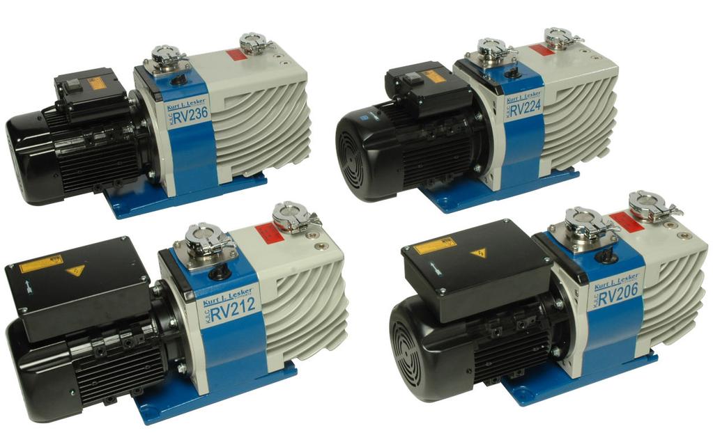
10 DESCRIPTION The KJLC-RV pumps are two stage oil sealed rotary vane pumps. The pumps are driven by a motor that is directly coupled through a flexible coupling to the pump shaft. The motor is cooled by a fan which guides air along the motor fins. The pumps are cooled by an additional fan attached to the motor coupling. The pump has KF25 inlet and outlet ports and a gas ballast valve for pumping of condensable gases. When the pump is turned off, an anti-suckback valve seals the inlet of the pump and prevents the back flow of air and oil into the vacuum system. The oil gauge and nameplate are positioned on the front of the oil casing. The oil gauge is used for monitoring the oil level and condition. Two oil intake plugs and an oil drain plug are located on the oil casing. The pump is mounted on a base plate to which four rubber feet can be installed as vibration isolators or it can be anchored to desired location. FIGURE 1: KJLC-RV PUMP SERIES (KJLC-RV 206, 212, 224, AND 236) KURT J. LESKER COMPANY 6

11 OPERATING PRINCIPLE Rotary vane pumps use an eccentrically mounted rotor inside the pump housing. Two vanes sliding in the rotor are forced against the housing by centrifugal force. As a vane passes in front of the inlet, an increasing volume is formed in which the gas from the chamber enters. When the second vane passes the inlet, this volume is then closed. The gas trapped in this volume between the two vanes is swept towards the exhaust as the rotor rotates. Gas is then compressed until expelled through the exhaust valve. Any liquid oil that may be in the gas is trapped by an internal oil filter. The gas exits the pump through the outlet port. GAS BALLAST The gas ballast is provided to help prevent the condensation of vapors in the pump. It is used to change the amount of air introduced into the low vacuum stage of the pump. The gas ballast valve has two positions to choose from: 1. Closed gas ballast (Position C ). Position used for: Reaching best possible pressure Pumping non-condensable gases 2. Open gas ballast (Position 'II'). Position used for: Pumping of condensable vapors Decontaminating the pump oil When using an open gas ballast, the pump will operate with increased noise level, increased temperature level, and oil loss at outlet of the pump. For this position, we recommend the use of an exhaust oil mist eliminator (see Table 4 for recommended mist eliminator). FIGURE 2: GAS BALLAST KURT J. LESKER COMPANY 7
12 PUMPING APPLICATIONS KJLC-RV pumps are general vacuum pumps intended for use in many vacuum applications. Common applications are chamber roughing, turbo pump and diffusion pump backing, and cryo pump regeneration. KJLC-RV pumps are NOT suited for: Dust removal Pumping liquids Gases which are corrosive or reactive Gases with oxygen concentration greater than what is in atmosphere (>21%) Explosive gases Hazardous gases Pyrophoric gases WARNING The KJLC-RV pumps are NOT ATEX compliant and not intended for use in positive pressure applications. Maximum inlet pressure is 1 ATM (760 Torr/1013 mbar). Never use the pump for unapproved applications. KURT J. LESKER COMPANY 8

13 GETTING STARTED GETTING STARTED TRANSPORTATION When you receive the pump, unpack it carefully. For best access to a boxed pump, remove the upper foam insert and cut the box around the pump to gain access to the lifting points. Lifting points are under the motor and under the pump oil casing. WARNING Improper handling of the pump could result in injury and/or equipment damage. INSPECTION Upon receipt of the pump, ensure: 1. The product is consistent with what you ordered. 2. No damage occurred during transport. If product does not pass inspection, please contact KJLC. SUPPLIED EQUIPMENT The following equipment is supplied with the KJLC-RV pumps: Pump with motor 2 x quarts of KJLSS19 pump oil 1 x KF25 centering ring with mesh trap (Inlet) 1 x KF25 centering ring (Outlet) 2 x KF25 clamping rings 2 x KF25 blanking flanges WARNING The KF25 blanking flanges are supplied for shipment only. These flanges must be removed prior to operation. KURT J. LESKER COMPANY 9
14 INSTALLATION Proper installation requires selection of a suitable location, filling the pump with oil, and making appropriate vacuum and electrical connections. LOCATION Select an appropriate location for the KJLC-RV pump. 1. Pumps should be installed on a level, flat, horizontal surface (maximum tilt angle is 10 degrees from horizontal). The pump is intended for indoor use only. 2. When installing the pump consider convenience for connection, operation, and wiring. 3. The chosen location should allow for sufficient air circulation to cool the pump. Keep front and rear of pump unobstructed. 4. Location should also consider the need to protect any electrical circuits from dripping water resulting from condensation on cold surfaces (examples of hazards could be water cooled devices, cryo pumps during regeneration, etc.). 5. Locate the pump so that the oil gauge is visible. 6. Locate the pump so the oil intake and drain plugs are easily accessible. 7. Use the rubber feet supplied with pump as vibration absorbers or use anchor holes on base plate for anchoring to selected location. 8. The pump operating ambient temperature is 50 F (10 C) to 104 F (40 C). KURT J. LESKER COMPANY 10
15 OIL KJLSS19 oil is the recommended fluid for use with KJLC-RV pumps. Use of any other fluid in the pump may impact performance and void warranty. CAUTION The KJLC-RV pumps do not contain oil during shipping. KJLSS19 oil is supplied in separate bottles within the pump box. The pump must be filled with oil before usage. OIL FILL PROCEDURE 1. Remove one of the oil intake plugs (see Figure 3 for location). 2. Pour oil into the pump until the oil level just reaches the MAX mark on the oil gauge sight glass (Figure 4). If the oil level goes above the MAX mark, remove the drain plug and drain the excess oil from the pump. Table 1 contains maximum oil capacity values for each pump model. 3. Replace the oil intake plug. Tighten the plug firmly, but do not over tighten. 4. After starting the pump for operation, recheck oil level in oil gauge sight glass to ensure adequate oil level. FIGURE 3: KJLC-RV PUMP PUMP MODEL OIL CAPACITY (L / QT) KJLC-RV / 1.4 KJLC-RV / 1.2 KJLC-RV / 1.5 KJLC-RV / 1.9 FIGURE 4: OIL GAUGE TABLE 1: MAXIMUM OIL CAPACITY KURT J. LESKER COMPANY 11
16 VACUUM SYSTEM CONNECTION Prior to operation, the pump must have appropriate vacuum system connections. WARNING Remove the blanking flanges prior to vacuum system connection. 1. Connect the inlet and outlet lines with a centering ring and a clamping ring each. Use the centering ring with mesh trap for the inlet port. 2. Check cleanliness of pump flanges and hardware being used as it may impact the performance of the pump. 3. The inlet and outlet lines should be the same size as the connection ports on the pump. 4. If inlet line diameter is smaller than pump inlet, pumping speed will decrease. 5. If outlet line diameter is smaller than pump outlet, oil case may become over-pressurized which may result in shaft seal damage or external oil leaks. 6. Installed exhaust line should be arranged to prevent condensate from going back into the pump and contaminating the oil. 7. Ensure the exhaust port is not blocked or restricted in any way. If a mist eliminator or other exhaust control device is installed, it must not allow pressure buildup. See Table 4 for KJLC recommended mist eliminator. 8. Perform leak check on connecting hardware joints and flanges. WARNING Ensure exhaust connections comply with safe handling of oil mist and potentially hazardous gases. KURT J. LESKER COMPANY 12


17 ELECTRICAL INSTALLATION Before electrical connections are made, ensure that the wired voltage of the motor corresponds with your electrical supply voltage. If it does not, contact KJLC for support. Applying the incorrect voltage to your KJLC-RV pump may damage the motor and void the warranty. Ensure proper grounding of the electrical circuit is provided. WARNING Ensure electrical installation of pump conforms to local and national safety requirements. Pump must be connected to a suitably fused and protected electrical supply. The electrical circuit must be suitably grounded. OVERCURRENT PROTECTION 1. The user of the KJLC-RV vacuum pump is responsible for overcurrent protection of the circuit to which the pump will be connected. 2. Maximum fuse rating for each pump is located in Table 6. MOTOR CONNECTION (SINGLE PHASE): KJLC-RV206/212 KJLC-RV206/212 vacuum pump motors are fitted with an IEC connector for ease of electrical connection. See Figure 5 for IEC connector location. Standard mains cables with suitable connectors for local standard electrical outlets are available, but not included with the pump. Ordering information for the mains cables can be found in Table 4. After obtaining the appropriate standard mains cable, insert the connector end into the IEC connector. Make sure the on/off switch is in the off (O) position and then carefully plug into a standard electrical outlet. FIGURE 5: IEC CONNECTOR AND ON/OFF SWITCH MOTOR CONNECTION (SINGLE PHASE): KJLC-RV224/236 KJLC-RV224/236 vacuum pumps with single phase motors are hardwired with a mains power cord and plug end. See ordering table for available configurations. KURT J. LESKER COMPANY 13

18 OPERATION OPERATION PRIOR TO OPERATION Inspect the following items: 1. Check both inlet and outlet ports to ensure they are not blocked or restricted. 2. Check oil level through oil gauge. 3. Check rotation direction of motor. WARNING Before operating the KJLC-RV, make sure that the media which are to be pumped are compatible with each other so as to avoid hazardous situations. All relevant safety standards and regulations must be observed. In case of an emergency, immediately unplug the pump. CAUTION Always operate the KJLC-RV pump with a suitable exhaust line which is properly connected. It must slope down and away from the pump. INITIAL WARMUP AND BEST PRESSURE PUMPING 1. Isolate the pump from your vacuum system. 2. Close the gas ballast (position C ). 3. Turn the power switch to the ON position (see Figure 5). 4. To achieve the KJLC-RV pump best pressure, pump for approximately 30 minutes to bring the pump up to normal operating temperature. NOTE: If the pump is not achieving best pressure, refer to troubleshooting guide for possible causes and solutions. WARNING Avoid exposing any part of the body to the vacuum. The surface temperature of the KJLC-RV pumps may rise to 104 F (40 C) during operation. If exhaust gases must be collected or contained, do not allow the exhaust line to become pressurized. KURT J. LESKER COMPANY 14
19 NON-CONDENSABLE GAS PUMPING When the pump is used for pumping permanent (non-condensable) gases: 1. Close the gas ballast (position C ). 2. Pump as desired. CAUTION It is advisable to run the pump with the gas ballast open (in the II position) when you do not know if the gas is condensable. CONDENSABLE GAS PUMPING When pumping condensable gases: 1. Run the pump for 30 minutes to warm up the pump and oil (see Caution below). 2. Open the gas ballast (position II ). 3. Pump to the water vapor tolerance specified by the technical data (Table 5). 4. Prior to stopping the pump, operate with inlet port blanked off and gas ballast open for 30 minutes or until condensate is separated from oil. CAUTION It is crucial to operate with a hot pump. If pump operates at lower temperatures, condensate will dissolve in pump oil. This will decrease performance, require more frequent oil changes, and may cause internal corrosion. KURT J. LESKER COMPANY 15
20 MAINTENANCE MAINTENANCE WARNING Avoid exposing any part of the body to the vacuum. Maintenance should be performed by trained staff only. Obey your local and national safety requirements. Staff must be familiar with the safety procedures which relate to the pump oil and the components handled by the KJLC-RV pumps. Before beginning any maintenance or service work, disconnect the pump from all power supplies. Allow the pump to cool to a safe temperature before starting maintenance work. PREVENTATIVE MAINTENANCE A preventative maintenance schedule is presented in the following table. The procedures for each task are provided below. TASK CHECK OIL CAPACITY CHECK OIL QUALITY OIL CHANGE OIL DECONTAMINATION INSPECT INLET FILTER SCREEN CLEAN INLET FILTER SCREEN TABLE 2: MAINTENANCE SCHEDULE FREQUENCY Daily Daily 1. After the first 100 hours of operation 2. When the oil becomes contaminated 3. Yearly or as needed As needed Daily Every six months or as needed CHECK OIL CAPACITY PROCEDURE 1. Check that the oil level in the oil gauge is between the MAX and MIN level marks while running. 2. If the oil level is near to or below the MIN level mark, remove one of the intake plugs and pour more oil into the reservoir until the oil reaches the MAX level mark. DO NOT OVERFILL THE PUMP. CAUTION Do not attempt to add oil during high inlet pressure conditions as oil spillage will occur. Always unplug the pump before adding oil. CHECK OIL QUALITY PROCEDURE 1. Visually inspect the oil. Normal pump oil should be clean and transparent. 2. Drain and refill the pump with clean oil when the oil: Appears cloudy Appears darker in color Has a burnt smell KURT J. LESKER COMPANY 16

21 OIL CHANGE PROCEDURE KJLC recommends only the use of KJLSS19 oil in the KJLC-RV pumps. Use of alternative fluids may negatively impact performance and void factory warranties. WARNING Hazardous substances may escape from the pump oil. Take adequate safety precautions. Wear appropriate protective gear. Note the symbols on the pump pointing to the hazards. In the case of a hot pump, wear the required protective clothing. Avoid exposing any part of the body to the vacuum. The noise level of the KJLC-RV pump is less than 68 dba. Use suitable hearing protection as required. 1. When changing oil, make sure pump is still warm. This lowers the viscosity of the oil and allows it to drain from pump easily. 2. Disconnect power supply to pump. 3. Remove one of the oil intake plugs. 4. Remove the oil drain plug and let oil flow into appropriate container. 5. If drained oil from the pump is contaminated, pour clean oil (KJLSS19) into the oil fill hole and allow it to drain out of the pump. Repeat this step until the oil reservoir in the pump has been thoroughly cleaned. 6. Reinstall oil drain plug. 7. Pour clean oil (KJLSS19) into the oil fill hole until the oil level reaches the MAX level on the oil gauge. 8. Reinstall the oil intake plug. 9. Disposal of waste oil should comply with all local and national safety and environmental requirements. NOTE: The pump will require more frequent oil changes when operating at high inlet pressures, temperatures, and/or when pumping contaminated gases. CAUTION Only change the oil after the pump has been switched off and while the pump is still warm. If the oil becomes contaminated too quickly, installation of new intake filter is recommended. OIL DECONTAMINATION PROCEDURE The oil should be clear, but it can become cloudy or discolored. When this occurs, it is most likely contaminated with process vapors. To decontaminate the oil: 1. Isolate the pump from vacuum system. 2. Set the gas ballast valve to open (position II ). 3. Run the pump for 60 minutes until oil becomes clear again. If oil does not become clear from this procedure, then oil change is needed. KURT J. LESKER COMPANY 17
22 INSPECT INLET FILTER SCREEN PROCEDURE 1. Visually inspect the inlet filter screen. The inlet filter screen is designed to prevent particles from entering the pump. Normal inlet filter screen should be clean with no debris present. CLEAN INLET FILTER SCREEN PROCEDURE 1. Remove the inlet filter screen from pump intake port. 2. If screen is damaged, replace with a new screen. 3. If screen is not damaged, clean screen with suitable cleaning agent. 4. Rinse in a suitable vessel with suitable solvent. 5. Dry with compressed air. 6. Reinstall the inlet filter screen. NOTE: Inlet filter screen should be kept clean to prevent a decrease in pumping speed. CAUTION The cleaning interval depends on the application. If the pump is exposed to large amounts of abrasive materials, a dust filter should be fitted into the intake line. Contact KJLC Global Service for further assistance. KURT J. LESKER COMPANY 18
23 TROUBLESHOOTING TROUBLESHOOTING FAILURE CAUSE SOLUTION Pump does not start 1. High viscosity of oil 2. Problem with motor voltage 3. Error in wiring 4. Motor problem 5. Blown fuse/breaker 1. Keep ambient temperature >10⁰C or change oil 2. Change motor 3. Inspect and repair wiring 4. Replace motor, contact KJLC 5. Replace fuse/reset breaker Pump fails to reach best pressure 1. Gas ballast valve is open 2. External leak in the vacuum system 3. Issues with anti-suckback valve 4. Wrong oil being used 5. Oil contaminated or inadequate amount of oil 6. Oil-way blockage 7. Damage to one of seals 8. Improper installation of vanes 9. Damage to exhaust valve plate 10. Damage to vacuum gauge 1. Close gas ballast valve 2. Isolate and remove leak from the vacuum system 3. Repair anti-suckback valve 4. Drain and replace with KJLSS19 oil 5. Change or fill oil 6. Disassemble the pump for repair 7. Replace seals 8. Reinstallation of vanes 9. Replace exhaust valve plate 10. Repair or replace vacuum gauge Decreased pumping speed 1. Inlet line has too small diameter or too long 2. Oil contamination 3. Damage to anti-suckback valve 4. Inlet filter screen is blocked 5. Wrong oil being used 6. External leak in the vacuum system 1. Use adequate diameter and length intake line 2. Replace pump oil 3. Repair or replace the anti-suckback valve 4. Clean inlet filter screen 5. Drain and replace with KJLSS19 oil 6. Isolate and remove leak from the vacuum system Oil darkens and is turbid 1. Contamination / Condensation 2. Wrong oil being used 3. Inadequate amount of oil in operation of pump 4. External leak in the vacuum system 1. Drain and replace with clean KJLSS19 oil 2. Drain and replace with KJLSS19 oil 3. Provide adequate oil 4. Isolate and remove leak from the vacuum system The vacuum system immediately rises to atmospheric pressure after pump stops Pump runs abnormally loud 1. External leak in the vacuum system 2. Damage to anti-suckback valve 1. Damage to the rubber coupling element 2. Oil level too low 3. Damage to vanes 4. Problem with motor 1. Isolate and remove leak from the vacuum system 2. Repair or replace the anti-suckback valve 1. Replace rubber coupling element 2. Add KJLSS19 oil 3. Replace damaged vanes 4. Repair the motor High consumption of oil 1. Damage to drain plug o-ring 2. Improper installation of or damage to oil seal Vacuum system or intake line contaminated by oil 3. Oil seal sleeve damaged or corroded 4. Air leak at pumps inlet and outlet 5. Oil leak from gasket between oil casing and pump housing 1. Anti-suckback valve is blocked 2. Oil level is too high 1. Replace the o-ring 2. Replace oil seal, while giving attention to direction of oil seal 3. Replace oil seal sleeve 4. Replace o-rings 5. Replace oil casing gasket 1. Repair or clean the anti-suckback valve 2. Drain excess oil from the pump KURT J. LESKER COMPANY 19
24 FAILURE CAUSE SOLUTION Pump is running hotter than normal 1. Oil level too low 2. The air inlet duct improperly attached to the air outlet 3. Blockage of oil supply lines 4. Problem with oil pump 5. Ambient temperature above 40⁰C 6. Process gas is too hot 7. Oil is contaminated 8. Exhaust line is obstructed, creating backpressure 9. Operating continuously at a high pressure 1. Add oil 2. Connect the air inlet duct to the air inlet correctly 3. Disassemble pump, clean or repair, and replace with clean oil 4. Inspect, repair or change oil pump 5. Decrease ambient temperature 6. Change process procedure 7. Drain and replace with clean KJLSS19 oil 8. Check exhaust line 9. Check for leaks in the vacuum system Smoke generated from outlet port of pump 1. Too much oil in pump 2. Gas ballast valve is open 3. External leak in in vacuum system 4. Damage to exhaust valve plate 1. Reduce amount of oil in pump 2. Close gas ballast valve 3. Isolate and remove leak from the vacuum system 4. Replace damaged valve plate KURT J. LESKER COMPANY 20
25 MANUAL OPERATION SERVICE AND SPARE PARTS SERVICE AND SPARE PARTS SERVICE When sending a pump in for repair, contact the Kurt J. Lesker Company at or pumprepair@lesker.com for a quotation on a standard repair price. A Return Authorization Request form must be completed and returned prior to shipping in the pump for repair. This form can be found on our website at the following location: The pump must be packed in a way that it will not be damaged during shipping and prevent contaminants from being released from the package. If you require assistance in shipping your pump to KJLC, contact us at pumprepair@lesker.com. SPARE PARTS FIGURE 6: DIAGRAM OF PUMP PARTS NOTE: All pump parts are labeled in this diagram for reference. The chart below details only the items included in the standard repair kit. For additional information, contact KJLC Global Service. KURT J. LESKER COMPANY 21
26 STANDARD REPAIR KITS Standard repair kits are available for each model of the KJLC-RV pump. The repair kit contents are provided in the table below. ITEM NUMBER DIAGRAM NUMBER DESCRIPTION QUANTITY 1 6 O-Ring(Intake) Gasket (For Casing) Rotor Sleeve nd Vane st Vane Oil Seal Sleeve Oil Seal Gasket (For Cylinder) O-Ring O-Ring O-Ring(Intake Port) 1 TABLE 3: KJLC-RV STANDARD REPAIR KIT ACCESSORIES Recommended accessories and applications: Mains Cables used for electrical connections of pump motors. Foreline Dust Filters recommended for applications with high particulate generation to protect the pump against the dust particles. Foreline Traps recommended to capture condensable vapors before entering the pump. Also aids with minimizing oil backstreaming from the pump to the vacuum system. Oil Mist Eliminators minimizes the amount of atomized oil that exits the pump exhaust before entering the working environment. Repair Kits standard repair kits for maintaining common wear components of the pump. ACCESSORY Mains Cable 110/115V US plug Mains Cable 220V - UK plug Mains Cable 220V EU plug Foreline Dust Filter Foreline Trap Oil Mist Eliminator Oil KJLC-RV 206 Repair Kit KJLC-RV 212 Repair Kit KJLC-RV 224 Repair Kit KJLC-RV 236 Repair Kit TABLE 4: RECOMMENDED ACCESSORIES PART NUMBER KJLC-RVMCUS KJLC-RVMCUK KJLC-RVMCEU PFI843KF25B TSR4MR100QF (110V) TSR4MR100QF2 (220V) PFEPSG925QF25 KJLSS19Q1 KJLC-RV206-RK KJLC-RV212-RK KJLC-RV224-RK KJLC-RV236-RK CAUTION Contact KJLC for installation instructions. Before contacting KJLC, have the series designation and serial number of the pump available. This information is located on the nameplate of the pump. KURT J. LESKER COMPANY 22
27 DATA DATA TECHNICAL DATA FEATURES UNITS KJLC-RV206 KJLC-RV212 KJLC-RV224 KJLC-RV236 PUMPING SPEED (50hz) m³/hr PUMPING SPEED (60hz) ft³/min ULTIMATE PARTIAL PRESSURE (without gas ballast) mbar torr 4 x 10 ⁴ 3 x 10 ⁴ 4 x 10 ⁴ 3 x 10 ⁴ 4 x 10 ⁴ 3 x 10 ⁴ 4 x 10 ⁴ 3 x 10 ⁴ ULTIMATE PARTIAL PRESSURE (with gas ballast) mbar torr 1.3 x x x x x x x x 10-3 WATER VAPOR TOLERANCE mbar torr WATER VAPOR CAPACITY kg/h OIL CAPACITY liters qt INLET/EXHAUST PORTS DN KF25 KF25 KF25 KF25 MOTOR POWER (single phase) kw hp ROTATIONAL SPEED rmp 50hz rpm 60hz NOISE LEVEL dba <68 <68 <68 <68 WEIGHT kg lbs TABLE 5: TECHNICAL DATA NOTE: We can only guarantee that the pump will meet its specifications when using the type of lubricant which has been specified by KJLC. ELECTRICAL DATA PUMP NOMINAL SUPPLY (V) FREQUENCY (Hz) POWER (kw) FULL LOAD CURRENT (A) MAXIMUM FUSE RATING (A) KJLC-RV / / / /3.2 5 KJLC-RV / / / /3.2 5 KJLC-RV / / KJLC-RV / / TABLE 6: ELECTRICAL DATA KURT J. LESKER COMPANY 23
28 PUMP DIMENSIONS FIGURE 7: PUMP DIMENSIONS PUMP A B C D E F G H I J K L M N KJLC-RV Ø9 53 KJLC-RV Ø9 53 KJLC-RV Ø12 48 KJLC-RV Ø12 48 TABLE 7: EXTERIOR DIMENSIONS KURT J. LESKER COMPANY 24
29 SHUTDOWN/STORAGE/DISPOSAL SHUTDOWN/STORAGE/DISPOSAL SHUTDOWN Always shut down the pump when not in use. NORMAL CONDITIONS Under normal conditions the KJLC-RV pump can be turned off immediately by cutting power with no further actions required. PUMPING CONDENSABLE VAPORS When pumping condensable vapors let the pump continue to operate with the gas ballast valve open and the intake line closed for 30 minutes before switching off. STORAGE Pump should be stored in a climate controlled area with ambient temperatures between 50 F (10 C) to 104 F (40 C). STORAGE PROCEDURE If the KJLC-RV pump is going to be stored for a period of more than two months: 1. Fill the pump with clean oil. 2. Blank off the inlet flange. 3. Run the pump at best pressure for approximately 45 minutes to lubricate internal components. 4. Stop the pump. 5. Seal the inlet and exhaust ports of the pump. 6. Repeat this procedure every 6 months. CAUTION Deterioration of internal sealing components of the pump may occur if storing the pump for an extended period of time without following this procedure. DISPOSAL Disposal of the vacuum pump and/or any of the components of the pump must be in accordance with all local and national safety and environmental requirements. KURT J. LESKER COMPANY 25
30 COMPANY INFORMATION COMPANY INFORMATION QUALITY POLICY Kurt J. Lesker Company provides a quality vacuum product delivered on time and produced by a qualified team committed to becoming our customer s primary vacuum supplier choice. We at Kurt J. Lesker Company (KJLC) strive to continually improve customer satisfaction by delivering a quality product, on time, without error, while providing superior service. Kurt J. Lesker Company is ISO 9001 certified. ABOUT US As a leading global provider of high quality vacuum products and systems, along with an established tradition of service and attention to detail, the Kurt J. Lesker Company has built a reputation for Enabling Technology for a Better World. The common attribute across the entire company is the relentless and tireless pursuit of quality and customer satisfaction, both in the vacuum products and the services we provide worldwide. KJLC takes this responsibility seriously, working at all levels to ensure high quality performance in all our products. Drawing from our comprehensive list of products and services, KJLC has long believed and behaved in ways that set industry standards and demonstrate responsibility and responsiveness to its customers. Every phone call is answered by an actual person. Every product issue gets immediate and complete attention until it is resolved. Experienced employees continually make themselves available to those seeking information and guidance. KJLC sees every customer interaction as an opportunity to deepen valued relationships. Founded in 1954, KJLC has grown from a regional manufacturer and distributor of vacuum components into today's worldwide marketplace, offering a full range of vacuum parts, products, systems, design technologies, innovative thinking, and responsive customer service. Working with an attentive eye toward quality, environmental stewardship of resources, and customer satisfaction, KJLC serves the research and development market at both the academic and commercial levels, as well as providing vacuum products and services to industry on a global scale. Following our successful expansions into Europe and Asia, KJLC continues to reach out for a greater global presence with the newest location in Hong Kong. KURT J. LESKER COMPANY 26
31 FOUR FOCUSED DIVISIONS As a manufacturer and distributor of all things vacuum, being focused is crucial. KJLC has developed the following divisions to better focus on the unique challenges each application provides. Quality, backed by years of experience - that's what sets our manufacturing division apart. Providing not only standard and custom vacuum chambers to the industry for over three decades, but also ensuring the quality that comes with the KJLC brand is infused throughout the organization. World class manufacturing equals top quality products for all our business segments. We provide customers with advanced single chamber and cluster chamber, computer controlled, and thin film deposition systems designed and built to meet the high demands of a growing and increasingly adventurous research and production client base. Utilizing our clean room assembly and test facilities in the U.S. and the U.K., KJLC is ready to help meet all your capital equipment needs. Customers have access to the full range of approximately 14,000 basic vacuum components, such as flanges, fittings, pumps, fluids, valves, feedthroughs, and traps. Some would refer to these as the building blocks for every application in the marketplace; to that end we have the largest inventory of in-stock, ready to ship products in the industry. Dependable delivery and superior customer service keep the Vacuum Mart division the goto source for customers all around the world. Customers can select from an extensive list of pure elements, compounds, alloys, advanced metal oxide ceramic materials, and mixtures for thin film deposition, each stocked for rapid delivery. In addition to our expansive materials offering and technical expertise, this division also provides a vast array of crucibles, boats, filaments and wires available in all shapes and sizes, so you get the exact fit for your process. In-house bonding facilities and precious metal reclaim services highlight one of the most complete and quality driven material lines in the industry. KURT J. LESKER COMPANY 27
Eurovacuum Installations and Operating manual EVD Series Vacuum pumps Models: EVD-6 to EVD-90. Double Stage Oil Lubricated Rotary Vane Vacuum Pump
 Eurovacuum Installations and Operating manual EVD Series Vacuum pumps Models: EVD-6 to EVD-90 Double Stage Oil Lubricated Rotary Vane Vacuum Pump Eurovacuum EVD-Series Double Stage Oil Sealed Rotary Vane
APCO ASR-400/450 SEWAGE AIR RELEASE VALVES
 APCO ASR-400/450 SEWAGE AIR RELEASE VALVES Instruction D12005 December 2012 Instructions These instructions provide installation, operation and maintenance information for the APCO ASR- 400/450 Sewage
Two Stage Rotary Vane Vacuum Pumps Operation and Maintenance Manual
 Two Stage Rotary Vane Vacuum Pumps Operation and Maintenance Manual Model 100 3.5 100 l/min. 3.5 CFM 6 m 3 /hr. Model 200 7 200 l/min. 7 CFM 12 m 3 /hr. Model 400 14 400 l/min. 14 CFM 24 m 3 /hr. Model
Swing Piston Compressors and Vacuum Pumps
 Swing Piston Compressors and Vacuum Pumps NPK 018 AC Pressure NPK 018 DC Pressure NPK 018 AC Vacuum NPK 018 DC Vacuum Operating and Installation Instructions Read and observe these Operating and Installation
APCO CRF-100A RUBBER FLAPPER SWING CHECK VALVES
 APCO CRF-100A RUBBER FLAPPER SWING CHECK VALVES Instruction D12043 June 2016 DeZURIK Instructions These instructions provide installation, operation and maintenance information for APCO CRF-100A Rubber
SELF PRIMING CHEMICAL SERVICE PUMPS
 SELF PRIMING CHEMICAL SERVICE PUMPS INSTALLATION AND OPERATING INSTRUCTIONS This Manual covers: SELF PRIMING MODEL RANGE J50ECX TO J250ECX STAINLESS STEEL*, and NON METALLIC SEAL PUMP MODEL: SERIAL NO:
Reach ins, Freeezers & Refrigerators Installation & Operation Manual
 Reach ins, Freeezers & Refrigerators Installation & Operation Manual BSR23 BSF23 BSR49 BSF49 BSR72 BSF72 IMPORTANT SAFETY INSTRUCTIONS (SAVE THESE INSTRUCTIONS) Visit us on the web at www.blueairinc.com
Installation Power Management Unit Battery Cables and Battery Harness
 Installation Power Management Unit Battery Cables and Battery Harness Important Safety Messages SAVE THESE INSTRUCTIONS - This manual contains important instructions that should be followed during installation
Installation Operation and Maintenance Manual
 Installation Operation and Maintenance Manual Lubricated high vacuum rotary vane pumps SERIAL NO.: June 2006/5 LUBRICATED HIGH VACUUM ROTARY VANE PUMPS TABLE OF CONTENTS INTRODUCTION 3 Safety 3 STORAGE
Eurovacuum Installations and Operating manual EV Series Vacuum pumps Models
 Eurovacuum Installations and Operating manual EV Series Vacuum pumps Models 0010-0630 Single Stage Oil Sealed Rotary Vane Pump Eurovacuum EV Series Single Stage Oil Sealed Rotary Vane Pumps Eurovacuum
EV-2051-M Electric Motor. Operation and Maintenance Manual
 EV-2051-M Electric Motor Operation and Maintenance Manual Table of Contents Safety... 3 General...3 Safety Notices...6 Cautions, Warnings and Dangers...7 Cautions...8 Warnings...11 Dangers...13 Important
Installation Guide. Marine Filter SURT023M SURT024M
 Installation Guide Marine SURT023M SURT024M suo0738a Product Description The APC by Schneider Electric Marine Application reduces the EMI (electro magnetic interference), produced by a connected that
Operating and Installation Instructions
 Model Number 20902 Fabricator's Power Module Kit - Aluminum Operating and Installation Instructions CAUTION! This product is to be installed only by persons knowledgeable in the repair and modification
Instruction Manual. E1M40, E1M80, E2M40 and E2M80 E2M40S and E2M80S Rotary Vacuum Pumps. Item Number
 Instruction Manual A344-02-880 Issue J Original E1M40, E1M80, E2M40 and E2M80 E2M40S and E2M80S Rotary Vacuum Pumps www.idealvac.com (505)872-0037 Description Item Number Description Item Number E1M40,
TPH Series. MULTISTAGE CENTRIFUGAL PUMP Instruction Manual WALRUS PUMP CO., LTD. ISO 9001 Certified NSF/ANSI 372
 TPH Series MULTISTAGE CENTRIFUGAL PUMP Instruction Manual NSF/ANSI 372 ISO 9001 Certified WALRUS PUMP CO., LTD. EC Declaration of Conformity Manufacturer: Walrus Pump Co., Ltd. Address: No.8314, Dapiantou,
High Performance Vacuum Pump Model 15120A/15121A Operating Manual...
 High Performance Vacuum Pump Model 15120A/15121A Operating Manual... Operating Manual Table of Contents Warnings...1 CoolTech high performance vacuum pumps...1 Pump components...2 Before using your vacuum
OPERATING SERVICE MAINTENANCE MANUAL
 OPERATING SERVICE MAINTENANCE MANUAL ALL-STAR ROCKING PISTON COMPRESSOR AND VACUUM PUMP Registered by one or more of these standards agency ISO RoHS 9001 Compliant CE Read through carefully and understand
TS Series. MultiStage Centrifugal Pump Instruction Manual. Walrus America Inc. ISO 9001 Certified
 TS Series MultiStage Centrifugal Pump Instruction Manual 234867 ISO 9001 Certified Walrus America Inc EC Declaration of Conformity Manufacturer: Walrus Pump Co., Ltd. Address: No. 83-14, Dapiantou, Sanjhih
Blue Air. Commercial Refrigeration Inc. Installation & Operation Manual Glass Door Countertop Refrigerator
 Blue Air Commercial Refrigeration Inc. Installation & Operation Manual Glass Door Countertop Refrigerator Please read this manual completely before installing or operating this unit! BAGR7 Blue Air reserves
PENBERTHY MODELS GL AND GH GAS OPERATED JET PUMPS INSTALLATION, OPERATION AND MAINTENANCE INSTRUCTIONS
 Before installation, these instructions must be read carefully and understood. PRODUCT WARRANTY Emerson warrants its Penberthy products as designed and manufactured to be free of defects in the material
Operating Manual. High Performance Vacuum Pump Models and 15600
 Operating Manual High Performance Vacuum Pump Models 15400 and 15600 CoolTech High Performance Vacuum Pumps Congratulations on purchasing one of Robinair s top quality CoolTech vacuum pumps. Your pump
INSTALLATION OPERATING MAINTENANCE INSTRUCTIONS
 INSTALLATION OPERATING MAINTENANCE INSTRUCTIONS ROTARY VANE -00% OIL-FREE VACUUM PUMP OR COMPRESSOR 0 to 08 0 to 0 3060 to 3080 C CE RoHS ISO 9000:00 300 to 30 Read through carefully and understand these
NEOTECHA NTB-NTC BALL VALVES INSTALLATION AND MAINTENANCE INSTRUCTIONS
 Before installation these instructions must be fully read and understood 2 SAFETY Please also read through these notes carefully. 2.1 General potential danger due to: a. Failure to observe the instructions
NECO Pumping Systems
 INSTALLATION OPERATION & MAINTENANCE INSTRUCTIONS For Your NECO Pumping Systems Fuel Oil Transfer System THIS COMPLETELY ASSEMBLED, TESTED, PACKAGED SYSTEM IS OF THE HIGHEST QUALITY AND DESIGN. TO OBTAIN
Instruction Manual. E2M175 and E2M275 Rotary Vacuum Pumps. E2M175 Rotary Vacuum Pump, 200 V 50/60 Hz, 380 V 60 Hz, three-phase
 Instruction Manual A366-04-880 Issue A Original Instructions E2M175 and E2M275 Rotary Vacuum Pumps Description E2M175 Rotary Vacuum Pump, 200 V 50/60 Hz, 380 V 60 Hz, three-phase E2M175 Rotary Vacuum Pump,
FUNNEL CAKE FRYER Instruction Manual Models: 8078 / FC-4, 8082 / FC-6, and 8090 / FC-4
 Part No. 89784 Revised: December 2005 FUNNEL CAKE FRYER Instruction Manual Models: 8078 / FC-4, 8082 / FC-6, and 8090 / FC-4 Cincinnati, OH 45241-4807 USA GAS SAFETY PRECAUTIONS INSTALLATION INSTRUCTIONS
Oil Rotary Vane Single-Stage Vacuum Pumps. Types
 Oil Rotary Vane Single-Stage Vacuum Pumps Types RSVP 15 RSVP 30 RSVP 60 RSVP 90 OPERATING INSTRUCTIONS CONTENTS Page 1 Description 4 1.1 Function 5 1.2 Supplied Equipment 6 1.3 Transportation 7 1.4 Technical
These installation and maintenance instructions must be read in full and completely understood before the installation!
 These installation and maintenance instructions must be read in full and completely understood before the installation! 1. General information on the installation and maintenance instructions These instructions
TRIVAC BCS. idealvac.com. Rotary Vane Vacuum Pump D 40 BCS, D 65 BCS. - with mineral oil filling or - with PFPE filling (505)
") Vacuum Solutions Application Support Service LEYBOLD VACUUM GA 01.301/6.02 TRIVAC BCS Rotary Vane Vacuum Pump D 40 BCS, D 65 BCS - with mineral oil filling or - with PFPE filling Cat. No. 113 88/89/97/98/99
Vacuum Solutions Application Support Service LEYBOLD VACUUM GA 01.301/6.02 TRIVAC BCS Rotary Vane Vacuum Pump D 40 BCS, D 65 BCS - with mineral oil filling or - with PFPE filling Cat. No. 113 88/89/97/98/99
6L Oil-less Air Compressor 53103
 6L Oil-less Air Compressor 53103 Operating Instructions Please read and save these instructions before attempting to assemble, install, operate or maintain the product. Protect yourself and others by observing
These operating instructions apply for: NCX 380 NCZ 300 NCX 480 NCZ 370 NCX 580 L NCZ 480 NCX 660 K NCZ 560 NCZ 660 NCZ 800
 Original instructions Operating Instructions for May 2010 Electric Internal Vibrators BA No. 1092E Series NCX and NCZ These operating instructions apply for: NCX 380 NCZ 300 NCX 480 NCZ 370 NCX 580 L NCZ
Blue Air. Commercial Refrigeration Inc. Installation & Operation Manual Chef Bases
 Blue Air Commercial Refrigeration Inc. Installation & Operation Manual Chef Bases Please read this manual completely before installing or operating this unit! BACB53 BACB71 BACB74 BACB83 BACB86 BACB96
Model NTX7 Series Automatic Battery Charger User s Manual Rev. 1.0 October 17, 2006
 B R A N D Model NTX7 Series Automatic Battery Charger User s Manual Rev. 1.0 October 17, 2006 For Sales, Support and Service phone: 407-331-4793 fax: 407-331-4708 website: www.xenotronix.com email: information@xenotronix.com
TRIVAC BCS. idealvac.com. Rotary Vane Vacuum Pump D 16 BCS, D 25 BCS. - with mineral oil filling or - with PFPE filling (505)
") Vacuum Solutions Application Support Service LEYBOLD VACUUM GA 01.300/8.02 TRIVAC BCS Rotary Vane Vacuum Pump D 16 BCS, D 25 BCS - with mineral oil filling or - with PFPE filling Cat. No. 113 68/69 113
Vacuum Solutions Application Support Service LEYBOLD VACUUM GA 01.300/8.02 TRIVAC BCS Rotary Vane Vacuum Pump D 16 BCS, D 25 BCS - with mineral oil filling or - with PFPE filling Cat. No. 113 68/69 113
Operating and Installation Instructions Swing Piston Compressors and Vacuum Pumps
 Operating and Installation Instructions Swing Piston Compressors and Vacuum Pumps UNPK04DC Pressure UNPK04DCB Pressure UNPK04DC Vacuum UNPK04DCB Vacuum KNF Neuberger, Inc 2 Black Forest Rd Trenton, NJ
Full View Flow Indicator
 Full View Flow Indicator Threaded and Flanged Process Connection Installation / Operation / Maintenance Manual P.O. Box 1116 Twinsburg, OH 44087 Phone: 330/405-3040 Fax: 330/405-3070 E-mail: view@ljstar.com
Positive Displacement Pump
 www.conairgroup.com U S E R G U I D E UGC028-1105 Positive Displacement Pump Models PD 3. 5, 7.5, 10, 15 and 25 Corporate Office: 724.584.5500 l Instant Access 24/7 (Parts and Service): 800.458.1960 l
ALITA LINEAR AIR PUMP OPERATION & MAINTENANCE MANUAL. AL- Model Number Date Code / Serial Number Date of Purchase
 ALITA LINEAR AIR PUMP OPERATION & MAINTENANCE MANUAL AL- Model Number Date Code / Serial Number Date of Purchase LIMITED WARRANTY ALITA warrants to the original retail consumer purchaser ( Customer ) that
INSTALLATION INSTRUCTIONS FOR MOUNTING HARDWARE KIT F-105K2.5
 MY SAFE T PLUS UNIT INSTALLATION INSTRUCTIONS FOR MOUNTING HARDWARE KIT F-105K2.5 This kit supports installation of SAFE T PLUS : MODEL # 41-140 (RED) MODEL # 41-180 (WHITE) MODEL #41-230 (BLUE) KEEP INSTRUCTIONS
Operators Manual. Recirculating Chiller /06/08
 Operators Manual Recirculating Chiller 110-197 11/06/08 Table of Contents Section 1. General Information 1.1 Warranty 1.2 Unpacking 1.3 Package Contents 1.4 Description of the Recirculating Chiller 1.5
Air Curtain. Installation, Operating and Maintenance Instructions
 Installation, Operating and Maintenance Instructions Save this manual for future reference. Air Curtain Model Numbers: ES026, ES036, ES042, ES048, ES060, ES072 READ THIS OWNER S MANUAL CAREFULLY BEFORE
Effective June 1, 2013 This guide supersedes all previous versions
 Effective June 1, 2013 This guide supersedes all previous versions 3842 Redman Drive 1-800-797-7974 Fort Collins, CO 80524 www.commandlight.com L-CAS THANK YOU Please allow us to express a simple thank
Operator s Safety and Service Manual
 !! Operator s Safety and Service Manual Cordless Sprayer Model: C100WO SMK Industries Inc 12839 Carpenter Trail Carlisle. IA 50047 Phone: 515-202-0052 Email: john@smksprayers.com Web: www.smksprayers.com
QUICK START GUIDE OWNER S MANUAL AL50 SERIES SAND FILTRATION TECHNOLOGY PLEASE CALL DO NOT RETURN TO STORE
 QUICK START GUIDE OWNER S MANUAL SAFETY, INSTALLATION, OPERATION & PARTS AL50 SERIES SAND FILTRATION TECHNOLOGY PLEASE CALL 877-278-2797 DO NOT RETURN TO STORE! WARNING This equipment must be installed
Operating Instructions
 Translation of the original instructions ONF 16 S / ONF 25 S Oil Mist Filter Operating Instructions PD 0057 BEN/C (1301) EN Table of contents Table of contents 1 About this manual...............................................
MV Series Motors Operation & Parts Manual
 MV Series Motors Operation & Parts Manual Models M3V, M5V, M5V-US For use with M3V s/n 101057 & below, M3V-UK s/n 103013 & below, M5V & M5V-US s/n 102972 & below. EU Declaration of Conformity Finish Thompson
GETZ EQUIPMENT INNOVATORS SYSTEM DUST 120V ECONOMY PART NUMBER: 4G59542 OPERATING AND INSTRUCTION MANUAL
 GETZ EQUIPMENT INNOVATORS SYSTEM DUST 120V ECONOMY PART NUMBER: 4G59542 OPERATING AND INSTRUCTION MANUAL 2320 Lakecrest Drive, Pekin IL 61554 PH. (888) 747-4389 Fax (309) 495-0625 Website: www.getzequipment.com
The information in this instruction manual is subject to modifications without prior notice and is the exclusive property of Zorzini.
 Dear Customer, Thank you for choosing a Zorzini S.p.A. product. Zorzini manway doors and manhole covers 1 are designed and manufactured according to the highest standards in regards safety, functionality
Air Actuated Hydraulic Bottle Jack on Wheels
 Operating Instructions & Parts Manual Air Actuated Hydraulic Bottle Jack on Wheels Model Number 18127 18207 Capacity 12 Ton 20 Ton Shinn Fu Co. of America, Inc. 2002 10939 N. Pomona Avenue Kansas City,
Model HPX60 Series Automatic Battery Charger User s Manual Rev. 1.0 October 17, 2006
 B R A N D Model HPX60 Series Automatic Battery Charger User s Manual Rev. 1.0 October 17, 2006 For Sales, Support and Service phone: 407-331-4793 fax: 407-331-4708 website: www.xenotronix.com email: information@xenotronix.com
TITAN FLOW CONTROL, INC.
 PREFACE: This manual contains information concerning the installation, operation, and maintenance of Titan Flow Control (Titan FCI) Wafer Style, Dual Plate Check Valves. To ensure efficient and safe operation
Installation, Operation, and Maintenance Manual
 Intelligent Flow Measurement Your Sole Source for Badger Differential Producers Worldwide 6 Blackstone Valley Place, Lincoln RI 02865-1162 Ph: 401 334 1170 Fx: 401 334 1173 Em: solutions@wyattflow. Installation,
Product Information ROSS CONTROLS
 Product Information Minimize Hose Whip Flow Diffuser AIR-FUSE 19 Series ROSS CONTROLS AIR-FUSE Flow Diffusers Minimize Hose Whip 19 Series The ROSS AIR-FUSE Flow Diffuser automatically reduces air flow
ISP-500B. Oil-free Scroll Vacuum Pump. Instruction Manual. View our inventory. Record of Pump Information. Serial Number: Purchase date:
 ISP-500B Oil-free Scroll Vacuum Pump Instruction Manual View our inventory Serial Number: Record of Pump Information Purchase date: In Service date: Dealer information: IM-500B 1/3/07 Page 1 of 26 Important
HP190SL Series Slimline Radon Fans
 Installation and Operation Manual Item #: 412843 Rev Date: 070113 HP190SL Series Slimline Radon Fans United States 10048 Industrial Blvd., Lenexa, KS, 66215 Tel.: 800.747.1762 Fax: 800.487.9915 Canada
Smart-UPS RT External Battery Pack Stack/Rack-Mount 6U
 Smart-UPS RT External Battery Pack Stack/Rack-Mount 6U SURT192RMXLBP2 SURT192RMXLBP2J English 990-2485B 02/2009 Introduction About this UPS The American Power Conversion (APC ) SURT192RMXLBP2 external
TRIVAC B. Rotary Vane Vacuum Pump D 40 B, D 65 B. Operating Instructions GA / Cat. No / /46/47/55/56/57
 Vacuum Solutions Application Support Service LEYBOLD VACUUM GA 01.203/10.02 TRIVAC B Rotary Vane Vacuum Pump D 40 B, D 65 B Cat. No. 112 86/96 113 45/46/47/55/56/57 Operating Instructions Contents Contents
BMRX Series ROTARY LEVEL CONTROL
 BMRX Series ROTARY LEVEL CONTROL OPERATING INSTRUCTIONS PLEASE READ CAREFULLY 925-0292 Rev C TABLE OF CONTENTS GENERAL SPECIFICATIONS... 3 SAFETY SUMMARY... 4 1.0 INTRODUCTION... 5 2.0 INSTALLATION...
PVI 1800/PVI Residential/Commercial Grid-Tied Photovoltaic Inverter WARRANTY MANUAL. Subject to Change REV , Solectria Renewables
 PVI 1800/PVI 2500 WARRANTY MANUAL Residential/Commercial Grid-Tied Photovoltaic Inverter 2009, Solectria Renewables Subject to Change REV 10.09 1 Product Warranty & RMA Policy 1.1 Warranty Policy The Solectria
Owner s Manual Supplement. Liquefied Petroleum Gas (LPG) Fuel System for 1998 GM Medium Duty Chassis (C-60/C-70) with 6.0L and 7.
 Fuel System for 1998 GM Medium Duty Chassis (C-60/C-70) with 6.0L and 7.") Owner s Manual Supplement Liquefied Petroleum Gas (LPG) Fuel System for 1998 GM Medium Duty Chassis (C-60/C-70) with 6.0L and 7.0L V8 OWNERS MANUAL SUPPLEMENT Table of Contents Refueling Your Vehicle...1
Owner s Manual Supplement Liquefied Petroleum Gas (LPG) Fuel System for 1998 GM Medium Duty Chassis (C-60/C-70) with 6.0L and 7.0L V8 OWNERS MANUAL SUPPLEMENT Table of Contents Refueling Your Vehicle...1
Installation and Maintenance Manual
 Installation and Maintenance Manual WorldWide Helical Inline Speed Reducers This operation manual includes important information for the installation, assembly, operation and maintenance of the WorldWide
E and DK - Pumps. Rotary Piston Pumps E 250, DK 200. Operating Instructions GA /6.02. Cat. No
 Vacuum Solutions Application Support Service LEYBOLD VACUUM GA 02.200/6.02 E and DK - Pumps Rotary Piston Pumps E 250, DK 200 Cat. No. 105 36 111 16 895 08 895 09 895 10 Operating Instructions Contents
OPERATING INSTRUCTIONS ZDX 7-1/2AS
 OPERATING INSTRUCTIONS ZDX 7-1/2AS www. sethco. com info@sethco.com INDEX Warranty 2 Safety Rules 3 Operating Instructio ns 4 General Description 4 Pre-installation 4 Pump Installation 4 Piping the Pump
Laboratory Series. Ultraviolet Ozone Destruct System Installation, Operation and Maintenance Manual. One Source for All Your UV Needs!
 Laboratory Series Ultraviolet Ozone Destruct System Installation, Operation and Maintenance Manual KEEP THIS MANUAL ON HAND IT IS IMPORTANT THAT THOSE RESPONSIBLE FOR THE INSTALLATION OF THIS EQUIPMENT,
DeZURIK 2 20" BOS BUTTERFLY VALVES
 2 20" BOS BUTTERFLY VALVES Instruction D10459 October 2013 2-20 BOS Butterfly Valves Instructions These instructions provide information about BOS Butterfly Valves. They are for use by personnel who are
Instruction Manual. E2M28 and E2M30 Rotary Vacuum Pumps A Issue D. Description Item Number
 A373-10-880 Issue D Instruction Manual E2M28 and E2M30 Rotary Vacuum Pumps Description Item Number E2M28, 100 /200 V, 50 Hz, or 100-105/200-210 V, 60 Hz, single-phase E2M28, 115/230 V, 60 Hz, single phase
TPHK Series Immersible Pump
 TPHK Series Immersible Pump Instruction Manual ISO 9001 Certified WALRUS PUMP CO., LTD. EC Declaration of Conformity Manufacturer: Walrus Pump Co., Ltd. Address: No.83-14, Dapiantou, Sanzhi Dist., New
MODEL A97 SERIES. Switchmode Utility Rectifier/Battery Charger ECN/DATE
 MODEL A97 SERIES Switchmode Utility Rectifier/Battery Charger CPN108172 ISSUE DATE: 16071 7/03 ECN/DATE 106 BRADROCK DRIVE DES PLAINES, IL. 60018-1967 (847) 299-1188 FAX: (847)299-3061 Page 1 of 7 INSTRUCTION
TITAN FLOW CONTROL, INC.
 PREFACE: TITAN FLOW This manual contains information concerning the installation, operation, and maintenance of Titan Flow Control (Titan FCI)Full Body Swing Check Valves. To ensure efficient and safe
HYDRAULIC POWER PACK
 HYDRAULIC POWER PACK OPERATION & MAINTENANCE MANUAL Model 34484 Copyright 2012 by All rights reserved. No part of this publication may be copied, reproduced or transmitted in any form whatsoever without
Single Stage Rotary Vane Vacuum Pump Installation and Operation Manual RX-10 RX-21 RX-25
 V acuum Pumps Single Stage Rotary Vane Vacuum Pump Installation and Operation Manual RX-10 RX-21 RX-25 www.republicsales.com Revised 10.14 2014 Republic Sales & Manufacturing Single Stage Rotary Vane Vacuum
Broadband PowerShield. CP27U Models. User Manual
 Broadband PowerShield CP27U Models User Manual 990-2366C 04/2016 Chapter 1: General Information The PowerShield provides a power source for broadband telephony, Fiber-to-the-Home/Premise (FTTH/P), and
Innovatech User Manual. Predator 2400 T H E S U R F A C E P R E P A R A T I O N S P E C I A L I S T S
 Innovatech User Manual Predator 2400 T H E S U R F A C E P R E P A R A T I O N S P E C I A L I S T S CONTENTS Introduction... 3 Delivery... 3 Grinder Specifications... 4 Safety Warning... 4 Controls and
OPERATING INSTRUCTIONS ZDX 1/12CS
 OPERATING INSTRUCTIONS ZDX 1/12CS www. sethco. com info@sethco.com INDEX Warranty 2 Safety Rules 3 Operating Instructio ns 4 General Description 4 Pre-installation 4 Pump Installation 4 Piping the Pump
NATIONAL TURBINE CORPORATION INSTALLATION, OPERATION AND MAINTENANCE INSTRUCTIONS
 NATIONAL TURBINE CORPORATION INSTALLATION, OPERATION AND MAINTENANCE INSTRUCTIONS MILLENNIUM SERIES MULTISTAGE CENTRIFUGAL BLOWERS AND EXHAUSTERS NATIONAL TURBINE CORPORATION 374 NORTHERN LIGHTS DRIVE
Instruction Manual. EBV Gas Ballast Valves. EBV20 Gas Ballast Valve, 110 V, 50/60 Hz. EBV100S Gas Ballast Valve, 240 V, 50/60 Hz
 Instruction Manual A500-16-880 Issue B Original EBV Gas Ballast Valves Description EBV20 Gas Ballast Valve, 240 V, 50/60 Hz EBV20 Gas Ballast Valve, 110 V, 50/60 Hz Item Number A500-06-930 A500-06-984
MODEL A96 SERIES. 130Vdc Switchmode Utility Rectifier / Battery Charger. Used with LaMarche Power Cage ECN/DATE
 MODEL A96 SERIES 130Vdc Switchmode Utility Rectifier / Battery Charger Used with LaMarche Power Cage CPN112138 ECN/DATE ISSUE DATE: ECN 17010-12/05 106 BRADROCK DRIVE DES PLAINES, IL. 60018-1967 (847)
Installation and Maintenance Manual CEMLINE CORPORATION
 $5.00 Installation and Maintenance Manual CEMLINE CORPORATION Steel Tanks Horizontal Steel Tanks Vertical Steel Tanks CEMLINE CORPORATION P. O. Box 55, Cheswick, PA, 15024 Phone: (724) 274-5430 FAX (724)
DURAVAC RP SERIES MANUAL. Oil Lubricated, Rotary Piston Vacuum Pumps INSTALLATION OPERATION. Models RP-35 & RP-50 WARNING
 DURAVAC RP SERIES Oil Lubricated, Rotary Piston Vacuum Pumps Models RP-35 & RP-50 INSTALLATION OPERATION MANUAL WARNING DO NOT OPERATE BEFORE READING MANUAL US VACUUM PUMPS LLC P.O. BOX 909 CANTON, TX
37SCENE 46SCENE 79SCENE
 Installation and Operation Instructions LED SCENE LIGHT LED SCENE LIGHT 37SCENE 46SCENE 79SCENE 37SCENE 46SCENE Introduction The 37SCENE, 46SCENE, 79SCENE LED Scene Lights are designed for the emergency
QUALITY MISTING PUMPS
 TOTALLY ENCLOSED DIRECT DRIVE 60030KH, 60031KH, 60050KH, 60051KH 60100KH, 60101KH, 60150KH, 60151KH MISTING PUMP MANUAL INCLUDING: SPECIFICATION DATA, GENERAL SAFETY PRECAUTIONS, OPERATION, INSTALLATION,
Pneumatic Cylinder 14 Bore X 21 Stroke Part No. P Replaces Part No. P
 Pneumatic Cylinder 14 Bore X 21 Stroke Part No. P -322908-00000 Replaces Part No. P-191067-00000 Service Information WARNING: INSTALLATION AND MOUNTING The user of these devices must conform to all applicable
SUPERIOR PERFORMANCE
 REVERSE PULSE DUST COLLECTORS OPERATION & MAINTENANCE MANUAL M600-2C, M900-2C & M1200-2C SUPERIOR PERFORMANCE And Quality In Blast Cleaning Equipment! WARNING Read Manual Failure to read, understand &
Elgin Hydraulic Clutch-Brake ECB-240, Product Number FORM NO. L F FORM NO. L F-0704
 Elgin Hydraulic Clutch-Brake ECB-20, Product Number 96225 FORM NO. L-20283-F-070 1 FORM NO. L-20283-F-070 In accordance with Nexen s established policy of constant product improvement, the specifications
Instruction Manual. E2M28 and E2M30 Rotary Vacuum Pumps
 A373 10 880 Issue K Original Instruction Manual E2M28 and E2M30 Rotary Vacuum Pumps Description E2M28, 100/200 V, 50 Hz or 100-105/200-210 V, 60 Hz, single-phase E2M28, 115/230 V, 60 Hz, single-phase E2M28,
Hydraulic Immediate Need Power Pack
 Safety, Operation, and Maintenance Manual WARNING Improper use of this tool can result in serious bodily injury This manual contains important information about product function and safety. Please read
Series: PFUEG 1/12HP, 5000 RPM, 60 Hz Utility Pumps
 INSTALLATION MANUAL Series: 1/12HP, 5000 RPM, 60 Hz ISP No: - 6/09 General Safety Information Before installation, read the following instructions carefully. Failure to follow instruction and Safety information
Operating and Installation Instructions Diaphragm Vacuum Pumps and Compressors
 Operating and Installation Instructions Diaphragm Vacuum Pumps and Compressors Type range: UN813.3ANI UN813.4ANI UN813.3ANDCB UN813.4ANDCB UN813.5ANI Fig. 1: UN813.3ANI Fig. 2: UN813.4ANI You have selected
NECO Pumping Systems
 INSTALLATION OPERATION & MAINTENANCE INSTRUCTIONS For Your NECO Pumping Systems PACKAGED CIRCULATING SYSTEM THIS COMPLETELY ASSEMBLED, TESTED, PACKAGED CIRCULATING SYSTEM IS OF THE HIGHEST QUALITY AND
Installation, Operation and Maintenance of Airflex Model AA2, B2, B3 and C2 Rotorseals
 RS 9010 Warning Forward this manual to the person responsible for Installation, Operation and Maintenance of the product described herein. Without access to this information, faulty Installation, Operation
Installation and Operating Manual
 Installation and Operating Manual L-Series Vacuum Pumps Models L/H400C - L/H630C INSTALLATION & OPERATING MANUAL L/H-SERIES SINGLE STAGE ROTARY VANE VACUUM PUMPS L/H400C-L/H630C Please read the manual
Instruction manual & spare parts lists for models TRP-6 to TRP-90
 Instruction manual & spare parts lists for models TRP-6 to TRP-90 1 Table of Contents TRP High Vacuum Pump Instruction Manual... 1 Table of Contents... 2 Critical Dimensions... 3 Critical Performance...
Pressure Roller with 24-inch Fixed Extension - For application of architectural paints and coatings -
 Instructions Important Safety Instructions Read all warnings and instructions in this manual. Save these instructions. 311082D Pressure Roller with 24-inch Fixed Extension - For application of architectural
Installation & Operation Manual Chef Base
 Installation & Operation Manual Chef Base Please read this manual completely before installing or operating this unit! BACB53 BACB53M BACB71 BACB71M BACB74 BACB74M BACB83 BACB83M BACB86 BACB86M BACB96
QUALITY MISTING PUMPS
 DIRECT DRIVE TOTALLY ENCLOSED FAN COOLED 60200KH, 60201KH MISTING PUMP MANUAL INCLUDING: SPECIFICATION DATA, GENERAL SAFETY PRECAUTIONS, OPERATION, INSTALLATION, PARTS, MAINTENANCE & WARRANTY QUALITY MISTING
Installation and Service Manual for RV33, RV332, RV75, RV752, RV100, RV1002
 Rotary Vane Compressors RV Series Installation and Service Manual for RV33, RV332, RV75, RV752, RV100, RV1002 Thank you for purchasing the Stratus RV series rotary vane compressor. This instruction manual
Miracle State Of The Art Air Filtration System!
 I N D O O R A I R Q U A L I T Y S O L U T I O N S Miracle State Of The Art Air Filtration System! High efficiency particulate (HEPA) filter combined with optimized sorbent media provides the ultimate solution
92831 TEL: (714) FAX:
 FAX:") Document No. 1788-40 Copyright 2017 Terra Universal Inc. All rights reserved. Revised June 2017 Terra Universal, Inc. TerraUniversal.com 800 S. Raymond Ave. Fullerton, CA 92831 TEL: (714) 578-6000 FAX:
Document No. 1788-40 Copyright 2017 Terra Universal Inc. All rights reserved. Revised June 2017 Terra Universal, Inc. TerraUniversal.com 800 S. Raymond Ave. Fullerton, CA 92831 TEL: (714) 578-6000 FAX:
NEUTRALIZATION SYSTEM FOR OPA & GLUTARALDEHYDE MEDI-NEWT. User Manual. Endoscope reprocessing the the way way it it should be be
 NEUTRALIZATION SYSTEM FOR OPA & GLUTARALDEHYDE MEDI-NEWT User Manual Endoscope reprocessing the the way way it it should be be 1 Medi-Newt Neutralization System Instruction Manual 50096-951 Rev C 2011,
Instruction Manual. RV3, RV5, RV8 and RV12 Rotary Vane Pumps A 65X-YY-ZZZ. Pump Type Variant Motor Description
 Instruction Manual A652 01 880 Issue S Original RV3, RV5, RV8 and RV12 Rotary Vane Pumps A 65X-YY-ZZZ Pump Type Variant Motor Description X YY ZZZ 2 = RV3 01 to 99 903 = 220-240V, 50/60Hz, Single phase