OPERATION and MAINTENANCE
|
|
|
- Aubrie Atkins
- 5 years ago
- Views:
Transcription
1 INTRODUCTION...2 WARRANTY...3 WARRANTY CLAIM FORM... 4 SAFETY...5 SAFETY ALERT SYMBOLS AND SIGNAL WORDS...5 LOCKOUT / TAGOUT... 6 GENERAL SAFETY GUIDELINES... 6 SAFETY DECALS... 7 OPERATION...14 OPERATOR QUALIFICATIONS PRODUCT DESCRIPTION HYDRAULIC SYSTEM DESCRIPTION...16 CONTROLS CONTROLS PRIMING...29 PUMPING...30 CLEANING MAINTENANCE...33 RECOMMENDED MAINTENANCE PRACTICES...33 GENERAL MAINTENANCE AREAS...34 LUBRICATION COMPONENT REPLACEMENT S-TUBE, WEAR RING, AND WEAR PLATE S-TUBE ADJUSTMENT...49 PISTON CUP AND GUIDE BAND REMOVAL/REPLACEMENT...50 ACCUMULATOR PUMP MAINTENANCE SCHEDULE AND CHECKLISTS of 61
2 INTRODUCTION OPERATION and MAINTENANCE This manual introduces the warranty policy, safe operation, safe maintenance, parts, and other aspects of the concrete pump. Reading and understanding this operation manual will help maximize performance and reliability, and help minimize dangers, improper operation, and repair costs. Contact REED Customer Service for additional replacement manuals. All safety guidelines, product descriptions, illustrations, and specifications found throughout this manual were in effect at the time the manual was released for printing. It should be noted; REED RESERVES THE RIGHT TO MAKE CHANGES IN DESIGN OR TO MAKE ADDITIONS TO OR IMPROVEMENTS IN THE PRODUCT WITHOUT IMPOSING ANY OBLIGATIONS UPON ITSELF TO INSTALL THEM ON PRODUCTS PREVIOUSLY MANUFACTURED. Everyone involved with the operation, maintenance, inspection, and repair of the concrete pump MUST READ and UNDERSTAND this manual and the accompanying Safety Manual. 2 of 61
3 WARRANTY REED warrants each new A, B, and C Series Concrete Pump to be free of defects in material and workmanship under normal use and service for a period as follows: A Series Pumps 1 year or 1200 pumping hours whichever occurs first B and C Series Pumps Hitch to Hopper for 1 year or 1200 pumping hours, whichever occurs first All Structural Parts for 3 years The warranty is issued ONLY to the INITIAL USER. The warranty period begins when the product is delivered to the initial user or when first put into service, whichever occurs first. Said warranty is void if the machine is subject to misuse, neglect, accident, and/or abuse. REED s obligation under this warranty is limited to correcting without charge, at its factory, any parts or parts thereof which shall be returned to its factory, transportation prepaid and upon REED s examination proves to have been originally defective. Correction of such defects by repair or replacement shall constitute fulfillment of all obligations to the initial user. This warranty does not include labor or transportation charges unless specifically identified and authorized in writing by REED. Nor does the warranty apply to any unit upon which repairs or unauthorized alterations have been made. This warranty does not apply to normal maintenance service or to normal replacement of certain machine parts which are subject to normal wear (such as concrete cylinders and wear components, valve mechanisms, delivery systems, hopper grate, etc.) REED makes no warranty in respect to trade accessories or outside vendor components, such being subject to the warranties of their respective manufacturers. THIS IS A LIMITED WARRANTY AND IS IN LIEU OF ANY OTHER WARRANTIES, EXPRESSED OR IMPLIED, INCLUDING ANY WARRANTY OF MERCHANTABILITY OF FITNESS FOR A PARTICULAR PURPOSE. In no event shall REED be made liable for incidental, general or consequential damage, loss or any expense directly or indirectly related and resulting from use or lack of use caused by delay in delivery, parts failure, or any other causes associated with the product use. No person, firm or corporation is authorized to assume for REED any other liability in connection with the sale of REED products. Effective April of 61
4 Claim Number: Distributor Account Number: WARRANTY CLAIM FORM Date: End User Account Number: Distributor: End User: Address: Address: City: State: Zip: City: State: Zip: Phone ( ) Phone ( ) Pump Model: Pump Serial Number: In Service Date: Hours of Operation: Failure Date: Repair Date: Do not send part(s) until requested by REED or until claim is approved. All parts requested to be returned must have a Return Authorization Number provided by REED and shipping freight prepaid. Parts must ship within 30 days from REED request. Return Authorization Number: Ship Date: Part Number Description Qnty Unit Price Total Price Replacement Part Invoice No. Failure Description and Cause: REED Comments: Claim Value Approved:$ REED Print Name, Sign, and Date: Claim Value Denied:$ Dealer Print Name, Sign, and Date: 4 of 61

5 SAFETY Everyone involved with the operation, maintenance, inspection, and repair of the concrete pump MUST READ and UNDERSTAND this manual and the accompanying Safety Manual. SAFETY ALERT SYMBOLS AND SIGNAL WORDS The following safety alert symbols, signals, and explanations are intended to warn the operator of hazardous and potentially hazardous situations. The triangle with the exclamation point inside is used to alert the operator to an important safety point, and is called a safety alert symbol. One of the following signal words will appear after the safety alert symbol: If the safety alert symbol is followed by the signal word DANGER, the safety alert symbol indicates a hazardous situation which, if not avoided, WILL lead to death or serious injury. If the safety alert symbol is followed by the signal word WARNING, the safety alert symbol indicates a potentially hazardous situation which, if not avoided, COULD result in death or serious injury. If the safety alert symbol is followed by the signal word CAUTION, the safety alert symbol indicates a potentially hazardous situation which, if not avoided, COULD result in minor to moderate injury. The signal word CAUTION, but without safety alert symbol means the safety symbol alert addresses a hazard which, if not avoided, COULD cause damage to equipment or property. 5 of 61
6 LOCKOUT / TAGOUT OPERATION and MAINTENANCE The Lockout/Tagout procedure applies to all REED concrete placing equipment. Before performing any maintenance and/or repair on equipment; 1. Unit must be OFF and the ignition key must be removed from the control panel or dash. 2. Key must be securely stored in toolbox or with operator performing maintenance. 3. Signage must be posted to indicate machine is currently under Lockout/Tagout. The following symbol is a reminder to Lock Out and Tag Out equipment before working on equipment. GENERAL SAFETY GUIDELINES Use Only Qualified, Experienced, and Trained Personnel Wearing Protective Equipment At All Times For Safe Use, Maintenance, Inspection, and Repair, Only Operate, Maintain, Inspect, and Repair In Accordance With This Operation Manual and the Safety Manual Performance and Safety Features Must Never Be Altered, Disconnected, or Removed Contact REED Technical Support and Service When Assistance Is Required 6 of 61
 for your protection.")

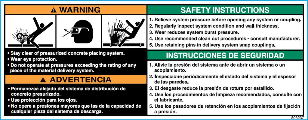
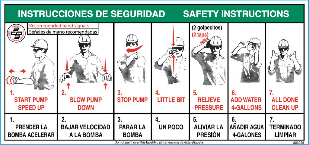
7 SAFETY DECALS OPERATION and MAINTENANCE Decals and placement of decals are standardized by the Concrete Pump Manufacturers Association (CPMA) for your protection. They are placed at appropriate areas on the concrete pump to be constant warnings of dangers. Know and adhere to the information they provide. Contact REED Customer Service for complimentary replacements of safety decals, shipping charges may apply. DECALS PLACED NEAR CONTROL BOX AREA 7 of 61

8 8 of 61


9 DECALS PLACED NEAR HOPPER GRATE AREA 9 of 61


10 DECALS PLACED NEAR WATERBOX AREA OPERATION and MAINTENANCE DECALS PLACED NEAR OUTRIGGER CONTROL AREA 10 of 61

11 DECALS PLACED NEAR HOPPER OUTLET AREA 11 of 61


12 DECALS PLACED ON SIDE PANEL AREA OPERATION and MAINTENANCE 12 of 61


13 13 of 61
14 OPERATION OPERATION and MAINTENANCE OPERATOR QUALIFICATIONS Everyone involved with the operation, maintenance, inspection, and repair of the concrete pump MUST READ and UNDERSTAND this operation manual and the accompanying Safety Manual. The following are a few general warnings for operator qualifications outlined in the Safety Manual. Individuals who cannot read and understand this operation manual, Safety Manual, signs, warnings, notices, and operating instructions, in the language in which they are printed, must not be allowed to operate the concrete pump. Only qualified, experienced, and trained personnel may be allowed to operate the concrete pump. Operation, maintenance, inspections, and repair must only be made by qualified, experienced, and trained personnel. Obey all applicable local and government statutes and regulations applying to safe operation and towing of concrete pumps. 14 of 61
15 PRODUCT DESCRIPTION OPERATION and MAINTENANCE The operation of the concrete pump encompasses the use of hydraulic and electrical systems. The concrete pump is designed to safely pump wet concrete through a delivery system of pipes and hoses within its published ratings and specifications. Stability of the concrete pump during operation is provided by the outriggers and front jack. Controls for the outriggers are located on the sides of the concrete pump. The pumping system employs a S-Tube design valve system. This system incorporates material cylinders linked to hydraulic cylinders that cycle alternately. With concrete material in the hopper and the pump operating, a material cylinder retracts, drawing material into the cylinder. At full retraction of the cylinder, a signal is sent to both the S-tube swing cylinder and the drive cylinder directional valves causing the s-tube to shift position to the fully loaded material cylinder and the drive cylinders to change direction. The concrete piston of the loaded cylinder then pushes the material through the s-tube and into the delivery lines. The shifting from one cylinder to the other cylinder takes place providing a continuous flow of material through the delivery piping system. The pump can be operated at the control panel or can be operated from the remote control. The hydraulic oil flow created by the hydraulic pump pushes the drive cylinder pistons inside the drive cylinders (1) alternately back and forth. Because the drive cylinders and concrete pistons (2) inside the concrete cylinders (3) are linked together, the pistons move synchronously. When a drive cylinder retracts along with the concrete piston, concrete will be sucked from the hopper into the concrete cylinder. Simultaneously, the other drive cylinder and concrete piston are extended toward the hopper. The concrete piston will push concrete from the concrete cylinders through the S-Tube (4) and out to delivery system (5). Next, the pump switches at the end of the stroke, causing the s-tube valve to shift to the other concrete cylinder which has sucked and filled the cylinder with concrete, starting the next cycle. Reverse pumping links the concrete piston in the suction stroke and S-Tube valve to suck concrete from the s-tube instead of the hopper. As a result, the concrete piston pumps concrete into the hopper. The power for operation of the concrete pump is provided by the engine, which drives the 15 of 61
16 hydraulic pumps. OPERATION and MAINTENANCE All functions for operation of the concrete pump can be accomplished from the local controls mounted on the side of the unit. Optional hand-held cable or radio remotes enable the pump to be operated away from a remote distance. HYDRAULIC SYSTEM DESCRIPTION The hydraulic system of the concrete pump consists of three separate circuits and although integrated, each is designed to perform a particular function within the operation of the concrete pump. The three circuits utilized are: Main Pump Circuit Controls operation of the hydraulic drive cylinders. S-Tube Shift Circuit Controls operation of shifting the s-tube from one material cylinder to the other. Auxiliary Circuit Controls the operation of the agitator and other auxiliary equipment. For the purpose of making the operation of each circuit easier to understand, they are being described separately. MAIN PUMP CIRCUIT The main hydraulic pump is a variable displacement axial piston pump of swashplate design. The pistons run along the swashplate which is capable of being tilted. This tilting changes the angle of the swashplate and thus the stroke length of the pistons, which in turn varies the displacement of fluid. The larger the angle of the swashplate, the greater the flow. The angle of the swashplate is varied by the volume control that works in conjunction with the load sense feature of this pump. The main hydraulic pump is driven directly by the engine or electric motor. When the engine is running, PUMP switch in the OFF position and the VOLUME control minimized, there is no demand placed on the pump. This is referred to as the pump being de-stroked, meaning, it is only producing a minimal amount of flow to enable the lubrication of the pump. This lubrication exists regardless of whether the engine is at idle or maximum RPM. The main pump circuit is equipped with a manifold that is drilled and ported to accommodate the relief valve, check valve, flow control and the pilot operated directional valve. The cycle valve is a directional spool valve with electro hydraulic solenoid operation. Its purpose is to direct the flow of oil from the main hydraulic pump to one or the other hydraulic drive cylinders. To energize the pump circuit, use the adjustable throttle control to set the engine speed at maximum RPM. Open the VOLUME control to any range from 0 to FULL. In so doing, the load 16 of 61
17 OPERATION and MAINTENANCE sense is alerted to the demand and places the pump on stroke. The pump will now produce the flow in proportion to the amount by which the volume control has been opened. Since the PUMP switch is OFF, the flow from the hydraulic pump is fed to the main directional valve, thru the valve, and then returns to the hydraulic tank. To energize the cycling circuit, the PUMP switch must be ON. When this is done, an electrical signal is generated which in turn energizes the coils of the main directional pilot valve and also activates the S-Tube directional valve. The material pumping action is the result of the two material cylinders cycling on an alternate basis. This alternating cycling is controlled by an electrical signal that is generated by the proximity sensors located in the flush box at the end of each material cylinder s suction or retraction stroke. As the piston coupler passes under the proximity sensor, it generates an electrical input signal that is sent to the logic controller, designed to control the alternating action of the material cylinders and to synchronize the movement of the s-tube. The output signal from the logic controller is used to energize the coils of the main directional pilot valve as well as that of the s- tube directional valve. As protection to the main pump circuit against excessive pressure, a relief valve has been installed and set. Thus when the system pressure reaches the maximum factory settings, the relief valve opens directing the oil back to the tank. 17 of 61
18 MAIN PUMP CIRCUIT OPERATIONAL SEQUENCE It can be noted in the schematic and the diagram below that the main pressure and flow is only directed to one side of the hydraulic drive cylinder. In this instance, it is directed to the head side or piston side of the double acting drive cylinder. The hydraulic drive cylinders are identical. Because only one cylinder is pressurized at a time, a means is required to assist in the retraction of the opposite cylinder. This is accomplished by connecting the rod sides of the cylinders together, forming a slave loop. In so doing, the hydraulic fluid that exists in the rod side of the extending cylinder (CYL A ) is transferred to the rod side of the other cylinder (CYL B ) causing it to retract simultaneously. The oil in the head side of CYL B is then forced out as it retracts and free flows through the directional valve back to the hydraulic tank or system. With this arrangement of connecting the two cylinders together, it is possible for various reasons, such as leakage around the piston seals, that more oil exists on the rod side of the cylinder than is required. When this condition exists, some hydraulic oil remains at the rod end of the cylinder being extended while the other cylinder is fully retracted. As a result, the cylinder will not completely extend and thus short strokes, which will also happen to the other cylinder on the next cycle. This condition can be corrected by actuating and holding the STROKE CHANGE switch on the electrical control box until extending cylinder is fully extended. Hydraulically, this is accomplished by use of the check valves installed on both cylinders. By holding the STROKE CHANGE switch, you have interrupted the cycle and are forcing more oil into the head side of the extending cylinder. Since that cavity is full, pressure is built up in the rod side of the fully 18 of 61
19 OPERATION and MAINTENANCE retracted cylinder, which unseats the head-side check valve and forces the excess oil out of the slave loop and back to the tank. Once the extending cylinder has reached its full stroke, regular operation can continue. Short stroking can also occur from incorrect proximity sensor location or leaking check valves. S-TUBE CIRCUIT Since there is only one outlet for the pumping material, a means is required to transfer the material from the material cylinder to the outlet and into the delivery line. To accomplish this, an s-tube is installed in the hopper. Since there are two material cylinders and one s-tube, the s-tube must be shifted from one material cylinder to the other, whichever one is loaded with the pumping material. The s-tube shift hydraulic circuit is of the open center type, meaning that when the control valves are in the neutral position, the internal passages of the valves are open, allowing the hydraulic fluid to return to the tank. With the engine running the hydraulic pump is operating, producing a flow of oil which, with no control energized, will pass through the shift circuit on its way back to tank. To meet the flow and pressure requirements of the shift circuit, one section of a tandem pump is used. Note: a single pump may be used if unit is not required for auxiliary equipment. The tandem hydraulic pump is of the gear pump design with a fixed displacement, meaning it is designed to constantly produce the same displacement at a pre-set maximum, depending on engine rpm. The tandem gear pump is directly connected to and driven through the main hydraulic pump. In addition to the hydraulic pump, the s-tube shift circuit consists of a manifold, an accumulator, solenoid valve cartridges, a solenoid directional valve, and 1 or 2 hydraulic shift cylinders. The following is offered to describe the function of each in the system. S-TUBE CIRCUIT MANIFOLD Like the main hydraulic circuit, the shift circuit is also equipped with a manifold block. It contains an unloader cartridge, relief cartridge and solenoid valve cartridges. A solenoid operated directional valve is mounted on top of the block and a s-tube selector control valve is located on front of the block. Each of these components is designed to perform a particular function in the swing circuit as explained in the following descriptions: RELIEF CARTRIDGE This cartridge is used to divert the pump flow from going to the accumulator once its capacity has been reached, directing it back to tank. It becomes operational when the unloader cartridge setting has been reached, acting as a dump valve. UNLOADER CARTRIDGE This pressure sensitive cartridge is used to protect the system from excessive pressure and to limit the amount of pressure being applied to the accumulator by hydraulically signaling the relief cartridge to open once the unloader setting has been reached. The unloader will also redirect the oil back to the accumulator when it senses a drop in system pressure, 19 of 61
20 when the hydraulic cylinder shifts for example. SOLENOID VALVE CARTRIDGE There are two (2) of these cartridges used in the circuit. Both, which may be referred to as a dump valve, are designed into the circuit as SAFETY VALVES. Their purpose is to automatically relieve pressure from the shift circuit as commanded by the emergency stop circuit. At start up, the normally open cartridges are open to tank so the shift circuit can not build any pressure. When the emergency stop circuit is reset, an electrical signal is generated which energizes the solenoids, closing the cartridges and allowing the shift circuit to pressurize. When the emergency stop function is activated or the key switch turned off, the power is taken away from solenoids, causing the cartridges to open and dump shift circuit pressure back to tank. SOLENOID DIRECTIONAL VALVE This valve is a directional control valve that is shifted by electronically activated solenoids. Its purpose is to direct the flow of oil stored in the accumulator to one or the other end of the shift cylinder based on the signal received by the logic controller that was generated by the proximity sensor. SHIFT BALL VALVE This is a manual ball valve and is used to control the speed of the s-tube shift. with valve fully opened, the flow is unrestricted, causing a fast hard shift of the s-tube. When the valve is closed, the shift is slower as the flow must now pass through an orifice. ACCUMULATOR The accumulator is incorporated into the shift circuit to provide instant pressure and volume for the shifting of the s-tube, which cannot be obtained under normal circumstances. An accumulator is a hydraulic reservoir that retains the hydraulic fluid under high pressure. The accumulator contains a rubber bladder on the inside of the reservoir. The bladder is pre-charged with dry nitrogen. In the application of the shift circuit, the hydraulic fluid is pumped into the accumulator at a higher pressure than that inside the bladder. This compresses the bladder building up high pressure within the accumulator that is retained until released. 20 of 61
21 S-TUBE CIRCUIT OPERATIONAL SEQUENCE In the operational sequence of the shift circuit with the engine at full RPM, the tandem pump is producing its rated displacement. The flow is going through the system and is being dumped or directed back to the tank thru the solenoid cartridges of the s-tube circuit manifold. When the HORN/RESET switch is placed to RESET, an electrical signal closes the solenoid cartridges. When this occurs the hydraulic fluid is now directed to the accumulator where it starts compressing the bladder and building up pressure. When the pressure in the shift circuit reaches a setting of the unloader valve, the unloader valve activates causing the relief cartridge to open. The open relief valve now directs the oil flow from the pump back to the tank instead of continuing to pressurize the accumulator. A check valve retains the pressure in the swing circuit and prevents the fluid from going back into the pump line. In the main pump circuit description it was described how an electrical signal was generated by the proximity sensor which was sent to the logic controller and used to control the alternating action of the hydraulic drive cylinders. This same signal is also used to shift the s-tube so that its movement is synchronized with that of the hydraulic drive cylinder, shifting the s-tube to the material cylinder which is ready to extend (normal forward operation). The electrical signal activates the solenoid coil of the directional valve, shifting the spool to the appropriate side. The accumulator then releases, exhausting the fluid which flows through the directional valve and is directed to the appropriate side of the shift cylinder. As soon as the shift is made the accumulator is refilled immediately and the sequence starts all over again. AUXILIARY CIRCUIT The auxiliary circuit has been designed and installed for the purpose of operating the hydraulic function of the auxiliary equipment on the unit, primarily the agitator. This function is that of the agitator rotation for mixing the material in the hopper and feeding of the concrete cylinders. The flow and pressure requirements for the auxiliary circuit are met by employing the second stage or section of the same tandem pump used on the s-tube shift circuit. With the engine running and throttle set to maximum RPM, the flow from the tandem pump is directed to a single spool directional control valve. This circuit also utilizes a solenoid valve cartridge or dump valve, designed as a safety valve with the purpose of preventing flow to the auxiliary circuit as commanded by the emergency stop circuit. At start up, the normally open cartridge directs the oil flow from the tandem pump to tank, prohibiting function of the auxiliary circuit. When the emergency stop circuit is reset, an electrical signal is generated to energize the solenoid, closing the cartridge and blocking flow directly back to tank, instead allowing the flow to the single spool directional control valve for operation. The directional control valve has relief cartridge to protect the system against excessive pressure When the valve lever is activated the agitator will rotate in forward direction as hydraulic fluid is directed to that side of the motor. Rotation can be reversed by moving lever in other direction. 21 of 61
 push button switches are provided and are used to control the 460V electric motor.")
22 CONTROLS MAIN ELECTRICAL PANEL CONTROL This is two (2) position switch used to control energizing the main electrical hi-voltage system. Turn handle to the ON position to activate system from the external source. 2. MOTOR CONTROL SWITCH Two (2) push button switches are provided and are used to control the 460V electric motor. To START green button and hold until motor starts, then release button. To STOP motor, PUSH red button until motor stops, then release. 22 of 61
 position toggle switch and is used to control the cycle direction of the concrete pump. CENTER position of toggle is PUMP-OFF.")
23 CONTROLS 8 OPERATION and MAINTENANCE CABLE REMOTE (RADIO REMOTE OPTIONAL, CONTACT REED FOR INFORMATION) 1. PUMP DIRECTION SWITCH This is a three (3) position toggle switch and is used to control the cycle direction of the concrete pump. CENTER position of toggle is PUMP-OFF. Move toggle to UP Position to activate PUMP-ON and FORWARD cycling. Move toggle in DOWN position for REVERSE cycling. 2. CONTROL SWITCH This is a two (2) position toggle switch and is used to select the pump control location. Move toggle to LOCAL to enable operation of concrete pump for main stationary panel. Move toggle to REMOTE for operation using the remote control. 3. INDICATOR LIGHT This Green Light, located above and below the switches is used, when lit, to indicate the position of the toggle. The yellow light will light up in REMOTE mode. 4. HORN/RESET this is a momentary toggle switch and is used to reactivate the control and pump circuit after machine has been shut down using the EMERGENCY STOP switch. Once the emergency stop has been depressed it will be necessary to the pull out switch and move toggle of HORN switch momentary to RESET 5. CONTROL ON INDICATOR This is a green indicator light, when lit denotes control circuit is engaged 6. TEST-CYL A, CYL B-SWITCH This is a three (3) position momentary toggle switch. It is used for the purpose of pressure test of jogging the position in cylinder A of B. Move toggle to desired position. Toggle will return to center when released. 7. MAIN POWER SWITCH This is a three (3) position key switch. Turn key to the ON position to power control box. Shut down power by turning key to OFF position. 8. EMERGENCY STOP This is an emergency switch and is used to shut down the pump in an emergency situation. It is of the push-pull type, Depress PUSH knob in to STOP operation. PULL knob out to REACTIVATE system. NOTE: the HORN/RESET must be switched one time to restart pump operation. 23 of 61

24 REMOTE CONTROL FAMILIARIZION A remote control pistol grip console is provided and is used to enable the operation of the concrete pump away from the immediate vicinity of the unit. The remote is equipped with an umbilical cord that plugs into the side of the main control box. The console consists of the following functions: 1. EMERGENCY STOP SWITCH 1 This is an emergency switch and is used to shut down the pump in an emergency situation. It is of the push-pull type. Depress, PUSH knob in to STOP operation. In this position, knob will light. PULL knob OUT to REACTIVATE system HORN/RESET This is a momentary toggle switch and is used to activate the control and pump circuit after the machine has been shut down using the EMERGENCY STOP switch. Once the emergency stop has been depressed, it will be necessary to pull out switch and move toggle of HORN switch momentary to RESET position. 3. INDICATOR LIGHT This green indicator light will be lit when remote circuit is energized. 4. PUMP SWITCH This is a three (3) position toggle switch and is used the cycle direction of the concrete pump. CENTER position of the toggle is PUMP-OFF. Move toggle in UP position for REVERSE cycling. Move toggle DOWN position to activate PUMP-ON of 61


25 VOLUME CONTROL KNOB adjusts volume output of the material. COUNTERCLOCKWISE To INCREASE Volume CLOCKWISE To DECREASE Volume Do Not Adjust Volume Output by Adjusting RPM Adjust Volume Output by Adjusting Volume Control Knob AGITATOR CONTROL controls agitator ON/OFF and FORWARD REVERSE functions. 25 of 61
26 SOFT SHIFT HARD SHIFT SHIFT BALL VALVE controls the speed of the S-Tube shift. Hard Shift - rotate ball valve lever counter clockwise to fully open the valve and allow the hydraulic flow to bypass a restrictive orifice. Soft Shift - turn ball valve lever clockwise closing the ball valve and directing the hydraulic fluid through an orifice. This position may be used when a slurry is being pumped or when the machine is being cleaned out. 26 of 61
27 TOWING OPERATION and MAINTENANCE Refer to the Safety Manual for towing safety precautions not limited to the following guidelines: Ensure Unit Is Securely Attached Before Driving Refer To Tow Hitch Instruction Manual Tow Slowly and Safely Depending On Road Conditions Overturning May Occur At Unsafe Speeds NEVER Exceed 55 MPH Maintain a Sufficient Distance for Braking Overturning May Occur At Unsafe Stopping Distances 27 of 61
28 SET-UP OPERATION and MAINTENANCE Refer to the Safety Manual for set-up safety precautions not limited to the following guidelines: Ensure Machine Can Be Safely Operated In Set-Up Location Away From Hazards and Dangers Away From Slopes and Excavations Position Machine On As Solid and Level Ground As Possible Place Outrigger Pads Below Outrigger Jacks If Necessary Secure Jack Positions with Outrigger Pins and Locks Not Using Outriggers Voids Warranty Damage Will Occur If Outriggers Are Not Used 28 of 61
29 PRIMING OPERATION and MAINTENANCE Priming consists of pumping a lubricant to coat the s-tube and delivery lines to assist the initial concrete material in getting through the delivery lines and avoid blockages. Once the delivery lines are full of concrete, that material will supply the lubrication necessary for the material to flow through the delivery lines. However, it is imperative that a primer be used ahead of the initial concrete material to pre-lubricate the lines in order to avoid blockages. A suggested grout to use for priming and lubrication may consist of 2 parts sand and 1 part cement and mixed to a consistency of a thick cream. The amount of grout required depends on the length of the delivery line as well as the material being pumped. Operator experience will eventually indicate the amount to be required. In addition to grout, there is a wide variety of priming products available on the market. 29 of 61
30 PUMPING OPERATION and MAINTENANCE Everyone involved with the operation, maintenance, inspection, and repair of the concrete pump MUST READ and UNDERSTAND this manual and the Safety Manual. Refer to the Safety Manual for pumping and blockages safety precautions not limited to the following guidelines: Perform Required Inspection, Lubrication, and Maintenance Before, During, and After Pumping Operations Do Not Remove Hopper Grate Or Other Safety Components Do Not Insert Body Parts into Hopper, S-Tube, or Waterbox Or Other Moving Components Turn Pump ON Only When Hopper Is Full Of Concrete Ensure the following conditions are met before activating pump: o PUMP Switch Is OFF o VOLUME CONTROL Is Set To MINIMUM o AGITATOR Control Is In OFF Position o EMERGENCY STOPS Are Not Activated o Controls On LOCAL Position 30 of 61
31 PUMPING Continued OPERATION and MAINTENANCE 1. Turn KEY operated SYSTEM POWER Switch to ON 2. Press GREEN START Button to start electric motor. 3. Activate the HORN/RESET to prepare the concrete pump for operation 4. Adjust VOLUME CONTROL to low output when starting pumping operations 5. Switch PUMP Switch to ON to pump concrete when hopper is full, maintain full level 6. Turn PUMP Switch to REVERSE to reverse the pumping action if necessary. REVERSE function is typically used to relieve pressure in the delivery in the event of a blockage 7. Turn PUMP Switch OFF to stop cycling and stop pumping concrete 8. In the event of an emergency, push the EMERGENCY STOP Button IN to stop all functions of the concrete pump. Pull the EMERGENCY STOP Button OUT to enable system to reset; Horn/Reset function must be activated to reset pump operation. 31 of 61
32 CLEANING Do Not Remove Hopper Grate Or Other Safety Components Do Not Insert Body Parts into Hopper, S-Tube, or Waterbox Or Other Moving Components 1. Set VOLUME CONTROL to LOW 2. Pump as much material as possible out of the delivery system 3. Turn PUMP Switch OFF 4. Disconnect delivery system. Disconnect the line right after the reducer if a reducer is used 5. Open hopper door and empty hopper 6. Flush out hopper, S-Tube, and cylinders with water 7. Place DIRECTION Switch in REVERSE. Place no more than two feet of the water hose into the pump discharge outlet then turn the PUMP switch ON Water will drain into the material cylinders and as pump cycles, any sand and rocks will be forced out through the open clean out door. 8. Stroke the pump to make sure all sand and other material has been cleaned out, and then turn the pump off. 9. Close the hopper clean out door. 10. Place a clean out sponge into the disconnected delivery line. Reconnect the line to the hopper outlet or reducer with the sponge inserted as close to the hopper outlet as possible. 11. Fill the hopper with water. Place the DIRECTION Switch to the FORWARD position and check that VOLUME control is set at low speed. Turn PUMP Switch ON and cycle the pump until the sponge passes through the entire delivery system into a sponge catcher 12. Turn off the pump and allow the water to drain from the system 13. Clean up the remaining areas of the machine as needed 14. After clean up is complete lubricate all grease points to expel any grout before it cures 32 of 61
33 MAINTENANCE RECOMMENDED MAINTENANCE PRACTICES MAINTENANCE MANAGEMENT Schedule lubrication and maintenance inspections to anticipate maintenance issues. Maintenance management requires the assignment of responsibilities to individual personnel, training of personnel, keeping of records, and the exercise of judgment. INSPECTION AND LUBRICATION CHECKLISTS AND OPERATOR REPORTS Utilize checklists for scheduled inspection and lubrication and maintain a written record regarding observations and actions performed. Maintain all scheduled maintenance reports by the operator listing any malfunctions and observations. PUMP HISTORY FILE NOTING PUMP SERIAL NUMBER File the operator reports, inspection and lubrication checklists, shop repair, work orders and tickets, parts replacement and pump usage records. This file should also include the parts book for the specific serial number and engine. ANNUAL REVIEW Review the history records of each unit once every year to find evidence of repetitive failures, adjustments, problems, or excessive wear so that action can be taken to minimize breakdowns and reduce excessive maintenance costs. A review of the machine history will help in the stocking of spare parts and assemblies in advance of a possible need. Engine Manufacturer Maintenance Schedule Must Be Followed Read Engine Manufacturer Manual REED has provided only general guidelines regarding engine maintenance, and will not cover engine warranty claims. Accumulator Pressure Must Be ZERO Before And During Any Maintenance Procedures Engine Must Be Turned OFF and Lockout / Tagout Procedures Must Be Followed Before And During Any Maintenance Procedures 33 of 61
34 GENERAL MAINTENANCE AREAS OPERATION and MAINTENANCE Perform scheduled inspections to identify and detect any potential problems. The list presented should be inspected and checked on a regular basis and is a recommended minimum. TRAILER Frame integrity, visually check welds, cracks Torsion axle secure Wheels and tires, lug nuts tight, tire pressure Electric brakes, breakaway switch connected Front jack stand handle turns easily, smoothly Manual jacks slide freely, lock pins in place Lighting good condition, operational ENGINE (refer to engine manufacturer manual) Inspect mounts, bolts, brackets and belts Oil and coolant fluids at proper level, check for leaks Fuel system, tank mounting, filter condition, leaks, damaged lines Battery hold down, condition, tightness of cables Key switch, indicator lights Throttle control functional Air cleaner and muffler securely mounted PUMP CELL Visually check for structural damage, cracked welds Hydraulic drive cylinders in good condition, secure, check for leaks Material cylinders secure, tie rods tight Water box structurally sound, clean, cover in place S-Tube shift mechanism structurally sound, all pins and retainers in place Hydraulic shift cylinder(s) in good condition Bearing housing, seals etc. in good condition Hydraulic hoses secure no leaks HOPPER ASSEMBLY Visually check for structural damage, cracked welds S-Tube secure, in good condition Check condition of wear plate, wear ring, seals Check connection of s-tube to outlet, seals, bearing Hopper drain is functional Cleaning hopper Zerk fittings accept grease 34 of 61
35 OPERATION and MAINTENANCE MAIN CONTROLS Control box in good condition, sealed, not damaged All toggles in good condition, stay in position or momentarily return to center Control identification in good condition, legible Gauges in good condition REMOTE CONTROLS Control console in good condition, not damaged Switch in good condition Cord in good condition, no cuts, securely mounted to box HYDRAULIC SYSTEM Hydraulic tank securely mounted, covers tight Breather, filler cap and strainer in place, level sight gauge in proper condition Check filter condition indicators Hydraulic oil cooler securely mounted, connections tight Check accumulator condition, mounting brackets & clamps Hydraulic fluid to proper level and clean All hoses and tubing secure, check for leaks 35 of 61
36 LUBRICATION The REED concrete pump is equipped with several components that require frequent lubrication. These areas involve the s-tube shifting mechanism, swing components, the shift and outlet bearings and agitator. to insure the economical service and the long life of these components, grease fittings are installed at each point. Rapid wear and possible shutdown will result if the unit is operated with inadequate lubrication. Follow the recommendations stated herein, and if needed increase the application of lubricants above these recommendations when the equipment is subject to heavy usage. MINIMUM LUBRICATING INTERVALS Recommended lubrication intervals are based on normal use under normal conditions. The lubrication interval must be increased to meet more challenging uses and uses which subject the equipment to high and/or unusual concentration of forces. The lubrication interval must be increased if the pump has been exposed to environmental conditions such as low humidity, high humidity, excessive dust, high temperatures, low temperatures, heavy rainfall, long term storage, ocean air, etc 1) every hour of operation 2) after completion of every job All lubrication points must be greased on each and every interval as recommended. TYPE OF LUBRICANT Use EP grease, extreme pressure grease available for wheel bearings, general purpose grease, Shell Alvania EP (LFH2), or equivalent if this lubricant is unavailable in your area Do NOT use Moly grease, grease with Moly additives LUBRICATION POINTS The following graphics are for REFERENCE ONLY. 36 of 61
 SHIFT CYLINDERS 37 of")
37 S-TUBE SHIFT LUBRICATION OPERATION and MAINTENANCE IF EQUIPPED WITH DUAL (2) HYDRAULIC SHIFT CYLINDERS, RELIEVE SHIFT CIRCUIT HYDRAULIC PRESSURE TO PROPERLY GREASE HYDRAULIC SHIFT CYLINDERS AND BELL CRANK S-TUBE BEARING GREASE POINTS BELL CRANK AND SHIFT CYLINDER GREASE POINTS NOTE: RELIEVE S-TUBE CIRCUIT PRESSURE BEFORE APPLYING GREASE IF EQUIPPED WITH DUAL (2) SHIFT CYLINDERS 37 of 61

38 S-TUBE OUTLET LUBRICATION S-TUBE OUTLET GREASE POINTS 38 of 61


39 AGITATOR LUBRICATION OPERATION and MAINTENANCE HYDRAULIC MOTOR SIDE GREASE POINT NON-HYDRAULIC MOTOR SIDE GREASE POINTS 39 of 61
40 HYDRAULIC SYSTEM OPERATION and MAINTENANCE Hydraulic pumps are used to supply the flow of oil necessary to operate actuators of the concrete pump. Contamination of the Oil Is the Leading Contributor to System Malfunctions Extreme care must be exercised to prevent contaminants from entering the system. Always cap or plug open ports and hydraulic lines. HYDRAULIC TANK The hydraulic tank is equipped with an access cover with breather and magnetic suction strainers inside the tank. A sight and temperature gauge is installed on the tank to determine the fluid level and temperature inside the tank. The tank is also equipped with drain valve. In addition to the magnetic suction strainers, filtration is accomplished by use of a hydraulic return filter located on top of the hydraulic tank. The return filter is equipped with an indicator gauge to monitor filter restriction. An oil cooler is adjacent to the engine cooling unit. 40 of 61
41 HYDRAULIC SYSTEM MAINTENANCE ITEM DESCRIPTIONS FLUID Check fluid level and oil clarity daily with sight gauge provided. Maintain level at full mark. Add hydraulic oil through the return filter fill port when necessary. TANK BREATHER Clean every 50 hours of operation. Remove from tank, clean with solvent and air blow dry. FILTER Change after first 50 hours of operation. Thereafter change every 250 hours of operation or when condition gauge indicates change is necessary. HYDRAULIC TANK Change oil in tank every 500 hours of operation or yearly, whichever comes first. HYDRAULIC FLUID The hydraulic system is filled with Shell Oil Company TELLUS #46. It is to be used in ambient temperatures of F (4-32 C). The normal fluid temperature will range from F (38-75 C). For ambient temperatures of 90 F (32 C) and above, use fluid designated with an ISO rating of 68. Use ISO 32 for ambient temperatures of 32 F (4 C) and below. Use Only Shell Tellus 46 or Equivalent Never Mix With Other Types of Fluids Always Use Clean and New Fluid Using impure or other type of fluids not specified will contaminate the hydraulic system and lead to eventual system malfunction and/or damage. 41 of 61

42 ADDING HYDRAULIC FLUID OPERATION and MAINTENANCE Exercise extreme care when adding fluid to the hydraulic tank to avoid contamination. To prevent any dirt or water from entering the hydraulic tank, thoroughly clean area around filter fill port. Remove filter fill port. Fill system with new clean hydraulic fluid. If a pump is used to transfer the fluid, ensure the pump filter is clean. If pouring fluid from a container, pour it through a fine wire mesh screen, 200 mesh or finer. Replace filter fill port immediately after filling tank to proper level. FILTER SERVICING Do Not Use Cloth for Straining Fluid Lint Is a Contaminant Harmful To the Hydraulic System FILTER INDICATOR FILL PORT FILTER ELEMENT Hydraulic filters provide a means of continuous hydraulic fluid filtration in an effort to prevent recirculation of contamination which will cause rapid wear and component breakdown. The filter is equipped with a condition indicator gauge which should be checked daily and the element changed when indicated. 42 of 61
43 To change the filter elements: OPERATION and MAINTENANCE 1. Shut off machine allowing accumulator system to depressurize 2. Wipe clean any dirt and grime from area surrounding filter housing 3. Loosen the bolts holding on top plate of filter 4. Carefully remove cover so as not to damage the gasket 5. Remove bypass valve and element 6. Discard only element and discard responsibly 7. Install bypass valve and new element and replace cover 8. Wipe clean any contaminants around high pressure filter 9. Remove filter housing then remove and discard filter element 10. Check and replace o-ring or gasket if necessary 11. Replace filter element and install filter housing 12. Start up machine and observe for leakage Do Not Wash Out and Reuse Disposable Filter Elements CLEANING THE HYDRAULIC TANK The hydraulic tank should be drained and cleaned after 500 hours of operation or yearly, whichever occurs first, to assist in keeping the systems clean and in proper condition. 1. Shut off machine allowing the hydraulic system to depressurize 2. Place a suitable size container under the hydraulic tank drain fitting and then remove drain plug. 3. After draining, remove the access cover on the hydraulic tank being careful not to damage the gasket 4. Remove, disassemble and clean magnetic suction strainers before reassembly 5. Flush the inside of the hydraulic tank with a clean solvent and wipe clean with lint free cloths 6. Install suction strainers 7. Replace sight gauge 8. Install the tank drain plug and access cover with gasket 9. Replace the breather cap 10. Change the hydraulic system filter element 11. Refill the hydraulic tank with new clean hydraulic fluid 12. Start machine and check for leaks 43 of 61
44 COMPONENT REPLACEMENT When parts are worn, do not delay in replacement. Continued usage with worn parts may lead to damage of other components. This section is provided as a general guideline to assist in replacing major components that will wear. Please contact the REED Service Department or your local dealer for technical support. S-TUBE, WEAR RING, AND WEAR PLATE The sealing characteristics of the s-tube depend on the positive contact of the wear ring, located inside the s-tube, to the wear plate mounted inside of the hopper. the abrasiveness and friction of the concrete will cause wear and a breakdown of the sealing action. As this breakdown occurs, periodic adjustments to the s-tube can be made. This will help to improve the sealing quality; however, eventually the components will need to be replaced. Adjustment or parts are required if: s-tube concrete build up deep grooves have developed on the face of the wear plate and/or on the wear ring When the output volume at the end of the delivery line noticeably begins to decrease or eventually stops When the material being pumped is being forced back into the hopper under pressure Accumulator Pressure Must Be ZERO BEFORE AND DURING Any Maintenance Procedures Engine Must Be Turned OFF and Lockout / Tagout Procedures Must Be Followed BEFORE AND DURING Any Maintenance Procedures NOTE: The following graphics are for REFERENCE ONLY. 44 of 61
45 45 of 61
46 46 of 61
47 47 of 61
48 Accumulator Pressure Must Be ZERO BEFORE AND DURING Any Maintenance Procedures Engine Must Be Turned OFF and Lockout / Tagout Procedures Must Be Followed BEFORE AND DURING Any Maintenance Procedures 1. Turn off engine to shut down the system. Confirm gauges show no pressure. 2. Remove outlet bolts, remove outlet 3. Loosen bell crank pinch bolt (s), remove cotter pin, loosen s-tube nut 1 turn 4. Remove outlet seal housing followed by s-tube nut, spacer, bell crank, washer, swing ram(s) 5. Place a sling from an overhead hoist around the discharge end of s-tube to help support the tube. 6. Pry s-tube toward outlet, remove wear ring & thrust seal. The s-tube may be swung upside down for easy access to clean. Thrust seal groove must be properly cleaned Note: the s-tube may be removed from hopper for better access by removing flange bearing, seal and chromed outlet and hoisting it out of hopper 7. If wear plate is to be changed, remove wear plate mounting bolts. Pry wear plate from hopper using provided jack bolt. 8. Pry anti-chip rings out of hopper bore. Use caution not to damage chrome concrete cylinder. Clean anti-chip ring bore and wear plate area. Replace o-rings (if applicable). Test-fit new bolts in new wear plate, they should not protrude (grind if necessary). Apply small bead of silicone to outer diameter of anti-chip rings, install into hopper bore with split at bottom 9. Apply small amount of silicone to hopper-side of wear plate, and bolt-heads. Install wear plate, hand tighten bolts. Use a pair of bolts with nuts underneath new wear plate to adjust and align to concrete cylinders. Torque wear plate mounting bolts to 250 ft lbs, remove adjusting bolts. 10. Install new thrust seal & wear ring in s-tube. 11. Install shaft seal and flange bearing (if removed), torque bolts to 100 ft lbs 48 of 61
49 OPERATION and MAINTENANCE 12. Slide s-tube forward against wear plate, install washer, align/ mount bell crank, install spacer and castle nut. Do not tighten yet. 13. Replace outlet seals in proper orientation, apply grease and install outlet seal housing. Install outlet, torque outlet bolts to 100 ft lbs. Grease all zerk fittings for s-tube until grease comes out of seals. 14. Remove sling, tighten s-tube nut/bolt. It may be helpful to start machine and cycle s- tube to help new parts seat. Do final tightening to s-tube nut/bolt, install cotter pin/retainer, tighten bell crank pinch bolt (s). The nut should be as tight as possible without hampering the shift of s-tube S-TUBE ADJUSTMENT Accumulator Pressure Must Be ZERO BEFORE AND DURING Any Maintenance Procedures Engine Must Be Turned OFF and Lockout / Tagout Procedures Must Be Followed BEFORE AND DURING Any Maintenance Procedures The s-tube will require periodic adjustment as the wear parts wear in order to ensure the good contact and sealing characteristics of the wear plate and wear ring, as well as maintaining a constant squeeze of the thrust seal behind the wear ring. S-tube adjustment is performed by tightening the castle nut. Generally, the castle nut should be as tight as it can be without slowing or hindering the throw of the s-tube. 1. With engine off and no pressure showing on gauges, loosen the bell crank pinch bolts 2. Remove cotter pin and tighten castle nut one flat or to next cotter pin slot. 3. Start and cycle machine to ensure proper s-tube operation. Adjust further if necessary, following lock out tag out rule for each adjustment. 4. When adjustment has been satisfied, install cotter pin and tighten bell crank pinch bolts. 49 of 61

50 PISTON CUP AND GUIDE BAND REMOVAL/REPLACEMENT Because of the abrasiveness of the material being pumped, it will be necessary to periodically replace the piston cups. Signs and identifying systems of worn parts might be: Slurry of the material being pumped starts to appear in the flush box The water or lubricating oil in water box begins to rapidly lower level without any sign of leakage Operation is rough and erratic Accumulator Pressure Must Be ZERO BEFORE AND DURING Any Maintenance Procedures Engine Must Be Turned OFF and Lockout / Tagout Procedures Must Be Followed BEFORE AND DURING Any Maintenance Procedures 1. Drain all oil or water from the flush box. 2. Cycle machine using appropriate controls until one of the cylinders is completely retracted. Turn off engine and allow hydraulic systems to completely depressurize. 3. As a precaution, mark location of proximity sensor adjusting bracket. Remove proximity sensor cross bracket. 4. Mark the end of the piston coupler so that it can be placed in the same relation during reassembly. 5. Unbolt and remove top and bottom halves of coupler. Pry the piston assembly into flush box. 6. Disassemble and clean piston adapter and plate. Check flatness of plate, replace if necessary. 7. Install and grease new guide band. Push adapter/guide band squarely into cleaned and greased concrete cylinder. 8. Install coupler using medium strength Loctite on bolts and torque to 90 ft lbs. 9. Start and completely extend the adapter and guide band to hopper side. Jog s-tube if necessary to expose fully extended piston adapter. 10. Turn off engine and allow hydraulic systems to completely depressurize 50 of 61
OPERATION and MAINTENANCE
 OPERATION and MAINTENANCE (909) 287-2100 INTRODUCTION...2 WARRANTY...3 WARRANTY CLAIM FORM... 4 SAFETY...5 SAFETY ALERT SYMBOLS AND SIGNAL WORDS... 5 LOCKOUT / TAGOUT... 6 GENERAL SAFETY GUIDELINES...
OPERATION and MAINTENANCE
 INTRODUCTION... 2 WARRANTY... 3 WARRANTY CLAIM FORM... 4 SAFETY... 5 SAFETY ALERT SYMBOLS AND SIGNAL WORDS... 5 LOCKOUT / TAGOUT... 6 GENERAL SAFETY GUIDELINES... 6 SAFETY DECALS... 7 OPERATION... 14 OPERATOR
REED ROCK MASTER A40HP TRAILER CONCRETE PUMP
 PAGE 00 PREVENTATIVE ENANCE How good is any of the equipment you own? It is only as good as it is AINED. Even the finest equipment manufactured requires attention and care. The 02 MODEL A40HP is no different.
REED MODEL: B50 TRAILER CONCRETE PUMP
 OPER. PAGE 00 PRE-OPERATION INSPECTION The CONDITION of the unit prior to start-up is a very IMPORTANT factor as it directly affects the operator s safety as well as those around him. It should be a common
Hydraulic Long Jacks
 Operating Instructions & Parts Manual Hydraulic Long Jacks Model 44915 44930 44940 44980 44981C (Air option) Capacity 1-1/2 Ton 3 Ton 4 Ton 8 Ton 8 Ton Models 44915, 44930, 44940 & 44980 Model 44981C U.S.
Hydraulic Wheel Dolly
 Hydraulic Wheel Dolly Operating Instructions & Parts Manual Model Number HW93765 Capacity 3/4 Ton Made in the U.S.A. This is the safety alert symbol. It is used to alert you to potential personal injury
Hydraulic Truck Jack
 Operating Instructions & Parts Manual Hydraulic Truck Jack Model Capacity 23221C 22 Ton 23222C (Low Profile) 22 Ton 23301 30 Ton Models 23221C & 23222C Model 23301! U.S. Patent No's. 5,341,723 & 5,94,912
2244 West McDowell Road Phoenix, AZ RACE (fax) INSTALLATION INSTRUCTIONS FOR
 INSTALLATION INSTRUCTIONS FOR") 2244 West McDowell Road Phoenix, AZ 85009 602-257-9591 1-800-274-RACE 602-340-8429 (fax) www.hughesperformance.com INSTALLATION INSTRUCTIONS FOR HP2215 TH400 3-SPEED TRANSBRAKE VALVE BODY KIT Please read
2244 West McDowell Road Phoenix, AZ 85009 602-257-9591 1-800-274-RACE 602-340-8429 (fax) www.hughesperformance.com INSTALLATION INSTRUCTIONS FOR HP2215 TH400 3-SPEED TRANSBRAKE VALVE BODY KIT Please read
APCO CRF-100A RUBBER FLAPPER SWING CHECK VALVES
 APCO CRF-100A RUBBER FLAPPER SWING CHECK VALVES Instruction D12043 June 2016 DeZURIK Instructions These instructions provide installation, operation and maintenance information for APCO CRF-100A Rubber
Operating Instructions & Parts Manual
 Swift Lift Hydraulic Service Jack Operating Instructions & Parts Manual Model Number ATD7341 Capacity 3-1/2 Ton U.S. Patent No's. 5,946,912 6,199,379! This is the safety alert symbol. It is used to alert
Fast Lift Service Jack, Low Profile
 Blackhawk Automotive is a Licensed Trade Mark Made by SFA Companies, Kansas City, MO Fast Lift Service Jack, Low Profile Operating Instructions & Parts Manual Model BH6023B Capacity 2 Ton! U.S. Patent
ACHL Series Pump. Operation and Maintenance Manual Air Driven, Hand Operated High Pressure Liquid Pump
 ACHL Series Pump Operation and Maintenance Manual Air Driven, Hand Operated High Pressure Liquid Pump Catalog: 02-9245ME February 2013 Model # Serial # Drawing # Order # Mfg. Date Table of Contents page
Air Actuated Hydraulic Bottle Jacks
 Air Actuated Hydraulic Bottle Jacks Operating Instructions & Parts Manual Model Number Atd-7412 Atd-7420 Capacity 12 Ton 20 Ton Atd Tools Inc. 160 Enterprise Drive, Wentzville MO 63385 Printed in China
Heavy Duty Engine Cranes
 Heavy Duty Engine Cranes Operating Instructions & Parts Manual Model Number Atd-7484 Atd-7485 (Foldable Legs) Capacity 2 Ton 2 Ton Model Atd-7484 Model Atd-7485 Atd Tools Inc. 160 Enterprise Drive, Wentzville,
OPERATIONS MANUAL LEVER CHAIN HOIST
 OPERATIONS MANUAL LEVER CHAIN HOIST IMPORTANT SAFETY INFORMATION Please read, understand and follow all safety information contained in these instructions prior to the use of this hoist. Retain these instructions
PENBERTHY MODELS GL AND GH GAS OPERATED JET PUMPS INSTALLATION, OPERATION AND MAINTENANCE INSTRUCTIONS
 Before installation, these instructions must be read carefully and understood. PRODUCT WARRANTY Emerson warrants its Penberthy products as designed and manufactured to be free of defects in the material
1250 LB. CAPACITY MECHANICAL WHEEL DOLLY
 1250 LB. CAPACITY MECHANICAL WHEEL DOLLY 67287 SET-UP AND OPERATING INSTRUCTIONS Visit our website at: http://www.harborfreight.com Read this material before using this product. Failure to do so can result
Hydraulic Wheel Dolly
 Hydraulic Wheel Dolly Operating Instructions & Parts Manual Model Number HW93766 Capacity 3/4 Ton Made in the U.S.A. This is the safety alert symbol. It is used to alert you to potential personal injury
before serial number 2214
 before serial number 2214 Contents Page Safety Rules... 3 Pre-operational & Safety Inspection... 4 Operating Instructions... 6 Transport... 12 Maintenance & Routine Service... 12 Specifications... 14 SAFETY
Before equipment use, please read this operation manual carefully. Serial Number: Date Purchased:
 Pushed & Geared Trolleys OPERATION MANUAL This operation manual is intended as an instruction manual for trained personnel who are in charge of installation, maintenance, repair etc. Before equipment use,
Long Chassis Hydraulic Service Jacks
 Model BH6011 Long Chassis Hydraulic Service Jacks Operating Instructions and Parts Manual Capacity 10 Ton Model BH6011 U.S. Patent No's. 5,946,912 5,341,723! This is the safety alert symbol. It is used
Hydraulic PTO Flow Device
 Safety, Operation, and Maintenance Manual WARNING Improper use of this tool can result in serious bodily injury This manual contains important information about product function and safety. Please read
Brake System H TX, H2.0TXS [B475]; H TX [B466] Safety Precautions Maintenance and Repair
![Brake System H TX, H2.0TXS [B475]; H TX [B466] Safety Precautions Maintenance and Repair](/thumbs/86/93834005.jpg "Brake System H TX, H2.0TXS [B475]; H TX [B466] Safety Precautions Maintenance and Repair") HMM180001 Brake System H1.5-1.8TX, H2.0TXS [B475]; H2.5-3.5TX [B466] Safety Precautions Maintenance and Repair When lifting parts or assemblies, make sure all slings, chains, or cables are correctly fastened,
HMM180001 Brake System H1.5-1.8TX, H2.0TXS [B475]; H2.5-3.5TX [B466] Safety Precautions Maintenance and Repair When lifting parts or assemblies, make sure all slings, chains, or cables are correctly fastened,
CLEAN ROOM DEVICES, LLC "WHERE TUBING AND FITTINGS COME TOGETHER"
 CLEAN ROOM DEVICES, LLC "WHERE TUBING AND FITTINGS COME TOGETHER" CRD600 Automatic Fitting Inserter OPERATIONS MANUAL VERSION 2.1 LAST EDITED 7.25.14 DOCUMENT NUMBER 001 cleanroomdevices.com 1 Table of
Operating Instructions & Parts Manual. Air/Manual Hydraulic Bottle Jacks
 J18124-M1_032015 Operating Instructions & Parts Manual Air/Manual Hydraulic Bottle Jacks Model J18124 J18204 Capacity 12 Ton 20 Ton U.S. Patent Nos. 6,012,377-5,946,912! This is the safety alert symbol.
Heavy Duty Bottle Jacks
 Heavy Duty Bottle Jacks Models: 10300 & 10500 10300 10500! This is the safety alert symbol. It is used to alert you to potential personal injury hazards. Obey all safety messages that follow this symbol
Low Profile Service Jack
 Low Profile Service Jack Model GMG29031 Capacity 3 Ton U.S. Patent No. 6,199,379! This is the safety alert symbol. It is used to alert you to potential personal injury hazards. Obey all safety messages
Deere G & GP Series Snow Wing Installation
 Deere G & GP Series Snow Wing Installation Model: Serial Number: Rev. 10/13 Rylind Manufacturing, Inc. 2801 Youngfield St Suite 250 Golden, CO 80401 Offices: 303-979-3548 Fax: 303-979-4730 www.rylind.com
Operating Instructions & Parts Manual
 Aluminum / Steel Hybrid Service Jack Operating Instructions & Parts Manual Model 26017 26028 26033 Capacity 1.5 Ton 2.5 Ton 3 Ton! This is the safety alert symbol. It is used to alert you to potential
CRD610 Automatic Fitting Inserter
 CRD610 Automatic Fitting Inserter OPERATIONS MANUAL VERSION 1.2 LAST EDITED 12.12.2018 cleanroomdevices.com 1 Table of Contents Title Page. 1 Table of Contents...2 1.0 General Product & Safety Information....3
Manual Operated Floor Jack
 Manual Operated Floor Jack OPERATING INSTRUCTIONS Note: There may be some slight differences in the appearance of the various manually-operated floor jacks, however the instructions in this manual apply
Hydraulic Clutch Jack
 Hydraulic Clutch Jack Operating Instructions & Parts Manual Model Number Atd-7404 Capacity 500 Lb. Atd Tools Inc. 160 Enterprise Drive, Wentzville MO 63385 Printed in China ATD7404-M0 05/07 Save these
Manual Operated Floor Jack
 Manual Operated Floor Jack OPERATING INSTRUCTIONS Note: There may be some slight differences in the appearance of the various manually-operated floor jacks, however the instructions in this manual apply
Premium Supply. Direct Push. Models PCK-3530-DP PCK DP PCK-530-DP. Operator s Manual and Installation Instructions
 Direct Push Models PCK-3530-DP PCK-3530-2DP PCK-530-DP Operator s Manual and Installation Instructions Premium Supply 2038 West Interstate 30 866-934-0777 Proud members of: and June 20, 2018 Table of Contents
Low Profile Service Jack Jack Stand Combo
 Low Profile Service Jack Jack Stand Combo Jack Stands Low Profile Service Jack U.S. Patent No. 6,199,379! This is the safety alert symbol. It is used to alert you to potential personal injury hazards.
SD Bendix E-10PR Retarder Control Brake Valve DESCRIPTION. OPERATION - Refer to Figure 2
 SD-03-832 Bendix E-10PR Retarder Control Brake Valve MOUNTING PLATE SUPPLY 4 PORTS ELECTRICAL AUXILIARY DESCRIPTION TREADLE RETARDER CONTROL SECTION EXHAUST DELIVERY 4 PORTS FIGURE 1 - E-10PR RETARDER
APCO CSV-1600 SURGE CHECK VALVE
 APCO CSV-1600 SURGE CHECK VALVE Instruction D12022 January 2013 Instructions These instructions provide installation, operation and maintenance information for APCO CSV-1600 Surge Check Valves. They are
1500 Series Roll Off Hoist. Owner s Manual (5-06)
") 1500 Series Roll Off Hoist Owner s Manual (5-06) Section 1: General Information Introduction Safety Information Warranty Information Table of Contents Section 2: Operation Operating the P.T.O. Operating
1500 Series Roll Off Hoist Owner s Manual (5-06) Section 1: General Information Introduction Safety Information Warranty Information Table of Contents Section 2: Operation Operating the P.T.O. Operating
QUICK START GUIDE OWNER S MANUAL AL50 SERIES SAND FILTRATION TECHNOLOGY PLEASE CALL DO NOT RETURN TO STORE
 QUICK START GUIDE OWNER S MANUAL SAFETY, INSTALLATION, OPERATION & PARTS AL50 SERIES SAND FILTRATION TECHNOLOGY PLEASE CALL 877-278-2797 DO NOT RETURN TO STORE! WARNING This equipment must be installed
MODEL 7400 STRUT SPRING COMPRESSOR
 MODEL 7400 STRUT SPRING COMPRESSOR Installation, Operation & Repair Parts Information Branick Industries, Inc. 4245 Main Avenue P.O. Box 1937 Fargo, North Dakota 58103 REV112712 P/N: 81-0103A TABLE OF
Owner s Manual & Safety Instructions
 Owner s Manual & Safety Instructions Save Save This This Manual Keep Keep this this manual manual for for the the safety safety warnings warnings and and precautions, assembly, assembly, operating, inspection,
Premium Supply. Tilt Deck. Models PCK-TD PCK-PTD CTD-310-K. Operator s Manual and Installation Instructions
 Tilt Deck Models PCK-TD PCK-PTD CTD-310-K Operator s Manual and Installation Instructions Premium Supply 2038 West Interstate 30 866-934-0777 Proud members of: and April 20, 2018 Table of Contents Introduction...
CONTENTS. VIKING PUMP, INC. A Unit of IDEX Corporation Cedar Falls, IA USA SECTION TSM 710.1
 TECHNICAL SERVICE MANUAL industrial heavy duty motor speed pumps SERIES 4076 AND 4176 SIZES hle, ate and ale SECTION TSM 710.1 PAGE 1 of 8 ISSUE B CONTENTS Introduction....................... 1 Safety
Owner s Manual & Safety Instructions
 Owner s Manual & Safety Instructions Save This Manual Keep this manual for the safety warnings and precautions, assembly, operating, inspection, maintenance and cleaning procedures. Write the product s
Model ET 5000W Operation and Service Manual
 Model ET 5000W Operation and Service Manual Patented 5/16 BALL Load Capacity: 5000 lbs The ET 5000W ESCALATE TRAILER offers ground level roll-on loading and roll-off unloading of equipment with non-tilting
Hydraulic Immediate Need Power Pack
 Safety, Operation, and Maintenance Manual WARNING Improper use of this tool can result in serious bodily injury This manual contains important information about product function and safety. Please read
MODEL HD-BTC. Installation, Operation & Repair Parts Information REV041416
 MODEL HD-BTC Installation, Operation & Repair Parts Information REV041416 TABLE OF CONTENTS SAFETY INSTRUCTIONS 1 DEFINITIONS 1 SPECIFICATIONS 2 INSTALLATION INSTRUCTIONS 2 OPERATING INSTRUCTIONS 2 MAINTENANCE
CRD600 Automatic Fitting Inserter
 CRD600 Automatic Fitting Inserter OPERATIONS MANUAL VERSION 2.3 LAST EDITED 12.07.2018 cleanroomdevices.com 1 Table of Contents Title Page.. 1 Table of Contents. 2 1.0 General Product & Safety Information...3
MagicLift Hydraulic Service Jack Model (w/one piece handle) (w/one piece handle)
 (w/one piece handle)") Operating Instructions & Parts Manual MagicLift Hydraulic Service Jack Model 27025 27026 (w/one piece handle) 27035 27036 (w/one piece handle) Capacity 2-1/2 Ton 2-1/2 Ton 3-1/2 Ton 3-1/2 Ton Model 27025
Operating Instructions & Parts Manual MagicLift Hydraulic Service Jack Model 27025 27026 (w/one piece handle) 27035 27036 (w/one piece handle) Capacity 2-1/2 Ton 2-1/2 Ton 3-1/2 Ton 3-1/2 Ton Model 27025
SIDE-WIND, A-FRAME TRAILER JACK. Model Due to continuing improvements, actual product may differ slightly from the product described herein.
 SIDE-WIND, A-FRAME TRAILER JACK Model 95157 Assembly And Operation Instructions Due to continuing improvements, actual product may differ slightly from the product described herein. 3491 Mission Oaks Blvd.,
2 Speed Hydraulic Hand Pump
 Porto-Power Blackhawk Automotive is a licensed trademark 2 Speed Hydraulic Hand Pump Operating Instructions & Parts Manual B65122 B65421 SFA Companies 10939 N. Pomona Ave. Kansas City, MO 64153 816-891-6390
COMPRESSED AIR LOADER MODEL: AL-1
 COMPRESSED AIR LOADER MODEL: AL-1 Document: AL-1 IM 10-22-2011 TABLE OF CONTENTS Important Notices and Precautions 3 Quick Installation 4 Product Description 4 Principle of Operation 5 Unpacking and Inspection
TT-12 OWNERS MANUAL/PARTS LIST
 TOPLIFTER Tailgates By THIEMAN TT-12 OWNERS MANUAL/PARTS LIST SHOWN WITH OPTIONAL 2 PC. ALUMINUM PLATFORM! IMPORTANT! KEEP IN VEHICLE! PLEASE READ AND UNDERSTAND THE CONTENTS OF THIS MANUAL BEFORE OPERATING
Mudhen Portable Slurry System Owners Manual
 Mudhen Portable Slurry System Owners Manual Industrial Contractors Supplies, Inc. 412. 824. 6933 www.icscompany.net Mudhen Manual Page 1 MUDHEN MANUAL 1 Disclaimer & Safety Notice 2 2 Safety Notice 3 3
Operating Instructions & Parts Manual
 Forklift Jack Operating Instructions & Parts Manual Model Number HW93659 Capacity 4 Ton Made in the U.S.A.! This is the safety alert symbol. It is used to alert you to potential personal injury hazards.
Owner s (Operator s) Manual & Safety Instructions Manually Lever Operated Chain Hoist Model LX1B
 Manual & Safety Instructions Manually Lever Operated Chain Hoist Model LX1B") Owner s (Operator s) Manual & Safety Instructions Manually Lever Operated Chain Hoist Model LX1B BULLETIN NO. LX-0804-CE-06 WARNING This equipment must not be installed, operated or maintained by any person
Owner s (Operator s) Manual & Safety Instructions Manually Lever Operated Chain Hoist Model LX1B BULLETIN NO. LX-0804-CE-06 WARNING This equipment must not be installed, operated or maintained by any person
MODEL 7600 STRUT SPRING COMPRESSOR
 MODEL 7600 STRUT SPRING COMPRESSOR Installation, Operation & Repair Parts Information Branick Industries, Inc. 4245 Main Avenue P.O. Box 1937 Fargo, North Dakota 58103 REV6162014 P/N: 81-0246 TABLE OF
Warranty Information Operators Manual Installation Instructions. Sudenga
 Warranty Information Operators Manual Installation Instructions Sudenga Rust Sales, Inc. 2964 164 th Ave SE Harwood, ND 58042 (800) 478-7801 (701) 282-9194 www.hopperwalker.com Limited Warranty Statement
1000-lb Hydraulic Truck Crane
 1000-lb Hydraulic Truck Crane Owner s Manual WARNING: Read carefully and understand all ASSEMBLY AND OPERATION INSTRUCTIONS before operating. Failure to follow the safety rules and other basic safety precautions
Full View Flow Indicator
 Full View Flow Indicator Threaded and Flanged Process Connection Installation / Operation / Maintenance Manual P.O. Box 1116 Twinsburg, OH 44087 Phone: 330/405-3040 Fax: 330/405-3070 E-mail: view@ljstar.com
Vickers. Overhaul Manual. Vane Pumps. Small and Large Series Combination Pumps VC(K)(S)-**-(*)*D*-6(1) VC(K)(S)-**-(*)-*-*D*-5(1)
(S)-**-(*)*D*-6(1) VC(K)(S)-**-(*)-*-*D*-5(1)") Overhaul Manual Vickers Vane Pumps Small and Large Series Combination Pumps VC(K)(S)-**-(*)*D*-6(1) VC(K)(S)-**-(*)-*-*D*-5(1) Revised 12/1/86 I-3150-S Table of Contents Section I. Introduction................................................................................
Overhaul Manual Vickers Vane Pumps Small and Large Series Combination Pumps VC(K)(S)-**-(*)*D*-6(1) VC(K)(S)-**-(*)-*-*D*-5(1) Revised 12/1/86 I-3150-S Table of Contents Section I. Introduction................................................................................
INSTRUCTION MANUAL AND PARTS LIST FOR PG/RG3D_-187, 218, 250 and 312 SERIES PUMPS
 INSTRUCTION MANUAL AND PARTS LIST FOR PG/RG3D_-187, 218, 250 and 312 SERIES PUMPS WARNING This Instruction Manual and General Instructions Manual, CA-1, should be read thoroughly prior to pump installation,
Pistol Grip Battery-powered Pressing Tool
 OPERATION MANUAL Serial Number Pistol Grip Battery-powered Pressing Tool PSTLPRESS-TOOL32kN Read and understand all of the instructions and safety information in this manual before operating or servicing
610 BUSHEL MANURE SPREADER
 610 BUSHEL MANURE SPREADER RODA MANUFACTURING 1008 LOCUST ST. HULL, IA. 51239 Art s-way Manufacturing 712-439-2366 Co., Inc. Hwy 9 West - PO Box 288 WWW.RODAMFG.COM Armstrong, IA. 50514 U.S.A 2 INTRODUCTION
Model 340 Tune-Up Kit Instructions
 Model 340 Tune-Up Kit Instructions Jacobs P/N 019654 tune-up kit instructions Tune-up Kit Contents Illus. No. Jacobs P/N Part Name Quantity Per Kit 4 020229 Upper Seal Ring 3 5 001082 Center Seal Ring
Pump Operating and Maintenance Manual - Models
 Pump Operating and Maintenance Manual - Models 78-00111 - 78-0057 Thank you for purchasing the SDI Diaphragm Pump manufactured by Comet Pump. Comet produces quality products which are safe, efficient and
RED23305 Owner s Manual
 RED23305 Owner s Manual 5 foot, 3-Point Mounted Snow Blower 270 West Park Avenue Huron, SD 57350 866-526-5682 Serial Number: Date of Purchase: Red Devil Snow Blower See Figure 1. 1. The Red Devil Snow
HYDRAULIC LEVELING SYSTEMS OPERATIONS MANUAL (For systems with touch pad part number , , , , or no number at all)
") HYDRAULIC LEVELING SYSTEMS OPERATIONS MANUAL (For systems with touch pad part number 500089, 500105, 500210, 500456, 500535 or no number at all) Visit us on the web at www.powergearus.com 82-L0040-01 Rev.
HYDRAULIC LEVELING SYSTEMS OPERATIONS MANUAL (For systems with touch pad part number 500089, 500105, 500210, 500456, 500535 or no number at all) Visit us on the web at www.powergearus.com 82-L0040-01 Rev.
Raydot LLC 24 Actuator (115 VOLT)
") Installation, Operation & Parts Manual Read carefully the information provided. Retain manual for future reference. Raydot LLC 24 Actuator (115 VOLT) 145 Jackson Ave. S. Cokato, MN 55321-USA (320) 286-2103
Installation, Operation & Parts Manual Read carefully the information provided. Retain manual for future reference. Raydot LLC 24 Actuator (115 VOLT) 145 Jackson Ave. S. Cokato, MN 55321-USA (320) 286-2103
PRODUCT SERVICE MANUAL. BK6DHZ(C)-250, 275, 312 and 400 PUMPS
-250, 275, 312 and 400 PUMPS") PRODUCT SERVICE MANUAL BK6DHZ(C)-250, 275, 312 and 400 PUMPS WARNING This manual, and the GENERAL INSTRUCTION MANUAL, SRM00046, should be read thoroughly prior to pump installation, operation or maintenance.
PRODUCT SERVICE MANUAL BK6DHZ(C)-250, 275, 312 and 400 PUMPS WARNING This manual, and the GENERAL INSTRUCTION MANUAL, SRM00046, should be read thoroughly prior to pump installation, operation or maintenance.
Disassembly and Assembly
 SENR9973-01 September 2007 Disassembly and Assembly 400C Industrial Engine HB (Engine) HD (Engine) HH (Engine) HL (Engine) HM (Engine) HN (Engine) HP (Engine) HR (Engine) Important Safety Information Most
Safety and Operations Manual CBM 48 Cradle Machine
 Safety and Operations Manual CBM 48 Cradle Machine Table of Contents Section Forward...1.0 Hazard Alert Decals 2.0 Operation of Machine.3.0 Repair and Maintenance..4.0 Warranty and Return Good Policy.5.0
Air Operated Diaphragm Pumps Operating and Maintenance Instructions
 Product & Chemical Disclaimer The user must take responsibility in the selection of the products materials of construction. Empire Pumps Ltd will act in an advisory role and offer recommendations; however,
ABLT-H SERIES AIR BAG LIFT TABLES INSTRUCTION MANUAL
 VESTIL MANUFACTURING CORP. 999 North Wayne Street, P.O. Box 507, Angola, IN 46703 Telephone: (60) 665-7586 -or- Toll Free (800) 348-0868 Fax: (60) 665-1339 www.vestilmfg.com e-mail: sales@vestil.com ABLT-H
REED ROCK MASTER A30 TRAILER CONCRETE PUMP
 PAGE 00 PRE-OPERATION INSPECTION The CONDITION of the unit prior to start-up is a very IMPORTANT factor as it directly affects the operator s safety as well as those around him. It should be a common practice
Valtek Auxiliary Handwheels and Limit Stops
 Valtek Auxiliary s and Limit Stops Table of Contents Page 1 General information 2 Installation 2 Side-mounted handwheels, size 25 and 50 (linear actuators) 3 Side-mounted handwheels, size 100 and 200 (linear
CLEAN ROOM DEVICES, LLC "WHERE TUBING AND FITTINGS COME TOGETHER"
 CLEAN ROOM DEVICES, LLC "WHERE TUBING AND FITTINGS COME TOGETHER" CRD600AF Automatic Fitting Inserter With Auto Feed OPERATIONS MANUAL (Shown with optional alcohol dispenser) 1 VERSION 1.1 LAST EDITED
PRODUCT SERVICE MANUAL FOR BK12DHZ PUMPS
 PRODUCT SERVICE MANUAL FOR BK12DHZ PUMPS WARNING This manual, and the GENERAL INSTRUCTION MANUAL SRM00046, should be read thoroughly prior to pump installation, operation or maintenance. Manual No. SRM00095
Atd Tools Inc. 160 Enterprise Drive, Wentzville, MO 63385
 Owner's Manual Garage Jack Model RHO-10113 Capacity 3 Ton This is the safety alert symbol. It is used to alert you to potential personal injury hazards. Obey all safety messages that follow this symbol
INSTALLATION GUIDE. Universal System for Zero Turn Mowers
 INSTALLATION GUIDE Universal System for Zero Turn Mowers Table of Contents General Information 1 Important Notice to Purchaser 2 Specifications 2 Intended Usage 2 Important Information 3 General Safety
Owner s Manual & Safety Instructions
 Owner s Manual & Safety Instructions Save This Manual Keep this manual for the safety warnings and precautions, assembly, operating, inspection, maintenance and cleaning procedures. Write the product s
Operating Instructions - Electric Pow'r-Riser Models
 ADivisionOf Templeton, Kenly& Co., Inc. Operating Instructions - Electric Pow'r-Riser Models Table of Contents 1.0 Recieving Instructions 2.0 Safety 3.0 Specifications 4.0 Initial Installation Before Operating
HI/LO CYLINDER (Y SERIES) INSTALLATION, OPERATING & MAINTENANCE MANUAL
 INSTALLATION, OPERATING & MAINTENANCE MANUAL") HI/LO CYLINDER (Y SERIES) INSTALLATION, OPERATING & MAINTENANCE MANUAL 545 Hupp Avenue Jackson, Michigan 49204 Ph: 517-787-9444 Fx: 517-787-7585 www.airhydraulics.com info@airhydraulics.com Serial No.
HI/LO CYLINDER (Y SERIES) INSTALLATION, OPERATING & MAINTENANCE MANUAL 545 Hupp Avenue Jackson, Michigan 49204 Ph: 517-787-9444 Fx: 517-787-7585 www.airhydraulics.com info@airhydraulics.com Serial No.
MCV106A. Hydraulic Displacment Control-PV DESCRIPTION FEATURES ORDERING INFORMATION. BLN Issued: March 1991
 DESCRIPTION MCV106A Hydraulic Displacment Control-PV Issued: March 1991 The MCV106A Hydraulic Displacement Control (HDC) is a costeffective hydraulic pump stroke control which uses mechanical feedback
OPERATORS MANUAL for MANUAL RV LEVELING SYSTEM. Comment [KO1]:
![OPERATORS MANUAL for MANUAL RV LEVELING SYSTEM. Comment [KO1]:](/thumbs/88/117097014.jpg "OPERATORS MANUAL for MANUAL RV LEVELING SYSTEM. Comment [KO1]:") OPERATORS MANUAL for MANUAL RV LEVELING SYSTEM Comment [KO1]: 82 L0356 Rev. 0 June 2003 TABLE OF CONTENTS OPERATION AND MAINTENANCE...1 OPERATION CAUTION NOTES...1 BEFORE YOU OPERATE THE SYSTEM...2 SELECTING
OPERATORS MANUAL for MANUAL RV LEVELING SYSTEM Comment [KO1]: 82 L0356 Rev. 0 June 2003 TABLE OF CONTENTS OPERATION AND MAINTENANCE...1 OPERATION CAUTION NOTES...1 BEFORE YOU OPERATE THE SYSTEM...2 SELECTING
SD Bendix DD-3 & SD-3 Safety Actuators PUSH PLATE & SHAFT ASSY. LOCKPORT SERVICE DIAPHRAGM SEPARATOR LOCKING PISTON O-RING LOCKING PISTON
 SD-02-4600 Bendix DD-3 & SD-3 Safety Actuators AUXILIARY DIAPHRAGM SERVICE DIAPHRAGM SEPARATOR PUSH PLATE & SHAFT ASSY. LOCKING PISTON O-RING LOCKING PISTON LOCKPORT DRAIN SLOT RETURN SPRING CAP O-RING
Air Actuated Hydraulic Bottle Jack on Wheels
 Operating Instructions & Parts Manual Air Actuated Hydraulic Bottle Jack on Wheels Model Number 18127 18207 Capacity 12 Ton 20 Ton Shinn Fu Co. of America, Inc. 2002 10939 N. Pomona Avenue Kansas City,
OPERATOR S AND PARTS MANUAL PALLET FORKS. Part Number: MODEL NUMBER: Rev. 4
 OPERATOR S AND PARTS MANUAL PALLET FORKS SERIAL NUMBER: Manual Number: OM642 Part Number: 75542 MODEL NUMBER: Rev. 4 800-456-7100 I www.paladinlcg.com 503 Gay Street, Delhi, IA 52223, United States of
accidents which arise due to nonobservance and the safety information herein. SPECIFICATIONS
 22 TON LOG SPLITTER Model: 6212 CALIFORNIA PROPOSITION 65 WARNING: You can create dust when you cut, sand, drill or grind materials such as wood, paint, metal, concrete, cement, or other masonry. This
RELEASING PRESSURE IN THE HYDRAULIC SYSTEM,
 Testing And Adjusting Introduction NOTE: For Specifications with illustrations, make reference to SPECIFICATIONS for 225 EXCAVATOR HYDRAULIC SYSTEM, Form No. SENR7734. If the Specifications are not the
Instruction Manual for Operation & Maintenance
 Instruction Manual for Operation & Maintenance BigSprinkler.com 15250 Sunshine Rd. Yukon, OK. 73099 1-855-805-7901 Introduction Thank you for purchasing a ReelGreen RG25 Traveling Sprinkler System. Please
Operating Instructions & Parts Manual. MagicLift Hydraulic Service Jack
 Operating Instructions & Parts Manual MagicLift Hydraulic Service Jack Model: 25023 Capacity: 2 Ton This is the safety alert symbol. It is used to alert you to potential personal injury hazards. Obey all
Read this entire manual before operation begins.
 Read this entire manual before operation begins. Record below the following information which is located on the serial number data plate. Serial No. Model No. Date of Installation Contents Specifications.............
Service Jacks Operating Instructions & Parts Manual
 Service Jacks Operating Instructions & Parts Manual Model Number HW93642 HW93652 Capacity 2 Ton 3 Ton Made in the U.S.A. This is the safety alert symbol. It is used to alert you to potential personal injury
Click Here for Printable PDF File. CHAPTER 3 - BASIC INFORMATION for PERFORMING HYDRAULIC SYSTEM MAINTENANCE
 HWH Online Technical School Lesson 1: Introduction to Hydraulics Chapter 3 - "BASIC INFORMATION for PERFORMING HYDRAULIC SYSTEM MAINTENANCE" (Filename: ML57000-012-CH3.DOC Revised: 22APR16) Click Here
Hydraulic Telescopic Transmission Jack
 Hydraulic Telescopic Transmission Jack Operating Instructions & Parts Manual Model Number HW93720 Capacity 1/2 Ton Made in the U.S.A.! This is the safety alert symbol. It is used to alert you to potential
Air Curtain. Installation, Operating and Maintenance Instructions
 Installation, Operating and Maintenance Instructions Save this manual for future reference. Air Curtain Model Numbers: ES026, ES036, ES042, ES048, ES060, ES072 READ THIS OWNER S MANUAL CAREFULLY BEFORE
Operator's Manual. Storage System. Ultrasound Probe Cabinet. Manufactured by:
 Storage System Ultrasound Probe Cabinet Operator's Manual Manufactured by: CIVCO Medical Solutions 102 First Street South Kalona, IA 52247 USA 319.248.6757 / 800.445.6741 WWW.CIVCO.COM Copyright 2018 All
DeZURIK 2 20" BOS BUTTERFLY VALVES
 2 20" BOS BUTTERFLY VALVES Instruction D10459 October 2013 2-20 BOS Butterfly Valves Instructions These instructions provide information about BOS Butterfly Valves. They are for use by personnel who are
ASSEMBLY STEP ONE STEP TWO STEP THREE STEP FOUR STEP FIVE
 ASSEMBLY STEP ONE Attach the front [18] and rear feet [14] to the frame using the nuts [8], washer [9] and bolts [10]. STEP TWO STEP THREE STEP FOUR STEP FIVE Attach the handlebar post [22] inserting into