Coolant Purification Systems Ultra 360 INSTRUCTION MANUAL
|
|
|
- Arnold Baldwin
- 5 years ago
- Views:
Transcription


1 Coolant Purification Systems Ultra 360 INSTRUCTION MANUAL Model: Ultra 360 Serial No. Manufacture Date: Revision: E September 2016

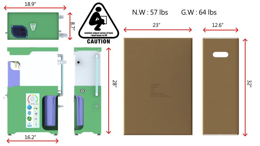

2 Unit Footprint & Layout Description of each component

3 Installation Guide Before starting this installation, carefully unpack and clean all unit elements. For proper part identification and location, it will be most helpful to study the assembly and parts instructions included in this document. Important DO NOT CONNECT TO AN AIR SUPPLY THAT EXCEEDS 145 P.S.I. (10 Bar) Disconnect air supply and depressurize all air lines. After installation, air and coolant systems should be connected and fully tested for proper function and leaks. Please follow the manufacturer s safety guidelines for all power and hand tools used for this installation. Installation of this system on any machine other than those listed, voids any and all intended warranties and liabilities by Green Eco Pro INC. TOOLS REQUIRED: The installation of this unit can be accomplished with basic machine service tools.


4 Installation Guide Page 1 1. Please verify all peripheral accessories. Hose Clamps Oil Reservoir 1 Coolant Return Hose Coolant Inlet Hose Main Unit Filter Wrench Filter Element 2. Installation Instruction Procedure Coolant Float Inlet unit 1.1 Install the filter element - be sure to retain the O-Ring.


5 Installation Guide Page Connect the 1 Coolant Return hose to the Coolant Outlet port using the large hose clamp Connect the Coolant Inlet hose to the Coolant Inlet port using the small hose clamp. 4.1.Connect the Air Supply hose The bracket that holds the float tubes must be attached on the edge of the coolant tank in order to keep it away from the existing chips or debris The Float Tube Inlet must face in the upward position. If there are any suspended solids or floating debris on the surface of the coolant, be sure to remove them before operating the unit In order to keep the Inlet on the surface of coolant, adjust the bracket that retains the float inlet accordingly to an appropriate position. To keep the float tubes balanced, the coolant level must be maintained above 2 if required, please add coolant.


.")
6 Installation Guide Page The above diagrams indicate the position of the Coolant Outlet hose. This is also known as the coolant return hose. Do not jam or bend the hose, gravity will allow the coolant to flow down automatically. The coolant outlet port must be kept above the coolant tank. If required, add a riser block under the leveling support feet. The coolant outlet hose must be kept below the coolant outlet port, as illustrated above Adjust the machine leveling feet, utilizing the leveling gauge. Refer to the diagrams above For the Ultra 360, check the Coolant Volume Adjustment knob. Turn the knob Counter Clockwise (ON).The factory recommended Coolant Volume is to set the pump frequency at 1 pulse per second. Please set at 2 pulses per second if there are any suspended solids in the coolant. Refer to Operation & Safety page 1.


7 Installation Guide Page If the recycled oil exceeds the oil reservoir capacity, you can remove the reservoir and then connect the drain hose to a larger recycle tank. Be sure the oil outlet valve is in the On position In order to obtain the best performance, this coolant purification unit must be installed within 3 Feet from the CNC machine. Once installed, do not remove the unit while in operation.


8 Operation & Safety Page 1 1. Air Pressure & Coolant Volume Adjustment 1.1. After connecting the air supply hose, check the incoming air pressure by reading the gauge. The factory default is set at 35 P.S.I. If the actual air pressure is above/below the factory recommended value, adjust accordingly. The air pressure regulator is located below the oil recycle reservoir. Lowering the air pressure will cause the flow of coolant to stop as well as the pump to not work properly. NOTE: To get a proper reading of air pressure gauge please turn the coolant volume switch On/off then on again The factory recommended coolant volume control is to set the pump frequency at 1 pulse per second In the event of the pump clogging up or if the unit has been sitting idle for a long period of time, this may cause the pump to not function properly. You may have to adjust the air pressure above 35 PSI. Once the pump resumes operation, readjust the air pressure to the factory recommended value of 35 PSI. 2. Relocating the unit 1.1.In case relocation is required, be sure to shut off the oil outlet valve, once it is moved to a desired location please relevel this unit. When foam or bubbles occur in the coolant, please stop the operation of this unit or turn the coolant volume adjustment down.


9 Operation & Safety Page 2 Filter Indicator Under normal condition/operation the filter indicator will read between the Green and Yellow zone. When processing a higher viscosity of way lube oil, the filter indicator may reach the Red zone. Please verify the operation of the float tubes. If the filter indicator stays in red zone, check the condition of float tube hose for obstruction. Please refer to the instructions in the maintenance guide for recovery procedure.


10 Maintenance Guide Page 1 1. Clean the Filter element as illustrated below: 1.1. Be sure to turn off the coolant unit by disconnecting the Air supply hose Use the filter wrench to remove the filter canister, turning the filter as indicated Clean the filter element and the canister by applying high pressure air, as Illustrated above Remove, clean, and reinstall the O-ring 5.1. Reassembly the filter element, the canister, and the O-ring. Install it on the unit. Be sure not to over tighten. Apply appropriate force to lock the filter canister. A missing O-ring will cause the disruption of proper operation. 2. Cleaning the oil and coolant ports Once the filter maintenance is completed, be sure to check all of the coolant and oil ports as well as the float tubes for obstructions. See above illustration


 4. Cleaning the Coolant Reservoir and the S.T.P.M Module 1.")
 to drain any residual coolant. 2. 1.")

11 Maintenance Guide Page 2 3. The location of Oil Lubrication & Filtration 1.1. Check the level of the oil lube on the air regulator unit by removing the side panel. If required, please refill with O.E.M. recommended oil -TURBINE OIL ISO VG When disconnecting the air supply hose, the air regulator will drain some mist automatically. Be sure to check the incoming air supply. The supplied air should be dry and free from contamination Do Not Connect An Air Supply That Exceeds 145 P.S.I. (10 Bar) 4. Cleaning the Coolant Reservoir and the S.T.P.M Module 1. 1.To maintain high performance of the unit, a seasonal maintenance is recommended. Remove the side panel and turn on the valve (see the illustration above) to drain any residual coolant Remove the top cover and loosen the bolt to separate the STPM module. Keep the STPM in one piece and then rinse with clean water or high pressure air to remove dust, once completed, apply the same procedure on coolant reservoir before reinstalling the STPM module. Do not apply any chemical products or water with a temperature that exceeds 194 degrees (F) to STPM module.

12 Faulty Recovery Procedure Page 1 Location of the Pump Reset Button 1. In the event of the pump clogging, temporarily set the air pressure higher and reset the pump. See the illustration above. Once the fault recovery is completed, readjust the air pressure value to recommended value of 35 P.S.I. 2.Lack of oil lubrication may cause the pump to malfunction intermittently. Add the recommended oil, TURBINE OIL ISO VG32, and press the pump reset button.
13 Inspection Sheet - Page 1 Maintenance Check Items Maintenance & Recovery Procedure Weekly Monthly quarterly Clean filter element, canister and Apply high pressure purified air thru or clean it with soap and water O-Ring Filtration System Float Tube hose check Check if cracks or physical damage have occurred Float Tube unit check Check if cracks or physical damage have occurred Check the STPM Module Apply high pressure purified air thru or flush with clean water Air pressure leak check Check air inlet hose if cracks or physical damage have occurred Check pump oil level Add oil if needed. Recommended Oil : TURBINE OIL ISO VG32 Pneumatic & Coolant Air filtration system Check if there is water in the reservoir bowl Circulating System Check connecting hoses Check coolant inlet hose, coolant return hose, and floatation inlet hose for cracking/leaking or deterioration. Check Air pressure gauge Readjust air pressure to 35 P.S.I.


14 Inspection Sheet - Page 2 Maintenance Check Items Maintain & Recovery Procedure Weekly Monthly Quarterly 1.Check unit exterior Clean the exterior of the unit with towel Unit interior & exterior 2. Check the window glass Clean with towel 3 Oil recycling reservoir clean with towel, replacement is required if cracks occurred
15 WARRANTY STATEMENT Terms & Conditions In the event that a fault occurs with the machine or any parts supplied with it due to workmanship or defective materials, Green Eco Pro will replace any faulty components (other than consumable components) for a period of 12 months from the date of installation. Provided the following: 1. You have notified us of the relevant fault within 7 days of discovering it. 2. The machine has been used in accordance with our instructions. 3. The fault is not due to reasonable wear and tear and does not relate to consumable components (including, without limitation, filters, filter element, hand tool, O-ring). 4. Should the machine require relocation, make sure that the oil outlet valve is in the Off position. Relocate and level the unit. Otherwise, while cycling, the coolant purification unit shall not be moved. 5. We shall be entitled to have returned any components replaced by us under this warranty. 6. The warranty shall be deemed void if the customer or a third party modifies or repairs the equipment without having Green Eco Pro s previous approval. The warranty offered on these products provides coverage against defective parts or faulty workmanship subjected to all routine maintenance and run up procedures being observed and carried out within these periods as detailed by Green Eco Pro Co. The warranty does not cover for replacements in the event of accidental such as natural disasters or malicious damage or damage caused by misuse of the product. Part Warranty With the exception of easily worn parts mentioned above, all other repair parts, when replaced, shall have a 6 month factory warranty period on the part itself regardless of the machine warranty term.
16 Part List-1(B.O.M)
17 Part List-2(B.O.M)
18 Part List-3(B.O.M) Part Number Description Qty/per unit RA2-001 Top Cover 1 RA2-002 Upper main unit 1 RA2-003 Lower main unit 1 RA2-004 Side panel 1 RA2-005 Window panel 1 RA2-006 Oil recycle reservoir 1 A001 Filter canister inlet 1 A micron filter element 1 A003 O Ring 1 A004 Filter Canister 1 A005 Filter Wrench 1 A006 Pump 1 A007 Air regulator 1 A008 Reduction valve- 1/4 1 A009 STPM Module 1 A010 Filter indicator 1 B001 Float tubes 3 B002 Multi directional connector 1 B003 Float tube inlet 1 B004 Float tube support bracket 1 RA2-D Screws set 1 B005 Magnet 1 B006 Float tube inlet hose -8*12 1 C001 Straight fitting -1*1 1 C003 Straight fitting-1/2*1/2 2 C degree fitting-1/2*1/2 3 C005 Straight fitting -3/8*1/2 2 C006 Control valve-1/2*1/2 2 C007 Straight threaded fitting 1 C008 Quick disconnect fitting - 1/4 1 C011 Hose clamp-3/4 1 C012 Hose Clamp- 1 1/4 1 C013 Coolant hose-1/2 3 C014 Coolant hose-1 1 C015 Air hose 8MM 3 C016 PUMP support legs 4 C017 Adjustable leveling support 4 C018 Gasket 1 C019 T style fitting 1 C020 Bubble Leveling gauge 1
Coolant Purification Systems Ultra 360 INSTRUCTION MANUAL
 Coolant Purification Systems Ultra 360 INSTRUCTION MANUAL Model: Ultra 360 Serial No. Manufacture Date: Revision: M Unit Footprint & Layout Description of each component Installation Guide Before starting
Coolant Purification Systems Ultra 90 INSTRUCTION MANUAL
 Coolant Purification Systems Ultra 90 INSTRUCTION MANUAL Model: Ultra 90 Serial No. Manufacture Date: Revision: E September 2016 Unit Foot Print & Layout Description of each components Installation Guide
Chip Vacuum Removal System INSTRUCTION MANUAL
 Chip Vacuum Removal System INSTRUCTION MANUAL GREEN ECO PRO Co.,Ltd. e-mail:service@rwwa.com.tw 427 Model: Serial No. Manufacture Date: FC Version : SM December 2017 FC-SERIES Dimension & Carton FC-180
MASTER COALESCER JR & PORTABLE MASTER COALESCER JR AIR PUMP MODEL INSTALLATION MANUAL
 MASTER COALESCER JR & PORTABLE MASTER COALESCER JR AIR PUMP MODEL INSTALLATION MANUAL INSTALLATION: CHOOSING THE LOCATION: Locate the coalescer as near to the intended point of use as possible. Avoid high
Maintenance Manual. Automated. Fuel Maintenance System FTI-5A. FUEL TECHNOLOGIES INTERNATIONAL LLC
 Maintenance Manual Automated Fuel Maintenance System FTI-5A FUEL TECHNOLOGIES INTERNATIONAL LLC www.fueltechnologiesinternational.com 03/01/2011 - Fuel Technologies FTI-5A Maintenance Section FTI - Fuel
Maintenance Manual WITH ONE SUBMERSIBLE PUMP. Automated Fuel Maintenance System FTI-5A FUEL TECHNOLOGIES INTERNATIONAL LLC
 Maintenance Manual WITH ONE SUBMERSIBLE PUMP Automated Fuel Maintenance System FTI-5A FUEL TECHNOLOGIES INTERNATIONAL LLC Replacement Manuals Available on Website: www.fueltechnologiesinternational.com
XP-115 Multi-Port Power Pack Operation and Maintenance Manual
 XP-115 Multi-Port Power Pack Operation and Maintenance Manual http://www.torsionx.com Safety Guide To use the XP-115 Multi-Port Power Pack safely you must follow correct operation guidelines and inspect
XP-AIR Multi-Port Power Pack Operation and Maintenance Manual
 XP-AIR Multi-Port Power Pack Operation and Maintenance Manual http://www.torsionx.com Safety Guide To use the XP-AIR Multi-Port Power Pack safely you must follow correct operation guidelines and inspect
FPU SYSTEMS OPERATION MANUAL (INCLUDING REPAIR PARTS & SPECIAL TOOL LIST) BOH CONTAINERIZED LATRINES BOH FPU Field Pack-up Units
 BOH CONTAINERIZED LATRINES BOH FPU Field Pack-up Units") FPU SYSTEMS OPERATION MANUAL (INCLUDING REPAIR PARTS & SPECIAL TOOL LIST) BOH CONTAINERIZED LATRINES BOH FPU Field Pack-up Units CHAPTER 4 OPERATOR MAINTENANCE INSTRUCTIONS 2016 BOH Environmental LLC This
FPU SYSTEMS OPERATION MANUAL (INCLUDING REPAIR PARTS & SPECIAL TOOL LIST) BOH CONTAINERIZED LATRINES BOH FPU Field Pack-up Units CHAPTER 4 OPERATOR MAINTENANCE INSTRUCTIONS 2016 BOH Environmental LLC This
Maintenance Manual. Automated Fuel Maintenance System FTI-5A SINGLE TANK FUEL TECHNOLOGIES INTERNATIONAL
 Maintenance Manual Automated Fuel Maintenance System FTI-5A SINGLE TANK FUEL TECHNOLOGIES INTERNATIONAL 05/01/2016 Rev A Fuel Technologies FTI-5A Single Tank Maintenance Section FTI - Fuel Maintenance
TWO-STAGE HYDRAULIC PUMP. RWP55-IBT-Air
 ORIGINAL INSTRUCTIONS Form No.1000458 5 SPX Corporation 5885 11th Street Rockford, IL 61109-3699 USA Tech. Services: (800) 477-8326 Fax: (800) 765-8326 Order Entry: (800) 541-1418 Fax: (800) 288-7031 Internet
Hydraulic and Commissioning Mannual Module 2A
 Hydraulic and Commissioning Mannual Module 2A 2/7 Table of Contents 1 Features 3 2 Hydraulic Commissioning 3 2.1 Functional Purpose 3 2.2 System Description 3 3 Hydraulic Commissioning Instructions 4 4
INSTALLATION and OPERATION BALL WASHER MODEL NO: BW-001N
 Easy Picker Golf Products, Inc. 415 Leonard Blvd. N., Lehigh Acres, FL 33971 PH: 239-368-6600 FAX: 239-369-1579 Service: 800-982-4653 SALES: 800-641-4653 www.easypicker.com salesdept@easypicker.com INSTALLATION
KLW4000D Multi-Port Power Pack
 KLW4000D Multi-Port Power Pack Operation and Maintenance Manual Safety Guide To use the KLW4000DMulti-Port Power Pack safely you must follow correct operation guidelines and inspect the equipment regularly.
ZTM AND ZTMB ZENNER TURBINE METERS INSTALLATION, MAINTENANCE AND SERVICING
 ZTM AND ZTMB ZENNER TURBINE METERS INSTALLATION, MAINTENANCE AND SERVICING INSTALLATION 1. The meter is intended for measuring potable, cold water in one direction. 2. The meter is to be installed in a
300 Series INSTRUCTION MANUAL. Compressed Air Filters Models 302 (grade) through 317 (grade)
 through 317 (grade)") INSTRUCTION MANUAL 300 Series Compressed Air Filters Models 302 (grade) through 317 (grade) FORM NO.: 3259480 REVISION: 01/2014 READ AND UNDERSTAND THIS MANUAL PRIOR TO OPERATING OR SERVICING THIS PRODUCT.
INSTRUCTION MANUAL 300 Series Compressed Air Filters Models 302 (grade) through 317 (grade) FORM NO.: 3259480 REVISION: 01/2014 READ AND UNDERSTAND THIS MANUAL PRIOR TO OPERATING OR SERVICING THIS PRODUCT.
LIQUID LEVEL FLOAT SWITCH. F7 Series INSTALLATION AND OPERATIONS MANUAL. Single-Point, Vertically-Mounted Liquid Level Float Switch
 F7 Series LIQUID LEVEL FLOAT SWITCH INSTALLATION AND OPERATIONS MANUAL Single-Point, Vertically-Mounted Liquid Level Float Switch F7 Series LIQUID LEVEL FLOAT SWITCH Single-Point, Vertical Mount 1.0 Installation
INSTALLATION and OPERATION BALL DISPENSER MODEL NOS: BD-001AN, -002, -003AN, -004, -010AN, -011
 Easy Picker Golf Products, Inc. 415 Leonard Blvd. N., Lehigh Acres, FL 33971 PH: 239-368-6600 FAX: 239-369-1579 Service: 800-982-4653 SALES: 800-641-4653 www.easypicker.com salesdept@easypicker.com INSTALLATION
HP COOL TECH, INC. COOLANT PUMP. PowerPump. OPREATIONS MANUAL Series 10000/11000
 HP COOL TECH, INC. COOLANT PUMP PowerPump OPREATIONS MANUAL Series 10000/11000 1 TABLE OF CONTENTS Page Topic 3 Introduction 3 Specifications 3 Warning 4 Safety 5 Use 6 Filter Replacement Procedure 7 Operator
Low Profile J Series Power Unit with Vane Pump
 Low Profile J Series Power Unit with Vane Pump READ ALL INSTRUCTIONS CAREFULLY BEFORE ATTEMPTING TO ASSEMBLE, INSTALL, OPERATE OR MAINTAIN THE PRODUCT DESCRIBED. PROTECT YOURSELF AND OTHERS BY OBSERVING
INSTALLATION and OPERATION BALL DISPENSER MODEL NOS: BD-001 THRU BD-004, BD-010, BD-011
 Easy Picker Golf Products, Inc. 415 Leonard Blvd. N., Lehigh Acres, FL 33971 PH: 239-368-6600 FAX: 239-369-1579 Service: 800-982-4653 SALES: 800-641-4653 www.easypicker.com salesdept@easypicker.com INSTALLATION
Q= C. v P S Refer to Table 1 for part numbers and shipping weights. Accessories: Table 1: Valve Part Numbers and Specifications
 1 of 9 1. DESCRIPTION The Viking Flow Control Valve is a quick opening, differential diaphragm flood valve with a spring loaded floating clapper. The Flow Control Valve can be used to facilitate manual
CENTRAL SLURRY SYSTEMS Model 911
 CENTRAL SLURRY SYSTEMS Model 911 Installation and Operating Instructions Revised 6/04/08 PRACTICAL SYSTEMS, INC. 11617 Prospect Road Odessa, FL 33556 (800) 237-8154 Fax (800) 330-3800 (727) 376-7900 Fax
SYSTEM SAVER 318 AIR COMPRESSOR FOR MACK E-TECH AND ASET ENGINES MAINTENANCE MANUAL
 SYSTEM SAVER 318 AIR COMPRESSOR FOR MACK E-TECH AND ASET ENGINES MAINTENANCE MANUAL NON-THROUGH DRIVE THROUGH DRIVE Service Notes About This Manual This manual provides service and repair procedures for
ACF Operation Manual
 ACF-3000 Operation Manual MAHLE Aftermarket Inc., RTI Division 10 Innovation Drive York, Pennsylvania 17402 USA Phone: 717-840-0678 Toll Free: 800-468-2321 Web-site: www.rtitech.com Manual P/N: 035 81825
Models: 8500, 8501, 8513, 8514, 8500BL, 8501BL, 8513BL, 8514BL, 8540, 8541, 8550, 8551, 8540BL, 8541BL, 8550BL & 8551BL
 Standard Pump Ultra Mass High Viscosity Batch Control System Description Standard s Drum Pumps are designed to transfer a variety of materials from 55 gallon drums and tanks. Standard Pump offers several
Installation and Maintenance Guide SF1593 SF1594 B/E ELECTRONIC LAVATORY FAUCET
 Installation and Maintenance Guide SF1593 SF1594 B/E ELECTRONIC LAVATORY FAUCET 1 INDEX 1 TECHNICAL DATA 2 PACK CONTENTS 3 PRE INSTALLATION INFORMATION 4-5 FAUCET INSTALLATION 6-8 SETTINGS ADJUSTMENT 9
Purging Air From Divider Block Lubrication Systems
 FROST ENGINEERING SERVICE Purging Air From Lubrication Systems A D I V I S I O N O F G E C S E Y S A L E S & S E R V I C E DESCRIPTION Divider block lubrication systems operate correctly only when all
Innoquest Item # Product Manual
 Innoquest Item # 29480 Product Manual Table of Contents 1.0 Safety Information. 2 2.0 Introduction... 3 2.1 Spray Case Diagram. 3 2.2 Features 4 3.0 Specifications. 5 4.0 Set-up & Operation... 6 4.1 Charging
PENSKE SHOP PRO FXP TECHNICAL MANUAL. FOR ADDITIONAL INFORMATION, VISIT TABLE OF CONTENTS
 PENSKE SHOP PRO FXP TABLE OF CONTENTS Applications and Features...1 Shop Pro FXP Components...2 EEImportant Safety Precautions.... 3 Set-up and Maintenance...4 Hoses and Adapters....5 Hose Connections
PE 20 SERIES ELECTRIC POWER PUMPS
 A Division Of Templeton, Kenly & Co., Inc. PE 20 SERIES ELECTRIC POWER PUMPS Operating Instructions Manual For 1/2 hp, 115 Volt and 230 Volt PEM, PPM, PES and PPS Models Revison B 07/2006 2525 Gardner
Operating Instructions - Electric Pow'r-Riser Models
 ADivisionOf Templeton, Kenly& Co., Inc. Operating Instructions - Electric Pow'r-Riser Models Table of Contents 1.0 Recieving Instructions 2.0 Safety 3.0 Specifications 4.0 Initial Installation Before Operating
INSTALLATION and OPERATION INSTRUCTIONS
 Part Numbers: 54580 and 54580-2 Part Number 54580 Shown OUT IN INSTALLATION and OPERATION INSTRUCTIONS TABLE OF CONTENTS Section Page Warranty.... 2 General Information.... 3 Introduction..... 3 System
Pneumatic High-Viscosity Filtration System Instruction Manual
 Pneumatic High-Viscosity Filtration System Instruction Manual P/N: 61512 05/17 1 2 Pneumatic High Viscosity Filtration Systems PN: 61512 14 April, 2009 rev A 36933 Pneumatic Hand Cart HV Filtration System
SHOP PRO ST TECHNICAL MANUAL. FOR ADDITIONAL INFORMATION, VISIT TABLE OF CONTENTS
 SHOP PRO ST TABLE OF CONTENTS Applications and Features...1 Shop Pro ST Components...2 EEImportant Safety Precautions.... 3 Set-up and Maintenance...4 Hoses and Adapters....5 Hose Connections for Priming...6
CENTRAL SLURRY SYSTEMS Model 915
 CENTRAL SLURRY SYSTEMS Model 915 Installation and Operating Instructions 08/02/18 PRACTICAL SYSTEMS, INC. 11617 Prospect Road Odessa, FL 33556 (800) 237-8154 Fax (800) 330-3800 (727) 376-7900 Fax (727)
PENSKE SHOP PRO ST WITH 50/80 PSI REGULATOR TECHNICAL MANUAL. FOR ADDITIONAL INFORMATION, VISIT TABLE OF CONTENTS
 TABLE OF CONTENTS Applications and Features...1 Shop Pro ST Components...2 EEImportant Safety Precautions.... 3 Set-up and Maintenance...4 Hoses and Adapters....5 Hose Connections for Removing Fuel.............................
CRD610 Automatic Fitting Inserter
 CRD610 Automatic Fitting Inserter OPERATIONS MANUAL VERSION 1.2 LAST EDITED 12.12.2018 cleanroomdevices.com 1 Table of Contents Title Page. 1 Table of Contents...2 1.0 General Product & Safety Information....3
FBC CODES AND TRANSLATIONS TRANSLATION
 FBC CODES AND TRANSLATIONS CODE TRANSLATION 500 air cleaning system checked 501 air cleaner housing found cracked 502 repaired cracked air cleaner housing 503 renewed air cleaner housing 504 air intake
MicroCoat System Operating Manual MC4000 Series MC785M, MC785M-WF Spray Valves
 MicroCoat System Operating Manual MC Series MC785M, MC785M-WF Spray Valves A NORDSON COMPANY Introduction The MicroCoat System provides precise lubrication control for metal stamping operations. The MC
OWNER S MANUAL EVOLUTION 3500, 4500, 5500, & 8500 SERIES PUMPS
 OWNER S MANUAL EVOLUTION 3500, 4500, 5500, & 8500 SERIES PUMPS IMPORTANT SAFETY INSTRUCTIONS When installing and using this electrical equipment, basic safety precautions should always be followed, including
Manual Concentrate Management System
 Form 887 05/15 Manual Concentrate Management System with Automatic Flush INSTALLATION AND OPERATION MANUAL Unit Serial Number All quality FoamPro products are ruggedly designed, accurately machined, carefully
FAN POWERED HEPA FILTER UNIT
 READ COMPLETELY AND SAVE THESE INSTRUCTIONS FOR FUTURE REFERENCE FAN POWERED HEPA FILTER UNIT (MOTOR ACCESSIBLE) SSLFHFD-FP-MA INSTALLATION AND SERVICE MANUAL 2 Critical operation conditions of the Fan
Scale Feeder Manifold Water Filtration System Instruction Manual
 3M TM Water Filtration Products Scale Feeder Manifold Water Filtration System Instruction Manual For SF1XX High Flow Series Water Filtration Systems Installer: Please leave this manual with owner/operator.
CRD600 Automatic Fitting Inserter
 CRD600 Automatic Fitting Inserter OPERATIONS MANUAL VERSION 2.3 LAST EDITED 12.07.2018 cleanroomdevices.com 1 Table of Contents Title Page.. 1 Table of Contents. 2 1.0 General Product & Safety Information...3
CLEAN ROOM DEVICES, LLC "WHERE TUBING AND FITTINGS COME TOGETHER"
 CLEAN ROOM DEVICES, LLC "WHERE TUBING AND FITTINGS COME TOGETHER" CRD600 Automatic Fitting Inserter OPERATIONS MANUAL VERSION 2.1 LAST EDITED 7.25.14 DOCUMENT NUMBER 001 cleanroomdevices.com 1 Table of
CLEAN ROOM DEVICES, LLC "WHERE TUBING AND FITTINGS COME TOGETHER"
 CLEAN ROOM DEVICES, LLC "WHERE TUBING AND FITTINGS COME TOGETHER" CRD600AF Automatic Fitting Inserter With Auto Feed OPERATIONS MANUAL (Shown with optional alcohol dispenser) 1 VERSION 1.1 LAST EDITED
SECTION 4 - FUEL/LUBRICATION/COOLING
 For Arctic Cat Discount Parts Call 606-678-9623 or 606-561-4983 SECTION 4 - FUEL/LUBRICATION/COOLING 4 TABLE OF CONTENTS Carburetor Specifications... 4-2 Carburetor Schematic... 4-2 Carburetor... 4-3 Cleaning
PNEUMATICS CONTENTS HST-TAMPER
 CONTENTS Tamper Pneumatic Component Locations...2 Manually Releasing Air Brakes... 3 Releasing Air Pressure... 4 Removing Water from Air Tanks... 4 Adjusting Air Compressor Governor... 4 Check/Replace
AEROMOTIVE Part # and F-Body Fuel System Kit INSTALLATION INSTRUCTIONS
 AEROMOTIVE Part # 17101 and 17102 93-97 F-Body Fuel System Kit INSTALLATION INSTRUCTIONS CAUTION: Installation of this product requires detailed knowledge of automotive systems and repair procedures. We
SHOP PRO FXP TECHNICAL MANUAL. FOR ADDITIONAL INFORMATION, VISIT TABLE OF CONTENTS
 SHOP PRO FXP TABLE OF CONTENTS Applications and Features...1 Shop Pro FXP Components...2 EEImportant Safety Precautions.... 3 Set-up and Maintenance...4 Hoses and Adapters....5 Hose Connections for Priming...6
SHOP PRO FXP 95 TECHNICAL MANUAL
 SHOP PRO FXP 95 TABLE OF CONTENTS Applications and Features... 1 Shop Pro FXP 95 Components... 2 Important Safety Precautions.... 3 Set-up and Maintenance... 4 Prevent Fuel Spillage... 5 Hoses and Adapters...
Table 6-1. Problems and solutions with pump operations. No Fluid Delivery
 Table 6-1. and solutions with pump operations No Fluid Delivery Fluid level in the reservoir is low. Oil intake pipe or inlet filter is plugged. Air leak in the inlet line prevents priming or causes noise
 CARCO ES-370 AKT Spray Gun The ES-370 AKT Automatic Spray Gun is a production spray gun designed to apply a wide range of marking fluids, including Carco pigmented and dye type marking fluids. CONNECTIONS:
INSTALLATION AND MAINTENANCE GUIDE SF1596 B/E ELECTRONIC LAVATORY FAUCET
 INSTALLATION AND MAINTENANCE GUIDE SF1596 B/E ELECTRONIC LAVATORY FAUCET 1 INDEX 1 TECHNICAL DATA 2 PACK CONTENTS 3 PRE-INSTALLATION INFO 4-5 INSTALLATION 6-8 SETTINGS ADJUSTMENT WITH REMOTE CONTROL 9
PHANTOM (PH10 and PH12) COMMERCIAL AND INDUSTRIAL SERIES
 COMMERCIAL AND INDUSTRIAL SERIES") Document No: ICM-IOM Date: 0411 PHANTOM (PH10 and PH12) COMMERCIAL AND INDUSTRIAL SERIES Installation, Operation and Maintenance Manual Please read and save these instructions. Read carefully before attempting
Document No: ICM-IOM Date: 0411 PHANTOM (PH10 and PH12) COMMERCIAL AND INDUSTRIAL SERIES Installation, Operation and Maintenance Manual Please read and save these instructions. Read carefully before attempting
15,000kg HYDRAULIC BOTTLE JACK
 Product Code: 2013 OWNER S MANUAL PRODUCT CODE: 2013 15,000kg HYDRAULIC BOTTLE JACK Lifting Capacity 15,000kg Max. Lifting Height 447mm Min. Lifting Height 227mm Hydraulic Lift 125mm Screw Adjustment 70mm
L007 LIQUID LEVEL FLOAT SWITCH. Side-Mounted Liquid Level Float Switch INSTALLATION AND OPERATIONS MANUAL
 L007 LIQUID LEVEL FLOAT SWITCH INSTALLATION AND OPERATIONS MANUAL Side-Mounted Liquid Level Float Switch READ THIS MANUAL PRIOR TO INSTALLATION This manual provides information on the L007 Side- Mounted
Operating instructions Form no safety definitions
 Operating instructions Form no. 1000437 safety definitions safety symbols are used to identify any action or lack of action that can cause personal injury. Your reading and understanding of these safety
HTC-1200 Recirculating Heater. NESLAB Manual P/N Rev. 04/22/98. Operation and Maintenance Manual
 HTC-1200 Recirculating Heater NESLAB Manual P/N 013966 Rev. 04/22/98 Operation and Maintenance Manual HTC-1200 Recirculating Heater Operation and Maintenance Manual PREFACE SECTION I Safety SECTION II
Where to Find Us. Pressure Washer. Model Number Revision Serial Number. Date Purchased
 Thank you for purchasing this quality-built Troy-Bilt pressure washer. We are pleased that you ve placed your confidence in the Troy-Bilt brand. When operated and maintained according to the instructions
Premium Supply. Direct Push. Models PCK-3530-DP PCK DP PCK-530-DP. Operator s Manual and Installation Instructions
 Direct Push Models PCK-3530-DP PCK-3530-2DP PCK-530-DP Operator s Manual and Installation Instructions Premium Supply 2038 West Interstate 30 866-934-0777 Proud members of: and June 20, 2018 Table of Contents
MicroCoat. System Operating Manual MC2000 Series. MC785, MC785-WF Spray Valves. US: UK: Mexico:
 MicroCoat System Operating Manual MC2 Series MC785, MC785-WF Spray Valves A NORDSON COMPANY US: 8-498-8865 UK: 8 585733 Mexico: 1-8-556-3484 Introduction The MicroCoat System provides precise lubrication
FUEL SYSTEM. Table of Contents. Specifications. Section 3A Fuel Delivery System. Models 6/8/9.9/10/15 CARBURETOR SPECIFICATIONS
 FUEL SYSTEM Section 3A Fuel Delivery System Table of Contents Specifications............................. 3A-1 WMC Carburetor Specifications............. 3A-2 WMC Carburetor Specifications.............
KEEP FOR FUTURE REFERENCE DC VACUUM BACK-UP SYSTEM READ ALL INSTRUCTIONS AND WARNINGS BEFORE USING THIS PRODUCT
 KEEP FOR FUTURE REFERENCE P.O. Box 368 908 West Main Laurel, MT USA 59044 phone 800-548-7341 phone 406-628-8231 fax 406-628-8354 INSTRUCTIONS International Version STOCK NUMBERS: SEE SPECIFICATIONS DC
Operation & Maintenance Manual. Sludge Vac. Visit our Website for more information on this product.
 DIVERSITECH Operation & Maintenance Manual Sludge Vac Visit our Website for more information on this product www.diversitech.ca 2500 Alphonse Gariepy, Montreal, Quebec H8T 3M2 Tel: 1.800.361.3733 Fax:
5. FUEL SYSTEM FUEL SYSTEM 5-0
 5 FUEL SYSTEM 5-0 SERVICE INFORMATION GENERAL INSTRUCTIONS SERVICE INFORMATION...5-1 CARBURETOR INSTALLATION...5-9 TROUBLESHOOTING...5-1 PILOT SCREW ADJUSTMENT...5-10 CARBURETOR REMOVAL...5-2 AUTO BYSTARTER...5-3
L-Series: LIQUID LEVEL FLOAT SWITCH. Single-Point, Vertically-Mounted Liquid Level Float Switch INSTALLATION AND OPERATIONS MANUAL
 L-Series: L001, L002, L003, L170, L175, L176, L177, L178, L180, L190 AND L195 LIQUID LEVEL FLOAT SWITCH INSTALLATION AND OPERATIONS MANUAL Single-Point, Vertically-Mounted Liquid Level Float Switch L001
¼ to 1HP Chiller Service Manual
 ¼ to 1HP Chiller Service Manual Before performing any service to the unit, reset the controller to its default settings. It is our experience that many problems can be resolved by doing so. See Sec. 3.1
WARNING DYNABRADE. Air Powered Abrasive Belt Machine
 For Serial No.9I1001 and Higher Parts Page Reorder No. PD00 50 Effective June, 2000 Supercedes PD96 16 66402 Tool Post Grinder Instruction Manual Air Powered Abrasive Belt Machine! WARNING Always operate,
EZ FILL FAUCET AUTOMATIC DECK MOUNTED FAUCET INSTALLATION AND MAINTENANCE GUIDE
 EZ FILL FAUCET AUTOMATIC DECK MOUNTED FAUCET INSTALLATION AND MAINTENANCE GUIDE 05 September 018 TABLE OF CONTENTS PRE-INSTALLATION INFORMATION PRE-INSTALLATION INFORMATION 3 PACK CONTENTS 4 TECHNICAL
AEROMOTIVE Part # Mustang 5.0L Fuel System Kit INSTALLATION INSTRUCTIONS
 AEROMOTIVE Part # 17103 83-93 Mustang 5.0L Fuel System Kit INSTALLATION INSTRUCTIONS CAUTION: Installation of this product requires detailed knowledge of automotive systems and repair procedures. We recommend
4400 Airless Product Manual
 4400 Airless Product Manual TABLE OF CONTENTS Precautionary Warning... Page 1 Assembly... Page 2 Operation... Page 3 Spray Tip Cleaning... Page 4 Cleaning Procedure... Page 4 Cleaning Procedure... Page
D28 SERIES WALL MOUNTED ELECTRONIC FAUCET FOR COLD OR PREMIXED WATER. D28 B D28 E D28 Dual Power B D28 Dual Power E D28 Box D28 Box E
 D28 SERIES WALL MOUNTED ELECTRONIC FAUCET FOR COLD OR PREMIXED WATER D28 B D28 E D28 Dual Power B D28 Dual Power E D28 Box D28 Box E 1 INDEX 1 TECHNICAL DATA 2-4 PACK CONTENTS 5 PRE-INSTALLATION INFO 6-11
THE SSD CHUTE IS INTENDED FOR THE DESTRUCTION OF SOLID STATE MEDIA ONLY! ATTEMPTING TO SHRED ROTATIONAL DRIVES WILL VOID WARRANTY!
 Security Engineered Machinery Model 0304 Comboo SSD/HDD Shredder OPERATION AND MAINTENANCE MANUAL POP 0065 Rev. 1 Revised: 10/21/2016 Security Engineered Machinery Co., Inc E Mail: Service@SEMSHRED.com
USER S GUIDE FOR AUTO TRANSMISSION FLUID
 USER S GUIDE FOR AUTO TRANSMISSION FLUID HO-211 This manual was prepared in November, 2002. The product specifications contained in this manual are subject to change without prior notice. Contents Chapter
WCI-20 Power-Pak Coldwork Hydraulic Power Supply Rev B
 WCI-20 Power-Pak Coldwork Hydraulic Power Supply Rev B OM-PS-9303-2 Seattle, Washington WCI-20 Power Pak Manual Table of Contents Section 1 Introduction 1.1 Introduction... 1 1.2 Safety Precautions...
As a safety precaution, remove keys from the ignition while working under or around the vehicle.
 CAB AND CHASSIS As a safety precaution, remove keys from the ignition while working under or around the vehicle. 1. Approach Check the overall appearance of vehicle stance (not leaning). Check for signs
High Performance Vacuum Pump Model 15120A/15121A Operating Manual...
 High Performance Vacuum Pump Model 15120A/15121A Operating Manual... Operating Manual Table of Contents Warnings...1 CoolTech high performance vacuum pumps...1 Pump components...2 Before using your vacuum
SPECIFICATIONS: Tank Size: 80 gallons PUMP RPMs: 1050 CFM: 40PSI; 90 PSI Max Pressure: 150 PSI Thermal overload protection
 5HP 80 GALLON TWO STAGE COMPRESSOR Models: 51866, 51870 CALIFORNIA PROPOSITION 65 WARNING: You can create dust when you cut, sand, drill or grind materials such as wood, paint, metal, concrete, cement,
STYLE 5148 MERCURYMASTER OSCILLATING NOZZLE INSTALLATION, OPERATING, AND MAINTENANCE INSTRUCTIONS
 STYLE 5148 MERCURYMASTER OSCILLATING NOZZLE INSTALLATION, OPERATING, AND MAINTENANCE INSTRUCTIONS The following is intended to provide the basic instructions for installation, operation, and maintenance.
Crispin Valves Operating Guide. Crispin
 Crispin Valves Operating Guide Crispin Since 1905 Crispin Multiplex Manufacturing Co. 600 Fowler Avenue Berwick, PA 18603 1-800-AIR-VALV T: (570) 752-4524 F: (570) 752-4962 www.crispinvalve.com sales@crispinvalve.com
MAINTENANCE MANUAL FOR THERMOSTATIC TEMPERATURE REGULATING VALVE TRAC STYLE P
 MANUAL NUMBER P-EFS-1 MAINTENANCE MANUAL FOR THERMOSTATIC TEMPERATURE REGULATING VALVE TRAC STYLE P TRAC Regulator Company Inc. 160 South Terrace Avenue Mount Vernon, New York USA 10550-2408 Phone: (914)
or OWNER S MANUAL MODEL R
 www.superiorwaterandair.com 801-974-9090 or 800-974-7638 OWNER S MANUAL MODEL 48-1000R Table of Contents Introduction...Page 1 Flow Diagrams...Page 3 The Electro-mechanical Timer Programming...Page 4 Extra
GROUP 13C 13C-1 CONTENTS GENERAL DESCRIPTION... 13C-2 FUEL TANK... 13C-11 FUEL SUPPLY DIAGNOSIS... 13C-3 SPECIAL TOOLS... 13C-8
 13C-1 GROUP 13C CONTENTS GENERAL DESCRIPTION......... 13C-2 DIAGNOSIS....... 13C-3 INTRODUCTION TO DIAGNOSIS........................ 13C-3 TROUBOLESHOOTING STRATEGY..... 13C-3 SYMPTOM CHART...................
CONTENTS. EMERGENCY PUMP USE Electric Pump...H-3 Manual Pump...H-5
 Anchor Applicator Model BAAM HYDRAULIC CONTENTS EMERGENCY PUMP USE Electric Pump...H-3 Manual Pump...H-5 PRESSURE SETTINGS General Settings and Locations of Manifolds...H-5 Main System Pressure and Relief...H-6
36-1 DP PLEASE READ BEFORE USING THIS EQUIPMENT
 36-1 DP PLEASE READ BEFORE USING THIS EQUIPMENT DP 36-1 Assembly Instructions PLEASE READ INSTRUCTIONS COMPLETELY BEFORE STARTING We thank you for purchasing the DP-36 pressure system. This system has
UNPACKING SAFETY GUIDELINES GENERAL SAFETY INFORMATION. Operating Instructions & Maintenance Manual
 Please read and save this Repair Parts Manual. Read this manual and the General Operating Instructions carefully before attempting to assemble, install, operate or maintain the product described. Protect
OWNER S MANUAL. Model: FSUTV-45-12V ( ) (45 Gallon Lawn & Garden UTV Sprayer, Boom Ready) Technical Specifications. Assembly Instructions
 (45 Gallon Lawn & Garden UTV Sprayer, Boom Ready) Technical Specifications. Assembly Instructions") OWNER S MANUAL Model: FSUTV-45-12V (5302903) (45 Gallon Lawn & Garden UTV Sprayer, Boom Ready) Technical Specifications 45 Gal. Corrosion-Resistant Polyethylene Tank Deluxe Pistol-Grip Handgun 25 Ft. Handgun
OWNER S MANUAL Model: FSUTV-45-12V (5302903) (45 Gallon Lawn & Garden UTV Sprayer, Boom Ready) Technical Specifications 45 Gal. Corrosion-Resistant Polyethylene Tank Deluxe Pistol-Grip Handgun 25 Ft. Handgun
INSTALLATION & SERVICE INSTRUCTION MANUAL W.A. KATES FLOW CONTROLLERS FC VALVE MODELS E THRU M
 INSTALLATION & SERVICE INSTRUCTION MANUAL W.A. KATES FLOW CONTROLLERS FC VALVE MODELS E THRU M IMPORTANT 1. W. A. Kates flow rate controllers are designed to accurately regulate flows and are precision
Operating Instructions and Parts Manual AHR-50 Auto Rewind Hose Reel
 Operating Instructions and Parts Manual AHR-50 Auto Rewind Hose Reel JET 427 New Sanford Road LaVergne, Tennessee 37086 Part No. M-426238 Ph.: 800-274-6848 Revision C 04/2017 www.jettools.com Copyright
Tests & Adjustments - General Machine. General Safety Hydraulic Tank Turbo Boost Regulator
 Section 8.1 Tests & Adjustments - General Machine General Safety......................................... 8.1.2 Hydraulic Tank Turbo Boost Regulator........................ 8.1.2 Hydraulic Tank Safety
OPERATION AND PARTS MANUAL
 OPERATION AND PARTS MANUAL MODEL NUMBER : PART NUMBER : TAP- IN KIT 5100-5151 BAYNE MACHINE WORKS, INC. PHONE: (864) 288-3877 910 FORK SHOALS ROAD TOLL FREE: (800) 535-2671 GREENVILLE S.C., 29605 FAX:
HL Series Inline Lever Start Auto Shut Off SEE LAST PAGE FOR IMPORTANT INFORMATION
 HL Series Inline Lever Start Auto Shut Off SEE LAST PAGE FOR IMPORTANT INFORMATION May 2016 Pneumatic Screwdriver Product Description A Pneumatic Screwdriver, or nut runner is a compressed air powered
GBP784B INSTALLATION TOOL
 GBP784B INSTALLATION TOOL GAGE BILT MADE IN U.S.A. GAGE BILT PRODUCTS CORP. 14500 Barber Drive (586) 771-7664 Warren, Mi 48088 (586) 771-2665 Fax e-mail:solutions@gagebilt.com / www.gagebilt.com TABLE
UNPACKING SAFETY GUIDELINES GENERAL SAFETY INFORMATION. Operating Instructions & Maintenance Manual
 Please read and save this Repair Parts Manual. Read this manual and the General Operating Instructions carefully before attempting to assemble, install, operate or maintain the product described. Protect
RolsplicerTM. Maintenance Manual And Illustrated Parts List
 RolsplicerTM Maintenance Manual And Illustrated Parts List List of Illustrations Figure Page. Rolsplicer 3 2. Roller Adjustment 4 3. Rolsplicer 6 4. Lid Hold Down Assembly 8 5. Automatic Lid Speed Adjustment
TECHNICAL ASSISTANCE TOLL FREE TELEPHONE NUMBER TECHNICAL ASSISTANCE FAX:
 ACORN SAFETY P.O. BOX CITY OF INDUSTRY, CA -0 UNITED STATES OF AMERICA WWW.ACORNSAFETY.COM INSTALLATION, OPERATION AND MAINTENANCE INSTRUCTIONS EYEWASH / FACEWASH Models S00 / S00 / S00 / S00-CS-SSE /
SPH General Manual 400 Series
 Operations & Maintenance Manual SPH General Manual 400 Series (SPH-415,416,425,426,4U6,4U5,4B5,4B6) Filename: Quatro/SPH-400 General 12/28/04 R6 ------------------------------------------------------------------------Engineering
AEROMOTIVE Part # Generic Fuel System Kit INSTALLATION INSTRUCTIONS
 AEROMOTIVE Part # 17242 Generic Fuel System Kit INSTALLATION INSTRUCTIONS CAUTION: Installation of this product requires detailed knowledge of automotive systems and repair procedures. We recommend that