Design and Verification of the MER Primary Payload. Mars Exploration Rover Primary Payload Design and Verification
|
|
|
- Amanda Potter
- 5 years ago
- Views:
Transcription
1 Mars Exploration Rover Primary Payload Design and Verification June 17, 2003 Spacecraft & Launch Vehicle Dynamics Environment Workshop Program Darlene S. Lee 1
2 MER Acronym List ADAMS BIP CEM CLA DOF DRL FDLC FLL HGA I/F IVSR LEM LVA MAC MEOP MER MMAC Automatic Dynamic Analysis of Mechanical Systems Backshell Interface Plate Cruise Electronics Module Coupled Loads Analysis Degrees of Freedom Descent Rate Limiter Final Design Load Cycle Flight Limit Load High Gain Antenna Interface Integrated Pump Assbly,Vent,Shunt Limiter,Radiator Lander Electronics Module Launch Vehicle Adapter Mass Acceleration Curve Maximum Expected Operating Pressure Mars Exploration Rover Modal Mass Acceleration Curve PAF PDLC PDM PMA PSA RAD RED REM RPM RSS SA SSE TIRS VLC WEB Payload Attach Fitting Preliminary Design Load Cycle Power Distribution Module Pancam Mast Assembly Pyro Switching Assemby Rocket Assisted Deceleration Rover Equipment Deck Rover Electronics Module Revolutions per minute Root Sum of the Squares Solar Array Sun Sensor Electronics Transverse Impulse Rocket System Verification Load Cycle Warm Electronics Box 2
3 Mars Exploration Rover S/C Delta II 7925 w/3717 PAF June 2003 Delta II 7925 or 7925H with 2.9m Payload Fairing 3717C PAF (Payload Attachment Fitting) 100in (254cm) Recommended usable S/C Envelope (Boeing) 281.9cm Reduced 1-1/2in Acoustic Blanket (normal: 3in blanket) Alignment Feducials Stay out Envelope 3
4 Launch Time = 0 Loads: 2.0g s X-Dir; 1.9g s Y-Dir; 3.7g s Z-Dir Mass = kg 3 rd Stage Burn Time = Launch Sec Loads: 0.4g s X-Dir; 0.4g s Y-Dir; 6.6g s Z-Dir Cruise Time = Launch + 17 Days Approach Time = Launch Days Times Extracted from Project Mission Plan for MER-A Entry Turn Time = Launch Days 70 Min Cruise Stage Separation Time = Launch Days 15 Min Entry Time = Launch Days Loads: 0.25g s X-Dir; 0.25g s Y-Dir; 8.0g s Z-Dir Mass = kg Peak Heating Time = Launch Days Sec Parachute Deployment Time = Launch Days Sec Loads: 0g s X-Dir; 0g s Y-Dir; 15.3g s Z-Dir lbs Cord load Heatshield Separation Time = Launch Days Sec 4
5 Lander Separation Time = Launch Days Sec Bridle Deployment Time = Launch Days Sec Loads: 0.0g s X-Dir; 0.0g s Y-Dir; 3.0g s, 3667 lbs Single Bridle Load Radar Ground Acquisition Time = Launch Days Sec Airbag Inflation Time = Launch Days Sec Rocket Firing Time = Launch Days Sec Loads: 1950 lbs per Rocket (3), 7900 lbs Single Bridle Load Bridle Cut Time = Launch Days Sec Landing with Bounces Time = Launch Days Sec Loads: a cg =21.2 g s a (50cm) =31.2 g s a cg =26.4 g s a (50cm) =35.0 g s Mass = kg Deflation/Latch Firing Time = Launch Days +101 Min + 47 Sec Rover Egress Time = Launch Days Loads: a=3.4g s, α=82.0 rad/sec 2 Mass = kg 5


")
6 MER Spacecraft Launch Veh Adapter Backshell Interface Plate 2646 mm (104 ) Side Petal Latches (6) 6


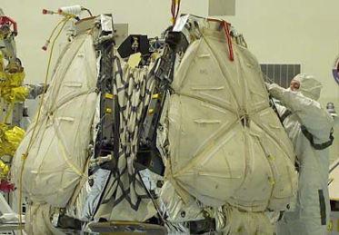

7 MER Spacecraft 7

8 MER Spacecraft Masses Rover kg Rover WEB kg Rover Mobility 34.5 kg Lander kg Lander Structure kg Bridle (on Lander) 10.6 kg Air Bags and Covers kg Landing kg Rockets Aeroshell Rover +Z Rover Suspension System Lander Aeroshell/BIP kg Heatshield 84.0 kg Backshell & Equipm t 81.3 kg RAD/TIRS & Mounting 68.5 kg BIP,SepNuts,Sirca, etc kg Parachute, canister, mortar 26.4 kg Entry kg 168 cm (66 ) Cruise Stage kg Cruise Stage kg LVA, SepNuts, etc kg Total kg Z cg = mm = Cruise Stage Parachute 265 cm (104.2 ) LVA 8
9 Launch Loads JPL in-house Modal MAC design loads for sizing (April 26, 2001) Model consistent with PDLC model Launch Vehicle Coupled Loads Analyses Three Spacecraft System Coupled Loads Analyses performed Preliminary Design Load Cycle (June 2001) Final Design Load Cycle (Jan 2002) Verification Load Cycle (Jan 2003) JPL adds mid-frequency loads to Boeing CLA to account for structureborne vibroacoustics Boeing CLA includes modes to 50 Hz JPL adds loads from 60 to 90 Hz for Liftoff and 50 to 90 Hz for Airload events MECO evaluation: add.5 g axial sinusoidal base-drive from 80 to 130 Hz, no results exceeded previous launch events Stage 3 Burn Performed at 6.5 g s static thrust with 75 RPM spin rate and 10 rad/sec 2 angular acceleration 9
10 Landing Loads Definition Objectives Empirically determine Landed Mass Center of Gravity acceleration and angular velocity and acceleration vectors Measure Lander tendon pin loads Data Reduction/Analyses (Total of 45 drop tests) Recorded Accelerometer data was processed using a least squares algorithm Statistical Analyses used to determined expected worst case acceleration environment General Test Configuration Impact Velocity (normal to surface) was 12 m/sec Ramp angle varied from 0, 45, 60 degrees (measured from horizontal) 60 degrees critical for primary impact 0 degrees used for second impact Airbag pressure varied from.85 to 1.25 psi 1 psi is the FLT airbag pressure 4 Airbags 6 Lobes per Airbag (diameter = 1.8 m) Ramp Upon release, gravity and a cluster of bungee cords accelerate the airbag/lander mass to the desired impact velocity. After impact with the rock-populated ramp, a large net catches the airbag. 10
11 Objectives Entry, Descent, & Landing Analyses Predict impact velocity to define landing loads drop test condition Verify Descent Rate Limiter (DRL) and Bridle loads Evaluate parachute cannister roller loads and clearance loss during lander separation Analyses ADAMS multi-body dynamic model Scope of Analysis: parachute deploy to ground impact Includes RAD/TIRS firing algorithm Conduct Monte Carlo dynamic simulations (500 each landing site) General Configuration RAD located inside of Aeroshell Backshell used for descent deceleration Three RAD s equally spaced around the Backshell Oriented degrees from vertical TIRS located outside of Aeroshell Backshell used to null out RADinduced horizontal velocity Three TIR s equally spaced around Backshell Oriented such that thrust vector coincides with Backshell center of gravity Triple Bridle attached to 3 places on backshell and on Lander side petal (FLL = 7900 lbs for Single Bridle) DRL attached to Backshell Interface Plate (BIP) and Lander side petal (DRL FLL = 603 lbs) ADD picture here DRL 11
12 Objectives Mobility Loads Definition Compute maximum wheel impact loads and suspension system station cut loads for design Compute loads at deployed appendages Analyses ADAMS transient analyses Scope of Analysis: includes all reasonable egress and surface mobility cases Assume maximum wheel drop of 25 cm in 3/8 Mars gravity field Assume µ s =.2, µ d =.4 between wheel and infinitely stiff ground Assume wheel stiffness is 2500 lbs/in General Configuration Deployed appendages and suspension system elements modeled to achieve frequency characteristics of detailed Finite Element Model PMA 4.5 Hz Lateral HGA 20 Hz Torsion,25 Hz Lat Suspension System 4 Hz Solar Arrays 8.3 Hz, 13 Hz, and 14 Hz bending IDD 11.6 Hz, 20.2 Hz Model Validation verified with drop testing and static testing of DTM unit: measured suspended mass CG accelerations to within 20% of model prediction Fundamental f = 4 Hz (lab linoleum surface conditions) 12
13 Mobility Loads Definition ADAMS model: Total Mass = 185 kg, 718 Degrees of Freedom Plots show transient simulation of Forward Wheel 25 cm Drop Case AB Y Fwd Rocker Wheel Impact Force (N) Time (sec) PMA Rover CG Z Acceleration SA SA HGA 10 SA Acceleration (m/sec2) Time (sec) 13
 Bogie Wheel Strut 1 2 9 Forward Bogie Aft Rocker 1 1 Rocker Deployment Actuator Forward Rocker 1")
14 Aft Bogie ADAMS Output Appendage Acceleration Loads Station Cut Forces CG acceleration and displacement Wheel Impact (600 lbs) Bogie Wheel Strut Forward Bogie Aft Rocker 1 1 Rocker Deployment Actuator Forward Rocker
15 Loads Environment Summary Launch: Minimum Design Load is Verification Load Cycle Results w/o midfrequency augmentation S/C acceleration: 2 g s lateral with 3.7 g s vertical.4 g s lateral with 6.6 g s vertical compression (Stage 3 Burn) Rover Acceleration: 4.9 g s lateral with 5.1 g s vertical.8 g s lateral with 6.7 g s vertical (Stage 3 Burn) Maximum component level acceleration: 17.6 g s for 17.8 kg IVSR on Cruise Stage Entry, Descent, Landing Aerobraking:.25 g s lateral with 8 g s vertical Parachute Inflation: 15.3 g s vertical (20,000 lbs cord load) RAD/TIRS Deceleration: 1950 lbs per RAD with 7900 lbs max single cord load (~6.5 g s) Landing Impact 1 st Bounce: a cg =21.2 g s, α=39.1 rad/sec 2, ω=13.8 rad/sec (or 31.2 g s at 50 cm) 2 nd Bounce: a cg =26.4 g s, α= 0.0 rad/sec 2, ω=13.0 rad/sec (or 35.0 g s at 50 cm) Mobility Loads 25 cm wheel drop cases: a (suspended mass)=3.4 g s with α = 82 rad/sec 2 15
16 Design Load Summary Launch Environment Critical Structure (2 g s lateral, 6.6 g s vertical) Cruise Stage/LVA, Backshell Interface Plate (BIP) Entry & Descent Critical Structure Aerobraking (.25 lateral, 8 g s vertical): Heatshield Parachute Inflation ( 15.3 g s vertical): Parachute Assembly, BIP beams Bridle End Snap (3 g s vertical): Descent Rate Limiter (Mar s gravity 3/8 g s) RAD firing: Backshell, Bridle Assembly Landing: 26.4 g s + ω of 13 rad/sec (30.7 g s when 25 cm from c.g.) Lander, Rover Assembly, Wheel Restraint System Surface Traverse: 1.9 g s drive,.19 g s lateral, 3.0 g s vertical at Rover CG (α = 76 rad/sec 2 ) Case AB w/1.25 loads uncertainty factor Mobility System, Wheels Deployed Solar Arrays & Deployed PMA Note: Mass of 10 kg corresponds to 30 g s by the MAC method 16
17 Definition of Flight Limit Load Critical Environment is Landing (Launch g s ~7.7 from Jan. 02 FDLC) March 01 Landing g s = 31.4 g s with rad/sec 2 Jan. 02 Landing g s = 21.2 g s with 207 rad/sec 2 Proper Design Load Methodology Must account for effect of distributed mass system on structural loading in angular acceleration field Must account for multi-directional nature of loading 2 m m m For each load component (tension,shear,etc) for each structural element, there will be a unique load vector to develop its maximum design load Developing Flight Limit Load - two options RSS of load components due to 3 orthogonal translational accelerations, RSS of load comp due to 3 ortho rotational accelerations about landed mass CG, then sum the two RSS values RSS of load components due to 3 orthogonal translational accelerations where g level represents extreme boundary of assembly Both methods will be conservative (probably not more than 10%) 17


18 Rover Loads Summary θ = 20.5 degrees Note: Output coordinate system is S/C Mass kg Design Load,g's VLC CLA Rover Component X Rover Web Y Rover Web Z Rover Web X Accel REM CG Y Accel REM CG Z Accel REM CG X Accel BATTERY CG Y Accel BATTERY CG Z Accel BATTERY CG X Accel MINI-TES CG Y Accel MINI-TES CG Z Accel MINI-TES CG X Accel PMA MDD Y Accel PMA MDD Z Accel PMA MDD X Accel HGA Dish Y Accel HGA Dish Z Accel HGA Dish X Accel HGA Gimble 6.35 total 43.1 Y Accel HGA Gimble 43.1 Z Accel HGA Gimble 43.1 X Accel IDD, note CLA is 30 degrees from s/c Y Accel IDD Z Accel IDD X Accel WEB/RED Aft-Top,MAC=20 g's rad/sec 2 Y Accel WEB/RED Aft-Top Z Accel WEB/RED Aft-Top Lift Mechanism Y Solar Array Right, Fwd wheel, vertical DOF
 with titanium rockers and bogies Wheel Restraint System: 4 radial restraints")
 in two places (3 DOF at motor, 2 DOF at hinge Three Primary to Primary 3 DOF Ball in Cup Joints (Cable")
19 Stowed and Deployed Rover Structural Concept (DTM tested to 33 g s in Centrifuge) Rover Warm Equipment Box (WEB) supported to Base Petal with 7 DOF constraint 3 Bipods and 1 Monopod Suspension System: 6 aluminum wheels, 6 drive actuators, 4 steering actuators (turn in place) with titanium rockers and bogies Wheel Restraint System: 4 radial restraints reacts 5 DOF with surface friction providing 6 th DOF rotational restraint (Cable Cutter Assbly) Solar Arrays: 3 Primary Arrays with 2 Secondary Arrays preloaded against +Y Primary Arrays Each Primary Array attached to Rover Equipment Deck (RED) in two places (3 DOF at motor, 2 DOF at hinge Three Primary to Primary 3 DOF Ball in Cup Joints (Cable Cutter Assbly) 19
 Temperature 55 C MAC Design Load = 10 g s (VLC = 9.1 g s) Panel Geometry M55J/BTCY: [45/0/-45/90]s layup, E = 14.")
20 Warm Electronics Box (WEB): Shear Panel construction with Rover Equipment Deck (RED) providing structural close-out Design Loads Mass = kg (Rover w/o Suspension System) Landing Design Load = 41.0 g s (Landing) Temperature 55 C MAC Design Load = 10 g s (VLC = 9.1 g s) Panel Geometry M55J/BTCY: [45/0/-45/90]s layup, E = 14.2 msi B-basis allowables: F tu = 79 ksi, F cu = 36 ksi Local Doublers and Core Fill used as required Astroquartz softening layer used at bonded titanium fittings to reduce bondline peaking stresses WEB ~38 ~34 ~21.6 ~14.4 RED Side walls (M55J/BTCY) Bottom Wall (M55J/BTCY) Honeycomb Construction Honeycomb Construction t t = 15 mm (.59") t t = 10 mm (.39") t f/s = 1 mm (.04"), 8 plies t f/s = 1 mm (.04"), 8 plies h c = 13 mm (.51") h c = 8 mm (.31") 5056 Al core (3.1 pcf) 5056 Al core (3.1 pcf) 1 mm doublers around -X sep. fitting 1 mm doublers in +X section 20
21 Warm Electronics Box (WEB) 90 Joint 60 Joint Joints Two Types 90 and 60 Joints Tested to demonstrate moment capability Bonded Joints HYSOL 9309 Adhesive E=3.0x10 5 psi; G=1.3x10 5 psi Nominal Bond Strength = 1143 psi at 60 C Equivalent Peak Stress Allowable = 4870 psi Peak Stress based on Volkerson Equations Interfaces Titanium Fittings Lander Interface (4 Sep-Nuts) Differential Interface (Housings) REM Struts (6 Struts) Lift Mechanism Interface (Fitting in WEB) Battery Interface (Fittings) RED Interface (Inserts) IDD Fitting IDD Fitting (Invar) Lift Mechanism Differential Rover I/F Points to Lander 21
 Lander bracket (dummy) Design Features: U joint - coplanar two axis pivot, designed as bipod or monopod Provides + 2 degrees of rotation")

22 WEB/ Lander Separation Joint Tie bar (2X) Axle pin (2x) Spider Rover yoke Flanged bushing (2x) Lander yoke (2x) Plain bushing (2x) Shim (opposite not shown) Lander bracket (dummy) Design Features: U joint - coplanar two axis pivot, designed as bipod or monopod Provides + 2 degrees of rotation and + 2 mm of translation Capable of transferring high loads in compact space (2 x3 by 1 depth) Interference fit between Axle pin and Rover Yoke Interference fit between Bushing & Spider and Bushing & Lander Yoke Interface to Rover Yoke is 45 degree cup/cone interface with 17,000 lbs preload 22
23 WEB/Lander Separation Joints Design Loads Mass = kg (Rover w/o Suspension System) Design Load = 41.0 g s (Landing) 1/2 in Bolt Forward Bipod Aft Bipod P = 6839 lbs P = 1170 lbs P = 6839 lbs V = 6055 lbs V = 7851 lbs V = 6055 lbs T = 1821 in-lbs Statically Tested to 17,000 lbs (12,000 Tension and 12,000 Shear) Materials Vascomax 300 Properties F y = 270 ksi F ult = 280 ksi F brg yd = 380 ksi F brg ult = 400 ksi ½ MP35N Bolt F y = 230 ksi F ult = 260 ksi Units are inches 23


24 RED/WEB Development Testing Achieved 16 g s lateral, 30 g s vertical Criteria: Mimic the critical landing environment Test in -35 C temperature environment (not achieved) Structural loads distribution is produced from a long duration impulse - static event Types of Tests Traditional Static Pull - difficult to load structure due to system mass distribution Sine or Random Vibe - risk of exciting modes of appendages w/o generating proper load distribution Centrifuge Test - cleanliness issues, cannot be done at cold temperature, off site logistics (schedule, handling fixtures, transportation,etc.) Sine Pulse - develops proper load distribution, dependent on shaker capability to achieve pseudo static testing 10 cycles to ramp up 2 cycles at peak shut down within 1 cycle 24

25 DTM Rover on Basepetal Centrifuge Tests Travel direction 30 degrees -Xsc +Y -Ysc Centrifuge arm -X 30 +X Centrifuge center +Ysc -Y +Xsc Load direction Objective: Test DTM Rover hardware to Landing loads: +33 g s X and +33 g s Y. Note Rover hardware oriented 30 degrees from S/C axes to generate maximum Rover/Lander I/F loads DTM Hardware: WEB, RED, REM struts, MiniTes Struts, Battery struts, Mobility System, Sep/Nut Assbly, Solar Array Substrates, Base Petal w/o LPA s Mass Mockups: PMA, HGA, IDD, REM, MiniTes, Battery Note DTM RED/WEB tested to 30 g s Vertical Z-axis during Sine Pulse Test 25
 FLT Mobility Sys, FLT Lift Assy MM Battery FLT Basepetal w/ FLT LPA s Input ASD.")
 Random: 3.")
26 Flight Rover 1 & 2 on Basepetal Random & Sine Pulse Tests (3 Axes) Rover 1 & 2 FLT WEB/RED, FLT PMA, FLT HGA FLT IDD, FLT REM, FLT MiniTes Substrate Solar Arrays (FLT on Rover 1) FLT Mobility Sys, FLT Lift Assy MM Battery FLT Basepetal w/ FLT LPA s Input ASD.02 g 2 /Hz from 80 to 450 Hz Sine Pulse Input: 11 g s lat, 15 g s vert Objective: Perform Protoflight Landing Level Workmanship Random and Sine Burst Tests (25 msec or 20 Hz) Random: 3.9 g rms, from 20 to 2000 Hz Sine Pulse: +14 g s lateral, +22 g s vertical (based on measured Interface force) 26
27 Mobility Loads and Dynamic Testing ADAMS model: Total Mass = 180 kg 718 Degrees of Freedom Simulation of Forward Wheel 25 cm Drop Flight Mass Testing on Earth w/1.2 Test Factor Mass of Test Rover = kg Drop Height = 14.2 cm (31.6 cm on Mars) * Drop height adjusted for reduced mass and Earth gravity affects Forward Rocker Two Wheel Drop Test Results Web Center of Mass Acceleration X Dir. max (g) Y Dir. max (g) Z Dir. max (g) Primary S/A Normal Accel (g) Secondary S/A Normal Accel (g) Aft (-X) S/A Normal Accel (g) Test Predicted
28 Completed Structural Verification Tests DTM, FLT Aeroshell Static & Stiffness Test FLT Cruise Stage/LVA/Clamp/PAF - Static & Modal Test DTM Rover (w/o suspension) Pulse - 16g Lateral & 30g Vertical Input DTM Rover/Basepetal Fixed Base Modal; Random; Basedrive Modal; Pulse ~ 14g Lateral* & 22g Vertical* DTM Rover/Basepetal Centrifuge ~ 33g ±X & ±Y Axes Rover Suspension (Mars Landing Configuration) DTM Wheel Restraint Static DTM Rover Suspension (Mars Traverse Configuration) Rocker/Bogey Static & Stiffness End to End Suspension Stiffness Wheels Static Strength & Stiffness DTM, FLT Lander Petals Basepetal Static & Stiffness Flt. Base & Side Petals (Each) Static & Stiffness FLT S/C 1 Random; Fixed Base Modal; Acoustic 1/'02 3/'02 5/'02 8/'02 8/'02 8/'02 7/'02 8/'02 5/'02 5/'02 7/'02 8/'02 10/'02,1/'03 FLT Rover 2 on FLT Basepetal Random; Pulse (14 g s lat, 19.3 g s vert)* 12/'02 FLT Rover 1 on FLT Basepetal Random; Pulse (13.7 g s lat, 21 g s vert)* 2/'03 Sufficient Static and Dynamic Testing has been completed to verify design and workmanship of the MER primary payload * Based on measured interface load 28
DYNAMIC SIMULATION OF MARS-03 ENTRY, DESCENT AND LANDING SYSTEM
 DYNAMIC SIMULATION OF MARS-03 ENTRY, DESCENT AND LANDING SYSTEM Chia-Yen Peng and Walter Tsuha Jet Propulsion Laboratory California Institute of Technology 4800 Oak Grove Drive Pasadena, CA 91109 ABSTRACT.
Eliminating the Need for Payload-specific Coupled Loads Analysis
 Eliminating the Need for Payload-specific Coupled Loads Analysis Tom Sarafin and Seth Kovnat Instar Engineering and Consulting, Inc. 6901 S. Pierce St., Suite 200, Littleton, CO 80128; 303-973-2316 tom.sarafin@instarengineering.com
CHAPTER 6 ENVIRONMENTAL CONDITIONS
 ENVIRONMENTAL CONDITIONS 6.1 Summary This chapter introduces the natural environment of launch site, thermal environment during SC operation, thermal and mechanical environments (vibration, shock & noise)
of the attachment to the telescope in order to provide stability at touch down in soft terrains. ABSTRACT
 X-38 LANDING GEAR QUALIFICATION TESTING Eduardo Urgoiti SENER AV. Zugazarte 56 Las Arenas 4893 Bizkaia SPAIN Tel 34 94 481764, Fax 34 94 481763 e-mail: eduardo.urgoiti@sener.es ABSTRACT The Landing Gear
Loads, Structures, and Mechanisms Design Project ENAE 483 Fall 2012
 Loads, Structures, and Mechanisms Design Project Fall 2012 Stephanie Bilyk Leah Krombach Josh Sloane Michelle Sultzman Mission Specifications Design vehicle for lunar exploration mission 10 day mission
EFFECTIVE SOLUTIONS FOR SHOCK AND VIBRATION CONTROL
 EFFECTIVE SOLUTIONS FOR SHOCK AND VIBRATION CONTROL Part 1 Alan Klembczyk TAYLOR DEVICES, INC. North Tonawanda, NY Part 2 Herb LeKuch Shocktech / 901D Monsey, NY SAVIAC Tutorial 2009 Part 1 OUTLINE Introduction
USA FALCON 1. Fax: (310) Telephone: (310) Fax: (310) Telephone: (310) Fax: (310)
 Telephone: (310) Fax: (310) Telephone: (310) Fax: (310)") 1. IDENTIFICATION 1.1 Name FALCON 1 1.2 Classification Family : FALCON Series : FALCON 1 Version : FALCON 1 Category : SPACE LAUNCH VEHICLE Class : Small Launch Vehicle (SLV) Type : Expendable Launch Vehicle
1. IDENTIFICATION 1.1 Name FALCON 1 1.2 Classification Family : FALCON Series : FALCON 1 Version : FALCON 1 Category : SPACE LAUNCH VEHICLE Class : Small Launch Vehicle (SLV) Type : Expendable Launch Vehicle
INTERMEDIATE EXPERIMENTAL VEHICLE. JETTISON MECHANISM ENGINEERING AND TEST
 INTERMEDIATE EXPERIMENTAL VEHICLE. JETTISON MECHANISM ENGINEERING AND TEST L. Caldirola (1), B. Schmid (1) (1) RUAG Schweiz AG, RUAG Space, Schaffhauserstrasse 580, 8052 Zürich Email: luca.caldirola@ruag.com
Development of a Dual Mode Vibration Isolator for a Laser Communication Terminal
 Development of a Dual Mode D-Strut@ Vibration Isolator for a Laser Communication Terminal Dale T. Ruebsamen, James Boyd*, Joe Vecera. and Roger Nagel Abstract This paper provides a review of the development
Coupled Aero-Structural Modelling and Optimisation of Deployable Mars Aero-Decelerators
 Coupled Aero-Structural Modelling and Optimisation of Deployable Mars Aero-Decelerators Lisa Peacocke, Paul Bruce and Matthew Santer International Planetary Probe Workshop 11-15 June 2018 Boulder, CO,
Alan R. Klembczyk, Chief Engineer Taylor Devices, Inc. North Tonawanda, NY
 SIMULATION, DEVELOPMENT, AND FIELD MEASUREMENT VALIDATION OF AN ISOLATION SYSTEM FOR A NEW ELECTRONICS CABINET IN THE SPACE SHUTTLE LAUNCH ENVIRONMENT WITHIN THE MOBILE LAUNCH PLATFORM Alan R. Klembczyk,
CRITICAL DESIGN PRESENTATION
 CRITICAL DESIGN PRESENTATION UNIVERSITY OF SOUTH ALABAMA LAUNCH SOCIETY BILL BROWN, BEECHER FAUST, ROCKWELL GARRIDO, CARSON SCHAFF, MICHAEL WIESNETH, MATTHEW WOJCIECHOWSKI ADVISOR: CARLOS MONTALVO MENTOR:
APS 113 ELECTRO-SEIS Long Stroke Shaker with Linear Ball Bearings Page 1 of 5
 Long Stroke Shaker with Linear Ball Bearings Page 1 of 5 The ELECTRO-SEIS shaker is a long stroke, electrodynamic force generator specifically designed to be used alone or in arrays for studying dynamic
APS 420 ELECTRO-SEIS Long Stroke Shaker with Linear Ball Bearings Page 1 of 5
 Long Stroke Shaker with Linear Ball Bearings Page 1 of 5 The APS 420 ELECTRO-SEIS shaker is a long stroke, electrodynamic force generator specifically designed to be used alone or in arrays for studying
Lunette: A Global Network of Small Lunar Landers
 Lunette: A Global Network of Small Lunar Landers Leon Alkalai and John O. Elliott Jet Propulsion Laboratory California Institute of Technology LEAG/ILEWG 2008 October 30, 2008 Baseline Mission Initial
Rapid Coupled Loads Analysis and Spacecraft Load Reduction using SoftRide
 Rapid Coupled Loads Analysis and Spacecraft Load Reduction using SoftRide SSC09-IX-2 Raman S. Johal Paul S. Wilke Conor D. Johnson CSA Engineering, Inc. 2565 Leghorn Street Mountain View, CA 94043 (650)
Development and Testing of a High Compact Stepper Motor Mechanism
 Development and Testing of a High Compact Stepper Motor Mechanism Jörg Schmidt * and Greg Wright ** Abstract The Laboratory for Atmospheric and Space Physics (LASP) has developed for the Mars Atmosphere
NASA USLI PRELIMINARY DESIGN REVIEW. University of California, Davis SpaceED Rockets Team
 NASA USLI 2012-13 PRELIMINARY DESIGN REVIEW University of California, Davis SpaceED Rockets Team OUTLINE School Information Launch Vehicle Summary Motor Selection Mission Performance and Predictions Structures
LOW SHOCK RELEASE UNIT EASY RESETTABLE AND 100 % REUSABLE. Jens Müller 1, Christoph Zauner 2
 LOW SHOCK RELEASE UNIT EAS RESETTABLE AND 100 % REUSABLE Jens Müller 1, Christoph Zauner 2 1 Astrium GmbH, 2 Chair of Lightweight Structures - Technical University of Munich Astrium GmbH, 81663 München
APS 400 ELECTRO-SEIS. Long Stroke Shaker Page 1 of 5. Applications. Features
 Long Stroke Shaker Page 1 of 5 The APS 400 ELECTRO-SEIS is a force generator specifically designed to be used alone or in arrays for studying dynamic response characteristics of various structures. It
Flight Readiness Review Addendum: Full-Scale Re-Flight. Roll Induction and Counter Roll NASA University Student Launch.
 Flight Readiness Review Addendum: Full-Scale Re-Flight Roll Induction and Counter Roll 2016-2017 NASA University Student Launch 27 March 2017 Propulsion Research Center, 301 Sparkman Dr. NW, Huntsville
Riverhawk Company 215 Clinton Road New Hartford NY (315) Free-Flex Flexural Pivot Engineering Data
 Free-Flex Flexural Pivot Engineering Data") Riverhawk Company 215 Clinton Road New Hartford NY (315)768-4937 Free-Flex Flexural Pivot Engineering Data PREFACE Patented Flexural Pivot A unique bearing concept for applications with limited angular
Riverhawk Company 215 Clinton Road New Hartford NY (315)768-4937 Free-Flex Flexural Pivot Engineering Data PREFACE Patented Flexural Pivot A unique bearing concept for applications with limited angular
HIGH LOAD LOW SHOCK RELEASE UNIT (30 kn)
") HIGH LOAD LOW SHOCK RELEASE UNIT (30 kn) Jens Müller (1), Christian Anderau (2) (1) Astrium GmbH, 81663 München (Germany), Email: Jens.mueller@astrium.eads.net (2) RUAG Aerospace AG, Widenholzstr. 1, 8304
HIGH LOAD LOW SHOCK RELEASE UNIT (30 kn) Jens Müller (1), Christian Anderau (2) (1) Astrium GmbH, 81663 München (Germany), Email: Jens.mueller@astrium.eads.net (2) RUAG Aerospace AG, Widenholzstr. 1, 8304
SPMM OUTLINE SPECIFICATION - SP20016 issue 2 WHAT IS THE SPMM 5000?
 SPMM 5000 OUTLINE SPECIFICATION - SP20016 issue 2 WHAT IS THE SPMM 5000? The Suspension Parameter Measuring Machine (SPMM) is designed to measure the quasi-static suspension characteristics that are important
Development of Shape Memory Alloy (SMA) Actuated Mechanisms for Spacecraft Release Applications
 Actuated Mechanisms for Spacecraft Release Applications") Development of Shape Memory Alloy (SMA) Actuated Mechanisms for Spacecraft Release Applications Shawn H. Smith Starsys Research Corporation, 4909 Nautilus Ct. N.,Boulder, CO 80301, 303-530-1925 smith@starsys.com
Development of Shape Memory Alloy (SMA) Actuated Mechanisms for Spacecraft Release Applications Shawn H. Smith Starsys Research Corporation, 4909 Nautilus Ct. N.,Boulder, CO 80301, 303-530-1925 smith@starsys.com
FLIGHT READINESS REVIEW TEAM OPTICS
 FLIGHT READINESS REVIEW TEAM OPTICS LAUNCH VEHICLE AND PAYLOAD DESIGN AND DIMENSIONS Vehicle Diameter 4 Upper Airframe Length 40 Lower Airframe Length 46 Coupler Band Length 1.5 Coupler Length 12 Nose
Ares V: Supporting Space Exploration from LEO to Beyond
 Ares V: Supporting Space Exploration from LEO to Beyond American Astronautical Society Wernher von Braun Memorial Symposium October 21, 2008 Phil Sumrall Advanced Planning Manager Ares Projects Office
STICTION/FRICTION IV STICTION/FRICTION TEST 1.1 SCOPE
 Page 1 of 6 STICTION/FRICTION TEST 1.0 STICTION/FRICTION TEST 1.1 SCOPE Static friction (stiction) and dynamic (running) friction between the air bearing surface of sliders in a drive and the corresponding
GLAST LAT Project 3-4 May MGSE Design. LAT Environmental Test PDR 1
 LAT LAT Environmental Environmental Test Test Planning Planning and and Design Design Review Review 3-4 3-4 4 May May 2005 2005 MGSE Design Martin Martin Nordby Nordby Mike Mike Foss Foss Marc Marc Campell
Welcome to Vibrationdata
 Welcome to Vibrationdata Acoustics Shock Vibration Signal Processing September 2010 Newsletter Cue the Sun Feature Articles This month s newsletter continues with the space exploration theme. The Orion
Jordan High School Rocketry Team. A Roll Stabilized Video Platform and Inflatable Location Device
 Jordan High School Rocketry Team A Roll Stabilized Video Platform and Inflatable Location Device Mission Success Criteria No damage done to any person or property. The recovery system deploys as expected.
CRITICAL DESIGN REVIEW. University of South Florida Society of Aeronautics and Rocketry
 CRITICAL DESIGN REVIEW University of South Florida Society of Aeronautics and Rocketry 2017-2018 AGENDA 1. Launch Vehicle 2. Recovery 3. Testing 4. Subscale Vehicle 5. Payload 6. Educational Outreach 7.
Rotational Kinematics and Dynamics Review
 Rotational Kinematics and Dynamics Review 1. The Earth takes slightly less than one day to complete one rotation about the axis passing through its poles. The actual time is 8.616 10 4 s. Given this information,
Development and validation of a vibration model for a complete vehicle
 Development and validation of a vibration for a complete vehicle J.W.L.H. Maas DCT 27.131 External Traineeship (MW Group) Supervisors: M.Sc. O. Handrick (MW Group) Dipl.-Ing. H. Schneeweiss (MW Group)
Critical Design Review
 Critical Design Review University of Illinois at Urbana-Champaign NASA Student Launch 2017-2018 Illinois Space Society 1 Overview Illinois Space Society 2 Launch Vehicle Summary Javier Brown Illinois Space
CALL FOR IDEAS FOR THE RE-USE OF THE MARS EXPRESS PLATFORM PLATFORM CAPABILITIES. D. McCoy
 Mars Express Reuse: Call for Ideas CALL FOR IDEAS FOR THE RE-USE OF THE MARS EXPRESS PLATFORM PLATFORM CAPABILITIES D. McCoy PARIS 23 MARCH 2001 page 1 Mars Express Reuse: Call for Ideas PRESENTATION CONTENTS
Mars Exploration Rover Entry, Descent, & Landing: A Thermal Perspective
 Mars Exploration Rover Entry, Descent, & Landing: A Thermal Perspective Glenn T. Tsuyuki, Eric T. Sunada, Keith S. Novak, Gary M. Kinsella, and Charles J. Phillips Jet Propulsion Laboratory California
Mars 2018 Mission Status and Sample Acquisition Issues
 Mars 2018 Mission Status and Sample Acquisition Issues Presentation to the Planetary Protection Subcommittee Charles Whetsel Manager, Advanced Studies and Program Architecture Office Christopher G. Salvo
LOW SHOCK NON-EXPLOSIVE ACTUATOR
 LOW SHOCK NON-EXPLOSIVE ACTUATOR Bob Chang (1), Patrick Laughlin (2), Terry Sasaki (3) (1) Eaton, 750 W. Ventura Blvd., Camarillo CA, 93010, USA; e-mail: bobchang@eaton.com (2) Eaton, 750 W. Ventura Blvd.,
Chapter 7. Shafts and Shaft Components
 Chapter 7 Shafts and Shaft Components 2 Chapter Outline Introduction Shaft Materials Shaft Layout Shaft Design for Stress Deflection Considerations Critical Speeds for Shafts Miscellaneous Shaft Components
From MARS To MOON. V. Giorgio Director of Italian Programs. Sorrento, October, All rights reserved, 2007, Thales Alenia Space
 From MARS To MOON Sorrento, October, 2007 V. Giorgio Director of Italian Programs Page 2 Objectives of this presentation is to provide the Lunar Exploration Community with some information and status of
Development of a Self-latching Hold-down RElease Kinematic (SHREK)
") Development of a Self-latching Hold-down RElease Kinematic (SHREK) Ruggero Cassanelli * Abstract SHREK (Self-latching Hold-down Release Kinematic), is an innovative shape memory actuated hold down and
Development of a Self-latching Hold-down RElease Kinematic (SHREK) Ruggero Cassanelli * Abstract SHREK (Self-latching Hold-down Release Kinematic), is an innovative shape memory actuated hold down and
DEVELOPMENT OF AN EUROPEAN EDDY CURRENT DAMPER (ECD-100)
") DEVELOPMENT OF AN EUROPEAN EDDY CURRENT DAMPER (ECD-100) 1 ABSTRACT Authors M. Hofer & M. Humphries Oerlikon Space AG, Schaffhauserstr. 580 CH-8052 Zürich-Seebach Switzerland Oerlikon Space have been designing
DEVELOPMENT OF AN EUROPEAN EDDY CURRENT DAMPER (ECD-100) 1 ABSTRACT Authors M. Hofer & M. Humphries Oerlikon Space AG, Schaffhauserstr. 580 CH-8052 Zürich-Seebach Switzerland Oerlikon Space have been designing
DemoSat-B User s Guide
 January 5, 2013 Authors: Chris Koehler & Shawn Carroll Revisions Revision Description Date Approval DRAFT Initial release 7/31/2009 1 Updated for 2011 2012 program dates, added revision page 9/27/11 LEM
Challenges of Designing the MarsNEXT Network
 Challenges of Designing the MarsNEXT Network IPPW-6, Atlanta, June 26 th, 2008 Kelly Geelen kelly.geelen@astrium.eads.net Outline Background Mission Synopsis Science Objectives and Payload Suite Entry,
Brüel & Kjær and LDS The Perfect Match SHORT FORM CATALOGUE
 Brüel & Kjær and LDS The Perfect Match SHORT FORM CATALOGUE 4 Aerospace For any aircraft, helicopter, space vehicle or ballistic device, reliability is the number one priority. By using our vibration test
Design and development of the Nozzle Deployment Mechanism for the Vinci Cryogenic Engine
 Design and development of the Nozzle Deployment Mechanism for the Vinci Cryogenic Engine Sigmunn Strøm (1), Johan Krabberød (1), Olivier Condaminet (2) (1) Kongsberg Defence and Aerospace, Kirkegårdsveien
Testing Orion s Fairing Separation System
 Testing Orion s Fairing Separation System Henry Martinez*, Chris Cloutier*, Heber Lemmon*, Daniel Rakes*, Joe Oldham* and Keith Schlagel* Abstract Traditional fairing systems are designed to fully encapsulate
AXLE HOUSING AND UNITIZE BEARING PACK SET MODAL CHARACTERISATION
 F2004F461 AXLE HOUSING AND UNITIZE BEARING PACK SET MODAL CHARACTERISATION 1 Badiola, Virginia*, 2 Pintor, Jesús María, 3 Gainza, Gorka 1 Dana Equipamientos S.A., España, 2 Universidad Pública de Navarra,
Mathematical Modelling and Simulation Of Semi- Active Suspension System For An 8 8 Armoured Wheeled Vehicle With 11 DOF
 Mathematical Modelling and Simulation Of Semi- Active Suspension System For An 8 8 Armoured Wheeled Vehicle With 11 DOF Sujithkumar M Sc C, V V Jagirdar Sc D and MW Trikande Sc G VRDE, Ahmednagar Maharashtra-414006,
Modeling of 17-DOF Tractor Semi- Trailer Vehicle
 ISSN 2395-1621 Modeling of 17-DOF Tractor Semi- Trailer Vehicle # S. B. Walhekar, #2 D. H. Burande 1 sumitwalhekar@gmail.com 2 dhburande.scoe@sinhgad.edu #12 Mechanical Engineering Department, S.P. Pune
GLAST Large Area Telescope:
 GLAST Large Area Telescope: Gamma-ray Large Area Space Telescope MGSE Integration Readiness Status Two Tower Operations Eric Gawehn SU-SLAC LAT I&T MGSE Dept. Manager egawehn@slac.stanford.edu 650 926
Full Vehicle Durability Prediction Using Co-simulation Between Implicit & Explicit Finite Element Solvers
 Full Vehicle Durability Prediction Using Co-simulation Between Implicit & Explicit Finite Element Solvers SIMULIA Great Lakes Regional User Meeting Oct 12, 2011 Victor Oancea Member of SIMULIA CTO Office
Precision Modules PSK
 Precision Modules PSK The Drive & Control Company Rexroth Linear Motion Technology Ball Rail Systems Roller Rail Systems Standard Ball Rail Systems Super Ball Rail Systems Ball Rail Systems with Aluminum
Assemblies for Parallel Kinematics. Frank Dürschmied. INA reprint from Werkstatt und Betrieb Vol. No. 5, May 1999 Carl Hanser Verlag, München
 Assemblies for Parallel Kinematics Frank Dürschmied INA reprint from Werkstatt und Betrieb Vol. No. 5, May 1999 Carl Hanser Verlag, München Assemblies for Parallel Kinematics Frank Dürschmied Joints and
The University of Melbourne Engineering Mechanics
 The University of Melbourne 436-291 Engineering Mechanics Tutorial Twelve General Plane Motion, Work and Energy Part A (Introductory) 1. (Problem 6/78 from Meriam and Kraige - Dynamics) Above the earth
Procedia Engineering 00 (2009) Mountain bike wheel endurance testing and modeling. Robin C. Redfield a,*, Cory Sutela b
 Mountain bike wheel endurance testing and modeling. Robin C. Redfield a,*, Cory Sutela b") Procedia Engineering (29) Procedia Engineering www.elsevier.com/locate/procedia 9 th Conference of the International Sports Engineering Association (ISEA) Mountain bike wheel endurance testing and modeling
Procedia Engineering (29) Procedia Engineering www.elsevier.com/locate/procedia 9 th Conference of the International Sports Engineering Association (ISEA) Mountain bike wheel endurance testing and modeling
Grand Challenge VHG Test Article 2 Test 4
 Grand Challenge Prediction Article #: TA2 Test 4 Test Apparatus: VHG Organization: ARDEC Grand Challenge VHG Test Article 2 Test 4 Miroslav Tesla, Jennifer A. Cordes, Janet Wolfson RDAR-MEF-E, Building
Dual Spacecraft System
 Dual Spacecraft System Brent Viar 1, Benjamin Colvin 2 and Catherine Andrulis 3 United Launch Alliance, Littleton, CO 80127 At the AIAA Space 2008 Conference & Exposition, we presented a paper on the development
CONCURRENT ACTUATOR DEVELOPMENT FOR THE MARS EXPLORATION ROVER INSTRUMENT DEPLOYMENT DEVICE
 CONCURRENT ACTUATOR DEVELOPMENT FOR THE MARS EXPLORATION ROVER INSTRUMENT DEPLOYMENT DEVICE Richard Fleischner Alliance Spacesystems, Inc. 1250 Lincoln Avenue, Suite 100 Pasadena, California 91103, USA
Ares I-X Launch Vehicle Modal Test Overview
 Ares I-X Launch Vehicle Modal Test Overview Proceedings of the IMAC-XXVIII February 1 4, 2010, Jacksonville, Florida USA 2010 Society for Experimental Mechanics Inc. Ralph D. Buehrle NASA Langley Research
Aircraft Level Dynamic Model Validation for the STOVL F-35 Lightning II
 Non-Export Controlled Information Releasable to Foreign Persons Aircraft Level Dynamic Model Validation for the STOVL F-35 Lightning II David A. Boyce Flutter Technical Lead F-35 Structures Technologies
New Reliability Assessment Methods for MEMS. Prof. Mervi Paulasto-Kröckel Electronics Integration and Reliability
 New Reliability Assessment Methods for MEMS Prof. Mervi Paulasto-Kröckel Electronics Integration and Reliability Aalto University A merger of leading Finnish universities in 2010: Helsinki School of Economics
NASA Glenn Research Center Intelligent Power System Control Development for Deep Space Exploration
 National Aeronautics and Space Administration NASA Glenn Research Center Intelligent Power System Control Development for Deep Space Exploration Anne M. McNelis NASA Glenn Research Center Presentation
Rocketry Projects Conducted at the University of Cincinnati
 Rocketry Projects Conducted at the University of Cincinnati 2009-2010 Grant Schaffner, Ph.D. (Advisor) Rob Charvat (Student) 17 September 2010 1 Spacecraft Design Course Objectives Students gain experience
10 Thrust ball bearings
 10 Thrust ball bearings Designs and variants.............. 1010 Single direction thrust ball bearings... 1010 Double direction thrust ball bearings.. 1010 Cages............................ 1010 Bearings
Vibration Fundamentals Training System Hands-On Turnkey System for Teaching Vibration Fundamentals
 Vibration Fundamentals Training System Hands-On Turnkey System for Teaching Vibration Fundamentals www.haopute.com email:info@haopute.com phone:02884625157 mobile:18982185717 An Ideal Tool for Optimizing
WhirliGig Transfer Vehicle for motor-driven, restartable A.G. Tom Sullivan June, 2002
 WhirliGig Transfer Vehicle for motor-driven, restartable A.G. Tom Sullivan June, 2002 Thrusters (notional) Prop tanks, Ar Rankine Engines (3) Rxtr Radiator, both sides ~25 m Side view 4-5 m Flow of potassium
TEST METHODS CONCERNING TRANSPORT EQUIPMENT
 PART IV TEST METHODS CONCERNING TRANSPORT EQUIPMENT - 403 - CONTENTS OF PART IV Section Page 40. INTRODUCTION TO PART IV... 407 40.1 PURPOSE... 407 40.2 SCOPE... 407 41. DYNAMIC LONGITUDINAL IMPACT TEST
On the feasibility of a fast track return to Mars
 On the feasibility of a fast track return to Mars Mars Lander(s) 2011 Mars Demonstration Landers (MDL) Page 1 Technology Demonstrators SMART 1 SMART 2 LISA PF Solar Electric Propulsion Drag Free Control
Mars Science Laboratory Differential Restraint: The Devil is in the Details
 Mars Science Laboratory Differential Restraint: The Devil is in the Details Elizabeth Jordan * Abstract The Differential Restraint, a mechanism used on the Mars Science Laboratory (MSL) rover to maintain
COMMITMENT. &SOLUTIONS Act like someone s life depends on what we do.
 DISTRIBUTION DISTRIBUTION STATEMENT STATEMENT D. Distribution A. Approved authorized for public to the release Department of Defense and U.S. DoD contractors only; Critical Technology; May-17 Other requests
Analysis and control of vehicle steering wheel angular vibrations
 Analysis and control of vehicle steering wheel angular vibrations T. LANDREAU - V. GILLET Auto Chassis International Chassis Engineering Department Summary : The steering wheel vibration is analyzed through
Studying the Positioning Accuracy
 Ball Screw Studying the Positioning Accuracy Causes of Error in the Positioning Accuracy Point of Selection Studying the Positioning Accuracy The causes of error in the positioning accuracy include the
Quantum Series Size 17, 23, 34 and 56 Brushless Servo Motors Frameless and Housed Engineering Guide
 MACCON GmbH Kübachstr.9 D-81543 München Tel +49-89-65122()-21 Fax +49-89-655217 Quantum Series Size 17, 23, 34 and 56 Brushless Servo Motors Frameless and Housed Engineering Guide Selection Guide Quantum
Use of Simpack at the DaimlerChrysler Commercial Vehicles Division
 Use of Simpack at the DaimlerChrysler Commercial Vehicles Division Dr. Darko Meljnikov 22.03.2006 Truck Product Creation (4P) Content Introduction Driving dynamics and handling Braking systems Vehicle
Skid against Curb simulation using Abaqus/Explicit
 Visit the SIMULIA Resource Center for more customer examples. Skid against Curb simulation using Abaqus/Explicit Dipl.-Ing. A. Lepold (FORD), Dipl.-Ing. T. Kroschwald (TECOSIM) Abstract: Skid a full vehicle
Reentry Demonstration Plan of Flare-type Membrane Aeroshell for Atmospheric Entry Vehicle using a Sounding Rocket
 AIAA ADS Conference 2011 in Dublin 1 Reentry Demonstration Plan of Flare-type Membrane Aeroshell for Atmospheric Entry Vehicle using a Sounding Rocket Kazuhiko Yamada, Takashi Abe (JAXA/ISAS) Kojiro Suzuki
VACCO ChEMS. Micro Propulsion Systems
 VACCO ChEMS Micro Propulsion Systems 14 Flight Systems and Counting 1 Heritage MEPSI Micro Propulsion System Micro Propulsion System 1U CubeSat Provided to AFRL for the Aerospace Corporation MEMS Pico-Satellite
HPR Staging & Air Starting By Gary Stroick
 Complex Rocket Design Considerations HPR Staging & Air Starting By Gary Stroick 1. Tripoli Safety Code 2. Technical Considerations 3. Clusters/Air Starts 4. Staging 5. Summary 2 1. Complex High Power Rocket.
Entry, Descent, and Landing Technology Concept Trade Study for Increasing Payload Mass to the Surface of Mars
 Entry, Descent, and Landing Technology Concept Trade Study for Increasing Payload Mass to the Surface of Mars Juan R. Cruz, Alicia D. Cianciolo, Richard W. Powell, Lisa C. Simonsen NASA Langley Research
Vehicle Dynamic Simulation Using A Non-Linear Finite Element Simulation Program (LS-DYNA)
") Vehicle Dynamic Simulation Using A Non-Linear Finite Element Simulation Program (LS-DYNA) G. S. Choi and H. K. Min Kia Motors Technical Center 3-61 INTRODUCTION The reason manufacturers invest their time
Vehicle Dynamic Simulation Using A Non-Linear Finite Element Simulation Program (LS-DYNA) G. S. Choi and H. K. Min Kia Motors Technical Center 3-61 INTRODUCTION The reason manufacturers invest their time
Courtesy of Steven Engineering, Inc - (800) PATENTED
 PATENTED") PRECISION RING DRIVE SYSTEMS Based on Nexen s innovative Roller Pinion technology, Nexen Ring Drive Systems come complete with a precision grade, high capacity bearing and drive mechanism in a rigid housing.
PRECISION RING DRIVE SYSTEMS Based on Nexen s innovative Roller Pinion technology, Nexen Ring Drive Systems come complete with a precision grade, high capacity bearing and drive mechanism in a rigid housing.
III B.Tech I Semester Supplementary Examinations, May/June
 Set No. 1 III B.Tech I Semester Supplementary Examinations, May/June - 2015 1 a) Derive the expression for Gyroscopic Couple? b) A disc with radius of gyration of 60mm and a mass of 4kg is mounted centrally
SPMM OUTLINE SPECIFICATION - SP20016 issue 2 WHAT IS THE SPMM 5000?
 SPMM 5000 OUTLINE SPECIFICATION - SP20016 issue 2 WHAT IS THE SPMM 5000? The Suspension Parameter Measuring Machine (SPMM) is designed to measure the quasi-static suspension characteristics that are important
Linear Actuator with Ball Screw Series OSP-E..S. Contents Description Overview Technical Data Dimensions 89
 Linear Actuator with Ball Screw Series OSP-E..S Contents Description Page Overview 79-82 Technical Data 83-88 Dimensions 89 79 The System Concept ELECTRIC LINEAR ACTUATOR FOR HIGH ACCURACY APPLICATIONS
Reduction of Self Induced Vibration in Rotary Stirling Cycle Coolers
 Reduction of Self Induced Vibration in Rotary Stirling Cycle Coolers U. Bin-Nun FLIR Systems Inc. Boston, MA 01862 ABSTRACT Cryocooler self induced vibration is a major consideration in the design of IR
Axial piston variable pump A10V(S)O Series 31
O Series 31") Axial piston variable pump A10V()O eries 31 RE 92701 Edition: 06.2016 Replaces: 01.2012 ize 18 (A10VO) izes 28 to 1 (A10VO) Nominal pressure 280 bar Maximum pressure 350 bar Open circuit Features Variable
Axial piston variable pump A10V()O eries 31 RE 92701 Edition: 06.2016 Replaces: 01.2012 ize 18 (A10VO) izes 28 to 1 (A10VO) Nominal pressure 280 bar Maximum pressure 350 bar Open circuit Features Variable
ISO 8855 INTERNATIONAL STANDARD. Road vehicles Vehicle dynamics and road-holding ability Vocabulary
 INTERNATIONAL STANDARD ISO 8855 Second edition 2011-12-15 Road vehicles Vehicle dynamics and road-holding ability Vocabulary Véhicules routiers Dynamique des véhicules et tenue de route Vocabulaire Reference
Influence of Kink Protection Systems on a Tram Passing Through Curve
 Influence of Kink Protection Systems on a Tram Passing Through Curve Grzegorz Fira, Tomas Załuski, Albert Szałajko,, Augsburg, 8-9 October www.ec-e.pl Content Existing system of kink protection for a tram
Experimental Verification of the Implementation of Bend-Twist Coupling in a Wind Turbine Blade
 Experimental Verification of the Implementation of Bend-Twist Coupling in a Wind Turbine Blade Authors: Marcin Luczak (LMS), Kim Branner (Risø DTU), Simone Manzato (LMS), Philipp Haselbach (Risø DTU),
Auburn University Student Launch. PDR Presentation November 16, 2015
 Auburn University Student Launch PDR Presentation November 16, 2015 Project Aquila Vehicle Dimensions Total Length of 69.125 inches Inner Diameter of 5 inches Outer Diameter of 5.25 inches Estimated mass
Georgia Tech NASA Critical Design Review Teleconference Presented By: Georgia Tech Team ARES
 Georgia Tech NASA Critical Design Review Teleconference Presented By: Georgia Tech Team ARES 1 Agenda 1. Team Overview (1 Min) 2. 3. 4. 5. 6. 7. Changes Since Proposal (1 Min) Educational Outreach (1 Min)
Motor Technologies Motor Sizing 101
 Motor Technologies Motor Sizing 101 TN-2003 REV 161221 PURPOSE This technical note addresses basic motor sizing with simple calculations that can be done to generally size any motor application. It will
MODELING SUSPENSION DAMPER MODULES USING LS-DYNA
 MODELING SUSPENSION DAMPER MODULES USING LS-DYNA Jason J. Tao Delphi Automotive Systems Energy & Chassis Systems Division 435 Cincinnati Street Dayton, OH 4548 Telephone: (937) 455-6298 E-mail: Jason.J.Tao@Delphiauto.com
Sheffield Hallam University Engineering Masterclass Programme 2015
 Sheffield Hallam University For more information please contact Helen King Special Projects Officer Engineering and Tel: 0114 225 6459 Email: h.king@shu.ac.uk An overview We are excited to launch Sheffield
Presentation Outline. # Title
 FRR Presentation 1 Presentation Outline # Title 3 4 5 6 7 8 9 10 11 12 13 14 15 16 17 18 19 20 21 22 23 24 Team Introduction Mission Summary Vehicle Overview Vehicle Dimensions Upper Body Section Elliptical
Chapter 3. Transmission Components
 Chapter 3. Transmission Components The difference between machine design and structure design An important design problem in a mechanical system is how to transmit and convert power to achieve required
Table of Contents. 1.0 Product Description. 2.0 Purchaser s Rights. 3.0 Purchaser s Responsibility. Purchasing Guidelines Handbook
 Table of Contents 1.0 Product Description 1.1 Beam Pumping Units 1.2 Product Components 2.0 Purchaser s Rights 2.1 Inspection 3.0 Purchaser s Responsibility 3.1 Operational Conditions 3.2 Data Sheets &
Flight Readiness Review
 Flight Readiness Review University of Illinois at Urbana-Champaign NASA Student Launch 2017-2018 Illinois Space Society 1 Overview Illinois Space Society 2 Launch Vehicle Summary Javier Brown Illinois