Heavy Weapons Leader Course Read Ahead Packet and Prerequisite Training Tasks
|
|
|
- Jacob Marshall Baker
- 6 years ago
- Views:
Transcription

1
2 Page intentionally left blank for printing purposes

3 DEPARTMENT OF THE ARMY HWLC, B CO, 2ND BATTALION, 29 TH INFANTRY REGIMENT 7980 BRADSHAW ROAD, BUILDING 301 FORT BENNING, GA ATSH-INB-B 5 June 2013 MEMORANDUM FOR RECORD SUBJECT: Pre-requisite training instruction. 1. Soldiers attending Heavy Weapons Leaders Course (HWLC) are required to complete the following skill level 1 training as a pre-requirement for attendance to this course. All training will be completed at the Soldiers home station by their first line supervisor. All Soldiers will be required to receive all Go s prior to the attendance of this course. After being trained by the first line supervisor, the training packet will be signed by the first O3 or above in the Soldiers chain of command no more than 30 days prior to the course start date. This document will be hand carried by the Soldier to HWLC to be included in the Soldier s student packet. 2. Equipment required for conducting prerequisite training/testing: Equiptment QTY M2A1.50 CAL machine gun... 1 Tripod with gun cradle CAL linked dummy rounds... 5 MK 19 machine gun... 1 Tripod with gun cradle mm linked dummy rounds... 5 M41 ITAS will all sub-components... 1 M98A2 Command Launch Unit... 1 Javelin missile Simulation Round complete... 1 with battery coolant unit BA 5590U battery... 1 M98A2 Javelin basic skills trainer... 1 M41 ITAS basic skills trainer The following is a list of the skill level 1 tasks will be tested: Unload M1A2.50 CAL machine gun Clear M1A2.50 CAL machine gun Load M1A2.50 CAL machine gun Correct malfunction M1A2.50 CAL machine gun Unload MK 19 machine gun Clear MK 19 machine gun Load MK 19 machine gun Correct malfunction MK 19 machine gun Unload MK 19 machine gun
4 Assemble M41 ITAS Engage a stationary target using the M41 ITAS basic skills trainer Prepare a M98A2 Javelin for fire Engage a stationary target using the Javelin basic skills trainer 4. Failure to complete this pre-requisite training could result in an administrative drop for this course with the opportunity to continue to train. If this should happen the Soldier will not receive a graduation certificate and will not receive the B8 ASI. 5. Point of contact for this memorandum is the undersigned /7499 and/or Heavy Weapons Leaders Course ///Original Signed/// BRYAN V. KELSO CPT, IN Commanding
5 Date: SUBJECT: Heavy Weapons Leaders Course (HWLC) Prerequisite Training Checklist. 1. The following Soldier, has completed the following Prerequisite (Rank, Last, First) (Last 4 SSN) Training required prior to Prerequisite Testing. Date of Class: Task Name Date Completed First Line Supervisor Initials M2A1 CLEAR, LOAD, CORRECT MALFUNCTION AND UNLOAD AND CLEAR MK19 CLEAR, LOAD, CORRECT MALFUNCTION AND UNLOAD AND CLEAR M41 ITAS ASSEMBLY M41 ITAS STATIONARY ENGAGEMENT ON BST M98A2 JAVELIN PREP FOR FIRE M98A2 JAVELIN STATIONARY ENGAGEMENT ON BST 2. I have verified that the above S/M has completed the required Prerequisite Training (Commander s Name) for the Heavy Weapons Leaders Course (HWLC). Commander s Name Commander s Signature Date
6 Report Date: 18 Jan 2012 Summary Report for Individual Task Unload a Caliber.50 M2 Machine Gun Status: Approved DISTRIBUTION RESTRICTION: Distribution authorized to U.S. Government agencies only DESTRUCTION NOTICE: Destroy by any method that will prevent disclosure of contents or reconstruction of the document Condition: As a gunner, given a.50 caliber M2 machine gun mounted on a tripod or cupola, loaded with linked.50 caliber ammunition. You have been directed to unload the.50 caliber M2 machine gun. Some iterations of this task should be performed in MOPP. Standard: Remove all ammunition and links from the.50 caliber M2 machine gun. Correctly clear the weapon, and verify the chamber is empty. Special Condition: None Special Standards: None Special Equipment: None Safety Level: Low MOPP: None Cue: None Remarks: None Notes: None Task Statements None Warning None CAUTION None

7 Performance Steps 1. Remove all ammunition and links from.50 caliber M2 machine gun. a. Ensure weapon is in the single-shot mode (Figure 1). Figure 1. Firing Mode b. Place trigger block on S (safe). c. Unlock the bolt latch release. d. Raise the cover. e. Lift the cartridge extractor. f. Remove the ammunition belt from the feed way.und may fall to surface and possibly explode. g. Place cartridge extractor down. h. Close the cover. 2. Clear the.50 caliber M2 machine gun. a. Open the cover. Warning Chamber may be hot. Use caution while inspecting the T-slot. b. Pull the bolt back approximately 3 inches c. Visually inspect the chamber and T-slot for rounds. d. Press the bolt latch release. e. Ease the bolt forward with retracting slide handle. f. Close the cover.
8 3. Verify the chamber is empty. (Asterisks indicate a leader performance step.) Evaluation Preparation: SETUP: Provide the Soldier with the equipment and/or materials described in the conditions statement. BRIEF THE SOLDIER: Explain what is expected of the Soldier by reviewing the task standards. Stress to the Soldier the importance of observing all cautions, warnings, and dangers to avoid injury to personnel and, if applicable, damage to equipment. PERFORMANCE MEASURES GO NO-GO 1. Removed all ammunition and links from the.50 caliber M2 machine 2. Cleared the.50 caliber M2 machine gun. 3. Verified the chamber was empty. NA Supporting Reference(s): Step Reference Reference Name Required Primary FM BROWNING MACHINE GUN, CALIBER.50 HB, No No M2 TM &P OPERATORS, UNIT, AND DIRECT SUPPORT MAINTENANCE MANUAL WITH REPAIR PARTS AND SPECIAL TOOLS LIST (RPSTL) FOR MACHINE GUN MOUNTS AND COMBINATIONS FOR TACTICAL/ARMORED VEHICLES AND GROUND MOUNTING M122 MACH No No Environment: Environmental protection is not just the law but the right thing to do. It is a continual process and starts with deliberate planning. Always be alert to ways to protect our environment during training and missions. In doing so, you will contribute to the sustainment of our training resources while protecting people and the environment from harmful effects. Safety: In a training environment, leaders must perform a risk assessment in accordance with FM 5-19, Composite Risk Management. Leaders will complete a DA Form 7566 COMPOSITE RISK MANAGEMENT WORKSHEET during the planning and completion of each task and sub-task by assessing mission, enemy, terrain and weather, troops and support available-time available and civil considerations, (METT-TC). Note: During MOPP training, leaders must ensure personnel are monitored for potential heat injury. Local policies and procedures must be followed during times of increased heat category in order to avoid heat related injury. Consider the MOPP work/rest cycles and water replacement guidelines. IAW FM , NBC Protection, FM , CBRN Decontamination. Everyone is responsible for safety. A thorough risk assessment must be completed prior to every mission or operation.
9 Supporting Individual Tasks: Task Number Title Proponent Status Set Headspace and Timing on a Caliber.50 M2 Machine Gun Infantry (Individual) Analysis Load a Caliber.50 M2 Machine Gun Infantry (Individual) Approved Interactive Multimedia Instruction:
10 Report Date: 10 Jan 2012 Summary Report for Individual Task Load a Caliber.50 M2 Machine Gun Status: Approved DISTRIBUTION RESTRICTION: Distribution authorized to U.S. Government agencies only DESTRUCTION NOTICE: Destroy by any method that will prevent disclosure of contents or reconstruction of the document. Condition: As a gunner, given a.50 caliber M2 machine gun, mounted on a tripod or cupola, linked.50 caliber ammunition. You have been directed to load the.50 caliber M2 machine gun. Some iterations of this task should be performed in MOPP. Standard: Clear the.50 caliber machine gun, load the linked ammunition in the feed tray groove, and ensure the cover is closed, a round remains in the tray groove, and the ammunition feeds correctly. Special Condition: None Special Standards: None Special Equipment: None Safety Level: Low MOPP: Sometimes Cue: None Task Statements Warning None Remarks: None Notes: None CAUTION None Performance Steps 1. Clear the.50 caliber M2 machine gun. 2. Load ammunition. a. Ensure the bolt is forward. b. Ensure the correct front cartridge stop is installed.
11 CAUTION Do not close cover when bolt is held rearward as damage may occur when bolt goes forward. c. Insert the double-loop end of the belt in the feed tray until the belt-holding pawl engages the first round. e. Pull the retracting slide handle rearward, retracting the bolt all the way to the rear. f. Release handle. g. Pull the retracting slide handle rearward, retracting the bolt all the way to the rear. h. Release handle. Note: If the.50 caliber M2 machine gun is set for single shot fire, the bolt will remain in the rearward position. (1) Move the retracting slide handle forward. (2) Release the bolt with the bolt latch release. Note: If the.50 caliber M2 machine gun is set for automatic fire, the retracting slide handle will go forward with the bolt when released. (Asterisks indicate a leader performance step.) Evaluation Preparation: SETUP: Provide the Soldier with the equipment and/or materials described in the conditions statement. BRIEF THE SOLDIER: Explain what is expected of the Soldier by reviewing the task standards. Stress to the Soldier the importance of observing all cautions, warnings, and dangers to avoid injury to personnel and, if applicable, damage to equipment. PERFORMANCE MEASURES GO NO-GO N/A 1. Cleared the.50 caliber M2 machine gun. 2. Loaded ammunition. Supporting Reference(s): Step Reference Reference Name Required Primary FM BROWNING MACHINE GUN, CALIBER.50 HB, No No M2 TM &P OPERATORS, UNIT, AND DIRECT SUPPORT MAINTENANCE MANUAL WITH REPAIR PARTS AND SPECIAL TOOLS LIST (RPSTL) FOR MACHINE GUN MOUNTS AND COMBINATIONS FOR TACTICAL/ARMORED VEHICLES AND GROUND MOUNTING M122 MACH Environment: Environmental protection is not just the law but the right thing to do. It is a continual process and starts with deliberate planning. Always be alert to ways to protect our environment during training and missions. In doing so, you will contribute to the sustainment of our training resources while protecting people and the environment from harmful effects. Safety: In a training environment, leaders must perform a risk assessment in accordance with FM 5-19, Composite Risk Management. Leaders will complete a DA Form 7566 COMPOSITE RISK No No
12 MANAGEMENT WORKSHEET during the planning and completion of each task and sub-task by assessing mission, enemy, terrain and weather, troops and support available-time available and civil considerations, (METT-TC). Note: During MOPP training, leaders must ensure personnel are monitored for potential heat injury. Local policies and procedures must be followed during times of increased heat category in order to avoid heat related injury. Consider the MOPP work/rest cycles and water replacement guidelines IAW FM , NBC Protection, FM , CBRN Decontamination. Everyone is responsible for safety. A thorough risk assessment must be completed prior to every mission or operation. Supporting Individual Tasks: Supported Individual Tasks: Task Title Proponent Status Set Headspace and Timing on a Caliber.50 M Infantry Analysis 3455 Machine Gun Maintain a Caliber.50 M2 Machine Gun (I 071 di - id Infantry l) Analysis Task Title Proponent Status Remove a Primary Weapon from Reconnaissance Armor Approved 0006 Vehicle (RV) or Fire Support Vehicle (FSV) (Individual) Correct Malfunctions of a Caliber.50 M Infantry Analysis 0005 Machine Gun (Individual) Unload a Caliber.50 M2 Machine Gun Infantry Analysis Zero a Caliber.50 M2 Machine Gun Infantry Analysis Zero an AN/PAQ-4-Series Aiming Light to a Caliber Infantry Approved 0023 M2 Machine Gun (Individual) Engage Targets with a Caliber.50 M2 Machine Gun Infantry Approved 0024 Using an AN/PAQ-4-Series Aiming Light (Individual) Interactive Multimedia Instruction: AC71-486E-B0B9-3B71D9CBF0A / /index.html
13 Report Date: 30 Jan 2012 Summary Report for Individual Task Correct Malfunctions of a Caliber.50 M2 Machine Gun Status: Approved DISTRIBUTION RESTRICTION: Distribution authorized to U.S. Government agencies only DESTRUCTION NOTICE: Destroy by any method that will prevent disclosure of contents or reconstruction of the document. Condition: As a gunner, given a loaded Caliber.50 M2 machine gun mounted on a tripod or cupola, a sector of fire, an assistant gunner, linked caliber.50 ammunition, a ruptured cartridge extractor, a cleaning rod, cleaner, lubricant, preservative (CLP), lubricating oil, Arctic weather (LAW), cleaning swabs, and a headspace and timing gauge. You have been directed to correct malfunctions on the weapon. Some iterations of this task should be performed in MOPP. Standard: Correct all malfunctions to return the weapon to service, apply remedial action, apply intermediate action to stop uncontrolled automatic fire, and correct a sluggishly operating weapon. Special Condition: None Special Standards: None Special Equipment: Safety Level: High MOPP: None Cue: None Task Statements None Do not open cover while performing immediate action. Keep the weapon pointed down range. Never remove the back plate assembly until the chamber has been cleared. Depending on climate condition, do not leave live rounds laying on top of hot expended brass. Remarks: None Notes: None Warning CAUTION None
14 Performance Steps 1. Correct malfunction to return the weapon to service. a. On a cool weapon (fired less than 200 rounds in 2 minutes). (1) Hold the weapon on target. (2) Wait 10 seconds in case the weapon has a hang fire. (3) Pull the retracting handle to the rear. (4) Return the retracting slide handle to its forward position. (5) If the bolt locks to the rear, depress the bolt latch to the return bolt to the forward position. (6) Attempt to fire. If weapon fires, you have corrected the stoppage. (7) If the weapon fails to fire, wait 10 seconds, pull retracting slide handle to the rear, and lock it in the rearward position (engage with bolt latch). (8) Return the retracting slide to its forward position. Warning The climatic temperature of various global regions will make a difference as to what constitutes a hot gun. A cook-off can occur within 50 rounds when the weapon and ammunition have been exposed for a prolonged period in the sun. b. Take action within 10 seconds on a hot weapon (fired 200 or more rounds in 2 minutes) that stops firing. (1) Hold the weapon on target. (2) Pull the retracting slide handle to the rear. (3) Observe if the round or fired case is ejected, release retracting slide handle, and attempt to fire again. (4) If the weapon fails to fire place the bolt in the forward position and place the weapon in single action mode. (5) Evacuate immediate area and wait 30 minutes before proceeding to Step 1b(6). (6) If immediate action fails to correct stoppage, apply remedial action after the weapon has cooled sufficiently. Warning Keep the weapon pointed down range while performing remedial action procedures. 2. Apply remedial action. a. Open the cover assembly and remove ammunition belt. (1) Check for faulty ammunition. (2) Check for an obstruction in the barrel assembly and chamber. b. Pull the retracting slide handle to the rear. c. If a round is not ejected lock the bolt to the rear, if applicable, return retracting slide handle forward. d. If a round is present in the chamber, direct the assistant gunner to stand to the side of the weapon. (1) Insert cleaning rod into muzzle end of machine gun.
15 (2) Gently tap the round/case from chamber. e. The weapon is now clear. f. Return the bolt to the forward position. g. Reload and continue to fire. 3. Apply immediate action to stop uncontrolled automatic fire (runaway gun). a. Perform one of three actions: (1) Keep the gun laid on target. (2) Twist the belt, causing the gun to jam. (3) Wait 5 minutes to guard against cook off. (4) Clear the weapon, replace broken worn, or burred parts. (5) Check the side plate trigger and trigger control mechanism, when applicable. Never reload a runaway weapon until it is repaired. Be sure weapon is cleared. b. Check to ensure the weapon is clear and go to Step 3c, if you have fired all your ammunition. (1) Check to see if the weapon is hot (fired more than 150 rounds in less than 2 minutes). (2) Keep the cover assembly closed, wait 15 minutes, then proceed to Step 3c, if the weapon is hot. c. Disassemble the weapon and inspect for defective parts. d. Clean the weapon, remove obstructions, replace defective parts, lubricate, and assemble the weapon. e. If applicable check headspace and timing and adjust, if necessary. f. If the weapon still fails to fire properly, notify your supervisor. g. Check the sideplate trigger control mechanism, when applicable. 4. Correct a sluggishly operating weapon. a. Clear the weapon. b. Disassemble, clean, and lubricate the weapon. c. Assemble the weapon. d. If applicable set headspace and timing. (Asterisks indicate a leader performance step.) Warning Evaluation Preparation: SETUP: Provide the Soldier with the equipment and/or materials described in the conditions statement. BRIEF THE SOLDIER: Explain what is expected of the Soldier by reviewing the task standards. Stress to the Soldier the importance of observing all cautions, warnings, and dangers to avoid injury to personnel and, if applicable, damage to equipment. PERFORMANCE MEASURES GO NO-GO N/A 1. Corrected malfunction to return weapon to service. 2. Applied remedial action. 3. Applied immediate action to stop uncontrolled automatic fire (runaway 4. Corrected ) a sluggishly operating weapon.
16 Supporting Reference(s): Step Reference Reference Name Required Primary FM BROWNING MACHINE GUN, CALIBER No No.50 HB, M2 TM OPERATORS, UNIT, AND DIRECT SUPPORT No No 245- MAINTENANCE MANUAL WITH REPAIR 13&P PARTS AND SPECIAL TOOLS LIST (RPSTL) FOR MACHINE GUN MOUNTS AND COMBINATIONS FOR TACTICAL/ARMORED VEHICLES AND GROUND MOUNTING M122 MACH Environment: Environmental protection is not just the law but the right thing to do. It is a continual process and starts with deliberate planning. Always be alert to ways to protect our environment during training and missions. In doing so, you will contribute to the sustainment of our training resources while protecting people and the environment from harmful effects. Safety: In a training environment, leaders must perform a risk assessment in accordance with FM 5-19, Composite Risk Management. Leaders will complete a DA Form 7566 COMPOSITE RISK MANAGEMENT WORKSHEET during the planning and completion of each task and sub-task by assessing mission, enemy, terrain and weather, troops and support available-time available and civil considerations, (METT-TC). Note: During MOPP training, leaders must ensure personnel are monitored for potential heat injury. Local policies and procedures must be followed during times of increased heat category in order to avoid heat related injury. Consider the MOPP work/rest cycles and water replacement guidelines IAW FM , NBC Protection, FM , CBRN Decontamination. Everyone is responsible for safety. A thorough risk assessment must be completed prior to every mission or operation. Prerequisite Individual Tasks: None Supporting Individual Tasks: Task Title Proponent Status N b Engage Targets with a Caliber.50 M Infantry Analysis Machine Gun Using a Night Vision Sight, AN/TVS- 5 (Individual) Maintain a Caliber.50 M2 Machine Gun Infantry Approved Load a Caliber.50 M2 Machine Gun (I 071 di- id Infantry l) Approved (I di id l) Supported Individual Tasks: Task Title Proponent Status Maintain a Caliber.50 M2 Machine Gun Infantry Approved Remove a Primary Weapon from Reconnaissance Vehicle Armor Approved 0006 (RV) or Fire Support Vehicle (FSV) (Individual) Engage Targets with a Caliber.50 M Infantry Approved Machine Gun Engage Targets with Primary Weapon on Reconnaissance Vehicle (RV) or Fire Support Vehicle (FSV) (Individual) Armor (Individual) Approved
17 Engage Targets with a Caliber.50 M2 HB Machine Gun on an M Armor (Individual) Approved Interactive Multimedia Instruction: C A371-E29D63B574C / /index.html
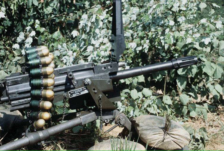
18 Report Date: 17 Feb 2012 Summary Report for Individual Task Unload an MK 19 Grenade Machine Gun Status: Approved DISTRIBUTION RESTRICTION: Distribution authorized to U.S. Government agencies only DESTRUCTION NOTICE: Destroy by any method that will prevent disclosure of contents or reconstruction of the document. Condition: As a gunner, given a MK 19 grenade machine gun, mounted on a tripod or vehicle, loaded with linked 40mm grenade ammunition, and a 40mm ammunition can. You have been directed to unload the weapon. Some iterations of this task should be performed in MOPP. Standard: Place the safety switch to safe, remove the case catch bag, charge the weapon, remove all live rounds or spent cases from the bolt, open the top cover, remove linked rounds from the feeder, return the bolt to the forward position and place the safety switch in the S position. Special Condition: None Special Standards: None Special Equipment: None Safety Level: Low MOPP: Sometimes Cue: None Task Statements None Warning None CAUTION None Remarks: None Notes: None Performance Steps 1. Place the safety switch to S (SAFE). 2. Remove the case catch bag, if applicable. 3. Charge the weapon.
19 Warning Do not use a bayonet to remove an empty case or live round. A cleaning rod should be used. 4. Remove live round or spent case from the bolt, if present. a. Insert the tip of a cleaning rod through the receiver rail as close to the bolt face as possible. b. Place the tip of the cleaning rod on top of the live round or spent case, as close to the bolt face as possible. c. Position one hand beneath the weapon to catch the round as it falls out. d. Force the live round off the bolt face and out the bottom of the gun by pushing down on the cleaning rod. e. Catch the live round as it falls out. f. Dispose of the live round as per unit SOP. Note: Do not reuse a live round that has been cycled through the weapon and removed from the bolt. 5. Open the top cover assembly. 6. Remove linked rounds from the feeder, if present. a. Reach beneath the feed tray with one hand. b. Press and hold both the primary and secondary positioning pawls. c. Slide the linked rounds out of the feeder and out the feed throat. d. Return the linked rounds to the ammunition can. 7. Return the bolt to the forward position. a. Place the safety switch in the fire (F) position. b. Hold one charger handle to the rear. c. Ride the bolt forward by squeezing the trigger and easing the bolt forward. d. Ensure both charging handles are forward and up position. 8. Place the safety switch in the S position. (Asterisks indicate a leader performance step.) Evaluation Preparation: SETUP: Provide the Soldier with the equipment and/or materials described in the conditions statement. BRIEF THE SOLDIER: Explain what is expected of the Soldier by reviewing the task standards. Stress to the Soldier the importance of observing all cautions, warnings, and dangers to avoid injury to personnel and, if applicable, damage to equipment.
20 PERFORMANCE MEASURES GO NO-GO N/A 1. Placed the safety switch to S (SAFE). 2. Removed the case catch bag, if applicable. 3. Charged the weapon. 4. Removed live round or spent case from the bolt, if present. 5. Opened the top cover assembly. 6. Removed linked rounds from the feeder, if present. 7. Returned the bolt to the forward position. 8. Placed the safety switch in the S position. Supporting Reference(s): Step Reference Reference Name Required Primary FM MK 19, 40-MM GRENADE No No MACHINE GUN, MOD 3 TM OPERATORS MANUAL FOR No No MACHINE GUN, 40-MM, MK 19, MOD 3 (NSN ) (EIC: 4AE) {TM 08521A-10/1A;TO 11W SW 363 C3 MMM 010} Environment: Environmental protection is not just the law but the right thing to do. It is a continual process and starts with deliberate planning. Always, be alert to ways to protect our environment during training and missions. In doing so, you will contribute to the sustainment of our training resources while protecting people and the environment form harmful effects. Safety: In a training environment, leaders must perform a risk assessment in accordance with FM 5-19, Composite Risk Management. Leaders will complete a DA Form 7566 COMPOSITE RISK MANAGEMENT WORKSHEET during the planning and completion of each task and sub-task by assessing mission, enemy, terrain and weather, troops and support available-time available and civil considerations, (METT-TC). Note: During MOPP training, leaders must ensure personnel are monitored for potential heat injury. Local policies and procedures must be followed during times of increased heat category in order to avoid heat related injury. Consider the MOPP work/rest cycles and water replacement guidelines IAW FM , NBC Protection, FM , CBRN Decontamination. Everyone is responsible for safety. A thorough risk assessment must be completed prior to every mission or operation. Prerequisite Individual Tasks: None Supporting Individual Tasks: Task Number Title Proponent Status Correct Malfunctions of an MK Infantry (Individual) Analysis Grenade Machine Gun Maintain an MK19 Grenade Machine Infantry (Individual) Approved Gun, Tripod, and Ammunition Load an MK 19 Grenade Machine Gun Infantry (Individual) Approved Supported Individual Tasks :
21 Perform a Function Check on a MK 19 Grenade Machine Gun Mount an AN/PAS-13 Thermal Weapon Sight (TWS) on a MK mm Grenade Machine Gun Remove a Primary Weapon from Reconnaissance Vehicle (RV) or Fire Support Vehicle (FSV) Correct Malfunctions of an MK 19 Grenade Machine Gun Infantry (Individual) Infantry (Individual) Armor (Individual) Infantry (Individual) Analysis Approved Approved Analysis Interactive Multimedia Instruction:
22 Report Date: 17 Feb 2012 Summary Report for Individual Task Load an MK 19 Grenade Machine Gun Status: Approved DISTRIBUTION RESTRICTION: Distribution authorized to U.S. Government agencies only DESTRUCTION NOTICE: Destroy by any method that will prevent disclosure of contents or reconstruction of the document Condition: As a gunner, given a MK19 grenade machine gun, mounted on a tripod or vehicle, with linked 40mm grenade ammunition, and 40mm ammunition can. You have been directed to load the weapon. Some iterations of this task should be performed in MOPP. Standard: Clear the weapon, attach feed throat to feeder, insert round, load round and place weapon on safe. Special Condition: None Special Standards: None Special Equipment: None Safety Level: Low MOPP: Sometimes Task Statements Cue: None Warning Before performing any procedure, ensure the weapon is clear of any ammunition. Use only ammunition authorized for use with the MK19 machine gun. Do not allow the top cover to slam shut from raised position when loading. Hand injury or equipment damage may result. Remarks: None Notes: None CAUTION None
23 Performance Steps 1. Clear the weapon. Warning While loading, the bolt must be forward. If the bolt is not forward, take gun off SAFE and ease charger handles forward. Do not let top cover slam shut from open position. 2. Attach feed throat to feeder. Note: The feed throat prevents the linked rounds from twisting as they pass from the ammunition can into the MK19 receiver during firing. The major contributor to the MK19 jamming is ammo being separated by twisting the ammo belt, causing the ammo link to become misaligned. After the ammo belt has been separated, the ammo link should be aligned evenly and touching the copper band all around the ammo. a. Squeeze the spring-loaded pins on feed throat. b. Insert into the slots on both sides of the feeder. 3. Insert a round. Note: When using a vehicle mount, attach ammunition can bracket and can. When using a ground tripod mount, feed the ammunition directly from the can. a. Open the top cover assembly. b. Insert the round through the feed throat (female first) into the feeder. c. Push the round across the first set of feeder pawls. d. Ensure the round is straight and firmly seated against the bolt. e. Push the secondary drive lever to the right. Note: This moves the feed slide to the left. f. Close the top cover assembly. 4. Load the first round to the fully-loaded position. a. Charge the weapon. (1) Lower both charger handles. (2) Pull both charger handles to the rear ensuring the bolt locks to the rear. (3) Return both charger handles to the forward position. b. Place safety switch in FIRE position. c. Squeeze the trigger allowing the bolt to slam forward. d. Rotate both charger handles down. e. Pull both charging handles to the rear. Note: This moves the round down the curved rail on the vertical cam assembly. It forces the round down the bolt face out of the extractors into the bolt fingers (position for firing - full load). f. Return both charging handle to the forward and up position. 5. Place safety switch in SAFE position.
24 Note: The weapon is now ready to fire. (Asterisks indicate a leader performance step.) Evaluation Preparation: SETUP: Provide the Soldier with the equipment and/or materials described in the conditions statement. BRIEF THE SOLDIER: Explain what is expected of the Soldier by reviewing the task standards. Stress to the Soldier the importance of observing all cautions, warnings, and dangers to avoid injury to personnel and, if applicable, damage to equipment. PERFORMANCE MEASURES GO NO-GO N/A 1. Cleared the weapon. 2. Attached feed throat to feeder. 3. Inserted a round. 4. Loaded the first round to the fully-loaded position. 5. Placed the safety switch on SAFE. Supporting Reference(s): Step Number Reference ID Reference Name Required Primary FM MK 19, 40-MM GRENADE No No MACHINE GUN, MOD 3 TM OPERATORS MANUAL FOR No No 10 MACHINE GUN, 40-MM, MK 19, MOD 3 (NSN ) (EIC: 4AE) {TM 08521A 10/1A TO 11W2 5 Environment: Environmental protection is not just the law but the right thing to do. It is a continual process and starts with deliberate planning. Always, be alert to ways to protect our environment during training and missions. In doing so, you will contribute to the sustainment of our training resources while protecting people and the environment form harmful effects. Safety: In a training environment, leaders must perform a risk assessment in accordance with FM 5-19, Composite Risk Management. Leaders will complete a DA Form 7566 COMPOSITE RISK MANAGEMENT WORKSHEET during the planning and completion of each task and sub-task by assessing mission, enemy, terrain and weather, troops and support available-time available and civil considerations, (METT-TC). Note: During MOPP training, leaders must ensure personnel are monitored for potential heat injury. Local policies and procedures must be followed during times of increased heat category in order to avoid heat related injury. Consider the MOPP work/rest cycles and water replacement guidelines IAW FM , NBC Protection, FM , CBRN Decontamination. Everyone is responsible for safety. A thorough risk assessment must be completed prior to every mission or operation. Prerequisite Individual Tasks: None
25 Supporting Individual Tasks: Task Number Title Proponent Status Correct Malfunctions of an MK 19 Grenade Machine Gun Infantry (Individual) Analysis Mount an MK19 Grenade Machine Gun on a Vehicle Mount an MK 19 Grenade Machine Gun on an M3 Tripod Supported Individual Tasks: Infantry (Individual) Analysis Infantry (Individual) Analysis Task Number Title Proponent Status Remove a Primary Weapon Armor (Individual) Approved from Reconnaissance Vehicle (RV) or Fire Support Vehicle (FSV) Unload an MK 19 Grenade Infantry (Individual) Reviewed Zero an MK 19 Grenade Machine Infantry (Individual) Approved Zero a Night Vision Sight, Infantry (Individual) Analysis AN/TVS-5, to an MK 19 Grenade MPerform hi a G Function Check on a MK071 - Infantry (Individual) Analysis 19 Interactive Multimedia Instruction:
26 Report Date: 23 Feb 2012 Summary Report for Individual Task Correct Malfunctions of an MK 19 Grenade Machine Gun Status: Approved DISTRIBUTION RESTRICTION: Distribution authorized to U.S. Government agencies only DESTRUCTION NOTICE: Destroy by any method that will prevent disclosure of contents or reconstruction of the document Condition: As a gunner, given a MK 19 grenade machine gun, that has malfunctioned while firing. You have been directed to correct the malfunctions on the MK 19 grenade machine gun. Some iterations of this task should be performed in MOPP. Standard: Take immediate actions to correct a failure to fire, a runaway weapon, and perform remedial actions on the MK 19 grenade machine gun. Report deficiencies not correctable at operator level to supervisor. Special Condition: None Special Standards: None Special Equipment: None Safety Level: Low MOPP: Sometimes Cue: None Task Statements Warning Remarks: None Notes: None None CAUTION None Performance Steps 1. Take immediate action to correct a failure to fire. Note: Immediate action is only performed once for a stoppage. If any immediate actions cannot be fully completed; such as the bolt will not pull to the rear, nothing ejects, or the charger handles will not lock in the up position, remedial action is performed. In a noncombat environment, immediate area should be cleared of personnel and an assistant should be used to catch any round that is ejected upon pulling the charger handles to the rear. The key words pull, observe, push, squeeze (POPS) will help you remember the steps for immediate action.
27 a. Pull the charger handles to the rear. b. Observe the ejection port to see if a case, link, or round ejects. c. Push the charger handles forward to the up position. d. Squeeze the trigger. Warning Never try to break the ammo belt with your hands. Injury could result. 2. Take immediate action to secure a runaway weapon. Note: A runaway weapon or uncontrolled fire is when the weapon continues to fire after the trigger has been released. a. Keep the weapon oriented on the target area. b. Allow all remaining rounds in the loaded belt to fire or stop the ammunition feed by pressing the charger handle locks and lowering the charging handle(s) to disrupt the cycle of firing. c. Place the gun on S (SAFE). d. Perform corrective action on a runaway weapon. (1) Wait 5 minutes to allow the barrel to cool. (2) Load the MK 19. (3) Engage targets. (4) Take remedial action on the MK 19 if the uncontrolled firing continues. 3. Perform remedial action to correct a failure to fire. Note: Remedial action is needed if, after applying immediate action it did not correct the failure to fire. a. Place the safety switch to the S (SAFE) position. b. Keep the weapon oriented on the target area. c. Remove the case catch bag, if applicable. d. Charge the weapon. (1) Lower both charger handles. (2) Pull both charger handles to the rear ensuring the bolt locks to the rear. Note: If bolt will not lock to the rear then the gunner must hold the bolt to the rear as the assistant gunner removes the live round or spent case, if present. (3) Return both charger handles to the forward position. (4) Rotate only one charger handle up. e. Remove live round or spent case from the bolt, if present. (1) Insert the tip of a cleaning rod through the receiver rail as close to the bolt face as possible. (2) Place the tip of the cleaning rod on top of the live round or spent case, as close to the bolt face as possible. (3) Position one hand beneath the weapon to catch the round as it falls out. (4) Force the live round off the bolt face and out the bottom of the gun by pushing down on the cleaning rod.
28 (5) Catch the live round as it falls out. (6) Dispose of the live round as per unit standard operating procedure (SOP). Note: Do not reuse a live round that has been cycled through the weapon and removed from the bolt. f. Inspect removed round. (1) Check the primer to see if it is indented or not. (2) Proceed to step, load the MK19, if the primer is indented, as this indicates bad round. Note: Dispose of bad round IAW unit policies. (3) Continue remedial action, after recording the MK 19 has a bad firing pin, if the primer is not indented. If the bolt jams during firing, do not let the bolt slam forward as the top cover is being opened because a round could fire. g. Open the top cover assembly. h. Remove linked rounds and any loose links from the feeder, if present. (1) Reach beneath the feed tray with one hand. (2) Press and hold both the primary and secondary positioning pawls. (3) Slide the linked rounds out of the feeder and out the feed throat. (4) Return the linked rounds to the ammunition can. i. Return the bolt to the forward position. (1) Place the safety switch on F (FIRE). (2) Hold one charger handle to the rear. (3) Ride the bolt forward by squeezing the trigger and easing the bolt forward. (4) Ensure both charger handles are forward and up position. (5) Place the safety switch on S (SAFE). j. Check for an obstructed bore, if suspected. Note: Indicators of a bore obstruction are: Warning (1) A muffled sound of round firing; (2) Excess smoke out of the chamber area; or (3) Excess debris/gases below gun). The preferred method for checking the bore is by running the bore obstruction detector from the top of the receiver through the barrel until it protrudes from the muzzle. However, the bore obstruction detector may also be feed from the bottom of the receiver. The bolt must be to the rear to use the bore obstruction detector from the bottom. Warning Do not transport weapon with projectile lodged in bore. (4) Conduct deliberate check for an obstructed bore.
29 (a) Remove the backplate pin, bolt, and backplate assembly, vertical cam assembly, and primary drive lever. (b) Observe the bore for any type of bore obstruction. (5) Conduct rapid check for an obstructed bore. (a) Insert the bore obstruction detector (weighted end first) into the chamber end of the barrel. (b) Snake the bore obstruction detector into the barrel. Note: If the cable stops feeding, pull it back, and push it forward again. If the cable can't be pushed forward any further, you have a bore obstruction. Warning WARNING Only trained and qualified personnel should engage in the removal and recovery of the round. CAUTION Do not use round removal tool to remove a spent case lodged in the bore. Damage to barrel and tool will occur. The round removal tool is used to extract a complete round or a separated round that is lodged in the barrel. k. Remove bore obstruction, if present, using the round removal tool. (1) Place round removal tool collar over end of flash suppressor. (2) Screw five cap screws into slots of the suppressor. (3) Attach either end of handle to the end of the threaded rod. (4) Screw threaded rod into barrel. (5) Push out bore obstruction. (6) Catch projectile with both hands as it is forced from the barrel. (7) Carefully dispose of live projectile as per unit SOP. l. Inspect linked ammunition belt. (1) Check that the link band is even and adjacent to copper band all around ammo. (2) Check that the female link is positioned to be loaded first. Warning WARNING Do not re-link or fire any ammunition that has been cycled through the weapon. (3) Remove the first round from belt if there is any indication of a bad link. m. Load the MK 19, if the MK 19 has no uncorrected faults. n. Attempt to fire the MK 19, if the MK 19 has no uncorrected faults. 4. Report deficiencies not correctable at the operator level to the supervisor. a. Turn-in the MK 19 for service. b. Record any identified fault that cannot be corrected. (Asterisks indicate a leader performance step.)
30 Evaluation Preparation: SETUP: Provide the Soldier with the equipment and/or materials described in the conditions statement. BRIEF THE SOLDIER: Explain what is expected of the Soldier by reviewing the task standards. Stress to the Soldier the importance of observing all cautions, warnings, and dangers to avoid injury to personnel and, if applicable, damage to equipment. PERFORMANCE MEASURES GO NO-GO N/A 1. Took immediate action to correct a failure to fire. 2. Took immediate action to secure a runaway weapon. 3. Performed remedial action to correct a failure to fire. 4. Reported deficiencies not correctable at operator level to the Supporting Reference(s): Step Number Reference ID Reference Name Required Primary FM MK 19, 40-MM GRENADE No No MACHINE GUN, MOD 3 TM OPERATORS MANUAL FOR No No 10 MACHINE GUN, 40-MM, MK 19, MOD 3 (NSN ) (EIC: 4AE) {TM 08521A 10/1A TO 11W2 5 Environment: Environmental protection is not just the law but the right thing to do. It is a continual process and starts with deliberate planning. Always, be alert to ways to protect our environment during training and missions. In doing so, you will contribute to the sustainment of our training resources while protecting people and the environment form harmful effects. Safety: In a training environment, leaders must perform a risk assessment in accordance with FM 5-19, Composite Risk Management. Leaders will complete a DA Form 7566 COMPOSITE RISK MANAGEMENT WORKSHEET during the planning and completion of each task and sub-task by assessing mission, enemy, terrain and weather, troops and support available-time available and civil considerations, (METT-TC). Note: During MOPP training, leaders must ensure personnel are monitored for potential heat injury. Local policies and procedures must be followed during times of increased heat category in order to avoid heat related injury. Consider the MOPP work/rest cycles and water replacement guidelines IAW FM , NBC Protection, FM , CBRN Decontamination. Everyone is responsible for safety. A thorough risk assessment must be completed prior to every mission or operation. Prerequisite Individual Tasks: None Supporting Individual Tasks: Task Number Title Proponent Status Maintain an MK19 Grenade Machine Infantry (Individual) Approved Engage Targets with an MK 19 Grenade Infantry (Individual) Analysis Unload an MK 19 Grenade Infantry (Individual) Approved
31 Engage Targets with a MK Infantry (Individual) Approved Grenade Machine Gun using an AN/PAS-13 Supported Individual Tasks : Task Number Title Proponent Status Load an MK 19 Grenade Machine Infantry (Individual) Approved Unload an MK 19 Grenade Infantry (Individual) Approved Remove a Primary Weapon Armor (Individual) Approved from Reconnaissance Vehicle (RV) or Fire Support Vehicle (FSV) Perform a Function Check on a MK071 - Infantry (Individual) Approved 19 Interactive Multimedia Instruction: / /index.html
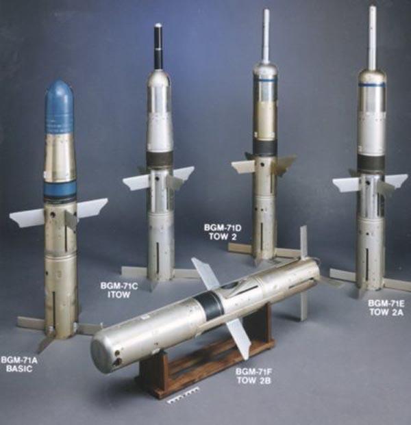
32 Report Date: 17 Apr 2012 Summary Report for Individual Task Prepare a M98-series Javelin for Firing Status: Approved DISTRIBUTION RESTRICTION: Distribution authorized to U.S. Government agencies only DESTRUCTION NOTICE: Destroy by any method that will prevent disclosure of contents or reconstruction of the document. Condition: As a gunner, given an M98A1 or M98A2 Javelin, a command launch unit (CLU), a target, and day/night vision sight (NVS). You have been directed to prepare the Javelin for firing. Some iterations of this task should be performed in MOPP. Standard: Inspect the major components, prepare the command launch unit (CLU), assemble the Javelin, and power up the CLU. Special Condition: None Special Standards: None Special Equipment: None Safety Level: Low MOPP: Sometimes Cue: None Task Statements WARNING The BA-5590/U battery contains pressurized lithium sulfur dioxide gas. It is highly toxic. Do not handle the battery in any way which may cause the battery to rupture. Remarks: None Warning CAUTION None Notes: The Javelin is a medium range, man-portable, recoilless, antitank assault weapon and is capable of defeating current and projected enemy armor, and hovering enemy helicopters. The Javelin can be used during the day, night, or degraded weather conditions. The Javelin is made up of a onetime expendable round and a CLU. Performance Steps 1. Inspect major components of the M98-series javelin. a. Inspect CLU and round surfaces for heavy coating of dirt or mud. (1) Dust if slightly dirty. (2) Rinse area with clean water if very dirty. (3) Clean all metal parts on CLU and round with clean dry cloth. (4) Clean rubber or synthetic parts using water.
33 (5) Dry all parts with clean dry cloth. b. Inspect daysight and night vision sight (NVS) lens. CAUTION Do not touch the lens with your hands or fingers. Wash hands before cleaning lenses. Natural oils produced by the skin are corrosive to lens coatings. (1) Open daysight and NVS lens covers. CAUTION Do not scrub lens surface. Optical coating may be damaged. (2) Pour clean water, repeatedly over lens until all dirt or mud is removed. (3) Dry lens with clean dry cloth. (4) Secure a lens cleaning paper. (5) Wipe the lens. (a) Begin at center of lens. (b) Apply light pressure with fingers. (c) Wipe in an expanding circular motion (spiral) to edge of lens. (6) Close daysight and NVS lens covers. c. Inspect the round interface connectors for dirt or mud. (1) Dust if slightly dirty. (2) Rinse area with clean water if very dirty. (3) Dry all wet parts with clean dry cloth. 2. Prepare the CLU. a. Ensure the power switch is in the OFF position. b. Install the CLU battery. (1) Release the bail from the battery cover. (2) Raise the battery cover. (3) Clean the battery compartment of dirt or loose objects. (4) Remove the white tape from the electrical connector. (5) Shake the battery. Note: This ensures the battery has not developed an oxidation layer between cells. (6) Slide battery into battery compartment, making sure battery engages with battery interface connector. (7) Replace the battery compartment cover. (8) Secure the bail to the battery cover. 3. Assemble the Javelin. a. Place the round on the ground with the flat sides of the end caps down and latch assembly facing up. b. Kneel on the left side of the round, at the forward end, facing forward.
34 c. Remove the protective covers from the CLU interface connectors. (1) Pull on tab of lanyard to snug protective cover against side of the round. (2) Position protective cover so that no interference will exist when round is connected. d. Remove the protective covers from the round interface connectors. (1) Pull on tab of lanyard to snug protective cover against side of the CLU. (2) Position protective cover so that no interference will exist when CLU is connected. e. Place round interface bracket in round hooks. f. Engage CLU and round interface connectors by sliding forward and press down on CLU.\ Note: Round and CLU are connected correctly when latch release snaps into place. g. Ensure that the round and CLU are connected. (1) Rock the CLU from side-to-side. (2) Pick up the Javelin. h. Remove the forward end cap. (1) Remove the locking pin by pulling straight up on the wire rope. (2) Turn the forward end cap latch release counterclockwise. Note: If the forward end cap does not come off, press manual release button to relieve pressure. CAUTION With forward end cap removed, seeker dome is exposed. Use caution when tipping end of round down to avoid foreign material (rocks, mud, etc.) coming in contact with seeker dome. (3) Remove forward end cap by lifting the Javelin way from the forward end cap. i. Position open end of round on forward end cap. 4. Power up the CLU. a. Open daysight and NVS lens covers on CLU. b. Set power switch to the NIGHT position. Note: The CLU has four modes of operation: Off, Day, Night (IR Surveillance) and test. c. Verify the CLU indicators are lit. Note: CLU indicators may flash on and off during initial power up. This indicates that the battery needs time to warm up before CLU can power up properly. d. Perform battery warm-up procedures, as required. (1) Turn the power switch to the DAY position for 30 to 60 seconds. (2) Turn the power switch to the OFF position, then back to the NIGHT position. e. Repeat warm-up if indicators continue to flash. f. Adjust diopter adjust ring for best clarity of CLU display. Note: The Javelin is now prepared to engage a target.
35 (Asterisks indicate a leader performance step.) Evaluation Preparation: SETUP: Provide the Soldier with the equipment and/or materials described in the conditions statement. BRIEF THE SOLDIER: Tell the Soldier what is expected by reviewing the task standards. Stress to the Soldier the importance of observing all cautions, warnings, and dangers to avoid injury to personnel and, if applicable, damage to equipment. PERFORMANCE MEASURES GO NO-GO N/A 1. Inspect major components of the M98-series Javelin. 2. Prepared the CLU. 3. Assembled the Javelin. 4. Powered up the CLU. Supporting Reference(s): Step Number Reference ID Reference Name Required Primary FM JAVELIN - CLOSE COMBAT No Yes MISSILE SYSTEM, MEDIUM TM Operator s Manual for the Javelin No Yes Weapon System M98A2 (NSN: )(EIC: NA){Marine TM C OPERATOR'S MANUAL FOR No Yes 10 THE JAVELIN WEAPON SYSTEM M98A1 Environment: Environmental protection is not just the law but the right thing to do. It is a continual process and starts with deliberate planning. Always be alert to ways to protect our environment during training and missions. In doing so, you will contribute to the sustainment of our training resources while protecting people and the environment from harmful effects. Refer to FM Environmental Considerations and GTA ENVIRONMENTAL-RELATED RISK ASSESSMENT Safety: In a training environment, leaders must perform a risk assessment in accordance with FM 5-19, Composite Risk Management. Leaders will complete a DA Form 7566 COMPOSITE RISK MANAGEMENT WORKSHEET during the planning and completion of each task and sub-task by assessing mission, enemy, terrain and weather, troops and support available-time available and civil considerations, (METT-TC). Note: During MOPP training, leaders must ensure personnel are monitored for potential heat injury. Local policies and procedures must be followed during times of increased heat category in order to avoid heat related injury. Consider the MOPP work/rest cycles and water replacement guidelines IAW FM , NBC Protection, FM , CBRN Decontamination. In a training environment, leaders must perform a risk assessment in accordance with FM 5-19, Composite Risk Management. Leaders will complete a DA Form 7566 COMPOSITE RISK MANAGEMENT WORKSHEET during the planning and completion of each task and sub-task by assessing mission, enemy, terrain and weather, troops and support available-time available and civil considerations, (METT-TC). Note: During MOPP training, leaders must ensure personnel are monitored for potential heat injury. Local policies and procedures must be followed
36 during times of increased heat category in order to avoid heat related injury. Consider the MOPP work/rest cycles and water replacement guidelines IAW FM , NBC Protection, FM , CBRN Decontamination. Prerequisite Individual Tasks: None Supporting Individual Tasks: Task Number Title Proponent Status Restore a M98-series Javelin to Carrying Infantry (Individual) Reviewed Construct a Fighting Position for a Infantry (Individual) Approved Maintain a Javelin Infantry (Individual) Analysis React to Javelin that Fails to Fire Infantry (Individual) Reviewed Engage Targets with a Javelin Infantry (Individual) Analysis Supported Individual Tasks: Task Number Title Proponent Status Engage Targets with a Javelin Infantry (Individual) Analysis React to Javelin that Fails to Fire Infantry (Individual) Reviewed Restore a M98-series Javelin to Carrying Infantry (Individual) Reviewed
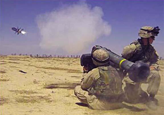
37 Report Date: 11 Jul 2012 Summary Report for Individual Task Engage Targets with a Javelin BST Status: Approved DISTRIBUTION RESTRICTION: Distribution authorized to U.S. Government agencies only DESTRUCTION NOTICE: Destroy by any method that will prevent disclosure of contents or reconstruction of the document Condition: As a gunner given a M98-series Javelin prepared for firing, ear plugs, a detected stationary or moving target at an engageable range. You have directed to engage the target. Some iterations of this task should be performed in MOPP. Standard: Assume an appropriate firing position, acquire the target using the command & launch unit (CLU), determine target engageability, identify target, activate the seeker, obtain seeker lockon, and launch the missile. Use appropriate engagement techniques to ensure each target is hit. Special Condition: None Special Standards: None Special Equipment: Javelin basic skills trainer (BST) Safety Level: Low MOPP: Sometimes Cue: None Task Statements WARNING Keep body at a 30 degree angle away from the round when launching a missile from the prone position. Injury may occur if body is extended into backblast area. Remarks: None Notes: None Warning CAUTION None
38 Performance Steps 1. Assume an appropriate firing position. Note: Your position should protect you from enemy fire and observation, yet allow you to place effective fire on your target. Your physical position may vary from a fixed location to a temporary location during movement. a. Select a physical position that has appropriate cover and concealment. b. Select the most appropriate firing position (Figure 1). Figure 1. Javelin Firing Positions. c. Check the overhead flight path between the target and the firing position. d. Ensure the forward end cap is on the ground out of the backblast area. 2. Acquire the target using the CLU. a. Set the SGT SEL (sight select) switch to WFOV or NFOV. Note: WFOV is usually best to initially acquire a target, while NFOV is best to track, identify, and engage the target. b. Adjust the CLU for best view. (1) Press the FOCUS switch up-and-down to adjust the infrared video. (2) Adjust the contrast by moving the GATE ADJ/CTRS & BRT switch left or right. (3) Adjust the brightness is by moving the GATE ADJ/CTRS & BRT switch up or down.
.")
, WFOV target in-range (center), NFOV target out-ofrange (right) (1) Move the stadia lines to the target, keeping the target between the stadia lines.")
39 Heavy Weapons Leader Course Read Ahead Packet and Prerequisite c.scan for target. 3. Determine target engageability. Note: The gunner uses the stadia in CLU display to determine if a target is in - range of the Javelin missile. a. Determine target engageability using full stadia method (Figure 2). Note: The process is the same for both WFOV and NFOV. However in NFOV the upper reticle line extends between the stadia lines but is ignored for measuring purposes. Figure 2. WFOV Stadia (left), WFOV target in-range (center), NFOV target out-ofrange (right) (1) Move the stadia lines to the target, keeping the target between the stadia lines. (2) Place one of the stadia on one edge of the target. (3) Determine the target is in range if the opposite edge of the target touches or exceeds the other stadia. b. Determine target engageability using half stadia method (Figure 3). Note: The process is the same for both WFOV and NFOV. However in NFOV the upper reticle line extends between the stadia lines and can be used for measuring purposes. Figure 3. NFOV Stadia (left), WFOV target in-range (center), NFOV target out-ofrange (right) (1) Move the stadia to the target, keeping the target between the stadia lines.
40 Heavy Weapons Leader Course Read Ahead Packet and Prerequisite (2) Place one of the stadia lines on one edge of the target. (3) Visualize a line running halfway between the two WFOV stadia lines (use the reticle line if in NFOV. (4) Determine the target is in range if the opposite edge of the target touches or exceeds the visualized line of reticle line. 4. Identify target. a. Threat b. Non-Threat 5. Activate the seeker. Note: The battery coolant unit (BCU) has a limited battery life. Once the BCU is activated, the gunner will have approximately 4 minutes to launch the missile. The BATTERY COOLANT UNIT LOW indicator is located at the bottom of the CLU display at the far left. During system operation, after seeker activation, the indicator will flash to indicate the BCU has approximately 30 seconds (or more, depending on the ambient temperature) of operating time remaining. When it lights solid, the BCU is spent, the CLU reverts to the last CLU FOV, all missile functions stop, and the missile cannot be launched. a. Re-center target in the day FOV. b. Lift the seeker trigger guard on the left handgrip. c. Squeeze the seeker trigger and wait for the SEEK and battery indicators to light. Note: The NFOV indicator will remain lit. Remember to listen for the BCU squib sound when the seeker is activated. Once the BCU is activated, the gunner will have approximately 4 minutes to launch the missile. The BCU indicator flashes when the BCU has approximately 30 seconds of operating time remaining. d. Release seeker trigger after the SEEK and battery indicators are lit. e. Observe the activation of the seeker. Note: The activation of the seeker takes approximately seconds, indicated by the NFOV and battery indicators going out and the TOP indicator and flashing track gates coming on. f. Select direct attack mode, as required. Note: Top attack is the default attack mode for the missile. Attack mode can be changed between top attack and direct attack anytime before seeker lock by pressing ATTK SEL switch. (1) Press ATTK SEL switch. (2) Observe that DIR indicator lights and TOP indicator is off. 6. Activate seeker lock-on.
 Press GATE ADJ/CTRS & BRT switch up or down to open or closes track gates vertically.")
41 Heavy Weapons Leader Course Read Ahead Packet and Prerequisite a. Position track gates around outer edge of target by pressing gate ADJ/CTRS & BRT switch, up, down, right or left (Figure 4). Figure 4. Track Gates around edge of target. (1) Press GATE ADJ/CTRS & BRT switch up or down to open or closes track gates vertically. (2) Press GATE ADJ/CTRS & BRT switch left or right to open or close track gates horizontally. b. Squeeze and hold the seeker trigger. c. Observe for seeker lock-on indicators. (1) Observe for track gates to stop flashing. (2) Observe for appearance of solid crosshairs on CLU display. d. Break target lock if wrong target is locked on or lock-on quality is poor. (1) Release the seeker trigger. (2) Return to step 6, Obtain seeker lock-on. e. Continue to squeeze and hold the seeker trigger. Warning WARNING Avoid looking down-range during initial missile launch without proper protection. Debris from the rocket motor may cause serious injury. Do not launch missile at targets closer than minimum effective range, 65 meters (211 feet). Warhead will not be armed and a dud will result. 7. Launch the missile. a. Center crosshairs on target. b. Squeeze and hold fire trigger until missile launches. c. Release fire and seeker triggers when missile launches. Note: The CLU display will return to FOV used to activate the seeker and the associated FOV indicator will be on if the missile launches. d. Place Javelin on the ground with CLU handgrips facing up. e. Press latch release and disconnect CLU from empty launch tube assembly (LTA).
Summary Report for Individual Task M-1364 Operate Vehicle with Standard, Automatic/Semiautomatic Transmission Status: Approved
 Summary Report for Individual Task 551-88M-1364 Operate Vehicle with Standard, Automatic/Semiautomatic Transmission Status: Approved Report Date: 05 Dec 2014 Distribution Restriction: Approved for public
Summary Report for Individual Task H-1537 Operate ATLAS Rough Terrain Forklift Without a Load Status: Approved
 Report Date: 21 May 2014 Summary Report for Individual Task 551-88H-1537 Operate ATLAS Rough Terrain Forklift Without a Load Status: Approved Distribution Restriction: Approved for public release; distribution
Summary Report for Individual Task M-1314 Perform Coupling Operations Status: Approved
 Report Date: 03 Mar 2015 Summary Report for Individual Task 551-88M-1314 Perform Coupling Operations Status: Approved Distribution Restriction: Approved for public release; distribution is unlimited. Destruction
Summary Report for Individual Task M-1501 Perform Load/Unload Operations in Automatic Mode Status: Approved
 Report Date: 05 Dec 2014 Summary Report for Individual Task 551-88M-1501 Perform Load/Unload Operations in Automatic Mode Status: Approved Distribution Restriction: Approved for public release; distribution
Summary Report for Individual Task MANAGE AIRCRAFT STORAGE PROGRAM Status: Approved
 Report Date: 13 Jun 2014 Summary Report for Individual Task 552-101-1876 MANAGE AIRCRAFT STORAGE PROGRAM Status: Approved Distribution Restriction: Approved for public release; distribution is unlimited.
Summary Report for Individual Task L-3048 Troubleshoot a Purifier Status: Approved
 Report Date: 30 Apr 2012 Summary Report for Individual Task 551-88L-3048 Troubleshoot a Purifier Status: Approved DISTRIBUTION RESTRICTION: Approved for public release; distribution is unlimited. DESTRUCTION
Summary Report for Individual Task M-1661 Perform Wheeled Vehicle Hasty/Self-Recovery on a Wheeled Vehicle Status: Approved
 Summary Report for Individual Task 551-88M-1661 Perform Wheeled Vehicle Hasty/Self-Recovery on a Wheeled Vehicle Status: Approved Report Date: 12 Jan 2015 Distribution Restriction: Approved for public
Summary Report for Individual Task M-1656 Conduct Refueling Operations using Tactical Refueling Vehicles Status: Approved
 Summary Report for Individual Task 551-88M-1656 Conduct Refueling Operations using Tactical Refueling Vehicles Status: Approved Report Date: 05 Dec 2014 Distribution Restriction: Approved for public release;
Summary Report for Individual Task M-2355 Operate Vehicle in Inclement Weather Conditions Status: Approved
 Report Date: 24 Jul 2014 Summary Report for Individual Task 551-88M-2355 Operate Vehicle in Inclement Weather Conditions Status: Approved Distribution Restriction: Approved for public release; distribution
Figure 3-1. MK 67 MOD 7 gun cradle.
 CHAPTER 3 GROUND AND VEHICLE MOUNTS The MK 19 is used in either the ground- or vehicle-mount mode. The most often used ground mount is the M3 tripod. The M3 serves as a stable platform when the weapon
ARDEC Rapid Design Projects for Field Support Part 1
 ARDEC Rapid Design Projects for Field Support Part 1 L-Bracket for use with M240B Medium Machine Guns on HMMWVs with Gunner s Protection Shield (NSN 2510-01-498-4996) Michael Narus Robert Mulfinger Anthony
Summary Report for Individual Task M-1411 Perform Tiedown Procedures Status: Approved
 Report Date: 05 Dec 2014 Summary Report for Individual Task 551-88M-1411 Perform Tiedown Procedures Status: Approved Distribution Restriction: Approved for public release; distribution is unlimited. Destruction
BROWNING.50 M2 MACHINE GUN, ASSEMBLY
 Parts Catalog BROWNING.50 M2 MACHINE GUN, ASSEMBLY Page 1 DEC 2016 PCOOWM2HB phone: 440.285.3481 fax: 440.286.8571 web: ohioordnanceworks.com OOW M2 Configurations M2 HB SKU: 7265636 M2 QCB SKU: M2A1-100E
TECHNICAL MANUAL UNIT AND DIRECT MAINTENANCE MANUAL INCLUDING REPAIR PARTS AND SPECIAL TOOLS LIST M60D, 7.62 MM, MACHINE GUN
 TECHNICAL MANUAL UNIT AND DIRECT MAINTENANCE MANUAL INCLUDING REPAIR PARTS AND SPECIAL TOOLS LIST M60D, 7.6 MM, MACHINE GUN U.S. ORDNANCE M60D PROVEN UNDER FIRE WARNING The M60D Series Machine Guns should
CHAPTER 1 INTRODUCTION
 CHAPTER 1 INTRODUCTION The procedures and methods used in Army machine gun marksmanship are based on the concept that soldiers must be skilled gunners who can effectively apply their firing skills in combat.
DEPARTMENTS OF THE ARMY, AIR FORCE, MARINE CORPS, AND NAVY 15 MARCH 2002
 ARMY TM 9-1005-213-23&P AIR FORCE TO 11W2-6-3-172 MARINE CORPS TM 0298A-23/2 NAVY SW 361-AC-MMM-010 TECHNICAL MANUAL UNIT AND DIRECT SUPPORT MAINTENANCE MANUAL (INCLUDING REPAIR PARTS AND SPECIAL TOOLS
CASED TELESCOPED SMALL ARMS SYSTEMS
 CASED TELESCOPED SMALL ARMS SYSTEMS May 2014 NDIA Joint Armaments Conference Mr. Paul A. Shipley Mr. Benjamin T. Cole AAI Corporation Textron Systems Unmanned Systems Ms. Kori Phillips US Army ARDEC Joint
TECHNICAL MANUAL. FOR BLAST 2 (Bright Light Aiming System Tactical 2) For Rifles and Pistols Equipped with MIL-SPEC-1913 and Picatinny Rails
 For Rifles and Pistols Equipped with MIL-SPEC-1913 and Picatinny Rails") TECHNICAL MANUAL FOR BLAST 2 (Bright Light Aiming System Tactical 2) For Rifles and Pistols Equipped with MIL-SPEC-1913 and Picatinny Rails 2 Harris Court, Suite A-4 Monterey, CA 93940 U.S.A. Ph: 831-373-0701
TECHNICAL MANUAL FOR BLAST 2 (Bright Light Aiming System Tactical 2) For Rifles and Pistols Equipped with MIL-SPEC-1913 and Picatinny Rails 2 Harris Court, Suite A-4 Monterey, CA 93940 U.S.A. Ph: 831-373-0701
OPERATION AND MAINTENANCE MANUAL
 WREN IBT SERIES HYDRAULIC TORQUE WRENCHES IBT SQUARE DRIVE SERIES OPERATION AND MAINTENANCE MANUAL FOR WREN Products: POINT 75, 1IBT, 3IBT, 5IBT, 8IBT, 10IBT, 20IBT, 25IBT, 35IBT, 50IBT SQUARE DRIVE HYDRAULIC
DOLARIAN CAPITAL, INC.
 New, Used & Refurbished Weapon Systems www.dolarian.com AMMUNITION HIGH STNADARD A LL RIFLE MANUFACTURED NEW TO U NITED S TATES M ILITARY S PECIFICATIONS COMMANDO 7.5 Barrel Flat Top, 5.56mm NATO, Collapsing
CHAPTER 6 AIRCRAFT GUNS
 6-1 CHAPTER 6 AIRCRAFT GUNS Gun systems installed in high-speed aircraft must meet demanding performance requirements and provide firepower. The General Electric M61A1 and M61A2 20-mm automatic gun system,
RUCKSACK PORTABLE USER GUIDE
 RUCKSACK PORTABLE USER GUIDE Manufactured for the U.S. Army CECOM LCMC, Ft. Monmouth, N.J. BTC-70823; PP-8556/U NSN: 6130-01-537-9817 850054 Rev B Rucksack Portable Charger User Guide Table of Contents
Battery Powered Hydraulic Pump; Kit PN [ ]
![Battery Powered Hydraulic Pump; Kit PN [ ]](/thumbs/73/68120284.jpg "Battery Powered Hydraulic Pump; Kit PN [ ]") ORIGINAL INSTRUCTIONS Battery Powered Hydraulic Pump; Kit PN 1804111-[ ] Customer Manual 409-10060 16 NOV 16 Rev D SAFETY PRES IMPORTANT SAFETY INFO READ THIS FIRST!... 2 SAFETY PRES AVOID INJURY READ
ORIGINAL INSTRUCTIONS Battery Powered Hydraulic Pump; Kit PN 1804111-[ ] Customer Manual 409-10060 16 NOV 16 Rev D SAFETY PRES IMPORTANT SAFETY INFO READ THIS FIRST!... 2 SAFETY PRES AVOID INJURY READ
CAUTION. Start & Stop Procedures. Section 1-2. Engine Oil Level
 Section 1-2 Start & Stop Procedures Before operating this machine, the operator must have: received operator training, a familiarity with this manual, and a complete understanding of all the procedures
PM Crew Served Weapons LTC Paul E. Alessio
 Our Strength and Purpose PM Crew Served Weapons LTC Paul E. Alessio 26 April 2016 Product Manager Crew Served Weapons M24 Mini Binocular M2010 Enhanced Sniper Rifle (ESR) M107 Long Range Sniper Rifle M22
Heavy Duty Miniature Quick-Change Applicator (Side-Feed Type) with Mechanical or Air Feed Systems
 with Mechanical or Air Feed Systems") Heavy Duty Miniature Quick-Change Applicator (Side-Feed Type) with Mechanical or Air Feed Systems Instruction Sheet 408-8040 30 NOV 17 Rev H Ram Assembly Ram Post Locking Screw Stock Drag Drag Release
Heavy Duty Miniature Quick-Change Applicator (Side-Feed Type) with Mechanical or Air Feed Systems Instruction Sheet 408-8040 30 NOV 17 Rev H Ram Assembly Ram Post Locking Screw Stock Drag Drag Release
CONTENTS: 5740AH - 40 Ton Air/Hydraulic Shop Press 5750AH - 50 Ton Air/Hydraulic Shop Press OWNER'S MANUAL
 OWNER'S MANUAL CONTENTS: Page 1 Specifications 2 Safety Information and Warranty Information 3 Parts List 4-6 Assembly Instructions 7 Pump and Ram Assembly Instructions 8 Procedure for Bleeding Air 9 Pump
Tactical Laser Illuminator
 M6 Operator s Manual Operator s Manual Tactical Laser Illuminator MADE IN THE USA Table of Contents Section Page Warnings and Cautions... 1 Safety Summary... 4 M6 TLI (Tactical Laser Illuminator) Parts
LASER ENHANCED SEMI-AUTOMATIC GRIP OWNER S MANUAL RED LASER GREEN LASER
 LASER ENHANCED RED LASER GREEN LASER SEMI-AUTOMATIC GRIP OWNER S MANUAL LASER ENHANCED GRIP Installation Instructions Caution... 3 Safety Labels... 4 Rubber Grip Installation...5-6 G10 and Wood Grip Installation...7-8
Instruction Manual. Single Acting Hydraulic Aluminium Pull Cylinders RAP Series. Maximum Operating Pressure 700 bar
 Single Acting Hydraulic Aluminium Pull Cylinders RAP Series Maximum Operating Pressure 700 bar ABSOLUTE EQUIPMENT PTY LTD 2/186 Granite Street, GEEBUNG QLD 4034 Australia sales@absoluteequipment.com.au
Installation & Programming Manual. Quick Reference
 Installation & Programming Manual Getting Started Prepare door, per additional instructions (included) before installing unit. IMPORTANT: Read instructions completely before beginning installation. Refer
Grenade Launchers in China
 Grenade Launchers in China (Upper) Juanjuan Yang, Xinlong Li, Bin Yang, Yi Ren, Junli Wang China R&D Academy of Machinery May 15, 2010 Content Introduction Looking Back on China s Grenade Launchers China
Bulb Replacement REPLACING BULBS
 Bulb Replacement REPLACING BULBS Check the operation of all exterior lamps before you drive the vehicle. Caution: Before attempting to replace a bulb, ensure that both the affected lamp and the vehicle's
FPU SYSTEMS OPERATION MANUAL (INCLUDING REPAIR PARTS & SPECIAL TOOL LIST) BOH CONTAINERIZED MISSION SYSTEMS CCC and EWCC BOH FPU Field Pack-up Units
 BOH CONTAINERIZED MISSION SYSTEMS CCC and EWCC BOH FPU Field Pack-up Units") FPU SYSTEMS OPERATION MANUAL (INCLUDING REPAIR PARTS & SPECIAL TOOL LIST) BOH CONTAINERIZED MISSION SYSTEMS CCC and EWCC BOH FPU Field Pack-up Units CHAPTER 2 OPERATOR INSTRUCTIONS 2016 BOH Environmental
FPU SYSTEMS OPERATION MANUAL (INCLUDING REPAIR PARTS & SPECIAL TOOL LIST) BOH CONTAINERIZED MISSION SYSTEMS CCC and EWCC BOH FPU Field Pack-up Units CHAPTER 2 OPERATOR INSTRUCTIONS 2016 BOH Environmental
Single-Phase Underground Operating
 Single-Phase Underground Operating S T U D E N T M A N U A L March 31, 2005 2 STUDENT TRAINING MANUAL Prerequisites: Introduction to Underground Systems module Objectives: Given an underground distribution
CORDLESS TACKER MODEL NO: CCT48 OPERATION & MAINTENANCE INSTRUCTIONS PART NO: LS0414
 CORDLESS TACKER MODEL NO: CCT48 PART NO: 6485070 OPERATION & MAINTENANCE INSTRUCTIONS LS0414 INTRODUCTION Thank you for purchasing this CLARKE product. Before attempting to use this product, please read
Battery Safety Instructions 4 Garden Fountain Parts List 7 Step1: Battery Installation 8 Step 2: Setting Up Your Fountain 11
 Owner s Manual Contents Battery Safety Instructions 4 Garden Fountain Parts List 7 Step1: Battery Installation 8 Connecting The Battery 9 Inserting Battery Compartment Door 10 Step 2: Setting Up Your
OPERATOR, PARTS AND INSTALLATION MANUAL. BX7330 AVENTA TM Tow Bar TOWING PRODUCTS DIVISION
 A V E N T A TM OPERATOR, PARTS AND INSTALLATION MANUAL BX7330 AVENTA TM Tow Bar TOWING PRODUCTS DIVISION SAFETY DO NOT INSTALL, OPERATE OR USE THIS EQUIPMENT UNTIL THE FOLLOWING OPERATING AND SAFETY INSTRUCTIONS
SRK12KX Battery-powered Crimping Tool
 OPERATION MANUAL Serial Number SRK12KX Battery-powered Crimping Tool Read and understand all of the instructions and safety information in this manual before operating or servicing this tool. 52080066
Troubleshooting. This section outlines procedures for troubleshooting problems with the operation of the system:
 Troubleshooting This section outlines procedures for troubleshooting problems with the operation of the system: 4.1 System Error Messages... 4-2 4.2 Prep Station Troubleshooting... 4-6 4.2.1 Adapter Not
Instruction Manual. Single Acting, Pancake, Locking Collar Hydraulic Cylinders RPLC Series. Maximum Operating Pressure 700 bar
 Single Acting, Pancake, Locking Collar Hydraulic Cylinders RPLC Series Maximum Operating Pressure 700 bar ABSOLUTE EQUIPMENT PTY LTD 2/186 Granite Street, GEEBUNG QLD 4034 Australia sales@absoluteequipment.com.au
INSTALLATION INSTRUCTIONS
 INSTALLATION INSTRUCTIONS WARNING: NEVER EXCEED YOUR VEHICLE MANUFACTURER'S RECOMMENDED TOWING CAPACITY A20 5TH WHEEL HITCH TABLE OF CONTENTS Page# Description 1 Warnings & Precautions 2 - Assembly & Installation
OPERATOR S MANUAL SINGLE PORT UNIVERSAL CAR CHARGER
 OPERATOR S MANUAL SINGLE PORT UNIVERSAL CAR CHARGER P130 Fits Ryobi 7.2 volt-18 volt battery packs BATTERIES SOLD SEPARATELY Your battery charger has been engineered and manufactured to Ryobi s high standard
DEPARTMENT OF THE ARMY MANUAL ROCKET LAUNCHER M190 WITH SUBCALIBER 35MM PRACTICE ROCKET M73 OPERATOR AND UNIT MAINTENANCE MANUAL
 DEPARTMENT OF THE ARMY MANUAL TM 9-1340-224-12 ROCKET LAUNCHER M190 WITH SUBCALIBER 35MM PRACTICE ROCKET M73 OPERATOR AND UNIT MAINTENANCE MANUAL 20 FEBRUARY 1992 This manual supersedes TM 9-1340-203-20,
UNCLASSIFIED. FY 2017 Base FY 2017 OCO FY 2017 OCO. FY 2017 Base
 Exhibit P-40, Budget Line Item Justification: PB Army : February 2033A: Procurement of W&TCV, Army / BA 02: Weapons and Other Combat Vehicles / BSA 10: Weapons & Other Combat Vehicles ID Code (A=Service
NILFISK BA 500 Service Manual
 NILFISK BA 500 Service Manual Model 66324400 12/94 Form Number 043023 TABLE OF CONTENTS Batteries...21 Brush Drive Belt Adjustment Or Replacement...7 Brush Drive Motor - Carbon brush Inspection... 8 Brush
TECHNICAL MANUAL OPERATOR'S AND UNIT MAINTENANCE MANUAL FOR LAND MINES
 TECHNICAL MANUAL OPERATOR'S AND UNIT MAINTENANCE MANUAL FOR LAND MINES DISTRIBUTION STATEMENT A: Approved for public release; distribution is unlimited. HEADQUARTERS, DEPARTMENT OF THE ARMY OCTOBER 1995
CAUTION. Start & Stop Procedures. Section 4-2. Engine Oil Level
 Section 4-2 Start & Stop Procedures Before operating this machine, the operator must have: received operator training, a familiarity with this manual, and a complete understanding of all the procedures
IBT Series Square Drive Torque Wrenches
 IBT Series Square Drive Torque Wrenches Operation and Maintenance Manual Model.75, 1, 3, 5, 8, 10, 20, 25, 35, 50 http://www.torsionx.com Use the IBT Series Square Drive Torque Wrenches Model.75, 1, 3,
BlueFin User's Manual. Version 1.1
 BlueFin User's Manual Version 1.1 10 August 2005 1 Safety Precautions Battery charging The BlueFin unit comes with a power adapter. Please use this power adapter for operating the unit and charging the
Technical Manual. Mk3 BATTLE LIGHT WHITE LIGHT LED 500 LUMENS / IR LED ILLUMINATOR
 Technical Manual Mk3 BATTLE LIGHT WHITE LIGHT LED 500 LUMENS / IR LED ILLUMINATOR TABLE OF CONTENTS Page SAFETY SUMMARY...2 HOW TO USE THIS MANUAL...4 CHAPTER I - GENERAL INFORMATION...5 CHAPTER II - EQUIPMENT
Oreck Magnesium Series Service Manual. The Oreck Manufacturing Company
 Oreck Magnesium Series Service Manual The Oreck Manufacturing Company 08/2012 10/2011 The Oreck Manufacturing Company Contents Covering all Magnesium Upright Models Including: LW100, LW125, LW1000, AND
GDR Warning. 02 Specifications
 01 Warning This product is only for properly trained adults, and may cause serious injury when misused. Before using the item, check and understand this instruction manual carefully, and follow them fully
Operator s Manual. Light & Laser Sight. GripSense
 Light & Laser Sight WITH TM GripSense ACTIVATION Operator s Manual RUGER LC9S LC9 LC380 CF-LC9-C-R CF-LC9-C-G S&W M&P SHIELD TM 9mm.40 S&W CF-SHIELD-C-R CF-SHIELD-C-G S&W M&P SHIELD TM.45 CF-SHIELD45-C-R
DM-ST (English) Dealer's Manual. Dual control lever ST-9001 ST-9000 ST-6800 ST-5800 ST-4700 ST-4703
 Dealer's Manual. Dual control lever ST-9001 ST-9000 ST-6800 ST-5800 ST-4700 ST-4703") (English) DM-ST0002-05 Dealer's Manual Dual control lever ST-9001 ST-9000 ST-6800 ST-5800 ST-4700 ST-4703 CONTENTS IMPORTANT NOTICE... 3 TO ENSURE SAFETY... 4 INSTALLATION... 6 List of tools to be used...6
(English) DM-ST0002-05 Dealer's Manual Dual control lever ST-9001 ST-9000 ST-6800 ST-5800 ST-4700 ST-4703 CONTENTS IMPORTANT NOTICE... 3 TO ENSURE SAFETY... 4 INSTALLATION... 6 List of tools to be used...6
 Operation and Maintenance Manual http://www.torsionx.eu Use the MaxDrv Series Square Drive Torque Wrench Model.75, 1, 3, 5, 8, 10, 20, 25, 35, 50 to install and remove threaded fasteners requiring precise
Alliance Towel Dispensing System. Operation Manual
 Alliance Towel Dispensing System Operation Manual Alliance Towel Dispensing System Table of Contents Safety Information... page 2 Mounting Instructions... page 3 Towel Loading Instructions... page 7 Settings...
Future infantry squads shall be equipped with lighter, Safer, programmable but more lethal ammunition
 Future infantry squads shall be equipped with lighter, Safer, programmable but more lethal ammunition U.S. Army small-arms experts recently laid out a blueprint of future small-arms goals that would equip
PWS MK2, MOD1 USER MANUAL END USER MAINTENANCE MANUAL
 PWS MK2, MOD1 USER MANUAL END USER MAINTENANCE MANUAL INTRODUCTION 23 END USER MAINTENANCE 31 INSTRUCTIONS APPENDIX A 86 -PUBLIC- FOR COMMERCIAL RELEASE RIFLE,.308 Win, MK212 (M212RC1B) RIFLE,.308 Win,
DIGITAL BATTERY TORQUE WRENCH (BC-RAD SELECT) USER GUIDE
 USER GUIDE") DIGITAL BATTERY TORQUE WRENCH (BC-RAD SELECT) USER GUIDE W.CHRISTIE (INDUSTRIAL) LTD CHRISTIE HOUSE, MEADOWBANK ROAD, ROTHERHAM, SOUTH YORKSHIRE, S61 2NF, UK T: +44(0)1709 550088 F: +44(0)1709 550030 E:
DIGITAL BATTERY TORQUE WRENCH (BC-RAD SELECT) USER GUIDE W.CHRISTIE (INDUSTRIAL) LTD CHRISTIE HOUSE, MEADOWBANK ROAD, ROTHERHAM, SOUTH YORKSHIRE, S61 2NF, UK T: +44(0)1709 550088 F: +44(0)1709 550030 E:
Firehawk Second Stage Regulator Fire Service
 Firehawk Second Stage Regulator Fire Service MAINTENANCE AND REPAIR TAL 1701 (L) Rev. 2 MSA 2017 Prnt. Spec. 10000005389(I) Mat. 10147454 Doc. 10147454 TAL 1701 (L) Rev. 2-10147454 2 NON-CBRN FIREHAWK
M61A1 GUN INSTALLATION
 CHAPTER 6 M61A1 GUN INSTALLATION Gun systems installed in high-speed aircraft must meet demanding performance requirements and provide firepower. The General Electric M61A1 20-mm automatic gun system,
Target Hit Indicator. With Miss Detection. Instruction Manual
 Target Hit Indicator With Miss Detection Instruction Manual The T1000 is a rugged target hit indictor with a weatherproof enclosure and long battery life. It was designed to be left on the back side of
Instruction Manual. Single Acting, High Tonnage, Low Height Cylinders RSH Series. Maximum Operating Pressure 700 bar
 Single Acting, High Tonnage, Low Height Cylinders RSH Series Maximum Operating Pressure 700 bar ABSOLUTE EQUIPMENT PTY LTD 2/186 Granite Street, GEEBUNG QLD 4034 Australia sales@absoluteequipment.com.au
Tooling Assistance Center
 Safeguards are designed into this application equipment to protect operators and maintenance personnel from most hazards during equipment operation. However, certain safety precautions must be taken by
HD 7700 Setup & Operator Manual
 HD 7700 Setup & Operator Manual Issue 1 December, 01 Performance Design Inc. The Heavy Duty Ultima (HD 7700) electric punch has been designed to punch most any job that may pass through your bindery or
MODEL 890 / 892 POWER POST 10 TON CAPACITY
 MODEL 890 / 892 POWER POST 10 TON CAPACITY Jackco Transnational Inc. LIMITED ONE YEAR WARRANTY Jackco Transnational Inc. warrants all Jackco equipment and tools to the original purchaser against any manufacturing
B-RAD Select USER MANUAL TABLE OF CONTENTS
 TABLE OF CONTENTS TABLE OF CONTENTS... 1 MANUAL REVISION HISTORY... 2 IMPORTANT SAFETY NOTICE... 3 1.0 General Information... 5 1.1 System Components... 5 1.2 Specifications... 5 1.2.1 Torque Ranges...
OPERATION SERVICE PARTS TUGIT2. Manually Operated Short Handle Lever Hoist A3140-XXX
 OPERATION SERVICE PARTS TUGIT2 Manually Operated Short Handle Lever Hoist A3140-XXX Sold & Serviced by Morgan Aero 1450 80 th Street SW Everett WA U.S.A. 425/438.9600 SAFETY PRECAUTIONS WARNING! Improper
Live Wire Owner s Manual
 Live Wire Owner s Manual Battery Replacement Introduction Features Precautions Tool Description Purpose Using the Tool Model MB0414L, MB0414H www.origocorp.com Operating the Tool How it Works Quick Summary
Maintenance Information
 Form 16575334 Edition 1 April 2005 Electric Screwdrivers EL, EP and ET 34V DC Series Maintenance Information Save These Instructions WARNING Maintenance procedures have the potential for severe shock hazard
Low Profile Wrenches Operation and Maintenance Manual
 Low Profile Wrenches Operation and Maintenance Manual http://www.torquetoolsinc.com Use the HEXPRO Series Low Profile Wrenches Model 2HP 4HP 8HP 14HP 30HP to install and remove large bolts that have minimal
Technical Manual q 60480
 Technical Manual q 60480 TABLE OF CONTENTS Page SAFETY SUMMARY...2 HOW TO USE THIS MANUAL...5 CHAPTER I - GENERAL INFORMATION...6 CHAPTER II - EQUIPMENT DESCRIPTION...10 CHAPTER III - OPERATING INSTRUCTIONS...16
Installation and User Manual. with RAIN SENSOR.
 with RAIN SENSOR www.solarsmartopener.com Revision..0 TABLE OF CONTENTS Features In The Box Further Items Required Basic Operation Solar Panel and Operator Installation Operator Installation Solar Panel
(R86049) WARNING: To reduce the risk of injury, the user must read and understand the operator s manual before using this product.
 WARNING: To reduce the risk of injury, the user must read and understand the operator s manual before using this product.") OPERATOR S MANUAL 12 VOLT LITHIUM-ION BATTERY CHARGER 140446001 (R86049) Your charger has been engineered and manufactured to our high standards for dependability, ease of operation, and operator safety.
OPERATOR S MANUAL 12 VOLT LITHIUM-ION BATTERY CHARGER 140446001 (R86049) Your charger has been engineered and manufactured to our high standards for dependability, ease of operation, and operator safety.
FM CHAPTER 5 MARKSMANSHIP
 CHAPTER 5 MARKSMANSHIP This chapter gives guidance for instruction and development of MK 19 gunnery skills. It provides data needed to develop training programs, plans, and lessons used to build the gunners'
TECHNICAL MANUAL. Operator's, Organizational and Direct Support Maintenance Manual (Including Repair Parts and Special Tools List) for
 for") TECHNICAL MANUAL Operator's, Organizational and Direct Support Maintenance Manual (Including Repair Parts and Special Tools List) for CONVERTER ASSEMBLY, VAPOR RECOVERY PART NUMBER F428A NSN 2590-01-090-7659
TECHNICAL MANUAL Operator's, Organizational and Direct Support Maintenance Manual (Including Repair Parts and Special Tools List) for CONVERTER ASSEMBLY, VAPOR RECOVERY PART NUMBER F428A NSN 2590-01-090-7659
Thank you for purchasing a Nelson RainTrain2.
 Thank you for purchasing a Nelson RainTrain2. Read this manual carefully to learn how to operate and service your machine properly. Failure to do so can result in personal injury and/or property damage.
Universal MachineGun Sight (UMS) Red/Green Dot Sight for Crew Served Weapons (Model: UMS-XXX)
 Red/Green Dot Sight for Crew Served Weapons (Model: UMS-XXX)") Universal MachineGun Sight (UMS) Red/Green Dot Sight for Crew Served Weapons (Model: UMS-XXX) IT&T August, 2015 Company Proprietary Background IT&T successfully introduced red-dot sights for crew-served
Universal MachineGun Sight (UMS) Red/Green Dot Sight for Crew Served Weapons (Model: UMS-XXX) IT&T August, 2015 Company Proprietary Background IT&T successfully introduced red-dot sights for crew-served
WARNING. Filter Service. Section Refer to the following pages for timing and procedures of fi lter element replacement.
 Section 10-1 Filter Service Effective fi ltration of fl uids is vital to the longevity and performance of your Wagner. See the previous section on Preventive Maintenance for the scheduled intervals for
SAFETY AND OPERATING MANUAL. Lithium-Ion cordless hammer drill WX372 WX372.1 WX372.9
 SAFETY AND OPERATING MANUAL 2 Original Instructions General Power Tool Safety Warnings WARNING: Read all safety warnings and all instructions. Failure to follow the warnings and instructions may result
Commander 15i Container and Pallet Loader. Property of American Airlines
 Commander 15i Container and Pallet Loader Section 2. Operation BEFORE ATTEMPTING TO OPERATE OR MAINTAIN THE VEHICLE, COMPLETELY READ AND UNDERSTAND THE OPERATION AND MAINTENANCE MANUAL, INCLUDING ALL DANGER,,
Mechanical Disc Brakes
 (English) DM-BR0009-00 Dealer's Manual ROAD MTB Trekking City Touring/ Comfort Bike URBAN SPORT E-BIKE Mechanical Disc Brakes BR-CX77 BR-CX75 BR-R517 BR-R515 BR-R317 BR-R315 CONTENTS IMPORTANT NOTICE...
Maintenance Manual 3-INCH INTERNAL VALVE F660 SERIES
 Maintenance Manual 3-INCH INTERNAL VALVE F660 SERIES REVISION 1.1 03/15/2002 LIST OF EFFECTIVE PAGES On a revised page, the portion of text or illustrations affected by the change is indicated by a vertical
THE T IN DETAIL
 STEP 25 THE T-34-85 IN DETAIL T-34 tanks produced between 1940-1941 were fitted with a heavy, hinged driver s hatch which had two bases for prismatic observation devices, or triplexes, in which a glass
18V CORDLESS STAPLER/NAILER
 18V CORDLESS STAPLER/NAILER MODEL NO: CONSN18LI PART NO: 6487055 OPERATION & MAINTENANCE INSTRUCTIONS LS1213 INTRODUCTION Thank you for purchasing this CLARKE product. Before attempting to use this product,
Disc Brake System ( For Cross-Country)
") Technical Service Instructions General Safety Information Disc Brake System ( For Cross-Country) SI-8C60F t WARNING Please use extra caution to keep your fingers away from the rotating disc brake rotor
Technical Service Instructions General Safety Information Disc Brake System ( For Cross-Country) SI-8C60F t WARNING Please use extra caution to keep your fingers away from the rotating disc brake rotor
LTC Mark Owens Program Manager
 LTC Mark Owens Program Manager AMMO & WEAPONS Visual Augmentation Systems Helmet Mounted Handheld Weapon Mounted Ammo & Weapons Portfolio Sniper Scope w/improved Night Observation Device (INOD) Weapons
E-LIFT II+ SYSTEM WITH SPRING LEVER FOR A-SERIES AND FULL FRAME LOOMS
 Congratulations on your purchase of the E-Lift II+ system. This system replaces the action of treadling, eliminating leg strain and fatigue. When you activate the Foot Switch, the motor turns, and selected
HexPro Series Low Profile Wrenches
 HexPro Series Low Profile Wrenches Operation and Maintenance Manual Model 2HP 4HP 8HP 14HP 30HP www.torquetoolsinc.com Use the HEXPRO Series Low Profile Wrenches Model 2HP 4HP 8HP 14HP 30HP to install
TM TECHNICAL MANUAL UNIT, INTERMEDIATE DIRECT SUPPORT AND INTERMEDIATE GENERAL SUPPORT MAINTENANCE INSTRUCTIONS
 TECHNICAL MANUAL UNIT, INTERMEDIATE DIRECT SUPPORT AND INTERMEDIATE GENERAL SUPPORT MAINTENANCE INSTRUCTIONS MAIN REDUCTION GEAR FOR LANDING CRAFT UTILITY (LCU) NSN 1905-01-154-1191 INTRODUCTION 1-1 UNIT
Items # and #
 D I S P E N S E R T E C H N I C A L M A N U A L Items #91160-00 and #91161-00 1. System Description... 1 2. Equipment Included with the Green Earth II XL System... 2 3. Components Included with Green Earth
Portable Lighting Equipment Operating Instructions Table of Contents
 Portable Lighting Equipment Operating Instructions Table of Generac Magnum Ingersoll Rand TEREX AMIDA TEREX GENIE Model: MLT3060 Model: LIGHTSOURCE Model: Amida AL4000 series Model: TML4000N Generac Magnum
Aftermath Kraken AK-47 Airsoft Rifle Owner's Manual
 Aftermath Kraken AK-47 Airsoft Rifle Owner's Manual Aftermath Kraken AK-47 Airsoft Rifle Metal Gear Box System, High Torque Motor, Adjustable Hop-up System Gun Type: Electric Mode: Semi/Full Auto HopUp:
INSTRUCTION MANUAL. Cordless Angle Drill XAD01
 INSTRUCTION MANUAL Cordless Angle Drill XAD0 0474 ENGLISH (Original instructions) SPECIFICATIONS Model XAD0 Capacities Steel 0 mm (3/8") Wood 25 mm (") No load speed (RPM) 0 -,800 /min Overall length 34
CONSOLE MANAGEMENT CONTROLLER
 CONSOLE MANAGEMENT CONTROLLER Installation Card For Door Lock Kit Read Instructions Completely Before Beginning Installation Procedures NOTICE Printed on recycled paper 00 Compaq Information Technologies
CAB TILT HYDRAULIC SYSTEM
 OPERATION, MAINTENANCE and SERVICE INSTRUCTIONS CAB TILT HYDRAULIC SYSTEM WITH POWER-PACKER PUMP, CYLINDERS and LATCHES A division of Actuant Corporation 1-800-745-4142 1 www.powerpackerus.com Notice The
Instruction Manual. Single Acting, Aluminium, Locking Collar Hydraulic Cylinders ARSLC Series. Maximum Operating Pressure 700 bar
 Single Acting, Aluminium, Locking Collar Hydraulic Cylinders ARSLC Series Maximum Operating Pressure 700 bar ABSOLUTE EQUIPMENT PTY LTD 2/186 Granite Street, GEEBUNG QLD 4034 Australia sales@absoluteequipment.com.au
SB106WG. LIGHTING SYSTEM (balloon type) SISTEMA DE ILUMINACIÓN (tipo de balón) ISSUE EMD-TU2343 9ZZ PRINTED IN JAPAN March 2007
 SISTEMA DE ILUMINACIÓN (tipo de balón) ISSUE EMD-TU2343 9ZZ PRINTED IN JAPAN March 2007") SB106WG ISSUE EMD-TU2343 PRINTED IN JAPAN March 2007 9ZZ9990050 LIGHTING SYSTEM (balloon type) SISTEMA DE ILUMINACIÓN (tipo de balón) FOREWORD Thank you very much for purchasing a ROBIN LIGHTING SYSTEM.
SB106WG ISSUE EMD-TU2343 PRINTED IN JAPAN March 2007 9ZZ9990050 LIGHTING SYSTEM (balloon type) SISTEMA DE ILUMINACIÓN (tipo de balón) FOREWORD Thank you very much for purchasing a ROBIN LIGHTING SYSTEM.
Product Manager Crew Served Weapons Overview For the Small Arms Symposium & Exhibition National Defense Industrial Association
 Product Manager Crew Served Weapons Overview For the Small Arms Symposium & Exhibition National Defense Industrial Association BG R. Mark Brown Program Executive Officer Soldier 19-22 May 2008 LTC Michael