K2 WST enclosure RIGGING MANUAL VERSION 1.0. K2_RM_EN_1.0 w w w. l - a c o u s t i c s. c o m 1 / 52
|
|
|
- Ashley Morris
- 5 years ago
- Views:
Transcription


1 K2_RM_EN_1.0 w w w. l - a c o u s t i c s. c o m 1 / 52
2 SAFETY INSTRUCTIONS 1. Read this manual 2. Follow all SAFETY INSTRUCTIONS as well as DANGER and OBLIGATION warnings 3. Never incorporate equipment or accessories not approved by L-ACOUSTICS 4. Read all the related PRODUCT INFORMATION documents before exploiting the system The product information document is included in the shipping carton of the related system component. 5. Work with qualified personnel for rigging the system Installation should only be carried out by qualified personnel that are familiar with the rigging techniques and safety recommendations outlined in this manual. 6. Ensure personnel health and safety During installation and set-up personnel must wear protective headgear and footwear at all times. Under no circumstances personnel is allowed to climb on a loudspeaker assembly. 7. Respect the Working Load Limit (WLL) of third party equipment L-ACOUSTICS is not responsible for any rigging equipment and accessories provided by third party manufacturers. Verify that the Working Load Limit (WLL) of the suspension points, chain hoists and all additional hardware rigging accessories is respected. 8. Respect the maximum configurations and the recommended safety level For safety issue, respect the maximum configurations outlined in this manual. To check the conformity of any configuration in regards with the safety level recommended by L-ACOUSTICS, model the system in SOUNDVISION and refer to the warnings in Mechanical Data section. 9. Be cautious when flying a loudspeaker array Always verify that no one is standing underneath the loudspeaker array when it is being raised. As the array is being raised, check each individual element to make sure that it is securely fastened to the adjacent element. Never leave the array unattended during the installation process. As a general rule, L-ACOUSTICS recommends the use of safety slings at all times. 10. Be cautious when ground-stacking a loudspeaker array Do not stack the loudspeaker array on unstable ground or surface. If the array is stacked on a structure, platform, or stage, always check that the latter can support the total weight of the array. As a general rule, L-ACOUSTICS recommends the use of safety straps at all times. 11. Take into account the wind effects on dynamic load When a loudspeaker assembly is deployed in an open air environment, wind can produce dynamic stress to the rigging components and suspension points. If the wind force exceeds 6 bft (Beaufort scale), lower down and/or secure the loudspeaker array. SYMBOLS The following symbols are used in this document: DANGER This symbol indicates a potential risk of harm to an individual or damage to the product. It can also notify the user about instructions that must be strictly followed to ensure safe installation or operation of the product. OBLIGATION This symbol notifies the user about instructions that must be strictly followed to ensure proper installation or operation of the product. EQUIPMENT This symbol indicates the equipment, tools, and spare parts required to perform a procedure. INFORMATION This symbol notifies the user about complementary information or optional instructions. K2_RM_EN_1.0 w w w. l - a c o u s t i c s. c o m 2 / 52
3 WELCOME TO L-ACOUSTICS Thank you for choosing the L-ACOUSTICS K2 WST system. This document contains essential information on rigging the system properly and safely. Carefully read this document in order to become familiar with these procedures. As part of a continuous evolution of techniques and standards, L-ACOUSTICS reserves the right to change the specifications of its products and the content of its documents without prior notice. Please check the L-ACOUSTICS web site on a regular basis to download the latest document and software updates: K2 WST SYSTEM The L-ACOUSTICS K1 system has achieved international recognition and is today the prime choice of engineers for the largest stadium tours and outdoor festivals. Its sonic performance, its fully integrated system package and its rider friendliness are considered as the industry benchmarks. With K2, L-ACOUSTICS offers K1 performance in a rescaled package. The K2 system flexibility makes it suited to both permanent installation and touring applications, from theatre to stadium productions. The main system components are as follows: K2, full-range element, with adjustable horizontal directivity, operating from 35 Hz to 20 khz K1-SB, low-frequency element, reinforcing LF contour down to 30 Hz or LF throw down to 35 Hz SB28, low-frequency element, extending the operating bandwidth down to 25 Hz LA4X/LA8 amplified controllers or LA-RAK, touring rack fitted with three LA8 The 3-way quad amplified design, the transducers resources are among the characteristics giving K2 an exceptional ability to perform in many applications and with a record-breaking performance/weight ratio. Any on-site deployment can be easily and quickly achieved thanks to an extremely ergonomic, fast and captive rigging system. A K2 line source utilizes the unrivalled characteristics of Wavefront Sculpture Technology. Inter-element angles can be set with laser like accuracy up to a generous 10, allowing the optimization of the vertical coverage with SPL smoothly spread across the audience. Horizontally, the K2 coverage pattern can be adjusted to sector and match any audience or specific room geometries. Four different settings are possible: two symmetric (70 or 110 ) and two asymmetric (90 as 35 /55 or 55 /35 ). Thanks to its full range capability, the K2 enclosure can be deployed as a standalone line source. For applications demanding extreme LF impact (contour mode), or maximized LF projection (throw mode), K2 can be arrayed with its dedicated and flyable K1-SB LF extension. The K2 system can also address applications with demanding infrasonic reproduction when combined to the SB28 subwoofer. Before installation, any system configurations can be acoustically and mechanically modeled with SOUNDVISION 3D simulation software. For touring applications, K2 can be associated to the LA-RAK, a universal distribution platform for power, audio signals and network which facilitates cross rental between rental companies. LA-RAK houses three LA8 amplified controllers and can be flown onto a K2 array. Other applications can feature LA8 amplified controllers. For high-end installation projects, K2 can also be driven by the LA4X amplified controller. The scheme authorizes fully discrete DSP treatment per section and maximum power headroom for the best possible sonic performance. Thanks to dedicated factory presets, the LA8/LA4X amplified controller constitutes an extremely advanced and precise drive system for the enclosures. All L-ACOUSTICS amplified controllers feature the L-DRIVE, a thermal and overexcursion protection circuit. Up to 253 LA8/LA4X amplified controllers can be connected together via the Ethernet-based L-NET protocol. The LA NETWORK MANAGER software allows online remote control and monitoring of all the connected units, via a userfriendly and intuitive graphic interface, and features the Array Morphing EQ. This exclusive tool allows the engineer to quickly adjust the tonal balance of the system to reach a reference curve or to ensure consistency of the sonic signature. K2_RM_EN_0.5 w w w. l - a c o u s t i c s. c o m 3 / 52
4 CONTENTS 1 RIGGING SYSTEM Loudspeaker enclosure Rigging elements Software application Accessories MECHANICAL SAFETY Mechanical limits Assessing mechanical safety RIGGING SYSTEM DESCRIPTION Elements for enclosure rigging Elements for storage and transportation Elements for flying Elements for LA-RAK rigging SYSTEM SETUP Ground-stacking Flying SUBSET PROCEDURES 17 PROCEDURE A. PROCEDURE B. PROCEDURE C. PROCEDURE D. PROCEDURE E. PROCEDURE F. PROCEDURE G. PROCEDURE H. PROCEDURE I. Preparing a block of 4 K Preset the inter-enclosure angles Stacking K2 on K2-BUMP Attaching K2-BAR on K2-BUMP Attaching a block of four K2 under K2-BUMP Attaching a block of four K2 under K Attaching a block of four K2 under a K1 system element Attaching K1 or K1-SB under K2-BUMP Stacking LA-RAK on K2-BUMP APPENDIX A: PICKUP POINTS GUIDELINES 41 APPENDIX B: INSTALLING A LASER INCLINOMETER 45 APPENDIX C: SPECIFICATIONS 46 K K1-SB K2-BUMP K2-BUMP-FLIGHT K2-BAR K2-LINK K2-RACKMOUNT K1-DELTA K2-CHARIOT K2_RM_EN_1.0 w w w. l - a c o u s t i c s. c o m 4 / 52
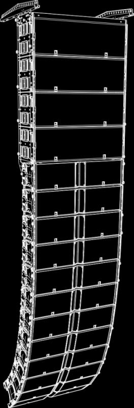
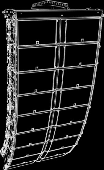
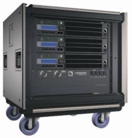
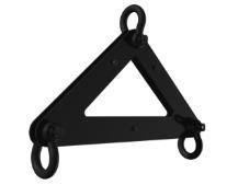
5 1 RIGGING SYSTEM The system approach developed by L-ACOUSTICS consists in providing packaged solutions for loudspeaker systems in order to guarantee the highest and most predictable level of performance at any step: modeling, installation, and operation. An L-ACOUSTICS loudspeaker system is the set of components available to form any loudspeaker system based on one of the full-range loudspeaker enclosures afforded by L-ACOUSTICS. It includes enclosures, rigging accessories, loudspeaker cables, amplified controllers and software applications. The main components involved in the rigging process of a K2 system are the following: 1.1 Loudspeaker enclosure K2 Full range enclosure, deployable in a variable curvature line source. K1-SB Dedicated subwoofer enclosure, deployable with K Rigging elements K2-CHARIOT K2-BUMP K2-BAR K1-DELTA K2-BUMPFLIGHT K2-LINK Transport dolly for four K2 enclosures. Rigging frame used to fly K2 line arrays. Designed to be compatible with K1 and K1-SB. Provided with two bow shackles WLL 3.25 t. Rigging bar designed to provide a wider range of site angles for the K2-BUMP. Provided with two bow shackles WLL 3.25 t. Rigging plate designed to be used optionally with the K2-BUMP, to adjust the azimuth angle of flown K2 / K1 / K1-SB arrays. Flight-case dedicated to the rigging elements of the K2 system. In order to be used as storage for the K2-BUMP it must be prepared using the foams provided with the product. Rigging interface between K2 and K1 or K1-SB. K2-RACKMOUNT Rigging interface for stacking one or two LA-RAK on top of a K2 array flown with a K2- BUMP. K2-BPCHAIN LA-SLING2T 1.3 Software application Adjustable sling used to prevent the chain bag of a climbing hoist being in front of a flown array top enclosure. Chain sling with two-leg bridles used to implement bridle hangs. SOUNDVISION Proprietary 3D acoustical and mechanical modeling software. 1.4 Accessories K2- CHARIOTCOV Protective cover for transportation and storage Other K2 SYSTEM components All the other components of the system are presented in the K2 user manual, document intended to describe the enclosure configurations and connection scheme. K2_RM_EN_0.5 w w w. l - a c o u s t i c s. c o m 5 / 52


6 K2 K1-SB LA-RAK K2-BUMP K2-BAR K2-LINK K1-DELTA K2-RACKMOUNT K2-CHARIOT LA-SLING2T K2-BPCHAIN SOUNDVISION Main components involved in the K2 rigging process K2_RM_EN_1.0 w w w. l - a c o u s t i c s. c o m 6 / 52
7 2 MECHANICAL SAFETY 2.1 Mechanical limits The K2 rigging system complies with 2006/42/EC: Machinery Directive. It has been designed following the guidelines of BGV-C /42/EC: Machinery Directive specifies a safety factor of 4:1 against the rupture. The limits specified in the tables below correspond to deployments with a safety factor of 4:1 or higher. Refer to SOUNDVISION for the safety factor of a specific deployment. The safe limit gives the maximum number of elements for which the safety factor is always compliant with the 2006/42/EC: Machinery Directive, regardless of the other deployment parameters (site angles, inter-enclosure angles, etc.). The maximum limit gives the maximum number of elements for which the safety factor can be compliant with the 2006/42/EC: Machinery Directive, when the other deployment parameters provide the best mechanical conditions. Ground-stacked Safe limit Maximum limit K2 on K1-SB with K2-BUMP 4 K2 6 K2 Flown K2-BUMP K2-BUMP + K2-BAR Safe limit 16 K2 14 K2 + 2 LA-RAK 12 K1-SB + 1 LA-RAK Maximum limit 24 K2 24 K2 + 2 LA-RAK 16 K1-SB + 2 LA-RAK K2-LINK under K1-BUMP 16 K2 24 K2 SOUNDVISION and mechanical safety To deploy more elements than the safe limits, or when mixing different type of loudspeaker enclosures within the same array, always model the system in SOUNDVISION before installation, and check the Mechanical Data section for any stress warning or stability warning. 2.2 Assessing mechanical safety In order to assess the actual safety of any array configuration before implementation, refer to the following warnings: Rated working load limit (WLL) is not enough The rated WLL is an indication of the element resistance to tensile stress. For complex mechanical systems such as loudspeaker arrays, WLLs cannot be used per se to determine the maximum number of enclosures within an array or to assess the safety of a specific array configuration. Mechanical modeling with SOUNDVISION The working load applied to each linking point, along with the corresponding safety factor, will depend on numerous variables linked to the composition of the array (type and number of enclosures, splay angles) and the implementation of the flying or stacking structure (number and location of flying points, site angle). This cannot be determined without the complex mechanical modeling and calculation offered by SOUNDVISION Assessing the safety with SOUNDVISION The overall safety factor of a specific mechanical configuration always corresponds to the lowest safety factor among all the linking points. Always model the system configuration with the SOUNDVISION software and check the Mechanical Data section to identify the weakest link and its corresponding working load. By default, a stress warning will appear when the mechanical safety goes beyond the recommended safety level. Safety of ground-stacked arrays in SOUNDVISION For ground-stacked arrays, a distinct stability warning is implemented in SOUNDVISION. It indicates a tipping hazard when the array is not secured to the ground, stage or platform. It is user responsibility to secure the array and to ignore this warning. Consideration must be given to unusual conditions SOUNDVISION calculations are based on usual environmental conditions. A higher safety factor is recommended with factors such as extreme high or low temperatures, strong wind, prolonged exposition to salt water, etc. Always consult a rigging specialist to adopt safety practices adapted to such a situation. K2_RM_EN_0.5 w w w. l - a c o u s t i c s. c o m 7 / 52

8 3 RIGGING SYSTEM DESCRIPTION K2 enclosures can be ground-stacked and flown independently (K2-BUMP) or in combination with K1 system elements (K1, K1-SB, or K1-BUMP). The K2-BUMP is designed to be directly compatible with K1 and K1-SB. The K2 enclosure rigging system requires the K2-LINK interface to be compatible with the K1 rigging system. 3.1 Elements for enclosure rigging On both sides, the K2 enclosure integrates two arms to connect to another element of the rigging system, such as an enclosure or to a flying frame. At the front, a rotating arm provides a fixed point around which the enclosure can freely rotate until its connection at the rear. At the rear, a sliding arm allows the inter-element angle setting and the inter-element rear connection. The angles between adjacent enclosures are secured by an automatic system that is activated in advance and locks itself during the stacking and lifting procedures. K2_RM_EN_1.0 w w w. l - a c o u s t i c s. c o m 8 / 52
9 3.2 Elements for storage and transportation The K2-CHARIOT is designed for the transportation and storage of blocks of four K2 enclosures. During transportation the blocks must have an inter-enclosure angle of 10 to avoid any separation of the enclosures. This angle must be set using the enclosure rear rigging arm pin. The automatic locking system must remain unloaded. The K2-CHARIOT rear rigging arm must be at its -15 site angle position. TIPPING HAZARD If the enclosures are not pinned at 10, they can separate at the back, causing the stack to tip over. K2_RM_EN_0.5 w w w. l - a c o u s t i c s. c o m 9 / 52


10 3.3 Elements for flying The K2-BUMP is designed for flying line arrays of K2, K1 or K1-SB enclosures. 4 holes are available on the central bar of the K2-BUMP. Refer to your SOUNDVISION model to know which holes to use. With K1-SB and a single motor the hole n o 2 provides a 0 site angle. By adding a K2-BAR to the K2-BUMP, the site angle range can be increased. 21 holes are available on the K2-BAR which can be attached to the K2-BUMP as a rear or a front extension and in position A or B, thus offering a total of 84 discrete positions for pick-up points. The rear extension is suited to downwards and front extension to upwards site angles. K2_RM_EN_1.0 w w w. l - a c o u s t i c s. c o m 10 / 52


11 Standard: One K2-BAR attached in the center of K2-BUMP Alternative: Two K2-BAR attached on the sides The K2 system can be flown under a K1 system element, K1, K1-SB or K1-BUMP. The K2-LINK is designed to make the rigging systems compatible. It provides three holes and therefore three angles between the top K2 enclosure and the bottom K1 element: 0.25, 2.5 and 5. K2_RM_EN_0.5 w w w. l - a c o u s t i c s. c o m 11 / 52


12 3.4 Elements for LA-RAK rigging The K2-RACKMOUNT is designed to stack one or two LA-RAK on top of a flown array. It is composed of four rails and a stabilizer. The rails are screwed on the K2-BUMP. Their number and position depend on the number of racks. The K2-RACKMOUNT must be used along with either one or two K2-BAR. 1 LA-RAK : 2 rails : 2 K2-BAR 2 LA-RAK : 4 rails : 1 K2-BAR K2_RM_EN_1.0 w w w. l - a c o u s t i c s. c o m 12 / 52


13 When two racks are mounted side by side, the stabilizer is used to prevent the assembly from tipping or toppling over. The stabilizer traps one of the chains used to lift the assembly. 0 site angle 30 positive site angle Refer to APPENDIX A: PICKUP POINTS GUIDELINES for more information. K2_RM_EN_0.5 w w w. l - a c o u s t i c s. c o m 13 / 52

14 4 SYSTEM SETUP 4.1 Ground-stacking Final check After the setup, always verify no yellow labels are visible on the front and on both sides of the array. K2 enclosures on K1-SB Stack as many K1-SB enclosures as necessary. Refer to the K1 rigging manual to set up the K1-SB part of the array. Position and attach a K2-BUMP on the K1-SB stack Refer to PROCEDURE H. Position and attach an upside down K2 on the K2-BUMP and add as many K2 enclosures on top of the first one. Refer to PROCEDURE C. K2_RM_EN_1.0 w w w. l - a c o u s t i c s. c o m 14 / 52


15 4.2 Flying Final check After the setup, always verify no yellow labels are visible on the front and on both sides of the array. At least one motor for each K2-BAR When using two K2-BAR, do not implement a bridle between the bars. Before setup, choose a flying option Refer to SOUNDVISION modeling and to 3.3 Elements for flying (p. 2). K2 enclosures under K2-BUMP Prepare all the blocks of 4 K2 necessary to build the array. If a block is not already built, refer to PROCEDURE A. Preset the inter-enclosures angles. Refer to PROCEDURE B. Place an open a K2-BUMPFLIGHT under the motor. If necessary, attach one or two K2-BAR to the K2-BUMP. Refer to PROCEDURE D. If necessary, stack one or two LA-RAK on the K2-BUMP. Refer to PROCEDURE I. Refer to APPENDIX A: when stacking only one LA-RAK. Attach the shackles. Refer to SOUNDVISION for the number and position of the shackles. Lift the assembly so you can position a block of four K2 under it. Attach the block of four K2 to the K2-BUMP Refer to PROCEDURE E. Verify that the rear rigging arms are secured by pins and that no yellow label is visible on the front. Lift the assembly so you can position a block of four K2 under it. Verify that no yellow label is visible on both sides of the array. Attach the block of four K2 enclosures to the bottom of the array. Refer to PROCEDURE F. Verify that the rigging arms at the back are secured by pins and that no yellow label is visible on the front. Repeat the last two steps until the array is complete. Raise the array to its final trim height. Adjust site and azimuth angles. K2_RM_EN_0.5 w w w. l - a c o u s t i c s. c o m 15 / 52
.")

16 Final check After the setup, always verify no yellow labels are visible on the front and on both sides of the array. When using two K2-BAR, do not implement a bridle between the bars. Always use at least two motors. Refer to APPENDIX A: PICKUP POINTS GUIDELINES. Before setup, choose a flying option Refer to SOUNDVISION modeling and to 3.3 Elements for flying (p. 2). K2 enclosures under K1-SB K1-SB array setup Refer to your SOUNDVISION model to define which flying frame to use. If you are using the K1-BUMP: Refer to the K1 rigging manual to set up the K1-SB part of the array. Or if you are using the K2-BUMP: Place an open a K2-BUMPFLIGHT under the motor. If necessary, attach one or two K2-BAR to the K2-BUMP. Refer to PROCEDURE D. If necessary, stack one or two LA-RAK on the K2-BUMP. Refer to PROCEDURE I. Refer to APPENDIX A: when stacking only one LA-RAK. Attach the shackles. Refer to SOUNDVISION for the number and position of the shackles. Lift the assembly so you can position a block of K1-SB under it. Attach the K1-SB block to the K2-BUMP. Refer to PROCEDURE H. Repeat the last two steps until the K1-SB array is complete. K2 array setup Prepare all the blocks of 4 K2 necessary to build the array If a block is not built already, refer to PROCEDURE A. Preset the inter-enclosures angles. Refer to PROCEDURE B. K1-SB and K2 arrays connection Lift the K1-SB array so you can position a block of four K2 under it. Using two K2-LINK interfaces, attach the block of K2 under the K1-SB array. Refer to PROCEDURE G. Verify that the rear rigging arms are secured by pins and that no yellow label is visible on the front. Lift the array so you can position a block of four K2 under it. Verify that no yellow label is visible on both sides of the array. Attach the block of four K2 to the bottom enclosure of the array. Refer to PROCEDURE F. Verify that the rear rigging arms are secured by pins and that no yellow label is visible on the front. Repeat the last two steps until the array is complete. Raise the array to its final trim height. Adjust site and azimuth angles. K2_RM_EN_1.0 w w w. l - a c o u s t i c s. c o m 16 / 52


17 5 SUBSET PROCEDURES PROCEDURE A. Preparing a block of 4 K2 1. Attach a K2 enclosure on K2-CHARIOT. Fully rotate the rear rigging arms of the K2-CHARIOT. Position the K2 enclosure on the K2-CHARIOT dolly Secure the enclosure at the front using the LINK hole. Lift the rear of the enclosure and rotate the dolly rear rigging arm in its upward position. Secure the enclosure using the LINK hole. K2_RM_EN_0.5 w w w. l - a c o u s t i c s. c o m 17 / 52


18 2. Attach the other K2 enclosures on top of each other until the block of four is complete. While holding the handle, rotate the front rigging arm and secure it with both LINK pins. Position a K2 enclosure on the first one. Slide the rear rigging arm and secure it with both pins, in the LINK and 10 holes. Keep holding the enclosure in position with the handles until the front rigging arm is secured. 3. Make sure the automatic locking system button is unloaded. If the button has been pressed, pull to disengage the latch K2_RM_EN_1.0 w w w. l - a c o u s t i c s. c o m 18 / 52

19 PROCEDURE B. Preset the inter-enclosure angles On both sides: Remove the pin from its current angle hole Position the pin at the chosen angle hole and slide the rigging arm until the pin goes in. Press the lock button K2_RM_EN_0.5 w w w. l - a c o u s t i c s. c o m 19 / 52


20 PROCEDURE C. Stacking K2 on K2-BUMP 1. Prepare the K2 block top enclosure and turn it upside down on the K2-BUMP. Take out and lock the rear and front rigging arms. Define the K2 line site angle with the rear rigging arm. Select a value between 0.25 and 7.5 and substract 3 to obtain the final site angle. Remove the lower rear and front pins. K2_RM_EN_1.0 w w w. l - a c o u s t i c s. c o m 20 / 52


21 The rigging arms should rest of the K2-BUMP spacers. 2. Secure the K2 enclosure on the K2-BUMP. Secure the front and rear rigging arm to the K2-BUMP. Slide the front rigging arm up and down to align the holes. Secure the front rigging arm to the K2 enclosure. Raise the enclosure to align the holes. Push the locking system button to unblock the lock. 3. Prepare the K2 block top enclosure Adjust the inter-enclosure angle with the rear rigging arm. Remove the lower front and rear pins. K2_RM_EN_0.5 w w w. l - a c o u s t i c s. c o m 21 / 52


22 4. Turn the K2 enclosure upside down, lower it and secure it on the other K2. Secure the front and rear rigging arm to the lower K2 enclosure. Secure the front and rear rigging arm to the K2-BUMP. Slide the front rigging arm up and down to align the holes. Secure the front rigging arm to the top enclosure. Raise the top enclosure to align the holes. Push the locking system button to unblock the lock. 5. Repeat steps 3 to 5 until the line is complete. K2_RM_EN_1.0 w w w. l - a c o u s t i c s. c o m 22 / 52


23 PROCEDURE D. Attaching K2-BAR on K2-BUMP 1. Refer to your SOUNDVISION model to identify the extension and position of the bar. K2_RM_EN_0.5 w w w. l - a c o u s t i c s. c o m 23 / 52


24 2. Remove the pins and lift the K2-BAR using the motor. 3. Turn the K2-BUMP-FLIGHT 90, lower the K2-BAR and pin it according to the chosen flying option (position A or B, in front or rear extension) K2_RM_EN_1.0 w w w. l - a c o u s t i c s. c o m 24 / 52


25 PROCEDURE E. Attaching a block of four K2 under K2-BUMP 1. Lower the K2-BUMP to allow for front connection. 2. Attach the front rigging arm on both sides. Preset inter-enclosure angles Preset the K2 inter-enclosure angles before performing this procedure. Refer to PROCEDURE B. Rotate the arm and secure it with the K2-BUMP pin. Lower the K2-BUMP and secure the connection with the K2 pin. If you cannot insert the pin, move the frame back and fortt. 3. Lower the rear of the K2-BUMP. 4. Attach the rear rigging arm to the frame. Slide the arm to its 5 position. Secure the arm with the frame pin. Preset the angle at 5 with the enclosure pin. Do not lower until contact. Leave a gap allowing to slide the K2 arm to its 5 position. K2_RM_EN_0.5 w w w. l - a c o u s t i c s. c o m 25 / 52


26 5. Raise the array to lock the enclosures 6. Remove the K2-CHARIOT Hold the dolly with one hand. Remove the back pin on both sides. Hold the dolly with one hand. Remove the front pin on both sides. K2_RM_EN_1.0 w w w. l - a c o u s t i c s. c o m 26 / 52


27 PROCEDURE F. Attaching a block of four K2 under K2 7. Attach the front rigging arm on both sides. Preset inter-enclosure angles Rotate the arm to align its hole with the K2 rigging hole. Preset the K2 inter-enclosure angles before performing this procedure. Refer to PROCEDURE B. Pin the arm in the LINK hole of the flown array. Lower the flown array and secure the assembly with the LINK pin. If you cannot insert the pin, move the flown array back and forth with enclosure handle. K2_RM_EN_0.5 w w w. l - a c o u s t i c s. c o m 27 / 52


28 8. Lock the inter-enclosure angles of the block Raise the array. The lower K2 enclosures swing and the latches automatically lock. K2_RM_EN_1.0 w w w. l - a c o u s t i c s. c o m 28 / 52


29 9. Attach the lower K2 enclosures rear rigging arm to the back of the array. Turn the wheels inside the dolly. Pull back the bottom enclosures while lowering the array until the array and the top enclosure of the block are in contact. Slide the arm upward and secure it with the pin using the LINK hole. Position the pin at the entrance of the chosen angle hole and slide the rigging arm until the pin goes in. Press the lock button K2_RM_EN_0.5 w w w. l - a c o u s t i c s. c o m 29 / 52
30 10. Raise the array to lock the inter-enclosure angle. The latches automatically lock. 11. Remove the K2-CHARIOT Hold the dolly with one hand. Remove the back pin on both sides. Hold the dolly with one hand. Remove the front pin on both sides. K2_RM_EN_1.0 w w w. l - a c o u s t i c s. c o m 30 / 52


31 PROCEDURE G. Attaching a block of four K2 under a K1 system element Preset inter-enclosure angles Preset the K2 inter-enclosure angles before performing this procedure. Refer to PROCEDURE B. 1. Attach the front rigging arm on both sides. Rotate the arm to align its hole with the K1/K1-SB rigging hole. Pin the arm on the flown array. Lower the flown array and secure the assembly with the LINK pin. If you cannot insert the pin, move the flown array back and forth with enclosure handle. K2_RM_EN_0.5 w w w. l - a c o u s t i c s. c o m 31 / 52


32 2. Lock the inter-enclosure angles. Raise the array. K2_RM_EN_1.0 w w w. l - a c o u s t i c s. c o m 32 / 52


33 3. Attach the K2-LINK interfaces to the K1/K1-SB. Turn the wheels inside the dolly. Pull back the bottom enclosures while lowering the array until only the front wheel touches the ground. On both sides, attach a K2-LINK at the back of the K1-SB enclosure. Do not pin K2-LINK on K2. K2_RM_EN_0.5 w w w. l - a c o u s t i c s. c o m 33 / 52


34 4. Attach the K2-LINK to the K2 enclosure. Lower the array Push the K2-LINK to guide it into the K2 rigging. Secure the K2-LINK on the K2 rigging middle hole. 5. K2_RM_EN_1.0 w w w. l - a c o u s t i c s. c o m 34 / 52

35 5. Remove the K2-CHARIOT Raise the array Hold the dolly with one hand. Remove the back pin on both sides. Hold the dolly with one hand. Remove the front pin on both sides. K2_RM_EN_0.5 w w w. l - a c o u s t i c s. c o m 35 / 52


36 PROCEDURE H. Attaching K1 or K1-SB under K2-BUMP 1. Slide out K1-SB front rigging arm and pin it at 0 on both sides. 2. Attach the K2-BUMP to the K1 elements block. Remove the K2-BUMP rear and front pins on both sides. Lower the K2-BUMP so it rest on the topmost enclosure. Rotate the rear rigging arm and pin it on the frame. Pin the front rigging arm on the frame. K2_RM_EN_1.0 w w w. l - a c o u s t i c s. c o m 36 / 52


37 PROCEDURE I. Stacking LA-RAK on K2-BUMP Tools Electric screwdriver with torque selector. 6 mm hex bit. Wrench with 13 mm hex socket. 1. Remove the nuts and bolts from the K2-RACKMOUNT rails. 2. Position and secure as many rails as necessary on the K2-BUMP. 1 LA-RAK 2 LA-RAK 3. Secure the rails on the K2-BUMP. Use the wrench with a 13 mm hex socket and the electric screwdriver. Set the torque to 5 N.m. Before securing the side rails, make sure the frame pins are on the outside. K2_RM_EN_0.5 w w w. l - a c o u s t i c s. c o m 37 / 52
38 4. Install as many K2-BAR as necessary. When installing a single K2-BAR at the center of the frame, make sure the pins are inserted between the central bar of the frame and the closest rail. K2_RM_EN_1.0 w w w. l - a c o u s t i c s. c o m 38 / 52


, from the front for a positive angle (front extension).")
39 5. Attach the LA-RAK on the K2-BUMP. Remove the LA-RAK coupling bars Turn the bars to release the spring-loaded safety and slide them out. Position the LA-RAK on the rails. Secure the LA-RAK with the coupling bars. Insert the spring-loaded safety in the LA-RAK rails, give a quarter turn and slide the bar until the safety locks into place. Insert the coupling bars: from the back for a negative angle (rear extension), from the front for a positive angle (front extension). Always insert so the metallic safety is pointed upward (depending on the tilt angle). K2_RM_EN_0.5 w w w. l - a c o u s t i c s. c o m 39 / 52


40 6. If you are stacking 2 LA-RAK side-by-side on K2-BUMP, insert the stabilizer between the two racks. Release the locking system by raising and turning the handle. Insert the stabilizer on the side opposite to the K2-BAR: from the front in rear extension from the rear in front extension. Secure the stabilizer by locking the handle. K2_RM_EN_1.0 w w w. l - a c o u s t i c s. c o m 40 / 52


41 APPENDIX A: PICKUP POINTS GUIDELINES A K2 system can be lifted using one or two motors: One or two motors with K2-BUMP alone. Two motors with K2-BUMP and one K2-BAR. Two with K2-BUMP and two K2-BAR. K2-BUMP with LA-RAK OK NOT OK OK With a single LA-RAK on top of a K2-BUMP, always implement a bridle suspension using two LA-SLING2T. K2_RM_EN_0.5 w w w. l - a c o u s t i c s. c o m 41 / 52
 Never use slings shorter that 1 m (39.")

42 Use two LA-SLING2T to implement bridle hangs. Specifications Lifting chain (DIN EN 818-4) 2-leg, 8 mm Steels grade 8 Nominal length incl. hooks 1 m / 39.4 in Maximum sling angle β max 60 Load rating 2.8 t for β : t for β : ) Never use slings shorter that 1 m (39.4 in). One leg of the LA-SLING2T must always be connected to the K2-BAR hole n o 1 (i.e., the closest to the array). The other leg can be connected to holes n o 11 to n o 21. Refer to your SOUNDVISION simulation to choose the hole. K2_RM_EN_1.0 w w w. l - a c o u s t i c s. c o m 42 / 52


43 K2-BUMP with no LA-RAK OK NOT OK With two K2-BAR on a K2-BUMP, do not implement a bridled suspension between the two bars. Do not implement a bridled suspension on a single K2-BAR. K2_RM_EN_0.5 w w w. l - a c o u s t i c s. c o m 43 / 52


44 K1-DELTA for azimuth control To control the azimuth of a flown K2 line, attach the K1-DELTA to the rear pickup point. The recommended space between the two lifting point is 1 m / 33 ft. By adjusting the height of both pickup points you can adjust the azimuth angle from -10 to +10. K2-BPCHAIN with a climbing hoist With a climbing hoist you must use a K2-BPCHAIN adjustable sling to prevent the chain bag from hanging in front of the top enclosures of the array. Electric chain hoists Climbing hoists K2_RM_EN_1.0 w w w. l - a c o u s t i c s. c o m 44 / 52
 1. Remove the four M4 Torx screws (T20) from the plate. 2. Put thread-locker in the four threaded inserts. 3. Position the LAP-TEQ so it points toward the front of the K2-BUMP.")
45 APPENDIX B: INSTALLING A LASER INCLINOMETER The K2 rigging system is compatible with the following laser inclinometers: TEQSAS LAP-TEQ (part of the L-ACOUSTICS TECH TOOLCASE) SSE ProSight TEQSAS LAP-TEQ XLR 3 cable T20 Torx key Medium-strength thread-locker (blue) 1. Remove the four M4 Torx screws (T20) from the plate. 2. Put thread-locker in the four threaded inserts. 3. Position the LAP-TEQ so it points toward the front of the K2-BUMP. 4. Secure the LAP-TEQ with the four screws. 5. Connect the XLR 3 cable to the sensor. 6. Follow the manufacturer instructions to calibrate the inclinometer. K2_RM_EN_0.5 w w w. l - a c o u s t i c s. c o m 45 / 52
![APPENDIX C: SPECIFICATIONS K2 Description Usable bandwidth (-10 db) Maximum SPL 1 Coverage angle (-6 db) Transducers 3-way active enclosure, quad-amplified by LA4X or LA8 35 Hz - 20 khz ([K2_70]](/docs-images/82/86608005/images/46-1.jpg "preset) 145 db ([K2_70] preset) Horizontal : 110 / 70 symmetric 90 asymmetric (35 / 55 or 55 / 35 ) Vertical : dependent upon number of elements and array curvature LF: 2 12\", weather-resistant,")
46 APPENDIX C: SPECIFICATIONS K2 Description Usable bandwidth (-10 db) Maximum SPL 1 Coverage angle (-6 db) Transducers 3-way active enclosure, quad-amplified by LA4X or LA8 35 Hz - 20 khz ([K2_70] preset) 145 db ([K2_70] preset) Horizontal : 110 / 70 symmetric 90 asymmetric (35 / 55 or 55 / 35 ) Vertical : dependent upon number of elements and array curvature LF: 2 12", weather-resistant, bass-reflex MF: 4 6.5", weather-resistant, bass-reflex HF: 2 3", diaphragm compression driver, DOSC waveguide Nominal impedance LF = 2 8 Ω, MF = 8 Ω, HF = 16 Ω LF: 450 W RMS power handling MF: 320 W HF: 160 W Connectors IN: 1 8-point PA-COM LINK: 1 8-point PA-COM Rigging components Captive 4-point rigging system Inter-enclosure angles: 0.25, 1, 2, 3, 4, 5, 7.5 or 10 Dimensions Physical data Weight (net): Cabinet: Finish: Front: Protection Rating: Rigging component: 56 kg / lb first grade Baltic birch plywood Dark Grey brown (proprietary color) Pure white RAL 9010 Steel grill with polyester anti-corrosion coating Airnet acoustically neutral fabric IP45 High grade steel with polyester anti-corrosion coating 1 Peak level at 1 m under half-space conditions using 10 db crest factor pink noise with specified preset. K2_RM_EN_1.0 w w w. l - a c o u s t i c s. c o m 46 / 52
![K1-SB Description Low frequency limit ( 10 db) Maximum SPL 1 RMS power handling Transducer Nominal impedance Subwoofer enclosure, amplified by LA8 34 Hz ([K1SB_X] preset) 143 db ([K1SB_X] preset)](/docs-images/82/86608005/images/47-1.jpg "1200 W 2 15\", weather-resistant, bass-reflex 4\" coil, magnesium die-cast basket, vented magnet design 4 Ω Connectors IN: 1 4-point SpeakON Rigging components 2 Captive 4-point rigging system")
47 K1-SB Description Low frequency limit ( 10 db) Maximum SPL 1 RMS power handling Transducer Nominal impedance Subwoofer enclosure, amplified by LA8 34 Hz ([K1SB_X] preset) 143 db ([K1SB_X] preset) 1200 W 2 15", weather-resistant, bass-reflex 4" coil, magnesium die-cast basket, vented magnet design 4 Ω Connectors IN: 1 4-point SpeakON Rigging components 2 Captive 4-point rigging system Inter-enclosure angles: 0, 0.5, 1, 1.5, 2, 2.5, 3, 4 or 5 Handles integrated in the cabinet Dimensions Physical data Weight (net): Cabinet: Finish: Front: Protection Rating: Rigging components: 83 kg / 183 lb Baltic birch plywood Dark Grey brown Pantone 426C Pure white RAL 9010 Steel grill with anti-corrosion coating Airnet acoustically neutral fabric IP45 High strength steel with anti-corrosion coating 1 Peak level at 1 m under half-space conditions using 10 db crest factor pink noise with specified preset. K2_RM_EN_0.5 w w w. l - a c o u s t i c s. c o m 47 / 52


48 K2-BUMP Description Rigging frame for K2 enclosure Dimensions Weight 42.3 kg / 93.3 lb Material High-grade steel with anti-corrosion coating. K2-BUMP-FLIGHT Description Flight-case for the K2 system rigging elements. Dimension s Weight 105 kg / 231 lb K2_RM_EN_1.0 w w w. l - a c o u s t i c s. c o m 48 / 52


49 K2-BAR Description Rigging bar for K2-BUMP. Dimensions Weight 17 kg / 37.5 lb Material High-grade steel with anti-corrosion coating K2-LINK Description Rigging interface for K2 and K1, K1-SB or K1-BUMP. Dimensions Weight 1.8 kg / 4 lb Material High-grade steel with anti-corrosion coating K2_RM_EN_0.5 w w w. l - a c o u s t i c s. c o m 49 / 52


50 K2-RACKMOUNT Description Rigging interface for stacking one or two LA-RAK on top of a K2 array flown with a K2-BUMP. Dimensions Weight 3.3 kg / 7.3 lb Material Steel with anti-corrosion coating. Description Stabilizer for two LA-RAK side by side on top of a K2 array flown with a K2-BUMP. Dimensions Weight 2.2 kg / 4. lb Material Steel with anti-corrosion coating. K2_RM_EN_1.0 w w w. l - a c o u s t i c s. c o m 50 / 52


51 K1-DELTA Description Rigging element for the K1 system Dimensions Weight 9,5 kg / 21 lbs. Material High-grade steel with anti-corrosion coating K2-CHARIOT Description Transport dolly for the K2 enclosure. Dimensions Weight 50 kg / lb Material Steel with anti-corrosion coating. K2_RM_EN_0.5 w w w. l - a c o u s t i c s. c o m 51 / 52
52 Document reference: K2_RM_EN_1.0 Distribution date: December 6, L-ACOUSTICS. All rights reserved. No part of this publication may be reproduced or transmitted in any form or by any means without the express written consent of the publisher. K2_RM_EN_1.0 w w w. l - a c o u s t i c s. c o m 52 / 52
KIVA SYSTEM KIVA SB15m
 RIGGING MANUAL www.l-acoustics.com rigging manual SAFETY INSTRUCTIONS 1. Read this manual 2. Follow all SAFETY INSTRUCTIONS as well as DANGER and OBLIGATION warnings 3. Never incorporate equipment or accessories
LA-RAK II. rigging manual (EN)
") LA-RAK II rigging manual (EN) Document reference: LA-RAK II rigging manual (EN) version 1.0 Distribution date: February 28, 2017 2017 L-Acoustics. All rights reserved. No part of this publication may be
LA-RAK II rigging manual (EN) Document reference: LA-RAK II rigging manual (EN) version 1.0 Distribution date: February 28, 2017 2017 L-Acoustics. All rights reserved. No part of this publication may be
KARA modular wst. modular wst system RIGGING PROCEDURES VERSION
 KARA modular wst RIGGING PROCEDURES VERSION 1.1 modular wst system www.l-acoustics.com w w w. l - a c o u s ti c s. co m 1 SAFETY S All information hereafter detailed applies for the L-ACOUSTICS M-BUMP
KARA modular wst MINIBU. modular wst system RIGGING PROCEDURES USING KARA VERSION
 KARA modular wst modular wst system KARA-MINI MINIBU RIGGING PROCEDURES USING KARA VERSION 1.0 www.l-acoustics.com w w w. l - a c o u s ti c s. co m 1 SAFETY S All information hereafter detailed applies
Figure 35: Assembling a KARA-MINIBU/KARAMINIBUEX stacking platform
 Laser plate a. Identification plate KARA-MINIBU b. Stud inserted into slit c. Bolts (x3) KARA-MINIBUEX (x2) Figure 35: Assembling a KARA-MINIBU/KARAMINIBUEX stacking platform 2. If KARA-ANGARMEX are intended
PRODUCT INFORMATION BOOKLET Document Reference: SPK_T_PIB_EN_1.3 Distribution Date: October 30th, SpekTrix-t [ ]
![PRODUCT INFORMATION BOOKLET Document Reference: SPK_T_PIB_EN_1.3 Distribution Date: October 30th, SpekTrix-t [ ]](/thumbs/95/125057420.jpg "PRODUCT INFORMATION BOOKLET Document Reference: SPK_T_PIB_EN_1.3 Distribution Date: October 30th, SpekTrix-t [ ]") SpekTrix-t [972-0008] PRODUCT INFORMATION BOOKLET Document Reference: SPK_T_PIB_EN_1.3 Distribution Date: October 30th, 2014 Adamson Systems Engineering E15 Product Information Booklet Page 1 2014 Adamson
SpekTrix-t [972-0008] PRODUCT INFORMATION BOOKLET Document Reference: SPK_T_PIB_EN_1.3 Distribution Date: October 30th, 2014 Adamson Systems Engineering E15 Product Information Booklet Page 1 2014 Adamson
Elevation Series Subwoofer
 Elevation Series Subwoofer Features: Tapped Horn Subwoofer Design (patent pending) Extremely High SPL for Cabinet Size Low Distortion Down to 35Hz Solid Marine Grade Plywood Cabinet Construction Available
PRODUCT INFORMATION BOOKLET Document Reference: SPK_SUB_PIB_EN_1.3 Distribution Date: October 30th, SpekTrix Sub [ ]
![PRODUCT INFORMATION BOOKLET Document Reference: SPK_SUB_PIB_EN_1.3 Distribution Date: October 30th, SpekTrix Sub [ ]](/thumbs/96/127560627.jpg "PRODUCT INFORMATION BOOKLET Document Reference: SPK_SUB_PIB_EN_1.3 Distribution Date: October 30th, SpekTrix Sub [ ]") SpekTrix Sub [992-0005] PRODUCT INFORMATION BOOKLET Document Reference: SPK_SUB_PIB_EN_1.3 Distribution Date: October 30th, 2014 Adamson Systems Engineering E15 Product Information Booklet Page 1 2014
SpekTrix Sub [992-0005] PRODUCT INFORMATION BOOKLET Document Reference: SPK_SUB_PIB_EN_1.3 Distribution Date: October 30th, 2014 Adamson Systems Engineering E15 Product Information Booklet Page 1 2014
datasheet TCS-122 TCS-122DP
 DP The is a two-way loudspeaker enclosure available in either switchable active/passive or optional digitally self-powered formats, and designed for use in a wide range of fixed installations. It consists
Contents: 1.1 Metrix Series Introduction p What is in the Metrix? p Rigging Options & Adapters p Accessories p.
 Contents: 1.1 Metrix Series Introduction p.4 1.2 What is in the Metrix? p.5 1.3 Rigging Options & Adapters p. 6-9 1.4 Accessories p. 10 1.5 Spec Sheets p.11-16 1.6 Metrix standard amp configuration p.17-19
JBL VTX-V20-DF SUSPENSION MANUAL
 JBL VTX-V20-DF 1 Contents JBL VTX-V20-DF... 1 IMPORTANT SAFETY WARNING... 3 APPLICATION OF V20-DF... 7 ATTACHMENT OF V20-DF TO V25-II / V25-II-CS... 8 JBL VTX SERIES SUSPENSION PRECAUTIONS AND SAFETY INFORMATION
C300z PRECISION PASSIVE LOUDSPEAKER. FEATURES: 2-way portable Precision Passive loudspeaker system APPLICATIONS
 C300z Featuring legendary Mackie sound quality and durability, the lightweight C Series 2-way Precision Passive loudspeakers deliver optimum performance in portable PA, stage monitor and permanent installation
*TD * WideLine Series Loudspeaker System User Manual. WL218-sw subwoofer line array loudspeaker AF218-sw subwoofer array frame
 1675 MacArthur Blvd., Costa Mesa, CA, 92626 USA Main Number (714) 754-6175 Sales & Marketing (714) 957-7100 or toll free (USA only) (800) 854-4079 Customer Service(714) 957-7150 or toll free (USA only)
X-LINE ADVANCE Systems
 X-LINE ADVANCE Systems X1-212/90, X12-128, X2-212/90, X12TC-GRID, X12TE-GRID, X12PU-BGK, X12T-DOLLY, and X12-128-DOLLY en Installation Manual en 3 Table of contents 1 Safety 5 1.1 Important Safety Instructions
ASSEMBLY GUIDE CONCERT SERIES 700-HP RIGGING GRID AND ACCESSORIES
 ASSEMBLY GUIDE CONCERT SERIES 700-HP RIGGING GRID AND ACCESSORIES CONTENTS This Assembly Guide provides instructions on how to safely assemble and use the MRK-700 rigging kit, MTG-700 top grid and MCF-700
CROSS FIELD ARRAY-2 (CFA-2) Long Throw/High Intelligibility All-Weather Loudspeaker System V100/2015
 Long Throw/High Intelligibility All-Weather Loudspeaker System V100/2015") CROSS FIELD ARRAY-2 (CFA-2) Long Throw/High Intelligibility All-Weather Loudspeaker System V100/2015 The One Systems Cross Field Array-2 (CFA-2) was designed to provide very high intelligibility and acoustic
CROSS FIELD ARRAY-2 (CFA-2) Long Throw/High Intelligibility All-Weather Loudspeaker System V100/2015 The One Systems Cross Field Array-2 (CFA-2) was designed to provide very high intelligibility and acoustic
IB-TPK Tight Pack Kit ibox Series Suspension Brackets
 IB-TPK Tight Pack Kit ibox Series Suspension Brackets Tight pack suspension brackets for Community s ibox installation series loudspeakers Community s Tight Pack Kit is designed to safely and conveniently
*TD * ILA Series Loudspeaker System User Manual
 1675 MacArthur Blvd., Costa Mesa, CA, 92626 USA Main Number (714) 754-6175 Sales & Marketing (714) 957-7100 or toll free (USA only) (800) 854-4079 Customer Service(714) 957-7150 or toll free (USA only)
USER MANUAL PXH64. PX System Mid/High Element
 USER MANUAL PXH64 PX System Mid/High Element CONTENT INTRODUCTION - 2 - SAFETY FIRST - 2 - UNPACKING - 3 - PX SYSTEM OVERVIEW - 4 - PXH64 OVERVIEW - 5 - CABLE SELECTING - 5 - CONNECTION AND ELECTRIC DIAGRAM
Product specifications
 Product specifications THE MOST POWERFUL 3-WAY SUB-COMPACT LINE ARRAY FOR USE IN 3- or 4-WAY SYSTEMS PRECISE ANGULAR CONTROL HIGH SPL MORE VERSATILE & SCALABLE The Adamson Y10 is the highest fidelity sub-compact
DD6 ULTRA-COMPACT DIFFERENTIAL DISPERSION SYSTEM
 DD6 ULTRA-COMPACT DIFFERENTIAL DISPERSION SYSTEM TOURING AND THEATRE DD6 ULTRA-COMPACT DIFFERENTIAL DISPERSION SYSTEM The DD6 adopts advanced Differential Dispersion technology to deliver more consistent
The Neumann KH 420. A digital input module (DIM 1) with a delay feature for lipsync and time-of-flight adjustment can be added.
 with a delay feature for lipsync and time-of-flight adjustment can be added.") three-way monitor kh 420 english kh 420 The Neumann KH 420 The KH 420 represents the result of using the latest techniques in acoustical, electronic 1 3 4 2 and mechanical design to bring a new benchmark
three-way monitor kh 420 english kh 420 The Neumann KH 420 The KH 420 represents the result of using the latest techniques in acoustical, electronic 1 3 4 2 and mechanical design to bring a new benchmark
6. BI-AMPLIFIER AND SINGLE-AMPLIFIER OPERATIONS 6.1. Bi-Amplifier Operation Single-Amplifier Operation... 9
 LINE ARRAY SPEAKERS OPERATING INSTRUCTIONS SR-C8L SR-C8S SR-C15B RIGGING FRAME RIGGING SUPPORT BRACKET TILT JOINT BRACKET CLUSTER BRACKET SR-RF8 SR-SB8 SR-TP8 SR-CL8 Note that casters must be prepared
PM10 10-inch 2-Way Main/Monitor
 PM10 10inch 2Way Main/Monitor Features Compact light weight Design HeavyDuty 10 Woofer 1inch exit (1.5 VC) HF driver Durable Water Resistant Enclosure Application The PM10 is designed to stand alone as
HDL 26-A ACTIVE TWO WAY LINE ARRAY MODULE
 HDL 26-A ACTIVE TWO WAY LINE ARRAY MODULE DESCRIPTION The RCF HDL26-A is an ultra-compact biamped two-way active touring system for small and medium-sized events, both indoors and outdoors. Due to the
X-ARRAY CONCERT SYSTEMS. Flying Manual and Structural Ratings
 X-ARRAY CONCERT SYSTEMS Flying Manual and Structural Ratings RIGGING-SAFETY WARNING This document details general rigging practices appropriate to the sound industry, as they would apply to the rigging
15 2 Way Powere 8 x 55 Speaker System. single 18 Powere su woofer
 In physics, plasma is the fourth state of matter: Solid moves to liquid moves to gas moves to PLASMA. The tremendous power and energy of this material state inspired our Electro- Voice design team to name
PDS V Pendant Ball Loudspeaker
 PDS 660 100V Pendant Ball Loudspeaker User Manual Order code: CRSP51 Safety advice WARNING FOR YOUR OWN SAFETY, PLEASE READ THIS USER MANUAL CAREFULLY BEFORE YOUR INITIAL START-UP! Immediately upon receiving
Contents. The d&b System reality The J-Series The J8 loudspeaker The J12 loudspeaker The J subwoofer...12
 J J-Series Contents The d&b System reality... 4 The J-Series... 8 The loudspeaker...10 The loudspeaker...11 The J subwoofer...12 The J-INFRA subwoofer...13 The J-Series rigging system...14 The J-Series
Transducer complement: Heavy duty 12" woofer with a 2 3/8" voice coil, RX14 1.4" titanium diaphragm dynamic compression drive
 SPECIFICATIONS PR 12 Frequency range (-10 db, half space): 54 Hz to 21 khz Sensitivity (1 watt/1 meter): 97 db Power rating (program): 400 watts Power capacity (peak): 800 watts Transducer complement:
V SERIES BRACKETS AND ACCESSORIES GUIDE. V SERIES Brackets and Accessories Guide Page 1
 V SERIES BRACKETS AND ACCESSORIES GUIDE V SERIES Brackets and Accessories Guide Page 1 NOTICE The brackets and accessories described in this guide are for illustrative purposes only. Please refer to the
EXCELLENT SPEECH AND MUSIC REPRODUCTION NO COMPROMISE BETWEEN ACOUSTICS AND AESTHETICS CONSTANT DIRECTIVITY WITH WAVE GUIDE GRILLE
 INNOVATIVE TRI-CONE LOUDSPEAKER EXCELLENT SPEECH AND MUSIC REPRODUCTION NO COMPROMISE BETWEEN ACOUSTICS AND AESTHETICS CONSTANT DIRECTIVITY WITH WAVE GUIDE GRILLE PREDICTABLE SOUND QUALITY WITH (OPTIONAL)
SR-T5 LINE ARRAY SPEAKER. WALL PAN BRACKET (optional) SR-PB5 OPERATING INSTRUCTIONS
 SR-PB5 OPERATING INSTRUCTIONS") OPERATING INSTRUCTIONS LINE ARRAY SPEAKER WALL PAN BRACKET (optional) SR-T5 SR-PB5 Thank you for purchasing TOA's Line Array. Please carefully follow the instructions in this manual to ensure long, trouble-free
OPERATING INSTRUCTIONS LINE ARRAY SPEAKER WALL PAN BRACKET (optional) SR-T5 SR-PB5 Thank you for purchasing TOA's Line Array. Please carefully follow the instructions in this manual to ensure long, trouble-free
AcousticDesign TM Surface-mount Loudspeaker User Manual. AD-S28Tw Dual 200 mm (8 in) Bandpass Subwoofer *TD * TD C
 Bandpass Subwoofer *TD * TD C") AcousticDesign TM Surface-mount Loudspeaker User Manual AD-S28Tw Dual 200 mm (8 in) Bandpass Subwoofer *TD-000287-01* TD-000287-01-C IMPORTANT SAFETY PRECAUTIONS & EXPLANATION OF SYMBOLS 1. Read these
AcousticDesign TM Surface-mount Loudspeaker User Manual AD-S28Tw Dual 200 mm (8 in) Bandpass Subwoofer *TD-000287-01* TD-000287-01-C IMPORTANT SAFETY PRECAUTIONS & EXPLANATION OF SYMBOLS 1. Read these
K F S E R I E S O W N E R S M A N U A L
 K F 7 0 0 S E R I E S O W N E R S M A N U A L KF750 KF755 SB750 KF700 Series Owner s Manual T A B L E O F C O N T E N T S Section 1 Section 2 Section 3 Read This First...ii 1.1 Safety Precautions...ii
Contents. d&b J-Series 3
 J J-Series Contents The d&b System reality.... 4 The J-Series.... 6 The loudspeaker....10 The loudspeaker....11 The J subwoofer....12 The J-INFRA subwoofer....13 The J-Series rigging system....14 The J-Series
W SERIES. WX Installation and Operation Manual
 W SERIES Premium Quality All-Weather/All-Purpose Loudspeakers WX Installation and Operation Manual Models 12" Full-range two-way: WX-1226 WX-1264 WX-1266 WX-1294 WX-1296 WX-1299 15" Full-range two-way:
ASSEMBLY GUIDE. MTG-1100 Top Grid and Rigging Accessories. Keep these important operating instructions. Check for updates.
 ASSEMBLY GUIDE MTG-1100 Top Grid and Rigging Accessories Keep these important operating instructions. Check www.meyersound.com for updates. EC DECLARATION OF CONFORMITY within the meaning of the EC Machine
WARNING HX-7W HX-7B-WP HX-7W-WP OPERATING INSTRUCTIONS
 OPERATING INSTRUCTIONS Speaker systems HX-7B HX-7W HX-7B-WP HX-7W-WP WARNING When using the speaker as shipped from the factory, be sure to retighten the bolts holding the rear-mounted brackets with a
Important. Contents. Contact us:
 Operator's Manual Third Edition Third Printing Important Read, understand and obey these safety rules and operating instructions before operating this machine. Only trained and authorized personnel shall
Digital Active Speakers
 Series DVX D8 HP DVX D10 HP DVX D12 HP DVX D15 HP DVX DM28 DVX DM12 DVX DM15 Digital Active Speakers 2-Way Power Power Active Speakers Active Speakers Series The DVX series combines dbtechnologies new
Array Application Guide
 Bose Professional Systems Division Design I Performance I Support Bose LT Series Loudspeakers Array Application Guide With Indoor Rigging Hardware Recommendations Table of Contents Section 1 I Safety Important
Important. Contents. Contact us:
 Operator's Manual First Edition Ninth Printing Important Read, understand and obey these safety rules and operating instructions before operating this machine. Only trained and authorized personnel shall
panelclaw.com Polar Bear III for 10 Degree
 panelclaw.com Polar Bear III for 10 Degree Installation Manual Document Number 9910024 Rev A March 2014 Revision History Rev ECO # Date Description of Changes Approved By 01 TBD 02-FEB-14 Initial Draft
SRM1850 SRM W 18" Powered Subwoofers
 1850 are Built-like-a-Tank, delivering of intense power in an ultra-high output design that can shake the room. The professional-grade, internally-braced all-wood enclosure provides tour level road-worthiness
THE ROCK PROFESSIONAL 2 WAY ACTIVE STUDIO MONITOR
 THE ROCK PROFESSIONAL 2 WAY ACTIVE STUDIO MONITOR Owner's manual 1 THANK YOU! Thank you for buying the Unity Audio THE ROCK, one of the most accurate 2 way active studio monitors available. We wish you
Instruction manual. Liftkar HD Uni Liftkar HD Fold Liftkar HD Dolly Liftkar HD Fold Dolly. Issued: 10/2010 subject to updates.
 Instruction manual Liftkar HD Uni Liftkar HD Fold Liftkar HD Dolly Liftkar HD Fold Dolly Issued: 10/2010 subject to updates. en Contents 1 INTRODUCTION AND KEY FEATURES... 3 1.1. General safety guidelines...
Owner s Manual. ELECTRIC WIRE ROPE HOIST and TROLLEY RH SERIES
 EFFECTIVE: September 25, 2007 Owner s Manual ELECTRIC WIRE ROPE HOIST and TROLLEY RH SERIES 2 Ton through 20 Ton Capacity Product Code and Serial Number WARNING This equipment should not be installed,
Loudspeaker System Specifications
 Specifications - Peavey Elements 112C 60X40 & 105X60 Frequency Response, 1 meter on-axis, swept-sine in anechoic environment: 68 Hz - 18 khz (±3 db) Usable Low Frequency limit (-10 db point): 44 Hz Power
INSTALLATION MANUAL PROFESSIONAL SERIES PENDANT PS-P43T PS-P63T PS-P83T PS-P83WT
 INSTALLATION MANUAL PROFESSIONAL SERIES PENDANT PS-P43T PS-P63T PS-P83T PS-P83WT TABLE OF CONTENTS PRODUCT DESCRIPTION 2 BOX AND CONTENTS 2 PRODUCT FEATURES 3 PRODUCT PREPARATION Amplifier Selection 4
OWNER'S MANUAL AIR MOTION
 OWNER'S MANUAL AIR MOTION OWNER'S MANUAL AIR MOTION Air Air Features Close tolerance and durable components provide increased reliability and greater output. High power internal crossover for easy of setup.
Declaration of Conformity
 Declaration of Conformity We, Manufacturer: Spartanics Ltd. 3605 Edison Place Rolling Meadows, Illinois 60008 Phone: 847-394-5700 Fax: 847-394-0409 USA ENGLISH declare under our sole responsibility that
VHD Flyware Suspension & Rigging
 VHD Flyware Suspension & Rigging Introduction VHD2.16 Safety Warning Parts & Components VHD2.16 Weights & Strengths Configurations VHD 2.0 The future of sound. Made perfectly clear. At KV2 Audio our vision
The Rock MK II. Owner's manual PROFESSIONAL 2 WAY ACTIVE STUDIO MONITOR. v1212. v0312
 The Rock MK II PROFESSIONAL 2 WAY ACTIVE STUDIO MONITOR Owner's manual The Rock MK IIUser UserManual Manual THE ROCK 11 v1212 v0312 THANK YOU! Thank you for buying the Unity Audio THE ROCK, one of the
INTERCONNECTION STANDARDS FOR CUSTOMER-OWNED GENERATING FACILITIES 25 kw OR LESS PUBLIC UTILITY DISTRICT NO. 1 OF CHELAN COUNTY
 INTERCONNECTION STANDARDS FOR CUSTOMER-OWNED GENERATING FACILITIES 25 kw OR LESS PUBLIC UTILITY DISTRICT NO. 1 OF CHELAN COUNTY Table of Contents Chapter 1. Purpose and scope. Pg 3 Chapter 2. Application
INSTALLATION MANUAL PROFESSIONAL SERIES PENDANT PS-P43T PS-P63T PS-P83T PS-P83WT
 INSTALLATION MANUAL PROFESSIONAL SERIES PENDANT PS-P43T PS-P63T PS-P83T PS-P83WT TABLE OF CONTENTS PRODUCT DESCRIPTION 2 BOX AND CONTENTS 2 PRODUCT FEATURES 3 PRODUCT PREPARATION Amplifier Selection 4
SR-F1B SR-L1B SPEAKER SYSTEM SUPER WOOFER SYSTEM. TOA Corporation OPERATING INSTRUCTIONS FEATURES
 OPERATING INSTRUCTIONS SPEAKER SYSTEM SUPER WOOFER SYSTEM SR-L1B SR-L1B Note: The comes with two nuts on the bottom side, which are used only for mounting the to an optional speaker stand. Never use these
M 602 TWO-WAY PASSIVE SPEAKER
 M 62 TWO-WAY PASSIVE SPEAKER DESCRIPTION M 62 is a multipurpose two-way twinwoofer full-range speaker system, suitable in a wide range of installations. The compactness, together with the elegant and neutral
SERVO MOTORS BRUSHLESS SERVO MOTORS OPERATING INSTRUCTIONS 2016
 SERVO MOTORS BRUSHLESS SERVO MOTORS OPERATING INSTRUCTIONS 2016 3009/16 en Ed.02.2016 Read these Operating Instructions before performing any transportation, installation, commissioning, maintenance or
Installation and Set-Up Manual
 MAXX LNX Power Center Mount Legrest Installation and Set-Up Manual NOTE: This manual contains important information related to the installation, set-up and adjustment of our Maxx Pivot Plus Legrests. Please
Translation of the Original operating instructions Lifting device Z 70 /...
 Translation of the Original operating instructions Lifting device Z 70 /... Content 1. Lifting device / Correct use according to regulations 2. Basic principles 3. General information 4. Special remarks
C6TRM + C6 C6TRM C6TRM. click to Manual- laden aus www.
 -edles Aluminumgehäuse für direkte Eckmontage 90 -Befestigungen sind nicht sichtbar -diverse Audio-Anschlüsse unten/oben jeweils im Eckbereich -geeignet für Beschallung und Installation: -Messen, Bistro,
Cygnis Cy by REV LVER
 Cygnis by REV LVER Recapture the moment Cygnis Good music has a beauty that challenges the intellect and enriches the soul. Recreating the power, subtlety, emotion and colour of a live performance requires
International Crane Stakeholder Assembly. - Guidance - Lifting of Persons with Mobile Cranes
 ICSA N003 International Crane Stakeholder Assembly - Guidance - Lifting of Persons with Mobile Cranes Members are: Association of Equipment Manufacturers [AEM] The Crane Industry Council of Australia [CICA]
RADIO FREQUENCY SYSTEMS
 C14520.016-E.MU0 DOC.:10000008168-02 LAB4 DEHYDRATOR USER MANUAL 1 DRYING CHAMBER 2 HEATER 3 PUMP 4 AIR BACKWASHING HOLE 5 HUMIDITY PROBE 6 DIGITAL PRESSURE GAUGE 7 RELIEF VALVE 8 SHUT OFF VALVE 9 DRY
SPECIFICATIONS PVX 12
 SPECIFICATIONS PVX 12 (Axis of the vertical main polar lobe is angled down 10, resulting in the angular pattern with respect to straight ahead being +15, -35 ) Transducer Complement: Heavy-duty 12 woofer
OWNER'S MANUAL ARCLINE 6
 OWNER'S MANUAL ARCLINE 6 OWNER'S MANUAL ARCLINE 6 Arcline Arcline Features Close tolerance and durable components provide increased reliability and greater output. Accurately machined multi laminate birch
SPEAKER SYSTEMS F-2000B F-2000BT F-2000BTWP F-2000W F-2000WT F-2000WTWP OPERATING INSTRUCTIONS
 OPERATING INSTRUCTIONS SPEAKER SYSTEMS F-2000B F-2000BT F-2000BTWP F-2000W F-2000WT F-2000WTWP Thank you for purchasing TOA's Speaker System. Please carefully follow the instructions in this manual to
P3-DVC - DUAL VOICE COIL SUBWOOFERS
 LIMITED WARRANTY STATEMENT Rockford Corporation offers a limited warranty on Rockford Fosgate products on the following terms: Length of Warranty Speakers 1 Year. Any Factory Refurbished Product 90 days
HitchHoist Assembly & Operating Instructions IMPORTANT NOTICE
 HitchHoist Assembly & Operating Instructions IMPORTANT NOTICE FAILURE TO READ AND COMPLY WITH THE INSTRUCTIONS PRINTED IN THIS MANUAL COULD RESULT IN SERIOUS INJURY! IT IS STRONGLY RECOMMENDED THAT PERSONNEL
INSTALLATION INSTRUCTIONS
 INSTALLATION INSTRUCTIONS 3.5 CONTOUR BULL BAR AUTOMOTIVE PRODUCTS, APPLICATION: 0-06 Chevrolet Silverado 500 PART NUMBER: 3-3000, 3-3005, 3-3005T, 3-3090, 3-3095, 3-3095T ITEM QUANTITY DESCRIPTION TOOLS
Control Systems. All necessary control circuits with safety interlocking for the following system will be provided:
 Control Systems Hydraulic Control A separate Hydraulic Power System will be supplied. The hydraulic power components including the motor driven pump, reservoir, valves and necessary controls will be integrally
S-60-GP : 2 ton goalpost system
 S-60-GP : 2 ton goalpost system INSTRUCTION MANUAL ALC Truss S-60-GP Goalpost system Manual Version 1.2 1/20 FOREWORD This manual is intended for sound-, lighting- and rigging technicians. The set-up and
K&F Rotation Clamp 450
 K&F Rotation Clamp 450 User's Manual Translation of the original instructions Version 1.3 Released: 29.03.2017 Important Information, Please Read Before Use! KLING & FREITAG GmbH Junkersstraße 14 D-30179
HS-120B HS-120W HS-150B HS-150W SPEAKER SYSTEMS OPERATING INSTRUCTIONS TABLE OF CONTENTS
 OPERATING INSTRUCTIONS SPEAKER SYSTEMS HS-120B HS-120W HS-150B HS-150W TABLE OF CONTENTS 1. SAFETY PRECAUTIONS... 2 2. GENERAL DESCRIPTION... 3 3. FEATURES... 3 4. DIMENSIONAL DIAGRAM... 3 5. INPUT TERMINAL
XPRO-65CX XPRO-8CX XPRO PROFESSIONAL MID-RANGE DRIVERS. Application Guide
 XPRO-65CX XPRO-8CX XPRO PROFESSIONAL MID-RANGE DRIVERS Application Guide Thank you and Congratulations Congratulations on your decision to purchase a PowerBass Xtreme XPRO Mid Range driver. This series
Series 7000 Torque Sensor for PTO-shafts
 Properties PTO (Power Take-Off) shaft with integrated torque and angle measurement Non-contact measurement system, high robustness Special for PTO shafts 1 ¾ und 1 3/8 Plug & Play solution, no additional
EVF-1151S EVF-1181S EVF-2121S EVF-2151D EVF-1122S
 EVF/EVH User Manual EVF-1121S EVF-1151S EVF-1181S EVF-2121S EVF-2151D EVF-1122S (All Patterns) EVF-1122D (All Patterns) EVF-1152S (All Patterns) EVF-1152D (All Patterns) EVH-1152S (All Patterns) EVH-1152D
SPEAKER SYSTEMS F-1000B F-1000BT F-1000BTWP F-1000W F-1000WT F-1000WTWP OPERATING INSTRUCTIONS
 OPERATING INSTRUCTIONS SPEAKER SYSTEMS F-1000B F-1000BT F-1000BTWP F-1000W F-1000WT F-1000WTWP Thank you for purchasing TOA's Speaker System. Please carefully follow the instructions in this manual to
Below the Hook Lifting
 SECTION INDEX S E C T I O N 1 3 BALE LIFTING TONG...-14 BARRIER GRABS...- 14 BEAM TONGS...-14 BEAM, SPREADER Adjustable...-4 Custom...-5 Fiberglass...-4 Fixed...-3 BEAMS, LIFTING Adjustable Hook...-1 Custom...-5
Before equipment use, please read this operation manual carefully. Serial Number: Date Purchased:
 Pushed & Geared Trolleys OPERATION MANUAL This operation manual is intended as an instruction manual for trained personnel who are in charge of installation, maintenance, repair etc. Before equipment use,
Vehicle LATCH Hardware Evaluation Protocol (Version II) November 2015
 November 2015") Vehicle LATCH Hardware Evaluation Protocol (Version II) November 2015 Vehicle LATCH Hardware Evaluation Protocol (Version II) Document Revision History A history of revisions to this document is provided
Vehicle LATCH Hardware Evaluation Protocol (Version II) November 2015 Vehicle LATCH Hardware Evaluation Protocol (Version II) Document Revision History A history of revisions to this document is provided
SPMM OUTLINE SPECIFICATION - SP20016 issue 2 WHAT IS THE SPMM 5000?
 SPMM 5000 OUTLINE SPECIFICATION - SP20016 issue 2 WHAT IS THE SPMM 5000? The Suspension Parameter Measuring Machine (SPMM) is designed to measure the quasi-static suspension characteristics that are important
CERAMIC QUANTUM 1000 CFC
 QUANTUM 1000 20 QUANTUM 1000 1 The large, screw-fastened AIRFLEX bass reflex tube ensures the smooth circulation of air. 2 Very visible the advanced dynamics driver with ceramic / aluminium dome in the
CAR AUDIO PRODUCT RANGE
 CAR AUDIO PRODUCT RANGE TRANSPORT YOURSELF TO A WORLD WHERE ALL THAT MATTERS... ...IS PURE, UNADULTERATED SOUND IMMERSE YOURSELF IN A FUSION SOUNDSCAPE. AUDIO SO CLEAR, BASS SO DEEP, YOU CAN FEEL IT IN
Electrobar Elite. Instruction Manual. Conductor Bar System. ELITE-03A October 2011 Part Number: R3 Copyright 2011 Electromotive Systems
 Electrobar Elite Conductor Bar System Instruction Manual ELITE-03A October 2011 Part Number: 005-1054-R3 Copyright 2011 Electromotive Systems 2011 MAGNETEK All rights reserved. This notice applies to
Series 7000 Torque Sensor for PTO-shafts
 Properties PTO (Power Take-Off) shaft with integrated torque and angle measurement Non-contact measurement system, high robustness Special for PTO shafts 1 ¾ und 1 3/8 Plug & Play solution, no additional
M 501 TWO-WASPEAKERY PASSIVE
 M 51 TWO-WASPEAKERY PASSIVE DESCRIPTION M 51 is a multipurpose two-way full-range speaker system, suitable in a wide range of installations. The compactness, together with the elegant and neutral design
Feeder Circuit Breaker Units Secure Support Pan and Change Door Latch
 Installation Instructions Feeder Circuit Breaker Units Secure Support Pan and Change Door Latch Catalog Numbers 2193FZ Topic Page About This Publication 1 Required Tools 1 Important User Information 2
OWNER'S MANUAL MYCRO 8
 OWNER'S MANUAL MYCRO 8 OWNER'S MANUAL MYCRO 8 Mycro Mycro Features Close tolerance and durable components provide increased reliability and greater output. Accurately machined birch plywood cabinets for
Exchange of rollers from the XTS-Mover
 Service documentation for AT901-0050-0550 and AT9011-00x0-0550 Version: Date: 1.0 0.10.017 Table of contents Table of contents 1 Foreword... 5 1.1 Notes on the documentation... 5 1. Documentation issue
Rental Industry Safety Tester Safe Check 5s
 Rental Industry Safety Tester Safe Check 5s Feb 2006 2006 Clare Instruments Inc. Issue 2.0 Firmware Version : 1.2a Limited Warranty & Limitation of Liability Clare Instruments Inc, guarantees this product
Systems. Dynamic Test. Electrodynamic Vibration Test Systems
 Systems 100 - water 120 kn cooled Electrodynamic Vibration Test Systems SW3-10480APP (100KN) SW3-10LS3-550APP (100KN) SW3-10650APP (100KN) SW3-12480APP (120KN) SW3-12LS3-550APP (120KN) Dynamic Test Technical
ov-lifting_bolts_divider - Updated Lifting Bolts
 ov-lifting_bolts_divider - Updated - 09-01-2017 Lifting Bolts Technical Information roduct information Lifting Bolts roduct marking Compliant with 2006/42/EC, and with individual date of manufacture and
Operating Instructions for Roll-Up Door Operators / MDF
 Operating Instructions for Roll-Up Door Operators / MDF GB Roll-Up Door Operator / MDF / Rev. 0.0 1 1. Contents 3. General safety instructions 1. Contents 2 2. Key to symbols 2 3. General safety instructions
mygrid Installation Notes
 mygrid Introduction mygrid kits provide an easy to install, compliant, Solar Hybrid (On-Grid) or Off-Grid battery system. These installation notes outline all the processes required to effectively install
JBL VTX-V25. Technical Manual SPECIFICATIONS PACKAGE JBL VTX-V25 REV H
 Technical Manual JBL Incorporated, 8500 Balboa Boulevard, P.O. Box 2200, Northridge, California 91329 U.S.A. SPECIFICATIONS ACOUSTIC & ELECTRICAL SPECIFICATIONS: Nominal Section: 2 x 8 ohms LF, 8 ohms
Pan and Tilt Head CDD2416-T
 Pan and Tilt Head CDD2416-T Installation guide Before attempting to connect or operate this product, please read these instructions completely Williams Electronics Ltd www.w-e.co.uk Tel: +44 (0)2921 660
Wiring the 2015 FRC Control System
 Wiring the 2015 FRC Control System This document details the wiring of a basic electronics board for bench-top testing. The images shown in this section reflect the setup for a Robot Control System using
F-4600 INLINE ULTRASONIC FLOW METER Installation and Operation Guide
 F-4600 INLINE ULTRASONIC FLOW METER Installation and Operation Guide 11451 Belcher Road South, Largo, FL 33773 USA Tel +1 (727) 447-6140 Fax +1 (727) 442-5699 1054-7 / 34405 www.onicon.com sales@onicon.com