Numerical Optimization of Crash Pulses
|
|
|
- Doreen Gilmore
- 6 years ago
- Views:
Transcription

1 Numerical Optimization of Crash Pulses Dr. W. J. Witteman University of Eindhoven EURO-PAM 99
2 Numerical Optimization of Crash Pulses 1 Numerical Optimization of Crash Pulses Dr.Ir. W.J.Witteman Prof.dr.ir. R.F.C.Kriens Eindhoven University of Technology Laboratory for Automotive Engineering & Product Design EUROPAM 99 9 th User Conference October Table of contents Numerical Optimization of Crash Pulses Abstract Introduction The Overall Severity Index Numerical model of the optimal restrained dummy inside a vehicle interior Optimizing the deceleration pulse at 56 km/h Optimizing the deceleration pulse for other velocities Optimizing the deceleration pulse at 32 km/h Optimizing the deceleration pulse at 64 km/h Structural design specifications for different crash velocities Conclusions References... 49
3 Numerical Optimization of Crash Pulses 2 ABSTRACT Numerical Optimization of Crash Pulses Optimization of occupant restraint systems is nowadays a popular tool to minimize further the injury level of a frontal vehicle impact. Especially for smaller cars, it gives the opportunity to reach an acceptable injury level, despite short crumple zones or a less stable structure. In this way, a real deceleration pulse of a full -scale crash test can be used as input for a numerical model of a dummy inside an interior. The deceleration pulse is dependent on the velocity, crash situation and the vehicle stiffness. Adapting the airbag and belt parameters (airbag delay time, out stream surface, mass flow, belt feed, spool effect, pretensioner, smart system et cetera) can give the optimal combination for minimal injuries. However, the injury level becomes never lower as can be reached at that crash pulse. In this paper the more interesting case of the reverse question is answered: which crash pulse gives the lowest injury levels with an already optimized restraint system. After the optimal pulses are found for several crash velocities at a specific deformation length, a structure must be built which realizes such an optimal pulse as closely as possible. For this research, a numeric model of an interior is built and a FEM dummy is incorporated to find the levels of the injury criteria. To compare the results of different crash pulses, an overall severity index is developed. At a crash speed of 56 km/h, an optimal pulse is created after several deliberated pulse variations. This pulse deviates much from a traditional pulse, which shows normally an increasing stiffness of the structure near the end of the crash, but gives much lower injuries. During the first 18 cm deformation length the deceleration level must be high, then a low deceleration interval is required, and at the end (dummy is restrained by belt and airbag) the deceleration must be high again. Also a review is given of ot her crash velocities, necessitating adaptation of the pulse characteristics for optimal results. This could be realized in the same car with an intelligent structure. Finally the unexpected conclusion is discussed that an airbag deployment is already useful at a crash speed of 1 km/h.
4 Numerical Optimization of Crash Pulses 3 Numerical Optimization of Crash Pulses 1. Introduction The aim of this research is to minimize the injury level of the occupant in several frontal collisions. Therefore, it must be clear which parameters influence t he injury level. If an undeformable passenger compartment and no intrusion of vehicle parts like steering wheel, dashboard and pedals are assumed, the injury level is only influenced by means of g forces of the deceleration pulse generated by the vehicle front. Of course a perfectly balanced restraint (limitation of dummy movement) system must be available for minimal risk. Also the type of occupant and its sitting position are kept constant in this study. To be sure that the injury level is the lowest possible, a numerical model is necessary to calculate the expected injury level by variation of the deceleration pulse. If the optimal deceleration pulse for a specific crash velocity is known, the structure must be designed to generate such a desired crash behavior. First a method is given to calculate an overall severity index based on biomechanical injury criterions. After this, an integrated numerical model of dummy and car interior will be described with corresponding restraint parameters yielding the lo west overall severity index. With an ideal not deforming passenger compartment, it is acceptable to use an uncoupled model of the dummy and the frontal deforming structure. A common method is, to predefine a deceleration pulse as input on the passenger cage. A full frontal coupled model has a longer calculation time, also because the dummy movement has a longer crash duration time while the frontal structure is already fully deformed. The usual real time interactions between the occupant and the vehicle structure during a crash (Khalil 1995), which influence the vehicle deceleration a little (Seiffert 1992) by means of the restrained dummy mass, can be compensated in the input pulse. Of course for exactly determining the deceleration pulse of a vehicle structure (not for determining the pulse that causes the lowest injury level) the dummy masses must be added to the vehicle model with restraint characteristics. Of course in case of a side impact an uncoupled method is not allowed, the dummy mass and its close position to the door have a not negligible influence on the deformation behavior of the relatively low mass of the side structure (Landheer 1996). With the aid of the interior model, variations of the deceleration pulse are compared on basis of a calculated injury level and an optimal pulse is obtained for several crash
5 Numerical Optimization of Crash Pulses 4 velocities. Finally, structural design specifications are presented to realize such an optimal pulse. 2. The Overall Severity Index To compare the injury severity for different vehicle collisions, some sort of index or formula is needed. The regulations for vehicle crashes only prescribe a maximum value not to be exceeded for several different injury criteria. Because the used vehicle model has no intrusion, only the injury criteria as mentioned in Table 1 with their limiting values (Levine 1994, Mertz 1993, Seiffert 1997) are useful. Also the relative importance to an overall severity index is given, expressed by a weight factor (Viano 199). Table 1. Relevant injury criteria with their by legislation limited values. Injury Criterion HIC CHEST-G CHEST-D FEMUR-F NECK-M Limit value 1 6 g 5 mm 1 N 189 Nm Weight factor The Head Injury Criterion (HIC) is calculated on a specific time interval around a deceleration peak of the dummy head to reach a maximum value as shown in next formula, where t 1 and t 2 are the start and end time of the considered deceleration interval in seconds and a(t) is the head deceleration in g as function of time: 2. 5 t 2 1 HIC = max a t dt t t t t ( ) t ( ) ( 2 1 ) (1). CHEST-G is the peak deceleration in g of the dummy chest. CHEST-D is the peak compression of the dummy chest, mostly a result of the belt force. FEMUR-F is the maximal longitudinal force in the upper leg caused by the dashboard.
6 Numerical Optimization of Crash Pulses 5 NECK-M is the flexion bending moment of the dummy neck by forward head rotation. The demands for a realistic crash index are formulated as follows (Bakker 1997): 1. Some injury types are more important than others. 2. Improvements in high valued injury criteria count more than improvements in already low valued criteria. 3. If one injury type has a much higher value with respect to its limited value than the other criteria, then an improvement on this higher value must be count additionally. 4. The improvement in one injury type counts less than the improvement of several injuries types. 5. A large improvement in an injury type counts more than a small one. In literature a lot of different severity indexes as objective function for injury assessment are proposed. Magazines of consumer groups (Auto Motor und Sport 1992) use colors for the head, the chest and the extremities to indicate the percentage of the limit values of the corresponding injury criterions. NHTSA uses as crash index a simple normalized summation with weight factors of the HIC value, the Chest-G value and both femur loads (Seiffert 1992). Yang (1996) uses an injury criterion index that is a not weighted summation of a normalized HIC, Chest-G, Chest-D, Neck-M and Femur-F value, divided by 5. Another possibility is to look at the societal harm. Injury costs from road trauma are quantified, involving both a frequency and a unit cost component (Sparke 1998). In its most general form, it is a measure of the total cost to the community of road trauma, and includes hospital costs, rehabilitation costs, lost income and some value on lost ability and quality of life. It can be used to evaluate the contribution made by vehicle design for occupant protection. Also an injury risk function which is based on probability analysis of biomechanical data is possible (Viano 199, Wismans 1992). This enables injury risk to be assessed in each body region. Whole body injury is determined by summing the individual risk from each body region. The risk function can be coupled to the Abbreviated Injury Scale (AIS), so that a probability on an AIS value (1= minor, 6= maximum injury) can be calculated (Stolinski 1996). Individual probabilities of injury for head and chest for each dummy may be combined into a single probability value, which is the sum of both minus the product of both. Combination of risk and cost models is used by Kebschull (1998) yielding a Risk/Benefit ratio. Although the last mentioned indexes are usable for special objectives on injury costs and risk, they use additional functions which are not directly related with the simulated injury criterions. Also further evaluation of the actual distribution of human injury and the adequacy of biomechanical data is required (Viano 199). In our research for optimal crash pulses a clear and understandable independent relation in injury criterion changes on the
7 Numerical Optimization of Crash Pulses 6 final severity index is desired for deliberated pulse variations. Moreover, the mentioned overall severity indexes from literature do not fully meet demands 2 and 3. Therefore, a new index is proposed in this paper. This new developed overall severity index uses the limit values of Table 1 (X lim ), a reference value (X ref ) which is the old level of an injury criterion in a reference situation that is used to compare with (mostly the first calculation or the values of the best combination of a preceding table with results), and a modified value (X mod ) which is the new level of an injury criterion after a change of the model parameters or a change of the crash pulse. The Overall Severity Index (OSI) is given by the following formulae: (HICmod HIC ref) OSI * HIC ref HIC HIC * HICref = HIC * TOTREF * 8 + lim lim lim (CHEST. Gmod CHEST.G ref) * CHEST.G ref CHEST.G CHEST.G * CHEST.Gref CHEST.G * TOTREF * 2 + lim lim lim (CHEST.Dmod CHEST.D ref) * CHEST.D ref CHEST.D CHEST.D * CHEST.Dref CHEST.D * TOTREF * 2 + lim lim lim (FEMUR.Fmod FEMUR.F ref) * FEMUR.F ref FEMUR.F FEMUR.F * FEMUR.Fref lim lim FEMUR.Flim * TOTREF * 1 + (NECK.Mmod NECK.M ref) NECK.M lim ref ref NECK.M * NECK.M lim lim * NECK.M NECK.M * TOTREF * 2 * (2). where HICref CHEST.Gref CHEST.Dref FEMUR.Fref NECK.Mref TOTREF = (3). HIClim CHEST.Glim CHEST.Dlim FEMUR.Flim NECK.Mlim The total is divided by.75 and multiplied with 1 to reach an OSI value of 11 if each injury criterion value is increased by 1 per cent as compared to 5 per cent of the maximum value. The OSI depends on which injuries improve, which deteriorate, how much and at what level. An improvement in high injury levels weighs more than an improvement in low injury levels. Likewise, an improvement in one type of injury has less influence than improvements in all injury types. If one injury type has large values with respect to the others, then an improvement of this injury type weighs even more. Also some injury types are more important than others, with weight factors this difference is reflected. Brain damage for example is much more dangerous than a leg fracture. The summation of 5 terms (modifications in injury types) in the OSI formula reflects demand 4.
8 Numerical Optimization of Crash Pulses 7 Within the formula of the OSI several parts can be distinguished, which are based on the mentioned demands and will be explained with the HIC as example: HICmod HICref : HIClim The absolute change relative to the limit, which is the basis (reflects de mand 5). HICref : HIClim This gives a change at high values more importance than a change at low values (reflects demand 2). HICref : HIC lim * TOTREF The TOTREF is just a help function to keep the OSI formula small and this total term stands for the current importance of this injury relative to the other four (reflects demand 3). 8 : A weight factor, which indicates the permanent injury importance with respect to the other injury criteria (reflects demand 1). In Table 2 some examples of modifications of the injury types show the influence on the calculated OSI value.
9 Numerical Optimization of Crash Pulses 8 Table 2. Examples of OSI calculations. Injury Criterion HIC CHEST-G CHEST-D FEMUR-F NECK-M OSI Limit value 1 6 g 5 mm 1 N 189 Nm Example 1 Reference % of limit Modified % Example 2 Reference % of limit Modified % Example 3 Reference % of limit Modified % Example 4 Reference % of limit Modified + 1 % If for example only the HIC varies (while other injury criteria are constant) from 5 to 55, or from 6 to 65, or from 6 to 66, the OSI becomes successively 11.6, 12.3, With this index it is possible to compare different crash configurations and to find the optimal parameter setting leading to the lowest OSI value. 3. Numerical model of the optimal restrained dummy inside a vehicle interior To simulate the movement behavior of an occupant and to measure the forces working on the body, use is made of a modern deformable frontal finite element dummy Hybrid III (ESI 1996). This dummy consists of rigid body elements and a full
. This numerical dummy simulates the crash dummy of a fullscale frontal crash.")
10 Numerical Optimization of Crash Pulses 9 deformable thorax and pelvis and is developed by the safety group of ESI SA (Rungis, France) in collaboration with the Biomechanics Department of Wayne State University (Detroit, USA). This numerical dummy simulates the crash dummy of a fullscale frontal crash. In literature a good correlation is reported between computed accelerations of the basic rigid body dummy and measured accelerations in a sled test (Ni 1991). Also the new dummy with deformable chest and pelvis, shows good correlation s with low and high speed pendulum impact tests and with a sled test (ESI 1996, Schlosser 1995). Although it is better to use a human like dummy (which are under development see Figure 1) to simulate a more realistic behavior, until now legislation is based on measurements at full-scale dummies in crash tests. As soon as reliable numerical human like dummies are available, car manufacturers should use these dummies to design their vehicles with more reliable injury prediction resulting in really safer cars. In Figure 2 the full scale 5 per cent test dummy Hybrid III is shown together with its finite element equivalent. Figure 1. Human body model (ESI).
.")
11 Numerical Optimization of Crash Pulses 1 A B Figure 2. 5 per cent Hybrid III dummy (A) and the numerical model (B). The dummy model must be positioned inside a realistic vehicle interior model (Bosch 1993, Relou 1995, Seiffert 1989, Wijntuin 1995). To this aim, a seat, a dashboard with steering wheel, a floor plane and a restraint system have been modeled, see Figure 3. The restraint system consists of a belt with automatic lock and a retractor, and a folded (as far as necessary) airbag (Hoffman 1989). The folding FEM airbag has a good interaction with a dummy and shows a good agreement with experimental data (Hoffmann 199, Lasry 1991). The seat has a so-called anti submarining plate, which prevents forward moving of the dummy pelvis under the lap belt.
, 6% (2 mm).")
12 Numerical Optimization of Crash Pulses 11 Figure 3. Dummy positioning within the interior with restraint systems. The following restraint parameters with current values must be optimized for minimal OSI value: Belt feed (pull out distance of belt before locking), 6% (2 mm). Belt pretensioner (pyrotechnic tightening of the belt), pull in distance vs. time curve (15 mm pull in at 12 ms). Spool effect, belt force vs. outlet curve (12 kn = 12 mm). Belt strain, belt force vs. strain curve (3 kn = 18.3 % elongation). Airbag delay time (activation time after collision start), 15 ms. Airbag stream out surface, mm 2. Airbag mass flow, curve of mass flow dependent on inflation time. In order to find the optimal tuning of the restraint system for the optimal deceleration pulse (Relou 1995, Witteman 1993), a parameter study has been performed. The optimization has been done by activation or deactivation of a restraint option and with changes in the parameter values of maximal 25 per cent or 1 ms. This has been done to find a direction for the optimal tuning and to gain insight in the influence of the separate parameters. The optimal tuning of the restraint parameters is valid for the prescribed deceleration pulse. These optimal restraint parameter values are used in the next section to find a new optimal deceleration pulse. Because, both are dependent on each other, the optimal combination is an iterative process. This iterative process is not taken into consideration because the optimal deceleration pulse found will just be an indication
13 Numerical Optimization of Crash Pulses 12 for the direction in which to search. First, structural solutions must show if this optimal pulse can be obtained in different collisions. Optimization for a single collision velocity, a single collision direction, and a single overlap percentage seams not realistic. But with a new designed longitudinal structure (Witteman 1998) it is possible to generate one, not yet optimized, deceleration pulse that is quite similar for different overlap percentages and crash directions. A speed of 56 km/h against a rigid barrier is found as a realistic test speed because it gives a balance between acceptable injuries at lower speeds and minor fatalities at higher speeds (Witteman 1993). The optimization can also be done for different dummies (e.g. a 5 percentile female and a 95 percentile male) and seat positions, but for these kind of variables an intelligent airbag and safety belt system that adjusts itself to the occupants is more favorable. Now only an optimal start value of the parameters for an average situation will be found. Because the influence of one parameter to the injury criteria is dependent of the current values of the other parameters, the optimum will not be found at the combination of all separate optimizations. As a result, the influence of some parameters will not be unambiguously determinable. The optimization is also performed for an undeformable vehicle interior. This means that flesh and penetration wounds will not occur and therefore are not taken into account. The belt pretensioner is originally developed to prevent the occupant from hitting the dashboard or other parts that move into the interior during a crash. Because the belt pretensioner has a negative influence on the occupant chest compression and deceleration, and interior deformation is not taken into account, optimal tuning will probably be without the pretensioner. For the full overlap collision, for which the optimization is performed, the safety belt does probably not have to be extremely tightened. This is confirmed by research done by Volvo (Fokker 1995), which shows that for the average collision a belt strain of 1 per cent is better than a belt strain of 4 per cent. However, for a partially overlap collision the restraint system, including the seat belt, the seat itself, and the door, should keep the position of the occupant predictable relative to the occupant compartment. In particular the restraint system should not allow the head and torso to lag far behind as the vehicle begins to rotate at the end of the crash (O Neill 1996). To prevent ambiguity, an intelligent restraint system would be of great use, because then conflicting design demands can be avoided. A parameter optimization performed by means of an optimization algorithm (de Jager 1993), would be ideal. This method not only provides insight in the sensitivity of
14 Numerical Optimization of Crash Pulses 13 injuries to certain parameters, but it also provides the absolute optimum because the changes are not limited to the assumed 25 per cent. Since these optimizations can not be performed using only the dummy FEM program PAM-SAFE, and the implementation of such an optimization process leads to a large calculation effort (about 2 calculations a day on a workstation), the optimization is restricted to 54 variations on already mentioned restraint parameters. In this research the intention is to show that an optimal pulse deviates much from a traditional vehicle deceleration pulse and therefore new structural measurements are necessary to obtain such a new pulse and that for different crash velocities different pulses are required. In future further optimization with an optimization algorithm and with the aid of faster computers can be done for fine tuning of the structure, but now such a detailed study is not required. First, a total of 32 different combinations are calculated, where Combination 1 is the reference start situation. The combinations are given in Table 3 as numbers 1 up to 32 and the results of the simulations are given in Table 4, with the separate values of the different injury types and the calculated OSI value.
15 Numerical Optimization of Crash Pulses 14 Number Table 3. Restraint parameters combinations in 3 phases. Belt feed Belt pre- Spool Belt strain Airbag Airbag tensioner effect delay time stream out Yes/No Yes/No % % ms surface % Airbag mass flow % 1 reference Yes No No No Yes No No No Yes No No No Yes No No No Yes No No No Yes No No No Yes No No No Yes No No No Yes No No No Yes No No No Yes No No No Yes No No No Yes No No No Yes No No No Yes No No No Yes No No No Yes No Yes No Yes No Yes No Yes No Yes No Yes No Yes No Yes No Yes No Yes No Yes No Yes No Yes No Yes No Yes No Yes No Yes No Yes Yes Yes Yes Yes No Yes No
16 Numerical Optimization of Crash Pulses 15 Table 4. Simulation results for the injury types and the minimized OSI value. Number HIC CHEST-G CHEST-D FEMUR-F NECK-M OSI 1 reference
17 Numerical Optimization of Crash Pulses 16 From Table 4 the conclusion can be drawn that Combination 17, which is the same as the Reference Combination 1 but with an enlarged airbag mass flow, gives the lowest OSI value of the first 32 combinations. The chest and neck injuries participate heavily in the OSI, so these injury types must be improved, possibly at the expense of the others. To reduce the Chest-D and the Neck-M, the airbag must be made larger and stiffer by decreasing the stream out surface and increasing the mass flow. Assuming this assumption, belt feed must be present without a pretensioner in order to let the improved airbag do its protective job. New parameter influences are considered with Combination 17 as reference. The OSI however has still been calculated on the basis of Combination 1. Second, a total of 15 different combinations are calculated without using the results of one calculation in the other. These 15 calculations are the numbers 33 up to 47. For these combinations the belt strain is considered because this was left out of consideration in the first series. It is increased with 25 per cent. The spool effect is decreased with 25 per cent, because an increase had a negative influence with Combination 17 as reference as shown in the first series. Because an airbag delay of 5 ms increased the OSI compared to Combination 17, a delay of 25 ms was chosen. Finally, the airbag stream out surface has been decreased, because an increase magnified the OSI. From these 15 combinations, Combination 4 is the best, which is the same as the second Reference Situation 17 but with a smaller airbag stream out surface. New parameter influences will be considered with Combination 4 as reference. Third, a total of 7 different combinations are calculated which are the numbers 48 up to 54. Because airbag delay times of 5 and 25 ms both resulted in an increase of the OSI as compared to a delay time of 15 ms, new delay times of 1 and 2 ms are tried. The belt pretensioner is used with and without a decrease of the belt strain and spool effect. Still, the airbag delay of 15 ms is optimal, because of the optimal combination of injury levels. If the delay time is changed some injury levels decrease and some increase but the combination appears to increase the OSI always. The belt pretensioner normally lowers the chance of the dummy hitting any protruding objects. The other injury types increase as a result of the higher participation of the belt and smaller participation of the airbag. The leg forces however should decrease because the dummy is better restrained. But the used belt pretensioner at the sill tensions most off all the chest belt and not so much the lap
18 Numerical Optimization of Crash Pulses 17 belt, because of the friction with the chest. A pretensioner that pulls the buckle backwards between the front seats should give better results. Although parameter Combination 54 reaches a lower OSI as Combination 4, further research will be performed with Combination 4 as a reference with the second lowest OSI, because in case of Combination 54 the restraining by the belt in off-set situations would be far too low. In case of Combination 4 with Combination 1 as reference, the mass flow of the airbag has been increased and the airbag outflow surface has been decreased. To prevent numerical instability of the belt/dummy contact at crashes with 64 km/h (later on described in Section 5.2), small model adjustments were necessary, which result in little different injury values for the reference combination in the next section. 4. Optimizing the deceleration pulse at 56 km/h With the optimal combination of restraint parameters that was obtained, research has been carried out to find a deceleration pulse (the resulting deceleration -time signature on the vehicle passenger compartment generated when a collision occurs) with a minimal injury risk, based on the lowest value of the overall severity index, at a 56 km/h crash during 9 ms. This pulse determines the occupant loading and hence the injury risk for a passenger in a vehicle involved in an accident. First, the already mentioned reference pulse (see Figure 4), will be used as input of the numeric model. The corresponding injury values are plotted in Figure 5. The total injury risk is expressed with the Overall Severity Index, and is set at a value of 1 as reference for other pulses to compare. Reference pulse Velocity deceleration [g], velocity [km/h]
19 Numerical Optimization of Crash Pulses 18 Figure 4. The reference deceleration pulse and the velocity decrease.
20 Numerical Optimization of Crash Pulses 19 R e fe rence puls e mm/ms M a g n itude(sae18_5(accele ration[8511]) HIC )) H IC = Tim e [m s] R e fe rence puls e HIC.5.4 mm/ms M a g n itude(sae18_5(accele ration[8531]) M S )) C H E S T G = Tim e [m s] R e fe rence puls e B a r A xial E longation [53 t/m ] CHEST-G -1-2 mm C H E S T D = Tim e [m s] R e fe rence puls e CHEST-D 7 S a e 1 8 _ 5 (S P R IN G L o c a l F o rce-m a g n itud e [9141] = -. S a e 1 8 _ 5 (S P R IN G L o c a l F o rce-m a g n itud e [9181] = - F E M U R F = kn Tim e [m s] R e fe rence puls e 1 6 FEMUR-F kn mm N E C K M = S a e 1 8 _ 5 (S p h e rejoint M o m e n t about [9 2 1 ] Tim e [m s] Figure 5. Injury values of the reference pulse. NECK-M
21 Numerical Optimization of Crash Pulses 2 The injury values as shown in Figure 5 and also in following pages are plotted with a SAE18_5 filter with the times in ms on the x-axis and on the y-axis for the HIC the deceleration in mm/ms 2, for the CHEST-G also the deceleration in mm/ms 2, for the CHEST-D the negative elongation (deflection) in mm of 7 bar elements perpendicular to the chest (where the CHEST-D is calculated as the average of this 7 distances), for the FEMUR-F the force in kn, and for the NECK-M the flexion moment in knmm. In Figure 6 four other crash pulses are viewed. The first pulse V56-1 (56km/h crash, first chronological number) is derived from research of Sparke (Sparke 1994,1996). This pulse is based on the idea that at low crash velocity the deceleration force must be also low in order to yield minor injuries at low speed crashes. At higher crash velocities the stiffness increases with increasing deformation, to ensure enough energy absorption in the end to stop the vehicle before the passenger compartment deforms. The pulse is a modified shape between a hard and short pulse and a soft and long pulse. The second pulse V56-2 is based on research of Brantman (Brantman 1991). This optimized pulse has comparable deceleration regions as the reference pulse but the change points are earlier in time (1 and 45 ms). Looking to the shapes of the injury types of the reference pulse in Figure 5, a possible improvement of the injury values can be reached with a slightly larger deceleration in the first half of the crash duration and a slightly smaller deceleration at the end, because the peaks are concentrated in the second half and can be lowered if the peaks are more spread and start earlier. For this reason pulse V56-3 has a deceleration of 25 g the first 5 ms and for the remaining time a deceleration of 8.4 g. Another noteworthy pulse is pulse V56-4, a constant deceleration of 17 g, which seems optimal for one crash velocity with maximum structural efficiency and without a deceleration peak. However, the resulting forces on the dummy are directly determined by the restraint system and only indirectly determined by the deceleration forces of the car body, which has no rigid coupling with the dummy. The results of the simulations with these four pulses as input are shown in Figures 7 and 8 and in Table 5. As can be seen in the table none of the newly tried pulses show a better OSI value as the reference pulse. In case of pulse V56-3 the deceleration in the first part of the collision is too high, resulting in a very steep and high head deceleration, and, therefore, a high HIC value. The maximum chest deceleration in case of pulses V56-3 and V56-4 lies at 5 ms and is higher than the value with the reference pulse on interval 7-9 ms. This means that the deceleration before 5 ms was too high and in case of the reference pulse it was too low before 7 ms. The chest compression peak in pulses V56-3 and V56-4 is moved from 9 to 5 ms with a higher value. Pulse V56-4 leads to one peak force in the legs hitting the
22 Numerical Optimization of Crash Pulses 21 dashboard. In case of the reference pulse there are two important peaks because after first contact the legs move backwards relative to the compartment and due to the increasing deceleration the dummy hits the dashboard for a second time. However, these peaks are lower than the single peak caused by pulse V56-4. In case of pulse V56-2 the two peaks of the contact force between the knees and the dashboard are better balanced as the reference pulse yielding a lower Femur-F value. The Neck-M value is dramatically increased with all pulses because a larger deceleration before the head is in contact with the airbag yields the head to move further forward with its higher relative velocity in relation to the torso. Pulse V56-1 Velocity Pulse V56-2 Velocity deceleration [g], velocity [km/h] deceleration [g], velocity [km/h] Pulse V56-3 Velocity Pulse V56-4 Velocity deceleration [g], velocity [km/h] 1 deceleration [g], velocity [km/h] Figure 6. Four examples of other possible crash pulses.
23 Numerical Optimization of Crash Pulses 22 Pulse-V56-1 Pulse-V mm/ms2.4 mm/ms Magnitude(Sae18_5(Acceleration[8511]) HIC )) HIC= HIC V56-1 Pulse-V56-1 Magnitude(Sae18_5(Acceleration[8511]) HIC )) HIC= HIC V56-2 Pulse-V mm/ms2.3 mm/ms Magnitude(Sae18_5(Acceleration[8531]) MS )) CHESTG= CHEST-G V56-1 Pulse-V56-1 Bar Axial Elongation [53 t/m 536] Magnitude(Sae18_5(Acceleration[8531]) MS )) CHESTG= CHEST-G V56-2 Pulse-V56-2 Bar Axial Elongation [53 t/m 536] mm -3 mm CHESTD= CHEST-D V56-1 Pulse-V56-1 CHESTD= CHEST-D V56-2 Pulse-V Sae18_5(SPRING Local Force-Magnitude [9141] = -. Sae18_5(SPRING Local Force-Magnitude [9181] = - 7 Sae18_5(SPRING Local Force-Magnitude [9141] = -. Sae18_5(SPRING Local Force-Magnitude [9181] = - FEMURF=5724 FEMURF= kn 4 kn FEMUR-F V56-1 Pulse-V FEMUR-F V56-2 Pulse-V kn mm kn mm NECKM=154.4 Sae18_5(SphereJoint Moment about [921] NECK-M V56-1 Figure 7. Injury values of pulses V56-1 and V NECKM=99.48 Sae18_5(SphereJoint Moment about [921] NECK-M V56-2
24 Numerical Optimization of Crash Pulses 23 Pulse-V56-3 Pulse-V mm/ms2.4 mm/ms Magnitude(Sae18_5(Acceleration[8511]) HIC )) HIC= HIC V56-3 Pulse-V56-3 Magnitude(Sae18_5(Acceleration[8511]) HIC )) HIC= HIC V56-4 Pulse-V mm/ms2.3 mm/ms Magnitude(Sae18_5(Acceleration[8531]) MS )) CHESTG= CHEST-G V56-3 Pulse-V56-3 Bar Axial Elongation [53 t/m 536] Magnitude(Sae18_5(Acceleration[8531]) MS )) CHESTG= CHEST-G V56-4 Pulse-V56-4 Bar Axial Elongation [53 t/m 536] mm -3 mm CHESTD= CHEST-D V56-3 Pulse-V56-3 CHESTD= CHEST-D V56-4 Pulse-V Sae18_5(SPRING Local Force-Magnitude [9141] = -. Sae18_5(SPRING Local Force-Magnitude [9181] = - 7 Sae18_5(SPRING Local Force-Magnitude [9141] = -. Sae18_5(SPRING Local Force-Magnitude [9181] = - FEMURF=5467 FEMURF= kn 4 kn FEMUR-F V56-3 kn mm Pulse-V FEMUR-F V56-4 kn mm Pulse-V NECKM=76.91 NECKM=96.82 Sae18_5(SphereJoint Moment about [921] Sae18_5(SphereJoint Moment about [921] NECK-M V56-3 NECK-M V56-4 Figure 8. Injury values of pulses V56-3 and V56-4.
25 Numerical Optimization of Crash Pulses 24 Table 5. Simulation results for the injury types to find the optimized pulse. Pulse HIC CHEST-G CHEST-D FEMUR-F NECK-M OSI Reference V V V V The lowest OSI value of the reference pulse justifies the further optimization of the reference pulse by changing the deceleration levels and the change points in time to see the influence on the OSI value. First, some changes are made to improve several injury types, based on the experience with the already simulated pulses. Of course an improvement in one injury type can lead to a deterioration in other injury types, but the OSI gives a weighted final result to compare carefully. To improve the HIC value, the head deceleration at the end of the collision must be lowered, however, not as low as in pulse V56-3. Lowering the deceleration level in the third time region needs to increase the level in the first region. This gives pulse V56-5, shown in Figure 9. Another possibility to lower the HIC value is extending the second time interval which results in a lower contact velocity between the head and the airbag. The head deceleration is lower over a larger time interval. This pulse is V56-6. In Table 6 the results of the simulations are given. The HIC of pulse V56-5 and mostly V56-6 is indeed lower as the reference pulse. In case of pulse V56-5 the OSI is also improved. To improve the Chest-G, the third deceleration level can be lowered a bit and the first two levels can be increased (see pulse V56-7). In pulse V56-8 the deceleration adjustments are smaller than in pulse V56-7 but the duration of the third deceleration level is shortened by increasing the time duration of the first one. From Table 6 it is clear that V56-7 improves the Chest-G and the OSI, while pulse V56-8 deteriorates both. For pulse V56-8 the deceleration in the first part of the collis ion is too high. It is difficult to improve the Chest-G any more because the curve path of the Chest-G of the reference pulse is almost balanced perfectly, see Figure 5. The Chest-D can be improved by lowering the deceleration level before the dummy is restrained, and increasing the deceleration after the dummy is restrained. Pulse V56-9 lacks the first high deceleration level. In Table 6 an improvement of the Chest -D can be seen but the OSI is higher, as expected, because the adjustments are opposite to those improving the HIC and Chest-G.
26 Numerical Optimization of Crash Pulses 25 The Femur-F can be improved as mentioned earlier to balance the two leg force peaks. This can be obtained by decreasing the difference between deceleration level two and three of the reference pulse, see pulse V56-1. From Table 6 it is clear that Femur-F and the OSI value improve a little. From Table 5 it is clear that it is difficult to improve the Neck -M. However, pulses V56-5, V56-7 and V56-8 improved the Neck-M, see Table 6. These pulses have a higher deceleration level before 5 ms and a lower deceleration after 5 ms. This means that the chest is moved further forward, which leads to minor displacement between head and torso resulting in a lower neck moment. The lower deceleration in the third interval yields a decrease of the further head displacement.
27 Numerical Optimization of Crash Pulses 26 Reference Pulse V56-5 Velocity Reference Pulse V56-6 Velocity deceleration [g], velocity [km/h] Reference Pulse V56-7 Velocity deceleration [g], velocity [km/h] Reference Pulse V56-9 Velocity deceleration [g], velocity [km/h] deceleration [g], velocity [km/h] Reference Pulse V56-8 Velocity deceleration [g], velocity [km/h] Reference Pulse V56-1 Velocity deceleration [g], velocity [km/h] Figure 9. Deceleration pulses V56-5 V56-1 as variation on the reference pulse.
28 Numerical Optimization of Crash Pulses 27 Table 6. Simulation results for the injury types to find a better pulse as the reference. Pulse HIC CHEST-G CHEST-D FEMUR-F NECK-M OSI Reference V V V V V V From the simulation results in Table 6 it can be concluded that the reference pulse is improved by pulse V56-5 yielding an OSI value of In the next step this new pulse will be used as reference for further improvements. In order to find the optimal pulse with the lowest OSI value, it is necessary to know which injury criteria have much influence and which are not so important. For every injury criterion the importance can be calculated by using the reference injury value of the reference pulse and the limit of that injury criterion as mentioned in Table 1. Using the OSI formula with these values and a supposed modified value of 1 per cent improvement, this leads to the following factors in the summation for the OSI calculation, presented in Table 7. These factors give an OSI value of Table 7. Relative importance factors of the injury types at the reference pulse in the calculated OSI value. Injury Criterion HIC CHEST-G CHEST-D FEMUR-F NECK-M Summation factor Relative importance 13 % 49 % 34 % 3 % 1 % Chest-G and Chest-D have a large influence on the OSI and must therefore be improved likely to the detriment of the other injury criterions to lower the OSI value. Since more deceleration in the first and less in the third time interval improves the Chest-G while for an improvement of the Chest-D the opposite adjustments are desired, pulse V56-5 will only adjusted a little in both directions to see if the optimu m is already obtained. Pulse V56-11 has a lower deceleration in the first and a little higher deceleration in the third time interval, while pulse V56-12 has a higher deceleration in the first and a little lower deceleration in the third time interval with respect to pulse V56-5, see Figure 1.
29 Numerical Optimization of Crash Pulses 28 In Table 8 the results are presented, in case of pulse V56-11 Chest-G improves but Chest-D deteriorates. For pulse V56-12 Chest-G improves less and Chest-D deteriorates less as for pulse V However, only the OSI of pulse V56-11 improves. To see if pulse V56-11 can give a better new optimum, the tendency is persisted in pulse V However, this pulse deteriorates the OSI value as can be seen in Table 8. At this moment pulse V56-11 can be the new reference pulse. 6 Ref. V56-5 Pulse V56-11 Velocity deceleration [g], velocity [km/h] Ref. V56-5 Pulse V56-12 Velocity Ref. V56-5 Pulse V56-13 Velocity deceleration [g], velocity [km/h] deceleration [g], velocity [km/h] Figure 1. Deceleration pulses V as variation on reference pulse V56-5.
30 Numerical Optimization of Crash Pulses 29 Table 8. Simulation results for the injury types to find a better pulse as pulse V56-5. Pulse HIC CHEST-G CHEST-D FEMUR-F NECK-M OSI V V V V With pulse V56-14, see Figure 11, research is done on the influence of the lowest deceleration level of the middle time interval. This lowest deceleration level (9 g for reference pulse V56-11) determines the maximum stiffness of the longitudinals during that time interval. For structural reasons it is preferable if this lowest level is higher, also because of the large differences in deceleration resulting in abrupt stiffness changes during the deformation. For this test the second level is increa sed to 12 g and the first and third level are lowered to compensate for the same total deceleration. From the results in Table 9 it is clear that the HIC and the Chest -G increase a lot, which is the result of the higher velocity at which the dummy hits the airbag, resulting in a higher deceleration. The next step is to vary reference pulse V56-11 in several directions to gain insight in the OSI sensitivity of the pulse for specific variations, see Figure 11. In pulses V56-15 and V56-16 the middle time interval is respectively increased and decreased with constant deceleration level and with the necessary deceleration level adjustments of the first and third time interval. In pulses V56-17 and V56-18 the middle time interval is respectively decreased and increased with constant deceleration level of the first and third time interval and with the necessary deceleration level adjustment of the second time interval. In pulses V56-19 and V56-2 the second time interval is moved respectively later and earlier in t ime with all deceleration levels kept constant. In Table 9 it can be seen that at most three injury types improve a little by the represented adjustments and that only for pulse V56-15 the OSI value improves. To see if pulse V56-15 is an optimum, the tendency of increasing the middle time interval and increasing the first and third deceleration level could be persisted with a further adjusted pulse. However, this new pulse will be far unrealistic. The first deceleration level will be too high for a real ve hicle and the third higher deceleration level starts too late after 6 ms, which is also unrealistic. Normally the higher deceleration level in the third time interval could exist by pressing motor aggregates together against the firewall. Pulse V56-15 can be seen as the found optimal pulse for the lowest OSI value. In Figure 12 the specific injury time plots of this new optimal
31 Numerical Optimization of Crash Pulses 3 pulse are given and can be compared with the old reference pulse injuries in Figure 5. 6 Ref. V56-11 Pulse V56-14 Velocity deceleration [g], velocity [km/h] Ref. V56-11 Pulse V56-15 Velocity Ref. V56-11 Pulse V56-16 Velocity deceleration [g], velocity [km/h] deceleration [g], velocity [km/h] Ref. V56-11 Pulse V56-17 Velocity deceleration [g], velocity [km/h] Ref. V56-11 Pulse V56-18 Velocity deceleration [g], velocity [km/h]
32 Numerical Optimization of Crash Pulses 31 Ref. V56-11 Pulse V56-19 Velocity Ref. V56-11 Pulse V56-2 Velocity deceleration [g], velocity [km/h] deceleration [g], velocity [km/h] Figure 11. Deceleration pulses V as variation on ref. pulse V Table 9. Simulation results for the injury types to find the optimized pulse. Pulse HIC CHEST-G CHEST-D FEMUR-F NECK-M OSI V V V V V V V V V
33 Numerical Optimization of Crash Pulses 32 P ulse-v mm/ms M a g n itud e (S a e 1 8 _ 5 (A c c e le ration[8511]) HIC )) H IC = Tim e [m s ] P u lse-v56-15 HIC.5.4 mm/ms M a g n itude(sae18_5(accele ration[8531]) M S )) C H E S T G = Tim e [m s] P u lse-v56-15 B a r A xial E longation [53 t/m ] CHEST-G -1-2 mm C H E S T D = Tim e [m s] P u lse-v56-15 CHEST-D 7 S a e 1 8 _ 5 (S P R IN G L o c a l F o rce-m a g n itud e [9141] = -. S a e 1 8 _ 5 (S P R IN G L o c a l F o rce-m a g n itud e [9181] = - F E M U R F = kn Tim e [m s] P u lse-v FEMUR-F kn mm N E C K M = S a e 1 8 _ 5 (S p h e rejoint M o m e n t about [9 2 1 ] Tim e [m s] Figure 12. Injury values of the optimal pulse V NECK-M
34 Numerical Optimization of Crash Pulses 33 The unusual higher deceleration level of the optimal pulse during the first 12.5 ms with respect to traditional pulses can be made more plausible with next example. The interception velocity, the velocity difference between the dummy and the vehicle at approximately t=5 ms which determines the contact velocity with the airbag, is very important to the injury severity. This relative velocity is almost completely determined by the surface beneath the vehicle deceleration curve during the first 5 ms. At first sight, averaging the first two intervals of pulse V56-15 into one interval, see pulse V56-21 in Figure 13, seems to have almost no influence to the OSI value. However this is not the case, the interception velocity increased. The reason for this is that if the first two intervals are averaged, the deceleration at first is lower and the velocity does not decrease as fast. This implies that the vehicle has traveled a larger distance at the time that the dummy would be intercepted in the reference case. Since the dummy velocity did not change, the interception occurs at a later point of time. At that moment the vehicle has decelerated more yielding a higher interception velocity. In Table 9 it can be seen that the OSI value of pulse V56-21 deteriorates a lot. So a deceleration pulse with the same average deceleration but more deceleration in the first time of the collision, not only shortens the final deformation length but also lowers the interception velocity between dummy and vehicle interior and therefore probably the OSI value. 6 Ref. V56-15 Pulse V56-21 Velocity deceleration [g], velocity [km/h] Figure 13. Deceleration pulse V56-21 as variation on reference pulse V Optimizing the deceleration pulse for other velocities In the preceding section an optimal crash pulse has been found for only one collision situation and therefore one certain combination of crash parameters. Parameters as dummy positioning and vehicle interior are different for all types of occupants and
35 Numerical Optimization of Crash Pulses 34 vehicles. The influence of belt and airbag parameters has already been examined in Section 3. Since more than 9 per cent of all frontal collisions occurs at a velocity lower than the prescribed crash velocity of 56 km/h (Witteman 1993), also an optimal pulse for lower collision velocities is necessary to minimize the occupant injury level at that lower velocity. This is analyzed in Section 5.1. Although only 2 to 1 per cent (dependent of the overlap percentage) of all crashes takes place at a velocity higher than 56 km/h, also a pulse optimized at such a velocity is interesting because of the higher energy level yielding larger vehicle deformations and higher injury levels. The higher velocities are examined in Section 5.2. If the initial crash velocity is decreased to 32 km/h, this results in a decrease of crash energy of 67 per cent with respect to a crash speed of 56 km/h, so the vehicle might just be too stiff. An increase of the initial velocity to 64 km/h results in an increase of energy of 31 per cent, so the structure might be too supple. The pulse shapes for the higher and lower velocities are based on the found optimal pulse V56-15 at 56 km/h. This pulse is simply shortened in case of lower speeds and extended in case of higher speeds. However, there are two different conversion criteria to render pulse V56-15 into the needed pulses. The time-based criterion or the distance-based criterion can be used. In case of the time-based criterion, the deceleration intervals start at the same time and have the same time duration as pulse V56-15 except for the last interval. In case of a lower velocity the last interval is shortened and in case of a higher velocity the interval is extended. The distance - based criterion is a little more complicated. Each deceleration time interval in case of pulse V56-15 results in an increase of the deformation length, and at these distances of the frontal structure the reinforcements or weakenings could be inserted in a certain manner to generate the intended crash pulse. If this structure is used for other velocities, the deceleration intervals have another duration and a deviating start and end time than in case of pulse V The mentioned frontal structure distances must be used to calculate for each other velocity the new time intervals. The pulse V56-15 is set as new reference, so its OSI value is set to 1. In Figure 14 reference pulse V56-15 is given with the corresponding velocity and deformation length curve against time.
36 Numerical Optimization of Crash Pulses 35 Decel.V56-15 Deformation Velocity deceleration [g], deformation [cm], velocity [km/h] Figure 14. Optimal deceleration pulse V56-15 and the velocity and deformation curve Optimizing the deceleration pulse at 32 km/h In Figure 15 the time-based pulse V32-1 and the distance-based pulse V32-2 are shown. Ref. V56-15 Pulse V32-1 Velocity Ref. V56-15 Pulse V32-2 Velocity deceleration 5 [g], velocity [km/h] deceleration 5 [g], velocity [km/h] Figure 15. Deceleration pulses V as variation on reference pulse V56-15.
37 Numerical Optimization of Crash Pulses 36 If the time-based pulse is considered, a certain phenomenon can be spotted. Because the deceleration curve is the same as pulse V56-15 up to 6 ms, all injury curves (see Figure 16) show the same curve for this first part of the collision. So the injury curves resulting from pulse V32-1, have the same peak value as pulse V56-15 but are nevertheless much smaller. The smaller surface beneath the head acceleration curve establishes a lower HIC value but the Chest-G and Chest-D are so called maximum value criteria and therefore differ very little from pulse V The Femur-F curve lacks a large second peak, because the deceleration after the first large peak is almost zero. The absence of this second peak lowers the Femur-F value, as this peak was the larger of the two. An exception is the Neck-M value, which has increased dramatically given the 29 Nm for the pulse at 56 km/h. If the collision velocity is lowered, the dummy torso displacement is less and the dummy torso moves backwards sooner. The head almost does not touch the airbag and when the torso moves backwards it drags the still forward moving head also backwards. This results of course in a large Neck-M value, which does not emerge in case of much larger collision velocities. In case of pulse V56-15 the torso moves much further forwards and moves much later backwards again. This gives the airbag the time and opportunity to restrain the head and lower the forward velocity. If the torso then moves backwards, it can drag the head along without a large neck moment. The head is even thrown backwards by the airbag just as the torso. In case of the distance-based pulse V32-2, the vehicle deceleration before the dummy has been restraint is much larger than in case of the time-based pulse. The interception also occurs earlier, because of the small displacement of the vehicle as result of this large deceleration. The dummy hits the belt with such an impact, that most injuries are worsened compared to a velocity of 56 km/h. The OSI reaches a value of See Table 1. As could be expected, the time-based pulse is preferable to the distance-based pulse. Due to the much lower kinetic energy of the vehicle at this velocity, the deformation length is only 253 mm in case of the time-based pulse and even 127 mm for the distance-based criterion. With the used deformation length it seems hard to improve the OSI for this velocity. For pulse V32-3 the same pulse V32-1 is used but the airbag has been disengaged and for pulse V32-4 the airbag has been made less stiff. This could be done with an intelligent airbag system. Also bottoming out of the airbag occurs less fast at this velocity.
38 Numerical Optimization of Crash Pulses 37 Pulse-V32-1 Pulse-V mm/ms2.4 mm/ms HIC V32-1 Magnitude(Sae18_5(Acceleration[8511]) HIC )) HIC= HIC V32-5 Magnitude(Sae18_5(Acceleration[8511]) HIC )) HIC= Pulse-V32-1 Pulse-V mm/ms2.3 mm/ms CHESTG= CHEST-G V32-1 Magnitude(Sae18_5(Acceleration[8531]) MS )) Magnitude(Sae18_5(Acceleration[8531]) MS )) CHESTG= CHEST-G V32-5 Pulse-V32-1 Bar Axial Elongation [53 t/m 536] Pulse-V32-6 Bar Axial Elongation [53 t/m 536] mm -3 mm CHESTD= CHEST-D V32-1 CHESTD= CHEST-D V32-5 Pulse-V32-1 Pulse-V Sae18_5(SPRING Local Force-Magnitude [9141] = -. Sae18_5(SPRING Local Force-Magnitude [9181] = - 7 Sae18_5(SPRING Local Force-Magnitude [9141] = -. Sae18_5(SPRING Local Force-Magnitude [9181] = - FEMURF=3519 FEMURF= kn 4 kn FEMUR-F V FEMUR-F V Pulse-V Pulse-V kn mm 4 kn mm NECKM=52 Sae18_5(SphereJoint Moment about [921] NECK-M V32-1 NECKM=69.8 Sae18_5(SphereJoint Moment about [921] NECK-M V32-5 Figure 16. Injury values of pulses V32-1 and V32-5.
39 Numerical Optimization of Crash Pulses 38 Because the head and chest in both cases are decelerated less fast, these injuries are considerably lower than with the stiff airbag. The Chest-D stays almost the same as the head has not a large influence on the chest compression and the chest already was completely restraint by the belt. Logically also the Femur-F stays almost the same, but the main dismay is caused by the Neck-M. The effect mentioned earlier of the torso dragging the head backwards is intensified by both measures. The combination of the injuries in case of the less stiff airbag (pulse V32-4) results in a lower OSI value as from pulse V32-1. The only way to decrease the OSI further at this point is to change the belt parameters with an intelligent restraint system or by increasing the vehicle deformation length. The belt changes are not investigated further but a deformation length increase is discussed below. To lower the injury level by increasing the deformation length, pulse V32-5 is created with the same deceleration level as the minimum level used in all previous pulses, see Figure 17. This pulse results in a deformation length of 448 mm instead of 253 mm of pulse V32-1. Ref. V32-1 Pulse V32-5 Velocity deceleration 5 [g], velocity [km/h] Figure 17. Deceleration pulse V32-5 as variation on pulse V32-1. This new pulse shape indeed lowers the OSI significantly, that is from 92.3 to 8.2, see Table 1. Most injuries decrease, but the Neck-M prevents a lower OSI, see Figure 16. As the interception velocity and therefore the dummy deceleration at interception are lower, all injuries except for the Neck-M are lower. With this pulse the deceleration continues after interception, the torso is thrown backwards by the restraint system while the head is moving forwards by the deceleration. This results in a larger Neck-M, which could be lowered by increasing the deceleration in the first
40 Numerical Optimization of Crash Pulses 39 part. This will lower the deformation length and Neck-M, but will increase all other injury types. A deceleration of 9 g over a distance of 448 mm seems unrealistic, but pulse V56-15 needs 586 mm deformation length for the first two time intervals, see Figure 14. So if the first deceleration level of 31.8 g of pulse V56-15 could be changed to the level of 9 g of the second interval by means of a structural solution, both crash velocities yield a minimal OSI. Table 1. Simulation results for the injury types to find the optimized pulse. Pulse HIC CHEST-G CHEST-D FEMUR-F NECK-M OSI V V V V V V Since the OSI in case of a crash velocity of 32 km/h only dropped with 7.7 per cent for pulse V32-1 with respect to pulse V56-15, also lower velocities based on this reference pulse are examined. To prevent unnecessary injuries resulting from this pulse, which was optimized for higher velocities, a relationshi p has been searched between the collision velocity and the OSI for this pulse. All pulses for the different velocities are generated the same way as pulse V32-1. Pulse V56-15 is used and the last part has been cut off until the end velocity reaches zero. Normally the airbag is disengaged for velocities below some 3 km/h, but to investigate its use, all calculations have been performed with and without an airbag. The examined velocities are 28, 24, 16 and 8 km/h and the results are shown in Table 11. In Figure 18 the OSI is displayed as function of the crash velocity, for the velocities of 28 km/h and lower also without an airbag.
41 Numerical Optimization of Crash Pulses 4 Table 11. Simulation results for the injury types to find the optimized pulse. Pulse HIC CHEST-G CHEST-D FEMUR-F NECK-M OSI V V8t_airbag V8t_no bag V16t_airbag V16t_no bag V24t_airbag V24t_no bag V28t_airbag V28t_no bag Without airbag up to 28 With airbag OSI velocity [km/h] Figure 18. The OSI for other velocities. From Figure 18 it is clear that the injuries do not lower that much as would be expected. For a parking collision velocity o f 8 km/h the injury level is too high, but for higher velocities from 24 until 64 km/h the increase of the injury level is low and even at high velocities not life-threatening (see Section 5.2). At low velocities the airbag causes even little higher injuries due to the kinetic energy of the airbag. However, these results do not completely support the decision of car manufacturers of deactivating the airbag for crash velocities below 3 km/h, resulting in repair cost saving. Most injuries are slightly increased by an airbag for low velocities, but the Neck-M is decreased a lot for velocities higher than 8 km/h. This decrease amounts 57 per cent at 16 km/h up to 77 per cent at 28 km/h. See Figure 19. Without an airbag the Neck-M exceeds the limit value of 189 Nm above a velocity of 16 km/h.
42 Numerical Optimization of Crash Pulses 41 The head acceleration lowers for decreasing velocities just as the HIC value. If no airbag is used, the summit of the head acceleration logically moves further in time until the head hits the steering wheel. In case of an airbag used at low velocities where the steering wheel is not reached by the head, the HIC is higher as result of the high unnecessary head deceleration. The Chest-G deteriorates a little if the belt and the airbag intercept the torso. The airbag increases the torso deceleration because it generates an extra force on the torso. At high velocities the airbag takes over a part of the dummy interception, resulting in lower chest deformations. However, if the crash velocity is low, then the belt does not carve the chest anymore and the airbag generates a larger force on the chest as necessary, resulting in a larger average chest deformation. This phenomenon increases with decreasing velocity. The lower interception velocity also decreases the chest deformation. Leg forces of course decrease as the velocity decreases. Without airbag up to 28 With airbag Neck-M 1 [Nm] velocity [km/h] Figure 19. The Neck-M for other velocities. The Neck-M has no logical relation to the crash velocity as shown in Figure 19. The airbag plays for all velocities an important role in restricting the head movement and therefore limiting the neck moment. Also in case of a velocity of only 8 km/h the head still touches the airbag, which limits the movement. As the crash velocity drops, the Neck-M decreases because the kinetic energy of the head lowers. However, one aspect lowers the Neck-M for increasing velocity. If the velocity increases, the airbag
43 Numerical Optimization of Crash Pulses 42 has a larger part of the collision time to decelerate the head. In this way the head is not dragged backwards by the back bouncing torso while still moving forward relative to the interior. These two influences generate a Neck-M maximum at about 2 km/h. At 56 km/h there is a perfect balance of the head and torso deceleration. If the velocity is decreased, the torso moves back sooner dragging the head along. This increases the Neck-M at lower velocities and the lower kinetic energy of the head decreases the Neck-M. A possibility to prevent the Neck-M from increasing at lower velocities is bringing the airbag further into the interior or increase the dummy movement by decreasing the belt restrainment Optimizing the deceleration pulse at 64 km/h In Figure 2 the time-based pulse V64-1 and the distance-based pulse V64-2 are shown on basis of the optimal reference pulse V Ref. V56-15 Pulse V64-1 Velocity Ref. V56-15 Pulse V64-2 Velocity deceleration 1 [g], velocity [km/h] deceleration 1 [g], velocity [km/h] Figure 2. Deceleration pulses V as variation on reference pulse V When the time-based pulse V64-1 is considered, the head deceleration curve has almost the same shape as the graph of 56 km/h but logically lasts a little longer resulting in a higher HIC value, see Figure 21. The Chest deceleration curve is only extended a bit, but a different local maximum determines the Chest-G. In case of the pulse at 56 km/h both summits of the Chest-D curve were perfectly balanced. The second summit reached its maximum when the pulse ended but now the pulse lasts longer so the summits are not balanced anymore yielding a larger Chest-D value. For the Femur-F there are not much changes because the pulse is the same, up to the
44 Numerical Optimization of Crash Pulses 43 summit of the second peak. The still lasting deceleration can not prevent the legs from bouncing back resulting in a similar peak value. The lower volume of the airbag in the last part of the collision yields a further forward movement of the head, so the Neck-M has increased in the last part compared to pulse V56-15, see Table 12.
45 Numerical Optimization of Crash Pulses 44 Pulse-V64-1 Pulse-V mm/ms2.4 mm/ms HIC V64-1 Magnitude(Sae18_5(Acceleration[8511]) HIC )) HIC= HIC V64-2 Magnitude(Sae18_5(Acceleration[8511]) HIC )) HIC= Pulse-V64-1 Pulse-V mm/ms2.3 mm/ms Magnitude(Sae18_5(Acceleration[8531]) MS )) CHESTG= CHEST-G V64-1 Magnitude(Sae18_5(Acceleration[8531]) MS )) CHESTG= CHEST-G V64-2 Pulse-V64-1 Bar Axial Elongation [53 t/m 536] Pulse-V64-2 Bar Axial Elongation [53 t/m 536] mm -3 mm CHESTD= CHEST-D V64-1 CHESTD= CHEST-D V64-2 Pulse-V64-1 Pulse-V Sae18_5(SPRING Local Force-Magnitude [9141] = -. Sae18_5(SPRING Local Force-Magnitude [9181] = - 7 Sae18_5(SPRING Local Force-Magnitude [9141] = -. Sae18_5(SPRING Local Force-Magnitude [9181] = - FEMURF=4921 FEMURF= kn 4 kn FEMUR-F V FEMUR-F V Pulse-V Pulse-V kn mm 4 kn mm NECKM=41.3 Sae18_5(SphereJoint Moment about [921] NECK-M V64-1 NECKM=25.1 Sae18_5(SphereJoint Moment about [921] NECK-M V64-2 Figure 21. Injury values of pulses V64-1 and V64-2.
46 Numerical Optimization of Crash Pulses 45 In case of the distance-based pulse V64-2 the head deceleration starts a little later than in case of pulse V56-15, as can be seen in Figure 21, because of the shorter deceleration before airbag interception. However, the duration and level of the head deceleration is larger due to the long lasting third part of the crash. This results of course in a higher HIC value. The same effect is true for the Chest-G and Chest-D, which also start later but reach a higher value. The Femur-F is lower than in case of 56 km/h because the vehicle is decelerated extra just when the legs hit the dashboard for the first time, so they bounce less back. Also the relative velocity between the legs and the vehicle is lower. The large velocity has no negative influence on the Neck moment because the opposite as mentioned earlier happens. The interception velocity is lower than it would be with pulse V56-15, because the deceleration before interception is lower. When the head and torso are now intercepted they are both decelerated immediately on a high level and just when the airbag has its largest volume. This results in a more simultaneous deceleration of the head and the torso, yielding a lower Neck-M. Also for larger velocities than 56 km/h, the time-based pulse can be given preference to. As can be seen in Table 12, the OSI of 13.5 is much lower than the OSI value of of the distance-based pulse. This because the pulse was already optimized up to 9 ms and an extension may cause some minor injury enlargements, but a large shift of the third interval obviously has la rger influences. Unfortunately the time-based pulse has a deformation length of 934 mm and the distance-based pulse a deformation length of 887 mm. The reference pulse V56-15 needs only 724 mm. Since the lowest OSI for 64 km/h is only 13.5 where the OSI of the reference for 56 km/h was 1, the search for a lower OSI will be ceased. On account of the unacceptable large deformation length, a pulse will be searched for to keep the deformation length beneath 8 mm. For the previous pulses the surface beneath the pulse needed to be constant, as it represents the decrease in velocity, but the pulses could be varied and the deformation length was gained afterwards. For the next pulses, the total deceleration had still to be the same, but the deformation length must be maximal 8 mm. If two deceleration intervals are known, then the level and the duration of the third interval will follow from two equations. The surface beneath the first two intervals has been increased compared to pulse V56-15 to meet the higher initial velocity. This already lowers the deformation length, and the level and duration of the third interval follows from the next basic equations: v = v a t (4).
47 Numerical Optimization of Crash Pulses 46 2 s = s + v t 1 2 a t (5). To find a low OSI value for 64 km/h and meet the maximum 8 mm deformation length requirement, pulses V64-3, -4 and -5 are analyzed as variation on pulse V64-1, see Figure 22. Ref. V64-1 Pulse V64-3 Velocity Ref. V64-1 Pulse V64-4 Velocity deceleration 1 [g], velocity [km/h] deceleration 1 [g], velocity [km/h] Ref. V64-1 Pulse V64-5 Velocity deceleration 1 [g], velocity [km/h] Ref. V64-1 Pulse V64-6 Velocity deceleration 1 [g], velocity [km/h] Figure 22. Deceleration pulses V as variation on reference pulse V64-1. Pulse V64-3 only lasts 77 ms, and the high deceleration levels have a negative effect on almost all injury levels. Although the torso and head are decelerated almost simultaneously as explained for pulse V64-2, the deceleration is much higher so the head moves far into the stiff airbag, yielding a not much lower Neck-M. A lowering of the third deceleration level as shown by pulse V64-5 lowers the Neck-M, but there is an optimum. At lower decelerations as already explained, the torso will move backwards while the head is still being decelerated by the less stiff airbag. In pulse V64-4 the third deceleration level is further decreased. The influence on the Neck-M
48 Numerical Optimization of Crash Pulses 47 graph of both pulses V64-4 and V64-5 is shown in Figure 23. The interception velocity for pulse V64-5 is smaller than for pulse V64-4, but the deceleration during interception (12 g) and afterwards is higher, resulting in slightly higher injuries, except as mentioned for the Neck-M. Pulse V64-4 has a deformation length of 8 mm and the lowest OSI, namely An earlier activation of the airbag could bring some improvements. The airbag is now fully inflated at t=5 ms, an earlier activation time will cause the airbag to take over some forces from the belt. Pulse V64-6 in Figure 22 is a small variation of the almost optimal pulse V64-4. The deceleration levels of the first 5 ms are the same, but the third level is a little increased to 23 g, more like the optimal level of pulse V64-5 and the same level as reference pulse V Although the injury levels for this pulse are not calculated, it could be expected that the OSI will be a little better as for pulse V64-4 because of the already mentioned lower Neck-M. Table 12. Simulation results for the injury types to find the optimized pulse. Pulse HIC CHEST-G CHEST-D FEMUR-F NECK-M OSI V V V V V V
49 Numerical Optimization of Crash Pulses 48 Pulse-V64-7 Pulse-V mm/ms2.4 mm/ms HIC V64-4 Magnitude(Sae18_5(Acceleration[8511]) HIC )) HIC= HIC V64-5 Magnitude(Sae18_5(Acceleration[8511]) HIC )) HIC= Pulse-V64-7 Pulse-V mm/ms2.3 mm/ms Magnitude(Sae18_5(Acceleration[8531]) MS )) CHESTG= CHEST-G V64-4 Magnitude(Sae18_5(Acceleration[8531]) MS )) CHESTG= CHEST-G V64-5 Pulse-V64-7 Bar Axial Elongation [53 t/m 536] Pulse-V64-8 Bar Axial Elongation [53 t/m 536] mm -3 mm CHESTD= CHEST-D V64-4 CHESTD= CHEST-D V64-5 Pulse-V64-7 Pulse-V Sae18_5(SPRING Local Force-Magnitude [9141] = -. Sae18_5(SPRING Local Force-Magnitude [9181] = - 7 Sae18_5(SPRING Local Force-Magnitude [9141] = -. Sae18_5(SPRING Local Force-Magnitude [9181] = - FEMURF=4297 FEMURF= kn 4 kn FEMUR-F V FEMUR-F V Pulse-V Pulse-V kn mm 4 kn mm NECKM=39.4 Sae18_5(SphereJoint Moment about [921] NECK-M V64-4 NECKM=25.3 Sae18_5(SphereJoint Moment about [921] NECK-M V64-5 Figure 23. Injury values of pulses V64-4 and V64-5.
50 Numerical Optimization of Crash Pulses Structural design specifications for different crash velocities The optimal pulse for a speed of 64 km/h (V64-6) (total deformation length of 762 mm) is plotted in Figure 24 together with the optimal pulse for 56 km/h (V56-15) (total deformation length of 724 mm) and with the optimal pulse for a collision with 32 km/h (V32-5) (total deformation length of 448 mm) velocity 24 [km/h] km/h 64 km/h 32 km/h 45g 32g 9g 9g 23g 9g 23g 9g deformation length [cm] Figure 24. Three optimal decelerations curves in three phases. Before designing structural solutions to realize the desired deceleration pulses (Witteman 1999), first the specifications for this design will be mentioned. For these specifications the optimal curves that were obtained for three different crash velocities as shown in Figure 24 will be used. In this figure the velocity decrease is plotted against deformation length instead of time, because it is more interesting to know on which length position in the car structural measures are necessary to realize a change in stiffness corresponding with the desired change in deceleration level. In Table 13 the time duration and deformation length of each deceleration interval are
51 Numerical Optimization of Crash Pulses 5 presented. As can be seen the difference in deformation length in the first interval of the 56km/h and the 64 km/h collision is small. So for simplification the lengths of 17 mm and 188 mm could be joined together on 179 mm. At the end of the second interval the deformation length is already identical for both velocities, vz. 586 mm. These interval borders are visualized in Figure 24 as two vertical lines. For the 32 km/h collision there is no difference in deceleration between the first two intervals. Table 13 Deceleration parameters of 3 crash velocities. Crash velocity 32 km/h 56 km/h 64 km/h Phase 1 Deceleration 9 g 32 g 45 g Deformation length 17 mm 188 mm Time duration 12.5 ms 12.5 ms Phase 2 Deceleration 9 g 9 g 9 g Deformation length total 448 mm 416 mm, total 586 mm 398 mm, total 586 mm Time duration 1.7 ms 42.5 ms, total 55 ms 37.5 ms, total 5 ms Phase 3 Deceleration 23 g 23 g Deformation length 138 mm, total 724 mm 176 mm, total 762 mm Time duration 35 ms, total 9 ms 39.4 ms, total 89.4 ms 7. Conclusions An optimal crash pulse for 56 km/h is obtained, which has an OSI value of 92.6 with respect to the initially used reference pulse with an OSI value of 1. To adjust this crash pulse in order to obtain a pulse for different velocities, the time -based and the distance-based criterions are analyzed. The time-based criterion proves to be the best, as the dummy uses a part or an extended version of the optimal pulse. Unfortunately, also the time-based pulse gives unsatisfactory results for high as well as low velocities. For high velocities the injuries are relatively low but the deformation length is too large. For low velocities the deformation length is short but the injuries are too high. The optimal pulse obtained for higher velocities (with a smaller deformation length than 8 mm), has a higher deceleration level in the first interval and the levels of the
52 Numerical Optimization of Crash Pulses 51 middle and the third interval must remain unchanged in comparison with the optimized reference pulse for 56 km/h. The OSI for this higher velocity crash with 3 per cent more kinetic energy increases by no more than 1 per cent. The optimal pulse for a collision with 32 km/h has a constant deceleration level of 9 g, the same level as the higher velocity pulses have during their middle interval. The total deformation length is 448 mm. For this velocity the OSI is decreased with 2 per cent in comparison with the 56 km/h collision. The injuries decrease further with decreasing velocity except for the Neck-M. To prevent a much higher Neck-M at lower velocities, an airbag is already useful for velocities as low as 8 km/h, instead of the 3 km/h and higher as assumed by the car manufacturers. In order to lower injuries for all velocities even more, an intelligent restraint system is required. From these observations (see also Table 13) it can be concluded with the considered numerical model, that for minimal injury for crash velocities starting at 32 km/h the vehicle structure needs a constant stiffness to decelerate 9 g during the first 586 mm. For higher velocities as 32 km/h the stiffness of the first 179 mm must be directly increased to decelerate up to 45 g for the highest velocity of 64 km/h. After 586 mm deformation has been reached the stiffness must be increased to decelerate to 23 g for all relevant velocities. 8. References Auto Motor und Sport, spezial, Überleben in der Golf-Klasse, Bakker, S.O., Optimising Deceleration Pulses - Lowering injury levels for different collision velocities, Master s thesis, Internal report WOC/VT/R/97.4, Eindhoven University of Technology, Laboratory for Automotive Engineering, Eindhoven, The Netherlands, Bosch, Automotive Handbook 3 rd edition, pp. 649, Brantman, R., Achievable Optimum Crash Pulses for Compartment Sensing and Airbag Performance, Thirteenth International Technical Conference on Experimental Safety Vehicles (ESV), Paper S9-O-22, pp , Paris, France, ESI Group Software Product company, Occupant Database, PAM-SAFE Version 1996, PAM System International, 1996.
53 Numerical Optimization of Crash Pulses 52 Fokker, P., Minder rekkende gordels blijken niet veiliger te zijn (Less stretching belts are not safer), in Dutch, from: Utrechts Nieuwsblad 6 april Hoffman, R., Pickett, A.K., Ulrich, D., Haug, E., Lasry, D., Clink lie, J., A Finite Element Approach to Occupant Simulation: The PAM-CRASH Airbag Model, SAE paper no , Hoffmann, R., Ulrich, D., Protard, J.-B., Wester, H., Jaehn, N., Scharnhorst, T., Finite Element Analysis of Occupant Restraint System Interaction with PAM-CRASH, 34th Stapp Car Crash Conference, Orlando, Florida, 199. Jager, J.A. de, Optimisation of Restraint System Design using mid-range approximation concepts, Master s thesis, code WfW/93.183, Eindhoven University of Technology, Eindhoven, The Netherlands, Kebschull, S.A., Zellner, J.W., Auken, M. van, Rogers, N.M., Injury Risk/Benefit Analysis of Motorcyclist Protective Devices Using Computer Simulation and ISO 13232, Proceedings of the Sixteenth International Technical Conference on the Enhanced Safety of Vehicles (ESV), Paper 98-S1-W-26, pp , Windsor, Canada, Khalil, T.B., Sheh, M.Y., Chalons, P., Dubois, P.A., Integrated Vehicle-Dummy-Airbag Model for Frontal Crash Simulation by FE Analysis, AMD-Vol. 21/BED-Vol. 3, Crashworthiness and Occupant Protection in Transportation Systems, ASME, pp , Landheer jr., D., Witteman, W.J., Kriens, R.F.C., Crashworthiness in the Concept Stage: A Parametric Body Design Method, Proceedings of the 26th FISITA Congress, Paper B16.54, 16p, Prague, Czech Republic, Lasry, D., Hoffmann, R., Protard, J.-B., Numerical Simulation of Fully Folded Airbags and Their Interaction with Occupants with Pam-Safe, SAE Paper no. 9115, Levine, R.S., Head and Neck Injury, Chapter 5, USA, SAE P-276, ISBN , Mertz, H., Patrick, L., Strength and response of the human neck, pp , From: Biomechanics of impact injury and injury tolerances of the head-neck complex, USA, SAE PT-43, ISBN , Ni, X., Lasry, D., Haug, E., Hoffmann, R., Advances in Problem-Adaptive Occupant Modelling with PAM-SAFE, Proceedings of the Thirteenth International Technical Conference on Experimental Safety Vehicles (ESV), Paper 91-S9-O-2, Paris, France, 1991.
54 Numerical Optimization of Crash Pulses 53 O Neill, B., Lund, A.K., Zuby, D.S., Estep, C.R., New Vehicle Crashworthiness Evaluations by the Insurance Institute for Highway Safety, Proceedings of the Fifteenth International Technical Conference on the Enhanced Safety of Vehicles (ESV), pp , Melbourne, Australia, Relou, J.J.M.G., Integrated Crash Simulation of a Frontal Crash Structure and a Dummy, Master s thesis, Internal report WOC/VT/R/95.66, Eindhoven University of Technology, Laboratory for Automotive Engineering, Eindhoven, The Netherlands, Schlosser, J., Ullrich, P., Industrial Applications of PAM-SAFE in Occupant Simulation at Audi, PAM 95 Fifth European Workshop on Advanced Finite Element Simulation Techniques, Bad Soden, Germany, Seiffert, U., Scharnhorst T., Die Bedeutung von Berechnungen und Simulationen für den Automobilbau - Teil 1, Automobiltechnische Zeitschrift 91, pp , Seiffert, U., Fahrzeugsicherheit, VDI-Verlag, ISBN , Düsseldorf, Seiffert, U., Möglichkeiten und Grenzen der neuen Frontal- und Seitenaufprall-Gesetzgebung, ATZ 9, pp , Sparke, L.J., Tomas, J.A., Crash Pulse Optimisation for Minimum Injury Risk to Car Occupants, SAE paper no , XXV FISITA congress Beijing, China, ISBN /U.7, Sparke, L.J., Optimisation of Crash Pulse Through Frontal Structure Design, Proceedings of the Fifteenth International Technical Conference on the Enhanced Safety of Vehicles (ESV), Paper 96-S4-W-21, pp , Melbourne, Australia, Sparke, L.J., Restraint System Optimisation for Minimum Societal Harm, Proceedings of the Sixteenth International Technical Conference on the Enhanced Safety of Vehicles (ESV), Paper 98-S1-O-12, pp , Windsor, Canada, Stolinski, R., The Development of Result Presentation in Australia s New Car Assessment Program, Proceedings of the Fifteenth International Technical Conference on the Enhanced Safety of Vehicles (ESV), Paper 96-S1-W-27, pp , Melbourne, Australia, Viano, D.C., Arepally, S., Assessing the Safety Performance of Occupant Restraint Systems, SAE paper no , 199.
55 Numerical Optimization of Crash Pulses 54 Wijntuin, A.L.M., Evaluation of vehicle interior dimensions and numerical modeling of interior foam padding, Practical assignment, Internal report WOC/VT/R/95.56, Eindhoven University of Technology, Laboratory for Automotive Engineering, Eindhoven, The Netherlands, Wismans, J., Bruijs, W., Janssen, E.G., Beusenberg, M., Injury Biomechanics, Lecture notes college 4J61, Eindhoven University of Technology, Eindhoven, The Netherlands, Witteman, W.J., Insufficiency of a Single Frontal Impact test for Vehicle Crashworthiness Assessment, Proceedings of the 26 th ISATA Conference, Paper 93SF69, pp , Aachen, Germany, Witteman, W.J., Kriens, R.F.C., Modeling of an Innovative Frontal Car Structure: Similar Deceleration Curves at Full Overlap, 4 per cent Offset and 3 Degrees Collisions, Proceedings of the Sixteenth International Technical Conference on the Enhanced Safety of Vehicles (ESV), Paper 98-S1-O-4, pp , Windsor, Canada, Witteman, W.J., Improved Vehicle Crashworthiness Design by Control of the Energy Absorption for Different Collision Situations, Ph.D. thesis, Eindhoven University of Technology, Laboratory for Automotive Engineering, Eindhoven, The Netherlands, ISBN , Yang, J., Haland, Y., Modeling of Adaptive Passenger Airbag Systems in Car Frontal Crashes, Proceedings of the Fifteenth International Technical Conference on the Enhanced Safety of Vehicles (ESV), Paper 96-S3-W-1, pp , Melbourne, Australia, 1996.
56 dr.ir. W.J.Witteman prof.dr.ir. R.F.C.Kriens EUROPAM 7-8 October 1999 automotive engineering & product design
57 automotive engineering & product design Which crash pulse gives the lowest injury levels with an already optimized restraint system? (instead of optimizing the occupant restraint system at a given crash pulse) After optimal pulses are found for several crash velocities, a structure must be built which realizes such an optimal pulse.


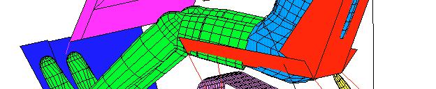
58 automotive engineering & product design
59 automotive engineering & product design The following restraint parameters with current values must be optimized for minimal OSI value: Belt feed (pull out distance of belt before locking), 6% (2 mm). yes / no Belt pretensioner (pyrotechnic tightening of the belt), pull in distance vs. time curve (15 mm pull in at 12 ms). yes / no Spool effect, belt force vs. outlet curve (12 kn = 12 mm). + / - 25 % Belt strain, belt force vs. strain curve (3 kn = 18.3 % elongation). + / - 25 % Airbag delay time (activation time after collision start), 15 ms. + / - 1 ms Airbag stream out surface, mm 2. + / - 25 % Airbag mass flow, curve of mass flow dependent on inflation time. + / - 25 %
60 automotive engineering & product design The demands for a realistic crash index are formulated as follows: 1. Some injury types are more important than others. 2. Improvements in high valued injury criteria count more than improvements in already low valued criteria. 3. If one injury type has a much higher value with respect to its limited value than the other criteria, then an improvement on this higher value must be count additionally. 4. The improvement in one injury type counts less than the improvement of several injuries types. 5. A large improvement in an injury type counts more than a small one.
61 automotive engineering & product design Relevant injury criteria with their by legislation limited values. Injury Criterion HIC CHEST-G CHEST-D FEMUR-F NECK-M Limit value 1 6 g 5 mm 1 N 189 Nm Weight factor The Overall Severity Index (OSI) is given by the following formulae: (HICmod HIC ref) OSI * HIC ref HIC HIC * HICref = HIC * TOTREF *8 + lim lim lim (CHEST.Gmod CHEST.G ref) * CHEST.G ref CHEST.G CHEST.G * CHEST.Gref CHEST.G * TOTREF *2 + lim lim lim (CHEST.Dmod CHEST.D ref) * CHEST.D ref CHEST.D CHEST.D * CHEST.Dref CHEST.D * TOTREF *2 + lim lim lim (FEMUR.Fmod FEMUR.F ref) * FEMUR.F ref FEMUR.F FEMUR.F * FEMUR.Fref lim lim FEMUR.Flim *TOTREF *1 + (NECK.Mmod NECK.M ref) ref ref * NECK.M NECK.Mlim NECK.M * NECK.M lim NECK.M lim * TOTREF * 2 * where HICref CHEST.Gref CHEST.Dref FEMUR.Fref NECK.M TOTREF = HIClim CHEST.Glim CHEST.Dlim FEMUR.Flim NECK.M ref lim
62 automotive engineering & product design ] /h m y [k e l o cit n [ g ],v a r t io e l e c d Reference pulse OSI = 1 Velocity time [ms ]
63 automotive engineering & product design ] /h m y [k e l o cit g n [ ],v a r t io e l e c d h m / ] [k e l o city g n [ ],v a r t io e l e c d 6 5 Pulse V56-1 Velocity OSI=143.3 Pulse V56-3 Velocity OSI=136.9 ] /h m y [k e l o cit g n [ ],v a r t io e l e c d h m / ] [k e l o city g n [ ],v a r t io e l e c d 6 5 Pulse V56-2 Velocity OSI=18.6 Pulse V56-4 Velocity OSI= Four examples of other possible crash pulses.
64 R e fe r e n c e p u ls e automotive engineering & product design mm/ms2 mm/ms2 mm kn mm kn M a g n i tu d e ( S a e 1 8 _ 5 ( A c c e le r a ti o n [ ]) H IC ) ) H IC = T im e [m s ] R e fe r e n c e p u ls e M a g n i tu d e ( S a e 1 8 _ 5 ( A c c e le r a ti o n [ ]) M S ) ) C H E S T G = T im e [m s ] C H E S T D = R e fe r e n c e p u ls e B a r A x ia l E lo n g a t io n [5 3 t/ m ] T im e [m s ] R e fe r e n c e p u ls e S a e 1 8 _ 5 ( S P R IN G L o c a l F o r c e - M a g n it u d e [ ] = -. S a e 1 8 _ 5 ( S P R IN G L o c a l F o r c e - M a g n it u d e [ ] = - F E M U R F = T im e [m s ] R e fe r e n c e p u ls e N E C K M = S a e 1 8 _ 5 ( S p h e r e J o in t M o m e n t a b o u t [9 2 1 ] T im e [m s ] HIC CHEST-G CHEST-D FEMUR-F NECK-M HIC = 284 (limit 1) CHEST-G = 35 g (limit 6 g) CHEST-D = 27 mm (limit 5 mm) FEMUR-F = 3984 N (limit 1. N) NECK-M = 33 Nm (limit 189 Nm)
65 Reference Pulse V56-5 Veloc ity Referenc e Pulse V56-6 Velocity automotive engineering & product design OSI=93.8 OSI=94. ] /h m y [k e l o cit n [ g ],v ra t io e l e c d ] /h m y [k e l o cit n [ g ],v ra t io e l e c d time [ms ] Reference Pulse V56-7 Veloc ity time [ms ] ] /h m y [k e l o cit n [ g ],v ra t io e l e c d ] /h m y [k e l o cit n [ g ],v ra t io e l e c d time [ms ] Referenc e Pulse V56-8 Velocity time [ms ] OSI=16.9 OSI=13.1 Reference Pulse V56-9 Veloc ity Referenc e Pulse V56-1 Velocity OSI=11.1 ] /h m y [k e l o cit n [ g ],v ra t io e l e c d time [ms ] ] /h m y [k e l o cit n [ g ],v ra t io e l e c d time [ms ] OSI=98.6
66 automotive engineering & product design OSI=94.4 ] /h m y [k e l o cit g n [ ],v a r t io e l e c d OSI=93.5 ] /h m y [k e l o cit g n [ ],v a r t io e l e c d Ref. V56-5 Puls e V56-12 Veloc ity Ref. V56-5 Puls e V56-11 Veloc ity time [ms ] ] /h m y [k e l o cit g n [ ],v a r t io e l e c d OSI=96. Ref. V56-5 Puls e V56-13 Veloc ity time [ms ] time [ms ]
67 automotive engineering & product design OSI=92.6 h m / ] [k e l o city g n [ ],v a r t io e l e c d OSI=1.1 h m / ] [k e l o city g n [ ],v a r t io e l e c d Ref. V56-11 Puls e V56-15 Veloc ity Ref. V56-11 Puls e V56-14 Veloc ity time [ms ] h m / ] [k e l o city g n [ ],v a r t io e l e c d OSI=97.4 Ref. V56-11 Puls e V56-16 Veloc ity time [ms ] time [ms ]
68 automotive engineering & product design ] /h m y [k e l o cit g n [ ],v a r t io e l e c d ] /h m y [k e l o cit g n [ ],v a r t io e l e c d 6 5 Ref. V56-11 Puls e V56-17 Veloc ity time [ms ] Ref. V56-11 Puls e V56-19 Veloc ity OSI=93.6 OSI=94.6 ] /h m y [k e l o cit g n [ ],v a r t io e l e c d ] /h m y [k o cit e l ],v [g n a r t io e l e c d 6 5 Ref. V56-11 Puls e V56-18 Veloc ity time [ms ] Ref. V56-11 Puls e V56-2 Veloc ity OSI=97.3 OSI=
69 Start reference Optimized Velocity OSI=1 OSI= automotive engineering & product design deceleration [g], velocity [km/h]
70 Reference pulse Pulse-V automotive engineering & product design HIC 284 CHEST-G 35 CHEST-D 27 FEMUR-F mm mm/ms2 mm/ms2 kn Magnitude(Sae18_5(Acceleration[8511]) HIC )) HIC= Tim e [m s ] Reference pulse Magnitude(Sae18_5(Acceleration[8531]) MS )) CHESTG= Tim e [m s ] Reference pulse Bar Axial Elongation [53 t/m 536] C H E S T D = Tim e [m s ] Reference pulse Sae18_5(SPRING Local Force-Magnitude [9141] = -. 7 Sae18_5(SPRING Local Force-Magnitude [9181] = - FEMURF= mm mm/ms2 mm/ms2 kn Magnitude(S ae18_5(acceleration[8511]) HIC )) HIC= Tim e [m s ] P ulse-v Magnitude(Sae18_5(Acceleration[8531]) MS )) C HES TG= Tim e [m s] P ulse-v56-15 Bar Axial Elongation [53 t/m 536] C HESTD= Tim e [m s] P ulse-v56-15 Sae18_5(SP RING Local Force-Magnitude [9141] = -. 7 Sae18_5(SP RING Local Force-Magnitude [9181] = - FEMURF= HIC 251 CHEST-G 31 CHEST-D 21 FEMUR-F Tim e [m s ] Tim e [m s] 16 Reference pulse 9 P ulse-v56-15 NECK-M 33 kn mm kn mm NECK-M 29 NE C KM=32.77 Sae18_5(SphereJoint Moment about [921] Tim e [m s ] NECKM=28.92 Sae18_5(SphereJoint Moment about [921] Tim e [m s]
71 automotive engineering & product design ] /h m y [k e l o cit g n [ ],v a r t io e l e c d Ref. V56-15 Puls e V56-21 Veloc ity HIC=251, CHEST-G=31, CHEST-D=21, FEMUR-F=566, NECK-M=29 OSI=92.6 HIC=315, CHEST-G=39, CHEST-D=22, FEMUR-F=417, NECK-M=34 OSI=11.4
72 automotive engineering & product design m ] [N -M N eck Without airbag up to 28 W ith air b a g velocity [km/h] The Neck-M for other velocities.
73 automotive engineering & product design
74 automotive engineering & product design m /h] k y [ o cit e l v km/h 64 km/h 32 km/h OSI=1 OSI=11 OSI=8 45g 32g 9g 9g 9g 23g 23g 9g deformation length [cm] Three optimal decelerations curves in three phases.

75 automotive engineering & product design
ADAPTIVE FRONTAL STRUCTURE DESIGN TO ACHIEVE OPTIMAL DECELERATION PULSES
 ADAPTIVE FRONTAL STRUCTURE DESIGN TO ACHIEVE OPTIMAL DECELERATION PULSES Willem Witteman Technische Universiteit Eindhoven Mechanics of Materials/Vehicle Safety The Netherlands Paper Number 05-0243 ABSTRACT
Full Width Test ECE-R 94 Evaluation of test data Proposal for injury criteria Way forward
 Full Width Test ECE-R 94 Evaluation of test data Proposal for injury criteria Way forward Andre Eggers IWG Frontal Impact 19 th September, Bergisch Gladbach Federal Highway Research Institute BASt Project
Injury Risk and Seating Position for Fifth-Percentile Female Drivers Crash Tests with 1990 and 1992 Lincoln Town Cars. Michael R. Powell David S.
 Injury Risk and Seating Position for Fifth-Percentile Female Drivers Crash Tests with 1990 and 1992 Lincoln Town Cars Michael R. Powell David S. Zuby July 1997 ABSTRACT A series of 35 mi/h barrier crash
STUDY ON CAR-TO-CAR FRONTAL OFFSET IMPACT WITH VEHICLE COMPATIBILITY
 STUDY ON CAR-TO-CAR FRONTAL OFFSET IMPACT WITH VEHICLE COMPATIBILITY Chang Min, Lee Jang Ho, Shin Hyun Woo, Kim Kun Ho, Park Young Joon, Park Hyundai Motor Company Republic of Korea Paper Number 17-0168
Methodologies and Examples for Efficient Short and Long Duration Integrated Occupant-Vehicle Crash Simulation
 13 th International LS-DYNA Users Conference Session: Automotive Methodologies and Examples for Efficient Short and Long Duration Integrated Occupant-Vehicle Crash Simulation R. Reichert, C.-D. Kan, D.
FINITE ELEMENT METHOD IN CAR COMPATIBILITY PHENOMENA
 Journal of KONES Powertrain and Transport, Vol. 18, No. 4 2011 FINITE ELEMENT METHOD IN CAR COMPATIBILITY PHENOMENA Marcin Lisiecki Technical University of Warsaw Faculty of Power and Aeronautical Engineering
Pre impact Braking Influence on the Standard Seat belted and Motorized Seat belted Occupants in Frontal Collisions based on Anthropometric Test Dummy
 Pre impact Influence on the Standard Seat belted and Motorized Seat belted Occupants in Frontal Collisions based on Anthropometric Test Dummy Susumu Ejima 1, Daisuke Ito 1, Jacobo Antona 1, Yoshihiro Sukegawa
ARE SMALL FEMALES MORE VULNERABLE TO LOWER NECK INJURIES WHEN SEATED SUFFICIENTLY AWAY FROM THE STEERING WHEEL IN A FRONTAL CRASH?
 ARE SMALL FEMALES MORE VULNERABLE TO LOWER NECK INJURIES WHEN SEATED SUFFICIENTLY AWAY FROM THE STEERING WHEEL IN A FRONTAL CRASH? Chandrashekhar Simulation Technologies LLC United States Paper Number
D1.3 FINAL REPORT (WORKPACKAGE SUMMARY REPORT)
") WP 1 D1.3 FINAL REPORT (WORKPACKAGE SUMMARY REPORT) Project Acronym: Smart RRS Project Full Title: Innovative Concepts for smart road restraint systems to provide greater safety for vulnerable road users.
WP 1 D1.3 FINAL REPORT (WORKPACKAGE SUMMARY REPORT) Project Acronym: Smart RRS Project Full Title: Innovative Concepts for smart road restraint systems to provide greater safety for vulnerable road users.
Convertible with unique safety features
 PRESS INFORMATION The all new Volvo C70 Safety Convertible with unique safety features Volvo s Unique Side Impact Protection System (SIPS) interacts with world-first door-mounted inflatable curtain for
Wheelchair Transportation Principles I: Biomechanics of Injury
 Wheelchair Transportation Principles I: Biomechanics of Injury Gina Bertocci, Ph.D. & Douglas Hobson, Ph.D. Department of Rehabilitation Science and Technology University of Pittsburgh This presentation
Real World Accident Reconstruction with the Total Human Model for Safety (THUMS) in Pam-Crash
 in Pam-Crash") Real World Accident Reconstruction with the Total Human Model for Safety (THUMS) in Pam-Crash R Segura 1,2, F Fürst 2, A Langner 3 and S Peldschus 4 1 Arbeitsgruppe Biomechanik, Institute of Legal Medicine,
Real World Accident Reconstruction with the Total Human Model for Safety (THUMS) in Pam-Crash R Segura 1,2, F Fürst 2, A Langner 3 and S Peldschus 4 1 Arbeitsgruppe Biomechanik, Institute of Legal Medicine,
THUMS User Community
 THUMS User Community Therese Fuchs, Biomechanics Group, Institute of Legal Medicine, University of Munich therese.fuchs@med.uni-muenchen.de, tel. +49 89 2180 73365 Munich, 9th of April 2014 Agenda 1. What
Crash test facility simulates frontal, rear-end and side collision with acceleration pulses of up to 65 g and 85 km/h (53 mph)
") Johnson Controls invests 3 million Euro (2.43 million GBP) in state-of-theart crash test facility Crash test facility simulates frontal, rear-end and side collision with acceleration pulses of up to 65
Johnson Controls invests 3 million Euro (2.43 million GBP) in state-of-theart crash test facility Crash test facility simulates frontal, rear-end and side collision with acceleration pulses of up to 65
Surviving a Crash in Rear Seats: Addressing the Needs from a Diverse Population
 Surviving a Crash in Rear Seats: Addressing the Needs from a Diverse Population Jingwen Hu, PhD UMTRI-Biosciences MADYMO USER MEETING 2016 Research Themes Safety Design Optimization Laboratory Testing
Virtual human body model for fast safety assessment
 Virtual human body model for fast safety assessment Luděk Hynčík et al. Luděk Kovář el al. University of West Bohemia MECAS ESI s.r.o. Plzeň (Pilsen), Czech Republic AUTOSYMPO 2017 31 October 2 November
ABSTRACT INTRODUCTION
 SIMULATION OF TRUCK REAR UNDERRUN BARRIER IMPACT Roger Zou*, George Rechnitzer** and Raphael Grzebieta* * Department of Civil Engineering, Monash University, ** Accident Research Centre, Monash University,
DESIGN FOR CRASHWORTHINESS
 - The main function of the body structure is to protect occupants in a collision - There are many standard crash tests and performance levels - For the USA, these standards are contained in Federal Motor
FIMCAR. Frontal Impact Assessment Approach FIMCAR. frontal impact and compatibility assessment research
 FIMCAR Frontal Impact Assessment Approach FIMCAR Prof. Dr., Dr. Mervyn Edwards, Ignacio Lazaro, Dr. Thorsten Adolph, Ton Versmissen, Dr. Robert Thomson EC funded project ended September 2012 Partners:
An Evaluation of Active Knee Bolsters
 8 th International LS-DYNA Users Conference Crash/Safety (1) An Evaluation of Active Knee Bolsters Zane Z. Yang Delphi Corporation Abstract In the present paper, the impact between an active knee bolster
Development of Advanced HIII Abaqus dummies
 Visit the SIMULIA Resource Center for more customer examples. Development of Advanced HIII Abaqus dummies W. Li, J. Rasico, F. Zhu, M. Li, R. Kant, B. Aljundi First Technology Safety System Inc. Abstract:
SLED TEST PROCEDURE FOR ASSESSING KNEE IMPACT AREAS
 EUROPEAN NEW CAR ASSESSMENT PROGRAMME (Euro NCAP) SLED TEST PROCEDURE FOR ASSESSING KNEE IMPACT AREAS CONTENTS 1 INTRODUCTION...2 2 PREREQUISITES FOR KNEE MAPPING...3 3 HARDWARE SETUP...4 4 VALIDATION
Potential Effects of Deceleration Pulse Variations on Injury Measures Computed in Aircraft Seat HIC Analysis Testing
 Potential Effects of Deceleration Pulse Variations on Injury Measures Computed in Aircraft Seat HIC Analysis Testing K Friedman, G Mattos, K Bui, J Hutchinson, and A Jafri Friedman Research Corporation
Lateral Protection Device
 V.5 Informal document GRSG-113-11 (113th GRSG, 10-13 October 2017, agenda item 7.) Lateral Protection Device France Evolution study on Regulation UNECE n 73 1 Structure Accidentology analysis Regulation
Study on the Influence of Seat Adjustment on Occupant Head Injury Based on MADYMO
 5th International Conference on Advanced Engineering Materials and Technology (AEMT 2015) Study on the Influence of Seat Adjustment on Occupant Head Injury Based on MADYMO Shucai Xu 1, a *, Binbing Huang
Australian Pole Side Impact Research 2010
 Australian Pole Side Impact Research 2010 A summary of recent oblique, perpendicular and offset perpendicular pole side impact research with WorldSID 50 th Thomas Belcher (presenter) MarkTerrell 1 st Meeting
INFLUENCE OF BUMPER DESIGN TO LOWER LEG IMPACT RESPONSE
 F2006SC05 INFLUENCE OF BUMPER DESIGN TO LOWER LEG IMPACT RESPONSE Svoboda Jiri*, Kuklik Martin Czech Technical University in Prague, Faculty of Mechanical Engineering, Department of Automotive and Aerospace
Insert the title of your presentation here. Presented by Name Here Job Title - Date
 Insert the title of your presentation here Presented by Name Here Job Title - Date Automatic Insert the triggering title of your of emergency presentation calls here Matthias Presented Seidl by Name and
EVALUATION OF MOVING PROGRESSIVE DEFORMABLE BARRIER TEST METHOD BY COMPARING CAR TO CAR CRASH TEST
 EVALUATION OF MOVING PROGRESSIVE DEFORMABLE BARRIER TEST METHOD BY COMPARING CAR TO CAR CRASH TEST Shinsuke, Shibata Azusa, Nakata Toru, Hashimoto Honda R&D Co., Ltd. Automobile R&D Center Japan Paper
Using the Abaqus BioRID-II Dummy to support the development of a Front Seat Structure during rear low speed crashes - Whiplash
 Using the Abaqus BioRID-II Dummy to support the development of a Front Seat Structure during rear low speed crashes - Whiplash H.Hartmann (1), M. Socko (2) (1) Faurecia Autositze GmbH, (2) Faurecia Fotele
Side Impact and Ease of Use Comparison between ISOFIX and LATCH. CLEPA Presentation to GRSP, Informal Document GRSP Geneva, May 2004
 Side Impact and Ease of Use Comparison between ISOFIX and LATCH CLEPA Presentation to GRSP, Informal Document GRSP- 35-1 9 Geneva, May 2004 1 Objective of test programme To objectively assess the comparison
White Paper. Compartmentalization and the Motorcoach
 White Paper Compartmentalization and the Motorcoach By: SafeGuard, a Division of IMMI April 9, 2009 Table of Contents Introduction 3 Compartmentalization in School Buses...3 Lap-Shoulder Belts on a Compartmentalized
Study concerning the loads over driver's chests in car crashes with cars of the same or different generation
 IOP Conference Series: Materials Science and Engineering PAPER OPEN ACCESS Study concerning the loads over driver's chests in car crashes with cars of the same or different generation Related content -
Finite Element Modeling and Analysis of Crash Safe Composite Lighting Columns, Contact-Impact Problem
 9 th International LS-DYNA Users Conference Impact Analysis (3) Finite Element Modeling and Analysis of Crash Safe Composite Lighting Columns, Contact-Impact Problem Alexey Borovkov, Oleg Klyavin and Alexander
Crash Simulation in Pedestrian Protection
 4 th European LS-DYNA Users Conference Occupant II / Pedestrian Safety Crash Simulation in Pedestrian Protection Authors: Susanne Dörr, Hartmut Chladek, Armin Huß Ingenieurbüro Huß & Feickert Correspondence:
LEG PROTECTION FOR MOTORCYCLISTS. B. P. Chinn T.R.R.L. M.A. Macaulay Brunel University
 LEG PROTECTION FOR MOTORCYCLISTS B. P. Chinn T.R.R.L. M.A. Macaulay Brunel University 1. Introduction A number of earlier papers by Chinn and Macaulay (1), Chinn, Hopes and Macaulay (2) and Macaulay and
Performance as Test Procedures of the PDB and ODB Tests for a Mini-Car
 FI-3-11 Performance as Test Procedures of the PDB and ODB Tests for a Mini-Car JAPAN December 9, 2008 3rd Meeting of the Informal Group on Frontal Impact 1 Objective To examine effects on mini-cars when
Development of Rattle Noise Analysis Technology for Column Type Electric Power Steering Systems
 TECHNICAL REPORT Development of Rattle Noise Analysis Technology for Column Type Electric Power Steering Systems S. NISHIMURA S. ABE The backlash adjustment mechanism for reduction gears adopted in electric
EVALUATION OF VEHICLE-BASED CRASH SEVERITY METRICS USING EVENT DATA RECORDERS
 EVALUATION OF VEHICLE-BASED CRASH SEVERITY METRICS USING EVENT DATA RECORDERS Grace Wusk Hampton Gabler Virginia Tech United States Paper Number 17-0407 ABSTRACT Injury risk in real world crashes is often
NUMERICAL ANALYSIS OF IMPACT BETWEEN SHUNTING LOCOMOTIVE AND SELECTED ROAD VEHICLE
 Journal of KONES Powertrain and Transport, Vol. 21, No. 4 2014 ISSN: 1231-4005 e-issn: 2354-0133 ICID: 1130437 DOI: 10.5604/12314005.1130437 NUMERICAL ANALYSIS OF IMPACT BETWEEN SHUNTING LOCOMOTIVE AND
Digges 1 INJURIES TO RESTRAINED OCCUPANTS IN FAR-SIDE CRASHES. Kennerly Digges The Automotive Safety Research Institute Charlottesville, Virginia, USA
 INJURIES TO RESTRAINED OCCUPANTS IN FAR-SIDE CRASHES Kennerly Digges The Automotive Safety Research Institute Charlottesville, Virginia, USA Dainius Dalmotas Transport Canada Ottawa, Canada Paper Number
HEAD AND NECK INJURY POTENTIAL IN INVERTED IMPACT TESTS
 HEAD AND NECK INJURY POTENTIAL IN INVERTED IMPACT TESTS Steve Forrest Steve Meyer Andrew Cahill SAFE Research, LLC United States Brian Herbst SAFE Laboratories, LLC United States Paper number 07-0371 ABSTRACT
Analysis of a Frontal Impact of a Formula SAE Vehicle David Rising Jason Kane Nick Vernon Joseph Adkins Dr. Craig Hoff Dr. Janet Brelin-Fornari
 Analysis of a Frontal Impact of a Formula SAE Vehicle David Rising Jason Kane Nick Vernon Joseph Adkins Dr. Craig Hoff Dr. Janet Brelin-Fornari Kettering University Overview Introduction Formula SAE Impact
Small Overlap Frontal Crashworthiness Evaluation Rating Protocol (Version II)
") Small Overlap Frontal Crashworthiness Evaluation Rating Protocol (Version II) Rating Guidelines for Restraints and Dummy Kinematics, Injury Measures, and Vehicle Structural Performance Weighting Principles
Small Overlap Frontal Crashworthiness Evaluation Rating Protocol (Version II) Rating Guidelines for Restraints and Dummy Kinematics, Injury Measures, and Vehicle Structural Performance Weighting Principles
SEAT BELTS AND AIRBAGS. Mercedes-Benz
 SEAT BELTS AND AIRBAGS Mercedes-Benz Competence in Safety. Safety is indivisible. Mercedes-Benz has been passionate about making cars each one even better than the last from day one. Since the first model
ANALYTICAL EVALUATION OF AN ADVANCED INTEGRATED SAFETY SEAT DESIGN IN FRONTAL, REAR, SIDE, AND ROLLOVER CRASHES
 ANALYTICAL EVALUATION OF AN ADVANCED INTEGRATED SAFETY SEAT DESIGN IN FRONTAL, REAR, SIDE, AND ROLLOVER CRASHES Mostafa Rashidy, Balachandra Deshpande, Gunasekar T.J., Russel Morris EASi Engineering Robert
Folksam bicycle helmets for children test report 2017
 2017 Folksam bicycle helmets for children test report 2017 Summary Folksam has tested nine bicycle helmets on the Swedish market for children. All helmets included in the test have previously been tested
Crashworthiness Evaluation of an Impact Energy Absorber in a Car Bumper for Frontal Crash Event - A FEA Approach
 Crashworthiness Evaluation of an Impact Energy Absorber in a Car Bumper for Frontal Crash Event - A FEA Approach Pravin E. Fulpagar, Dr.S.P.Shekhawat Department of Mechanical Engineering, SSBTS COET Jalgaon.
PRODUCT DESCRIPTION. X-Tension DS. is suitable for all road types: Motorways, country roads, city streets for speed categories up to 110 km/h.
 INDEX Introduction 2 Product Description 3 Installation 6 Specifications 7 Crash Tests Table 8 Reusability 9 FAQ 10 Annexes 14 Drawings 15 Pictures 16 Crash Tests Results 18 Approvals 23 INTRODUCTION Improving
An Analysis of Less Hazardous Roadside Signposts. By Andrei Lozzi & Paul Briozzo Dept of Mechanical & Mechatronic Engineering University of Sydney
 An Analysis of Less Hazardous Roadside Signposts By Andrei Lozzi & Paul Briozzo Dept of Mechanical & Mechatronic Engineering University of Sydney 1 Abstract This work arrives at an overview of requirements
THE INFLUENCE OF THE SAFETY BELT ON THE DECISIVE INJURY ASSESSMENT VALUES IN THE NEW US-NCAP
 THE INFLUENCE OF THE SAFETY BELT ON THE DECISIVE INJURY ASSESSMENT VALUES IN THE NEW US-NCAP Burkhard Eickhoff*, Harald Zellmer*, Martin Meywerk** *Autoliv B.V. & Co. KG, Elmshorn, Germany **Helmut-Schmidt-Universität,
SPCT Method. The SPCT Method - Testing of Dog Crates. Utskrivet dokument är ostyrt, dvs inte säkert gällande.
 Kvalitetsdokument Författare, enhet Mikael Videby Bygg och Mekanik Hållfasthet och konstruktion Utgåva 1 (7) Godkännare 2 The Testing of Dog Crates Application Area... 2 References... 2 1 Test Sample Selection...
Folksam Mazda 6 Post-Impact Inspection 22/02/18
 Offset Deformable Barrier Frontal Impact Dummy Score 2003 Test at TRL Driver Passenger Score (worst) 11 2018 Test at Thatcham Score (worst) 12.289 Modifier Score Reason Head airbag contact Bottoming out
Stakeholder Meeting: FMVSS Considerations for Automated Driving Systems
 Stakeholder Meeting: FMVSS Considerations for Automated Driving Systems 200-Series Breakout Sessions 1 200-Series Breakout Session Focus Panel Themes 201 202a 203 204 205 206 207 208 210 214 216a 219 222
Skid against Curb simulation using Abaqus/Explicit
 Visit the SIMULIA Resource Center for more customer examples. Skid against Curb simulation using Abaqus/Explicit Dipl.-Ing. A. Lepold (FORD), Dipl.-Ing. T. Kroschwald (TECOSIM) Abstract: Skid a full vehicle
Safer Vehicle Design. TRIPP IIT Delhi
 Safer Vehicle Design S. Mukherjee TRIPP IIT Delhi Why a risk Five horsepower Kinetic energy of about 1 KiloJoules The operator undergoes three years of fulltime training wear helmets eyeglasses their skills
Design Evaluation of Fuel Tank & Chassis Frame for Rear Impact of Toyota Yaris
 International Research Journal of Engineering and Technology (IRJET) e-issn: 2395-0056 Volume: 03 Issue: 05 May-2016 p-issn: 2395-0072 www.irjet.net Design Evaluation of Fuel Tank & Chassis Frame for Rear
CLIENT PROJECT REPORT
 Transport Research Laboratory Technical Assistance and Economic Analysis in the Field of Legislation Pertinent to the Issue of Automotive Safety: Provision of information and services on the subject of
Correlation of Occupant Evaluation Index on Vehicle-occupant-guardrail Impact System Guo-sheng ZHANG, Hong-li LIU and Zhi-sheng DONG
 07 nd International Conference on Computer, Mechatronics and Electronic Engineering (CMEE 07) ISBN: 978--60595-53- Correlation of Occupant Evaluation Index on Vehicle-occupant-guardrail Impact System Guo-sheng
ADVANCED RESTRAINT SY S STEM (ARS) Y Stephen Summers St NHTSA Ve NHTSA V hi hhicle S Saf t e y t R Resear R h c 1
 Y Stephen Summers St NHTSA Ve NHTSA V hi hhicle S Saf t e y t R Resear R h c 1") ADVANCED RESTRAINT SYSTEM (ARS) Stephen Summers NHTSA Vehicle Safety Research 1 CRASH AVOIDANCE METRICS PARTNERSHIP (CAMP) ARS 4 year Cooperative research program Demonstrate restraint systems that can
ADVANCED RESTRAINT SYSTEM (ARS) Stephen Summers NHTSA Vehicle Safety Research 1 CRASH AVOIDANCE METRICS PARTNERSHIP (CAMP) ARS 4 year Cooperative research program Demonstrate restraint systems that can
REDUCING RIB DEFLECTION IN THE IIHS TEST BY PRELOADING THE PELVIS INDEPENDENT OF INTRUSION
 REDUCING RIB DEFLECTION IN THE IIHS TEST BY PRELOADING THE PELVIS INDEPENDENT OF INTRUSION Greg Mowry David Shilliday Zodiac Automotive US. Inc. United States Paper Number 5-422 ABSTRACT A cooperative
Development and Validation of a Finite Element Model of an Energy-absorbing Guardrail End Terminal
 Development and Validation of a Finite Element Model of an Energy-absorbing Guardrail End Terminal Yunzhu Meng 1, Costin Untaroiu 1 1 Department of Biomedical Engineering and Virginia Tech, Blacksburg,
Simulation and Validation of FMVSS 207/210 Using LS-DYNA
 7 th International LS-DYNA Users Conference Simulation Technology (2) Simulation and Validation of FMVSS 207/210 Using LS-DYNA Vikas Patwardhan Tuhin Halder Frank Xu Babushankar Sambamoorthy Lear Corporation
EUROPEAN NEW CAR ASSESSMENT PROGRAMME (Euro NCAP) ASSESSMENT PROTOCOL PEDESTRIAN PROTECTION
 ASSESSMENT PROTOCOL PEDESTRIAN PROTECTION") EUROPEAN NEW CAR ASSESSMENT PROGRAMME (Euro NCAP) ASSESSMENT PROTOCOL PEDESTRIAN PROTECTION Version 8.1 Copyright Euro NCAP 2015 - This work is the intellectual property of Euro NCAP. Permission is granted
EUROPEAN NEW CAR ASSESSMENT PROGRAMME (Euro NCAP) ASSESSMENT PROTOCOL PEDESTRIAN PROTECTION Version 8.1 Copyright Euro NCAP 2015 - This work is the intellectual property of Euro NCAP. Permission is granted
Strength Analysis of Seat Belt Anchorage According to ECE R14 and FMVSS
 4 th European LS-DYNA Users Conference Crash / Automotive Applications II Strength Analysis of Seat Belt Anchorage According to ECE R14 and FMVSS Author: Klaus Hessenberger DaimlerChrysler AG,Stuttgart,
ROLLOVER CRASHWORTHINESS OF A RURAL TRANSPORT VEHICLE USING MADYMO
 ROLLOVER CRASHWORTHINESS OF A RURAL TRANSPORT VEHICLE USING MADYMO S. Mukherjee, A. Chawla, A. Nayak, D. Mohan Indian Institute of Technology, New Delhi INDIA ABSTRACT In this work a full vehicle model
Transmission Error in Screw Compressor Rotors
 Purdue University Purdue e-pubs International Compressor Engineering Conference School of Mechanical Engineering 2008 Transmission Error in Screw Compressor Rotors Jack Sauls Trane Follow this and additional
EUROPEAN NEW CAR ASSESSMENT PROGRAMME (Euro NCAP)
") EUROPEAN NEW CAR ASSESSMENT PROGRAMME (Euro NCAP) ASSESSMENT PROTOCOL ADULT OCCUPANT PROTECTION Implementation 1 st January 2020 Copyright 2018 Euro NCAP - This work is the intellectual property of Euro
EUROPEAN NEW CAR ASSESSMENT PROGRAMME (Euro NCAP) ASSESSMENT PROTOCOL ADULT OCCUPANT PROTECTION Implementation 1 st January 2020 Copyright 2018 Euro NCAP - This work is the intellectual property of Euro
Lighter and Safer Cars by Design
 Lighter and Safer Cars by Design May 2013 DRI Compatibility Study (2008) Modern vehicle designs - generally good into fixed barriers irrespective of vehicle type or material Safety discussion is really
Analysis of minimum train headway on a moving block system by genetic algorithm Hideo Nakamura. Nihon University, Narashinodai , Funabashi city,
 Analysis of minimum train headway on a moving block system by genetic algorithm Hideo Nakamura Nihon University, Narashinodai 7-24-1, Funabashi city, Email: nakamura@ecs.cst.nihon-u.ac.jp Abstract A minimum
CMVSR 208 OCCUPANT RESTRAINT SYSTEMS IN FRONTAL IMPACT
 CMVSR 208 OCCUPANT RESTRAINT SYSTEMS IN FRONTAL IMPACT revised: 2014-09-12 LEGEND FAS: A & LB: LB: : DSP Fully Automatic System Automatic plus Lap Belt Lap Belt Lap Belt plus Shoulder Belt Lap Shoulder
Small Overlap Frontal Crashworthiness Evaluation
 Small Overlap Frontal Crashworthiness Evaluation Rating Protocol (Version IV) Rating Guidelines for Restraints and Dummy Kinematics, Injury Measures, and Vehicle Structural Performance Weighting Principles
NORDAC 2014 Topic and no NORDAC
 NORDAC 2014 Topic and no NORDAC 2014 http://www.nordac.net 8.1 Load Control System of an EV Charging Station Group Antti Rautiainen and Pertti Järventausta Tampere University of Technology Department of
FIMCAR Accident Analysis Report to GRSP frontal impact IWG Summary of findings
 FIMCAR Accident Analysis Report to GRSP frontal impact IWG Summary of findings Mervyn Edwards, Alex Thompson, Thorsten Adolph, Rob Thomson, Aleksandra Krusper October 14 th 2010 Objectives Determine if
E/ECE/324/Rev.2/Add.128/Rev.1/Amend.2 E/ECE/TRANS/505/Rev.2/Add.128/Rev.1/Amend.2
 E/ECE/324/Rev.2/Add.128/Rev.1/Amend.2 26 July 2017 Agreement Concerning the Adoption of Uniform Technical Prescriptions for Wheeled Vehicles, Equipment and Parts which can be Fitted and/or be Used on Wheeled
ROBUST PROJECT Norwegian Public Roads Administration / Force Technology Norway AS
 ROBUST PROJECT Norwegian Public Roads Administration / Force Technology Norway AS Evaluation of small car - RM_R1 - prepared by Politecnico di Milano Volume 1 of 1 January 2006 Doc. No.: ROBUST-5-002/TR-2004-0039
Presentation of the draft Global Technical Regulation on Safety Belts
 Informal Document N 18 (30th GRSP, 3-6 December 2001 Agenda item 1.3.4) November 28 th, 2001 Presentation of the draft Global Technical Regulation on Safety Belts The draft global technical regulation
EEVC Report to EC DG Enterprise Regarding the Revision of the Frontal and Side Impact Directives January 2000
 EEVC Report to EC DG Enterprise Regarding the Revision of the Frontal and Side Impact Directives January 2000 EEVC Report to EC DG Enterprise Regarding the Revision of the Frontal and Side Impact Directives
VW Passat VW Passat 2.0 TDI 'Comfortline', LHD
 VW Passat VW Passat 2.0 TDI 'Comfortline', LHD 85% 87% 66% 76% DETAILS OF TESTED CAR SPECIFICATIONS Tested model VW Passat 2.0 TDI 'Comfortline', LHD Body type 5 door hatchback Year of publication 2014
LEVER OPTIMIZATION FOR TORQUE STANDARD MACHINES
 LEVER OPTIMIZATION FOR TORQUE STANDARD MACHINES D. Röske, K. Adolf and D. Peschel Torque laboratory Division for Mechanics and Acoustics Phys.-Techn. Bundesanstalt, D-38116 Braunschweig, Germany Abstract:
Jeong <1> Development of a Driver-side Airbag Considering Autonomous Emergency Braking
 Development of a Driver-side Airbag Considering Autonomous Emergency Braking Garam, Jeong Hae Kwon, Park Kyu Sang, Lee Seok hoon, Ko Heonjung, Choo Hyo Bae, Lee Hyundai Mobis CO., Ltd Korea, South Paper
EUROPEAN NEW CAR ASSESSMENT PROGRAMME (Euro NCAP) ASSESSMENT PROTOCOL PEDESTRIAN PROTECTION
 ASSESSMENT PROTOCOL PEDESTRIAN PROTECTION") EUROPEAN NEW CAR ASSESSMENT PROGRAMME (Euro NCAP) ASSESSMENT PROTOCOL PEDESTRIAN PROTECTION Version 9.0.2 Version 9.0.2 EUROPEAN NEW CAR ASSESSMENT PROGRAMME (Euro NCAP) ASSESSMENT PROTOCOL PEDESTRIAN
EUROPEAN NEW CAR ASSESSMENT PROGRAMME (Euro NCAP) ASSESSMENT PROTOCOL PEDESTRIAN PROTECTION Version 9.0.2 Version 9.0.2 EUROPEAN NEW CAR ASSESSMENT PROGRAMME (Euro NCAP) ASSESSMENT PROTOCOL PEDESTRIAN
OPTIMIZATION SEAT OF BACK REST OF A CAR
 Int. J. Mech. Eng. & Rob. Res. 2014 Praful R Randive et al., 2014 Research Paper ISSN 2278 0149 www.ijmerr.com Vol. 3, No. 3, July 2014 2014 IJMERR. All Rights Reserved OPTIMIZATION SEAT OF BACK REST OF
Using Injury Data to Understand Traffic and Vehicle Safety
 Using Injury Data to Understand Traffic and Vehicle Safety Carol A. Flannagan, Ph.D. Center for the Management of Information for Safe and Sustainable Transportation (CMISST), Biosciences, UMTRI Injury
Small Overlap Frontal Crashworthiness Evaluation
 Small Overlap Frontal Crashworthiness Evaluation Rating Protocol (Version V) Rating Guidelines for Restraints and Dummy Kinematics, Injury Measures, and Vehicle Structural Performance Weighting Principles
REGULATION No. 94 (Frontal collision) Proposal for draft amendments. Proposal submitted by France
 Proposal for draft amendments. Proposal submitted by France") Informal Document No. GRSP-42-31 (42nd GRSP, 11-14 December 2007, agenda item 17(b)) REGULATION No. 94 (Frontal collision) Proposal for draft amendments Proposal submitted by France 1 Aim The expert from
Informal Document No. GRSP-42-31 (42nd GRSP, 11-14 December 2007, agenda item 17(b)) REGULATION No. 94 (Frontal collision) Proposal for draft amendments Proposal submitted by France 1 Aim The expert from
REAR SEAT OCCUPANT PROTECTION IN FAR SIDE CRASHES
 REAR SEAT OCCUPANT PROTECTION IN FAR SIDE CRASHES Jörg Hoffmann Toyoda Gosei Europe N.V. Germany Kenji Hayakawa Takaki Fukuyama TOYODA GOSEI CO., LTD. Japan Paper Number 9-475 ABSTRACT The risk of being
IMPACT2014 & SMASH Vibration propagation and damping tests V0A-V0C: Testing and simulation
 IMPACT2014 & SMASH Vibration propagation and damping tests V0A-V0C: Testing and simulation SAFIR2014 Final seminar, 20.3.2015 Kim Calonius, Seppo Aatola, Ilkka Hakola, Matti Halonen, Arja Saarenheimo,
SUCCESSFUL DIESEL COLD START THROUGH PROPER PILOT INJECTION PARAMETERS SELECTION. Aleksey Marchuk, Georgiy Kuharenok, Aleksandr Petruchenko
 SUCCESSFUL DIESEL COLD START THROUGH PROPER PILOT INJECTION PARAMETERS SELECTION Aleksey Marchuk, Georgiy Kuharenok, Aleksandr Petruchenko Robert Bosch Company, Germany Belarussian National Technical Universitry,
Benchmark Study on the AIRBAG_PARTICLE Method for Out-Of-Position Applications
 10 th International LS-DYNA Users Conference Crash/Safety (3) Benchmark Study on the AIRBAG_PARTICLE Method for Out-Of-Position Applications Wenyu Lian General Motors Dilip Bhalsod Livermore Software Technology
JRS Dynamic Rollover Test Chevrolet Malibu
 Page 1 of 61 JRS Dynamic Rollover Test 2009 Chevrolet Malibu Sponsored By: Automotive Safety Research Institute Charlottesville, VA. Vehicle Donated by: State Farm Insurance Company Chicago, IL. Introduction
RESTRAINT EFFECTIVENESS DURING ROLLOVER MOTION
 RESTRAINT EFFECTIVENESS DURING ROLLOVER MOTION Keith Fried man Friedman Research Santa Barbara, CA Donald Friedman Stephen Forrest Steven Meyer, P.E. Brian Herbst David Chng Philip Wang Liability Research
FMVSS208 Simulation using Finite Element Methods
 FMVSS208 Simulation using Finite Element Methods 1 Mayank T., 2 Reetu S., 3 Dileep., 4 Rajesh M. 1,2,3 Mechanical Engineering Department SGSITS Indore 4 IICAE Indore Abstract - A number of people die every
Multi Body Dynamic Analysis of Slider Crank Mechanism to Study the effect of Cylinder Offset
 Multi Body Dynamic Analysis of Slider Crank Mechanism to Study the effect of Cylinder Offset Vikas Kumar Agarwal Deputy Manager Mahindra Two Wheelers Ltd. MIDC Chinchwad Pune 411019 India Abbreviations:
THE ANALYSIS OF THE INFLUENCE OF THE REAR SEAT PASSENGER POSITION ON THE KINEMATICS AND DYNAMIC LOADS ON A TORSO AND LEGS DURING A ROAD ACCIDENT
 Journal of KONES Powertrain and Transport, Vol. 2, No. 2 213 THE ANALYSIS OF THE INFLUENCE OF THE REAR SEAT PASSENGER POSITION ON THE KINEMATICS AND DYNAMIC LOADS ON A TORSO AND LEGS DURING A ROAD ACCIDENT
Integrated. Safety Handbook. Automotive. Ulrich Seiffert and Mark Gonter. Warrendale, Pennsylvania, USA INTERNATIONAL.
 Integrated Automotive Safety Handbook Ulrich Seiffert and Mark Gonter INTERNATIONAL. Warrendale, Pennsylvania, USA Table of Contents Preface ix Chapter 1 The Need to Increase Road Safety 1 1.1 Introduction
Approach for determining WLTPbased targets for the EU CO 2 Regulation for Light Duty Vehicles
 Approach for determining WLTPbased targets for the EU CO 2 Regulation for Light Duty Vehicles Brussels, 17 May 2013 richard.smokers@tno.nl norbert.ligterink@tno.nl alessandro.marotta@jrc.ec.europa.eu Summary
New Side Impact Dummy Developments
 New Side Impact Dummy Developments Bhavik Shah & Jennifer Tang First Technology Safety Systems Inc. 47460 Galleon Drive Plymouth MI 48170 USA Tel: +1 734 451 7878 Email: bshah@ftss.com & jzhou@ftss.com
Design And Development Of Roll Cage For An All-Terrain Vehicle
 Design And Development Of Roll Cage For An All-Terrain Vehicle Khelan Chaudhari, Amogh Joshi, Ranjit Kunte, Kushal Nair E-mail : khelanchoudhary@gmail.com, amogh_4291@yahoo.co.in,ranjitkunte@gmail.com,krockon007@gmail.com
Comparison of the 6YO ATD kinematics restrained in Booster CRSs Sled Experiments in frontal, oblique and side impacts
 Comparison of the 6YO ATD kinematics restrained in Booster CRSs Sled Experiments in frontal, oblique and side impacts N. Duong 12 1 Children Hospital of Philadelphia; 2 Drexel University ABSTRACT Unintentional