Maintenance and Repair Manual for SAF Disc Brakes SK RB 9019 W with WABCO brake calliper SK 1000 ET 120
|
|
|
- Mark Willis
- 5 years ago
- Views:
Transcription


1 Maintenance and Repair Manual for SAF Disc Brakes SK RB 9019 W with WABCO brake calliper SK 1000 ET 120 Edition 01/2006 Service


2 Vehicle information Manufacturer... Address... Body type... Chassis no... Year of manufacture... Registration date... Spare parts service for SAF axles and suspension systems When ordering spare parts, quote correct axle identification serial no., refer to the axle type plate. Please enter the vehicle identification figures in the type plates shown below so that correct information is available when required. Type plate (on the inside of the trailing arm or axle beam) Identification of axles without type plate Production No. of axle on right of axle tube as seen in direction of forward travel. 2
3 Contents This manual is intended for the technical workshop personnel responsible for maintenance and repair. Page SAF axle identification 2 Notes 4 A) General safety instructions 5 B) Maintenance instruction Maintenance instructions for SAF axles SK RB 9019 W - SK 1000 ET Maintenance schedule for SAF axles SK RB 9019 W - SK 1000 ET Brake testing (fault-finding procedure) 8 Adjuster check 9 Brake pad check 10 Special notes 11 C) Spare part illustrations/spare part designation Spare part illustration and spare part designation SK RB 9019 W - SK 1000 ET D) Installation instructions Repairing the brakes Replacing pressure pad and folding bellows 20 Replacing the folding bellows of the pressure pad Repairing the brake calliper bearing with guide and seal kit Installing the brake calliper 26 Replacing the brake cylinder 26 Overview of Hub Unit components 27 E) Service tools 28 F) Tightening torque in Nm 29 The item numbers indicated are given only for identification and to distinguish between different versions. Use the part numbers from the valid spare parts documents for identification of spare parts. SAF axles and suspension units are subject to continuous further development; the data and drawings contained in the manual may therefore differ from the details given in the operating permit. The contents of the manual does not constitute the basis for a legal claim. Reprinting, reproduction or translation in whole or in part is not permitted. The issue of this publication invalidates all earlier maintenance and repair manuals. Note: We wish to thank WABCO for providing various illustrations! 3
4 4 NOTIZEN / NOTES / NOTE
5 A) General safety instructions Please observe the following safety instructions in order to maintain the operational and road safety of your SAF axles and suspension systems: 1. The wheel contact surfaces between the wheel disc and wheel hub and the wheel nut contact surface at the wheel disc must not be additionally painted. The contact surfaces must be clean, smooth and free from grease. Failure to observe this may result in the wheel coming loose. Any additional instructions of the wheel manufacturer must also be observed. 2. Only the wheel and tyre sizes approved by the trailer builder may be used. The tyres must always have the specified inflation pressure. 3. The brake systems of the tractor and the trailer/semi-trailer must be synchronised by means of a tractor/trailer brake synchronisation not later than 5,000 km after the initial start of operation of the trailer/semi-trailer in order to ensure a safe and uniform braking behaviour and uniform brake pad wear. Tractor/trailer brake synchronisations should be carried out by appropriately qualified and equipped brake workshops. The use of an additional braking system, such as a trailer anti-jackknife brake is forbidden by law on vehicles with type approval after January Before starting a journey, ensure that the maximum permissible axle load is not exceeded and that the load is distributed equally and uniformly. 5. On trailers with air suspension, ensure that the air bags are completely filled with air before starting the journey. Incompletely filled air bags may result in damage to axles, suspension, frame and superstructure and impair road safety. 6. Ensure that the brakes are not overheated by continuous operation. With drum brakes, overheating can result in a hazardous deterioration in the braking efficiency. With disc brakes, overheating can result in damage to surrounding components in particular the wheel bearings. This can result in a significant deterioration in road safety, e.g. failure of wheel bearings. 7. The parking brake must not be immediately applied when the brakes are hot, as the brake discs and brake drums may be damaged by different stress fields during cooling. 8. Use the supports provided when loading and unloading in order to avoid damage to the axle. 9. Observe the operating recommendation of the trailer builder for off-road operation of the installed axles and suspension systems. The SAF definition of OFF-ROAD means driving on non-asphalted / non-concreted routes, such as e.g. gravel roads, agricultural and forestry tracks, on construction sites and in gravel pits. Off-road operation of SAF axles and suspension systems not designed for the purpose may result in damage and hence to an impairment of road safety. 10. SAF axles and suspension systems require continuous care, service and maintenance in order to maintain operational and road safety and to be able to recognise natural wear and defects in good time. The daily inspection of the trailer for road safety before starting the journey is one of the driver s obligations. SAF recommends that at least the inspections and maintenance operations described on page 6 should be carried out. We recommend the use of original SAF spare parts. A close-knit service network of SAF partner companies is available for the technical support of the SAF axle and suspension systems and for the supply of original SAF spare parts (see rear cover or on the Internet under Updates will be published as necessary on the Internet under 5
6 B) Maintenance instructions SK 1000 Disc / ET 120 SK RB 9019 W - SK 1000 ET 120 Maintenance intervals whichever comes first Mechanical check Mileage intervals > Time intervals > After first 5,000 km or After first month every 30,000 km every 3 months Periodic checks every 75,000 km every 6 months every 150,000 km every 12 months Note: Be sure to retighten wheel nuts to the prescribed torque after the first 50 km and 150 km (and after every wheel removal). Visual and safety inspection Hub unit maintenance-free. Visual inspection for grease leaks. Inspect the brake caliper guide system. Check for free movement and sliding action. Check rubber dust covers for cracks and damages. Check adjuster cap for correct seating. Inspect the brake pad thickness at regular intervals (e.g. when ever tyre pressure is checked) but at least every 3 months. Inspect the brake disc for cracks. Perform general annual inspection (brakes, air bags, tyres, etc.) Perform general annual safety check (tractor/ (semi-) trailer brake compatibility, ABS etc.) Special service conditions Vehicles with long standing periods: service at specified time intervals Vehicles used under extreme conditions: shorten the service interval to 6 months / e.g. construction site operation, multi-shift operation 75,000 km Warranty claims will only be accepted as long as the operating and maintenance instructions have been complied with and if SAF approved spare parts have been fitted. NOTE! If the sealmark on the hub nut is broken before the end of the 1,000,000 km this will invalidate all warranty coverage unless the repair works have been carried out in an SAF-authorised workshop. 6
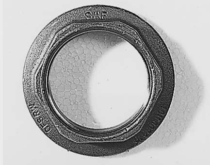
7 B) Maintenance instructions SK 1000 Disc / ET 120 SK RB 9019 W - SK 1000 ET 120 Hub unit Hub unit maintenance-free. Inspect for signs of wear at each brake disc change (e.g. escape of grease). After brake relining, observe the following points: Inspect the seals on the brake calliper. Never use high-pressure cleaners or cleaning fluids on the brake disc or wheel hub. Clean stub axle of any old grease and apply fresh SAF fitting paste. Lubricant specifications: Grease for repairs is contained in every repair kit. Stub axle: SAF Part No SAF fitting paste Tightening the hub nut On LH side as seen in direction of travel LH thread On RH side as seen in direction of travel RH thread Tightening torque 900 Nm. Each hub unit must be rotated smoothly at least twice while tightening the bolts. Hub nuts with LH thread are marked: Groove on the face. NOTE! Failure to observe these instructions may result in an accident risk! Worn brake linings or excessively worn brake discs result in a reduction in the braking efficiency or in a complete failure of the brake system. Brake type Thickness of brake disc A Wear limit of brake disc B Thickness of linings C Lining wear E Disc diameter in mm No. of brake pads per axle SBW Item No. Tightening torque (Nm) Spanner size (W.A.F.) Hexagon outside inside Wheel flange mounting 44 M18 x 1.5 x 75 or X 44 56/ TORX screw with head M18 x 1.5 x 75 or 65 Tightening process: pretighten to 50 Nm diagonally, turning angle of 90º diagonally tightened (1 1/2 nut corners) Caution! Bolts must not be oiled! External torx E24 Guide bearing on brake calliper 2 hex. socket head screws M16 x ,9 340 ±20 14 X Diaphragm/combination cylinder 2 hex. nuts X M16 x 1.5 Brake calliper mounting on axle body X M16 x 1.5 x 55 Fixing screws of the lining fixing hoop 30 ±15 17 X Assembly tools SAF Part No. Hub nut wrench Puller for Hub Unit Tool box compl /4 spanner external torx shape
8 B) Maintenance instructions Brake testing Fault-finding procedure Disc brake Lift vehicle, turn wheel by hand Does wheel turn freely? NO YES Residual pressure in brake cylinder? Running clearence OK? (see page 19) NO YES NO YES Running clearence OK? (see page 19) NO YES Check upline brake devices and replace, if necessary END Check adjuster (see page 9) END Uneven brake pad wear? 1) NO END YES Adjuster OK? (see page 9) NO YES Check brake calliper bearings and repair, if necessary (see page 18) END Brake calliper guide system OK? (see page 18) NO YES Replace brake calliper (see page 26) END Binding not due to disc brake END Check brake calliper bearings and repair, if necessary (see page 18) END 1) Difference between wear of inboard and outboard pad, and diagonal wear 2 mm. 8
 When the adjuster is functioning correctly the SAF ratchet wrench (arrow) must turn anti-clockwise.")

9 B) Maintenance instructions Adjuster check Remove cap. Caution! Do not overload or damage the hexagon drive (8 mm) of the adjuster. Do not use an open-ended spanner. Turn the adjuster approx. spanner turn clockwise using the SAF ratchet wrench. Actuate the brakes 5 times (approx. 1 bar) When the adjuster is functioning correctly the SAF ratchet wrench (arrow) must turn anti-clockwise. Caution! Ensure that there is sufficient room for the SAF ratchet wrench to rotate freely during adjustment. Note: As the number of rotation steps of the ring spanner increases, the turn angle or movement of the SAF ratchet wrench becomes smaller. If the SAF ratchet wrench rotates as described above, the adjuster is functioning correctly. If the following faults occur: The adjuster or SAF ratchet wrench a) does not turn, b) turns only with the first application of the brakes, c) turns forward and then back again at each application of the brakes, the adjuster is not functioning correctly and the brake calliper has to be replaced. Remove the SAF ratchet wrench (arrow). Coat the cap with grease in the snap-fit area, then push on the cap and ensure that it is fitting tightly. 9

10 B) Maintenance instructions Brake pad check Caution! Observe the wear limits of the brake pads. A B Check the thickness of the brake pads for compliance with the legal requirements at regular intervals, but at least every three months, depending on the operation of the vehicle. A = Minimum residual lining thickness 2 mm B = Total lining thickness of new pads 21 mm When the residual lining thickness is A 2 mm, replace the brake pads. Signs of wear Wear on the middle of the lining can be measured with a tape measure or a ruler either at the shoulder bolt (long bolt near the disc run in) or at the play bolt (short bolt near the disc run in). Here, the distance between the axle flange and the edge of the housing of each bolt is measured (see illustration). The amount of wear is determined to have been reached or exceeded by the following criteria: Short bolt: wear > 70 mm - replace linings Long bolt: wear > 97 mm - replace linings 10
11 B) Maintenance instructions Special notes Storage instructions During storage outdoors, ensure that moisture cannot enter the inside of the brake calliper through the brake cylinder connection. Painting instructions During painting work, all rubber parts must be covered as otherwise the rubber will become brittle and thus be damaged. Only brake cylinders approved by the brake or axle manufacturer may by used 11
12 C) Spare part illustrations SK 1000 Disc / ET 120 SK RB 9019 W - SK 1000 ET 120 Torque wrench settings Use a torque wrench. The use of impact wrenches is not accepted. Wheel nuts: Spigot-hub-centred fixing: M 22 x 1.5 / 600 Nm U-bolts: (diagonally in three stages ) M 22 / 650 Nm Shock absorber: M 24 / 400 Nm 12
13 C) Spare part designation SK 1000 Disc / ET 120 SK RB 9019 W - SK 1000 ET 120 Item Parts designation Item Parts designation 01 Axle beam assembly 22 Axle nut, RH, W.A.F Axle nut, LH, W.A.F Axle end assembly including items 27-31, 34, 39-40, 44, Hub Unit 29 Brake disc 30 Wheel bolt assembly including items 31, Wheel bolt 34 Wheel nut with pressure plate 39 Wheel flange 40 Hub cap with gasket 44 Torx screw 59/60 Brake calliper group including items 61, 65, 66, 70, Lining fixing hoop including items 63.1, Lining set 64.1 Brake linings 64.2 Lining retainer springs 070 Guide pin group including items , 80, ABS sensor 080 Guide pin group (folding bellows) including items 80, , Hexagon head bolt 56.1 Shoulder bolt Repair kits for SAF disc brakes SBW 1937 The following repair kits are available: Designation Content (Item No.) AT brake calliper, RH incl. Pads AT brake calliper, LH incl. Pads AT brake calliper, RH without Pads AT brake calliper, LH without Pads Brake calliper carrier with guide kit, RH 61, 70, 80 Brake calliper carrier with guide kit, LH 62, 70, 80 Guide pin group (folding bellows) 80 Guide pin group 70 Tappet with boot 66.1, 66.2 Brake pad retainer (per axle) 064 Cap for clearance adjuster (4 caps) 65 All kits available only as complete sets! When ordering spare parts quote correct axle identification serial no., refer to the axle type plate. 13


14 D) Installation instructions Repairing the brakes Remove the brake calliper. Park the vehicle on level, solid ground and chock the wheels to prevent the vehicle from rolling away. Lift the axle using a jack. Loosen the wheel nuts and remove the wheel. Remove the cap. Return adjuster clockwise turn until the stop. Loosen and remove the fixing screws of the lining retainer hoop. Move the brake calliper towards the rim and remove linings Move brake calliper towards the inside, remove linings and pressure plate. Unbolt the spring pressure or diaphragm cylinder from the brake calliper. Then loosen bolts (6 bolts M 16 x 1.5) and remove the brake calliper. 14


 Press the brake disc off the hub unit with 3 hexagon head bolts M 12 x 30.")
15 D) Installation instructions Check the brake calliper for free and easy movement. Back off the tappets on the adjuster until the boots are visible. Perform a visual inspection of the boots and all seals. Screw in the tappets again completely. Replacing the brake disc Unscrew bolts M 18 x 1.5 from the wheel flange and remove the wheel flange. Note: Bolts must not be oiled! (Observe tightening torques) Press the brake disc off the hub unit with 3 hexagon head bolts M 12 x 30. Clean contact surfaces before assembly. Caution! Seal on axle nut must not be damaged as this would invalidate all warranty claims. 15
 running towards the middle of the hub are permissible.")

16 D) Installation instructions Brake disc Brake disc diameter Permissible wear, see table in chapter Maintenance instructions. The brake disc may only be cleaned using a dry cleaning agent. A1 D1 B1 C1 Inspecting the brake disc Inspect the braking surface of the brake disc carefully for serviceability. A 1 Network-like cracks are permissible. B 1 Cracks up to max. 1.5 mm (width and depth) running towards the middle of the hub are permissible. C 1 Unevenness in the disc surface up to 1.5 mm is permissible. D 1 Cracks going right through the disc are not permissible. Check the brake disc thickness and turn down, if necessary. For safety reasons, the minimum thickness for turning down the brake discs is mm. Permissible wear, see table in chapter Maintenance instructions. Note: The compact wheel bearing unit and the brake calliper are not removed for turning down the brake disc. Replacing the hub unit Loosen axle nut and unscrew from stub shaft. Axle nut wrench, SAF Part No Note: Axle nut W.A.F. 85 on left-hand side as seen in direction of forward travel = left-hand thread. The axle nut with left-hand thread has a milled groove on the outer face for identification. The complete hub unit can be pulled off the stub shaft using a puller, SAF Part No (The hub unit cannot be overhauled and has to be replaced complete with the bolts of the wheel flange). 16
. Coat the hub unit bearing surfaces with SAF fitting paste and push onto the stub shaft. Tighten the axle nut to the prescribed torque.")


17 D) Installation instructions Installing the hub unit Emery the seating surfaces of the hub unit on the stub shaft down to the bare metal and coat with SAF fitting paste (SAF Part No ). Coat the hub unit bearing surfaces with SAF fitting paste and push onto the stub shaft. Tighten the axle nut to the prescribed torque. On LH side as seen in direction of travel LH thread On RH side as seen in direction of travel RH thread Tightening torque 900 Nm. Each hub unit must be rotated smoothly at least twice while tightening the bolts. Hub nuts with LH thread are marked: Groove on the face Axle nut W.A.F. 85: On left-hand side of vehicle (as seen in direction of forward travel) left-hand thread. Identification of axle nut with left-hand thread: Milled groove on outside of hexagonal head. Groove on the face. Tighten the axle nut. Axle nut wrench: SAF Part No Tightening torque 900 Nm. Each hub unit must be rotated smoothly at least twice while tightening the bolts. Special locking of the axle nut is not necessary. Place the wheel flange onto the hub unit and tighten the new, unoiled bolts to the prescribed torque. 17
 all around with copper paste and install in the sensor holder. Push in the ABS sensor until it contacts the exciter.")


18 D) Installation instructions Bolting on the brake calliper Position the brake calliper and screw in M 16 x 1.5 x 55 collared bolts (tightening torque 290 Nm). Coat ABS sensor (see arrow) all around with copper paste and install in the sensor holder. Push in the ABS sensor until it contacts the exciter. Measure the output voltage at the ABS sensor cable using a voltmeter (approx. 100 mv) while turning the brake disc or wheel flange. 80, Checking the folding bellows on the pressure pad Checking the protection cap and the moveability of the brake calliper: Move the brake calliper in the direction of the cylinder and check the protection cap 80, 66 the guide pin 70.1/80.2 and the adjustment screw forwear or damage. If necessary replace the protection cap (page 22)! 80, 70.1 Note! Should the protection cap 66 become defect, check to make sure no dirt or water has entered the inside of the brake or that the seal seating has not been damaged by corrosion. In case of doubt the brake should be replaced. If the protection cap 66 becomes damaged during service this must also be replaced (see page 22). Manually move the brake calliper on the guide pin over the whole length of travel and check for ease of movement. If movement is difficult replace both the bushes and the protection cap. Note! Do not squash the guide pin's protection cap against the brake mounting. 18


19 D) Installation instructions Adjustment screw Pressure plate Move the brake calliper so far so that there is enough distance between the brake disc on the actuation side to insert the brake lining. Insert the pressure plate into the brake mounting and push it against the adjustment screw. Note! The pressure plate must seat correctly in the brake mounting guide and the pin of the adjustment screw must be seated in the groove of the pressure plate, otherwise the correct functioning of the adjustment mechanism is endangered! Provision is made so that the adjustment screw can be turned until the pin sits correctly in the pressure plate groove. The protection cap must not be rotated during this action Inserting new brake linings 64.1 on the actuation pad. Move the brake calliper in the direction of the rim until the actuation side of the brake lining 64.1 sits on the brake disc Inserting new brake linings 64.1 on the rim side. With the help of a 1 mm thick feeler gauge (arrow) inserted between the rim side of the lining and the brake calliper, regulate the adjuster with a SAF ratchet wrench until both brake linings sit on the brake disc. Attention! Do not use excessive force on the corners of the adjuster. Note! Direction of rotation in regulating the adjuster is anti-clockwise. Do not assemble the lining retainer hoop until play has been adjusted /64.1 Setting new retainer springs 64.2 onto the brake linings 64.1 and pressure plate. Push and depress the lining retainer hoop 63.1 in the opening of the brake calliper so that the radial lugs of the retainer spring seat in the hoop. 19


20 D) Installation instructions Affixing new hex. screw 63.2 with 30±15 using a spanner onto the brake calliper Push the new plug 65 into the opening of the brake calliper! Check the wheel hub for freedom of movement. Note! Check the brakes on a rolling road test station after completion of work. 65 Fit the wheels. Tighten the wheel nuts using a torque wrench. Caution! Tighten the wheel nuts using a torque wrench again after driving 50 km and 150 km! 20

 and screw out approx. 30 mm anti-clockwise using a ring spanner on the hexagonals. During this time check the thread for damage or corrosion. 66 Note!")
21 D) Installation instructions Replacing the folding bellows of the pressure pad! Dismantle brake linings and pressure plate (see page 14) Move brake calliper by hand towards the cylinder. Pull out the protection cap 66 using a screwdriver from the brake calliper seating. Check the thread on the adjuster screw. Note! Lay the rim side brake lining in the lining cavity so that the adjuster cannot be screwed out of adjustment. After checking remove the linings again. Secure the adjuster screw against turning (arrow) and screw out approx. 30 mm anti-clockwise using a ring spanner on the hexagonals. During this time check the thread for damage or corrosion. 66 Note! The protection cap 66 can be replaced if dirt or water is seen to be present over the seal seat of the brake calliper, or if the protection cap has been damaged immediately prior to servicing. Should parts be found to be corroded then the brake should be replaced in case of doubt. After checking, grease the thread and partly screw the adjuster clockwise again. 21
 (illustration without adjustment screw) 66 Push the new protection cap 66 over the adjuster.")


22 D) Installation instructions 66 Clean the seating of the protection cap 66 in the brake calliper (arrow) (illustration without adjustment screw) 66 Push the new protection cap 66 over the adjuster. Centralize the press-in tool over the protection cap 66 and insert the protection cap in its seat in the brake calliper 59. (illustration without adjustment screw) Adjustment screw 66 Insert the protection cap 66 into the adjustment screw seating. Grease the rim lip before insertion. Note! Ensure an even and unwrinkled seating of the protection cap's rim lip in the groove of the adjustment screw. 22


23 D) Installation instructions 83, F F 83, Repairing the brake calliper bearing with guide and seal kit Dismantle the brake calliper 59 from the brake mounting 61 and additionally remove the cap 83 of the guide pin 70.1/80.2 with a screwdriver from the housing Note! Do not damage the holes for the cap in the housing Loosen the screws 70.6/80.1 with a spanner. Remove the brake calliper 59 from the brake mounting Note! Danger of trapping through loose brake calliper! Clean contact surface (flush) on the brake mounting 61 to the guide pin. 59 Remove the guide pin 70.1/80.2 from the brake calliper 59, remove the protection cap 80 from the groove. 70.1/ Lay the brake calliper 59 on a firm surface so that the cover opening of the brake calliper is uppermost in order to press out the bushes 70.3/ / /

 the inner bush with mandrel (L 1 = 52.2 ± 0.")
, in both cases press in until they meet the stop.")
 with mandrel (L 3 = 38.7 ± 0.")
 of the brake calliper (59). Note!")
24 D) Installation instructions F Press out the bushes 70.3/80.3 from the brake calliper using a press and mandrel. Clean the holes in the brake calliper. 70.3/ / F L 1 L 2 A B F. Press in two new bushes 70.3 and for the longer guide pin 70.1: Firstly (A) the inner bush with mandrel (L 1 = 52.2 ± 0.2 mm), and finally (B) the outer bush with a mandrel (L 2 = 13.2 ± 0.2 mm), in both cases press in until they meet the stop. Grease sliding surfaces of the bushes and the space between them. F Press in a new bush 80.3 for the shorter guide pin Press in bush (C) with mandrel (L 3 = 38.7 ± 0.2 mm) until it meets the stop. Grease sliding surfaces of the bush. L 3 C Insert the new protection cap 80 in the seat (arrow) of the brake calliper (59). Note! Clean seating before insertion. For ease of insertion of the protection cap it is recommended to lightly grease the rim lip. Note! Ensure an even and unwrinkled seating of the protection cap's rim lip in the groove of the brake calliper. 24


25 D) Installation instructions 70.1/80.2 Grease the running surfaces for the guide pins 70.1/80.2 and the rim lip of the protection cap 80. Insert the new guide pins from the direction of the cylinder into the brake calliper 59 and push the protection cap 80 against the seating of the guide pins 70.1/80.2. Lightly move the guide pins backwards and forwards several times as illustrated in the sketch. The longer guide pin 70.1 is the shoulder bolt and is fitted on the brake disc run in side. The shorter guide pin 80.2 is the play bolt and is fitted on the brake disc run out side. Remove excessive grease. The flat surfaces of the guide pins to the brake mounting (arrow) must be free of grease! Seat the brake calliper 59 onto the brake mounting 61 and insert the fitted guide pins 70.1/80.2 flush. Fit the new screws 70.6 (long for the shoulder bolt 70.1), 80.1 (short for the play bolt 80.2) through the previously fitted guide pins in the brake calliper 59 and screw the brake calliper to the brake mounting 61. Tightening sequence: 1st screw 70.6 / 2nd screw 80.1 Note! It must be ensured during tightening of the screws when assembling that the protection cap 80 is not damaged or rotated. First, screw tightly the slide fit longer guide pin 70.1 and then screw tightly the running fit shorter guide pin Should the guide pins 70.1/80.2 be loosened during maintenance work from the brake mounting 61, then these must be replaced with new screws 70.6/80.1 when re-assembling Move the brake calliper several times backwards and forwards over the guide pins 70.1/80.2. Ensure ease of movement. Note! Do not squash the guide pins against the brake mounting! 70.1 F F Grease the holes for the cover plate 83 in the brake calliper 59. Insert the new cover plate 83 into the holes of the brake calliper 59 and press home using a suitable tool. Note! Avoid damaging the cover
.")
.")
26 D) Installation instructions Fitting the brake calliper Seat the brakes with brake mounting over the brake disc and fit to the axle. Tightening sequence of the screws: Right hand side clockwise Left hand side anti-clockwise Each time begin the sequence with the shoulder bolt (if applicable). Position of shoulder bolt: In the direction of wheel rotation - the run out side of the outer corner of the flange. Replacing the brake cylinder Before fitting the brake cylinder clean the sealing surface of the brake calliper and grease the bearing on the brake lever (arrow). Set the brake cylinder onto the brake calliper and screw the nuts tightly with a spanner. Note! According to the respective fitting position, the lower drain holes on the bottom of the cylinder must be clear. 26


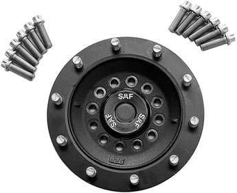


27 D) Installation instructions Overview of Hub Unit components Hub Unit Hub Unit Hub cap Axle nut, RH / LH thread Wheel flange Brake disc Brake calliper 27


28 E) Service tools 1. Axle nut wrench WAF 85 SAF Part No Wheel hub puller SAF Part No WABCO tool box SAF Part No SAF ratchet wrench SAF Part No
29 F) Bolt / Nut torque values The following tightening torques are only valid if no other values are given in the axle maintenance chart. Torque wrenches settings, impact wrench not permissible. Thread W.A.F. Material 8,8 10,9 12,9 M 8 W.A.F M 8 x M 10 W.A.F. 17 / M 10 x M 12 W.A.F. 19 / M 12 x M 14 W.A.F. 22 / M 14 x M 16 W.A.F M 16 x M 18 W.A.F M 18 x M 20 W.A.F M 20 x M 22 W.A.F M 22 x M 24 W.A.F M 24 x M 27 W.A.F M 27 x M 30 W.A.F M 30 x M 36 x 2 W.A.F Wheel fixing: Wheels see appropriate axle maintenance chart. TRILEX wheels M Nm M Nm 29
30 Soforthilfe im Pannenfall NonStopService 24 Support in the case of service SV11199GB Edition 01/2006 Last updated Amendments and errors reserved SAF Im Servicefall wählen Sie bitte immer die Rufnummer Ihres Heimatlandes. In the case of service please always dial the number of your own country. Inland home country / Otto Sauer Achsenfabrik GmbH Hauptstraße 26 D Bessenbach Tel +49 (0) / Fax +49 (0) / A B BG BIH CH CZ D DK E EST F FIN FL GB GR H HR I IRL L LT LV MC MK N NL P PL RO RSM S SK SLO TR YU Vom Ausland from abroad /
Maintenance and Repair Manual for SAF Disc Brakes SK RB 9022 K/SK RB 9019 K with KNORR brake calliper SK 1000 ET 120
 Maintenance and Repair Manual for SAF Disc Brakes SK RB 9022 K/SK RB 9019 K with KNORR brake calliper SK 1000 ET 120 Edition 01/2006 Service Vehicle information Manufacturer... Address... Body type...
Maintenance and Repair Manual for SAF Disc Brakes SK RS 9022 K SK 1000 ET 0
 Maintenance and Repair Manual for SAF Disc Brakes SK RS 9022 K SK 1000 ET 0 Edition 01/2006 Service Vehicle information Manufacturer... Address... Body type... Chassis no... Year of manufacture... Registration
Maintenance and Repair Manual SK RS SK 1000 ET 0
 Maintenance and Repair Manual SK RS 9042 - SK 1000 ET 0 Edition 01/2006 Service Vehicle information Manufacturer... Address... Body type... Chassis no... Year of manufacture... Registration, date-in-service...
RB/RLB INTEGRAL TEILE ARTS VICE
 Conversion Hub Unit SK RB/RLB to Hub Unit SK RB/RLB INTEGRAL SAF SERVICE und ORIGINALTEILE SAF SERVICE and ORIGINAL PARTS www.saf-axles.com Edition 06/2006 Service Vehicle and axle identification Trailer
Maintenance and Repair Manual SK RS SK 500 plus
 Maintenance and Repair Manual SK RS 9042 - SK 500 plus Edition 01/2006 Service Vehicle information Manufacturer... Address... Body type... Chassis no... Year of manufacture... Registration, date-in-service...
Maintenance and Repair Manual Axle types SK RS / RZ 9042 SK RS / RZ SK RS / RZ 9037 SK RS / RZ 11037
 Maintenance and Repair Manual Axle types SK RS / RZ 9042 SK RS / RZ 11242 SK RS / RZ 9037 SK RS / RZ 11037 Edition 02/02/2006 Service Vehicle information Manufacturer... Address... Body type... Chassis
disc brake axle with WABCO calipers
 1 2 disc brake axle with WABCO calipers 3 4 disc brake axle with WABCO calipers 5 6 disc brake axle with WABCO calipers IMT axles are supplied as non-cambered and are within the limits of a 2 minute negative
Mechanical Sliding Caliper Disc Brake. Type PAN 19-1 Assembly and Maintenance Instructions
 WABCO Mannheim Mechanical Sliding Caliper Disc Brake Type PAN 19-1 Assembly and Maintenance Instructions WABCO Radbremsen GmbH Postfach 71 02 63 D-68222 Mannheim Bärlochweg 25 D-68229 Mannheim +49 (0)6
Quick Reference Guide: Technical Data SAF-axles with air suspension system. IMS Limited
 Quick Reference Guide: Technical Data SAF-axles with air suspension system IMS Limited IMS Limited is a key distributor for a range of premium products aimed at the commercial vehicle market and is the
General Operating and Service Manual
 General Operating and Service Manual Air suspension systems and axles with drum brakes Edition 0/2007 Air suspension system, Type INTRA Vehicle and axle identification The axle type designation (Version),
Service Bulletin No. 1066
 QUALITIES THAT MAKE THE DIFFERENCE Service Bulletin No. 1066 COACH MODEL BULLETIN TYPE : T2100 Series ; C2000 Series : Service information MANUAL & SECTION : Maintenance Manual : Chapter 5 - Brakes Spare
PAN 17 MECHANICAL SLIDING CALLIPER DISC BRAKE ASSEMBLY AND MAINTENANCE INSTRUCTIONS
 PAN 17 MECHANICAL SLIDING CALLIPER DISC BRAKE ASSEMBLY AND MAINTENANCE INSTRUCTIONS PAN 17 MECHANICAL SLIDING CALLIPER DISC BRAKE Assembly and Maintenance Instructions 2nd edition This publication is
MAXXUS 22. Mechanical Sliding Disc Brake Caliper
 MAXXUS 22 Mechanical Sliding Disc Brake Caliper MAXXUS 22 Mechanical Sliding Disc Brake Caliper Assembly Instructions/ Maintenance Guidelines Edition 1 This publication is not subject to any update service.
Service Manual RA-SB0002-EN. Pneumatic Disc Brake. SB6.../SB7... Axial and Radial Disc Brake KNORR-BREMSE. Systeme für Nutzfahrzeuge
 Service Manual RA-SB0002-EN Pneumatic Disc Brake SB6.../SB7... Axial and Radial Disc Brake KNORR-BREMSE Systeme für Nutzfahrzeuge Index Page 1 Overview 1.1 Axial Disc Brake Components... 4 1.2 Axial Disc
WAP disc brake technology. Assembly, operating and maintenance instructions
 WAP disc brake technology Assembly, operating and maintenance instructions Number MA-025 Date 22.07.2010 1 Please read this operating and service manual before starting the vehicle. It forms part of the
MAXX TM 22T MECHANICAL SLIDING CALIPER DISC BRAKE INSTALLATION AND MAINTENANCE INSTRUCTIONS
 MAXX TM 22T MECHANICAL SLIDING CALIPER DISC BRAKE INSTALLATION AND MAINTENANCE INSTRUCTIONS MAXX TM 22T Mechanical Sliding Caliper Disc Brake Installation and Maintenance Instructions Edition 1 This publication
Maintenance instructions. BPW Trailer Axles and Suspensions. BPW-W e
 Maintenance instructions BPW Trailer Axles and Suspensions BPW-W 33111701e Page 2 BPW-W 33111701e BPW-W 33111701e Page 3 Contents Important information 1 1. Important information... Page 3 1.1 General
BPW Trailer Axles and Suspensions
 BPW BERGISCHE ACHSEN Maintenance instructions BPW Trailer Axles and Suspensions MAINTENANCE INSTRUCTIONS . IMPORTANT INFORMATION CONTENTS: Page. IMPORTANT INFORMATION.. General.. Maintenance, repair and
3 Axles and brakes. 3.1 Function and construction of the axles Construction Function
 3 Axles and brakes 3.1 Function and construction of the axles 3.1.1 Function Each wheel has an independent suspension system in the axle body (1), so that individual wheel suspension is provided. The swinging
Maintenance instructions. BPW Trailer Axles and Suspensions. BPW-W e
 Maintenance instructions BPW Trailer Axles and Suspensions BPW-W 33111401e Page 2 BPW-W 33111401e BPW-W 33111401e Page 3 Contents Important information 1 1. Important information... Page 3 1.1 General
Maintenance instructions. BPW Trailer Axles and Suspensions. BPW-W e
 Maintenance instructions BPW Trailer Axles and Suspensions BPW-W 33111401e Page 2 BPW-W 33111401e BPW-W 33111401e Page 3 Contents Important information 1 1. Important information... Page 3 1.1 General
Maintenance instructions. BPW Trailer Axles and Suspensions. BPW-W e
 Maintenance instructions BPW Trailer Axles and Suspensions BPW-W 33111501e Page 2 BPW-W 33111501e Contents 1. Important information... Page 3 1.1 General Page 3 1.2. Maintenance, repair and spare parts
General Operating and Service Manual SAF suspension systems and J-Series-axles with drum brakes
 General Operating and Service Manual SAF suspension systems and J-Series-axles with drum brakes SAF SERVICE und ORIGINALTEILE SAF SERVICE and ORIGINAL PARTS www.saf-axles.com Edition 01/2006 Service Vehicle
ORIGA SYSTEM PLUS Guides, Brakes and Valves for Modular Linear Drive Systems OSP Appendix to the Operating Instructions
 ORIGA SYSTEM PLUS Guides, Brakes and Valves for Modular Linear Drive Systems OSP Appendix to the Operating Instructions TAll personnel who have anything to do with the OSP fitted with guides, brakes or
UNITIZED WHEEL BEARING HUB
 UNITIZED WHEEL BEARING HUB The FKH unitized wheel bearing hub is fitted with an SKF cartridge bearing unit. This bearing cartridge is sealed and is not serviceable (adjustable or grease able). While the
Sisu S-Cam Drum Brakes
 Sisu S-Cam Drum Brakes (For hub reduction rear axles since 1992) Maintenance Manual Sisu Axles, Inc. Autotehtaantie 1 P.O. Box 189 FIN-13101 Hämeenlinna Finland Phone int + 358 204 55 2999 Fax int + 358
W BW GW. Workshop manual. Mechanical suspensions BPW, series ECO Cargo W / BW / GW. BPW-WH-W-BW-GW e
 W BW GW Workshop manual Mechanical suspensions BPW, series ECO Cargo W / BW / GW BPW-WH-W-BW-GW 35251401e Page 2 BPW-WH-W-BW-GW 35251401e BPW-WH-W-BW-GW 35251401e Page 3 Contents 1. Product identification...
BRAKE SYSTEM Return To Main Table of Contents
 BRAKE SYSTEM Return To Main Table of Contents GENERAL... 2 BRAKE PEDAL... 10 MASTER CYLINDER... 13 BRAKE BOOSTER... 16 BRAKE LINE... 18 PROPORTIONING VALVE... 19 FRONT DISC BRAKE... 20 REAR DRUM BRAKE...
Maintenance and Repair Instructions TM 89/03
 TM 89/0 410 X 180 Simplex 410 X 180 Duplex 500 X 10 Simplex 500 X 160 Simplex 500 X 180 Duplex The brake described in this manual is subject to development and corresponds to the state-of-the-art at the
Operating manual. Air suspension systems and axles with disc brakes Valid for axle types B / BI / SI / ZI
 Operating manual Air suspsion systems and axles with disc brakes Valid for axle types B / BI / SI / ZI XL-AS11405OM--DE Translation of the original operating manual 1.1 Dear customer, This operating manual
SD AIR DISC BRAKE FIGURE 1 - BENDIX AIR DISC BRAKE SUPPLY PORT ACTUATOR ROD LEVER RETURN SPRINGS ECCENTRIC BEARING ACTUATING BEAM
 AIR DISC BRAKE SD-23-7550 SUPPLY PORT ACTUATOR ROD RETURN SPRINGS LEVER OUTER BRAKE PAD ACTUATING BEAM ECCENTRIC BEARING ROTOR INNER BRAKE PAD AXIAL RADIAL FIGURE 1 - BENDIX AIR DISC BRAKE 1 Index Page
REAR SUSPENSION GROUP CONTENTS GENERAL DESCRIPTION REAR SUSPENSION DIAGNOSIS LOWER ARM AND TOE CONTROL ARM ASSEMBLY...
 34-1 GROUP 34 CONTENTS GENERAL DESCRIPTION........... 34-2 DIAGNOSIS.... 34-2 INTRODUCTION....................... 34-2 TROUBLESHOOTING STRATEGY........ 34-2 SYMPTOM CHART..................... 34-3 SYMPTOM
Version VDL Weweler b.v. Maintenance & Installation Manual
 Version 1.3 18-8-2014 VDL Weweler b.v. Maintenance & Installation Manual CONTENTS 1. Introduction 2 2. Maintenance work 3 - Overview - Air springs - Shock absorbers - U-Bolts - Pivot Bolts - Air spring
Pneumatic Disc Brake SL7.../ SM7...
 C o m m e r c i a l V e h i c l e S y s t e m s S e r v i c e M a n u a l Pneumatic Disc Brake SL7.../ SM7... Service kits Service tools Description/Function Service instructions Overview of Tool Kits
Information I Manuals I service. AIR premium x2. Operating Instructions _a I 03/2012
 GB Information I Manuals I service AIR premium x2 Operating Instructions 1 568 419_a I 03/2012 1 6 7 2 3 4 8 5 Dear customer, Your vehicle is equipped with the AL KO AIR Premium X2 electronically controlled
ZE ZE ZE. Simplex expanding wedge brake Assembly and Maintenance Instructions
 Simplex expanding wedge brake Assembly and Maintenance Instructions Simplex expanding wedge brake Assembly and Maintenance Instructions Edition 1 This publication is not subject to any update service.
General operating and maintenance instructions Air suspension systems and axles with disc brakes
 Geral operating and maintance instructions Air suspsion systems and axles with disc brakes XL-SA40002MM--DE Rev A 03.2016 Translation of the original geral operating and maintance instructions Please note
REAR SUSPENSION GROUP CONTENTS GENERAL DESCRIPTION TRAILING ARM ASSEMBLY REAR SUSPENSION DIAGNOSIS
 34-1 GROUP 34 CONTENTS GENERAL DESCRIPTION......... 34-2 DIAGNOSIS.. 34-3 INTRODUCTION TO DIAGNOSIS........................ 34-3 DIAGNOSIS TROUBLESHOOTING STRATEGY...... 34-3 SYMPTOM CHART...................
ECO Plus - Warranty documents. Axle systems with air suspension
 ECO Plus - Warranty documents Axle systems with air suspension Valid for all complete ECO Plus air-suspended axle systems from production date 01.01.2017 BPW-GD-ECO Plus 39091704e Page 2 BPW-GD-ECO Plus
SUSPENSION AND AXLE SA 1 SUSPENSION AND AXLE
 SA1 SA2 Troubleshooting TROUBLESHOOTING Problem Possible cause Remedy Front Page Rear Wanders/pulls Tires worn or improperly inflated Wheel alignment incorrect Hub bearing worn Front or rear suspension
Parking brake Mechanical brake acting on rear wheels
 11 Brake System 11.1 General SPECIFICATIONS EJTC0010 Master cylinder Type Tandem type I.D. mm(in.) 20.64 mm (0.813 in.) Fluid level warning sensor Provided Brake booster Type Vacuum Boosting ratio 4.0
Rear axle, servicing (frontwheel-drive
 Page 1 of 26 42-1 Rear axle, servicing (frontwheel-drive vehicles) WARNING! Do not attempt to weld and/or straighten the axle beam. Do not re-use fasteners that are worn or deformed in normal use. Some
Webinar Series. APTA Bus Technical Maintenance Committee Webinar Series. Disc Brake Wheels On Inspection. Presents
 1 Webinar Series APTA Bus Technical Maintenance Committee Webinar Series Presents Disc Brake Wheels On Inspection January 28, 2015 2 Introduction Welcome to today s webinar in which we will cover a wheels
Removing and installing cylinder head
 31 30 29 28 27 26 25 24 23 22 1 2 3 11 12 10 4 9 5 6 7 8 Removing and installing cylinder head Checking compression pressure page 15-24. Notes: When installing a replacement cylinder head with a mounted
1 of 11 4/11/ :35 AM
 1 of 11 4/11/2015 11:35 AM Rear Disc Brake Pads Replacement Special Tools * KM-6007 Resetting Tool * KM-6007-30 Adaptor Removal Procedure 2 of 11 4/11/2015 11:35 AM Caution: Refer to Brake Dust Caution
How it s done Fitting instructions for replacing brakes
 How it s done Fitting instructions for replacing brakes Fitting instructions for replacing brakes We invest a lot in developing our products. We complete up to 300,000 test kilometres and 1,000 hours of
EAC. Workshop manual. BPW air suspensions, series ECO Air COMPACT. BPW-WH-EAC e
 EAC Workshop manual BPW air suspensions, series ECO Air COMPACT BPW-WH-EAC 35161701e Page 2 BPW-WH-EAC 35161701e Valid: 01.01.2017 Subject to change without notice. Current versions and additional information
Split Body Valves with Bellows Seal Series Globe Valves Series Angle Valves Series Way-Valves
 Installation, Operation, Maintenance Instructions Split Body Valves with Bellows Seal Series 025 300 Globe Valves Series 027 300 Angle Valves Series 028 300 3-Way-Valves 1 GENERAL INFORMATION These instructions
REAR AXLE AND SUSPENSION RA 1
 REAR AXLE AND SUSPENSION RA1 RA2 REAR AXLE AND SUSPENSION Troubleshooting TROUBLESHOOTING Problem Possible cause Remedy Page Wanders/pulls Tires worn or improperly inflated Replace tires or inflate to
OVERHAUL. Remove the union bolt and a gasket from the disc brake cylinder, then disconnect the flexible hose from the disc brake cylinder.
 OVERHAUL COMPONENTS: See page 3232 Overhaul the RH side by the same procedures with LH side. Two types of brake pad exist; one is with slit and the other without slit. 1. REMOVE REAR WHEEL 2. DRAIN FLUID
REAR DRIVE SHAFT (3S GTE ENGINE)
") SA52 REAR DRIVE SHAFT (3SGTE ENGINE) COMPONENTS SA53 NOTICE: The axle bearing could be damaged if it is subjected to the vehicle weight, such as when moving the vehicle with the drive shaft removed. Therefore,
SA52 REAR DRIVE SHAFT (3SGTE ENGINE) COMPONENTS SA53 NOTICE: The axle bearing could be damaged if it is subjected to the vehicle weight, such as when moving the vehicle with the drive shaft removed. Therefore,
MAINTENANCE & SERVICE BULLETIN KT AIR SUSPENSION. Note: For parts identification go to the FKH Parts View Bulletin KPS on
 KT AIR SUSPENSION KT 250 T KT 300 T KT 250 U KT 300 U Note: For parts identification go to the FKH Parts View Bulletin KPS-001-1112 on www.khitch.com.au Contents 1. Tightening Instruction 2. Pivot bolt
UNITIZED WHEEL BEARING HUB
 UNITIZED WHEEL BEARING HUB The FKH unitized wheel bearing hub is fitted with a cartridge bearing unit. This bearing cartridge is sealed and is not serviceable (adjustable or grease able). While the unitized
SCdefault. 900 Installation instructions
 SCdefault 900 Installation instructions SITdefault Sports chassis MONTERINGSANVISNING INSTALLATION INSTRUCTIONS MONTAGEANLEITUNG INSTRUCTIONS DE MONTAGE Accessories Part No. Group Date Instruction Part
BPW height-adjustable drawbars
 Maintenance instructions ZAV BPW BERGISCHE ACHSEN BPW height-adjustable drawbars Series ZAV REPAIR, MAINTENANCE AND OPERATING INSTRUCTIONS Maintenance and Operating Instructions ZAV Table of contents:
Service Manual PNEUMATIC DISC BRAKE SN6 - SN7 - SK7. Y (EN - Rev. 006) SEPTEMBER 2015
 SEPTEMBER 2015") Y006471 - (EN - Rev. 006) SEPTEMBER 2015 Service Manual PNEUMATIC DISC BRAKE SN6 - SN7 - SK7 CONTENT Service Kits Service Tools Description/Function Service Instructions Y006471 - (EN - Rev. 006) September
Y006471 - (EN - Rev. 006) SEPTEMBER 2015 Service Manual PNEUMATIC DISC BRAKE SN6 - SN7 - SK7 CONTENT Service Kits Service Tools Description/Function Service Instructions Y006471 - (EN - Rev. 006) September
BRAKE SYSTEM Toyota Celica DESCRIPTION DRUM BRAKES ADJUSTMENTS BRAKE PEDAL HEIGHT ADJUSTMENTS BRAKE PEDAL FREE PLAY ADJUSTMENTS
 BRAKE SYSTEM 1988 Toyota Celica 1988-89 BRAKES Toyota Celica, Corolla, MR2, Tercel DESCRIPTION The hydraulic brake system uses a tandem master cylinder with a vacuum power assist servo. MR2 and some Celica
H K N. Workshop manual. BPW trailer axles with drum brakes. BPW-WH-HKN e
 H K N Workshop manual BPW trailer axles with drum brakes BPW-WH-HKN 35191601e Page 2 BPW-WH-HKN 35191601e BPW trailer axles with drum brake S-camshaft SN 420 / SN 360 / SN 300 ECO Plus 3, ECO Plus 2, ECO
Webinar Series APTA Standards Quarterly Webinar Series
 1 Webinar Series APTA Standards Quarterly Webinar Series Presented by APTA Brake and Chassis Working Group Disc Brake Wheels On Inspection January 26, 2017 2 Moderator Presenter Jerry Guaracino Assistant
Standard Valves Series Globe Valves Series Angle Valves Series Way-Valves
 Installation, Operation, Maintenance Instructions Standard Valves Series 035 000 Globe Valves Series 031 000 Angle Valves Series 033 000 3-Way-Valves 1 GENERAL INFORMATION These instructions are designed
CHASSIS CONTENTS FRONT WHEEL 6-1 FRONT BRAKE 6-6 FRONT FORK 6-14 STEERING STEM 6-20 REAR WHEEL AND REAR BRAKE 6-25 SUSPENSION 6-31 REAR SWING ARM 6-36
 CHASSIS CONTENTS FRONT WHEEL 6-1 FRONT BRAKE 6-6 FRONT FORK 6-14 STEERING STEM 6-20 REAR WHEEL AND REAR BRAKE 6-25 SUSPENSION 6-31 REAR SWING ARM 6-36 6 6-1 CHASSIS FRONT WHEEL REMOVAL Support the machine
FAG Wheel Bearing Repair Solution for Light Commercial Vehicles
 FAG Wheel Bearing Repair Solution for Light Commercial Vehicles Mercedes-Benz Sprinter, Viano, Vito and Volkswagen Crafter Front Axle The content of this brochure shall not be legally binding and is for
2006 MINI Cooper SUSPENSION Wheels & Tires - Repair Instructions - Cooper (1.6L) R50/W10 & Cooper S
 R50/W10 & Cooper S") WHEELS 2002-05 SUSPENSION Wheels & Tires - Repair Instructions - Cooper (1.6L) R50/W10 & Cooper S 36 10 300 REMOVING OR INSTALLING FRONT OR REAR WHEEL NOTE: For Special Tool identification, see WHEEL AND
WHEELS 2002-05 SUSPENSION Wheels & Tires - Repair Instructions - Cooper (1.6L) R50/W10 & Cooper S 36 10 300 REMOVING OR INSTALLING FRONT OR REAR WHEEL NOTE: For Special Tool identification, see WHEEL AND
FRONT AXLE AND SUSPENSION FA 1
 FRONT AXLE AND SUSPENSION FA1 FRONT AXLE AND SUSPENSION FA2 FRONT AXLE AND SUSPENSION Troubleshooting TROUBLESHOOTING Problem Possible cause Remedy Page Wanders/pulls Tires worn or improperly inflated
Technical Description Edition 2007 Mounting, maintenance and repair of propshafts with flanged universal joints
 Technical Description Edition 2007 Mounting, maintenance and repair of propshafts with flanged universal joints 1. Recommendations Assembly, disassembly, maintenance and repair of propshafts should be
SERVICE BULLETIN No. 1088
 SERVICE BULLETIN No. 1088 Circulate to listed addressees COACH MODEL BULLETIN TYPE MANUAL & SECTION : T800 Series; T900 Series; T 2100 Series; C2045 : Service Information : Maintenance Manual: Chapter
MAN Engines & Components. MAN Warranty Process
 MAN Engines & Components MAN Warranty Process MAN ENGINES & COMPONENTS MAN - MEC Warranty Process June 2015 MAN Engines & Components Warranty process between New Flyer and MAN The warranty validation process
1. introduction 3 2. Wheel bearing special features 4 3. Wheel bearing units from an economical point of view 5
 Motor chassis Service Technical BROCHuRE Wheel Bearing Repair Solutions for Light Commercial Vehicles CONTENT 1. introduction 3 2. Wheel bearing special features 4 3. Wheel bearing units from an economical
SECTION C: Wheel Hubs and Bearings Full Floating Axle Dana
 SECTION 205-02C: Wheel Hubs and Bearings Full Floating Axle Dana REMOVAL AND INSTALLATION 2007 F-53 Motorhome Chassis Workshop Manual Procedure revision date: 12/04/2006 Wheel Hub Material Item Premium
REAR AXLE Click on the applicable bookmark to selected the required model year
 REAR AXLE 27-1 REAR AXLE CONTENTS GENERAL INFORMATION.................. 2 SERVICE SPECIFICATIONS................. 3 LUBRICANTS.............................. 3 SEALANTS AND ADHESIVES.............. 4 SPECIAL
Installation and Operation Manual CBX/CB Series
 Installation and Operation Manual CBX/CB Series Fixed Frame Top Mount Trailer Air Suspension For Disc and Drum Brake Applications XL-AS11406OM-en-US Rev C Contents Contents Page Introduction... 3 Warranty...
Guidelines for inspection and servicing. VBG MFC coupling 2018
 Guidelines for inspection and servicing VBG MFC coupling 208 General information General The components used to connect a vehicle and trailer are exposed, even during normal use, to very high tensions.
Servicing front brakes
 46-1 Servicing front brakes C54 brake caliper, servicing Special tools and workshop equipment required VAG 1331 Torque wrench (or equivalent) VAG 1410 Torque wrench (or equivalent) VAG 1869/2 Brake pedal
SERVICE MANUAL. Chairman. Playman/Robo
 SERVICE MANUAL Chairman Playman/Robo US How to contact Permobil Permobil Inc. USA 6961 Eastgate Blvd. Lebanon, TN 37090 USA Phone: 800-736-0925 Fax: 800-231-3256 Email: info@permobilusa.com Head Office
L Rev. 10/04. CSI Midland/Gunite Automatic Brake Adjuster Service Manual
 L30006 Rev. 10/04 CSI Midland/Gunite Automatic Brake Adjuster Service Manual TABLE OF CONTENTS Overview...3 Installation Procedures...4 Brake Adjustment...10 Installation Procedures...11 Brake Adjustment...13
FRP Ball Valves INSTALLATION & MAINTENANCE MANUAL
 FRP Ball Valves INSTALLATION & MAINTENANCE MANUAL FRP BALL VALVES TABLE OF CONTENTS MAINTENANCE AND INSTALLATION INSTRUCTIONS 1. 2. 2.1 2.2 2.3 2.4 GENERAL...Page 1 HANDLING...1 Receiving and Storing...1
Inspection and Verification, Ranger
 file://c:\tso\tsocache\vdtom_5368\svk~us~en~file=svk53a03.htm~gen~ref.htm Page 1 of 1 Section 05-03A: Wheel Hubs and Bearings, Front Wheels, 4- Wheel Drive DIAGNOSIS AND TESTING 1997 Ranger 4x4 with Dana
USER INSTRUCTIONS. Kämmer SmallFlow / / SP Low and Micro Flow Valves. Installation Operation Maintenance
 User Instructions SmallFlow - KMENIM5000-02 02/15 USER INSTRUCTIONS Kämmer SmallFlow - 385000 / 385300 / 385000 SP Low and Micro Flow Valves FCD KMENIM5000-02 02/15 Installation Operation Maintenance Experience
SECTION ZF FRONT AXLE
 04-101.01/ 1 2011JA14 SECTION 04-101.01 6 3 5 1 2 9 1. Upper radius rod 2. Lower radius rod 3. Caliper 4. BRAKE Disk 5. Pneumatic connector 6. Hub 7. steering knuckle 8. Grease Fitting 9. Pneumatic connector
Maintenance and Parts Manual ADZ Series Suspension
 Maintenance and Parts Manual ADZ Series Suspension XL-PS10452MM-en-US Rev C Contents Contents Page Introduction... 3 Warranty... 3 Notes, Cautions, and Warnings... 3 Section 1 General Safety Instructions...
12. FRONT WHEEL/FRONT BRAKE/
 12 4.5kgm 0.9kg-m 4.5kg-m 12-0 SERVICE INFORMATION... 12-1 HYDRAULIC BRAKE... 12-10 TROUBLESHOOTING... 12-2 FRONT SHOCK ABSORBER... 12-16 FRONT WHEEL... 12-3 STEERING HANDLEBAR... 12-19 FRONT BRAKE...
12. FRONT WHEEL/FRONT BRAKE/
 12 12 12-0 SERVICE INFORMATION... 12-1 FRONT BRAKE... 12-7 TROUBLESHOOTING... 12-2 FRONT SHOCK ABSORBER... 12-18 STEERING HANDLEBAR... 12-3 FRONT FORK... 12-21 FRONT WHEEL... 12-4 SERVICE INFORMATION GENERAL
WARRANTY GUIDELINES IMS
 WARRANTY GUIDELINES CONTENTS The following are presented in page order below to assist you with your warranty/guarantee claims. Page 2 Page 3 Page 4 Page 5 Page 6 Page 7 Page 8 Page 9 Page 10 Page 11 Page
Service Manual for Drum Brake Axles Tapered and Parallel Spindle Axles
 Service Manual for Drum Brake Axles Tapered and Parallel Spindle Axles XL-TA10006OM-en-US Rev C Contents Contents Page Introduction... 3 Warranty... 3 Notes, Cautions, and Warnings... 3 Section 1 General
SACHS Clutches The Intelligent Choice for the Long Haul
 SACHS Clutches The Intelligent Choice for the Long Haul Twin XTend Clutch Installation Objectives: Identification Operation Tools Installation Troubleshooting Identification 15.5 Self Adjusting Clutch
BRAKE SYSTEM Nissan 240SX DESCRIPTION BRAKE BLEEDING * PLEASE READ FIRST * BLEEDING PROCEDURES ADJUSTMENTS BRAKE PEDAL HEIGHT SPECS TABLE
 BRAKE SYSTEM 1990 Nissan 240SX 1990 BRAKE SYSTEMS Nissan Disc & Drum Axxess, Maxima, Pathfinder, Pickup, Pulsar NX, Sentra, Stanza, 240SX, 300ZX DESCRIPTION All brake systems are hydraulically operated
Installation Instructions
 Preparing your vehicle to install your brake system upgrade 1. Rack the vehicle. 2. If you don t have a rack, then you must take extra safety precautions. 3. Choose a firmly packed and level ground to
TMC LMV & LMXp series
 TMC LMV & LMXp series AIR SUSPENSION SERVICE MANUAL TMC Australia Pty Ltd Telephone: + 61 3 8786 3688 78 Star Crescent Facsimile: + 61 3 8786 3699 Hallam E-Mail: info@tmcaus.com.au Victoria 3803 Australia
Installation Instructions for disc brakes
 Installation Instructions for disc brakes Bedford CF 230-280, built 1974-1986, not suitable for vehicles with rear twin tyres Included 2 pcs. Wheel Hubs with Wheel Bolts, Mounted Brake Discs and Wheel
OPERATING INSTRUCTIONS INDEPENDENT WHEEL SUSPENSION RL 75 E/EC FRONT AXLE/TAG AXLE RL 75 A
 INDEPENDENT WHEEL SUSPENSION RL 75 E/EC FRONT AXLE/TAG AXLE RL 75 A 587.97.90 en Preface This documentation has been developed for specialized staff trained by ZF Friedrichshafen AG for repair and maintenance
Removing/installing final drive
 1(16) Removing/installing final drive Special tools: 998 5972, 999 5561, 999 5652, 999 5659, 999 5660 Removing Note! Position the rear lifting arms on the arrows on the sills. This is so the support arm
Audi B6/B7 A4/S4 Rear Wheel Bearing Service Kit
 Audi B6/B7 A4/S4 Installation Tutorial ES2561175 This tutorial is provided as a courtesy by ECS Tuning. Proper service and repair procedures are vital to the safe, reliable operation of all motor vehicles
1999 Toyota RAV DRIVE AXLES AWD & FWD Axle Shafts - RAV4 & RWD Axle Shafts - MR2. AWD & FWD Axle Shafts - RAV4 & RWD Axle Shafts - MR2
 1999-2000 DRIVE AXLES AWD & FWD Axle Shafts - RAV4 & RWD Axle Shafts - MR2 DESCRIPTION & OPERATION On RAV4 models, axle shafts transfer power from transaxle to front wheels (FWD), or front and rear wheels
Power Transmission. Installation and Operating Instructions for Integrated Freewheels FXRV and FXRT. E e.
 Power Transmission Installation and Operating Instructions for Schaberweg 30-34 Telephone +49 6172 275-0 61348 Bad Homburg Telefax +49 6172 275-275 Germany www.ringspann.com mailbox@ringspann.com Issue:
KI AIR SUSPENSION (wide Pivot Bush)
") KI AIR SUSPENSION (wide Pivot Bush) Contents 1. Pre-assembly Considerations 2. Welding Instructions Chassis Connection 3. Tightening Instruction 4. Axle Alignment 5. Maintenance www.khitch.com.au Uncontrolled
KI AIR SUSPENSION (wide Pivot Bush) Contents 1. Pre-assembly Considerations 2. Welding Instructions Chassis Connection 3. Tightening Instruction 4. Axle Alignment 5. Maintenance www.khitch.com.au Uncontrolled
TECHNICAL PROCEDURE. MAXX22T Air Disc Brake. Maintenance Procedures LIT NO: T72009 DATE: April 2015
 TECHNICAL PROCEDURE MAXX22T Air Disc Brake SUBJECT: Installation and Maintenance Procedures LIT NO: T72009 DATE: April 2015 TABLE OF CONTENTS Conventions Applied in this Document... 3 Explanation of Signal
18. REAR WHEEL/SUSPENSION
 18. REAR WHEEL/SUSPENSION SYSTEM COMPONENTS 182 REAR AXLE/BEARING HOLDER 187 SERVICE INFORMATION 183 REAR SHOCK ABSORBER 1816 TROUBLESHOOTING 186 SHOCK LINKAGE 1818 REAR WHEEL 187 SWINGARM 1820 181 SYSTEM
E17H RAIL WHEEL INSPECTION
 E17H RAIL WHEEL INSPECTION PURPOSE AND SCOPE This Procedure applies to all items of rolling stock purchased or acquired through hiring or other means by Laing O Rourke for the railway operations they will
1. General Description
 General Description 1. General Description A: SPECIFICATION Front disc brake Rear disc brake Master cylinder Brake booster Brake line Model Other models WRX MT WRX AT STi Size 15 inch type 16 inch type
REAR AXLE GROUP CONTENTS GENERAL DESCRIPTION REAR AXLE DIAGNOSIS REAR AXLE HUB ASSEMBLY KNUCKLE...
 27-1 GROUP 27 CONTENTS GENERAL DESCRIPTION......... 27-2 DIAGNOSIS......... 27-2 INTRODUCTION TO DIAGNOSIS........................ 27-2 DIAGNOSTIC TROUBLESHOOTING STRATEGY...... 27-2 SYMPTOM CHART...................