2018 LEAF. First Responder s Guide
|
|
|
- Magdalene Lamb
- 5 years ago
- Views:
Transcription


1 2018 LEAF First Responder s Guide
2 Foreword This manual describes first response operations and important safety related warnings for this vehicle. This vehicle is an electrically driven car equipped with a high-voltage battery pack. Failure to follow recommended practices during emergency responses will cause death or serious personal injury. Please read this manual in advance in order to understand the features of this vehicle and to help you deal with incidents involving this vehicle. Follow the procedures in order to help assure a safe and successful first response operation. This manual is periodically updated.if you are not viewing this manual on the Nissan web site, we urge you to go to or to make sure you have the most recent version of this manual. NISSAN EMERGENCY CONTACT INFORMATION Nissan EV Customer Support: (Hours of operation are Monday-Friday 7am - 7pm,Saturday 8am - 4:30pm Central time zone) Nissan Consumer Affairs: (US) or (Canada) (Hours of operation are 8am - 5pm (Monday-Friday) Eastern, Central and Pacific time zones) IMPORTANT INFORMATION ABOUT THIS MANUAL You may see various symbols in this manual. They have the following meanings: This symbol is used to inform you of an operation which will result in death or serious personal injury if instructions are not followed. Example: Touching high-voltage components without using the appropriate protective equipment will result in electrocution. This symbol is used to inform you of an operation which may cause death or serious personal injury if instructions are not followed. This symbol is used to inform you of an operation which may cause personal injury or component damage if instructions are not followed. Please note that there may be differences between this manual and the vehicle specification due to specification changes. FRG 2
3 Table of Contents FOREWORD FRG 2 NISSAN EMERGENCYCONTACTINFORMATION FRG 2 IMPORTANTINFORMATION ABOUTTHIS MANUAL FRG 2 1. ABOUTTHE NISSAN LEAF FRG LEAF IDENTIFICATION FRG EXTERIOR FRG INTERIOR COMPONENTLOCATION FRG VEHICLE IDENTIFICATION NUMBER (VIN) LAYOUT FRG WARNING AND INDICATOR LAMP INFORMATION FRG 7 2. BASIC HIGH-VOLTAGE SYSTEM AND 12-VOLTSYSTEM INFORMATION FRG HIGH-VOLTAGE-RELATED AND 12-VOLT-RELATED COMPONENT LOCATIONS AND DESCRIPTIONS FRG HIGH-VOLTAGE BATTERYPACK SPECIFICATIONS FRG HIGH-VOLTAGE SAFETYMEASURES FRG WARNING LABELS FRG HIGH-VOLTAGE CIRCUITSHUT-OFF SYSTEM FRG PREVENTING ELECTRICAL SHOCK FRG EMERGENCYMEDICAL EQUIPMENT FRG EMERGENCYRESPONSE STEPS FRG PREPARATION ITEMS FRG PERSONAL PROTECTIVE EQUIPMENT(PPE) PROTECTIVE WEAR CONTROL.... FRG DAILYINSPECTION FRG INSULATEDTOOLS FRG VEHICLE IMMOBILIZATION AND STABILIZATION FRG HOWTO HANDLE A DAMAGEDVEHICLE ATAN ACCIDENTSCENE FRG HIGH-VOLTAGE SYSTEM SHUT-DOWN PROCEDURES FRG WATER SUBMERSION FRG VEHICLE FIRE FRG CUTTINGTHEVEHICLE BODY FRG HIGH-VOLTAGE BATTERYDAMAGE AND FLUID LEAKS FRG ACCESSINGTHE OCCUPANTS FRG STORINGTHEVEHICLE FRG EMERGENCYQUICK REFERENCE GUIDE FRG 37 FRG 3
4 1. About The Nissan LEAF This vehicle uses two types of batteries.one is a 12-volt battery that is the same as the battery in vehicles powered by internal combustion engines, and the other is the high-voltage battery for the traction motor which propels the vehicle. The high-voltage battery is encased in steel and mounted underneath the vehicle. The vehicle must be plugged-in in order for the high-voltage battery to be recharged. Additionally, the vehicle system can recharge the high-voltage battery by converting driving force into electricity while the vehicle is decelerating or being driven downhill. This is called regenerative charging. This vehicle is considered to be an environmentally friendly vehicle because it does not emit exhaust gases. FRG 4

5 1-1 LEAFIdentification Exterior The specific exterior identification features are indicated as follows: TGAAYIA0014GB FRG 5

6 1-1.2 Interior Component Location Interior components referenced in this manual are as follows: TGAAYIA0015GB FRG 6
 2.")
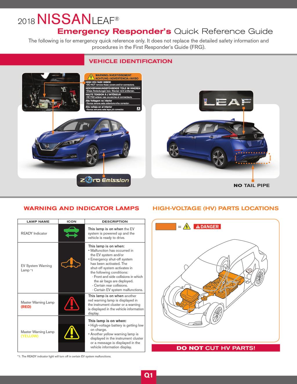
7 1-2 Vehicle Identification Number(VIN) Layout The vehicle identification number can be located as follows: Example VIN : 1N4A Z1CPXJC The LEAF is identified by the 5 th alphanumeric character:z Z = Electric vehicle 1. VIN plate (visible through windshield) 2. Vehicle certification label (lower center pillar) 1-3 Warning and Indicator Lamp Information The following warning and indicator lamps are located in the instrument cluster. Lamp Name Icon Description READYIndicator TGAAYIA0035ZZ This lamp is on when the EVsystem is powered up and the vehicle is ready to drive. EV System Warning Lamp*1 Master Warning Lamp (RED) Malfunction has occurred in the EV system and/or Emergency shut-off system has been activated. The shut-off system activates in the following conditions: Front and side collisions in which the air bags are deployed. Certain rear collisions. Certain EV system malfunctions. This lamp is on when another red warning lamp is displayed in the instrument cluster or a warning is displayed on the vehicle information display. Master Warning Lamp (YELLOW) This lamp is on when: High-voltage battery is getting low on charge. A yellow warning lamp is displayed in the instrument cluster or a message is displayed on the vehicle information display. *1: The READY indicator light will turn off in certain EV system malfunctions. FRG 7
8 2. Basic High-Voltage System and 12-volt System Information 2-1 High-Voltage-Related and 12-volt-Related Component Locations and Descriptions NOTE: TGAAYIA0048ZZ Components with white number in black background are high-voltage components. FRG 8
9 No. Component Location Description ➊ Charge port Under hood Connecting port for EVSE (Electric Vehicle Supply Equipment). Two ports are available: Normal charge and quick charge (if so equipped). ➋ Traction Motor Under hood Converts three-phase AC power to drive power (torque) which propels the vehicle. Inverter Under hood Converts the DC power stored in the highvoltage battery to three-phase AC power and controls motor torque (revolution) by regulating the motor current. Electric air conditioner compressor Power Delivery Module (PDM) On Board Charger DC/DC Converter High-voltage junction box (J/B) Under hood Under hood Air conditioner compressor The PDM includes an On Board Charger, DC/DC converter and high-voltage junction box (J/B). The On Board Charger converts singlephase AC power from a home power outlet to DC power and increases the voltage in order to charge the high-voltage battery. The DC/DC converter reduces the voltage of the high-voltage battery to provide power to the 12-volt battery in order to operate the vehicle's electric components (headlights, audio system, etc.). The J/B provides electric power from the high-voltage battery to all high-voltage parts of the vehicle. ➂ 12-volt Battery Under hood A lead-acid battery that supplies power to the low voltage devices. ➍ High-voltage cables Under hood and undercarriage ➎ Cabin heater Interior (This unit is installed behind the instrument panel) ➏ ➐ ➇ High-voltage battery High-voltage battery service disconnect Brake power supply backup unit Undercarriage Rear seat floor Cargo area (This unit is installed behind a trim panel to prevent access) Orange-colored power cables carry highvoltage current between each of the highvoltage components. This is the electric heat source for the cabin heater. It heats the interior of the vehicle. Stores and outputs DC power (Maximum voltage 420V) needed to propel the vehicle. Isolates the battery from the rest of the high-voltage electrical system. Power supply backup unit for the brake system. It supplies power to the brake system if a malfunction occurs in the 12-volt battery. FRG 9
 48 60.90 x 46.77 x 10.39 in.")
10 2-1.1 High-Voltage Battery Pack Specifications High-voltage battery voltage Number of high-voltage battery modules in the pack High-voltage battery dimensions High-voltage battery weight 2-2 High-Voltage Safety Measures Circuit insulation Reducing the risk of electrocution Identification WarningLabels (240V- 420V usable range) x x in.(1547 x 1188 x 264 mm) US: lbs (303 kg) Canada: lbs (305 kg) The high-voltage positive (+) and negative (-) circuits are insulated from the metal chassis. The high-voltage components and harnesses have insulated cases or orange-colored coverings which provide insulation and easy identification. The high-voltage battery case is electrically connected to the vehicle ground. This connection helps protect the vehicle occupants and emergency responders from high-voltage electrical shock. The high-voltage components are labeled WARNING similar to label shown below. All high-voltage harnesses are coated in orange. The following warning label is applied to the power delivery module (PDM) located under hood. TGAAYIA0055ZZ FRG 10


11 The following warning label is applied to the service plug access cover located in the rear seat floor. The following warning label is applied to the high-voltage battery located on the vehicle s undercarriage. AAYIA0455ZZ AAYIA0456ZZ FRG 11
12 2-3 High-Voltage Circuit Shut-Off System The high-voltage can be shut off by the following methods: Service plug System main relay (located in high-voltage battery) Emergency shut-off system Charging connector 2-4 Preventing Electrical Shock Positioned in the center area of the high-voltage battery, this shuts off output high-voltage when manually removed. Controlled by the power switch, this relay, which is controlled by the 12-volt system, shuts off the high-voltage from the high-voltage battery. In the case of a collision (front and side collisions in which the air bags are deployed, certain rear collisions) or certain system malfunctions this system is designed to shut off the high-voltage from the high-voltage battery. Some of the high-voltage components are activated during charging. Remove the charging connector to deactivate these components. 1. If it is necessary to touch any of the high-voltage harnesses or components,you must always wear appropriate Personal Protective Equipment (PPE) (refer to 3-1 Preparation Items (FRG 14)) and shut off the high-voltage system by referring to High-voltage System Shut-Down Procedures (FRG 18). 2. To avoid the risk of electrocution, NEVER touch the inside of the high-voltage battery unless appropriate PPE is worn even after shutting off the high-voltage system. The high-voltage battery maintains charge even though the high-voltage system is shut down. 3. Cover any damaged high-voltage components with insulated tape. 2-5 Emergency Medical Equipment The high-voltage system should not interfere with emergency medical equipment which must be used in or near the vehicle at an accident scene. FRG 12
13 3. Emergency Response Steps Failure to properly shut down the high-voltage electrical system before the Emergency Response Procedures are performed will result in serious injury or death from electrical shock. To prevent serious injury or death, NEVER touch high-voltage harnesses or components without always wearing appropriate Personal Protective Equipment(PPE). If it is necessary to touch any of the high-voltage harnesses or components you must always wear appropriate PPE to avoid electrical shock. Shut down the high-voltage system by following the steps outlined in High-voltage System Shut-Down Procedures(FRG 18). Wait at least ten(10) minutes for complete discharge of the high-voltage capacitor after the high-voltage system has been shut down. NEVERassumetheLEAFisshutOFFsimplybecauseitisquiet. If the READY indicator or charging indicator are ON, the high-voltage system is active. If possible, be sure to verify that the READY indicator on the instrument cluster is OFF and the high-voltage system is stopped. Someoftheunderhoodpartsgethotandmaycauseseriousburns.Usecaution when working on or around these parts. FRG 13
. To protect insulated gloves Wrenches Size:10mm To remove the service plug access cover bolts.")

14 3-1 PreparationItems Preparation Items Specification Purpose Personal Protective Equipment (PPE): Insulated gloves Insulated shoes Up to 1,000V For protection from highvoltage electrical shock Safety shield Leather gloves Must be able to fasten tight around the wrist (worn over insulated gloves). To protect insulated gloves Wrenches Size:10mm To remove the service plug access cover bolts. To remove the 12-volt battery terminal bolt. Solvent resistant protection gloves Solvent resistant protection shoes Absorbent pad Standard fire fighting equipment The same pad used for internal combustion engine fluids can be used. Standard fire fighting equipment Depending on type of fire (vehicle or battery) use standard fire fighting equipment (water or extinguisher). To utilize in the event of a high-voltage battery electrolytic solution leak. To absorb any high-voltage battery electrolytic solution leakage. To extinguish a fire. Insulated tape Insulating To cover any damaged harnesses to protect from and prevent electrical shock. Tape should cover all bare or damaged wire. FRG 14
15 3-1.1 Personal Protective Equipment(PPE) Protective Wear Control Perform an inspection of the Personal Protective Equipment (PPE) items before beginning work.do not use any damaged PPE items DailyInspection This inspection is performed before and after use. The responder who will be using the items should perform the inspection and check for deterioration and damage. Insulated rubber gloves should be inspected for scratches, holes and tears.(visual check and air leakage test) Insulated safety boots should be inspected for holes, damage, nails, metal pieces, wear or other problems on the soles.(visual check) Insulated rubber sheet should be inspected for tears.(visual check) InsulatedTools When performing work at locations where high-voltage is applied (such as terminals), use insulated tools meeting 1,000V/300A specifications. FRG 15

16 3-2 Vehicle Immobilization and Stabilization If possible,immobilize the vehicle by turning the 12Vsystem OFF and stabilize it with a wheel chock(s). Stabilize the vehicle with cribbing, by removing air from the tires, or utilize the Lift Airbag Equipment for rescue. Do not stabilize the vehicle with cribbing under the high-voltage battery. To avoid electrical shock, do not put the Lift Airbag Equipment for rescue and wheel chock(s) under the high-voltage components and harnesses as shown following. TGAAYIA0013GB FRG 16
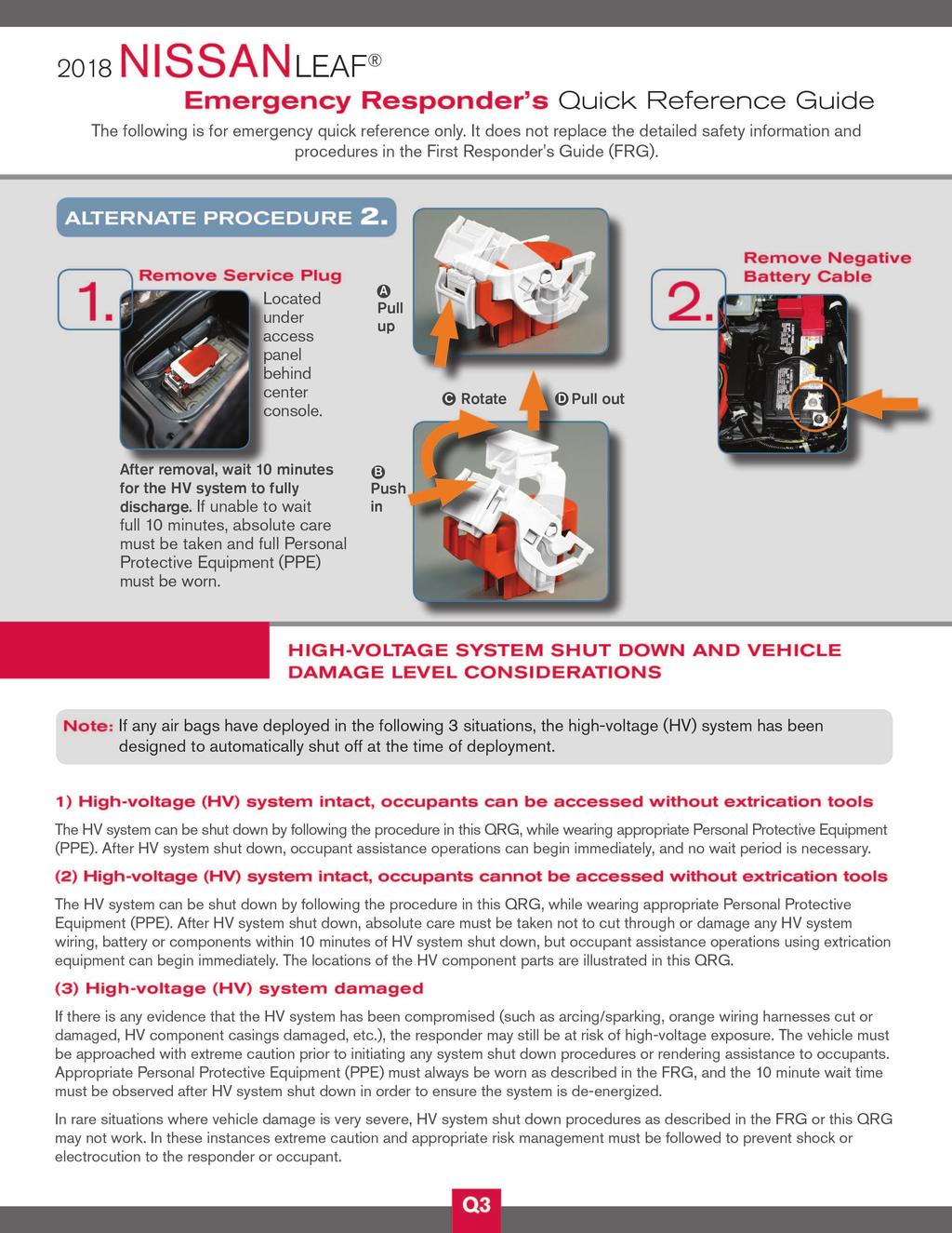
17 3-3 How to Handle a Damaged Vehicle at an Accident Scene NOTE: If any air bags have deployed in the following 3 situations, the high-voltage(hv) system has been designed to automatically shut off at the time of deployment. The Nissan LEAF high-voltage system incorporates capacitors which are energized whenever the high-voltage system is on. If the high-voltage system is shut down (either through one of the built-in automatic mechanisms or manually through one of the procedures explained in this FRG), the capacitors will begin to gradually discharge. After 5 minutes, the voltage level will have dropped below 60V, and complete discharge requires approximately 10 minutes after high-voltage system shut down. It is within this period of time that responders must be most cautious. When arriving to an incident involving a Nissan LEAF, the vehicle should be approached with caution and inspected for the level of damage. In addition to overall vehicle condition (location and severity of body damage, air bag deployment, etc.), the high-voltage system should be assessed specifically. The locations of the high-voltage component parts are illustrated in this FRG. Refer to 2-1 High-Voltage-Related and 12-volt-Related Component Locations and Descriptions (FRG 8). Appropriate Personal Protective Equipment (PPE) must always be worn when approaching a vehicle of unknown condition, as described in this FRG. Situation 1) High-voltage system intact, occupants can be accessed without extrication tools The HVsystem can be shut down by following the procedures in this guide,while wearing appropriate PPE. After HV system shut down, occupant assistance can begin immediately, and no wait period is necessary. Situation 2) High-voltage system intact, occupants cannot be accessed without extrication tools The HVsystem can be shut down by following the procedure in this guide,while wearing appropriate PPE.After HVsystem shut down,absolute care must be taken not to cut through or damage any HVsystem wiring,battery or components withinten(10)minutesofhv system shut down, but occupant assistance operations using extrication equipment can begin immediately. The locations of the HV components are illustrated in this guide. Situation 3) High-voltage(HV) system damaged If there is any evidence that the HV system has been compromised (such as arcing/sparking, orange wiring harnesses cut or damaged, HV component casings damaged, etc.), the responder may still be at risk of high-voltage exposure. The vehicle must be approached with extreme caution prior to initiating any system shut down procedures or rendering assistance to occupants. Appropriate PPE must always be worn as described in this guide, and theten(10)minutewaittimemustbeobservedafterhvsystemshutdowninorderto ensure the system is de-energized. In rare situations where vehicle damage is very severe, HV system shut down procedures as described in this guide may not work. In these instances extreme caution and appropriate risk management must be followed to prevent shock or electrocution to the responder or occupant. FRG 17
18 3-3.1 High-voltage System Shut-Down Procedures Any of the following procedures can shut down and isolate the high-voltage system. The first response operation should only begin after shutting down the high-voltage system. If the vehicle is heavily damaged, for example the high-voltage battery is deformed, broken or cracked, appropriate Personal Protective Equipment (PPE) must always be used and the highvoltage battery and high-voltage components must not be touched. Failure to properly shut down the high-voltage system before the Emergency Response Procedures are performed will result in serious injury or death from electrical shock. To prevent serious injury or death, NEVER touch highvoltage harnesses or components without always wearing appropriate Personal Protective Equipment(PPE). PPE must always be worn when touching or working on high-voltage components When contact with high-voltage components or high-voltage harnesses is unavoidable,orwhenthereisriskofsuchcontact,youmustalwayswear appropriate PPE. PPE must always be worn when touching or working on highvoltage components. FRG 18
19 If the charge connector is connected to the vehicle, remove it. Refer to Removing the Charge Connector(FRG 20). The vehicle contains parts that contain powerful magnets. If a person who is wearing a pacemaker or other medical device is close to these parts, the medical devicemaybeaffectedbythemagnets.suchpersonsmustnotperformworkonthe vehicle. Be sure to verify that the READY stopped. indicator is off and the high-voltage system is After the high-voltage system is shut down, please wait at least ten(10) minutes for complete discharge of the high-voltage capacitor. While waiting, do not operate any vehicle functions. NOTE: The high-voltage full discharge takes ten(10) minutes, but after five(5) minutes the voltage has dropped below 60V. After shutting down the high-voltage system and removing the 12-volt battery negative(-) terminal, wait at least three(3) minutes to discharge the air bag capacitor. Even though the 12-volt battery negative(-) is disconnected, the Supplemental Restraint System(SRS) air bag maintains voltage at least three(3) minutes.duringthistime,thereisapossibilityofsuddensrsairbaginflationdueto harness short circuit or damage and it may cause serious injuries. Always shut down the high-voltage system before disconnecting the 12-volt battery. Not doing so may result in serious injury or death from electrical shock. The 12V system will remain active even after the 12-volt battery negative(-) terminal is removed while the high-voltage system is active. The high-voltage system is active during any of the following conditions: charging indicator is turned ON READY indicator is turned ON Refer to Interior Component Location(FRG 6) for location of these indicators. ThisisbecauseDC/DCconverterwillnotshutdownandpowerwillbesuppliedtothe 12V system and high-voltage system continuously. FRG 19
 NOTE: The quick charger must be OFF to release the charge connector lock. Release the quick connector lock and pull to remove.")
20 Removing the Charge Connector NOTE: Use the illustration to identify the type of charge connector and follow the appropriate procedure. 1. Quick Charge Connector(If So Equipped) NOTE: The quick charger must be OFF to release the charge connector lock. Release the quick connector lock and pull to remove. Refer to the quick charger label or instructions. 2. Trickle and Normal Charge Connectors a. Press the charge connector release button on the charge connector and pull to remove. NOTE: If the charge connector cannot be removed, the electric lock is engaged. Follow the next steps to disengage. b. To disengage the electric charge connector lock, push the charge port lid opener switch. The charge connector will temporarily unlock for 30 seconds. TGAAYIA0021GB TGAAYIA0050ZZ FRG 20
21 c. The charge connector can be unlocked by pushing the charge connector unlock button on the Nissan Intelligent Key for more than 1 second. The charge connector will temporarily unlock for 30 seconds. d. Press the charge connector release button and pull the charge connector to remove it. TGAAYIA0012GB 3. If the Trickle or Normal Charge Connector Cannot Unlock a. Place power switch in OFF position. AAYIA0091ZZ b. Open the hood. TGAAYIA0033ZZ FRG 21

22 c. Using a flat head screwdriver (or suitable tool), insert into the screw located through the access hole near the front of the hood lock. d. Rotate screw clockwise to release the charge connector lock. e. Press the charge connector release button and pull the charge connector to remove it. TGAAYIA0049ZZ Indications the High-voltage System is ON 1. If the READY indicator is ON, the high-voltage system is active. 2. The high-voltage system is active if any charge indicator is ON (blue LEDs on top of the instrument panel). TGAAYIA0026ZZ Before disconnecting the 12-volt battery terminal, if necessary, lower the windows, unlock the doors, and open the rear hatch as required. Once 12-volt battery is disconnected, power controls will not operate. Powering Down the High-voltage System The high-voltage system can be shut down with any 1 of the following procedures: Turn OFF the power switch and disconnect the 12-volt battery. Refer to Primary Procedure (FRG 23). Remove the fuses for the high-voltage control system and disconnect the 12-volt battery. Refer to Alternate Procedure 1 (Remove Fuses) (FRG 24). Remove the service plug and disconnect the 12-volt battery. Refer to Alternate Procedure 2 (Remove Service Plug) (FRG 26). FRG 22

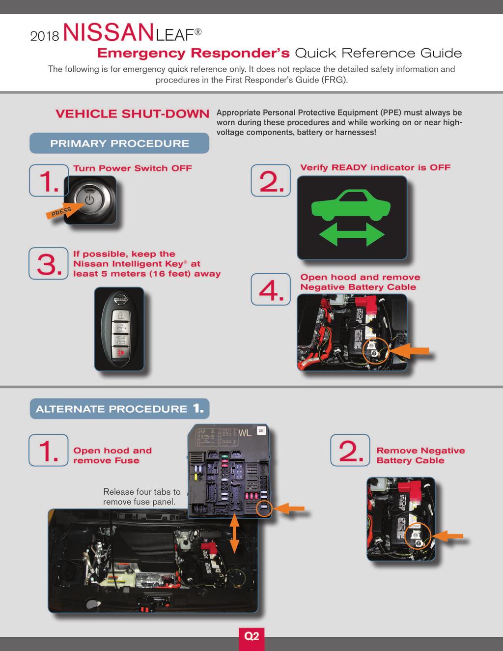
23 Primary Procedure 1. Check the READY indicator status. If it is ON, the high-voltage system is active. 2. Place the selector lever in the Park (P) position. 3. Press the power switch once to turn OFF the high-voltage system. Then verify whether the READY indicator is OFF and continue to the next steps to open the hood for 12-volt battery negative cable access. If the READYindicator does not turn off,refer to Alternate Procedure 1 (Remove Fuses) (FRG 24) 4. If possible, keep the Nissan Intelligent Key at least 5 meters (16 feet) away from the vehicle. AAYIA0091ZZ 5. Open the hood. TGAAYIA0012GB 6. Disconnect the negative (-) 12-volt battery cable ( 1). Insulate the negative (-) battery cable terminal with insulated tape. NOTE: : Arrow in illustration depicts vehicle front direction. TGAAYIA0033ZZ TGAAYIA0034ZZ 7. Wait at least ten(10) minutes for complete discharge of the high-voltage capacitor after the power switch has been turned OFF. 8. Perform the first response action FRG 23

24 Alternate Procedure 1(Remove Fuses) 1. Open the hood. 2. Press and expand the pawls (A) on the sides of the fuse box and remove the fuse box (1) from its housing. TGAAYIA0033ZZ TGAAYIA0029ZZ NOTE: : Arrow in illustration depicts vehicle front direction. NOTE: Thereisnoseparatefuseboxcover.Thebottomofthefuseboxisalsoitscover. FRG 24
25 3. Remove F/S1 RLYFuse (F24 F/S1 RLY15A). TGAAYIA0017GB 4. If you cannot identify the above fuse,remove all fuses in the fuse boxes. 5. Disconnect the negative (-) 12-volt battery cable ( 1). Insulate the negative (-) battery cable terminal with insulated tape. NOTE: : Arrow in illustration depicts vehicle front direction. TGAAYIA0034ZZ 6. Wait at least ten(10) minutes for complete discharge of the high-voltage capacitor after the fuses are pulled. 7. Perform the first response action. To avoid unintended reinstallation and risk of electrical shock and severe personal injuryordeath,therescuershouldcarrythefusesonhis/herpersonandcoverthefuse box with insulated tape. FRG 25
26 Alternate Procedure 2(Remove Service Plug) Do not remove the service plug without always wearing appropriate Personal Protective Equipment(PPE) to help protect the responder from serious injury or death by electrical shock. Immediately cover the service plug socket with insulated tape. The highvoltage battery retains high-voltage power even when the service plug is removed. To avoid electric shock, NEVER touch the terminals inside the socket. To avoid unintended reinstallation and risk of electrical shock and severe personal injury or death, the rescuer should carry the service plug on his/her person while work is in progress. 1. Insert a suitable tool (1) under the RH rear corner of the access trim cover located on the floor behind the center console.pry up (2) and remove. NOTE: : Arrow in illustration depicts vehicle front direction. 2 1 AAYIA0159ZZ 2. Remove the 10 mm access cover bolts (1) and remove the cover (2). 1 NOTE: : Arrow in illustration depicts vehicle front direction. 2 AAYIA0158ZZ FRG 26
27 3. Remove the service plug using the following steps:(1) pull up and release the green lever,(2) press the locking tab to release and rotate fully upward,(3) pull the service plug completely out of its socket Pull up Push to release Rotate Pull up and remove AAYIA0048GB 4. Wait at least(10) minutes for complete discharge of the high-voltage capacitor after the service plug has been removed. 5. Open the hood. 6. Disconnect the negative (-) 12-volt battery cable ( 1). Insulate the negative (-) battery cable terminal with insulated tape. NOTE: : Arrow in illustration depicts vehicle front direction. TGAAYIA0033ZZ 7. Perform the first response action. TGAAYIA0034ZZ FRG 27
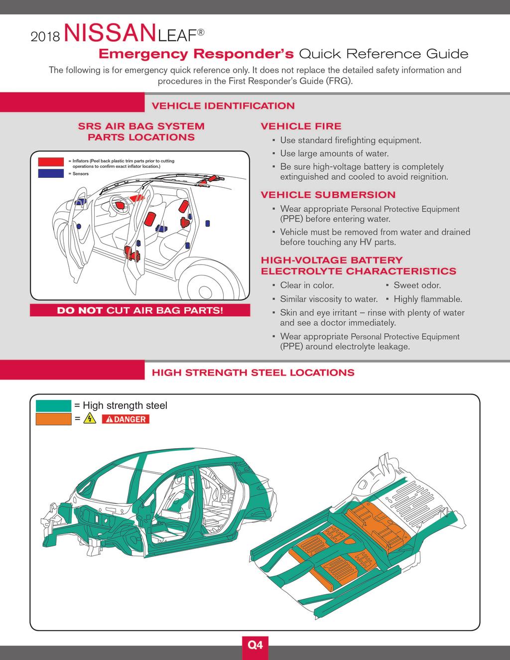
28 3-3.2 WaterSubmersion Damage level of submerged vehicle may not be apparent. Handling a submerged vehicle without appropriate Personal Protective Equipment(PPE) will result in serious injury or death from electrical shock. ThepowerswitchofthesubmergedvehiclemustbeturnedOFFfirst,if possible.thenthevehiclemustbecompletelyoutofthewateranddrainedto avoid electrical shock. Always wear appropriate Personal Protective Equipment(PPE) and remove/ drainwaterbeforeremovingtheserviceplugwhenworkingonavehicleaftera fire or submersion to avoid electrical shock. Ifthevehicleisinthewater,toavoidelectricalshockNEVERtouchthehighvoltage components, harnesses or service plug. PPE must always be worn when touching or working on high-voltage components VehicleFire Always utilize full Personal Protective Equipment(PPE) and self-contained breathing apparatus during fire fighting operations. Smoke from a LEAF vehicle fire is similar to smoke from a conventional vehicle fire. Inthecaseofextinguishingafirewithwater,largeamountsofwaterfromafire hydrant(ifpossible)mustbeused.donotextinguishfirewithasmallamountof water. Intheeventofasmallfire,aTypeABCfireextinguishermaybeusedforanelectrical fire caused by wiring harnesses, electrical components, etc. or oil fire. Fire attack should follow standard fire fighting practices. If you must walk away from the vehicle,notify an appropriate responder or a rescue person of the fact that the vehicle is an electric car and contains a high-voltage system and warn all others. During overhaul operations (late stage fire suppression process to examine for remaining sources of heat), make sure the battery is fully cooled to avoid fire re-ignition. The battery could reignite if it is placed near fire. To avoid possible electrical shock and serious personal injury, do not breach the high-voltage battery case. FRG 28
29 3-3.4 Cutting the Vehicle Body Do not cut into high-voltage related areas to avoid severe personal injury or death. Do not cut into the high-voltage battery to avoid severe personal injury or death. When removing parts, NEVER touch the high-voltage parts or the insides of the exposed orange-colored high-voltage cables to avoid severe personal injury or death. Personal Protective Equipment(PPE) must always be worn when touching or working on high-voltage components. Donotcutairbagpartstoavoidunintendeddeploymentoftheairbagsandtherisk of severe personal injury or death. If at least ten(10) minutes have passed since the rescuer shut down the high-voltage system (refer to High-voltage System Shut-Down Procedures (FRG 18)), then the rescuer can cut the vehicle except for the high-voltage battery. Iftherescuercannotwaitthefullten(10)minutesorshutdownthehigh-voltagesystem, absolute care must be taken to avoid cutting HV parts and appropriate Personal Protective Equipment(PPE) must always be worn.do NOT cut the high-voltage battery due to possible electrocution risk and electrolyte solution leakage. FRG 29
30 SRS Air Bag System Components Location Avoid cutting air bag system parts. However, the vehicle can be cut (except inflators) under the following conditions: The front,side and curtain air bags have deployed. At least three (3) minutes have passed after the 12-volt battery negative (-) cable has been disconnected and the high-voltage system has been shut down. TGAAYIA0011GB FRG 30
31 TGAAYIA0046ZZ 1. Crash zone sensor 2. Supplemental front-impact air bag modules 4. Roof-mounted curtain side-impact supplemental air bag modules 7.Seat belts with pretensioners (front seats) 10.Air bag control unit (ACU) 5. Roof-mounted curtain side-impact supplemental air bag inflators 8.Seat belts with pretensioners (front seats) 3. Front seat-mounted sideimpact supplemental air bag modules 6. Front door satellite sensors 9. Rear satellite sensors (located in lower B-pillars and C-pillars) FRG 31

32 Vehicle Cut Sheet TGAAYIA0020GB FRG 32

33 High Strength Steel Locations TGAAYIA0032ZZ FRG 33
34 3-3.5 High-voltage Battery Damage and Fluid Leaks The high-voltage battery contains electrolyte solution. To avoid exposure to electrolyte solution and serious personal injury, always wear appropriate solvent resistant Personal Protective Equipment(PPE) and read the following precautions: Electrolyte solution is a skin irritant. Electrolyte solution is an eye irritant If contact with eyes, rinse with plenty of water and see a doctor immediately. If electrolyte leak occurs, wear appropriate solvent resistant PPE and use a dry cloth to clean up the spilled electrolyte. Be sure to adequately ventilate the area. Electrolyte solution is highly flammable Electrolyte liquid or fumes that have come into contact with water vapors in the air will create an oxidized substance. This substance may irritate skin and eyes. Inthesecases,rinsewithplentyofwaterandseeadoctorimmediately. Electrolyte fumes(when inhaled) can cause respiratory irritation and acute intoxication.movetofreshairandwashmouthwithwater.seeadoctor immediately. If electrolyte solution leakage, or damage such as any problem with the high-voltage battery casing are observed, first responders should attempt to neutralize the battery by applying a large volume of water to the battery pack while wearing appropriate Personal Protective Equipment (PPE). The neutralization process helps stabilize the thermal condition of the battery pack but does not discharge the battery. High-voltage Battery Electrolyte Solution Characteristics: Clear in color Sweet odor Similar viscosity to water Since the high-voltage battery is made up of many small sealed battery modules, electrolyte solution leakage should be minimal. NOTE: Otherfluidsinthevehiclearethesameasthoseinaconventionalinternal combustion vehicle Accessing the Occupants 1. Remove windows a. Perform window removal the same as a normal vehicle. 2. Remove doors a. The doors are removable with hand tools or basic rescue tools such as electrical/hydraulic rescue tools. It may be easier to remove the doors by cutting door hinges. FRG 34
35 3. Adjust steering wheel and front seat position (if necessary) a. To adjust steering wheel,push the lock lever down (1) and adjust the steering wheel up or down (2). TGAAYIA0051ZZ b. Manual front seat can be adjusted forward/backward by pulling up and holding lever (1) and tilted forward/backward by pulling up and holding lever (2). 1 2 AAYIA0146ZZ c. Power front seat can be adjusted as shown. NOTE: Before disconnecting the 12-volt battery terminal, if necessary, lower the windows, adjust the driver power seat, unlock the doors, etc. Once 12-volt battery is disconnected, power controls will not operate. FRG 35
36 TGAAYIA0052ZZ 4. Remove front seat head restraint (if necessary). The front seat head restraint can be removed by pressing the lock knob and pulling it up. AAYIA0079ZZ 5. Unfasten the seat belt. Seat belt can be unfastened by pressing the release button. If seat belt cannot be unfastened, cut it with a belt cutter. AAYIA0080ZZ 3-4 Storing The Vehicle For vehicle storage information, refer to Roadside Assistance Guide or Dismantling Guide located at or FRG 36
37 4. Emergency Quick Reference Guide The following is for emergency quick reference only. It does not replace the detailed safety information and procedures in this manual. FRG 37
38 TGAAYIA0007GB
39 TGAAYIA0008GB
40 TGAAYIA0009GB
41 TGAAYIA0010GB

42 2017 Nissan North America, Inc. All rights reserved. This document may not be altered without the written permission of Nissan North America, Inc. Pub. No. FR18EA0ZE0U0
2013 LEAF. First Responder s Guide
 2013 LEAF First Responder s Guide 1 Foreword This manual describes first response operations and related warnings for this vehicle. This vehicle is an electrically driven car equipped with a high voltage
2014 e-nv200. First Responder s Guide
 2014 e-nv200 First Responder s Guide Foreword This manual describes first response operations and related warnings for this vehicle. This vehicle is an electrically driven car equipped with a high voltage
2013 M35h HYBRID. Dismantling Guide
 2013 M35h HYBRID Dismantling Guide 1 Foreword This manual describes dismantling operations and important safety related warnings and cautions for this vehicle. This vehicle is equipped with a high voltage
2017LEAF. Dismantling Guide
 2017LEAF Dismantling Guide Foreword This manual describes dismantling operations and important safety related warnings for this vehicle. This vehicle is an electrically driven car equipped with a high-voltage
You may see various symbols in this manual. They have the following meanings:
 Dismantling Guide 1 Foreword This manual describes dismantling operations and related warnings and cautions for this vehicle. This vehicle is an electrically driven car equipped with a high voltage battery
2017QX60HYBRID. Dismantling Guide
 2017QX60HYBRID Dismantling Guide Foreword This manual describes dismantling operations and important safety related warnings and cautions for this vehicle. This vehicle is equipped with a high-voltage
2017QX60HYBRID. Roadside Assistance Guide
 2017QX60HYBRID Roadside Assistance Guide Foreword This manual describes roadside assistance operations and important safety related warnings and cautions for this vehicle. This vehicle is equipped with
Roadside Assistance Guide
 Roadside Assistance Guide 1 Foreword This manual describes roadside assistance operations and related warnings and cautions for this vehicle. This vehicle is an electrically driven car equipped with a
ELECTRIC VEHICLE DISMANTLING MANUAL
 iq EV Electric Vehicle ELECTRIC VEHICLE DISMANTLING MANUAL KPJ10 Series Foreword This guide was developed to educate and assist dismantlers in the safe handling of Scion/Toyota iq EV electric vehicles.
Contents. Introduction... Document Purpose... Vehicle Description... Soul Electric Vehicle Identification... General Vehicle Description...
 Contents Introduction............................................... Document Purpose..................................................... Vehicle Description......................................................
Emergency Response Guide
 Emergency Response Guide 2013 ILX Hybrid Prepared for Fire Service, Law Enforcement, Emergency Medical, and Professional Towing Personnel by Honda Canada Inc. Introduction This information has been prepared
Emergency Response Guide
 Emergency Response Guide NEW THINKING. NEW POSSIBILITIES. Contents Introduction 1 IONIQ electric Identification - General Vehicle Description - Identifying a Hyundai electric vehicle 2 2 2 IONIQ electric
ELECTRIC VEHICLE DISMANTLING MANUAL
 RAV4 EV Electric Vehicle ELECTRIC VEHICLE DISMANTLING MANUAL QEA38 Series Foreword This guide was developed to educate and assist dismantlers in the safe handling of Toyota RAV4 EV electric vehicles. RAV4
Emergency Rescue Guide Manual
 Emergency Rescue Guide Manual Contents Introduction Document Purpose......................................................... Vehicle Description.........................................................
Emergency Rescue Guide Manual
 Emergency Rescue Guide Manual Contents Introduction................................................. Document Purpose......................................................... 1 1 Vehicle Description.........................................................
Emergency Rescue Guide Manual
 Emergency Rescue Guide Manual Contents Introduction Document Purpose......................................................... Vehicle Description.........................................................
C>r>E: s EMERGENCY RESPONSE GUIDE
 2016+ C>r>E: s EMERGENCY RESPONSE GUIDE This guide is intended only for use by trained and certified rescuers and first responders. It assumes that readers have a comprehensive understanding of how safety
2017~ Honda NSX Emergency Response Guide
 2017~ Honda NSX Emergency Response Guide Honda Motor Europe Ltd. All Rights Reserved. Version 1(0816) Introduction This guide has been prepared to assist emergency service professionals in identifying
2018 Honda Clarity Plug-In Hybrid Emergency Response Guide
 2018 Honda Clarity Plug-In Hybrid Emergency Response Guide Prepared for Fire Service, Law Enforcement, Emergency Medical, and Professional Towing Personnel 2017 American Honda Motor Co., Inc. All Rights
2017 Acura MDX Sport Hybrid Emergency Response Guide. Prepared for Fire Service, Law Enforcement, Emergency Medical, and Professional Towing Personnel
 2017 Acura MDX Sport Hybrid Emergency Response Guide Prepared for Fire Service, Law Enforcement, Emergency Medical, and Professional Towing Personnel 2017 American Honda Motor Co., Inc. All Rights Reserved.
2018 Honda Accord Hybrid Emergency Response Guide
 2018 Honda Accord Hybrid Emergency Response Guide Prepared for Fire Service, Law Enforcement, Emergency Medical, and Professional Towing Personnel 2018 American Honda Motor Co., Inc. All Rights Reserved.
Foreword About the Nissan Altima Hybrid Altima Hybrid Identification Hybrid System Battery Information High Voltage Safety
 Foreword... - 3 - About the Nissan Altima Hybrid... - 4 - Altima Hybrid Identification... - 5 - VIN Location... - 5 - Engine Compartment... - 6 - Exterior... - 7 - Interior... - 7 - Hybrid System... -
Plug-in. Emergency Response Guide
 Plug-in Emergency Response Guide NEW THINKING. NEW POSSIBILITIES. Contents Introduction 1 IONIQ Plug-in Hybrid Identification - General Vehicle Description - Identifying a Hyundai Plug-in Hybrid vehicle
C>r>E: X EMERGENCY RESPONSE GUIDE
 2016 C>r>E: X EMERGENCY RESPONSE GUIDE This guide is intended only for use by trained and certified rescuers and first responders. It assumes that readers have a comprehensive understanding of how safety
Acura NSX Emergency Response Guide
 2017 18 Acura NSX Emergency Response Guide Prepared for Fire Service, Law Enforcement, Emergency Medical, and Professional Towing Personnel Supersedes 2017 Acura NSX Emergency Response Guide, dated June
Honda Clarity Electric Emergency Response Guide
 2017 18 Honda Clarity Electric Emergency Response Guide Prepared for Fire Service, Law Enforcement, Emergency Medical, and Professional Towing Personnel Supersedes 2017 Honda Clarity Electric Emergency
Gasoline-Electric Hybrid
 Gasoline-Electric Hybrid Foreword This guide was developed to educate and assist emergency responders in the safe handling of the Toyota Prius gasoline-electric hybrid vehicle following an incident. Prius
Emergency Response Guide
 Emergency Response Guide For Hybrid Vehicles Prepared for fire service, law enforcement, emergency medical, and professional towing personnel by American Honda Motor Co., Inc. Introduction This booklet
RAV4 EV. Electric 2012 Model 2 nd Generation
 . RAV4 EV Electric 2012 Model 2 nd Generation 2012 Toyota Motor Corporation All rights reserved. This document may not be altered without the written permission of Toyota Motor Corporation. 12 Toyota RAV4
C>r>E: X EMERGENCY RESPONSE GUIDE
 C>r>E: X EMERGENCY RESPONSE GUIDE This guide is intended only for use by trained and certified rescuers and first responders. It assumes that readers have a comprehensive understanding of how safety systems
The information in this guide will allow response to emergencies involving Balance Hybrid E450 vehicles.
 Introduction The emergency response procedures for the Balance Hybrid E450 vehicle are similar to those for traditional gasoline-powered vehicles with the addition of special considerations for the high-voltage
2014, Acura RLX Sport Hybrid Emergency Response Guide
 2014, 2016 18 Acura RLX Sport Hybrid Emergency Response Guide Prepared for Fire Service, Law Enforcement, Emergency Medical, and Professional Towing Personnel NOTE: Acura did not produce this model for
Emergency Response Guide
 Emergency Response Guide For Hybrid Vehicles 2011 Model Year Edition Contents Introduction 1 Part 1: Information for All Honda Hybrids Vehicle Description 2 Identifying a Honda Hybrid 2 Gasoline Engine
EMERGENCY RESPONSE GUIDE
 2012-2013 EMERGENCY RESPONSE GUIDE This guide is intended only for use by trained and certified rescuers and first responders. It assumes that readers have a comprehensive understanding of how safety systems
MITSUBISHI i-miev Emergency Response Guide. Lithium-Ion Battery Electric Vehicle. Copyright 2014, Mitsubishi Motors North America, Inc.
 MITSUBISHI 2014 i-miev Emergency Response Guide Lithium-Ion Battery Electric Vehicle Copyright 2014, Mitsubishi Motors North America, Inc. May 2014 Introduction This manual provides safety instructions
iq EV Electric 2013 Model 13 Scion iq EV ERG REV (09/03/12)
") iq EV Electric 2013 Model 2012 Toyota Motor Corporation All rights reserved. This document may not be altered without the written permission of Toyota Motor Corporation. 13 Scion iq EV ERG REV (09/03/12)
iq EV Electric 2013 Model 2012 Toyota Motor Corporation All rights reserved. This document may not be altered without the written permission of Toyota Motor Corporation. 13 Scion iq EV ERG REV (09/03/12)
Emergency Response Guide
 Plug-in Emergency Response Guide NEW THINKING. NEW POSSIBILITIES. Contents Introduction Sonata Plug-in Hybrid Identification - General Vehicle Description - Identifying a Hyundai Plug-in Hybrid 2 2 2 Sonata
Emergency Response Guide
 Emergency Response Guide 2014 2015 Accord Accord Hybrid Hybrid Prepared for Fire Service, Law Enforcement, Emergency Medical, and Professional Towing Personnel by American Honda Motor Co., Inc. Introduction
Emergency Response Guide
 Emergency Response Guide Honda Gasoline-Electric Hybrid Vehicle Prepared for Fire Service, Law Enforcement, Emergency Medical, and Professional Towing Personnel by American Honda Motor Co., Inc. Contents
2016Q70HYBRID. Dismantling Guide
 2016Q70HYBRID Dismantling Guide Foreword This manual describes dismantling operations and important safety related warnings and cautions for this vehicle. This vehicle is equipped with a high voltage battery
Emergency Response Guide
 Emergency Response Guide 2014-2016 Acura RLX Sport Hybrid Prepared for Fire Service, Law Enforcement, Emergency Medical, and Professional Towing Personnel by Honda Canada Inc. Introduction This guide has
2006 Model. 06Highlander Hybrid ERG REV (08/17/05)
") 2006 Model 2005 Toyota Motor Corporation All rights reserved. This document may not be altered without the written permission of Toyota Motor Corporation. 06Highlander Hybrid ERG REV (08/17/05) Foreword
2006 Model 2005 Toyota Motor Corporation All rights reserved. This document may not be altered without the written permission of Toyota Motor Corporation. 06Highlander Hybrid ERG REV (08/17/05) Foreword
Gasoline-Electric Hybrid Synergy Drive
 Gasoline-Electric Hybrid Synergy Drive ZWE150 Series Foreword This guide was developed to educate and assist dismantlers in the safe handling of Toyota Auris gasoline-electric hybrid vehicles. Auris hybrid
South Magellan Drive, Torrance, California USA
 Prepared by: DJ / ND Reviewed/ Approved by: AS Page 1 of 17 SV520002R 101207 www.enovasystems.com 19850 South Magellan Drive, Torrance, California 90502 USA Copyright Prepared by: DJ / ND Reviewed/ Approved
Special Post Crash Safety Considerations
 Special Post Crash Safety Considerations Emergency responders should check a vehicle for markings or other indications that it is electric-powered. If it is, they should exercise caution, per published
Gasoline-Electric Hybrid Synergy Drive
 Gasoline-Electric Hybrid Synergy Drive ZVW30 Series Foreword This guide was developed to educate and assist dismantlers in the safe handling of Toyota Prius gasoline-electric hybrid vehicles. Prius dismantling
Nissan Altima Hybrid
 Nissan Altima Hybrid 2009 NISSAN NORTH AMERICA, INC. All rights reserved. This document may not be altered without the written permission of NISSAN NORTH AMERICA, INC. Pub. No. FR0E-1H32U0-1 - Foreword...
Chevrolet Equinox Fuel Cell. Emergency Response Guide
 Chevrolet Equinox Fuel Cell Emergency Response Guide 1 This guide specifically addresses the Chevrolet Equinox Fuel Cell. While a majority of the systems installed on these vehicles are common to traditional
Emergency Response Guide
 Emergency Response Guide Honda Gasoline-Electric Hybrid Vehicle Prepared for Fire Service, Law Enforcement, Emergency Medical, and Professional Towing Personnel by American Honda Motor Co., Inc. Contents
PRIUS PRIME PRIUS PHV
 PRIUS PRIME PRIUS PHV Plug-in Hybrid Gasoline-Electric Hybrid Synergy Drive ZVW52 Series Foreword This guide was developed to educate and assist dismantlers in the safe handling of Toyota PRIUS PRIME,
Plug-in Hybrid 2010 Model Revised (includes 2012 Model)
") Plug-in Hybrid 2010 Model Revised (includes 2012 Model) 2012 Toyota Motor Corporation All rights reserved. This document may not be altered without the written permission of Toyota Motor Corporation. Prius
Plug-in Hybrid 2010 Model Revised (includes 2012 Model) 2012 Toyota Motor Corporation All rights reserved. This document may not be altered without the written permission of Toyota Motor Corporation. Prius
Hybrid 2006 Model. 06RX 400hERG REV (05/27/05)
") Hybrid 2006 Model 2005 Toyota Motor Corporation All rights reserved. This document may not be altered without the written permission of Toyota Motor Corporation. 06RX 400hERG REV (05/27/05) Foreword In
Hybrid 2006 Model 2005 Toyota Motor Corporation All rights reserved. This document may not be altered without the written permission of Toyota Motor Corporation. 06RX 400hERG REV (05/27/05) Foreword In
2006/2007 ESCAPE HYBRID OR MARINER HYBRID
 2006/2007 ESCAPE HYBRID OR MARINER HYBRID EMERGENCY RESPONSE GUIDE 1 FOREWORD Escape Hybrid or Mariner Hybrid emergency response procedures are similar to those for a traditional gasoline powered vehicle
Gasoline-Electric Hybrid Synergy Drive
 Gasoline-Electric Hybrid Synergy Drive NHW20 Series Foreword This guide was developed to educate and assist dismantlers in the safe handling of the Toyota Prius gasoline-electric hybrid vehicle. Prius
ESCAPE HYBRID EMERGENCY RESPONSE GUIDE. Version 1.0
 ESCAPE HYBRID EMERGENCY RESPONSE GUIDE Version 1.0 1 FOREWORD Escape Hybrid emergency response procedures are similar to those for a traditional gasoline powered vehicle with the exception of the high
Gasoline-Electric Hybrid
 Gasoline-Electric Hybrid Foreword This guide was developed to educate and assist emergency responders in the safe handling of the Toyota Prius gasoline-electric hybrid vehicle following an incident. Prius
Gasoline-Electric Hybrid
 Gasoline-Electric Hybrid Foreword This guide was developed to educate and assist emergency responders in the safe handling of the Toyota Prius gasoline-electric hybrid vehicle following an incident. Prius
2004 Model 2 nd Generation
 2004 Model 2 nd Generation Emergency Response Guide 2004 Toyota Motor Corporation All rights reserved. This document may not be altered without the written permission of Toyota Motor Corporation. 04PRIUSERG
2004 Model 2 nd Generation
 2004 Model 2 nd Generation Emergency Response Guide 2004 Toyota Motor Corporation All rights reserved. This document may not be altered without the written permission of Toyota Motor Corporation. 04PRIUSERG
2009 ESCAPE HYBRID MARINER HYBRID
 2009 ESCAPE HYBRID MARINER HYBRID EMERGENCY RESPONSE GUIDE 1 FOREWORD The emergency response procedures for the Escape Hybrid and Mariner Hybrid vehicles are similar to those for traditional gasoline-powered
HYBRID VEHICLE BATTERY
 HYBRID BATTERY X HYBRID BATTERY NICKEL METAL HYDRIDE HYBRID VEHICLE BATTERY Hybrid Vehicle (HV) Battery Pack. Wear Protective safety clothing at all times! The 300 Series Hybrid contains a high voltage
Eaton Hybrid First Responder Training Eaton. All rights reserved.
 Eaton Hybrid First Responder Training Outline Eaton Hybrid History Identifying a Hybrid High-Voltage Components Emergency Procedures Emergency Contact and Recycling Built-In Safety Features Towing or Jumpstarting
South Magellan Drive, Torrance, California USA
 SV400003R Prepared by: Reviewed/ Approved by: Page 1 of 21 www.enovasystems.com 19850 South Magellan Drive, Torrance, California 90502 USA SV400003R Prepared by: Reviewed/ Approved by: Page 2 of 21 FOREWORD
Gasoline-Electric Hybrid Synergy Drive
 Gasoline-Electric Hybrid Synergy Drive GWS191 Series Foreword This guide was developed to educate and assist dismantlers in the safe handling of the Lexus GS450h gasoline-electric hybrid vehicle. GS450h
Emergency Services Guidance for Competition Electric Vehicles
 NEDRA Technical Information Bulletin 2013.001 Emergency Services Guidance for Competition Electric Vehicles Authors Michael Dunn Technical Director National Electric Drag Racing Association tech@nedra.com
Gasoline-Electric Lexus Hybrid Drive
 Gasoline-Electric Lexus Hybrid Drive GYL10/GYL15 Series Foreword This guide was developed to educate and assist dismantlers in the safe handling of Lexus RX450h gasoline-electric hybrid vehicles. RX450h
CAMRY Hybrid. Gasoline-Electric Hybrid Synergy Drive. AXVH71 Series
 CAMRY Hybrid Gasoline-Electric Hybrid Synergy Drive AXVH71 Series Foreword This guide was developed to educate and assist dismantlers in the safe handling of Toyota CAMRY Hybrid gasoline-electric hybrid
Removal & Installation
 Page 1 of 11 2011 Nissan Rogue : Body > Interior > Instrument Panel > Removal & Installation Removal & Installation 1. Before servicing the vehicle, refer to the Precautions Section. CAUTION Always work
IS300h. Gasoline-Electric Hybrid Synergy Drive. AVE30 Series
 IS300h Gasoline-Electric Hybrid Synergy Drive AVE30 Series Foreword This guide was developed to educate and assist dismantlers in the safe handling of Lexus IS300h gasoline-electric hybrid vehicles. IS300h
TRIBUTE HYBRID EMERGENCY RESPONSE GUIDE ERG-08HEV
 TRIBUTE HYBRID EMERGENCY RESPONSE GUIDE CONTENTS TRIBUTE HYBRID EMERGENCY RESPONSE GUIDE FOREWORD...- 1 - TRIBUTE HYBRID VEHICLE IDENTIFICATION... - 3 - HIGH-VOLTAGE ELECTRICAL AND FUEL DISCONNECT FEATURES...
AVALON Hybrid. Gasoline-Electric Hybrid Synergy Drive. AVX40 Series
 AVALON Hybrid Gasoline-Electric Hybrid Synergy Drive AVX40 Series Foreword This guide was developed to educate and assist dismantlers in the safe handling of Toyota AVALON Hybrid gasoline-electric hybrid
LC500h. Gasoline-Electric Lexus Hybrid Drive. GWZ100 Series
 LC500h Gasoline-Electric Lexus Hybrid Drive GWZ100 Series Foreword This guide was developed to educate and assist dismantlers in the safe handling of Lexus LC500h gasoline-electric hybrid vehicles. LC500h
2012 Buick LaCrosse eassist 2012 Buick Regal eassist
 2012 Buick LaCrosse eassist 2012 Buick Regal eassist GM Service Technical College provides First Responder Guides (FRG) and Quick Reference (QR) Sheets free of charge to First Responders. FRGs and QRs
2014 Cadillac ELR. GM s First Responder Guides are available at
 2014 Cadillac ELR GM Service Technical College provides First Responder Guides (FRG) and Quick Reference (QR) Sheets free of charge to First Responders. FRGs and QRs can be displayed in a classroom as
FOCUS ELECTRIC EMERGENCY RESPONSE GUIDE. FCS Focus Electric Emergency Response Guide - 01/2017 Copyright Ford 2017 FoMoCo
 2017 FOCUS ELECTRIC EMERGENCY RESPONSE GUIDE TABLE OF CONTENTS INTRODUCTION SECTIONS. High-Voltage Electrical System Information. High-Voltage Service Disconnect. High-Voltage Charge Cord Lock Manual Release.
PRIUS. Gasoline-Electric Hybrid Synergy Drive. ZVW50/ZVW51 Series
 PRIUS Gasoline-Electric Hybrid Synergy Drive ZVW50/ZVW51 Series Foreword This guide was developed to educate and assist dismantlers in the safe handling of Toyota PRIUS gasoline-electric hybrid vehicles.
Emergency Response Guide
 Eaton Hybrid Transmissions More time on the road Emergency Response Guide Eaton Hybrid Transmissions TRDR1100 March 2009 Warnings and Cautions Warnings & Cautions Throughout this manual there are paragraphs
Holden Volt Emergency Response Guide 9/11/12
 Holden Volt Emergency Response Guide 9/11/12 1 Course Overview Duration: 2 hours Course Content: Vehicle Introduction Battery and Electrical Technology Emergency Operations Response to the Incident 2 Course
Berlingo First Electric. Safety procedures to be observed with an accident-damaged vehicle where the traction battery may be damaged
 Berlingo First Electric Safety procedures to be observed with an accident-damaged vehicle where the traction battery may be damaged CONTENTS 1 VEHICLE IDENTIFICATION... 4 1.1 External Identification...4
SUPPLEMENTAL RESTRAINT SYSTEM (SRS)
") RESTRAINTS SECTION SRS A SUPPLEMENTAL RESTRAINT SYSTEM (SRS) B C D CONTENTS E PRECAUTION... 2 PRECAUTIONS... 2 Precaution for Supplemental Restraint System (SRS) "AIR BAG" and "SEAT BELT PRE-TEN- SIONER"...2
RESTRAINTS SECTION SRS A SUPPLEMENTAL RESTRAINT SYSTEM (SRS) B C D CONTENTS E PRECAUTION... 2 PRECAUTIONS... 2 Precaution for Supplemental Restraint System (SRS) "AIR BAG" and "SEAT BELT PRE-TEN- SIONER"...2
Gasoline-Electric Hybrid Synergy Drive
 Gasoline-Electric Hybrid Synergy Drive MHU23/28 Series Foreword This guide was developed to educate and assist dismantlers in the safe handling of the Toyota Highlander gasoline-electric hybrid vehicle.
2011 Chevrolet Volt .
 2011 Chevrolet Volt GM Service Technical College provides First Responder Guides (FRG) and Quick Reference (QR) Sheets free of charge to First Responders. FRGs and QRs can be displayed in a classroom as
2013 Chevrolet Malibu Eco with eassist
 2013 Chevrolet Malibu Eco with eassist GM Service Technical College provides First Responder Guides (FRG) and Quick Reference (QR) Sheets free of charge to First Responders. FRGs and QRs can be displayed
VENTILATION SYSTEM SECTION VTL CONTENTS VENTILATION, HEATER & AIR CONDITIONER VTL-1 PRECAUTION... 3 PREPARATION... 5 SYSTEM DESCRIPTION...
 VENTILATION, HEATER & AIR CONDITIONER SECTION VTL A VENTILATION SYSTEM B C D CONTENTS E PRECAUTION... 3 PRECAUTIONS... 3 Precaution for Supplemental Restraint System (SRS) "AIR BAG" and "SEAT BELT PRE-TEN-
SRS AIRBAG SECTION SR CONTENTS RESTRAINTS SR-1 PRECAUTION... 2 PREPARATION... 4 REMOVAL AND INSTALLATION... 5
 RESTRAINTS SECTION SR A SRS AIRBAG B C D CONTENTS E PRECAUTION... 2 PRECAUTIONS... 2 Precaution for Supplemental Restraint System (SRS) "AIR BAG" and "SEAT BELT PRE-TEN- SIONER"...2 Precaution Necessary
VENTILATION SYSTEM SECTION VTL CONTENTS VENTILATION, HEATER & AIR CONDITIONER VTL-1 SYSTEM DESCRIPTION... 3 PRECAUTION... 6 PREPARATION...
 VENTILATION, HEATER & AIR CONDITIONER SECTION VTL A VENTILATION SYSTEM B C D CONTENTS E SYSTEM DESCRIPTION... 3 AUTOMATIC AIR CONDITIONER SYSTEM... 3 WITH COLOR DISPLAY...3 WITH COLOR DISPLAY : Switches
2011 ESCAPE HYBRID MARINER HYBRID EMERGENCY RESPONSE GUIDE
 2011 ESCAPE HYBRID MARINER HYBRID EMERGENCY RESPONSE GUIDE 1 FOREWORD The emergency response procedures for the Escape Hybrid and Mariner Hybrid vehicles are similar to those for traditional gasoline-powered
Hybrid 2012 Model 2 nd Generation
 Hybrid 2012 Model 2 nd Generation 2011 Toyota Motor Corporation All rights reserved. This document may not be altered without the written permission of Toyota Motor Corporation. 12 Camry Hybrid ERG REV
IMA Technical Information and Emergency Handling Guide
 IMA Technical Information and Emergency Handling Guide Preface This manual describes procedures to be followed when performing emergency procedures rescuing people from a CR-Z hybrid vehicle. For safety,
VENTILATION SYSTEM SECTION VTL CONTENTS VENTILATION, HEATER & AIR CONDITIONER VTL-1 PRECAUTION... 2 PREPARATION... 4 FUNCTION DIAGNOSIS...
 VENTILATION, HEATER & AIR CONDITIONER SECTION VTL A VENTILATION SYSTEM B C D CONTENTS E PRECAUTION... 2 PRECAUTIONS... 2 Precaution for Supplemental Restraint System (SRS) "AIR BAG" and "SEAT BELT PRE-TEN-
Hybrid 2007 Model CAMRY Hybrid ERG REV - (6/19/06)
") Hybrid 2007 Model 2006 Toyota Motor Corporation All rights reserved. This document may not be altered without the written permission of Toyota Motor Corporation. 2007 CAMRY Hybrid ERG REV - (6/19/06) Foreword
Hybrid 2007 Model 2006 Toyota Motor Corporation All rights reserved. This document may not be altered without the written permission of Toyota Motor Corporation. 2007 CAMRY Hybrid ERG REV - (6/19/06) Foreword
Gasoline-Electric Hybrid Synergy Drive
 Gasoline-Electric Hybrid Synergy Drive GWL10 Series Foreword This guide was developed to educate and assist dismantlers in the safe handling of Lexus GS450h gasoline-electric hybrid vehicles. GS450h dismantling
Emergency Response Guide
 XV Crosstrek Hybrid Hybrid 2014 Model Emergency Response Guide 2013 Fuji Heavy Industries Ltd. All rights reserved. This document may not be altered without the written permission of Subaru. Publication
NX300h. Gasoline-Electric Hybrid Synergy Drive. AYZ10/AYZ15 Series
 NX300h Gasoline-Electric Hybrid Synergy Drive AYZ10/AYZ15 Series Foreword This guide was developed to educate and assist dismantlers in the safe handling of Lexus NX300h gasoline-electric hybrid vehicles.
2019 FUSION HYBRID MKZ HYBRID FUSION ENERGI EMERGENCY RESPONSE GUIDE
 2019 FUSION HYBRID MKZ HYBRID FUSION ENERGI EMERGENCY RESPONSE GUIDE Table of Contents FOREWORD... 2 HYBRID VEHICLE IDENTIFICATION... 3-4 VIN Layout...5 HIGH-VOLTAGE ELECTRICAL DISCONNECT FEATURES... 6
2017 FUSION HYBRID MKZ HYBRID FUSION ENERGI EMERGENCY RESPONSE GUIDE
 2017 FUSION HYBRID MKZ HYBRID FUSION ENERGI EMERGENCY RESPONSE GUIDE FCS-15129-17 Table of Contents FOREWORD... Page 2 HYBRID VEHICLE IDENTIFICATION... Pages 3-4 VIN Layout...Page 5 HIGH-VOLTAGE ELECTRICAL
BODY SHOP ADMINISTRATION MANUAL FOR CERTIFIED EV DEALER
 Draft as of Aug. 19 th,2010 Update as of Sep. 21 st,2010 Final Version as of Oct.15 th,2010 Revised Version as of Nov.12 nd,2010 BODY SHOP ADMINISTRATION MANUAL FOR CERTIFIED EV DEALER Global Aftersales
Travis County Emergency Services District #1 Standard Operating Guidelines
 Section Policy Number Effective Date F F4 07/10/2015 Policy Issued As Reference Policy # B3, C13, TBD Subject Approval: Donald Norman, Fire Chief PURPOSE The purpose of this section is to; give basic knowledge
Hybrid 2012 Model. 12 Toyota Prius V ERG REV (17/06/11)
") Hybrid 2012 Model 2011 Toyota Motor Corporation All rights reserved. This document may not be altered without the written permission of Toyota Motor Corporation. 12 Toyota Prius V ERG REV (17/06/11) Foreword
Hybrid 2012 Model 2011 Toyota Motor Corporation All rights reserved. This document may not be altered without the written permission of Toyota Motor Corporation. 12 Toyota Prius V ERG REV (17/06/11) Foreword
2013 C-MAX HYBRID C-MAX ENERGI EMERGENCY RESPONSE GUIDE
 2013 C-MAX HYBRID C-MAX ENERGI EMERGENCY RESPONSE GUIDE FCS-21236-13 SEPTEMBER/2012 Table of Contents FOREWORD...Page 1 ELECTRIC VEHICLE IDENTIFICATION...Page 2 VIN Layout... Page 3 HIGH-VOLTAGE ELECTRICAL