You may see various symbols in this manual. They have the following meanings:
|
|
|
- Solomon Carr
- 6 years ago
- Views:
Transcription

1 Dismantling Guide 1
2 Foreword This manual describes dismantling operations and related warnings and cautions for this vehicle. This vehicle is an electrically driven car equipped with a high voltage battery pack. Failure to follow recommended practices during dismantling will cause death or serious personal injury. Please read this manual in advance in order to understand the features of this vehicle and to help you deal with dismantling operations involving this vehicle. Follow the procedures in order to help assure a successful dismantling operation. NISSAN EMERGENCY CONTACT INFORMATION Nissan EV Customer Support: (Hours of operation are Monday-Friday 7am - 7pm, Saturday 8am - 4:30pm Central time zone) Nissan Consumer Affairs: (US) or (Canada) (Hours of operation are 8am - 5pm (Monday-Friday) Eastern, Central and Pacific time zones) IMPORTANT INFORMATION ABOUT THIS MANUAL You may see various symbols in this manual. They have the following meanings: This symbol is used to inform you of an operation which will result in death or serious personal injury if instructions are not followed. Example: Touching high voltage components without using the appropriate protective equipment will result in electrocution. This symbol is used to inform you of an operation which may cause death or serious personal injury if instructions are not followed. This symbol is used to inform you of an operation which may cause personal injury or component damage if instructions are not followed. Please note that there may be differences between this manual and the vehicle specification due to specification changes. 2
3 Table of Contents FOREWORD NISSAN EMERGENCY CONTACT INFORMATION IMPORTANT INFORMATION ABOUT THIS MANUAL ABOUT THE NISSAN LEAF LEAF IDENTIFICATION EXTERIOR INTERIOR COMPONENT LOCATION VEHICLE IDENTIFICATION NUMBER (VIN) LAYOUT WARNING AND INDICATOR LAMP INFORMATION BASIC HIGH VOLTAGE INFORMATION HIGH VOLTAGE-RELATED AND 12V-RELATED COMPONENT LOCATIONS AND DESCRIPTIONS LI-ION BATTERY PACK SPECIFICATIONS HIGH VOLTAGE SAFETY MEASURES WARNING LABEL HIGH VOLTAGE CIRCUIT SHUT-OFF SYSTEM PREVENTING ELECTRICAL SHOCK PREPARATION FOR DISMANTLING DISCHARGING PROCEDURES PREPARATION ITEMS HIGH VOLTAGE SYSTEM SHUT-DOWN PROCEDURE REMOVING THE CHARGE CONNECTOR INDICATIONS THE HIGH VOLTAGE SYSTEM IS ON POWERING DOWN THE HIGH VOLTAGE SYSTEM PRIMARY PROCEDURE ALTERNATE PROCEDURE ALTERNATE PROCEDURE CUTTING THE VEHICLE BODY SRS AIR BAG SYSTEM COMPONENTS LOCATION VEHICLE CUT SHEET WATER SUBMERSION VEHICLE FIRE LI-ION BATTERY DAMAGE AND FLUID LEAKS JUMP STARTING JUMP STARTING PROCEDURES
4 4-2 ELECTRIC PARKING BRAKE MECHANICAL RELEASE PROCEDURE P (PARK) POSITION RELEASE PROCEDURE RESET PROCEDURE STORING THE VEHICLE DISMANTLING INFORMATION PRECAUTIONS FOR HANDLING HIGH VOLTAGE LITHIUM ION (LI-ION) BATTERY PPE (PERSONAL PROTECTIVE EQUIPMENT) AND INSULATED TOOLS PPE (PERSONAL PROTECTIVE EQUIPMENT) PROTECTIVE WEAR CONTROL DAILY INSPECTION INSULATED TOOLS LITHIUM-ION (LI-ION) BATTERY PACK REMOVAL EXPLODED VIEW REMOVAL PROCEDURE RECOVERY/RECYCLING OF THE LI-ION HIGH VOLTAGE BATTERY
5 1. About The Nissan LEAF This vehicle uses two types of batteries. One is a 12V battery that is the same as the battery in vehicles powered by internal combustion engines, and the other is the Lithium-ion (Li-ion) battery (high voltage) for the traction motor which propels the vehicle. The Li-ion battery is encased in steel and mounted underneath the vehicle. The vehicle must be plugged-in in order for the Li-ion battery to be recharged. Additionally, the vehicle system can recharge the Li-ion battery by converting driving force into electricity while the vehicle is decelerating or being driven downhill. This is called regenerative charging. This vehicle is considered to be an environmentally friendly vehicle because it does not emit exhaust gases. 5

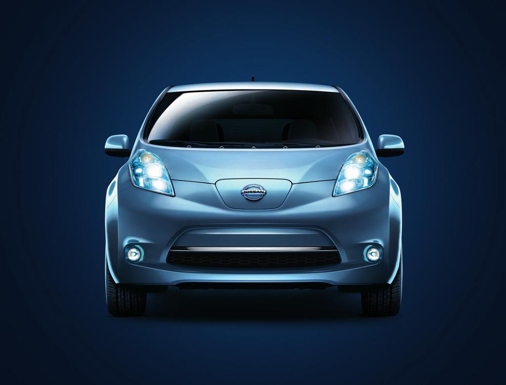
6 1-1 LEAF Identification Exterior The specific exterior identification features are indicated as follows: 6

7 1-1.2 Interior Component Location Interior components referenced in this manual are as follows: 7
 2.")


8 1-2 Vehicle Identification Number (VIN) Layout The vehicle identification number can be located as follows: Example VIN : JN1A Z0CP3BT The LEAF is identified by the 5 th alphanumeric character: Z Z = Electric vehicle 1. VIN plate (visible through windshield) 2. Vehicle certification plate (lower center pillar) 1-3 Warning and Indicator Lamp Information The following warning and indicator lamps are located in the instrument cluster. Lamp Name Icon Description READY Indicator This lamp is on when the EV system is powered up and the vehicle is ready to drive. EV System Warning Lamp *1 Master Warning Lamp (RED) Master Warning Lamp (YEL- LOW) Malfunction has occurred in the EV system and/or Emergency shut-off system has been activated. The shut-off system activates in the following conditions: Front and side collisions in which the air bags are deployed. Certain rear collisions. Certain EV system malfunctions. This lamp is on when another red warning lamp is displayed in the instrument cluster or a warning is displayed on the dot matrix LCD. This lamp is on when: Li-ion battery is getting low on charge. A yellow warning lamp is displayed in the instrument cluster or a message is displayed on the dot matrix LCD. *1: When this lamp is ON, the ready lamp will turn OFF. 8

9 2. Basic High Voltage Information 2-1 High Voltage-Related and 12V-Related Component Locations and Descriptions NOTE: Components with white number in black background are high voltage components. 9
10 No. Component Location Description a Traction Motor Under hood Converts three-phase AC power to drive power (torque) which propels the vehicle. b DC/DC Converter High voltage junction box Under hood This component includes a DC/DC converter and high voltage junction box (J/B). The junction box provides electric power from the Li-ion battery to all high voltage parts of the vehicle. The DC/DC converter reduces the voltage of the Li-ion battery to provide power to the 12V battery in order to operate the vehicle s electric components (headlights, audio system, etc.). c Inverter Under hood Converts the DC power stored in the Li-ion battery to three-phase AC power and controls motor torque (revolution) by regulating the motor current. d Electric air conditioner compressor Under hood Air conditioner compressor e Cabin heater Under hood This is the electric heat source for the cabin heater. It heats the interior of the vehicle. f Charge port Under hood Connecting port for EVSE (Electric Vehicle Supply Equipment). Two ports are available: Normal charge and quick charge (if so equipped). 7 12V Battery Under hood A lead-acid battery that supplies power to the low voltage devices. h Li-ion (Lithium ion) battery i High voltage cables j High voltage battery service disconnect k On Board Charger 12 Brake power supply backup unit Undercarriage Undercarriage and Under hood Rear seat floor Cargo area (This unit is installed behind a trim panel to prevent access) Cargo area (This unit is installed behind a trim panel to prevent access) Li-ion Battery Pack Specifications Stores and outputs DC power (Maximum voltage 400V) needed to propel the vehicle. Orange-colored power cables carry high voltage current between each of the high voltage components. Isolates the battery from the rest of the high voltage electrical system. Converts single-phase AC power from a home power outlet to DC power and increases the voltage in order to charge the Li-ion battery. Power supply backup unit for the brake system. It supplies power to the brake system if a malfunction occurs in the 12V battery. Li-ion battery voltage 403.2V Number of Li-ion battery modules in the pack 48 Li-ion battery dimensions 61.8 x 46.8 x 10.4 in. ( x 1188 x mm) Li-ion battery weight 648 lbs (294 kg) 10

11 2-2 High Voltage Safety Measures Circuit insulation The high voltage positive (+) and negative (-) circuits are insulated from the metal chassis. Reducing the risk of electrocution The high voltage components and harnesses have insulated cases or orange-colored coverings which provide insulation and easy identification. The high voltage battery case is electrically connected to the vehicle ground. This connection helps protect the vehicle occupants and emergency responders from high voltage electrical shock. Identification Warning Label The high voltage components are labeled WARNING similar to label shown below. All high voltage harnesses are coated in orange. 11
12 2-3 High Voltage Circuit Shut-Off System The high voltage can be shut off by the following methods: Service plug System main relay Emergency shut-off system Charging connector Positioned in the center area of the Li-ion battery, this shuts off output high voltage when manually removed. Controlled by the power switch, this relay, which is controlled by the 12V system, shuts off the high voltage from the Li-ion battery. In the case of a collision (front and side collisions in which the air bags are deployed, certain rear collisions) or certain system malfunctions this system may shut off the high voltage from the Li-ion battery. Some of the high voltage components are activated during charging. Remove the charging connector to deactivate these components. 2-4 Preventing Electrical Shock 1. If it is necessary to touch any of the high voltage harnesses or components, you must wear appropriate PPE (refer to 3-2 Preparation Items) and shut off the high voltage system by referring to 3-3 High Voltage System Shut-Down Procedure. 2. To avoid the risk of electrocution, do not touch the inside of the Li-ion battery unless appropriate PPE is worn even after shutting off the high voltage system. The Li-ion battery maintains charge even though the high voltage system is shut down. 3. Cover any damaged high voltage components with insulated tape. 12
13 3. Preparation for Dismantling Failure to properly shut down the high voltage electrical system before the Dismantling Procedures are performed will result in serious injury or death from electrical shock. To prevent serious injury or death, DO NOT touch high voltage harnesses or components without wearing appropriate PPE. If it is necessary to touch any of the high voltage harnesses or components you must wear appropriate PPE to avoid electrical shock. Shut down the high voltage system by following the steps outlined in 3-3 High Voltage System Shut-Down Procedure. Wait at least ten (10) minutes for complete discharge of the high voltage capacitor after the high voltage system has been shut down. NEVER assume the LEAF is shut OFF simply because it is quiet. If it becomes necessary for the dismantler to leave the vehicle, place a DANGER sign (for example, refer to 4-4 Storing the Vehicle) on the vehicle to alert other people that the vehicle contains a high voltage battery. If the READY indicator, charging indicator or air conditioning remote timer indicator are ON the high voltage system is active. If possible, be sure to verify that the READY indicator on the instrument cluster is OFF and the high voltage system is stopped. 3-1 Discharging Procedures Do not perform this procedure if the battery is damaged. If you are unsure of battery damage, use extreme caution and wear appropriate PPE. Li-ion battery discharging must take place before dismantling. Sufficient discharging can be achieved by following these steps. 1. Place the selector lever into the Park (P) position 2. Apply the parking brake. 3. Set wheel chocks to ensure the vehicle is completely stopped. 13
 shows higher than half full (7 of 12 gauge lines lit up), continue to next step. b.")
, navigation system and rear window defogger to discharge")
14 4. Apply foot brake and press the ignition switch to turn the system ON. Confirm READY indicator in instrument cluster turns ON. 5. Check Li-ion battery available charge gauge: a. If remaining energy (1) shows higher than half full (7 of 12 gauge lines lit up), continue to next step. b. If remaining energy (2) shows lower than half full (6 of 12 gauge lines lit up), discharging is not needed. 6. Turn ON electric devices such as headlamps, cabin heater (set to the highest temperature and maximum fan speed; do not use AUTO A/C setting), navigation system and rear window defogger to discharge the Li-ion battery. Allow approximately 30 minutes for each line on the available charge gauge to drop. Discharge is complete when the available charge gauge drops to lower than half full (6 of 12 gauge lines lit up). 7. Press the power switch to turn the system OFF. 14
 Nissan Consumer Affairs:")
: Insulated gloves Up to 1,000V For protection from high voltage electrical shock")


15 Please contact following number if the Li-ion battery cannot be discharged. Nissan EV Customer Support: (Hours of operation are Monday - Friday 7am - 7pm, Saturday 8am - 4:30pm Central time zone) Nissan Consumer Affairs: (US) or (Canada) (Hours of operation are 8am - 5pm (Monday - Friday) Eastern, Central and Pacific time zones) 3-2 Preparation Items Preparation Items Specification Purpose PPE (personal protective equipment): Insulated gloves Up to 1,000V For protection from high voltage electrical shock Insulated shoes Safety shield Wrenches Solvent resistant protection gloves Solvent resistant protection shoes Absorbent pad Standard fire fighting equipment Insulated tape Size:10mm The same pad used for internal combustion engine fluids can be used. Standard fire fighting equipment Depending on type of fire (vehicle or battery) use standard fire fighting equipment (water or extinguisher). Insulating To remove the service plug access cover bolts. To remove the 12V battery terminal bolt. To utilize in the event of a Li-ion battery electrolytic solution leak. To absorb any Li-ion battery electrolytic solution leakage. To extinguish a fire. To cover any damaged harnesses to protect from and prevent electrical shock. Tape should cover all bare or damaged wire. 15
16 3-3 High Voltage System Shut-Down Procedure Any of the following procedures can shut down the high voltage system. The dismantling operation can only begin after shutting down the high voltage system. If the vehicle is heavily damaged, for example the Li-ion battery is deformed, broken or cracked, appropriate PPE must be used and the Li-ion battery and high voltage components must not be touched. Failure to properly shut down the high voltage system before the dismantling procedures are performed will result in serious injury or death from electrical shock. To prevent serious injury or death, DO NOT touch high voltage harnesses or components without wearing appropriate PPE. When contact with high voltage components or high voltage harnesses is unavoidable, or when there is risk of such contact, you must wear appropriate PPE. 16
17 If the charge connector is connected to the vehicle, remove it. Refer to Removing the Charge Connector. The vehicle contains parts that contain powerful magnets. If a person who is wearing a pacemaker or other medical device is close to these parts, the medical device may be affected by the magnets. Such persons must not perform work on the vehicle. Be sure to verify that the READY stopped. indicator is off and the high voltage system is There is a possibility of remaining high voltage in the air conditioning system. If the READY indicator is turned OFF and the air conditioning remote timer indicator is turned ON the high voltage system is active. Please ensure that the air conditioning remote timer indicator is turned OFF and the air conditioning system is inactive. After the high voltage system is shut down, please wait at least ten (10) minutes for complete discharge of the high voltage capacitor. While waiting, do not operate any vehicle functions. NOTE: The high voltage full discharge takes ten (10) minutes, but after five (5) minutes the voltage has dropped below 60V. After shutting down the high voltage system and removing the 12V battery negative (-) terminal, wait at least three (3) minutes to discharge the air bag capacitor. Even though the 12V battery negative (-) is disconnected, the Supplemental Restraint System (SRS) air bag maintains voltage at least three (3) minutes. During this time, there is a possibility of sudden SRS air bag inflation due to harness short circuit or damage and it may cause serious injuries. Always shut down the high voltage system before disconnecting the 12V battery. Not doing so may result in serious injury or death from electrical shock. The 12V system will remain active even after the 12V battery negative (-) terminal is removed while the high voltage system is active. The high voltage system is active during any of the following conditions: air conditioning system remote timer indicator is turned ON charging indicator is turned ON READY indicator is turned ON Refer to Interior Component Location for location of these indicators. This is because DC/DC converter will not shut down and power will be supplied to the 12V system and high voltage system continuously. 17
18 3-3.1 Removing the Charge Connector 1. Press the lock release button/lever on the charge connector. NOTE: The quick charge connector is not equipped on all models. 2. Pull the charge connector to remove it Indications the High Voltage System is ON 1. If the charge indicator is ON, the high voltage system is active. 2. If the air conditioning remote timer indicator (located on the HVAC controller) is ON, the high voltage system is active. 3. If the remote controlled climate control system is active, push the power switch to the ON position. This will turn OFF the remote controlled climate control system. NOTE: Remote controlled climate control system is a feature that allows the vehicle owner to activate the climate control system via telematics communication (cell phone, personal computer, etc.). When this system is active, the air conditioning remote timer indicator (located on the HVAC controller) is illuminated. Before disconnecting the 12V battery terminal, if necessary, set the parking brake, lower the windows, unlock the doors, and open the rear hatch as required. Once 12V battery is disconnected, power controls will not operate Powering Down the High Voltage System The high voltage system can be shut down with any 1 of the following procedures: Turn OFF the power switch and disconnect the 12V battery. Refer to Primary Procedure. Remove the fuses for the high voltage control system and disconnect the 12V battery. Refer to Alternate Procedure 1. Remove the service plug and disconnect the 12V battery. Refer to Alternate Procedure 2. 18
19 3-3.4 Primary Procedure 1. Check the READY indicator status. If it is ON, the high voltage system is active. 2. Place the selector lever in the Park (P) position. 3. Press the power switch once to turn OFF the high voltage system. Then verify whether the READY indicator is OFF. 4. If possible, keep the Nissan Intelligent Key at least 5 meters (16 feet) away from the vehicle. NOTE: This step is not necessary if the 12V system is already disabled. 5. Disconnect the negative (-) 12V battery cable (1). Insulate the negative (-) battery cable terminal with insulated tape. 6. Wait at least ten (10) minutes for complete discharge of the high voltage capacitor after the power switch has been turned OFF. 7. Perform the dismantling operation. 19
 on the sides of the fuse box and remove the fuse box (1) from its housing.")
20 3-3.5 Alternate Procedure 1 1. Open the hood. 2. Press and expand the pawls (A) on the sides of the fuse box and remove the fuse box (1) from its housing. NOTE: There is no separate fuse box cover. The bottom of the fuse box is also its cover. 20
 12V battery cable (1). Insulate the negative (-) battery cable terminal with insulated tape. 6.")
21 3. Remove the following fuses: a. VCM IGN fuse (F15 VCM IGN 10A) b. F/S1 RLY Fuse (F24 F/S1 RLY 15A) c. VCM Fuse (F3 VCM 20A) 4. If you cannot identify the above fuses, remove all fuses in the fuse box. 5. Disconnect the negative (-) 12V battery cable (1). Insulate the negative (-) battery cable terminal with insulated tape. 6. Wait at least ten (10) minutes for complete discharge of the high voltage capacitor after the fuses are pulled. 7. Perform the dismantling operation. To avoid unintended installation and risk of electrical shock and severe personal injury or death, thedismantler should carry the fuses on his/her person and cover the fuse box with insulated tape. 21
22 3-3.6 Alternate Procedure 2 Do not remove the service plug without wearing appropriate PPE to help protect the dismantler from serious injury or death by electrical shock. Immediately cover the service plug socket with insulated tape. The Li-ion battery retains high voltage power even when the service plug is removed. To avoid electric shock, DO NOT touch the terminals inside the socket. To avoid unintended installation and risk of electrical shock and severe personal injury or death, thedismantler should carry the service plug on his/her person while work is in progress. 1. Locate the carpet flap (1) behind the center console on the floor raised area. At the notched area (A) pull up on the carpet flap (1). NOTE: Arrow in illustration depicts vehicle front direction. 2. Remove the 10mm access cover bolts (A) and remove the cover (1). NOTE: Arrow in illustration depicts vehicle front direction. 3. Remove the service plug by pressing the locking tab (1) and rotating the handle (2) upward. Using the handle, pull the service plug completely out of its socket. 22
23 4. Wait at least ten (10) minutes for complete discharge of the high voltage capacitor after the service plug has been removed. 5. Open the hood. 6. Disconnect the negative (-) 12V battery cable (1). Insulate the negative (-) battery cable terminal with insulated tape. 7. Perform the dismantling operation. 3-4 Cutting the Vehicle Body Do not cut into high voltage related areas to avoid severe personal injury or death. Do not cut into the Li-ion battery to avoid severe personal injury or death. When removing parts, DO NOT touch the high voltage parts or the insides of the exposed orange-colored high voltage cables to avoid severe personal injury or death. Use the appropriate tools (for example, hydraulic cutter) when cutting the vehicle to help protect the dismantler to avoid severe personal injury or death. Do not cut air bag parts to avoid unintended deployment of the air bags and the risk of severe personal injury or death. If at least ten (10) minutes have passed since thedismantler shut down the high voltage system (refer to 3-3 High Voltage System Shut-Down Procedure ), then the dismantler can cut the vehicle except for the Li-ion battery. DO NOT cut the Li-ion battery due to possible electrocution risk and electrolyte solution leakage. 23
24 3-4.1 SRS Air Bag System Components Location The SRS air bag system must not be cut as there is a risk of short circuit and unintentional deployment of the SRS However, the vehicle can be cut (except inflators) under the following conditions: The front, side and curtain air bags have deployed. At least three (3) minutes have passed after the 12V battery negative (-) cable has been disconnected and the high voltage system has been shut down. 1. Crash zone sensor 2. Supplemental front-impact air bag modules 4. Roof-mounted curtain sideimpact 5. Roof-mounted curtain side- supplemental air bag impact supplemental air bag inflators modules 7. Lap outer pretensioner (driver side only) 10. Air bag control unit (ACU) 3. Front seat-mounted side-impact supplemental air bag modules 6. Front door satellite sensors 8. Seat belt with pretensioner 9. Rear satellite sensors (located in lower B-pillar) 24
25 3-4.2 Vehicle Cut Sheet 25
26 3-4.3 Water Submersion Damage level of submerged vehicle may not be apparent. Handling a submerged vehicle without appropriate PPE will result in serious injury or death from electrical shock. The power switch of the submerged vehicle must be turned OFF first, if possible. Then the vehicle must be completely out of the water and drained to avoid electrical shock. Wear appropriate PPE and remove/drain water before removing the service plug when working on a vehicle after a fire or submersion to avoid electrical shock. If the vehicle is in the water, to avoid electrical shock do not touch the high voltage components, harnesses or service plug Vehicle Fire Always utilize full PPE and self-contained breathing apparatus during fire fighting operations. Smoke from a LEAF vehicle fire is similar to smoke from a conventional vehicle fire. In the case of extinguishing a fire with water, large amounts of water from a fire hydrant (if possible) must be used. DO NOT extinguish fire with a small amount of water. In the event of a small fire, a Type ABC fire extinguisher may be used for an electrical fire caused by wiring harnesses, electrical components, etc. or oil fire. In case of vehicle fire, contact fire department immediately and extinguish the fire if possible. If you must walk away from the vehicle, notify an appropriate responder or a rescue person of the fact that the vehicle is an electric car and contains a high voltage system and warn all others. 26
27 3-5 Li-ion Battery Damage and Fluid Leaks In cases of battery case breach or electrolyte leakage, contact the fire department immediately. If you must walk away from the vehicle, notify an appropriate responder of the fact that the vehicle is an electric car and contains a high voltage system and warn all others. Li-ion Battery Electrolyte Solution Characteristics: Clear in color Sweet odor Similar viscosity to water Skin irritant Eye irritant If contact with eyes, rinse with plenty of water and see a doctor immediately. If electrolyte leak occurs, wear appropriate solvent resistant PPE and use a dry cloth to clean up the spilled electrolyte. Be sure to adequately ventilate the area. Highly flammable Electrolyte liquid or fumes that have come into contact with water vapors in the air will create an oxidized substance. This substance may irritate skin and eyes. In these cases, rinse with plenty of water and see a doctor immediately. Electrolyte fumes (when inhaled) can cause respiratory irritation and acute intoxication. Move to fresh air and wash mouth with water. See a doctor immediately. Since the Li-ion battery is made up of many small sealed battery modules, electrolyte solution leakage should be minimal. 27
28 4. Jump Starting To start the EV system with a booster battery, the instructions and precautions below must be followed. If done incorrectly, jump starting can lead to a 12V battery explosion, resulting in severe personal injury or death. It could also damage your vehicle. Discharged 12V battery may cause the following issues: The instrument cluster cannot be displayed while the power switch is turned ON. The start-up sound is not audible. (The electric car system cannot start.) The Li-ion battery cannot be charged. The vehicle cannot be shifted out of PARK normally. The electric parking brake cannot be either set or released normally. To avoid electrical shock, the high voltage Li-ion battery CANNOT be jump started. Explosive hydrogen gas is always present in the vicinity of the 12V battery. Keep all sparks and flames away from the 12V battery. Do not allow battery fluid to come into contact with eyes, skin, clothing or painted surfaces. Battery fluid is a corrosive sulfuric acid solution that can cause severe burns. If the fluid comes into contact with anything, immediately flush the contacted area with water. The booster battery must be rated at 12 volts. Use of an improperly rated battery can damage the vehicle. Whenever working on or near a 12V battery, always wear suitable eye protectors (for example, goggles or industrial safety spectacles) and remove rings, metal bands, or any other jewelry. Do not lean over the 12V battery when jump starting. Do not attempt to jump start a frozen battery. It could explode and cause serious injury. LEAF is equipped with an automatic cooling fan. It could come on at any time. Keep hands and other objects away from it. Always follow the jump starting instructions below. Failure to do so could result in damage to the DC/DC converter and cause personal injury. Do not use LEAF to jump start another vehicle. Do not attempt to perform a jump start on the 12V battery at the same time that the Li-ion battery is being charged. Doing so may damage the vehicle or charging equipment and could cause an injury. 28
29 4-1 Jump Starting Procedures 1. If the booster battery is in another vehicle (B), position the two vehicles (A and B) to bring their 12V batteries into close proximity to each other. DO NOT allow the two vehicles to touch. 2. If theleaf electric parking brake is not applied and the selector lever is not in the P (Park) position, immobilize the vehicle with wheel chocks. 3. Switch off all unnecessary electrical systems (headlights, heater, air conditioner, etc.). 4. Place the power switch in the OFF position (if possible). If the 12V battery is discharged, the power switch cannot be moved from the OFF position. Connect the jumper cables to the booster vehicle (B) before pushing the power switch. 5. Remove the vent caps on the 12V battery (if so equipped). Cover the battery with a firmly wrung out moist cloth to reduce the hazard of an explosion. 6. Connect jumper cables in the sequence as illustrated (➀ ➁ ➂ ➃). Always connect positive (+) to positive (+) and negative (-) to body ground (for example, as illustrated), not to the 12V battery. Make sure the jumper cables do not touch moving parts in the motor compartment and that the cable clamps do not contact any other metal. 7. Start the engine of the booster vehicle (B). 8. While the booster vehicle (B) engine is running, place the LEAF in READY mode. If the system does not start right away, push the power switch to the OFF position and wait at least 10 seconds before trying again. 9. After starting the EV system, carefully disconnect the negative cable and then the positive cable (➃ ➂ ➁ ➀). Keep the EV system on for over twenty (20) minutes to charge the 12V battery. 10. Replace the vent caps (if so equipped). Be sure to properly dispose of the cloth used to cover the vent holes because it may be contaminated with corrosive acid. 11. If necessary, connect the vehicle to a charging station or EVSE (Electric Vehicle Supply Equipment) to charge the Li-ion battery. The vehicle cannot be driven unless the Li-ion battery is charged. 29
30 NOTE: If it is not possible to turn the LEAF system ON by following this procedure, contact a NISSAN certified LEAF dealer immediately. 4-2 Electric Parking Brake Mechanical Release Procedure If the electric parking brake cannot be released by operating the parking brake switch, the parking brake can be mechanically released. When releasing the electric parking brake mechanically, always confirm that the vehicle is in the P (Park) position.confirm that the vehicle is in the P (Park) position by checking the shift indicator located near the selector lever or the dot matrix liquid crystal display. If the vehicle cannot be placed in the Park position, contact a NISSAN certified LEAF dealer. If the vehicle is in any position other than the P (Park) position, the vehicle may unexpectedly move and may cause serious personal injury or death. If the vehicle cannot be shifted into the P (Park) position, contact a NISSAN certified LEAF dealer. Always perform this procedure after the electric parking brake switch operation indicator turns off. If not, the system may operate unexpectedly and the tool used for mechanical release may move suddenly. This may cause personal injury. To release the parking brake mechanically, turn the power switch to the OFF position and then make sure that the parking brake switch operation indicator turns off. If the vehicle is driven with the electric parking brake applied, the electric parking brake components may overheat and cause a deterioration in electric parking brake effectiveness and premature electric parking brake wear. The electric parking brake mechanical release tool should be used only to release the electric parking brake in an emergency. NOTE: The electric parking brake mechanical release tool can only be used to release the electric parking brake. It cannot be used to apply the electric parking brake. The electric parking brake operation switch indicator may turn OFF 1 minute after the power switch is placed in the OFF position. If the parking brake switch operation indicator does not turn OFF, contact a NISSAN certified LEAF dealer. To release the parking brake mechanically, perform the following procedures Confirm that the vehicle is in the P (Park) position. (Confirm that the vehicle is in the P (Park) position by checking the shift indicator located near the selector lever or the dot matrix liquid crystal display. If the vehicle cannot be placed in the Park position, contact a NISSAN certified LEAF dealer.) 2. Check that the parking brake switch operation indicator does not illuminate. 3. Place power switch in the OFF position.
31 4. Open the rear hatch. 5. Remove the electric parking brake mechanical release tool from the tool set that is located in the cargo area. 6. Remove the luggage floor board from the cargo area. 7. Remove the cap by turning it counterclockwise. 8. Insert the tool and turn it counterclockwise while pushing it in. 9. Continue to turn until it stops and then release. The tool will then return to approximately the same position as it was in before it was turned and release of the parking brake will be completed. Do not turn the tool beyond the point at which it stops. Doing so may result in damage. 10. Return the tool set and vehicle interior parts back to original location. 4-3 P (Park) Position Release Procedure If you need to release the vehicle from the P (Park) position, proceed as follows. When power switch is turned OFF or 12V battery is low, LEAF automatically shifts to P position. NOTE: This procedure requires two (2) people. 1. To start the EV system with a booster battery, refer to 4. Jump Starting. 2. Turn power switch ON by pushing the power switch 2 times without pressing brake pedal. 3. Confirm parking brake is ON (indicator in electric parking brake switch will be ON). 31
 PBW MTR-2 20A (under hood fuse box behind 12V battery) METER 1 10A (in the cabin")
32 4. Place the selector lever in the N (Neutral) position. 5. Close all doors and press the brake pedal. 6. Remove the following 3 fuses: PBW MTR-1 20A (under hood fuse box behind 12V battery) PBW MTR-2 20A (under hood fuse box behind 12V battery) METER 1 10A (in the cabin fuse box) Under Hood Fuse Box Location Cabin Fuse Box Location 32
33 NOTE: Insert a screwdriver wrapped with a protective cloth (A) into the slit (1). Pull to remove the fuse box cover (2). Remove the fuse with the fuse puller (3). 7. Release the electrical parking brake. 8. Turn the power switch OFF. 9. Release brake pedal. Be sure to firmly position wheel chocks when P (Park) position is manually released Reset Procedure 1. Install the 3 fuses removed previously. 2. Turn the power switch ON and wait 5 seconds without pressing the brake pedal. Ensure selector lever is in the N (neutral) position. 3. If 12V battery is low voltage, please charge with battery charger. 4. Turn the power switch OFF and wait 5 seconds. 33
34 4-4 Storing the Vehicle If LEAF needs to be stored or left unattended, the high voltage system must be shut down by removing the service plug (refer to Alternate Procedure 2) and a sign put on the vehicle indicating it isan electric vehicle with high voltage dangers. For example: 34
35 5. Dismantling Information Removal or repair of the high voltage battery requires special tools and specific training. NISSAN strongly recommends that only certified NISSAN dealer technicians perform these operations. 5-1 Precautions for Handling High Voltage Lithium ion (Li-ion) Battery Because LEAF contains a high voltage (Li-ion) battery, there is the risk of electric shock, electric leakage, or similar accidents if the high voltage components or vehicle is handled incorrectly. Be sure to follow the correct work procedures when performing inspection and dismantling. The colors of the high voltage harnesses and connectors are all orange. Orange High Voltage labels are applied to the Li-ion battery and other high voltage devices. Do not touch the Li-ion battery or other high voltage devices without wearing appropriate PPE. Clearly identify the persons responsible for high voltage work and ensure that other persons do not touch the vehicle. When not working, cover high voltage parts with an insulating cover sheet and sign or similar item to prevent other persons from contacting them. The high voltage battery retains high voltage at all times. Be sure to wear appropriate PPE before beginning work on the high voltage system. If it is necessary to touch any of the high voltage harnesses or components you must wear appropriate PPE and properly shut-down the high voltage system by removing the service plug. Be sure to remove the service plug in order to shut-down the high voltage system before performing inspection or dismantling of high voltage system harnesses and parts. Be sure to put the removed service plug in your pocket and carry it with you so another person does not accidentally install it while work is in progress. Immediately insulate disconnected high voltage connectors and terminals with insulated tape. The vehicle contains parts that contain powerful magnets. If a person who is wearing a pacemaker or other medical device is close to these parts, the medical device may be affected by the magnets. Such persons must not perform work on the vehicle. Because this vehicle uses components that contain high voltage and powerful magnetism, do not carry any metal products which may cause short circuits, or any magnetic media (cash cards, credit cards, etc.) which may be damaged when working on the vehicle. Keep removed Li-ion battery packs away from rain to avoid electric shock. If the vehicle is heavily damaged, for example the Li-ion battery is deformed, broken, or cracked; appropriate PPE must be used at all times to avoid electrical shock. Do not heat removed battery packs higher than 158 F (70 C). 35
36 There is the possibility of a malfunction occurring if the vehicle is changed to READY status while the service plug is removed. 5-2 PPE (Personal Protective Equipment) and Insulated Tools PPE (Personal Protective Equipment) Protective Wear Control Perform an inspection of the PPE items before beginning work. Do not use any damaged PPE items Daily Inspection This inspection is performed before and after use. The worker who will be using the items should perform the inspection and check for deterioration and damage. Insulated rubber gloves should be inspected for scratches, holes and tears. (Visual check and air leakage test) Insulated safety boots should be inspected for holes, damage, nails, metal pieces, wear or other problems on the soles. (Visual check) Insulated rubber sheet should be inspected for tears. (Visual check) Insulated Tools When performing work at locations where high voltage is applied (such as terminals), use insulated tools meeting 1,000V/300A specifications. 36
37 5-3 Lithium-ion (Li-ion) Battery Pack Removal Exploded View 1. Bonding plate (Stamp No. 6) 2. Li-ion battery pack 3. Bonding plate (Stamp No. 4) 4. Bonding plate (Stamp No. 2) 5. Battery under cover (center) 6. Battery under cover (front) 7. Clip 8. Battery under cover (rear) 9. Battery mounting bracket LH 10. Battery mounting bracket RH Removal Procedure 1. Raise the vehicle and remove the battery under covers (front, center and rear). 2. Disconnect the high voltage connector (A) from the Li-ion battery. Touching high voltage components without wearing appropriate PPE will cause electrocution. 37
. : Insulated tape 3.")

.")
38 a. Follow procedure below to disconnect the high voltage connector. Cover battery side of high voltage connector with insulated tape (A). : Insulated tape 3. Disconnect the Li-ion battery vehicle communications connector (A) while turning it counterclockwise. Touching high voltage components without wearing appropriate PPE will cause electrocution. 4. Remove the bonding plates (3 locations). NOTE: The bonding plate (1, 2 and 3) shape differs depending on the location of installation. Touching high voltage components without wearing appropriate PPE will cause electrocution. 38

 and the lifter center mark (B) (white line). Touching high voltage components without wearing appropriate PPE will cause electrocution. 7.")
39 5. Remove ONLY the Li-ion battery mounting bolts (A) (6 bolts). At this stage of disassembly, NEVER remove the 4 bolts (B) shown in the illustration. These remaining 4 bolts will retain the Li-ion battery to the vehicle body while the lifter table can be set up in the next step. Touching high voltage components without wearing appropriate PPE will cause electrocution. 6. Set the pallet (1) onto the lifter table (2). Align the pallet center mark (A) and the lifter center mark (B) (white line). Touching high voltage components without wearing appropriate PPE will cause electrocution. 7. Set the pallet (1) under the Li-ion battery. Touching high voltage components without wearing appropriate PPE will cause electrocution. 39
40 8. Remove the remaining 4 Li-ion battery mounting bolts (A). Touching high voltage components without wearing appropriate PPE will cause electrocution. 9. Carefully lower the pallet and remove the Li-ion battery (1) from the vehicle. Touching high voltage components without wearing appropriate PPE will cause electrocution. 10. Be sure service plug socket and high voltage connector (battery side) are covered with insulated tape. 11. Dismantling the remainder of the LEAF may be performed like conventional NISSAN vehicles once the high voltage system is properly shut down and discharged. 40
41 6. Recovery/Recycling of the Li-ion High Voltage Battery The Li-ion high voltage battery is fully recyclable. For information regarding safe recovery and recycling of the high voltage battery, please contact the nearest NISSAN dealer. For assistance in finding your nearest dealer please call NISSAN Customer Assistance at: Nissan EV Customer Support: (Hours of operation are Monday-Friday 7am - 7pm, Saturday 8am - 4:30pm Central time zone) Nissan Consumer Affairs: (US) or (Canada) (Hours of operation are 8am - 5pm (Monday-Friday) Eastern, Central and Pacific time zones) 41

42 2012 NISSAN NORTH AMERICA, INC. All rights reserved. This document may not be altered without the written permission of NISSAN NORTH AMERICA, INC. Pub. No. DG1E-1ZE0U1 42
2013 M35h HYBRID. Dismantling Guide
 2013 M35h HYBRID Dismantling Guide 1 Foreword This manual describes dismantling operations and important safety related warnings and cautions for this vehicle. This vehicle is equipped with a high voltage
2013 LEAF. First Responder s Guide
 2013 LEAF First Responder s Guide 1 Foreword This manual describes first response operations and related warnings for this vehicle. This vehicle is an electrically driven car equipped with a high voltage
2014 e-nv200. First Responder s Guide
 2014 e-nv200 First Responder s Guide Foreword This manual describes first response operations and related warnings for this vehicle. This vehicle is an electrically driven car equipped with a high voltage
Roadside Assistance Guide
 Roadside Assistance Guide 1 Foreword This manual describes roadside assistance operations and related warnings and cautions for this vehicle. This vehicle is an electrically driven car equipped with a
2017LEAF. Dismantling Guide
 2017LEAF Dismantling Guide Foreword This manual describes dismantling operations and important safety related warnings for this vehicle. This vehicle is an electrically driven car equipped with a high-voltage
2017QX60HYBRID. Roadside Assistance Guide
 2017QX60HYBRID Roadside Assistance Guide Foreword This manual describes roadside assistance operations and important safety related warnings and cautions for this vehicle. This vehicle is equipped with
2017QX60HYBRID. Dismantling Guide
 2017QX60HYBRID Dismantling Guide Foreword This manual describes dismantling operations and important safety related warnings and cautions for this vehicle. This vehicle is equipped with a high-voltage
2018 LEAF. First Responder s Guide
 2018 LEAF First Responder s Guide Foreword This manual describes first response operations and important safety related warnings for this vehicle. This vehicle is an electrically driven car equipped with
ELECTRIC VEHICLE DISMANTLING MANUAL
 iq EV Electric Vehicle ELECTRIC VEHICLE DISMANTLING MANUAL KPJ10 Series Foreword This guide was developed to educate and assist dismantlers in the safe handling of Scion/Toyota iq EV electric vehicles.
ELECTRIC VEHICLE DISMANTLING MANUAL
 RAV4 EV Electric Vehicle ELECTRIC VEHICLE DISMANTLING MANUAL QEA38 Series Foreword This guide was developed to educate and assist dismantlers in the safe handling of Toyota RAV4 EV electric vehicles. RAV4
Contents. Introduction... Document Purpose... Vehicle Description... Soul Electric Vehicle Identification... General Vehicle Description...
 Contents Introduction............................................... Document Purpose..................................................... Vehicle Description......................................................
Emergency Rescue Guide Manual
 Emergency Rescue Guide Manual Contents Introduction Document Purpose......................................................... Vehicle Description.........................................................
Emergency Response Guide
 Emergency Response Guide NEW THINKING. NEW POSSIBILITIES. Contents Introduction 1 IONIQ electric Identification - General Vehicle Description - Identifying a Hyundai electric vehicle 2 2 2 IONIQ electric
Emergency Rescue Guide Manual
 Emergency Rescue Guide Manual Contents Introduction Document Purpose......................................................... Vehicle Description.........................................................
Foreword About the Nissan Altima Hybrid Altima Hybrid Identification Hybrid System Battery Information High Voltage Safety
 Foreword... - 3 - About the Nissan Altima Hybrid... - 4 - Altima Hybrid Identification... - 5 - VIN Location... - 5 - Engine Compartment... - 6 - Exterior... - 7 - Interior... - 7 - Hybrid System... -
Plug-in. Emergency Response Guide
 Plug-in Emergency Response Guide NEW THINKING. NEW POSSIBILITIES. Contents Introduction 1 IONIQ Plug-in Hybrid Identification - General Vehicle Description - Identifying a Hyundai Plug-in Hybrid vehicle
Emergency Response Guide
 Emergency Response Guide 2013 ILX Hybrid Prepared for Fire Service, Law Enforcement, Emergency Medical, and Professional Towing Personnel by Honda Canada Inc. Introduction This information has been prepared
Emergency Rescue Guide Manual
 Emergency Rescue Guide Manual Contents Introduction................................................. Document Purpose......................................................... 1 1 Vehicle Description.........................................................
2018 Honda Clarity Plug-In Hybrid Emergency Response Guide
 2018 Honda Clarity Plug-In Hybrid Emergency Response Guide Prepared for Fire Service, Law Enforcement, Emergency Medical, and Professional Towing Personnel 2017 American Honda Motor Co., Inc. All Rights
The information in this guide will allow response to emergencies involving Balance Hybrid E450 vehicles.
 Introduction The emergency response procedures for the Balance Hybrid E450 vehicle are similar to those for traditional gasoline-powered vehicles with the addition of special considerations for the high-voltage
2018 Honda Accord Hybrid Emergency Response Guide
 2018 Honda Accord Hybrid Emergency Response Guide Prepared for Fire Service, Law Enforcement, Emergency Medical, and Professional Towing Personnel 2018 American Honda Motor Co., Inc. All Rights Reserved.
Honda Clarity Electric Emergency Response Guide
 2017 18 Honda Clarity Electric Emergency Response Guide Prepared for Fire Service, Law Enforcement, Emergency Medical, and Professional Towing Personnel Supersedes 2017 Honda Clarity Electric Emergency
Special Post Crash Safety Considerations
 Special Post Crash Safety Considerations Emergency responders should check a vehicle for markings or other indications that it is electric-powered. If it is, they should exercise caution, per published
MITSUBISHI i-miev Emergency Response Guide. Lithium-Ion Battery Electric Vehicle. Copyright 2014, Mitsubishi Motors North America, Inc.
 MITSUBISHI 2014 i-miev Emergency Response Guide Lithium-Ion Battery Electric Vehicle Copyright 2014, Mitsubishi Motors North America, Inc. May 2014 Introduction This manual provides safety instructions
PRIUS PRIME PRIUS PHV
 PRIUS PRIME PRIUS PHV Plug-in Hybrid Gasoline-Electric Hybrid Synergy Drive ZVW52 Series Foreword This guide was developed to educate and assist dismantlers in the safe handling of Toyota PRIUS PRIME,
Emergency Response Guide
 Plug-in Emergency Response Guide NEW THINKING. NEW POSSIBILITIES. Contents Introduction Sonata Plug-in Hybrid Identification - General Vehicle Description - Identifying a Hyundai Plug-in Hybrid 2 2 2 Sonata
C>r>E: s EMERGENCY RESPONSE GUIDE
 2016+ C>r>E: s EMERGENCY RESPONSE GUIDE This guide is intended only for use by trained and certified rescuers and first responders. It assumes that readers have a comprehensive understanding of how safety
Gasoline-Electric Hybrid Synergy Drive
 Gasoline-Electric Hybrid Synergy Drive ZWE150 Series Foreword This guide was developed to educate and assist dismantlers in the safe handling of Toyota Auris gasoline-electric hybrid vehicles. Auris hybrid
Gasoline-Electric Hybrid
 Gasoline-Electric Hybrid Foreword This guide was developed to educate and assist emergency responders in the safe handling of the Toyota Prius gasoline-electric hybrid vehicle following an incident. Prius
2017~ Honda NSX Emergency Response Guide
 2017~ Honda NSX Emergency Response Guide Honda Motor Europe Ltd. All Rights Reserved. Version 1(0816) Introduction This guide has been prepared to assist emergency service professionals in identifying
Gasoline-Electric Hybrid Synergy Drive
 Gasoline-Electric Hybrid Synergy Drive ZVW30 Series Foreword This guide was developed to educate and assist dismantlers in the safe handling of Toyota Prius gasoline-electric hybrid vehicles. Prius dismantling
Acura NSX Emergency Response Guide
 2017 18 Acura NSX Emergency Response Guide Prepared for Fire Service, Law Enforcement, Emergency Medical, and Professional Towing Personnel Supersedes 2017 Acura NSX Emergency Response Guide, dated June
South Magellan Drive, Torrance, California USA
 Prepared by: DJ / ND Reviewed/ Approved by: AS Page 1 of 17 SV520002R 101207 www.enovasystems.com 19850 South Magellan Drive, Torrance, California 90502 USA Copyright Prepared by: DJ / ND Reviewed/ Approved
RAV4 EV. Electric 2012 Model 2 nd Generation
 . RAV4 EV Electric 2012 Model 2 nd Generation 2012 Toyota Motor Corporation All rights reserved. This document may not be altered without the written permission of Toyota Motor Corporation. 12 Toyota RAV4
LC500h. Gasoline-Electric Lexus Hybrid Drive. GWZ100 Series
 LC500h Gasoline-Electric Lexus Hybrid Drive GWZ100 Series Foreword This guide was developed to educate and assist dismantlers in the safe handling of Lexus LC500h gasoline-electric hybrid vehicles. LC500h
PRIUS. Gasoline-Electric Hybrid Synergy Drive. ZVW50/ZVW51 Series
 PRIUS Gasoline-Electric Hybrid Synergy Drive ZVW50/ZVW51 Series Foreword This guide was developed to educate and assist dismantlers in the safe handling of Toyota PRIUS gasoline-electric hybrid vehicles.
2017 Acura MDX Sport Hybrid Emergency Response Guide. Prepared for Fire Service, Law Enforcement, Emergency Medical, and Professional Towing Personnel
 2017 Acura MDX Sport Hybrid Emergency Response Guide Prepared for Fire Service, Law Enforcement, Emergency Medical, and Professional Towing Personnel 2017 American Honda Motor Co., Inc. All Rights Reserved.
Eaton Hybrid First Responder Training Eaton. All rights reserved.
 Eaton Hybrid First Responder Training Outline Eaton Hybrid History Identifying a Hybrid High-Voltage Components Emergency Procedures Emergency Contact and Recycling Built-In Safety Features Towing or Jumpstarting
CAMRY Hybrid. Gasoline-Electric Hybrid Synergy Drive. AXVH71 Series
 CAMRY Hybrid Gasoline-Electric Hybrid Synergy Drive AXVH71 Series Foreword This guide was developed to educate and assist dismantlers in the safe handling of Toyota CAMRY Hybrid gasoline-electric hybrid
Gasoline-Electric Hybrid Synergy Drive
 Gasoline-Electric Hybrid Synergy Drive NHW20 Series Foreword This guide was developed to educate and assist dismantlers in the safe handling of the Toyota Prius gasoline-electric hybrid vehicle. Prius
C>r>E: X EMERGENCY RESPONSE GUIDE
 2016 C>r>E: X EMERGENCY RESPONSE GUIDE This guide is intended only for use by trained and certified rescuers and first responders. It assumes that readers have a comprehensive understanding of how safety
2006/2007 ESCAPE HYBRID OR MARINER HYBRID
 2006/2007 ESCAPE HYBRID OR MARINER HYBRID EMERGENCY RESPONSE GUIDE 1 FOREWORD Escape Hybrid or Mariner Hybrid emergency response procedures are similar to those for a traditional gasoline powered vehicle
ESCAPE HYBRID EMERGENCY RESPONSE GUIDE. Version 1.0
 ESCAPE HYBRID EMERGENCY RESPONSE GUIDE Version 1.0 1 FOREWORD Escape Hybrid emergency response procedures are similar to those for a traditional gasoline powered vehicle with the exception of the high
2014, Acura RLX Sport Hybrid Emergency Response Guide
 2014, 2016 18 Acura RLX Sport Hybrid Emergency Response Guide Prepared for Fire Service, Law Enforcement, Emergency Medical, and Professional Towing Personnel NOTE: Acura did not produce this model for
IS300h. Gasoline-Electric Hybrid Synergy Drive. AVE30 Series
 IS300h Gasoline-Electric Hybrid Synergy Drive AVE30 Series Foreword This guide was developed to educate and assist dismantlers in the safe handling of Lexus IS300h gasoline-electric hybrid vehicles. IS300h
HYBRID VEHICLE BATTERY
 HYBRID BATTERY X HYBRID BATTERY NICKEL METAL HYDRIDE HYBRID VEHICLE BATTERY Hybrid Vehicle (HV) Battery Pack. Wear Protective safety clothing at all times! The 300 Series Hybrid contains a high voltage
9-2 In case of emergency
 In case of emergency If you park your vehicle in case of an emergency... 9-2 Temporary spare tire... 9-2 Maintenance tools... 9-3 Flat tires... 9-5 Changing a flat tire... 9-5 Tire pressure monitoring
2011 ESCAPE HYBRID MARINER HYBRID EMERGENCY RESPONSE GUIDE
 2011 ESCAPE HYBRID MARINER HYBRID EMERGENCY RESPONSE GUIDE 1 FOREWORD The emergency response procedures for the Escape Hybrid and Mariner Hybrid vehicles are similar to those for traditional gasoline-powered
Nissan Altima Hybrid
 Nissan Altima Hybrid 2009 NISSAN NORTH AMERICA, INC. All rights reserved. This document may not be altered without the written permission of NISSAN NORTH AMERICA, INC. Pub. No. FR0E-1H32U0-1 - Foreword...
Gasoline-Electric Hybrid Synergy Drive
 Gasoline-Electric Hybrid Synergy Drive MHU23/28 Series Foreword This guide was developed to educate and assist dismantlers in the safe handling of the Toyota Highlander gasoline-electric hybrid vehicle.
AVALON Hybrid. Gasoline-Electric Hybrid Synergy Drive. AVX40 Series
 AVALON Hybrid Gasoline-Electric Hybrid Synergy Drive AVX40 Series Foreword This guide was developed to educate and assist dismantlers in the safe handling of Toyota AVALON Hybrid gasoline-electric hybrid
OUTLANDER PHEV. Emergency Response Guide
 OUTLANDER PHEV Emergency Response Guide Introduction This manual provides safety instructions to be followed when rescuing passengers from the vehicle after an accident and describes how to handle the
Gasoline-Electric Hybrid Synergy Drive
 Gasoline-Electric Hybrid Synergy Drive GWS191 Series Foreword This guide was developed to educate and assist dismantlers in the safe handling of the Lexus GS450h gasoline-electric hybrid vehicle. GS450h
VENTILATION SYSTEM SECTION VTL CONTENTS VENTILATION, HEATER & AIR CONDITIONER VTL-1 PRECAUTION... 2 PREPARATION... 4 FUNCTION DIAGNOSIS...
 VENTILATION, HEATER & AIR CONDITIONER SECTION VTL A VENTILATION SYSTEM B C D CONTENTS E PRECAUTION... 2 PRECAUTIONS... 2 Precaution for Supplemental Restraint System (SRS) "AIR BAG" and "SEAT BELT PRE-TEN-
iq EV Electric 2013 Model 13 Scion iq EV ERG REV (09/03/12)
") iq EV Electric 2013 Model 2012 Toyota Motor Corporation All rights reserved. This document may not be altered without the written permission of Toyota Motor Corporation. 13 Scion iq EV ERG REV (09/03/12)
iq EV Electric 2013 Model 2012 Toyota Motor Corporation All rights reserved. This document may not be altered without the written permission of Toyota Motor Corporation. 13 Scion iq EV ERG REV (09/03/12)
2009 ESCAPE HYBRID MARINER HYBRID
 2009 ESCAPE HYBRID MARINER HYBRID EMERGENCY RESPONSE GUIDE 1 FOREWORD The emergency response procedures for the Escape Hybrid and Mariner Hybrid vehicles are similar to those for traditional gasoline-powered
Vehicle battery BATTERY WARNING SYMBOLS BATTERY CARE
 Vehicle battery BATTERY WARNING SYMBOLS On the battery label, the warning signs are as follows: BATTERY CARE No smoking, no naked flames, no sparks. The battery may emit explosive gas. Keep away from children
C>r>E: X EMERGENCY RESPONSE GUIDE
 C>r>E: X EMERGENCY RESPONSE GUIDE This guide is intended only for use by trained and certified rescuers and first responders. It assumes that readers have a comprehensive understanding of how safety systems
Emergency Response Guide
 Eaton Hybrid Transmissions More time on the road Emergency Response Guide Eaton Hybrid Transmissions TRDR1100 March 2009 Warnings and Cautions Warnings & Cautions Throughout this manual there are paragraphs
TRIBUTE HYBRID EMERGENCY RESPONSE GUIDE ERG-08HEV
 TRIBUTE HYBRID EMERGENCY RESPONSE GUIDE CONTENTS TRIBUTE HYBRID EMERGENCY RESPONSE GUIDE FOREWORD...- 1 - TRIBUTE HYBRID VEHICLE IDENTIFICATION... - 3 - HIGH-VOLTAGE ELECTRICAL AND FUEL DISCONNECT FEATURES...
SRS AIRBAG SECTION SR CONTENTS RESTRAINTS SR-1 PRECAUTION... 2 PREPARATION... 4 REMOVAL AND INSTALLATION... 5
 RESTRAINTS SECTION SR A SRS AIRBAG B C D CONTENTS E PRECAUTION... 2 PRECAUTIONS... 2 Precaution for Supplemental Restraint System (SRS) "AIR BAG" and "SEAT BELT PRE-TEN- SIONER"...2 Precaution Necessary
Emergency Response Guide
 Emergency Response Guide For Hybrid Vehicles Prepared for fire service, law enforcement, emergency medical, and professional towing personnel by American Honda Motor Co., Inc. Introduction This booklet
FOCUS ELECTRIC EMERGENCY RESPONSE GUIDE. FCS Focus Electric Emergency Response Guide - 01/2017 Copyright Ford 2017 FoMoCo
 2017 FOCUS ELECTRIC EMERGENCY RESPONSE GUIDE TABLE OF CONTENTS INTRODUCTION SECTIONS. High-Voltage Electrical System Information. High-Voltage Service Disconnect. High-Voltage Charge Cord Lock Manual Release.
EMERGENCY RESPONSE GUIDE
 2012-2013 EMERGENCY RESPONSE GUIDE This guide is intended only for use by trained and certified rescuers and first responders. It assumes that readers have a comprehensive understanding of how safety systems
Chevrolet Equinox Fuel Cell. Emergency Response Guide
 Chevrolet Equinox Fuel Cell Emergency Response Guide 1 This guide specifically addresses the Chevrolet Equinox Fuel Cell. While a majority of the systems installed on these vehicles are common to traditional
VENTILATION SYSTEM SECTION VTL CONTENTS VENTILATION, HEATER & AIR CONDITIONER VTL-1 FUNCTION DIAGNOSIS... 3 PRECAUTION... 6 PREPARATION...
 VENTILATION, HEATER & AIR CONDITIONER SECTION VTL A VENTILATION SYSTEM B C D CONTENTS E FUNCTION DIAGNOSIS... 3 AUTOMATIC AIR CONDITIONER SYSTEM... 3 WITH COLOR DISPLAY...3 WITH COLOR DISPLAY : Switches
Emergency Response Guide
 Emergency Response Guide Honda Gasoline-Electric Hybrid Vehicle Prepared for Fire Service, Law Enforcement, Emergency Medical, and Professional Towing Personnel by American Honda Motor Co., Inc. Contents
Gasoline-Electric Lexus Hybrid Drive
 Gasoline-Electric Lexus Hybrid Drive GYL10/GYL15 Series Foreword This guide was developed to educate and assist dismantlers in the safe handling of Lexus RX450h gasoline-electric hybrid vehicles. RX450h
POWER SUPPLY, GROUND & CIRCUIT ELEMENTS
 ELECTRICAL & POWER CONTROL SECTION PG A POWER SUPPLY, GROUND & CIRCUIT ELEMENTS B C D CONTENTS E PRECAUTION... 3 PRECAUTIONS... 3 Precaution for Technicians Using Medical Electric...3 Point to Be Checked
VENTILATION SYSTEM SECTION VTL CONTENTS VENTILATION, HEATER & AIR CONDITIONER VTL-1 SYSTEM DESCRIPTION... 3 PRECAUTION... 6 PREPARATION...
 VENTILATION, HEATER & AIR CONDITIONER SECTION VTL A VENTILATION SYSTEM B C D CONTENTS E SYSTEM DESCRIPTION... 3 AUTOMATIC AIR CONDITIONER SYSTEM... 3 WITH COLOR DISPLAY...3 WITH COLOR DISPLAY : Switches
VENTILATION SYSTEM SECTION VTL CONTENTS VENTILATION, HEATER & AIR CONDITIONER VTL-1 PRECAUTION... 3 PREPARATION... 5 SYSTEM DESCRIPTION...
 VENTILATION, HEATER & AIR CONDITIONER SECTION VTL A VENTILATION SYSTEM B C D CONTENTS E PRECAUTION... 3 PRECAUTIONS... 3 Precaution for Supplemental Restraint System (SRS) "AIR BAG" and "SEAT BELT PRE-TEN-
ARTICLE BEGINNING SERVICE PRECAUTIONS
 Page 1 of 96 ARTICLE BEGINNING SERVICE PRECAUTIONS WARNING: WARNING: CAUTION: When performing any inspection or service procedure on this vehicle, ensure following service precautions are followed to prevent
2006 Model. 06Highlander Hybrid ERG REV (08/17/05)
") 2006 Model 2005 Toyota Motor Corporation All rights reserved. This document may not be altered without the written permission of Toyota Motor Corporation. 06Highlander Hybrid ERG REV (08/17/05) Foreword
2006 Model 2005 Toyota Motor Corporation All rights reserved. This document may not be altered without the written permission of Toyota Motor Corporation. 06Highlander Hybrid ERG REV (08/17/05) Foreword
Emergency Response Guide
 Emergency Response Guide 2014-2016 Acura RLX Sport Hybrid Prepared for Fire Service, Law Enforcement, Emergency Medical, and Professional Towing Personnel by Honda Canada Inc. Introduction This guide has
NX300h. Gasoline-Electric Hybrid Synergy Drive. AYZ10/AYZ15 Series
 NX300h Gasoline-Electric Hybrid Synergy Drive AYZ10/AYZ15 Series Foreword This guide was developed to educate and assist dismantlers in the safe handling of Lexus NX300h gasoline-electric hybrid vehicles.
Emergency Response Guide
 Emergency Response Guide For Hybrid Vehicles 2011 Model Year Edition Contents Introduction 1 Part 1: Information for All Honda Hybrids Vehicle Description 2 Identifying a Honda Hybrid 2 Gasoline Engine
Emergency Response Guide
 Emergency Response Guide 2014 2015 Accord Accord Hybrid Hybrid Prepared for Fire Service, Law Enforcement, Emergency Medical, and Professional Towing Personnel by American Honda Motor Co., Inc. Introduction
Gasoline-Electric Hybrid Synergy Drive
 Gasoline-Electric Hybrid Synergy Drive ZVW4# Series Foreword This guide was developed to educate and assist dismantlers in the safe handling of Toyota PRIUS +/PRIUS v gasoline-electric hybrid vehicles.
MY F150 CrewCab 1. Tools Required 10X. Page 1 of 15 DL3J-19A014-AA Copyright Ford 2013 FoMoCo
 2013-2014MY F150 CrewCab 1 Tools Required A B C D E F G 4X H I J K 3X L 3X 2X 10X 2X Page 1 of 15 DL3J-19A014-AA Copyright Ford 2013 FoMoCo 2013-2014MY F150 CrewCab 2 Vehicles with selector lever in floor
2012 Buick LaCrosse eassist 2012 Buick Regal eassist
 2012 Buick LaCrosse eassist 2012 Buick Regal eassist GM Service Technical College provides First Responder Guides (FRG) and Quick Reference (QR) Sheets free of charge to First Responders. FRGs and QRs
Holden Volt Emergency Response Guide 9/11/12
 Holden Volt Emergency Response Guide 9/11/12 1 Course Overview Duration: 2 hours Course Content: Vehicle Introduction Battery and Electrical Technology Emergency Operations Response to the Incident 2 Course
Changing light bulbs. Introduction WARNING
 Changing light bulbs Introduction In this section you ll find information about: Indicator light Information on light bulb replacement Changing headlight bulbs Changing the fog light bulbs in the front
Model: OBD-L On-Board-Diagnostics II Memory Saver Detector
 Model: OBD-L On-Board-Diagnostics II Memory Saver Detector OWNERS MANUAL IMPORTANT SAFETY INSTRUCTIONS SAVE THESE INSTRUCTIONS This manual will show you how to use your memory saver detector safely and
Removal & Installation
 Page 1 of 11 2011 Nissan Rogue : Body > Interior > Instrument Panel > Removal & Installation Removal & Installation 1. Before servicing the vehicle, refer to the Precautions Section. CAUTION Always work
BODY SHOP ADMINISTRATION MANUAL FOR CERTIFIED EV DEALER
 Draft as of Aug. 19 th,2010 Update as of Sep. 21 st,2010 Final Version as of Oct.15 th,2010 Revised Version as of Nov.12 nd,2010 BODY SHOP ADMINISTRATION MANUAL FOR CERTIFIED EV DEALER Global Aftersales
South Magellan Drive, Torrance, California USA
 SV400003R Prepared by: Reviewed/ Approved by: Page 1 of 21 www.enovasystems.com 19850 South Magellan Drive, Torrance, California 90502 USA SV400003R Prepared by: Reviewed/ Approved by: Page 2 of 21 FOREWORD
SUPPLEMENTAL RESTRAINT SYSTEM (SRS)
") RESTRAINTS SECTION SRS A SUPPLEMENTAL RESTRAINT SYSTEM (SRS) B C D CONTENTS E PRECAUTION... 2 PRECAUTIONS... 2 Precaution for Supplemental Restraint System (SRS) "AIR BAG" and "SEAT BELT PRE-TEN- SIONER"...2
RESTRAINTS SECTION SRS A SUPPLEMENTAL RESTRAINT SYSTEM (SRS) B C D CONTENTS E PRECAUTION... 2 PRECAUTIONS... 2 Precaution for Supplemental Restraint System (SRS) "AIR BAG" and "SEAT BELT PRE-TEN- SIONER"...2
Emergency Response Guide
 Emergency Response Guide Honda Gasoline-Electric Hybrid Vehicle Prepared for Fire Service, Law Enforcement, Emergency Medical, and Professional Towing Personnel by American Honda Motor Co., Inc. Contents
Plug-in Hybrid 2010 Model Revised (includes 2012 Model)
") Plug-in Hybrid 2010 Model Revised (includes 2012 Model) 2012 Toyota Motor Corporation All rights reserved. This document may not be altered without the written permission of Toyota Motor Corporation. Prius
Plug-in Hybrid 2010 Model Revised (includes 2012 Model) 2012 Toyota Motor Corporation All rights reserved. This document may not be altered without the written permission of Toyota Motor Corporation. Prius
VOLUNTARY SAFETY RECALL CAMPAIGN 2014 LEAF ; REPLACEMENT OF THE TRACTION MOTOR INVERTER
 Reference: NTB14-046 May 22, 2014 Date: VOLUNTARY SAFETY RECALL CAMPAIGN 2014 LEAF ; REPLACEMENT OF THE TRACTION MOTOR INVERTER CAMPAIGN I.D. #: PC281 APPLIED VEHICLE: 2014 LEAF (ZE0) Check Service Comm
Berlingo First Electric. Safety procedures to be observed with an accident-damaged vehicle where the traction battery may be damaged
 Berlingo First Electric Safety procedures to be observed with an accident-damaged vehicle where the traction battery may be damaged CONTENTS 1 VEHICLE IDENTIFICATION... 4 1.1 External Identification...4
Hybrid 2006 Model. 06RX 400hERG REV (05/27/05)
") Hybrid 2006 Model 2005 Toyota Motor Corporation All rights reserved. This document may not be altered without the written permission of Toyota Motor Corporation. 06RX 400hERG REV (05/27/05) Foreword In
Hybrid 2006 Model 2005 Toyota Motor Corporation All rights reserved. This document may not be altered without the written permission of Toyota Motor Corporation. 06RX 400hERG REV (05/27/05) Foreword In
2019 FUSION HYBRID MKZ HYBRID FUSION ENERGI EMERGENCY RESPONSE GUIDE
 2019 FUSION HYBRID MKZ HYBRID FUSION ENERGI EMERGENCY RESPONSE GUIDE Table of Contents FOREWORD... 2 HYBRID VEHICLE IDENTIFICATION... 3-4 VIN Layout...5 HIGH-VOLTAGE ELECTRICAL DISCONNECT FEATURES... 6
Gasoline-Electric Hybrid Synergy Drive
 Gasoline-Electric Hybrid Synergy Drive GWL10 Series Foreword This guide was developed to educate and assist dismantlers in the safe handling of Lexus GS450h gasoline-electric hybrid vehicles. GS450h dismantling
MICRO-START SAFETY GUIDE
 ANTIGRAVITY BATTERIES MICRO-START ALL MODELS 2018 CONTENTS: 1 2 3 4 5 6 7 8 9 10 11 12 13 14 15 16 17 18 19 20 IMPORTANT INTRODUCTION PERSONAL PRECAUTION MINORS CHOKING HAZARD HANDLING MODIFICATIONS ACCESSORIES
2017 FUSION HYBRID MKZ HYBRID FUSION ENERGI EMERGENCY RESPONSE GUIDE
 2017 FUSION HYBRID MKZ HYBRID FUSION ENERGI EMERGENCY RESPONSE GUIDE FCS-15129-17 Table of Contents FOREWORD... Page 2 HYBRID VEHICLE IDENTIFICATION... Pages 3-4 VIN Layout...Page 5 HIGH-VOLTAGE ELECTRICAL
LINCOLN. Continental 1
 3154_U01.qxd 8/1/03 7:28 AM Page 1 Continental 1 BRAKES...1-27 DRIVE TRAIN...1-21 ENGINE REPAIR...1-7 FUEL SYSTEM...1-20 PRECAUTIONS...1-7 SPECIFICATION CHARTS...1-2 STEERING AND SUSPENSION...1-22 A Air
2014 Cadillac ELR. GM s First Responder Guides are available at
 2014 Cadillac ELR GM Service Technical College provides First Responder Guides (FRG) and Quick Reference (QR) Sheets free of charge to First Responders. FRGs and QRs can be displayed in a classroom as
2011 Chevrolet Volt .
 2011 Chevrolet Volt GM Service Technical College provides First Responder Guides (FRG) and Quick Reference (QR) Sheets free of charge to First Responders. FRGs and QRs can be displayed in a classroom as
Gasoline-Electric Hybrid
 Gasoline-Electric Hybrid Foreword This guide was developed to educate and assist emergency responders in the safe handling of the Toyota Prius gasoline-electric hybrid vehicle following an incident. Prius