MCC Automatic Start-Stop Microcomputer Charger Control
|
|
|
- Gregory Stevenson
- 5 years ago
- Views:
Transcription
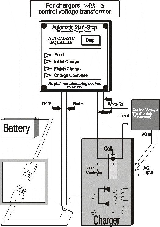
1 MCC Automatic Start-Stop Microcomputer Charger Control Installation & Operation Instructions Warning: Read ALL the instructions before starting. If anything is not clear, call your dealer or contact Arrgh!! 1. Check that the charger is operating properly. 2. Before doing any work, ensure that: AC power to the charger is OFF. Charger is NOT connected to a battery. Charger IS grounded. Installation 3. If the charger draws more than 10 amps, IT MUST HAVE A LINE CONTACTOR. If the charger s input voltage is greater than 480 vac, IT MUST HAVE A CONTROL VOLTAGE TRANSFORMER to lower the voltage to the line contactor s coil. Install these, if necessary. 4. Mount the MCC on any convenient, flat surface on the front of the charger. Drill two holes using the supplied template. Route the wires to the interior of the charger. 5. Connect the four MCC wires. Background: The MCC is powered by dc from the battery via two battery sense wires. The MCC s microprocessor controls the operation of an internal relay. This relay, via two white control wires, functions as an on/off switch for the charger s line contactor. The contactor, in turn, starts and stops the charger. Battery Sense Wires: Connect the MCC s RED and BLACK wires to the charger s output cables: the RED wire to positive, the BLACK wire to negative. Line Contactor Control Wires: Locate the two wires from the line contactor s coil to the existing timer or control. Remove them from the timer or control and connect them to the MCC s two WHITE wires. Do NOT connect the MCC s white wires to the wires that power the timer motor. You will damage the MCC s internal relay contacts.
2 6. PROGRAM OPTIONS: Inside the MCC is a red or white, ten position rotary switch. This switch selects several program options. Choose the option you want. POSITION "O": NORMAL. This position is for normal, no-delay charging. All MCCs ARE FACTORY SET AT THIS POSITION. Minimum charge time is 60 minutes. POSITIONS "1-6": DELAYED START. These positions provide for a delayed start of 1 to 6 hours in one-hour increments. They delay charging while the battery cools down, permit charging during off-peak hours (saving on the cost of KWHs), and can prevent boost charging (which may shorten battery life). Minimum charge time is 60 minutes. POSITION "7": OPPORTUNITY CHARGING. This position is for light duty or intermittent applications, such as airline baggage handling, where the battery is only partially discharged before recharging. Minimum charge time is 10 minutes. POSITION "8": MAINTENANCE CHARGING. This position is useful during plant shutdown or when the battery is left unused for long periods of time. If the battery s voltage drops to 80% of full charge, the charger turns on and returns it to full charge. Minimum charge time is 20 minutes. POSITION "9": TEST / CALIBRATION. This position is for factory testing and calibration. 7. Check and verify ALL connections before applying power or connecting a battery. 8. Turn on the ac power, then connect a battery. 1. After a 3-second delay, the MCC s INITIAL CHARGE light should come on "steady" and the charger should start. (Note: If a delayed start is set, the INITIAL CHARGE light will "flash". Press the STOP button to override the delay and start the charger). 2. Wait 13 seconds. Press the STOP button: the charger should turn off. If the charger does not turn off, turn the ac power off, remove the MCC s cover and check that the cover s flexible tail is connected firmly to its socket on the MCC s circuit board. Turn the ac power back on and press the STOP button again. 3. Disconnect, then reconnect the battery to reset the MCC. 4. MANUAL EQUALIZE MODEL ONLY (automatic equalize models ignore this step). Press the EQUALIZE button. The adjacent LED should light indicating that this function has been selected. Press the EQUALIZE button again to cancel. 9. With the charger started again for one (1) minute. 1. Disconnect the battery WITHOUT pressing the STOP button. Most chargers will turn off; a few chargers with highly regulated outputs will not turn off. 2. If your charger does not turn off and "if" this will cause a problem (note: the charger can still be turned off by pressing the STOP button), carry out step "3". 3. Push the STOP button and turn the charger off. Remove the MCC s cover and cut the jumper trace marked "J1" located on the circuit board near the ten position rotary switch. The charger should now turn off if the battery is disconnected in mid-charge. Try it.
3 Note: With the jumper cut, the MCC will NOT restart the charger after a power outage. 10. That s it. Installation is now complete! Note: MCCs are calibrated for 10 feet (3 meters) of charger output cable and battery cable combined. For longer cables, consult your dealer or Arrgh!!. For additional savings, use Arrgh!! s low voltage controls for battery- powered vehicles, and hydrogen gas detectors for charging room safety.
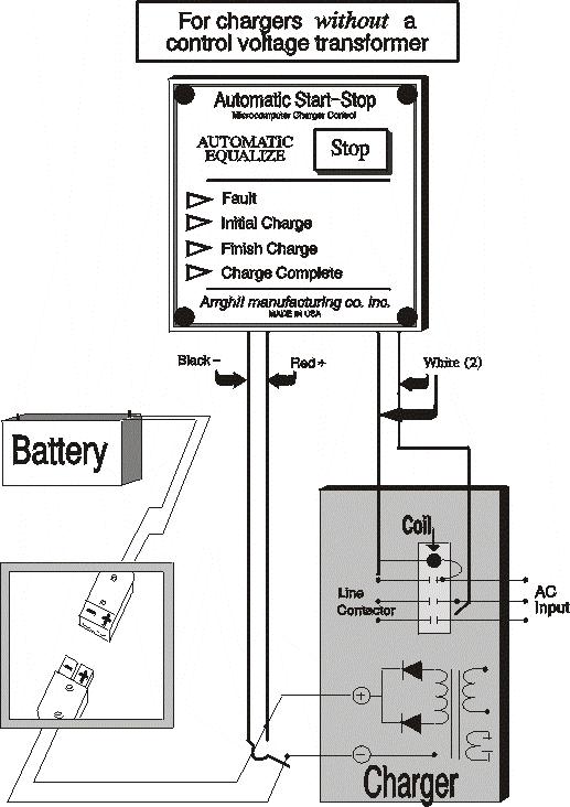
4 Installation Diagrams
5
6 Operation Chart
7 If the battery voltage is low due to over-discharge or to an internal battery problem, there may be insufficient voltage to close the MCC s internal relay to activate the charger s line contactor even though the INITIAL CHARGE light is on. The minimum voltage required is approximately 1.4 volts per cell.
IV. PROOF OF PURCHASE: A warranty claim must be accompanied by proof of the date of purchase.
 PD9100 / 9200 SERIES POWER CONVERTER OWNERS MANUAL PROGRESSIVE DYNAMICS, INC. POWER CONVERTER LIMITED WARRANTY I. LIMITED WARRANTY: Progressive Dynamics, Inc. warrants its power converter to be free from
C.E. Niehoff & Co. C653/C653A and C625 Alternators Troubleshooting Guide NOTICE. Hazard Definitions. Battery Charge Volt and Amp Values
 C.E. Niehoff & Co. C653/C653A and C625 Alternators Troubleshooting Guide Hazard Definitions These terms are used to bring attention to presence of hazards of various risk levels or to important information
N1387 Series Troubleshooting Guide for N Alternators
 N1387 Series Troubleshooting Guide for N1387-1 Alternators Hazard Definitions These terms are used to bring attention to presence of hazards of various risk levels or to important information concerning
C802/C802D/C802TD/C820 Alternators Troubleshooting Guide
 C802/C802D/C802TD/C820 Alternators Troubleshooting Guide Hazard Definitions These terms are used to bring attention to presence of hazards of various risk levels or to important information concerning
Auto-Trol Limited 1660 SW 196th Avenue * Aloha, OR 97003
 Auto-Trol Limited 1660 SW 196th Avenue * Aloha, OR 97003 Model AT-1000 Installation Instructions The model AT-1000 Auto-Trol Battery Charger Control extends battery life reduces maintenance power by replacing
HYDRUS INSTALLATION INSTRUCTION P/N: 3801-EOP AUTO REVERSE / AUTO STOP OPTION KIT FOR HYDRUS 2000 MAIN PANEL
 HYDRUS INSTALLATION INSTRUCTION P/N: 3801-EOP AUTO REVERSE / AUTO STOP OPTION KIT FOR HYDRUS 2000 MAIN PANEL BILL OF MATERIALS: (1) P/N: 4372 - LATCHING RELAY, (1) P/N: 5322 RELAY SOCKET, (4) P/N: 3700-74
Valcom Failsafe Unit. 1620ESv2 SERIES. Operation and Maintenance Manual
 Valcom Failsafe Unit 1620ESv2 SERIES Operation and Maintenance Manual Table of Contents Section Title Page 1. - Introduction.. 2. - Unpacking the Failsafe unit. 3. - Installation 3.1 - Auto / Timed UPS
C.E. Niehoff & Co. N1601, N1602, N1603, and N1604 Alternator Troubleshooting Guide NOTICE. Hazard Definitions. Battery Charge Volt and Amp Values
 C.E. Niehoff & Co. N1601, N1602, N1603, and N1604 Alternator Troubleshooting Guide Hazard Definitions These terms are used to bring attention to presence of hazard(s) of various risk levels or to important
APOLLO Gate Operators, Inc.
 APOLLO Gate Operators, Inc. Model BA12 12 VOLT DC BARRIER ARM OPERATOR INSTALLATION MANUAL 0707 CONTENTS IMPORTANT SAFETY INSTRUCTIONS... 3 Applications... 4 Pre-Installation Checklist... 5 Operator Installation...
Troubleshooting Guide for N1225-1/N1237-1/N Alternators
 Troubleshooting Guide for N1225-1/N1237-1/N1505-1 Alternators Hazard Definitions These terms are used to bring attention to presence of hazards of various risk levels or to important information concerning
600 Series Troubleshooting Guide for C651 and C654 Alternators
 600 Series Troubleshooting Guide for C651 and C654 Alternators Hazard Definitions These terms are used to bring attention to presence of hazards of various risk levels or to important information concerning
ATD-5928 RECHARGEABLE 12 VOLT 22 AMP/HOUR JUMP START OWNERS MANUAL
 ATD-5928 RECHARGEABLE 12 VOLT 22 AMP/HOUR JUMP START OWNERS MANUAL 1700 PEAK AMPS/700 CRANKING AMPS OF STARTING POWER. STARTS CARS, TRUCKS, RV s AND BOATS WITHOUT THE NEED OF ANOTHER VEHICLE OR AC POWER
FlexCharger Battery Chargers
 FlexCharger Battery Chargers Operating Instructions Definitions (as used in these instructions) Flooded Battery Lead-acid battery with liquid electrolyte that requires open-venting and regular water replacement.
Application Engineering
 Application Engineering February, 2009 Copeland Digital Compressor Controller Introduction The Digital Compressor Controller is the electronics interface between the Copeland Scroll Digital Compressor
MD10. Engine Controller. Installation and User Manual for the MD10 Engine Controller. Full Version
 MD10 Engine Controller Installation and User Manual for the MD10 Engine Controller. Full Version File: MartinMD10rev1.4.doc May 16, 2002 2 READ MANUAL BEFORE INSTALLING UNIT Receipt of shipment and warranty
ATD-5925 RECHARGEABLE 12 VOLT 18 AMP/HOUR JUMP START WITH BUILT-IN 260 PSI AIR COMPRESSOR OWNERS MANUAL
 ATD-5925 RECHARGEABLE 12 VOLT 18 AMP/HOUR JUMP START WITH BUILT-IN 260 PSI AIR COMPRESSOR OWNERS MANUAL 1000 PEAK AMPS/400 CRANKING AMPS OF STARTING POWER. STARTS CARS, TRUCKS, RV s AND BOATS WITHOUT THE
SERVICES INDUSTRIELS SAVARIA INC. OWNER S MANUAL BATTERY OPERATED B.07 G
 SERVICES INDUSTRIELS SAVARIA INC. BATTERY OPERATED B.07 G OWNER S MANUAL 04-2003 -5- Thank you for purchasing a Savaria product. The Savaria team hopes you will enjoy your new B.07 stairlift. If you have
Applied Energy SOlutions
 Applied Energy SOlutions Made in the U.S.A. Family of products THE POWER OF EXCELLENCE One Technology Place Caledonia, New York 14423 Tel: 585-538-4421 800-836-2132 Fax: 585-538-6345 Web: www.appliedenergysol.com
6500DC Dual Motor Wireless Controller Kits
 6500DC Dual Motor Wireless Controller Kits READ ALL DIRECTIONS FIRST BEFORE PROCEEDING NOTE: SEE THE QUICK PROGRAM INSTRUCTIONS BEFORE OPERATING THE FIRST TIME. DO NOT REMOVE THE TRANSMITTER BATTERY Please
HP21 SERVICE SUPPLEMENT UNIT INFORMATION. TSC6 Two-Speed Control
 SERVICE UNIT INFORMATION SUPPLEMENT HP21 Corp. 9426 L10 Litho U.S.A. All HP21-4 and -5 units (single and three phase) are equipped with a TSC6 two-speed control. The TSC6 (A14) two-speed control contains
ECU. Speed Switch Manual. Contents. ECU is a registered trademark of Engineering Concepts Unlimited Inc.
 ECU Speed Switch Manual Contents ECU is a registered trademark of Engineering Concepts Unlimited Inc. Contents Unit review Magnetic pickup example AC input example Design Guide Troubleshooting guide 24
ATD-5921 RECHARGEABLE 12 VOLT 18 AMP/HOUR JUMP START OWNERS MANUAL
 ATD-5921 RECHARGEABLE 12 VOLT 18 AMP/HOUR JUMP START OWNERS MANUAL 900 PEAK AMPS/400 CRANKING AMPS OF STARTING POWER. STARTS CARS, TRUCKS, RV s AND BOATS WITHOUT THE NEED OF ANOTHER VEHICLE OR AC POWER
Application Engineering
 Application Engineering March 2011 Copeland Digital Compressor Controller Introduction The Digital Compressor Controller is the electronics interface between the Copeland Scroll Digital compressor or the
APOLLO Gate Operators, Inc.
 APOLLO Gate Operators, Inc. Model 3500ETL/3600ETL Commercial Swing Gate Operator INSTALLATION MANUAL 01/08 CONTENTS IMPORTANT SAFETY INSTRUCTIONS. 3 Applications... 4 Pre-Installation Checklist... 5 Parts
PFC W HF/PFC Battery Charger
 PFC 5000 5000W HF/PFC Battery Charger Description Advanced high frequency switching design with 92% typical efficiency Fully sealed enclosure providing improved reliability in demanding environments >
EV Power - A-Series 8 Cell, 16 Cell and 24Cell Chargers Installation & Usage Instructions.
 A-CHARGERS MANUAL 1.1 EV Power - A-Series 8 Cell, 16 Cell and 24Cell Chargers Installation & Usage Instructions. A-Series Charger Features - Simple to install and use, microprocessor control. - LiFePO4
Power Distribution System User s Manual. Model: PDS-100
 Power Distribution System User s Manual Model: PDS-0 Section Page Product Overview... 1 I) General Information... 2 II) Important Safety Information... 2 III) Installation... 3 A) Materials Provided...
Service Manual for Battery Control Center
 Service Manual for Battery Control Center P/N 82 E0071 00 (Ref. 81 1317) June, 1999 Battery Control Box Operation Charging Circuit This function charges the coach battery from the engine alternator while
model ps600 Address all communications and shipments to: FEDERAL SIGNAL CORPORATION
 MODEL: PS600 HZ: 60 A model ps600 installation and service manual for federal model ps600 FEDERAL SIGNAL CORPORATION POWER SUPPLY VOLTS: SERIES: 120VAC FEDERAL SIGNAL CORPORATION UNIVERSITY PARK, IL. U.S.A.
HP10134 & HP10135 KITS BASIC SIMULTANEOUS AIR SPRING ACTIVATION KIT
 HP10134 & HP10135 KITS BASIC SIMULTANEOUS AIR SPRING ACTIVATION KIT Thank you and congratulations on the purchase of a Pacbrake simultaneous air spring activation kit. This kit was designed to add in-cab
CONGRATULATIONS ON YOUR PURCHASE OF YOUR THUNDER SOLAR REGULATOR!
 CONGRATULATIONS ON YOUR PURCHASE OF YOUR THUNDER SOLAR REGULATOR! For your personal safety read, understand and follow the information provided in this instruction manual and on the solar regulator. 1
IRRIGATION 810-3T-PLUS TRANSMITTER GUIDE
 IRRIGATION 810-3T-PLUS TRANSMITTER GUIDE Pg. 2 HOT SHOT OVERVIEW 3 STANDARD OPERATION MODE 4 HOW TO CONTROL AND SHARE MULTIPLE S 5 TRANSMITTER FUNCTION SWITCH SETTINGS 6 OPERATING THE TEST BEACON 7 OPERATING
! WARNING To avoid risk of electrical shock, personal injury or death; disconnect power to oven before servicing, unless testing requires power.
 Technical Information Double Oven Electric Range MER6555AAB/Q/W MER6751AAB/Q/S/W MER6755AAB/Q/S/W MER6775AAB/F/N/Q/S/W Due to possibility of personal injury or property damage, always contact an authorized
SERVICE MANUAL (DOMESTIC & INTERNATIONAL)
") SERVICE MANUAL (DOMESTIC & INTERNATIONAL) DUAL TECHNOLOGY FINISHER MODEL 1960 & 1980 SERIES Lincoln Foodservice Products, LLC 1111 North Hadley Road Fort Wayne, Indiana 46804 United States of America Telephone:
SERVICE MANUAL (DOMESTIC & INTERNATIONAL) DUAL TECHNOLOGY FINISHER MODEL 1960 & 1980 SERIES Lincoln Foodservice Products, LLC 1111 North Hadley Road Fort Wayne, Indiana 46804 United States of America Telephone:
MODEL ELC-12/40-CVM-D BATTERY CHARGER
 NATIONAL RAILWAY SUPPLY MODEL ELC-12/40-CVM-D BATTERY CHARGER Installing, Operating and Service Instructions for the ELC-12/40-CVM-D Solid State Charger PLEASE SAVE THESE IMPORTANT SAFETY AND OPERATING
N1233 Series Troubleshooting Guide for N Alternator
 N1233 Series Troubleshooting Guide for N1233-2 Alternator Hazard Definitions These terms are used to bring attention to presence of hazards of various risk levels or to important information concerning
TROUBLESHOOTING GENERATOR UNITS
 TROUBLESHOOTING GENERATOR UNITS Figure 3.17 Troubleshooting Flow Chart For Direct Excited (Brush Type) Generators or later. 68 Troubleshooting Direct Excited (Brush Type) Generators Refer to Figure 3.17
HYPPOETL HYPPO DUALETL 12 VOLT DC Swing Gate Operator
 HYPPOETL HYPPO DUALETL 12 VOLT DC Swing Gate Operator Manufactured by NICE SpA INSTALLATION MANUAL 08/10 CONTENTS IMPORTANT SAFETY INSTRUCTIONS... 3 Applications...... 4 Pre-Installation Checklist... 5
Optional: Wiring a Relay for Gauge Controlled Output
 Wiring Installation Instructions for : PYROMETER 2 1/16 Spek Pro Professional Racing Gauge GAUGE 12-Pin Wiring Harness & Plug Firewall Grommet DIAGRAM 1 Black-Engine Ground 12-Pin Wiring Harness CUP Coil
IMPORTANT SAFEGUARDS READ THIS MANUAL AND FOLLOW ALL SAFETY INSTRUCTIONS THOROUGHLY BEFORE OPERATING THE EMIU INVERTER SYSTEM SAVE THESE INSTRUCTIONS
 THIS UNIT CONTAINS A RECHARGEABLE VALVE-REGULATED LEAD ACID BATTERY. PLEASE RECYCLE OR DISPOSE OF PROPERLY. IMPORTANT SAFEGUARDS INTERRUPTIBLE EMERGENCY LIGHTING UNIT INVERTER INSTRUCTION MANUAL When using
SOLAR LIGHTING CONTROLLER SUNLIGHT MODELS INCLUDED IN THIS MANUAL SL-10 SL-10-24V SL-20 SL-20-24V
 SOLAR LIGHTING CONTROLLER OPERATOR S MANUAL SUNLIGHT MODELS INCLUDED IN THIS MANUAL SL-10 SL-10-24V SL-20 SL-20-24V 10A / 12V 10A / 24V 20A / 12V 20A / 24V 1098 Washington Crossing Road Washington Crossing,
N1240/N1243 Series Troubleshooting Guide for N1240-3/N Alternators
 N1240/N1243 Series Troubleshooting Guide for N1240-3/N1243-2 Alternators Hazard Definitions These terms are used to bring attention to presence of hazards of various risk levels or to important information
! WARNING To avoid risk of electrical shock, personal injury or death; disconnect power to oven before servicing, unless testing requires power.
 Technical Information Double Oven Electric Range MER6549BAQ/W MER6769BAQ/W Due to possibility of personal injury or property damage, always contact an authorized technician to service or repair this unit.
MBCM-24 MULTIPLE BATTERY CHARGING MODULE (FOR MARINE APPLICATIONS) FEATURES SPECIFICATIONS APPLICATIONS DESCRIPTION & OPERATION ORDERING INFORMATION
 FEATURES SPECIFICATIONS APPLICATIONS DESCRIPTION & OPERATION ORDERING INFORMATION") FEATURES Extends the trolling motor run time by charging the trolling motor batteries each time the boat s main engine is used. Automatically senses engine s alternator charge voltage, connects trolling
FEATURES Extends the trolling motor run time by charging the trolling motor batteries each time the boat s main engine is used. Automatically senses engine s alternator charge voltage, connects trolling
DANGER. What s in the BOX. N02 Introduction. Before Started
 EN DANGER. Prior to use, please read and understand product Safety information. Failure to follow the instructions may result in ELECTRICAL SHOCK, EXPLOSION, or FIRE, which may result in serious INJURY,
Modulating Furnace Information. Warning on Meter Setting - Read First!
 Modulating Furnace Information Pressure Transducer Pressure DC Volts 0.00" 0.25 0.20" 0.63 0.25" 0.72 0.30" 0.82 0.35" 0.91 0.40" 1.00 0.45" 1.09 0.50" 1.19 0.55" 1.28 0.60" 1.38 0.65" 1.47 0.70" 1.56
ITS-50R TRANSFER SWITCH OWNER S MANUAL
 ITS-50R OWNER S MANUAL IOTA Engineering Transfer Switches provide automatic power switching between two or three separate 120/240 volt AC input sources, including powercords, onboard generators, onboard
INSTALLATION MANUAL & OPERATING INSTRUCTIONS
 INSTALLATION MANUAL & OPERATING INSTRUCTIONS SIGALARM MODEL 210 PMB 405; West SR 46 Sanford, FL 32771 (800) 589-3769 (407) 328-9479 Fax: (407) 328-5889 Email:info@sigalarminc.com Internet: http://www.sigalarminc.com
5 IN 1 JUMP START OPERATION & MAINTENANCE INSTRUCTIONS MODEL NO: JS5IN1 PART NO: LS0810
 5 IN 1 JUMP START MODEL NO: JS5IN1 PART NO: 6240005 OPERATION & MAINTENANCE INSTRUCTIONS LS0810 INTRODUCTION Thank you for purchasing this CLARKE product. Before attempting to use this product, please
PROFESSIONAL INSTALLATION STRONGLY RECOMMENDED
 Installation Instructions CPL Master Module PROFESSIONAL INSTALLATION STRONGLY RECOMMENDED Installation Precautions: Roll down window to avoid locking keys in vehicle during installation Avoid mounting
Installation and Maintenance Instructions. World Leader in Modular Torque Limiters. PTM-4 Load Monitor
 World Leader in Modular Torque Limiters Installation and Maintenance Instructions PTM-4 Load Monitor 1304 Twin Oaks Street Wichita Falls, Texas 76302 (940) 723-7800 Fax: (940) 723-7888 E-mail: sales@brunelcorp.com
i n s t r u c t i o n m a n u a l
 i n s t r u c t i o n m a n u a l 8006 Six-Station AC Timer Residential/Light Commercial Independent Program Irrigation Controllers Installation, Programming and Operating Instructions Features Operates
Heat Tracing Sales Mt. Airy, Maryland Controls
 Heat Tracing Line Sensing Control Panels Solid State Relay Output Rated 30 Amps or Two-Pole Contactor Control Output Universal Inputs NEMA 4/4X Enclosure Ground Fault Alarm/Trip Monitor or GFI Circuit
! WARNING To avoid risk of electrical shock, personal injury, or death, disconnect power to range before servicing, unless testing requires power.
 Electric Freestanding Range Technical Information AER5712BA* MER5751BA* MER5752BA* MERH752BA* MERM752BA* Due to possibility of personal injury or property damage, always contact an authorized technician
MODEL ELC-12/60-D BATTERY CHARGER
 *32198* NATIONAL RAILWAY SUPPLY Installing, Operating and Service Instructions for the 12/60 Solid State Charger MODEL ELC-12/60-D BATTERY CHARGER PLEASE SAVE THESE IMPORTANT SAFETY AND OPERATING INSTRUCTIONS
BATTERY STARTER/CHARGER MODEL NO: BC125, BC190
 BATTERY STARTER/CHARGER MODEL NO: BC125, BC190 PART NO: 6210125, 6210200 OPERATION & MAINTENANCE INSTRUCTIONS LS0616 INTRODUCTION Thank you for purchasing this CLARKE Battery starter / charger Please read
Section 03: Installation Procedures
 Section 03: Installation Procedures Machine Installation & Hook-Up! IMPORTANT Before beginning the Machine Installation & Hook-Up it is important to review the entire Pre-Installation section. Unpacking
INSTALLATION MANUAL. Model: PLUS Vehicle Security
 R Vehicle Security INSTALLATION MANUAL Model: PLUS-5000 Copyright 1999 Magnadyne Corporation For Technical Assistance (800) 638-3600 For Fax on Demand Technical Assistance (800) 994-9977 (Must be a Registered
Invertek. Battery Management Control System DC-SW-140 & DC-SW-140C DC-SW-70 & DC-SW-70C USER MANUAL
 利佳興業股份有限公司 RICH ELECTRIC CO.,LTD. Invertek Battery Management Control System DC-SW-140 & DC-SW-140C DC-SW-70 & DC-SW-70C USER MANUAL Rich Electric Co. DC-SW Battery Management Control System User Manual
Do isolate the power supply from other high power systems such as Stereos and Alarms
 Thank you for purchasing a Smart Ride Air Management System, AIRBAGIT.COM s premier flagship product. This system will meet all of your custom and utility needs and will provide you years of trouble free
15 N ONE Multi-Purpose Vehicle Jumpstart System
 15 N ONE Multi-Purpose Vehicle Jumpstart System Double Injection Casing with Rubberized Protective Bumper Guards 400 Watt Continuous 800 Watt Peak Inverter With two 110 V AC Outlets Two Detachable LED
VC-4820 Programmable DC-DC Converter with Battery Charger function USER'S MANUAL
 1. INTRODUCTION VC-4820 Programmable DC-DC Converter with Battery Charger function USER'S MANUAL This MCU controlled Step Down DC-DC Converter has a digitally adjustable output in 0.2V increments. This
! WARNING To avoid risk of electrical shock, personal injury or death; disconnect power to oven before servicing, unless testing requires it.
 Electric Wall Oven Technical Information AEW3630DD*, AEW4630DD*, JJW8230DD* MEW5627DD*, MEW5630DD*, MEW6627DD*, MEW6630DD*, Refer to Service Manual 6022506 for detailed installation, operating, testing,
Series BFM Bulk Flow Monitor 1A FUSE RED LED RELAY. Part Number BFM-1 BFM-2 BFM-3 BFS-1
 Series Bulk Flow Monitor Specifications - Installation and Operating Instructions Bulletin FL-1-4x 3/4 CONDUIT KNOCKOUTS BFS 1A FUSE RED LED RELAY 5-9/64 [130.45] TRANSFORMER 3[76.20] GREEN LED 7 [177.80]
FAN-STOP INSTRUCTION MANUAL
 Form 1289 FAN-STOP INSTRUCTION MANUAL IMPORTANT Read these instructions fully BEFORE INSTALLING. Equipment damage and personal injury may result from improper installation and/or use. 1. Instructions 1.
FOR New Electric Kit and Remote Control Installation
 Installation Manual COMMAND-10 REMOTE AND COMMAND STATION FOR New Electric Kit and Remote Control Installation Use these in place of the rocker switch and solenoid section of instructions in your roll
User s Manual. Automatic Switch-Mode Battery Charger
 User s Manual Automatic Switch-Mode Battery Charger IMPORTANT Read, understand, and follow these safety rules and operating instructions before using this battery charger. Only authorized and trained service
Covers All 430, 440, 441 and CJ Series Advanced Security Systems.
 INSTALL GUIDE Covers All 430, 440, 441 and CJ Series Advanced Security Systems www.ultrastarters.com Technical Support: 866-698-5872 ext 0 support@ultrastarters.com FCC/ID Notice This device complies with
To ensure proper installation, digital pictures with contact information to before startup.
 Check List for Optimal Filter Performance [ ] There should be no back-pressure on the flush line. A 1 valve should have a 2 waste line, and 2 valve should have a 3 waste line. Do not use rubber hosing
ES52 Auto Start Engine Controller Installation and User Manual for the ES52 Auto Start Engine Controller.
 ES52 Auto Start Engine Controller Installation and User Manual for the ES52 Auto Start Engine Controller. Full Version File: ES52rev2.63.doc October 24, 2006 2 Thank You For Purchasing This DynaGen Product
RK Standby Battery Operator s Manual
 49-8104RK Standby Battery Operator s Manual Part Number: 71-0118RK Revision: C Released: 8/4/17 www.rkiinstruments.com Product Warranty RKI Instruments, Inc. warrants gas alarm equipment sold by us to
PHEV Conversion Kit User Manual
 PHEV Conversion Kit User Manual for 2010 Prius Warning: You are strongly recommended to have a specialist to undertake this installation! High Voltage (HV) Direct Current (DC) Warning: Traction battery
R & D SPECIALTIES ROTROL I USER'S MANUAL
 R & D SPECIALTIES ROTROL I USER'S MANUAL TABLE OF CONTENTS INTRODUCTION...2 SPECIFICATIONS...2 CONTROLS AND INDICATORS...3 TIME DELAYS...4 INSTALLATION...5 SYSTEM OPERATION...9 TROUBLESHOOTING...13 OPTIONAL
B-PC20 Power Close Module
 B-PC20 Power Close Module Instruction Manual Document number: B-PC20-C Release: V1.2 Date: OCT 12,2011 ! WARNING This control must be adjusted/serviced by a qualified person. The service technician must
PHEV Conversion Kit User Manual
 PHEV Conversion Kit User Manual for 2003-2009 Prius Warning: You are strongly recommended to have a specialist to undertake this installation! High Voltage (HV) Direct Current (DC) Warning: Traction battery
Advanced Troubleshooting Guide Snorkel V Battery Charger Rev 0 3JAN07
 Advanced Troubleshooting Guide Snorkel 3050097 24V Battery Charger Rev 0 3JAN07 1. How It Works: The 3050097 charger converts AC voltage to DC voltage, then uses high frequency to re-convert it to DC voltage/current
IMPORTANT SAFEGUARDS READ THIS MANUAL AND FOLLOW ALL SAFETY INSTRUCTIONS THOROUGHLY BEFORE OPERATING THE LMIU INVERTER SYSTEM SAVE THESE INSTRUCTIONS
 THIS UNIT CONTAINS A RECHARGEABLE VALVE-REGULATED LEAD ACID BATTERY. PLEASE RECYCLE OR DISPOSE OF PROPERLY. IMPORTANT SAFEGUARDS INTERRUPTIBLE EMERGENCY LIGHTING UNIT INVERTER INSTRUCTION MANUAL When using
Cross Hare Installation Guide
 Cross Hare Installation Guide Introduction: The Cross Hare is designed to provide all of the functions you need to control a one or two track grade crossing in a prototypical manner. The Cross Hare uses
! WARNING To avoid risk of electrical shock, personal injury or death; disconnect power to oven before servicing, unless testing requires power.
 Technical Information Double Oven Dual Fuel Range JDR8895AAB/S/W Due to possibility of personal injury or property damage, always contact an authorized technician for servicing or repair of this unit.
ODYR-25-1 & SLX-25-1 rev. A VACUUM/BOOST PRESSURE, TEMP, and EGT GAUGE
 ODYR-25-1 & SLX-25-1 rev. A VACUUM/BOOST PRESSURE, TEMP, and EGT GAUGE SENSOR CONNECTION: The vac./boost sensor has 1/8 NPT on the end which can be treaded into the intake track, or into a pipe adapter
EMIU 720W Mini Inverter
 THIS UNIT CONTAINS A RECHARGEABLE VALVE-REGULATED LEAD ACID BATTERY. PLEASE RECYCLE OR DISPOSE OF PROPERLY. INTERRUPTIBLE EMERGENCY LIGHTING UNIT INVERTER INSTRUCTION MANUAL IMPORTANT SAFEGUARDS When using
500 Series Troubleshooting Guide for C520 Alternators
 500 Series Troubleshooting Guide for C520 Alternators Hazard Definitions These terms are used to bring attention to presence of hazards of various risk levels or to important information concerning product
QuickBoost Instruction Manual
 Sheet 1 of 12 QuickBoost Instruction Manual MobilePower, LLC. Bluffton, SC 29910 www. Mobilepower-us.com Office: (800) 708-8550 support@mobilepower-us.com customerservice@mobilepower-us.com Sheet 2 of
Stir-Guard Operation. Instructions Design III Stir-Guard Option
 1004 East Illinois Street Assumption, IL 62510 1-217-226-4421 Stir-Guard Operation Instructions Design III Stir-Guard Option The Stir-Guard is designed to protect the grain by shutting off the Stir-Ator
Self-Testing Industrial Series
 Series: AS-I (Maint.-Free) Self-Testing Industrial Series Emergency Lighting Equipment Instructions for INSTALLATION OPERATION SERVICE SPECIFICATIONS 1300650 1300654 1300666 1300754 1300823 1300886 Hubbell
Installation Instructions
 SOLAR GARDEN POWER CELL SKU#229120 Rated Voltage 12VDC Thank you for purchasing this quality Lucci product. To ensure correct function and safety, please read and follow all instructions carefully before
Quick Start Guide TS 910
 Quick Start Guide TS 910 DANGER HAZARD OF ELECTRICAL SHOCK, EXPLOSION, OR ARC FLASH Read and understand this quick start guide before installing and operating the transfer switch The installer is responsible
Installation and Operating Instructions
 PUMP PROTECTION SYSTEM Installation and Operating Instructions Congratulations on your purchase of a Franklin Electric pump protection system. Pumptec-Plus is the most sophisticated pump protection system
C.E. Niehoff & Co. C703/C703A and C706 Alternators Troubleshooting Guide CAUTION. Testing Guidelines. Hazard Definitions WARNING.
 C.E. Niehoff & Co. C703/C703A and C706 Alternators Troubleshooting Guide WARNING Before troubleshooting any CEN products, the service technician should: read, understand, and agree to follow all information
SERIES 700/700E FACTORY KEYLESS UPGRADE INSTALLATION MANUAL
 SERIES 700/700E FACTORY KEYLESS UPGRADE INSTALLATION MANUAL Items Supplied with the System: Installation Instructions: Main unit 1. Mounting the module: Plug In LED Mount the module in a suitable location
MODEL 520 REMOTE START ENGINE MANAGEMENT SYSTEM
 MODEL 520 REMOTE START ENGINE MANAGEMENT SYSTEM DSE 520 ISSUE 4 4/4/02 MR 1 TABLE OF CONTENTS Section Page INTRODUCTION... 4 CLARIFICATION OF NOTATION USED WITHIN THIS PUBLICATION.... 4 1. OPERATION...
INSTALLATION INSTRUCTIONS FOR SYMCOM'S MODEL 777-HVR-SP ELECTRONIC OVERLOAD RELAY
 CONNECTIONS INSTALLATION INSTRUCTIONS FOR SYMCOM'S MODEL 777-HVR-SP ELECTRONIC OVERLOAD RELAY BE SURE POWER IS DISCONNECTED PRIOR TO INSTALLATION!! FOLLOW NATIONAL, STATE AND LOCAL CODES! READ THESE INSTRUCTIONS
Field Commander Lite Wiring Manual
 2014-17 Field Commander Lite Wiring Manual (New Large Style Board board label Comm6 FC V4.1 or V4.2 only 1 relay ) Section 1 Pages 2-6 Irrigation Pivot wiring. Section 2 Page 6 Simple on/off monitor only
LINE INTERACTIVE LONG BACKUP TIME UPS EN-1000 / EN-2000 USER S MANUAL
 LINE INTERACTIVE LONG BACKUP TIME UPS EN-1000 / EN-2000 USER S MANUAL Important Safety Information Before installing UPS EN-1000/ EN-2000, please read the operating instructions carefully. Special attention
FEATURES. Power Status and Charge Indicator: A red LED indicates the battery is charging and a green LED indicates the battery is fully charged.
 7-in-1 Power Station Model: 52036 DO NOT RETURN TO STORE. Please CALL 800-348-5004 for parts and service. CALIFORNIA PROPOSITION 65 WARNING: You can create dust when you cut, sand, drill or grind materials
RK Standby Battery Operator s Manual
 49-8103RK Standby Battery Operator s Manual Part Number: 71-0117RK Revision: 0 Released: 8/18/08 www.rkiinstruments.com Product Warranty RKI Instruments, Inc., warrants gas alarm equipment sold by us to
HP10098 BASIC INDEPENDENT AIR SPRING ACTIVATION KIT
 HP10098 BASIC INDEPENDENT AIR SPRING ACTIVATION KIT Thank you and congratulations on the purchase of a Pacbrake basic independent air spring activation kit. Please read the entire installation manual prior
EAGLETRON II REMOTE CONTROL OPERATOR and MAINTENANCE. Remote Control Procedure
 EAGLETRON II REMOTE CONTROL OPERATOR and MAINTENANCE Remote Control Procedure WARNING! DO NOT OPERATE REMOTE CONTROL UNLESS YOU HAVE A CLEAR VIEW OF THE REAR OF THE TRAILER. WARNING! THE OPERATOR IS REQUIRED
Visit our web site at AMR LS-3000, LS-3010 & LS-3020 BELT SLIP/SEQUENCE CONTROL INSTALLATION AND SETUP INSTRUCTIONS
 AMR INC. DESIGN & MANUFACTURING FOR MINING WORLDWIDE P.O. BOX 234, ROCKY GAP, VA 24366 PHONE (276)928-1712 FAX (276)928-1814 Email sales@americanmineresearch.com Visit our web site at www.americanmineresearch.com
Document: PRODSPEC-140 Revision: G DCN No Date: October 1, 2014 Product: 10-amp EnerGenius NRG Battery Charger
 Document: PRODSPEC-140 Revision: G DCN No. 106512 Date: October 1, 2014 Product: 10-amp EnerGenius NRG Battery Charger 1. GENERAL DESCRIPTION 1.1 General Description Fully regulated, constant voltage,