Installation & Operation Manual 180W: 12V, 10A; 24V, 6A 300W: 12V, 12A; 24V, 10A 450W: 12/24V, 15A
|
|
|
- Tyrone Reeves
- 5 years ago
- Views:
Transcription
, Monday through Friday, or visit our website.")
1 Genset, Marine & Stationary Battery Charger Installation & Operation Manual 180W: 12V, 10A; 24V, 6A 300W: 12V, 12A; 24V, 10A 450W: 12/24V, 15A SENS Part Number: Document Revision: K DCN Number: Date: April 17, 2018 PATENTED US 9,270,140; 9,385,556; 9,413,186; 9,509,164; 9,466,995; 9,948,125 Installation or service questions? Call SENS between 8 a.m. and 5 p.m. (Mountain Time), Monday through Friday, or visit our website Industrial Circle Longmont, CO Phone: Fax: service@sens-usa.com Web: Copyright Stored Energy Systems LLC 2017 The SENS name / logo, MicroGenius, HELIX, and Dynamic Boost are trademarks of Stored Energy Systems LLC 1
2 TABLE OF CONTENTS 1 IMPORTANT SAFETY INSTRUCTIONS MODEL NUMBER BREAKOUT PERFORMANCE SPECIFICATIONS SYSTEM OVERVIEW MOUNTING INSTRUCTIONS Mounting Location Mounting Instructions CHARGER SETUP Factory Jumper Configuration Standard Jumper Configuration Keypad Configuration Optional Ultracapacitor Mode Setup Program Mode Load Share Charger Setup SAE J1939 Communications Setup (CANbus) Modbus Communications Setup WIRING Wire Ratings and Sizes Grounding Instructions and Connection DC Connection AC Connection Alarm Connections Optional Remote Temperature Sensor Connection Optional J1939/Modbus Communications Connection Load Share Connection Optional Remote Alarm/Communications Panel Accessory Connection Optional Verify Connections POWER ON/POWER OFF PROCEDURE Connect Battery Apply AC Input Voltage Power Off ALARMS, LEDS AND DISPLAY LED Indicators Individual Alarm Relay Contacts Optional LCD Panel Optional Alarm Definitions OPERATION Charging Algorithms Float Mode Dynamic Boost Mode HELIX Mode Ultracapacitor Mode Charging Low or Zero-volt Batteries Commissioning Batteries Battery Check Keypad Operation Program Mode Temperature Compensation Load Share Charger Operation Remote Alarm/Communications Panel Accessory J1939 COMMUNICATIONS J1939 Data Messages MODBUS COMMUNICATIONS Modbus Holding Registers Status Definition Alarm Bit Definition Extended Status Bit Definition Writable Control Flags (Coils) TROUBLESHOOTING/ERROR CODES Configuration Error Codes Troubleshooting GLOSSARY
3 1 IMPORTANT SAFETY INSTRUCTIONS/INSTRUCTIONS IMPORTANTES CONCERNANT LA SÉCURITÉ 1.1. SAVE THESE INSTRUCTIONS This manual contains important safety and operating instructions for MicroGenius 2 battery chargers. Conserver ces instructions. Ce manuel contient des instructions importantes concernant la sécurité et le fonctionnement Do not expose open-frame charger to rain or snow Use of an attachment not recommended or sold by the battery charger manufacturer may result in a risk of fire, electric shock, or injury to persons This charger is intended for commercial and industrial use. ONLY TRAINED AND QUALIFIED PERSONNEL MAY INSTALL AND SERVICE THIS UNIT To reduce risk of damage to electric plug and cord (if optional power cord is included), pull by plug rather than cord when disconnecting charger Do not operate charger with damaged cord or plug replace the cord or plug immediately Do not operate charger if it has received a sharp blow, been dropped, or otherwise damaged in any way; shut off power at the branch circuit protectors and have the unit serviced or replaced by qualified personnel To reduce risk of electric shock, disconnect the branch circuit feeding the charger before attempting any maintenance or cleaning. Turning off controls will not reduce this risk External connections to charger shall comply with the United States Coast Guard electrical regulations (33CFR183 SUB PART I) WARNING RISK OF EXPLOSIVE GASES WORKING IN THE VICINITY OF A LEAD-ACID OR NICKEL-CADMIUM BATTERY IS DANGEROUS. STORAGE BATTERIES GENERATE EXPLOSIVE GASES DURING NORMAL BATTERY OPERATION. FOR THIS REASON, IT IS OF UTMOST IMPORTANCE THAT YOU READ THIS MANUAL AND FOLLOW THE INSTRUCTIONS EACH TIME YOU USE THE CHARGER. IL EST DANGEREUX DE TRAVAILLER A PROXIMITÉ D UNE BATTERIE AU PLOMB. LES BATTERIES PRODUISENT DES GAZ EXPLOSIFS EN SERVICE NORMAL. IL EST AUSSI IMPORTANT DE TOUJOURS RELIRE LES INSTRUCTIONS AVANT D UTILISER LE CHARGEUR ET DE LES SUIVRE À LA LETTRE To reduce the risk of battery explosion, follow these instructions and those published by the battery manufacturer and the manufacturer of any equipment you intend to use in the vicinity of a battery. Review cautionary markings on these products and on the engine. Pour réduire le risque d explosion, lire ces instructions et celles qui figurent sur la batterie PERSONAL PRECAUTIONS Someone should be within range of your voice or close enough to come to your aid when you work near a storage battery Have plenty of fresh water and soap nearby in case battery electrolyte contacts skin, clothing, or eyes Wear complete eye protection and clothing protection. Avoid touching eyes while working near a storage battery If battery electrolyte contacts skin or clothing, wash immediately with soap and water. If electrolyte enters eye, immediately flood the eye with running cold water for at least 10 minutes and get medical attention immediately NEVER smoke or allow a spark or flame in vicinity of battery or engine. Ne jamais fumer près de la batterie ou du moteur et éviter toute étincelle ou flamme nue à proximité 3
4 de ces derniers. SENS MicroGenius 2 Technical Manual Be extra cautious to reduce risk of dropping a metal tool onto the battery. It might spark or short circuit the battery or another electrical part that may cause explosion. Using insulated tools reduces this risk, but will not eliminate it Remove personal metal items such as rings, bracelets, necklaces, and watches when working with a storage battery. A storage battery can produce a short circuit current high enough to weld a ring or the like to metal, causing a severe burn When charging batteries, charge 6 and 12 cell LEAD-ACID or 10 and 20 cell LIQUID ELECTROLYTE NICKEL-CADMIUM batteries only, with rated capacity of 30 to 300 Ampere hours. Charger certified for fire pump and emergency generator applications at 200 Ampere hours. Do not use this battery charger to supply power to an extra-low voltage electrical system or to charge any type of nonrechargeable, dry cell, alkaline, lithium, nickel-metal-hydride, or sealed nickel-cadmium batteries that are commonly used with home appliances. These batteries may burst and cause injuries to persons and damage to property NEVER charge a frozen battery. Ne jamais charger une batterie gelée The charger contains a DC output fuse for internal fault protection, but this will not protect the DC wiring from fault currents available from the battery. Consult national and local ordinances to determine if additional battery fault protection is necessary in your installation Preparing Battery For Charge Be sure area around battery is well ventilated while battery is being charged Ensure battery terminals are clean and properly tightened. Be careful to keep corrosion from coming in contact with eyes Add distilled water in each cell until battery acid reaches level specified by battery manufacturer. Do not overfill. For a battery without removable cell caps, such as valve regulated lead acid batteries, carefully follow manufacturer s recharging instructions Study all battery manufacturer specific precautions such as removing or not removing cell caps while charging and recommended rate of charge. The recommended charge current range must include the rated output current of the charger. Prendre connaissance des mesures de précaution spécifiées par le fabricant de la batterie, p. ex., vérifier s il faut enlever les bouchons des cellules lors du chargement de la batterie, et les taux de chargement recommandés Charger Location Locate the charger as far away from the battery as DC cables permit. Placer le chargeur aussi loin de la batterie que les cables c.c. le permettent Never place the charger directly above or below the battery being charged; gases from the battery will corrode and damage charger. Ne jamais placer le chargeur directement sous la batterie à charger ou au-dessus de cette dernière. Les gaz ou les fluides qui s échappent de la batterie peuvent entraîner la corrosion du chargeur ou l endommager Never allow battery acid to drip on charger when reading electrolyte specific gravity or filling battery Do not operate charger in a closed-in area or restrict ventilation in any way. Ne pas faire fonctionner le chargeur dans un espace clos et/ou ne pas gêner la ventilation Do not set anything on top of the charger. 4
5 2 MODEL NUMBER BREAKOUT M Model Power Output Voltage 1: 180W, enclosed 22: 12/24 Volts 3: 300W, enclosed 4: 450W, enclosed F: 180W, open-frame G: 300W, open-frame H: 450W, open-frame Output Current 1006: 12V 24V (180W only) 1210: 12V 24V (300W only) 1515: 12V 24V (450W only) Alarms/Communications* A: base model; includes J-1939 & Modbus D: base model + LCD + 5 Form C alarm relays E: base model + LCD + 2 Form C alarm relays F: base model + LCD + 5 Form C alarm relays + keypad *LCD, Form C alarm relays and keypad not available on open-frame charger. Remote accessory with these options available as a separate line item for open-frame chargers and option A enclosed chargers. 3 PERFORMANCE SPECIFICATIONS MicroGenius 2 is a switchmode, regulated, filtered, microprocessor-controlled, current limited battery charger designed for heavy-duty industrial service. Chargers may be configured for three primary applications: 1) quick recharge and long life maintenance of engine start batteries, 2) DC power supply and battery charging for marine environments, and 3) DC power and standby battery charging for industrial control and safety systems. The charger is provided as 180W, 300W or 450W models and in either fully enclosed or open-frame enclosures. Every model provides 12V and 24V output voltage as well as J1939 and Modbus communications. Optional features include alarm relays, easily readable alpha-numeric display and keypad. Charger specifications are detailed in the table below, see following sections for installation and operation instructions. Table 1 Specifications AC Input Voltage, Frequency VAC, Hz Current (maximum) 180W: 2.0 Amps 300W: 3.3 Amps 450W: 4.0 Amps Protection Supplementary overcurrent protection fuse (non-replaceable); transient protected to EN level 4 Efficiency Up to 93%; meets CA Energy Commission (CEC) Title 20 Appliance Efficiency Regulations; standby AC draw < 3W Efficiency 95.0% 90.0% 85.0% 80.0% 75.0% 70.0% 65.0% 60.0% Efficiency at 15VDC Output Load (Amps) 115 VAC 230 VAC 5
6 Efficiency 95.0% 90.0% 85.0% 80.0% 75.0% 70.0% 65.0% 60.0% Efficiency at 30VDC Output VAC 230 VAC Load (Amps) Power factor >.95 typical at maximum rated load current and boost charge voltage DC output Voltage 12/24V nominal; field selectable; adjustable from 0-34V using computer to charger cable and SENS Setup Utility Kit (SENS p/n plus SENS software available at Current 180W: 10A at 12V nominal and 6A at 24V nominal, 180W maximum 300W: 12A at 12V nominal and 10A at 24V nominal, 300W maximum 450W: 15A at 12/24V nominal, 450W maximum (12A max below 170VAC input voltage in 24V configuration) Output Current Limit vs. Output Voltage 450W amps, VAC input Output voltage 450W amps, VAC input 300W 12V setting 300W 24V setting 180W 12V setting 180W 24V setting Soft start Charging modes Battery type programs DC power supply operation Factory adjustment Field voltage Charger gradually increases current with a maximum of 5 seconds to full-required output Float voltage, boost voltage; two additional HELIX charging voltages in flooded lead-acid battery program Flooded lead-acid, AGM or Ni-Cd for engine starting; VRLA for reserve power; ultracapacitor Delivers fast-responding, stable, well-filtered DC without battery All charger adjustments factory set to customer specifications; field reconfigurable 3 manually selectable voltage settings; optional keypad; infinite 6
7 Adjustment & Controls Status display SENS MicroGenius 2 Technical Manual adjustment adjustment using computer to charger cable and SENS Setup Utility Kit (SENS p/n plus SENS software available at Current limit 100% current capability subject to temperature limits and AC voltage limits on 450W; field adjustable Charging characteristic Constant voltage, current limited; patented Dynamic Boost control Line/load regulation +0.5% Output ripple <30mVrms with or without battery Battery temperature compensation Output protection Overvoltage protection Dead battery charge Parallel/Load Share operation Load Dump protection Output Blocking protection Charge mode control Internal adjustments Battery type programs Computer adjustment Keypad adjustment LEDs Digital metering Status messages On-board sensor controls changes in output voltage when temperature is between 0 C and +40 C at a rate of 0.18% per degree C; optional remote battery temperature probe (SENS p/n ) Current limit, supplementary overcurrent protection fuse (nonreplaceable), transient protected Self-resetting and selective Starts into and recharges zero volt battery without user intervention Two or more load-sharing chargers operate with all modes synchronized for increased current or fault tolerance, requires standard RJ-45 network cable to connect paralleling bus (SENS p/n for 72-inch length or p/n for 180-inch length) Output voltage over-shoot is limited to 15% to prevent damage to connected devices if battery is disconnected while charger is operating Prevents sparking during battery connection when battery is first connected to charger; serves as an "OR" diode to isolate a nonfunctioning charger from others in a redundant charger configuration Fully automatic patented Dynamic Boost system. Fully automatic HELIX system for flooded lead-acid starting batteries that reduces power use and extends battery life. 12 or 24 volt; battery type program; fine voltage setting Flooded lead-acid, AGM or Ni-Cd for engine starting; VRLA for reserve power; ultracapacitor Change or customize settings from computer using computer to charger cable and SENS Setup Utility Kit (SENS p/n plus SENS software available at Enable or change all settings from front panel (requires optional keypad) Dual multi-color front panel status LEDs DC voltmeter accurate to +2%; DC ammeter to +5% (meters require optional display or network connection to a compatible device with a display). AC input voltage is for reference only. If AC waveform is not sinusoidal or is distorted the AC voltage will not be reported accurately. 20-character display of status and alarm messages (requires optional display or network connection to a compatible device with a display) Alarms Alarms Factory set and field reconfigurable. Output via network Alarms available via either J1939 or Modbus ports. Alarm indication delayed by configured alarm delay value. Form C contacts Two or five Form C contacts, each rated 30VDC/VAC, 2A resistive, assignable at factory or by using SENS Setup Utility. Alarm indication 7
8 delayed by configured alarm delay value. Alarm Delay 30 seconds by default, programmable between 5 to 60 seconds using keypad or SENS Setup Utility. Alarm indication delayed for communications ports and relay contacts, LED indication not delayed. Networking J1939 communications CAN 2.0 extended ID on RJ-45 port Modbus Modbus RS-485 on RJ-45 port communications SENSbus Proprietary bus for connection of paralleled chargers and future SENS accessories Environmental Operating temperature 180W, enclosed: -40 C to +70 C; meets full specification from -40 C to +55 C Abuse protection Regulatory compliance 180W, open-frame: -40 C to +70 C; meets full specification from - 40 C to +60 C 300W: -40 C to +70 C; meets full specification from -40 C to +50 C 450W: -40 C to +70 C; meets full specification from -40 C to +40 C LCD: display may be unreadable and life reduced above 65 C Cooling Natural convection cooled Storage temperature -40 C to +85 C Cold Start Cold starts down to -40 C. Requires approximately five seconds additional time to start at temperatures below -20 C. Humidity 5% to 95%, non-condensing Water ingress Enclosed Models: IP 22; NEMA 3R; UL Rainproof Vibration Swept Sine (EN ): 4G, Hz, 3 primary axes Random: Hz,.01G 2 /Hz Shock EN (15G) Electrical transient ANSI/IEEE C62.41 and EN on power terminals Reverse polarity Charger self-protects without fuse clearing; indication via LED and optional LCD; charger recovers automatically after removal of the fault condition Wrong voltage battery Charger-battery voltage mismatch shuts down charger after 5 minutes; indication via LED and optional LCD Overvoltage shutdown Selective; shutdown only operates if charger causes the overvoltage condition. Overvoltage caused by an external voltage source does not shut down the charger. Over temperature Gradual output power reduction if heatsink temperature becomes protection excessive North America C-UL-US Listed (enclosed chassis): CSA 22.2, No ; UL 1236, File E for category BBGQ and File EX6409 for categories BBHH, BBJY and QWIR; certified to UL 1236 supplements SB (marine), SC (fire pump) and SE (emergency generator) E Note: 180W unit configured for 24V output is not compliant with QWIR2 C-UL-US Recognized (open-frame chassis): CSA 22.2, No ; UL 1236, File E for category BBGQ2 and File EX6409 for categories BBHH2, BBJY2 and QWIR2; certified to UL 1236 supplements SC (fire pump) and SE (emergency generator) Note: 180W unit configured for 24V output is not compliant with QWIR2 NFPA-70; NFPA-110 when annunciating to the genset control panel 8
9 the charger s output voltage & current, and alarm status via J1939, or when equipped with optional alarm relays FCC: Part 15, Class B for home or commercial use and ICES-003 (Canada). This device complies with part 15 of the FCC Rules. Operation is subject to the following two conditions: (1) This device may not cause harmful interference, and (2) this device must accept any interference received, including interference that may cause undesired operation. Seismic: rigid and non-structure wall mount; max S DS of 2.5G; IBC ; California BC American Bureau of Shipping: Type Approved California Energy Commission: Title 20 Appliance Efficiency Regulations European Union (CE) EMC: 2014/30/EU EN (Emissions Class B) CISPR 11 Class B EN (Immunity Industrial Environments) EN Electro Static Discharge 4 kv contact, 8 kv air EN Radiated Immunity at 10V/m EN Electrical Fast Transients 2kV AC, 1kV I/O EN Surge Immunity 2 kv cm, 1 kv diff EN Conducted power line immunity 10 V r.m.s. EN Power frequency magnetic field testing 30 A/m EN Voltage dips and interruptions per the standard LVD: 2014/35/EU EN & EN RoHS 2: 2011/65/EU EN WEEE: 2012/19/EU This charger is considered electrical and electronic equipment (EEE) for non-household use and should be recycled accordingly. Do not dispose as unsorted municipal waste. See SENS website ( for information on how to properly recycle. Construction Housing/configuration Enclosed chassis: die-cast aluminum heatsink base with stainless steel covers and fasteners; includes two ½ inch conduit openings and one ¾ inch conduit opening Open-frame chassis: aluminum heatsink base and cover Dimensions See drawings and dimensions at back of manual Weight Enclosed: 6.0 lbs (2.7 Kg) Open-frame: 3.2 lbs (1.45 Kg) Connections AC and DC terminal blocks: 20 to 10 AWG solid copper; 20 to 6 AWG stranded copper J-1939 and Modbus-485: RJ-45 Form C alarms terminal block plug: 28 to 16 AWG 9

10 4 SYSTEM OVERVIEW Fully enclosed model with optional alarm/communications circuit board shown. Refer to the nameplate label or the label on the inside lower cover for factory configured output and alarm relay assignments. MOUNTING: Mount enclosed chassis charger vertically Mount open-frame charger in any orientation MOUNTING FASTENERS: Use four ¼ inch (M6) screws to mount enclosed and open-frame chargers, fasteners supplied by installer AC STATUS LED OPTIONAL DUAL RJ-45 PORT: Connect J1939/Modbus cable if alarm/comms PCA is included OPTIONAL J1939 JUMPERS: Select Charger 1 or 2 on alarm/comms PCA, if included AC INPUT TERMINALS: AWG (0.5 6 mm 2 ) solid 20 6 AWG ( mm 2 ) stranded Tighten to 10.5 In-Lb (1.2 Nm) MAIN PCA J1939 ADDR JUMPERS: Select Charger 1 or 2 on main PCA unless optional alarm/comms PCA is included REMOTE TEMPERATURE SENSOR TERMINALS: AWG ( mm 2 ) Tighten connections to 2.0 In-Lb (0.22 Nm) MAIN PCA DUAL RJ-45 PORT: Connect J1939/Modbus cable to main PCA unless optional alarm/comms PCA is included Always connect load share or remote accessory cable to main PCA OPTIONAL LCD: Status and alarms DC STATUS LED OPTIONAL ALARM TERMINAL BLOCKS: AWG ( mm 2 ) Tighten connections to 2.0 In-Lb (0.22 Nm) DC OUTPUT TERMINALS: AWG (0.5 6 mm 2 ) solid 20 6AWG ( mm 2 ) stranded Tighten to 10.5 In-Lb (1.2 Nm) GROUND FAULT JUMPER OUTPUT JUMPERS: Leave in Factory Configuration (3 jumpers in FLOAT) Move only if system voltage or battery type change from original factory configuration Jumpers removed for adjustable keypad or Program Mode CONDUIT OR CORD BUSHINGS: Customer supplied 10

11 5 MOUNTING INSTRUCTIONS INSTALLATION OF THE UNIT MUST COMPLY WITH LOCAL ELECTRICAL CODES AND OTHER APPLICABLE INSTALLATION CODES AND BE MADE ACCORDING TO THE INSTALLATION INSTRUCTIONS AND ALL APPLICABLE SAFETY REGULATIONS. Printed circuit boards contain static sensitive components. Damage can occur even when static levels are too low to produce a noticeable discharge shock. To avoid static discharge damage, handle the charger by the chassis only. Remove the cover only when access is essential for installation and service, and replace it promptly when finished Mounting Location The charger is provided in two different chassis options, fully enclosed or open-frame. See diagrams at back of manual for mounting information Enclosed Chassis The fully enclosed charger is rated IP22 and is approved as rainproof by UL. It can withstand dripping liquid but may require additional protection from spraying, splashing, or blowing liquid The charger will operate at full specification when located where temperatures are within the following ranges. Output power is gradually reduced at higher temperatures. Power Rating 180W 300W 450W Operating Temperature -40 C (-40 F) to +55 C (131 F) -40 C (-40 F) to +50 C (122 F) -40 C (-40 F) to +40 C (104 F) Mount charger vertically to ensure adequate ventilation Leave clear space for ventilation all around the enclosed unit: at least 6 inches (15 cm) at the top; at least 4 inches (10.16 cm) at the bottom; at least 0.5 inches (1.27 cm) on each side. Operating temperature ranges stated above assume clearances shown in diagram below Mount to a wall or other vertical support. The mounting surface must safely support the weight of the charger and the fixed wiring. The weight of the enclosed charger is 6 pounds (2.7 Kg) Open-frame Chassis The open-frame chassis charger is designed for installation inside a customer-provided enclosure, protected from rain, snow and blowing or dripping liquid Heat sink the charger to a metal surface that is not subject to heating from another source. Base plate temperature should not exceed 83 C measured at top front of base plate when 11
12 charger is operating at full current load and maximum ambient temperature The charger will operate at full specification when located where temperatures are within the following ranges. Output power is gradually reduced at higher temperatures. Power Rating 180W 300W 450W Mount charger in any orientation. Operating Temperature -40 C (-40 F) to +60 C (140 F) -40 C (-40 F) to +50 C (122 F) -40 C (-40 F) to +40 C (104 F) The mounting surface must safely support the weight of the charger and the fixed wiring. The weight of the open-frame charger is 3.2 pounds (1.45 Kg) Allow sufficient room for routing the fixed wiring to the charger. All wires enter the charger from the bottom. See diagrams at back of manual for further information Do not mount the charger above any heat generating equipment Mounting Instructions Drill four mounting holes using the mounting template provided with the charger. IMPORTANT: Protect charger from all drill shavings! Mount the charger before connecting AC, DC, communications and alarm wiring to ensure unobstructed access to mounting holes Mount the charger using four ¼ inch (M6) screws with standard flat washers. Mounting hardware is not included with the charger and must be provided by the installer. 12

13 6 CHARGER SETUP IMPORTANT! The charger is configured at the factory and typically requires no adjustments before operating. Leave the jumpers in the three FLOAT positions to operate the charger using settings configured at the factory per customer order. Refer to the label on the inside lower cover for factory configured output and alarm relay assignments (see Figure 3). If the system voltage or battery type is different than the factory configuration, or if other custom settings are required, the charger may be reconfigured using the jumpers, the optional front panel keypad, or by software programming using the SENS Setup Utility. Figure 1 Jumper Settings (fully enclosed model with optional alarm/communications circuit board shown) OPTIONAL J1939 JUMPERS: Select Charger 1 or 2 on alarm/comms PCA if included MAIN PCA J1939 ADD JUMPERS: Select Charger 1 or 2 on main PCA unless optional alarm/comms PCA is included OUTPUT JUMPERS: Leave in Factory Configuration (3 jumpers in FLOAT) Move only if system voltage or battery type change from original factory configuration Jumpers removed for adjustable keypad or Program Mode GROUND FAULT JUMPER 6.1. Factory Jumper Configuration The charger is shipped from the factory with three jumpers in the three FLOAT positions on the main circuit board. Jumpers in the three FLOAT positions indicate the charger is operating using settings configured at the factory per customer order. Refer to the label on the inside lower cover for factory configured output and alarm relay assignments (see Figure 3). Leave jumpers in the factory configuration unless system voltage or battery type changes. Figure 2 Factory Configuration 13

14 Figure 3 Configuration Label (on inside lower cover) SENS MicroGenius 2 Technical Manual View output voltage, battery type and configuration code set at the factory View alarm relay assignments set at the factory Changing Voltage Range Using Factory Jumpers Mode The voltage range (12-volt or 24-volt battery) of the charger may be changed without changing factory settings by moving any one of the three FLOAT jumpers to the appropriate RANGE position. Set the RANGE jumper to 12V or 24V depending on nominal battery voltage. Leave the other two jumpers in the FLOAT positions. In this configuration the charging algorithm, output settings and alarm relay assignments remain as originally configured at the factory but all setpoints are doubled when changing from a 12V setting to a 24V setting or halved when changing from a 24V setting to a 12V setting. Replacing the jumpers in the three FLOAT positions will return the charger to original factory configuration. Figure 4 Change System Voltage Changing Battery Type Using Jumpers If battery type changes from original factory configuration, the Standard Jumper Configuration must be used (see section 6.2) Standard Jumper Configuration If battery type changes from the original factory configuration all jumpers must be moved into the standard jumper configuration - one jumper each in BATTERY TYPE, FLOAT and RANGE positions. In this configuration the alarm relay assignments remain as originally configured at the factory. Replacing the jumpers in the three FLOAT positions will return the charger to original factory configuration. 14

15 Figure 5 Standard Jumper Configuration SENS MicroGenius 2 Technical Manual Battery Type Jumper Set the BATTERY TYPE jumper appropriate for the battery type used. Table 2 Charging Algorithms by Battery Type Charging Algorithm Float Mode Dynamic Boost Mode FLA AGM Battery Type NICD VRLA HELIX Mode FLA This setting is ideal for flooded lead-acid batteries used in engine starting applications. Set the BATTERY TYPE jumper to FLA when using flooded lead-acid batteries. The charging algorithm for flooded lead-acid batteries includes Float mode (see section 10.2), Dynamic Boost mode (see section 10.3) and HELIX mode (see section 10.4) AGM The term, AGM in this manual and for the MicroGenius charger refers to AGM type batteries that are employed in engine starting applications. For AGM type batteries employed in non-engine starting applications please see VRLA in section below. Set the BATTERY TYPE jumper to AGM when using engine starting AGM batteries.. The charging algorithm for absorbed glass mat batteries includes Float mode (see section 10.2) and Dynamic Boost mode (see section 10.3) NICD Set the BATTERY TYPE jumper to NICD when using nickel-cadmium batteries. The charging algorithm for nickel-cadmium batteries includes Float mode (see section 10.2) and Dynamic Boost mode (see section 10.3). Nickel-cadmium batteries are used in all applications VRLA The VRLA battery profile includes all valve regulated batteries, including AGM types, which are employed in non-engine starting applications. For AGM batteries employed in engine starting applications please see AGM in section above. Set the BATTERY TYPE jumper to VRLA when using valve-regulated lead-acid batteries, of which AGM is a subset. The charging algorithm for valve-regulated lead-acid batteries includes Float mode only (see section 10.2). 15
16 Ultracapacitors Place one jumper each in the AGM and NICD battery type positions and leave one jumper in the RANGE position if charging ultracapacitors rather than batteries (see section 10.5) Float Voltage Jumpers When the charger is in Float mode the output voltage is maintained at the float voltage setting. If adjustment from the factory set float voltage is necessary, move the FLOAT output voltage jumper to the setting that is closest to the battery manufacturer s recommended 25 C (77 F) float voltage. Incorrect charge voltage can undercharge or accelerate generation of explosive gases, increasing the risk of fire or explosion. Jumper options: 14.3/28.6 volts for 10 or 20 cell nickel cadmium at 1.43V/cell 13.5/27.0 volts for 6 or 12 cell (VRLA, AGM or high capacity) lead-acid at 2.25V/cell and 19 cell nickel cadmium at 1.42V/cell 13.3/26.6 volts for 6 or 12 cell (flooded) lead-acid at 2.22V/cell and 19 cell nickel cadmium at 1.40V/cell The FLOAT output voltage setting is not used for charging ultracapacitors (see section 6.4 for ultracapacitor setup) Range Jumper Set the RANGE jumper to 12V or 24V depending on nominal battery voltage Keypad Configuration Optional Charger adjustment may also be made using the optional keypad. The keypad is either integral to the charger or located remotely from the charger and connected with a network cable. See section 7.9 for more information on the Remote Alarm/Communications Panel Accessory. Chargers including a keypad are supplied without jumpers and are configured per customer order at the factory. Jumpers must not be present to allow adjustment using the keypad. See section 10.9 for additional details on keypad navigation Security Code Protection Chargers with the optional keypad may be security code protected to ensure only authorized personnel may adjust charger settings. The default security code is meaning security code is not enabled. Change the security code to a unique value by scrolling to the Service Tools menu and then the Change Security Code option. See section 10.9 for further keypad information Ultracapacitor Mode Setup Ultracapacitor mode is used to charge ultracapacitors rather than batteries. Place a jumper in the 12V or 24V RANGE position and jumpers in both the AGM and NICD battery type positions (no jumpers are placed in the FLOAT settings) to enable operation with ultracapacitors. WARNING: ULTRACAPACITORS ACCEPT AND DISCHARGE CURRENT RAPIDLY. NEVER ATTEMPT TO JUMP OR CONNECT A BATTERY TO AN ULTRACAPACITOR. 16
.")
17 Figure 6 Ultracapcitor Mode Jumper Configuration SENS MicroGenius 2 Technical Manual 6.5. Program Mode Removing all jumpers from the BATTERY TYPE, FLOAT and RANGE positions enables Program Mode. In Program Mode the charger output is determined by values programmed in the charger using the SENS Setup Utility (see section 10.10). If the charger has not been specially programmed, removing all jumpers will result in an error state and the charger will not produce output. If the charger includes the optional keypad removing the jumpers is required to adjust settings and will not result in an error state (see section 6.3) Load Share Charger Setup Multiple chargers may be connected in parallel to provide charger redundancy and increased charging current. Connection of a network cable between up to 30 chargers (see section 7.8) automatically initiates load sharing. Use of this sharing cable is essential to synchronizing operation of the Dynamic Boost and HELIX modes, and helps insure that current is shared within +10% between chargers. Remove the ADD jumper from the main circuit board of any charger connected to load share (see Figure 8). Chargers intended for load sharing must be configured with the same output settings in order to load share. See section for further information Load Share Termination For proper load share operation, a 120-ohm terminator is required at the ends of the bus. Figure 9 below shows an example of how to terminate the network. The charger is not equipped with terminators. Termination may be provided as part of the network cabling or 120-ohm termination plugs for the RJ-45 communications connector on the charger are available to order separately (SENS p/n ) SAE J1939 Communications Setup (CANbus) Every charger includes SAE J1939 (CANbus) communications. The J1939 interface provides a highly reliable, low cost method of delivering to the genset controller all information that NFPA 110 requires the battery charger to deliver. This eliminates the need for a volt/amp display and alarm relays in the charger. To be operational, the genset controller must support the charger s J1939 connection. Contact your genset supplier to determine if your genset supports a J1939-connected charger. See section for further information on J1939 operation and registers Battery Charger J1939 Address Jumper Configure the address jumper on the optional alarm/communications circuit board if present (see Figure 7). Otherwise, configure the address jumper on the main circuit board (see Figure 8). J1939 supports two chargers per network cable. Set the address jumper to position 1 for main charger or position 2 for auxiliary charger. The jumper is set to position 1 by default. 17
18 Figure 7 Optional Circuit Board J1939 Battery Charger (BCH) Jumper SENS MicroGenius 2 Technical Manual Figure 8 Main Circuit Board J1939 ADD Jumper Termination For proper J1939 operation, a 120-ohm terminator is required at the ends of the J1939 bus. If multiple devices are on the bus, only the devices on the ends of the network bus need termination resistors. Figure 9 shows an example of how to terminate the network. The charger is not equipped with terminators. Termination may be provided as part of the network cabling or 120-ohm termination plugs for the RJ-45 communications connector on the charger are available to order separately (SENS p/n ). Figure 9 J1939 Termination 6.8. Modbus Communications Setup Every charger includes Modbus (RS-485) communications. Modbus is an application layer messaging protocol used for client/server communication and is implemented according to specifications provided by Modbus Organization ( Modbus communications settings must be configured using the optional keypad or SENS Setup Utility prior to initiating. See section for further information on Modbus operation and configuration Termination For proper Modbus RS-485 operation, a 120-ohm terminator is required at the ends of the RS-485 bus. If multiple devices are on the bus, only the devices on the ends of the network bus need termination resistors. Figure 10 shows an example of how to terminate the network. The charger is not equipped with terminators. Termination may be provided as part of the network cabling or 120-ohm termination plugs for the RJ-45 communications connector on the charger are available to order separately (SENS ). 18
19 Figure 10 Modbus Termination LT = Line Termination 120-ohm resistor 7 WIRING All wiring must comply with applicable codes and local ordinances. OPTIONAL RJ-45 PORT: Connect J1939/Modbus cable if alarm/comms PCA is included AC INPUT TERMINALS: AWG (0.5 6 mm 2 ) solid 20 6AWG ( mm 2 ) stranded Tighten to 10.5 In-Lb (1.2 Nm) WARNING: ENSURE THAT AC POWER IS DISCONNECTED AT A CIRCUIT BREAKER OR OTHER SAFETY DISCONNECT BEFORE WIRING THE CHARGER Figure 11 Wire Connections (Fully enclosed model with optional alarm/communications circuit board shown) AC L1 AC L2/N DC POS (+) GND DC NEG (-) OPTIONAL ALARM TERMINAL BLOCKS: AWG ( mm 2 ) Tighten connections to 2.0 In-Lb (0.22 Nm) DC OUTPUT TERMINALS: AWG (0.5 6 mm 2 ) solid 20 6AWG ( mm 2 ) stranded Tighten to 10.5 In-Lb (1.2 Nm) REMOTE TEMPERATURE SENSOR TERMINALS: AWG ( mm 2 ) Tighten connections to 2.0 In-Lb (0.22 Nm) MAIN PCA RJ-45 PORT: Connect J1939/Modbus cable to main PCA unless optional alarm/comms PCA is included Always connect load share or remote accessory cable to main PCA CONDUIT OR CORD BUSHINGS: Customer supplied 19
20 7.1. Wire Ratings and Sizes All power conductors should be rated for use at 90 C or higher and 400V or higher. Alarm relay conductors and J1939 data cable should be rated for use at 75 C or higher Coordinate the AC input conductor size with the customer-provided branch circuit protection device For best performance and recharge time, refer to the following table to determine the appropriate output conductor gauge and length. Use of a remote temperature sensor (SENS p/n , see section 7.6) is highly recommended for best charging performance. Charger Rated Output Current (Amps) Table 3 DC Output Cable Size Wire Size Resistance Maximum Charger to Recommended Charger to per Foot Battery Distance (Ft.) Battery Distance (Ft.) AWG mm 2 (mω/ft.) 12V 24V 12V 24V N/A 33 N/A N/A 52 N/A N/A 83 N/A N/A 132 N/A N/A 208 N/A N/A 3 N/A N/A 5 N/A N/A 8 N/A N/A 13 N/A N/A 21 N/A The above lengths consider the resistance of the battery and cables only and do not take into account any additional interconnects. The above lengths are for operation at 25 C/77 F. For high temperature installations (40 C/104 F) increase wire gauge by 10% The charger terminal blocks accept the following wire gauge ranges: AC input terminal block: AWG (0.5 6 mm 2 ) solid; 20 6 AWG ( mm 2 ) stranded Remote temperature sensor terminal block: AWG ( mm 2 ) DC output terminal block: AWG (0.5 6 mm 2 ) solid; 20 6 AWG ( mm 2 ) stranded Alarm terminal block: AWG ( mm 2 ) 20
21 7.2. Grounding Instructions and Connection Charger must be grounded to reduce risk of electric shock. The charger must be connected to a grounded, metal, permanent wiring system, or an equipment-grounding conductor (earthing conductor) must be run with the circuit conductors and connected to equipment-grounding terminal on charger Connect the equipment grounding conductor to the ground position on the AC input terminal block in the charger (see Figure 11). This position is marked with the ground symbol. This should always be the first wire connected and the last wire disconnected The charger may be equipped with an optional power cord having an equipment-grounding conductor and a grounding plug. The plug must be plugged into an outlet that is properly installed and grounded in accordance with all local codes and ordinances. DANGER: NEVER ALTER AC CORD OR PLUG PROVIDED IF IT WILL NOT FIT OUTLET, HAVE PROPER OUTLET INSTALLED BY A QUALIFIED ELECTRICIAN. IMPROPER CONNECTION CAN RESULT IN A RISK OF AN ELECTRIC SHOCK DC Connection Ensure that any battery disconnect device in the system, if used, is opened (batteries disconnected from DC bus). Connect the DC output conductors to the DC output terminal block in the charger (see Figure 11). Always observe proper polarity of the DC output leads. Always connect the output leads in the following order charger output to ungrounded battery terminal, followed by charger output to grounded battery terminal. If the battery must be disconnected for service, remove the output wiring in the reverse order. The terminals accept 20 through 10 AWG (0.5 through 6 mm 2 ) solid copper conductors and 20 through 6 AWG (0.5 through 13.5 mm 2 ) stranded copper conductors. Tighten connections to 10.5 Lb-In (1.2 Nm) using a Phillips slotted #2 driver. Route DC wiring at least ¼ inch (6 mm) away from AC wiring, alarm wiring, and the circuit board. WARNING: A MAXIMUM OF 40 VOLTS MAY BE APPLIED AT THE OUTPUT TERMINALS. HIGHER VOLTAGE MAY DAMAGE THE CHARGER AC Connection This unit is permanently connected to the AC circuit and to the battery. An external disconnect device must be located in the AC input to the charger. The charger is rated to operate on any AC input within the range of VAC, 47-63Hz. Ensure that the AC input supply is de-energized. Connect the AC line, neutral and ground conductors to the AC input terminal block in the charger (see Figure 11). If there is an identified grounded circuit conductor (neutral), attach it to the terminal marked L2/N. The terminals accept 20 through 10 AWG (0.5 through 6 mm 2 ) solid copper conductors and 20 through 6 AWG (0.5 through 13.5 mm 2 ) stranded copper conductors. Tighten connections to 10.5 Lb-In (1.2 Nm) using a Phillips slotted #2 driver. Route AC wiring at least ¼ inch (6 mm) away from DC wiring, alarm wiring, and the circuit board Alarm Connections Optional If the optional alarm/communications circuit board is included, connect alarm wiring to the respective terminals on the pluggable terminal block in the charger (see Figure 11 for location in charger and Figure 12 for detail). To make wiring easier, the terminal block unplugs from the header. Pull terminal block straight out from header to remove. Connect wires to terminal block by tightening screws at each position. After wires are connected, plug terminal block securely back into header. Alarm relay assignments are custom configurable. See charger inside cover label for original factory alarm relay assignments. Wire from FAIL or OK to COM depending on whether the alarm should be present on an open or closed circuit (see Table 4-6). Connect alarm terminals only to low voltage, limited energy ( Class 21
 away from DC wiring, AC wiring, and the circuit board.")
22 2 ) circuits. Alarm circuits are rated 2A at 30V AC or DC. The terminals accept AWG ( mm 2 ) conductors. Tighten connections to 2.0 Lb-In (0.22 Nm) using a small slotted driver. Route alarm wiring at least ¼ inch (6 mm) away from DC wiring, AC wiring, and the circuit board. Figure 12 Pluggable Terminal Block (TB2 pins 1-9 shown) PULL TO REMOVE FROM HEADER THREE POSITIONS PER RELAY: COM, OK, FAIL Table 4 Alarm Relay Contact Wiring for Genset Configuration Wire from COM to OK for alarm present on open circuit or from COM to FAIL for present on closed circuit. RELAY 1 RELAY 2 RELAY 3 RELAY 4 RELAY 5 Relay Contacts Summary Alarm* AC Fail + Charger Fail Alarm Low Crank Alarm High DC Alarm Low DC Alarm Common COM (TB1-1) COM (TB1-4) COM (TB2-1) COM (TB2-4) COM (TB2-7) Open on alarm (normally closed) Close on alarm (normally open) OK (TB1-2) OK (TB1-5) OK (TB2-2) OK (TB2-5) FAIL (TB1-3) Defaults to FAIL with no AC input FAIL (TB1-6) Defaults to FAIL with no AC input FAIL (TB2-3) Defaults to FAIL with no AC and DC power Defaults to OK with no AC and DC power FAIL (TB2-6) *Summary alarm includes AC Fail, Charger Fail, Low Crank, High DC and Low DC alarms. OK (TB2-8) FAIL (TB2-9) Defaults to FAIL with no AC and DC power Table 5 Alarm Relay Contact Wiring for Marine Configuration Wire from COM to OK for alarm present on open circuit or from COM to FAIL for present on closed circuit. RELAY 1 RELAY 2 RELAY 3 RELAY 4 RELAY 5 Relay Contacts Summary Alarm* AC Fail Ground Fault Alarm High DC Alarm Low DC Alarm Common COM (TB1-1) COM (TB1-4) COM (TB2-1) COM (TB2-4) COM (TB2-7) Open on alarm (normally closed) Close on alarm (normally open) OK (TB1-2) OK (TB1-5) OK (TB2-2) FAIL (TB1-3) Defaults to FAIL with no AC input FAIL (TB1-6) Defaults to FAIL with no AC input Defaults to OK with no AC and DC power OK (TB2-5) Defaults to OK with no AC and DC power OK (TB2-8) FAIL (TB2-3) FAIL (TB2-6) FAIL (TB2-9) *Summary alarm includes AC Fail, Charger Fail, Ground Fault, High DC and Low DC alarms. Defaults to FAIL with no AC and DC power 22
23 Table 6 Alarm Relay Contact Wiring for Stationary Power Configuration Wire from COM to OK for alarm present on open circuit or from COM to FAIL for present on closed circuit. RELAY 1 RELAY 2 RELAY 3 RELAY 4 RELAY 5 Relay Contacts Summary Alarm* AC Fail Battery Discharging Alarm High DC Alarm Low DC Alarm Common COM (TB1-1) COM (TB1-4) COM (TB2-1) COM (TB2-4) COM (TB2-7) Open on alarm (normally closed) Close on alarm (normally open) OK (TB1-2) OK (TB1-5) OK (TB2-2) OK (TB2-5) FAIL (TB1-3) Defaults to FAIL with no AC input FAIL (TB1-6) Defaults to FAIL with no AC input FAIL (TB2-3) Defaults to FAIL with no AC and DC power Defaults to OK with no AC and DC power FAIL (TB2-6) *Summary alarm includes AC Fail, Charger Fail, Battery Discharging, High DC and Low DC alarms. OK (TB2-8) FAIL (TB2-9) Defaults to FAIL with no AC and DC power 7.6. Remote Temperature Sensor Connection Optional The charger includes local temperature compensation using an internal on-board sensor. Alternately, the charger will use remote temperature compensation based on the temperature of the batteries when an optional external sensor is located at the batteries and connected to the main circuit board remote temperature sensor terminal block (see Figure 11). Remote temperature compensation is required for ultracapacitor charging and is highly recommended in all applications. It is most critical in applications where battery and charger are located in different ambient conditions and in NFPA-20 fire pump and NFPA-110 emergency power system installations in order to return 100% of the battery s ampere-hour rating within 24 hours without causing damage to the battery. Temperature compensation is disabled by connecting a short across the remote temperature sensor terminal block on the main circuit board, using the optional keypad or by setting the temperature compensation slope to zero using the SENS Setup Utility. See section for further information regarding temperature compensation. A 50-foot remote temperature sensor is available to order separately (SENS p/n ). The remote temperature sensor is not polarized; it does not matter which lead connects to each terminal. Route sensor wiring at least ¼ inch (6 mm) away from DC wiring, AC wiring, and the circuit board. Locate the remote sensor where it will accurately detect the battery temperature by connecting it to a grounded battery terminal or the battery case. When securing to the battery case, use an adhesive/glue properly rated for the application material and temperature, such as Super Glue J1939/Modbus Communications Connection Connect either J1939 or Modbus communications using a twisted pair cable at the RJ-45 connector on the optional alarm/communications circuit board if present (see Figure 11 for location in charger and Figure 13 for detail). Connect the communications cable to the main circuit board RJ-45 connector if the optional alarm/communications circuit board is not present. Chargers with only the main circuit board support J1939 or SENSbus devices (load sharing charger or remote accessory) but not both at the same time. If both J1939 and a remote SENSbus accessory or load sharing are desired the optional alarms/communications circuit board must be included. Two RJ-45 ports are provided on both the main and optional alarms/communications circuit boards (see Figure 13). On each circuit board the ports are in parallel and either port may be used. Use the second port to connect chargers for load sharing (see section 7.8) or remote accessories (see section 7.9). See 23
.")
24 Figure 13 RJ-45 Connection TWO PORTS: SENS MicroGenius 2 Technical Manual Table 7 for connector pinout. An adapter from RJ-45 to an 8-position terminal block may be connected to the RJ-45 connector and is available to order separately (SENS p/n208026). Communications are non-isolated and referenced to negative battery terminal. Connect J1939 or Modbus to one port and load sharing charger or remote accessory to second port Pin 1 Pin 1 Table 7 Connector Pinout Pin # Purpose 1 J1939 Data High/SENSbus 2 J1939 Data Low/SENSbus 3 No connect pass-through 4 Modbus D0 (B) 5 Modbus +D1 (A) 6 No connect pass-through 7 Power* 8 Common (referenced to battery negative)* *Main circuit PCA only, used for interconnect between SENS devices 7.8. Load Share Connection Optional Connect a network cable from one charger to another using the RJ-45 ports on each charger to automatically initiate load sharing. Two RJ-45 ports are provided on the main circuit board (see Figure 11 for location in charger and Figure 13 for detail). The ports are in parallel and either port may be used for the load share connection Remote Alarm/Communications Panel Accessory Connection Optional Connect remote accessories to the charger using a network cable connected to the RJ-45 port on the charger main circuit board. Two RJ-45 ports are provided on the main circuit board (see Figure 11 for location in charger and Figure 13 for detail). Connect a network cable from the remote accessory to one port and a 120-ohm terminator to the second port. Connect the other end of the network cable to the RJ-45 splitter connected to the RJ-45 port on the remote accessory circuit board. For proper operation, a 120-ohm terminator is required at both ends of the communications bus. Remote accessories are provided with a terminator installed in the 2-position RJ-45 splitter connected to the RJ-45 port located on the remote accessory circuit board. Remove the terminator on the splitter only if the remote accessory is not at the end of the communications bus. The remote accessory may be connected to multiple chargers. In this case, the remote accessory, chargers or other equipment, such as a genset controller, may be located at the ends of the communications bus. Ensure a terminator is located at both ends of the communications bus. 24
25 7.10. Verify Connections Verify that all connections are secure and in the proper locations. Tighten all unused screws on the terminal blocks to secure them against vibration Ensure all wires are routed in a way that the cover or other objects will not pinch or damage them. 8 POWER ON/POWER OFF PROCEDURE 8.1. Connect Battery Ensure wiring is correctly connected between charger and battery. Close any system battery disconnect, if used, to connect the battery to the charger Apply AC Input Voltage Verify the AC input is the correct value ( VAC, Hz) and apply AC to charger. Depending on the state of charge of the batteries and the load on the DC bus, the charger may go into current limit at this time, in which case the output voltage will be reduced as the charger operates in constant current mode. Eventually as the battery is charged, the charging current demand should taper to a value below the current limit setpoint of the charger, and the charger should revert to constant voltage output Power Off Power charger off in any order or remove any jumper (if charger is not in Program Mode) to disable output voltage. 9 ALARMS, LEDS AND DISPLAY 9.1. LED Indicators The charger is equipped with two LEDs, one for AC status and one for DC status. See further alarm definitions in section 9.4. Table 8 LED Definitions AC LED DC LED Meaning OFF OFF AC and DC not applied or charger failed or optional alarm/communications circuit board cannot communicate with main circuit board *SOLID GREEN SOLID GREEN AC good, DC good, in Float Mode SOLID GREEN FLASHING GREEN AC good, in Dynamic Boost Mode *SOLID GREEN FLASHING 2X GREEN AC good, DC in current limit (max charge) *SOLID GREEN FLASH LONG-SHORT GREEN AC good, HELIX Eco-Float mode *SOLID GREEN FLASH LONG-2X SHORT GREEN AC good, HELIX Refresh Charge mode *SOLID GREEN FLASH LONG-SHORT YELLOW AC good, battery commissioning mode active *SOLID GREEN FAST FLASHING GREEN AC good, battery check in progress *SOLID GREEN FAST FLASHING YELLOW AC good, battery check failure *SOLID GREEN SOLID RED AC good, charger fail or overvoltage shutdown (charger disabled) *SOLID GREEN FLASHING RED/YELLOW AC good, reverse polarity detected on output *SOLID GREEN SOLID YELLOW AC good, high or low DC voltage (above/below alarm setpoint) *SOLID GREEN FLASHING GREEN/RED For multi-charger system with optional alarm/communications circuit board only: AC 25
26 good, system DC output good, some individual charger(s) in alarm state *SOLID GREEN FLASHING YELLOW AC good, low incompatible battery error (charger disabled) *SOLID GREEN FLASHING GREEN/YELLOW AC good, output limited by high temperature *SOLID GREEN DOUBLE FLASH YELLOW AC good, load share fail *SOLID GREEN DOUBLE FLASH RED AC good, load sharing DC negative connection open or load sharing charger address fault SOLID RED SOLID GREEN AC fail, DC voltage good SOLID RED SOLID YELLOW AC fail, high or low DC voltage (above/below alarm setpoint) SOLID RED SOLID RED AC fail, charger fail or overvoltage shutdown (charger disabled) SOLID RED FLASHING YELLOW AC fail, low incompatible battery error (charger disabled) ALTERNATING FLASHING YELLOW Illegal jumper configuration ALTERNATING FLASHING RED Missing or invalid code (boot load required) ALTERNATING FLASHING GREEN Charger starting up *AC LED will flash green when charger is in ultracapacitor mode Individual Alarm Relay Contacts Optional The optional alarm/communications circuit board offers two or five alarm discrete Form C contacts. The Form C relay contacts change state when alarms are activated (see Tables 4-6). Alarm relay assignments are custom configurable to any of the alarm functions listed in section 9.4. See charger inside cover label for original factory alarm relay assignments. See Tables 4-6 for typical alarm relay assignments. The relay contacts change state 30 seconds after the onset of a fault or after a programmable time period when the charger is in Program Mode (see section 10.10). See section 9.4 for alarm definitions LCD Panel Optional If the optional alarm/communications circuit board is included, a two line by twenty-character LCD is present and provides precision digital ammeter and voltmeter as well as information about input, output, charging status and alarms. The voltmeter is accurate to +2% and the ammeter is accurate to +5%. The display is readable with or without ambient lighting and operates automatically, requiring no operator intervention. The LCD is fully operational from -20 C to +40 C. It may temporarily become unreadable below -20 C but should recover as temperature increases. LCD life is reduced with sustained operation above 65 C Alarm Definitions See Table 8 for a description of LED indicator activity. Unless noted otherwise, the following alarms are displayed on the optional LCD panel if it is included AC Line Failure Indicates AC input voltage is not applied or is outside of allowed VAC range. Activates solid red AC LED. Optional alarm/communications circuit board AC FAIL relay contacts change to Fail state after delay when alarm is assigned to relay contacts. 26
27 High DC Voltage Indicates DC output voltage is above factory alarm setpoint (see Table 9), standard jumper configuration setpoint (see Table 10), or the programmed level if the charger is in Program Mode. Activates solid yellow DC LED. Optional alarm/communications circuit board HIGH DC relay contacts change to Fail state after delay when alarm is assigned to relay contacts. Table 9 Factory Jumper Configuration High DC Setpoints Configuration Code* Battery Type High DC Setpoint 12V 24V AGM FLA GEN NICD HCB Ultracapacitor VRLA MAR AGM NCD VRLA NGN AGM NCD PSP N/A *Configuration Code displayed on charger label. Table 10 Standard Jumper Configuration High DC Setpoints Battery Range 12V 24V High DC Float Jumper Setpoint 13.3/ / /28.6 Ultracap Mode / / /28.6 Ultracap Mode
28 Battery Discharging Indicates battery is beginning to discharge and DC output voltage is below factory alarm setpoint (see Table 13), standard jumper configuration setpoint (see Table 14), or the programmed level if the charger is in Program Mode. Alarm setpoint must be set higher than LOW DC alarm. Activates solid yellow DC LED. Optional alarm/communications circuit board BATTERY DISCHARGING relay contacts change to Fail state after delay when alarm is assigned to relay contacts. Table 13 Factory Jumper Configuration Battery Discharging Setpoints Configuration Battery Discharging Setpoint Battery Type Code* 12V 24V AGM FLA GEN NICD HCB Ultracapacitor VRLA MAR AGM NCD VRLA NGN AGM NCD PSP N/A *Configuration Code displayed on charger label. Table 14 Standard Jumper Configuration Battery Discharging Setpoints Battery Range 12V 24V Battery Float Jumper Discharging Setpoint 13.3/ / / Ultracap Mode / / / Ultracap Mode
29 Low DC Voltage Indicates battery has discharged and DC output voltage is below factory alarm setpoint (see Table 11), standard jumper configuration setpoint (see Table 12), or the programmed level if the charger is in Program Mode. Activates solid yellow DC LED. Optional alarm/communications circuit board LOW DC relay contacts change to Fail state after delay when alarm is assigned to relay contacts. Table 11 Factory Jumper Configuration Low DC Setpoints Configuration Low DC Setpoint Battery Type Code* 12V 24V AGM FLA GEN NICD HCB Ultracapacitor VRLA MAR AGM NCD VRLA NGN AGM NCD PSP N/A *Configuration Code displayed on charger label. Table 12 Standard Jumper Configuration Low DC Setpoints Battery Range 12V 24V Low DC Float Jumper Setpoint 13.3/ / /28.6 Ultracap Mode / / /28.6 Ultracap Mode
30 Battery End of Discharge Indicates DC output voltage is below factory alarm setpoint (see Table 15), standard jumper configuration setpoint (see Table 16), or the programmed level if the charger is in Program Mode. This alarm is intended only for longer discharge rates (i.e. not engine starting applications) and indicates the normal end-of-discharge voltage for a lead-acid battery. Alarm setpoint must be set lower than LOW DC and BATTERY DISCHARGING alarms. Activates solid yellow DC LED. Optional alarm/communications circuit board BATTERY END OF DISCHARGE relay contacts change to Fail state after delay when alarm is assigned to relay contacts. Table 15 Factory Jumper Configuration Battery End of Discharge Setpoints Configuration Battery End of Discharge Setpoint Battery Type Code* 12V 24V AGM FLA GEN NICD HCB Ultracapacitor VRLA MAR AGM NCD VRLA NGN AGM NCD PSP N/A *Configuration Code displayed on charger label. Table 16 Standard Jumper Configuration Battery End of Discharge Setpoints Battery Range 12V 24V Float Jumper 13.3/ / /28.6 Ultracap Mode 13.3/ / /28.6 Ultracap Mode Battery End of Discharge Setpoint Charger Failure Indicates the charger is not able to provide the current demanded by the battery and/or load or is providing more current than the charger s control system is commanding. This is typically caused by a charger internal component failure. This alarm does not occur during AC power failures. Activates solid red DC LED. Optional alarm/communications circuit board CHARGER FAIL relay contacts change to Fail state after delay when alarm is assigned to relay contacts. 30
31 Overvoltage Shutdown Indicates that the charger has executed a high voltage shutdown and DC output voltage is above factory alarm setpoint (see Table 17), standard jumper configuration setpoint (see Table 18), or the programmed level if the charger is in Program Mode. The charger disables itself whenever excessive output voltage occurs while the charger is delivering current. The overvoltage shutdown system is protected against nuisance trips and will not execute if the high voltage condition is caused by an external source. Activates solid red DC LED. Optional alarm/communications circuit board OVERVOLTAGE SHUTDOWN relay contacts change to Fail state after delay when alarm is assigned to relay contacts. Reset the charger by removing and replacing any jumper on the circuit board to clear the alarm. Table 17 Factory Jumper Configuration Overvoltage Shutdown Setpoints Configuration Overvoltage Shutdown Setpoint Battery Type Code* 12V 24V AGM FLA GEN NICD HCB Ultracapacitor VRLA MAR AGM NCD VRLA NGN AGM NCD PSP N/A *Configuration Code displayed on charger label. Table 18 Standard Jumper Configuration Overvoltage Shutdown Setpoints Battery Range 12V 24V Float Jumper 13.3/ / /28.6 Ultracap Mode 13.3/ / /28.6 Ultracap Mode Overvoltage Shutdown Setpoint Reverse Polarity Indicates a battery is connected backwards. Charger output is disabled until the condition is corrected. Activates flashing red/yellow DC LED. Optional alarm/communications circuit board REVERSE POLARITY relay contacts change to Fail state after delay when alarm is assigned to relay contacts. 31
32 Low Cranking Voltage Indicates the battery voltage is likely to be inadequate to provide engine-cranking capability. Indicates that DC output voltage during a prior cranking event dropped below 6V for a 12V system and below 12V for a 24V system. This alarm is latching, and must be manually reset by disconnecting both AC and DC power or using optional keypad. Chargers intended for marine and standby power applications are shipped with the low cranking voltage alarm disabled. Optional alarm/communications circuit board LOW CRANK relay contacts change to Fail state after delay when alarm is assigned to relay contacts Incompatible Battery Indicates a 12V battery is connected to a 24V charger. The charger operates for approximately 5 minutes while observing behavior of the DC voltage. If DC voltage behavior is normal the charger will continue charging. If DC voltage behavior is abnormal, as is typical with a battery voltage mismatch, the charger will shut down and lock off after approximately five minutes. Activates flashing yellow DC LED. Optional alarm/communications circuit board INCOMPATIBLE BATTERY relay contacts change to Fail state after delay when alarm is assigned to relay contacts. After correcting mismatched condition, remove and replace any jumper on the main circuit board or cycle power to reset the charger and begin operation. See section 10.6 for charging a very low or zero-volt battery Invalid Settings Indicates main circuit board output voltage jumpers (see Figure 1) are not valid. Charger output is disabled until the condition is corrected. If the charger is programmed to use custom settings it will enter Program Mode when all jumpers are removed. The invalid jumper alarm will not be active in this case, but will be active if no jumpers are installed and the charger has not been programmed. Activates alternating flashing yellow AC and DC LEDs. Optional alarm/communications circuit board INVALID SETTINGS relay contacts change to Fail state after delay when alarm is assigned to relay contacts J1939 Inactive Indicates the charger cannot access the J1939 network when configured to use J1939 communications. This will occur if the charger is not connected to a J1939 network or if the charger cannot claim an address to use on that network. The charger will not use J1939 communications until it can acquire a network address. Optional alarm/communications circuit board J1939 INACTIVE relay contacts change to Fail state after delay when alarm is assigned to relay contacts Modbus Inactive Indicates the charger cannot access the Modbus network and is not receiving messages when configured to use Modbus communications. Optional alarm/communications circuit board MODBUS INACTIVE relay contacts change to Fail state after delay when alarm is assigned to relay contacts SENSbus Inactive Indicates the charger cannot communicate using SENSbus when load sharing and/or remote accessories are connected. Optional alarm/communications circuit board SENSBUS INACTIVE relay contacts change to Fail state after delay when alarm is assigned to relay contacts Thermal Fold Back Indicates charger output is reduced to protect the charger from over-heating damage. The charger will not be able to produce full output until the ambient temperature is lowered. Optional alarm/communications circuit board THERMAL FOLD BACK relay contacts change to Fail state after delay when alarm is assigned to relay contacts. 32
33 No Battery Temperature Sensor Indicates disabled or failed remote temperature sensor. Optional alarm/communications circuit board NO BATT TEMP SENSOR relay contacts change to Fail state after delay when alarm is assigned to relay contacts Current Limiting Indicates the charger is operating at maximum allowable output, either the maximum current setting or maximum power output (whichever occurs first). Optional alarm/communications circuit board CURRENT LIMIT relay contacts change to Fail state after delay when alarm is assigned to relay contacts Ground Fault Indicates a short circuit or high impedance leakage current (greater than 500uA) exists from the charger positive or negative output to ground. To disable the alarm, remove the ground fault jumper from the main circuit board (see Figure 1). Chargers intended for genset applications are shipped with the ground fault alarm disabled via software (even though ground fault jumper is still in place on the main circuit board). Chargers intended for Marine and stationary power applications are shipped with ground fault enabled. When multiple chargers are operated in parallel and the ground fault alarm is desired, physically remove the ground fault jumper on all but one charger (see Figure 1). Optional alarm/communications circuit board GROUND FAULT relay contacts change to Fail state after delay when alarm is assigned to relay contacts. The RJ-45 port used for communications is not isolated from the charger output. Non-isolated communications equipment/adapters connected to the RJ-45 port may cause a ground fault alarm Low Current Indicates current drawn from the charger is below factory alarm setpoint. Chargers intended for genset applications are shipped with the low current alarm disabled. Chargers intended for marine and standby power applications are shipped with the low current alarm set to 2% of the charger s rated output current. Optional alarm/communications circuit board LOW CURRENT relay contacts change to Fail state after delay when alarm is assigned to relay contacts Load Share Fail Indicates that chargers connected for load sharing are not sharing the current load. Activates double flashing yellow DC LED. Optional alarm/communications circuit board LOAD SHARE FAIL relay contacts change to Fail state after delay when alarm is assigned to relay contacts AutoBoost Lockout Active Indicates the Boost mode time limit has expired and charger has returned to Float mode. Boost mode is disabled until the time limit is reset. The Boost time limit is reset if charger power is cycled, charger is reset by removing and replacing jumpers or an engine crank is detected. The Boost time limit is set to 24 hours by default DC Negative Open Indicates an open DC negative output connection when chargers are load sharing. Tighten or make connection to remove alarm. Activates double flashing red DC LED. Optional alarm/communications circuit board DC NEGATIVE OPEN relay contacts change to Fail state after delay when alarm is assigned to relay contacts Address Fault Indicates an address fault when more than 30 chargers are connected to load share. Activates double flashing red DC LED. Alarm is not displayed on the optional LCD and cannot be assigned to relay contacts. 33
34 Charger Module Fault Only applicable to multi-charger systems with an optional remote alarm/communications panel accessory. Indicates one or more individual charger(s) are in an alarm state. Activates flashing green/red DC LED. Optional alarm/communications circuit board INDIVIDUAL CHARGER relay contacts change to Fail state after delay when alarm is assigned to relay contacts. 10 OPERATION Charging Algorithms The charger uses charging algorithms appropriate for different battery types. The charging algorithm for each battery type includes various combinations of Float mode, Dynamic Boost mode, and HELIX mode, as described in Table 19. See following sections for descriptions of each charging mode. Table 19 Charging Algorithms Charging Algorithm Battery Type Float Mode Dynamic Boost Mode FLA for Genset FLA AGM NICD VRLA HELIX Mode Recharging Batteries After a battery has been discharged, the charger will enter Dynamic Boost mode if this mode is enabled (see section 10.3). The charger s output voltage setpoint during Dynamic Boost mode increases to the boost voltage value (see section 10.3). If the battery is deeply discharged, DC voltage will remain below the boost voltage setpoint until the charger s output current drops below its rated maximum. Charging in boost mode continues until the Dynamic Boost control system ends boost mode or the boost time limit expires (boost time limit set to 24 hours by default). After operating in boost mode the charger switches to Float mode. If the charger is configured for flooded lead-acid batteries the charger will engage HELIX mode after operating in Float for a short time Float Mode Float mode is used to maintain stationary batteries and AGM starting batteries in a fully charged state. When the charger is in Float mode the output voltage is maintained at the float voltage setting. See the charger nameplate label or the inside cover label for original factory configuration float value. Float voltage matches jumper value if jumpers are in standard jumper configuration. Table 20 Factory Jumper Configuration Float Voltage Settings Configuration Float Voltage Battery Type Code* 12V 24V AGM FLA GEN NICD HCB Ultracapacitor FHP FLA MAR VRLA AGM
35 NCD VRLA NGN AGM NCD PSP N/A *Configuration Code displayed on charger label. Table 21 Standard Jumper Configuration Float Voltage Settings Battery Range 12V 24V Float Jumper Float Voltage 13.3/ / / / / / SENS MicroGenius 2 Technical Manual Dynamic Boost Mode Dynamic Boost mode utilizes a higher voltage charge to quickly recharge batteries and ensure that all battery cells in a battery string are charged to the same level. Dynamic Boost mode automatically adjusts how long the charger remains in boost mode every recharge cycle. Dynamic Boost automatically adjusts for differing battery sizes, depths of discharge, varying load, battery age and other variables. Dynamic Boost mode safely maximizes recharge performance while cutting risks of both overcharging and undercharging associated with manual or automatic boost timers or earlier generation automatic boost control systems. Dynamic Boost is automatically used by the charger depending on battery type selected. See the nameplate label or the charger inside cover label for original factory configuration boost value. Flooded lead-acid, absorbed glass mat (AGM) and nickel-cadmium batteries are automatically charged using Dynamic Boost mode when the battery requires it. Charging in boost mode continues until the Dynamic Boost control system ends boost mode or the boost time limit expires. The boost time limit is set to 24 hours by default. Since boost charging is discouraged by most manufacturers of valve-regulated leadacid (VRLA) batteries used in stationary applications Dynamic Boost mode is disabled when the charger battery type is VRLA. Boost is also disabled when the battery type is set to ultracapacitor. Relatively high boost voltages are appropriate in applications where rapid charge recovery is essential or required for strict NFPA-20 fire pump or NFPA-110 emergency power system installations. Order chargers from the factory configured for fire pump/emergency power system installations or configure the charger appropriately using the optional keypad or SENS Setup Utility. Use of the optional remote temperature compensation probe is highly recommended to maximize charging performance and optimize battery life. Table 22 Factory Jumper Configuration Boost Voltage Settings Configuration Boost Voltage Battery Type Code* 12V 24V AGM FLA GEN NICD HCB Ultracapacitor Disabled Disabled FHP FLA MAR VRLA Disabled Disabled
36 AGM NCD VRLA Disabled Disabled NGN AGM NCD PSP N/A Disabled Disabled *Configuration Code displayed on charger label. SENS MicroGenius 2 Technical Manual Table 23 Standard Jumper Configuration Boost Voltage Settings Battery Range 12V 24V Float Jumper 13.3/ / / / / /28.6 Battery Type Boost Voltage FLA AGM NICD VRLA Disabled FLA AGM NICD VRLA Disabled FLA AGM NICD VRLA Disabled FLA AGM NICD VRLA Disabled FLA AGM NICD VRLA Disabled FLA AGM NICD VRLA Disabled HELIX Mode HELIX (High Efficiency, LIfe-eXtending) mode significantly increases the life of flooded lead-acid starting batteries. Battery engineers confirm that continuous flooded SLI (starting batteries) are all designed for vehicle use where they are NOT continuously float charged. Continuous float charging flooded SLI batteries causes these batteries polyethylene battery separators to oxidize much sooner than would occur in vehicles, where charging is intermittent. Premature separator failure in turn causes earlier failure of the battery than would occur in a vehicle application. Because HELIX allows battery separators to last their entire design life, HELIX also substantially reduces the risk of catastrophic failure of flooded lead-acid batteries. HELIX is only active when the charger is set at the factory for flooded lead-acid battery type with configuration code GEN (see inside cover label for configuration code) or when set for flooded lead- 36
37 acid battery type using the Standard Jumper Configuration (see section 6.2). HELIX operates automatically and no configuration is required by the operator. HELIX mode can be disabled using the optional keypad, the SENS Setup Utility, or by selecting a different battery type using the charger jumpers. HELIX mode adds two DC output voltage settings to the traditional Boost and Float voltages. These are called Eco-Float and Refresh. The Eco-Float voltage is just above battery open circuit voltage, below traditional float. Refresh voltage is approximately halfway between Float and Boost voltage. When HELIX is operating, the charger spends more than 90% of its operating hours in the Eco-Float mode. In this mode the charger uses less energy and substantially reduces the rate at which water is lost from the battery. If there are no power outages or other battery discharge events the charger periodically transitions from Eco-Float mode to Refresh mode to ensure that the battery remains fully charged. After operating in Refresh mode the charger reverts to Eco-Float mode Ultracapacitor Mode Ultracapacitor mode is used to charge ultracapacitors rather than batteries. The AC LED will flash green to indicate ultracapacitor mode. The charger output voltage in ultracapacitor mode is 15V for 12V ultracapacitors and 25.4V for 24V ultracapacitors. Dynamic Boost mode is disabled for operation with ultracapacitors Charging Low or Zero-volt Batteries The charger will initially charge/commission zero-volt or fully discharged batteries without special user intervention. The charger will charge for approximately 5 minutes to determine if the battery voltage will begin to rise. If the voltage rises properly the charger will continue to charge the battery normally using standard output settings (see section 10.7 if alternate output settings are required). If the voltage does not rise appropriately within 5 minutes the charger will shut down. This shut down prevents longterm overcharge of a 12V battery in the event of a mismatched battery (a 12V battery is connected to a 24V system). After correcting a mismatched condition, cycle AC and DC power or remove and replace any jumper on the main circuit board to reset the charger and begin operation Commissioning Batteries Initially charge/commission zero charge batteries with configurable output voltage and current by activating Commissioning Mode from the optional keypad. Navigate to the Battery Set-up menu to enable commissioning and configure commissioning voltage, current and duration. Commissioning is not available for VRLA, AGM, power supply and ultracapacitor battery types. During commissioning the Over Voltage Shutdown alarm occurs at approximately 102% of the commissioning charge voltage and temperature compensation is not active. After commissioning completes, the charger will automatically revert to the settings configured for normal charging, including temperature compensation and Over Voltage Shutdown alarm Battery Check Run a Battery Check test to determine if a battery can support a load. Battery Check will reduce charger output voltage to a configurable backstop level to permit the battery to support the load. Activate a Battery Check using the optional keypad. Navigate to the Battery Check menu to enable a Battery Check and configure battery check minimum voltage and duration. Upon completion of the test, the LCD will display whether the test passed or failed for ten seconds or until the Enter key is pressed. If the audible alarm is enabled, a single beep occurs when the battery check results are displayed. Schedule a Battery Check to run automatically by setting the Scheduled Battery Check interval in the Battery Check menu. An in-progress Battery Check activates a fast flashing green DC LED. Battery Check failure activates a fast flashing yellow DC LED. Optional alarm/communications circuit board BATTERY CHECK relay contacts change to Fail state after delay when alarm is assigned to relay contacts. Clear a failed Battery Check alarm using the keypad by scrolling to the Alarms & Settings menu then selecting the Battery Check option and pressing the UP arrow. 37
38 IMPORTANT: A load less than 3% of the charger maximum current rating may cause inaccurate battery check results. If the system load is typically lower than 3% disable the Scheduled Battery Check feature. Battery Check will not indicate whether a battery is healthy enough to start a generator or engage switchgear relays for chargers in typical genset or switch gear applications without a continuous current load Keypad Operation Chargers and accessories equipped with the optional front panel keypad provide the ability to adjust charger settings without the SENS Setup Utility Security Code Protection Chargers with the optional keypad are security code protected to ensure only authorized personnel may adjust charger settings. The default security code is meaning security code is not enabled. Change the security code to a unique value by scrolling to the Service Tools menu and then the Change Security Code option. Contact SENS Customer Service if a custom password is lost or forgotten ( or Menu Navigation Use the keypad to scroll through settings to view and adjust. The keypad provides X-Y navigation with main fields up and down, and details within each field left and right (see Figure 14). Press the up and down arrow keys to scroll through main menu options. Press the left and right arrow keys to scroll through data available within each menu. Value adjustments are made with the up and down arrow keys. Press center Enter key to return to main fields. Press center Enter key twice to return to Home screen. Figure 14 Menu Navigation Step 1 Step 2 Step 3 Step 4 Step 5 or for main fields or for details within each main field or to adjust values to return to main fields to return to Home screen Menu Options Input, output, temperature and alarm status are displayed on the front panel LCD by default. Press the UP or DOWN arrow to access additional menus as described below. If an option described below is not displayed it is likely because the option or an associated parameter is not set to active. Absolute maximum voltage limits apply to all output and alarm settings. A message is displayed indicating an adjustment is limited due to settings conflict. Main Menus (Press up and down arrows to scroll through Main Menu Options) Configurable/Viewable Parameters (Press left and right arrows to scroll through choices within each Menu Option) Parameter Descriptions Meters AC Input AC input voltage and frequency Select DC Output (multiple output Select output to view specific status models only) DC Output (voltage) DC output voltage and current DC Output (power) DC output watts and % of rated output being provided 38
39 Battery Temp. Temperature at battery if a remote temperature sensor is connected Internal Temp. Temperature inside charger Boost Settings Auto Boost Delay Adjust amount of time from 0 to 5 minutes to delay before entering Boost mode after power is cycled or battery type is changed. Delay affects all outputs for multiple output models. Select DC Output (multiple output Select output to adjust specific settings models only) Auto-Boost Enable or disable Dynamic Boost mode Auto Boost Limit Adjust the maximum amount of time charger will be in Dynamic Boost mode from 1 to 100 hours. The Boost time limit is reset if charger power is cycled or an engine crank is detected. Boost Duration Adjust amount of time charger will be in scheduled periodic Boost mode from 1 to 100 hours. The Boost timer is reset if charger power is cycled Scheduled Boost Adjust amount of time between periodic scheduled Boost events from 1 to 180 days. Set to OFF to disable. Run Timed Boost Start or stop a manual Boost cycle. Will operate in Boost mode until the Boost Duration expires. Output Settings Select DC Output (multiple output Select output to adjust specific settings models only) Float Voltage Adjust output Float voltage from 8 to 34V, must be greater than 60% of Boost setting Boost Voltage Adjust output Boost voltage from 8 to 34V, must be same or greater than Float setting, must not be greater than 166% of Float setting HELIX-EcoFloat Enable or disable HELIX mode Current Limit Adjust current limit from 25% to 100% of nominal current rating. Charger current limit is governed to this value. Temp. comp./ C Adjust temperature compensation slope from 0 to -0.30%V/ C Alarms & Settings Low Cranking Press UP arrow to reset/clear Low Cranking alarm Battery Check Press UP arrow to reset/clear Battery Check alarm Alarm Delay Time Adjust amount of time to delay activation of alarms after alarm event takes place from 5 to 60 seconds. Alarm/comms circuit board alarm relay contacts and alarms on communications ports are delayed; LED alarm indication is not delayed. Delay affects all outputs for multiple output models. Ground Fault Alarm Enable or disable ground fault alarm. Alarm enabled/disabled on all outputs for multiple output models. Not available on MicroCab 39
40 Battery Set-up Select DC Output (multiple output models only) Low Crank Alarm End Discharge Low DC Voltage Batt Discharging High DC Voltage Overvolt Fault Low Current SENS MicroGenius 2 Technical Manual units. Select output to adjust specific settings Adjust setpoint to trigger Low Crank alarm from 6V to 98% of Float, must be at least 2% less than Float setting Adjust setpoint to trigger Battery End-of- Discharge alarm, must be less than Low DC setting Adjust setpoint to trigger Low DC voltage alarm, must be greater than End Discharge setting and less than Battery Discharging setting Adjust setpoint to trigger Battery Discharging alarm, must be between Low DC setting and 98% of Float setting or Eco-Float setting when HELIX is active Adjust setpoint to trigger High DC voltage alarm from 8 to 35V, must be greater than Boost by 2% of Float setting, must be less than 40% higher than Boost setting Adjust setpoint to trigger Over Voltage Shutdown alarm from 8 to 35V, must be greater than High DC setting Adjust setpoint to trigger Low Current alarm from 0% to 50% of nominal current Select output to adjust specific settings Select DC Output (multiple output models only) Battery Select (type) Select type of battery to be charged - flooded lead-acid, AGM, nickel-cadmium VRLA, power supply or ultracapacitor. Battery Select (cells) Adjust number of series cells in battery string Batt Commission (voltage) Adjust battery commissioning output voltage from float voltage to 34V, must be greater than or equal to Float voltage Batt Commission (current) Adjust battery commissioning output current from 5% to 100% of nominal current rating Batt Commission (duration) Adjust battery commissioning hours from 1 to 120 hours Batt Commission (enable) Start or stop commissioning cycle. Charger will deliver commissioning voltage and current until commissioning hours expire. Restore Factory Default Settings Restore settings to factory configuration Other Settings Relay Assignment Selection alarm relay assignments based on application (see Tables 7-9) Audio Alarm Mode Mute or enable audible alarm indication Keypad Click Mute or enable audible beep upon keypad button press Number of Chargers Enable or disable whether alarm is indicated or not. Alarm active when the number of charger modules active on SENSbus is less than the minimum charger count. Disabled by default, meaning no alarm. See Error Code 301 for further details. DC Output #A Enable or disable output A for multiple 40
41 output models DC Output #B Enable or disable output B for multiple output models DC Output #C Enable or disable output C for multiple output models DC Output #D Enable or disable output D for multiple output models Set Output Assign charger modules to each S2/S4 output for multiple output models Battery Check Select DC Output (multiple output Select output to adjust specific settings models only) Battery Check Start or stop a manual Battery Check. Batt Check Time Adjust amount of time to run Battery Check from 1 to 60 minutes Batt Check Vmin Adjust minimum voltage allowed during Battery Check test, must be greater than End-of-Discharge voltage and less than 98% Float voltage Sched Batt Check Adjust amount of time between scheduled Battery Check tests from 1 to 90 days Next Sched Batt Check View time until next scheduled Battery Check test Service Tools Relay Test Press UP arrow to set all alarm relays and DOWN arrow to clear all relays Display Test Press UP arrow to set all LCD segments black and DOWN arrow to clear all LCD segments Check Vent Fan Press UP arrow to run vent fan and DOWN arrow to stop vent fan. Available on MicroCab units only. Internal Voltages View internal rail voltages for troubleshooting purposes. Correct values are approximately 3.3V, 5V and 11V. UI Access Control Select allowed user interface access. Access options include read-only viewing, normal access or full access adjustments for advanced users. Change Security Code Change security code to desired 6 digits. The default security code is (disabled). Upon entering a security code, the display will automatically prompt user for the code to access protected menus. Menus are protected depending on configured level of access (see UI Access Control definitions above). Relock Access Exit Service Mode and relock access I-O Bus Settings I-O Configuration Select RTU or ASCII Modbus (RS-485). Set to OFF to disable Modbus communications. I-O Configuration I-O Address Adjust Modbus address from 1 to 255 (RS- 485). Set to OFF to disable Modbus communications. I-O Configuration Parity Bit Set Modbus (RS-485) parity to none, even or odd I-O Configuration Baud Rate Adjust Modbus (RS-485) baud rate, 57.6 Kbps maximum Modbus Configuration Write Enable or disable write access via Modbus 41
42 J1939 Configuration BCH1 Output Assign charger output for J1939 battery charger address to 1. J1939 address 1 (main charger) is assigned to charger output A by default. Not available on MicroCab units. J1939 Configuration BCH2 Output Assign charger output for J1939 battery charger address 2. For multiple output models, J1939 address 2 (auxiliary charger) is assigned to output B by default. Not available on MicroCab units. J1939 Configuration Veh Sys Instance Adjust J1939 Vehicle System Instance from 0 to 15. Not available on MicroCab units. J1939 Configuration Funct Instance Adjust J1939 Function Instance from 0 to 31. Not available on MicroCab units. J1939 Configuration ECU Instance Adjust J1939 ECU Instance from 0 to 7. Not available on MicroCab units. J1939 Configuration Extended Status Enable or disable receiving extended J1939 data (see section 11.5 for further details). Not available on MicroCab units. Unit Information Serial No. Charger serial number Revision Software revision currently loaded on alarms/comms circuit board Copyright MicroGenius copyright year Program Mode Use the SENS Setup Utility to program the charger with custom settings. Custom configuration is typically completed by OEMs, qualified dealers/distributors, and packagers. The setup utility allows configuration of all charger settings including alarm relay assignments. Removing all jumpers enables Program Mode. If the charger has not been specially programmed, removing all jumpers will result in an INVALID SETTINGS error state and the charger will not produce output Connect SENSbus Adapter Communication between a computer and the charger/system using the SENS Setup Utility requires connection of the SENSbus Adapter (shipped with SENS Setup Utility kit). Connect the provided USB cable from the USB port on a PC to the SENSbus Adapter port labeled USB. Connect the provided network cable from the SENSbus Adapter RJ-45 port labeled SENSbus to the RJ-45 port on the charger main circuit board. Two RJ-45 ports are provided on the main circuit board (see Figure 11 for location in charger and Figure 13 for detail). The ports are in parallel and either port may be used for the SENSbus Adapter connection. See the SENS Setup Utility user manual for information on configuring the charger Temperature Compensation The charger is temperature compensated to match the negative temperature coefficient of the battery. When temperature compensation is active, the output voltage will increase slightly as temperature decreases, decrease as temperature increases, and is clamped at 0 C (32 F) and +50 C (122 F) to protect against extremely high or low output voltage (see Figure 15). The charger automatically includes local temperature compensation using an internal on-board sensor. Remote temperature compensation is enabled when an optional external sensor is located at the batteries (see section 7.6 for connections). Remote temperature compensation is required for ultracapacitor charging and should be used in applications where battery and charger are located in different ambient conditions. Temperature Compensation is set to a slope of 0.18% per C by default for operation with batteries. The temperature Compensation slope for ultracapacitors is set by the factory and is not adjustable. Temperature compensation is disabled by connecting a short across the remote temperature sensor terminal block on the main circuit board, using the optional keypad or by 42
43 setting the temperature compensation slope to zero using the SENS Setup Utility. If the optional LCD is included, the temperature present at a sensor (local or remote) is displayed. Actual battery temperature is only displayed if the optional remote temperature sensor is connected to the charger and placed at the batteries. Figure 15 Example Temperature Compensation Curves Load Share Charger Operation Multiple chargers may be connected in parallel to provide charger redundancy and increased charging current. Up to 30 chargers may be connected in parallel for load sharing. Load sharing chargers are fault tolerant; one charger failure will not cause failures in paralleled chargers Load Sharing and Synchronization Connection of a network cable between chargers using RJ-45 connectors (see section 7.8) automatically initiates load sharing synchronization of operating modes. Chargers will share the current load within +10%. Remove the ADD jumper from the main circuit board of any charger connected to load share (see Figure 8). For proper load share operation, a 120-ohm terminator is required at the ends of the bus. Chargers intended for load sharing must be configured with the same output settings in order to load share properly. A charger in a multi-charger load sharing system with different output settings will not load share properly. The LOAD SHARE FAIL alarm will occur any time a charger is unable to load share. If a charger in a multi-charger load sharing system fails or is disconnected the remaining chargers will still load share and ignore the faulted charger. Each load sharing charger will alarm independently using individually configured alarm setpoints. If the optional alarm/communications circuit board is included the output voltage and current of the individual charger will be shown on the LCD. If an optional remote alarm/communications panel accessory (not included internal to charger) is connected it will display only the system output voltage and current. An alarm/communications circuit board that is configured for an individual charger can be set to show system information by using the SENS Setup Utility. Chargers connected in parallel without the load sharing network cable will operate but without synchronization. Current is not shared between chargers, Boost and HELIX modes are not synchronized and the system voltage is not displayed on the optional LCD. The chargers must be set for the same voltage range (12V or 24V) and Float voltage. When load sharing is disabled 43
44 boost mode should be disabled on all but one charger to avoid conflicts between chargers. As a result, redundancy of Boost output voltage is not included when load sharing is not employed Remote Alarm/Communications Panel Accessory The optional remote alarm/communications panel accessory provides the ability to adjust and communicate with multiple chargers using one external device. Connection of a network cable between the accessory and charger(s) using RJ-45 connectors (see section 7.9) automatically initiates communication. For proper operation, a 120-ohm terminator is required at the ends of the bus. Adjust configuration and view status using the front panel keypad and display. See section 10.9 for keypad operation. 11 J1939 COMMUNICATIONS See data messages below for read-only information available using J1939. Each charger automatically broadcasts a data message once per second after it has joined the J1939 network. Charger operation parameters may not be configured using J1939 communications. In most cases, charger default J1939 settings are sufficient to automatically begin using J1939 communications after connecting the charger to the network. Use the SENS Setup Utility to adjust J1939 settings (e.g. baud rate, vehicle system instance, etc.) if required J1939 Data Messages J1939 Data Bits Details Battery Charger State = OFF, 1 = boost charge, 2 = float charge, 13 = battery failure/too hot/cold to charge, 14 = charger failure, 15 = no status available AC Power Line State = AC OFF, 1 = AC ON, 2 = sensing error, does not indicate power out of specification, 3 = no status available Thermal Limit Alarm* = OK, 1 = Fail, 2 = sensor failure, 3 = no status available Output Voltage to V in 0.05V increments, 0xFFFF = data not available, 0xFEFF = hardware error Output Current to A in 0.05A increments, 0xFFFF = data not available, 0xFEFF = hardware error High DC Voltage = OK, 1 = Fail, 2 = sensor failure, 3 = no status available Alarm* Low DC Voltage Alarm* = OK, 1 = Fail, 2 = sensor failure, 3 = no status available Low Cranking Voltage = OK, 1 = Fail, 2 = sensor failure, 3 = no status available Alarm* Invalid Settings Alarm* = OK, 1 = Fail, 2 = sensor failure, 3 = no status available *Optional, must enable SENS data extensions using SENS Setup Utility 44
45 12 MODBUS COMMUNICATIONS Modbus communications settings must be configured using the SENS Setup Utility prior to executing communications. Modbus is provided over RS-485 using RTU or ASCII mode Modbus Holding Registers Address High Address Low Scale Name Description Units Decimal Hex Decimal Hex Factor 0 0x x001 System Serial Number Serial Number of System the device was built into and shipped part of Num 1 2 0x x003 Program Revision Version of the main program Num 1 4 0x x005 Bootloader Version Version of bootloader Num 1 6 0x x007 Type Device type Enum 1 8 0x x009 Serial Serial Number of the Device Num x00A 11 0x00B Build Date Year (16bit), month(8bit),day(8bit) Num x00C 13 0x00D Model Num 1_4 Model number character bit x00E 15 0x00F Model Num 5_8 Model number character bit x x011 Model Num 9_12 Model number character bit x x013 Model Num 13_16 Model number character bit x x015 Model Num 17_20 Model number character bit x x017 Model Num 21_24 Model number character bit x x019 Model Num 25_28 Model number character bit x01A 27 0x01B Model Num 29_32 Model number character bit x01C 29 0x01D Watt Minutes High For Odometer bit x01E 31 0x01F Watt Minutes Low For Odometer bit x x021 Minutes in Charge High For Odometer bit x x023 Minutes in Charge Low For Odometer bit x x025 Number of Cranks Detected Number of times the crank logger has been tripped Num x x027 Number of Cranks Under Number of times the crank logger has Threshold detected a bad battery Num x x029 Autoboost Lockout Duration Autoboost Lockout Duration Num x x041 Default Output Status Current State of the charger (see section 11.3) Bits x x043 Default Output Alarms Alarm status bits (see section 11.4) Bits x x045 Default Output Batt Voltage Voltage currently being supplied by the charger to the battery V x x047 Default Output Current Current currently being supplied by the charger to the battery A x x049 Default Output Power Power currently being supplied by the charger W x04A 75 0x04B Default Output Factory Float Setting Float Cell Voltage set at Factory V/cell x04C 77 0x04D Default Output Factory Boost Setting Boost Cell Voltage set at Factory V/cell x04E 79 0x04F Default Output Remote Remote temp sense temperature in Temp 0.0 C C x x051 Default Output Internal Ambient air temperature near Temp charger input connectors (tp 1) C x x053 Default Output Boost Elapsed Time Boost time Sec x x055 Default Output Periodic Interval between periodic boost Boost Period events (0 = disabled) Sec 1 45
46 Address High Address Low Name Description Units Scale 86 0x x057 Default Output AC Line Frequency AC Line Frequency Hz x x059 Default Output AC Line Voltage 1 AC Line 1 Voltage V x05A 91 0x05B Default Output AC Line Current 1 AC Line 1 Current A x05C 93 0x05D Default Output AC Line AC Line 2 Voltage (Not applicable to Voltage 2 single phase chargers) V x05E 95 0x05F Default Output AC Line AC Line 2 Current (Not applicable to Current 2 single phase chargers) A x x061 Default Output AC Line AC Line 3 Voltage (Not applicable to Voltage 3 single phase chargers) V x x063 Default Output AC Line AC Line 3 Current (Not applicable to Current 3 single phase chargers) A x x065 Default Output Battery Check Duration Duration of battery check Sec x x067 Default Output Battery Interval between scheduled Check Interval automatic battery checks Sec x x069 Default Output Number of Number of chargers detected on Chargers SENSbus, 0-30 Num x06A 107 0x06B Default Output Redundancy Number of redundant output Level chargers Num x06C 109 0x06D Default Output Extended Current state of alarm/comms circuit Status board (see section 11.5) bit x x081 Default Output Maximum Power Maximum rated power V/Cell x x083 Default Output Maximum Voltage Maximum rated voltage in x.xx V V/Cell x x085 Default Output Maximum Current Maximum rated current in x.xx A A x x087 Default Output Program Float Cell Voltage used in Program Float Setting Mode V/Cell x x089 Default Output Program Boost Cell Voltage used in Program Boost Setting Mode V/Cell x08A 139 0x08B Default Output Program Mode callouts for Program Mode Mode setting (battery type etc.) Custom x08C 141 0x08D Default Output Program Cell Count Number of cells set in Program Mode Cells x08E 143 0x08F Default Output Program Temp comp slope In 0.xx C per output volt x -1 C/V x x091 Default Output Low DC Alarm setpoint for low DC (used for Program Program Mode setting) V/Cell x x093 Default Output Low Crank Alarm setpoint for low Crank (used Program for Program Mode setting) V/Cell x x095 Default Output Low Current Alarm setpoint for low Current(used Program for Program Mode setting) A x x099 Default Output High DC Alarm setpoint for high DC (used for Program Program Mode setting) V/Cell x09A 155 0x09B Default Output OVSD Alarm setpoint for OVSD (used for Program Program Mode setting) V/Cell x09C 157 0x09D Default Output Batt Alarm setpoint for Batt Discharge Discharge Program (used for Program Mode setting) V/Cell x09E 159 0x09F Default Output Batt End Alarm setpoint for End Discharge Discharge Program (used for Program Mode setting) V/Cell
47 Address High Address Low Name Description Units Scale 160 0x0A x0A1 Default Output Program Boost time limit (used for Program Boost Time Limit Mode setting) Hr x0A x0A3 Default Output Current Current Limit setpoint in % of output % Rated Limit Setting current as a 10 bit value A x0A x0A5 Default Output Helix Float Time Helix Float Time Hr x0A x0A7 Default Output Helix Refresh Time Helix Refresh Time Hr x0A x0A9 Default Output Helix Eco Time Helix Eco Time Hr x0AA 171 0x0AB Default Output Periodic Interval between scheduled Periodic Boost Time Boost Days x0AC 173 0x0AD Default Output Battery Check Voltage Setting Battery check failure threshold V/Cell x0AE 175 0x0AF Default Output Battery Interval between scheduled Check Interval automatic battery checks Days x0B x0B1 Default Output Battery Check Duration Duration of battery check Min x0B x0B3 Default Output Commissioning VPC Commissioning VPC V/Cell x0B x0B5 Default Output Commissioning Duration Commissioning Duration Hr x0B x0B7 Default Output Commissioning A Commissioning Amps A x0B x0B9 Default Output Rated Power Output Rated Power W x0BA 187 0x0BB Default Output Rated Current Output Rated Current A x0BC 189 0x0BD Default Output Periodic Boost Duration Periodic Boost Duration Bits x0BE 191 0x0BF Default Output Min Allowed Voltage Setting Min Allowed Voltage Setting V/Cell Status Definition Value Decimal Hex Name Description 0 0x00 Startup Turning on or in bootloader 1 0x01 Idle Charger is "off" 2 0x02 Boost Boost Charge Mode 3 0x03 Slave Following another unit's commands 4 0x04 Float Float Charge Mode 5 0x05 Low Battery Charge Charging but output is below low battery threshold 6 0x06 AC Not Working AC not detected or out of range for operation 7 0x07 Invalid Settings The charger is locked out because settings are invalid 8 0x08 Reverse Polarity The charger is off due to a reverse polarity condition 9 0x09 Reserved For Future Use Reserved for Future Use 10 0x0A Low Battery Error Charger was not able to bring up a low battery in the required time 11 0x0B Over Current Protection Charger has detected an over current condition 12 0x0C Charger Fail Charger has detected a failure and has locked itself off 13 0x0D SENSbus Error Charger could not find a valid SENSbus address and has shutdown 14 0x0E HELIX Eco HELIX Eco-Float Charge Mode 47
48 Value Decimal Hex Name Description 15 0x0F HELIX Refresh HELIX Refresh Charge Mode 16 0x10 Periodic Boost Scheduled or Forced Time controlled Boost 17 0x11 Battery Check Scheduled or Forced Battery Check Routine 18 0x12 Commission Charge Timed Commission Charge Alarm Bit Definition Bit Address Decimal Hex Name Description 0 0x00 Alarm AC Fail Charger does not have usable AC input 1 0x01 Alarm High DC Charger output exceeds alarm threshold 2 0x02 Alarm Low DC Charger output below alarm threshold 3 0x03 Alarm Charger Fail Charger not operating because of an internal failure 4 0x04 Alarm Over Voltage Shutdown Charger disabled by selective overvoltage shutdown 5 0x05 Alarm Reverse Polarity Charger disabled because battery polarity is reversed 6 0x06 Alarm Low Cranking Low cranking voltage event has been detected 7 0x07 Alarm Incompatible Battery Charger disabled because it does not match battery (12V vs. 24V) 8 0x08 Alarm Invalid Settings Charger disabled because jumper setting is not correct 9 0x09 Alarm J1939 Inactive J1939 enabled, but no bus access (did not obtain an address) 10 0x0A Alarm Thermal Foldback Available output is reduced because of high temperature 11 0x0B Alarm No Temperature Probe Battery temperature probe is not connected 12 0x0C Alarm Current Limiting Operating in current limit mode (below output voltage set point) 13 0x0D Alarm Ground Fault Positive Ground fault alarm enabled and positive ground detected 14 0x0E Alarm Low Current Low current alarm enabled and output below alarm threshold 15 0x0F Alarm Load Share Fault Charger fails to provide its share of the output current 16 0x10 Alarm J1939 Inactive J1939 enabled, but no bus access (did not obtain an address) 17 0x11 Alarm MODbus inactive MODbus enabled, but no network activity detected 18 0x12 Alarm SENSbus Inactive Display board is not receiving any charger data 19 0x13 Alarm Battery On Discharge Battery in range where discharge occurs (below open circuit voltage) 20 0x14 Alarm Battery End Discharge Battery voltage below safe discharge range threshold 21 0x15 Alarm Ground Fault Negative Ground fault alarm enabled and negative ground detected 22 0x16 Alarm DC Negative Open Charger disabled because common negative lead is open 23 0x17 Alarm Spare 23 Spare bit, available for future use, reads false (Off, 0) 24 0x18 Alarm Spare 24 Spare bit, available for future use, reads false (Off, 0) 25 0x19 Alarm Load Disconnect Load relay open: set at "end discharge", clear when not "on discharge" 26 0x1A Alarm Individual Unit Fault Alarm flag active for one, but not all, chargers in any Output 27 0x1B Alarm Battery Check Battery check failed 28 0x1C Alarm Circuit Breaker Circuit breaker monitor contacts are active (if present) 29 0x1D Alarm Surge Arrestor Surge arrestor monitor contacts are active (if present) 30 0x1E Alarm Load Relay Control Enable load control relay (if present) 31 0x1F Alarm Vent Fan Control Enable battery vent fan (if present) 48
49 12.4. Extended Status Bit Definition Bit Address Decimal Hex Name Description 0 0x00 Output Idle Charger output is disabled 1 0x01 Slave Mode Charger operating in slave mode (should not occur on system displays) 2 0x02 Helix Float Charge Charger operating in Helix float state 3 0x03 Float Charge Charger operating in float state 4 0x04 Helix Refresh Charge Charger operating in Helix refresh state 5 0x05 Automatic Boost Charge Charger operating in automatic boost state 6 0x06 Timed Boost Charge Charger operating in timed (manual) boost state 7 0x07 Periodic Boost Charge Charger operating in scheduled (periodic) boost state 8 0x08 Battery Check Active Battery check cycle in progress 9 0x09 Commissioning Charge Charger operating in commissioning charge state 10 0x0A Spare Bit 10 Not used, reads false (Off, 0) 11 0x0B Spare Bit 11 Not used, reads false (Off, 0) 12 0x0C Spare Bit 12 Not used, reads false (Off, 0) 13 0x0D Spare Bit 13 Not used, reads false (Off, 0) 14 0x0E Spare Bit 14 Not used, reads false (Off, 0) 15 0x0F Spare Bit 15 Not used, reads false (Off, 0) 16 0x10 Spare Bit 16 Not used, reads false (Off, 0) 17 0x11 Three Phase Input Charger has three phase input 18 0x12 Battery Temperature Valid Have valid remote temperature sensor reading 19 0x13 Scheduled Equalize Enabled Scheduled boost charge cycles enabled 20 0x14 Scheduled Battery Check Enabled Scheduled battery check cycles enabled 21 0x15 UI Passive UI access mode is passive (no keypad) 22 0x16 OBS UI Hidden Mode Obsolete, reads false (Off, 0) 23 0x17 UI Monitor Mode UI access mode is monitor only (no adjustments) 24 0x18 UI Normal Mode UI access mode is normal (standard adjustments) 25 0x19 UI Advanced Mode UI access mode is advanced (all adjustments, including battery type and system configuration) 26 0x1A UI Access Code Unlocked Unlocked by UI security code (can change UI access mode and security code settings) 27 0x1B Spare Bit 27 Not used, reads false (Off, 0) 28 0x1C Spare Bit 28 Not used, reads false (Off, 0) 29 0x1D Spare Bit 29 Not used, reads false (Off, 0) 30 0x1E Multiple Outputs More than one output is present 31 0x1F System Display Board Display board monitors all units on SENSbus (not just those in same unit) Writable Control Flags (Coils) Single coil writes: 0xFF00 for ON, 0x0000 for OFF Multiple coil writes: 1 for ON, 0 for OFF Address Decimal Hex Description Details 0 0x000 Start/stop manual boost, Default Output ON to start, OFF to stop 1 0x001 Reset periodic boost charge schedule ON to reset schedule, OFF is no-op 2 0x002 Start/stop battery check, Default Output ON to start, OFF to stop 3 0x003 Reset periodic battery check schedule ON to reset schedule, OFF is no-op 4 0x004 Clear battery check failure, Default Output ON to reset alarm, OFF is no-op 5 0x005 Clear low cranking failure, Default Output ON to reset alarm, OFF is no-op 16 0x010 Start/stop manual boost, Channel A ON to start, OFF to stop 49
50 Address Decimal Hex Description Details 17 0x011 Reset periodic boost charge schedule ON to reset schedule, OFF is no-op 18 0x012 Start/stop battery check, Channel A ON to start, OFF to stop 19 0x013 Reset periodic battery check schedule ON to reset schedule, OFF is no-op 20 0x014 Clear battery check failure, Channel A ON to reset alarm, OFF is no-op 21 0x015 Clear low cranking failure, Channel A ON to reset alarm, OFF is no-op 32 0x020 Start/stop manual boost, Channel B ON to start, OFF to stop 33 0x021 Reset periodic boost charge schedule ON to reset schedule, OFF is no-op 34 0x022 Start/stop battery check, Channel B ON to start, OFF to stop 35 0x023 Reset periodic battery check schedule ON to reset schedule, OFF is no-op 36 0x024 Clear battery check failure, Channel B ON to reset alarm, OFF is no-op 37 0x025 Clear low cranking failure, Channel B ON to reset alarm, OFF is no-op 48 0x030 Start/stop manual boost, Channel C ON to start, OFF to stop 49 0x031 Reset periodic boost charge schedule ON to reset schedule, OFF is no-op 50 0x032 Start/stop battery check, Channel C ON to start, OFF to stop 51 0x033 Reset periodic battery check schedule ON to reset schedule, OFF is no-op 52 0x034 Clear battery check failure, Channel C ON to reset alarm, OFF is no-op 53 0x035 Clear low cranking failure, Channel C ON to reset alarm, OFF is no-op 64 0x040 Start/stop manual boost, Channel D ON to start, OFF to stop 65 0x041 Reset periodic boost charge schedule ON to reset schedule, OFF is no-op 66 0x042 Start/stop battery check, Channel D ON to start, OFF to stop 67 0x043 Reset periodic battery check schedule ON to reset schedule, OFF is no-op 68 0x044 Clear battery check failure, Channel D ON to reset alarm, OFF is no-op 69 0x045 Clear low cranking failure, Channel D ON to reset alarm, OFF is no-op FreeModbus Library: A portable Modbus implementation for Modbus ASCII/RTU. Copyright (c) 2006 Christian Walter <wolti@sil.at>. All rights reserved. Redistribution and use in source and binary forms, with or without modification, are permitted provided that the following conditions are met: 1. Redistributions of source code must retain the above copyright notice, this list of conditions and the following disclaimer. 2. Redistributions in binary form must reproduce the above copyright notice, this list of conditions and the following disclaimer in the documentation and/or other materials provided with the distribution. 3. The name of the author may not be used to endorse or promote products derived from this software without specific prior written permission. THIS SOFTWARE IS PROVIDED BY THE AUTHOR AS IS'' AND ANY EXPRESS OR IMPLIED WARRANTIES, INCLUDING, BUT NOT LIMITED TO, THE IMPLIED WARRANTIES OF MERCHANTABILITY AND FITNESS FOR A PARTICULAR PURPOSE ARE DISCLAIMED. IN NO EVENT SHALL THE AUTHOR BE LIABLE FOR ANY DIRECT, INDIRECT, INCIDENTAL, SPECIAL, EXEMPLARY, OR CONSEQUENTIAL DAMAGES (INCLUDING, BUT NOT LIMITED TO, PROCUREMENT OF SUBSTITUTE GOODS OR SERVICES; LOSS OF USE, DATA, OR PROFITS; OR BUSINESS INTERRUPTION) HOWEVER CAUSED AND ON ANY THEORY OF LIABILITY, WHETHER IN CONTRACT, STRICT LIABILITY, OR TORT (INCLUDING NEGLIGENCE OR OTHERWISE) ARISING IN ANY WAY OUT OF THE USE OF THIS SOFTWARE, EVEN IF ADVISED OF THE POSSIBILITY OF SUCH DAMAGE. 13 TROUBLESHOOTING/ERROR CODES Configuration Error Codes Error codes are displayed on front panel LCD. Error Scope Description Corrective Action Charger Module Standalone Charger Invalid charger position jumper setting for a charger module used in a multi-module unit. Jumpers must identify the module position: either no jumper (position 0) or a single jumper in positions 1-9. Not compatible with jumper-selected output settings for stand-alone chargers. Simultaneous use of output jumper settings and keypad control on a charger not used as a module. The keypad is enabled while the charger output is 50 - When a charger contains multiple charger modules, each module in that unit must be set to a different position number. Install one jumper per module to select module positions 1-9, or no jumper to select position 0. - To operate without multiple outputs, use the keypad "DC Output #" selection in the "Other Settings" menu or the setup utility to disable all outputs. Then use the "Set Output" setting in the "Other Settings" menu or the setup utility to assign all modules to the Default DC output. - To operate under keypad control, remove all charger output setting jumpers. - To disable keypad control, Change the "UI Access
51 Error Scope Description Corrective Action controlled by its jumper settings. Output can be either keypad controlled or jumper-selected, but not both simultaneously. Chargers not used as modules do not use jumpers to identify their installation positions. Level" setting in the "Service Tools" menu to "Monitor Only." For factory default settings install jumpers on the charger in all three Float Voltage positions or two float settings plus one Range jumper. For other standard settings install three jumpers on the charger to select the Battery Type, Float Voltage, and Range for your battery Standalone Charger Charger Module Charger Module Charger (or system) Charger (or system) Inconsistent jumper settings for chargers not used as modules. When multiple stand-alone chargers operate in parallel using output jumper settings, all the chargers must have identical settings. This prevents unexpected output settings changes if the master charger (the charger with the lowest power board serial number) loses SENSbus data communication for any reason. Invalid output configuration. Charger modules must be set to a valid output: either output A through D for use in multiple output units or 0 for use in single output units. Combining charger modules configured for use in single output units with those configured for multiple output units in the same unit (or system) is not supported. Duplicate charger location settings within a unit with multiple charger modules, not using the default output. Every charger module must have a unique location setting. Duplication is allowed for modules in different units, i.e. with different "Unit Serial Numbers". Modules using the default output do not use charger positions. No charger modules assigned to output. Every enabled charger output must have at least one module assigned to it. When none is found, it is presumed that a module has failed, has lost SENSbus data communication, or has an incorrect output setting. Too few charger modules operating. The combined output rating of all modules operating on this charger output is less than the rated output. This can occur because a module has failed, has an open AC input or DC output connection, has lost SENSbus data communication, or is configured for the wrong output. - For factory default settings install jumpers on the charger in all three Float Voltage positions or two float settings plus one Range jumper of every charger. - For other standard settings, install three jumpers on each charger to select the Battery Type, Float Voltage and Range, using settings appropriate for your battery. All chargers must use the same settings. - For keypad control (programmed settings), remove all output setting jumpers from all the chargers. - If necessary, enable the output using the keypad "DC Output #" selection in the "Other Settings" menu or the setup utility. - To select a different output, reassign the module to match its actual output connection using the "Set DC Output" setting in the "Other Settings" menu or by using the setup utility. - To operate without multiple outputs, use the keypad "DC Output #" selection in the "Other Settings" menu or the setup utility to disable all outputs. Then use the "Set DC Output" setting in the "Other Settings" menu or the setup utility to assign all modules to the Default DC output. - Use a different position number (jumper setting) for each module in a multi-module unit. See Error Code 101 for more detail. - When replacing a charger in a multi-module unit, set the replacement charger for the same position as the module being removed. - To prevent confusion, the position jumper settings should agree with the position markings on labels, internal wiring, etc. (so the displayed module ID number will match its physical and electrical position). - Check for a module that has failed (indicated by its LED status). - Check for disconnected or damaged SENSbus data cables. - If the output is not to be used, disable it by using the keypad "DC Output #" setting in the "Other Settings" menu or the setup utility. - Use the "Set DC Output" setting in the "Other Settings" menu or the setup utility to verify all chargers output settings. Each module must be set for the output corresponding to its electrical DC output connection. - If necessary, install additional modules to meet the required output rating (plus the additional modules needed for "N+1" or "N+2" redundant operation). - Verify that each output is assigned enough modules to meet the required DC output rating (plus any extra modules needed to provide "N+1" or "N+2" redundant operation). - Check for a module that has failed (indicated by its LED status). - Check for disconnected or damaged SENSbus data 51
52 Error Scope Description Corrective Action cables. - Check for miswired, disconnected, or damaged input and output connections Charger (or system) Charger (or system) Charger Module assigned to a disabled output. All modules must either be set for single output operation (0, Default output) or to a valid output that is enabled in this unit or system. Missing charger modules. A module that should be present is missing, has failed, or is otherwise not found on the SENSbus network. The number of modules in this system must not be less than the "Minimum System Number of Chargers" setting. This setting defines how many modules should be installed, particularly in "N+1" and "N+2" redundant configurations (where full output is possible without all modules operating). This setting normally is 0 (Off) for non-redundant systems, which disables this error check. - To use this output, enable it using the keypad DC Output #" selection in the "Other Settings" menu or the setup utility. Verify that the DC outputs of all modules assigned to each output are electrically connected to that output. - To select a different output, reassign the module to match its actual output connection using the "Set DC Output" setting in the "Other Settings" menu or by using the setup utility. - To operate without multiple outputs, use the keypad "DC Output #" selection in the "Other Settings" menu or the setup utility to disable all outputs. Then use the "Set DC Output" setting in the "Other Settings" menu or the setup utility to assign all chargers to the Default DC output. - Check for a module that has failed (indicated by its LED status). - Check for disconnected or damaged SENSbus data cables. - Use the "Minimum System Number of Chargers" selection in the "Other Settings" menu or the setup utility to verify the system charger count setting. For "N+1" or "N+2" redundant operation this should be the number of charger modules connected to the SENSbus network. Non-redundant systems normally use a 0 setting (which disables this error check), but may be set if error checking is desired Troubleshooting AC LED DC LED Symptom Possible Causes Recommended Actions OFF OFF OFF OFF Both AC and DC LEDs are off on models without accessory display board Both AC and DC LEDs are off and display is off 1. Proper AC or DC voltages not applied 2. Main power board frozen 3. Main power board failure 1. Proper AC or DC voltages not applied 2. Frozen accessory display board or main power board 3. Main power board to accessory display board cable is incorrectly installed 4. Main power board to accessory board cable failure or poor connection 5. Main power board failure 6. Accessory display board failure 1. Using a voltmeter, check that AC input voltage and frequency at AC input terminal block (J100) are in the range 80VAC 265VAC / 47Hz 63Hz or that >8VDC is present at DC output terminal block (J800) and that the DC polarity is correct. Correct charger AC input and DC output voltage as required. 2. If step 1 doesn t resolve issue, remove both AC and DC power for 1 minute, then reapply power. 3. If steps 1 and 2 don t resolve issue, a main power board failure is the likely cause. Replace charger. 1. Using a voltmeter, check that AC input voltage and frequency at AC input terminal block (J100) are in the range 80VAC 264VAC / 47Hz 63Hz or that >8VDC is present at DC output terminal block (J800) and that the DC polarity is correct. Correct charger AC input and DC output voltage as required. 2. If step 1 doesn t resolve issue, remove both AC and DC power for 1 minute, then reapply power. 3. If steps 1 and 2 don t resolve issue, determine if main power board AC and DC LEDs are on (any color). If main power board LEDs are off, remove cable between accessory display board and main power board. If main power board LEDs remain off, a main power board failure is the likely cause. Replace charger. If main power board LEDs are on, proceed to step If step 3 doesn t resolve issue, check that the main 52
53 AC LED DC LED Symptom Possible Causes Recommended Actions power board to accessory display board cable is correctly installed between main power board J900 and accessory display board J1, and that both ends of the cable are fully inserted. 5. If step 4 doesn t resolve issue, unplug the main power board to accessory display board cable and, using an ohmmeter, check for continuity across the cable on each pin of the cable (cable is a straight pass through). If an open connection is found, replace cable (208117). If cable ohms out ok, a failed accessory display board is the likely OFF *SOLID GREEN *SOLID GREEN *SOLID GREEN *SOLID GREEN OFF FLASH LONG- SHORT GREEN FLASH LONG- SHORT- SHORT GREEN FLASH or SOLID GREEN FLASH or SOLID Both AC and DC LEDs are off and display is on AC LED is green, DC LED flashes Long-Short green, and output voltage is lower than expected AC LED is green, DC LED flashes Long-Short-Short green, and output voltage is higher than expected float voltage Unable to Communicate using J1939 on models without accessory display board Unable to Communicate using J1939 on models with 1. Charger communication terminator is missing 2. Failed main power board 3. Jumper installed in address 1 or address 2 header on main power board 4. Main power board to accessory display board cable failure 5. Failed accessory display board 1. Charger is in HELIX Eco-Float mode 1. Charger is in HELIX REFRESH mode 1. Address jumper is not installed or is installed in the wrong position 2. No communication bus termination installed 3. Wiring is incorrect 4. Unsupported or incorrect J1939 command 5. Cannot find an available address on the network 1. Address jumper is not installed or is installed in the wrong cause. Replace accessory display board. 1. Verify that a terminator is installed in port 1 or 2 of main power board J901. If terminator is missing, install missing terminator. 2. If terminator is installed, disconnect one end of the main power board to accessory display board cable. Verify that main power board AC and DC LEDs are on (any color). If main power board LEDs remain off, replace charger, main power board has most likely failed. 3. If power board LEDs are on, make sure there are no jumpers installed in Address 1 or Address 2 on main power board header JP900. Remove any address jumpers. 4. If step 3 doesn t resolve issue, unplug the main power board to accessory display board cable and, using an ohmmeter, check for continuity across the cable on each pin of the cable (cable is a straight pass through). If an open connection is found, replace cable (208117). If cable ohms out ok, a failed accessory display board is the likely cause. Replace accessory display board. 1. Output voltage is automatically lowered to extend battery life in the HELIX Eco-Float mode. Charger will automatically refresh the battery as required and no action is needed (this is normal operation). If a customer wishes to disable HELIX mode, use a battery type other than FLA, disable it using the Setup Utility, or disable it via the option keypad. 1. Charger will automatically refresh the battery as required and no action is needed (this is normal operation). If a customer wishes to disable HELIX mode, use a battery type other than FLA, disable it using the Setup Utility, or disable it via the option keypad. 1. Verify that a jumper is installed in Address 1 or Address 2 (depending on selected address) on main power board header JP900. Correct address jumper if missing, incorrect address, or if multiple addresses are selected. 2. If step 1 doesn t address the issue, verify that a terminator is installed in port 1 or 2 of main power board J901. If terminator is missing, install missing terminator. (Note that a terminator is not required if the charger is not at the end of the communication bus). 3. If a terminator is correctly installed, verify that cabling is correct and the J1939 Data High goes to pin 1 of J901 and that J1939 Data Low goes to pin 2 of J If step 3 didn t resolve the issue, verify that requested command is supported by SENS charger per J1939 table in charger manual. 5. If the steps above didn t resolve the issue, check for address conflicts on the network 1. Verify that a jumper is installed in Battery Charger (BCH) 1 or Battery Charger (BCH) 2 (depending on 53
54 AC LED DC LED Symptom Possible Causes Recommended Actions *SOLID GREEN *SOLID GREEN *SOLID GREEN *SOLID GREEN *SOLID GREEN *SOLID GREEN GREEN accessory display board position 2. No communication bus termination installed 3. Communication cable is plugged into the wrong charger port 4. Wiring is incorrect 5. Unsupported or incorrect J1939 command 6. Incorrect address or address conflict FLASH or SOLID GREEN FLASH or SOLID GREEN FLASH or SOLID GREEN SOLID RED FLASHING RED/YELL OW SOLID YELLOW Basic J1939 communications work but SENS extended commands don t work Unable to Communicate using MODBUS on models without accessory display board Unable to Communicate using MODBUS on models with accessory display board AC good, charger fail or overvoltage shutdown Charger s output is not enabled AC good, high battery voltage 1. SENS extended J1939 commands are not enabled 1. No communication bus termination installed 2. Wiring is incorrect 3. Incorrect MODBUS settings (baud rate, type (RTU or ASCII), address) 1. No communication bus termination installed 2. Communication cable is plugged into the wrong charger port 3. Wiring is incorrect 4. Incorrect MODBUS settings (baud rate, type (RTU or ASCII), address) 1. Charger has experienced an unexpected fault 2. Programmed setting are incorrect (OVSD set too low) 3. Power board failure 1. A battery is connected to the charger output with reverse polarity 1. Alarm setpoint incorrect for application 2. DC voltage is high due to an external source such as an alternator selected address) on accessory display board header JP2. Correct address jumper if missing or incorrect address. 2. If a terminator is correctly installed, verify that a terminator is installed in port 1 or 2 of accessory display board J2. If terminator is missing, install missing terminator. (Note that a terminator is not required if the charger is not at the end of the communication bus). 3. If step 3 didn t resolve the issue, verify that communication cable is connected to port 1 or port 2 of J2 on the accessory display board. Correct cabling as required. 4. If communication cable is connected correctly, verify that cabling is correct and the J1939 Data High goes to pin 1 of J2 and that J1939 Data Low goes to pin 2 of J2. 5. If cable wiring is correct, verify that requested command is supported by SENS charger per J1939 table in charger manual. 6. Check for address conflicts on the network 1. Enable SENS extended J1939 commands using setup utility 1. Verify that a terminator is installed in port 1 or 2 of main power board J901. If terminator is missing, install missing terminator. (Note that a terminator is not required if the charger is not at the end of the communication bus). 2. If a terminator is installed, verify that cabling is correct and that Modbus +D1 (A) goes to pin 5 of J900 and that Modbus D0 (B) goes to pin 4 of J If cable wiring is correct, verify that charger and application MODBUS settings are as required. Adjust settings using setup utility as required. 1. Verify that a terminator is installed in port 1 or 2 of accessory display board J2. If terminator is missing, install missing terminator. (Note that a terminator is not required if the charger is not at the end of the communication bus). 2. If terminator is installed, verify that communication cable is connected to port 1 or port 2 of J2 on the accessory display board. Correct cabling as required. 3. If cable is connected correctly, verify that cabling is correct and that Modbus +D1 (A) goes to pin 5 of J2 and that Modbus D0 (B) goes to pin 4 of J2. 4. If cable wiring is correct, verify that charger and application MODBUS settings are as required. Adjust settings using setup utility as required. 1. Remove both AC and DC power for 1 minute, then reapply power. 2. If fault remains, check overvoltage shutdown settings and again remove both AC and DC power for 1 minute, then reapply power. 3. If steps 1 and 2 don t resolve issue, a main power board failure is the likely cause. Replace charger. 1. Correct DC polarity applied to main power board DC output terminal block (J800). 1. Check that charger battery settings and alarms are set appropriately for the application and battery under charge. 2. If settings and alarms are correct, check and correct battery / load voltage (consider battery surface charge, alternator, and any connected 54
55 AC LED DC LED Symptom Possible Causes Recommended Actions *SOLID GREEN *SOLID GREEN *SOLID GREEN *SOLID GREEN *SOLID GREEN *SOLID GREEN SOLID YELLOW FLASHING GREEN/ RED FLASHING YELLOW FLASHING GREEN/YE LLOW DOUBLE FLASH YELLOW DOUBLE FLASH RED AC good, low battery voltage AC good, system DC output good, some individual charger(s) in alarm state (For multi-charger system with optional accessory display circuit board only) AC good, low incompatible battery error (charger disabled) AC good, output power limited AC good, load share fail AC good, output disabled 1. Alarm setpoint incorrect for application 2. Battery discharged or defective 1. One or more system chargers has an alarm. equipment). 1. Check that charger battery settings and alarms are set appropriately for the application and battery under charge. 2. If settings and alarms are correct, check and correct battery / load voltage (consider loads and any connected equipment). 1. Troubleshoot issue using fault code from individual chargers. 1. Voltage range improperly set 1. Check that charger voltage range is set correctly for the battery. After making any correction to the range setting, remove both AC and DC power for 1 minute, then reapply power. 1. Charger power is reduced to protect charger due to high temperatures 1. Charger output settings do not match between chargers 1. Negative DC connection is broken to one of the chargers 2. Too many devices on the SENSbus network 1. Reduce operating environment temperature. Charger will automatically increase power as temperature is lowered. 1. Check that individual charger settings are identical. Adjust as required. After making any adjustments, unplug and re-plug SENSbus cable from charger. 1. Check that the negative DC connection at main power board J800 is made and that connection is tight. 2. If step 1 doesn t resolve issue, look for break in the DC ground cable. 3. If steps 1 and 2 don t resolve the issue, ensure that less than 30 devices are on the SENSbus. 4. If none of the above steps resolved the issue, a failed accessory display board is likely, replace accessory display board. SOLID RED SOLID RED SOLID GREEN SOLID YELLOW AC fail, battery voltage good AC fail, high battery voltage 1. Proper AC voltages or frequency not applied 2. Power board failure 1. Proper AC voltages or frequency not applied 2. Main power board Failure And 3. Alarm setpoint incorrect for application 4. DC voltage is high due to an external source such as an alternator 1. Using a voltmeter, check that AC input voltage and frequency at AC input terminal block (J100) are in the range 80VAC 264VAC / 47Hz 63Hz. Correct charger AC input voltage as required 2. If step 1 doesn t resolve issue, a main power board failure is the likely cause. Replace charger. AC LED 1. Using a voltmeter, check that AC input voltage and frequency at AC input terminal block (J100) are in the range 80VAC 264VAC / 47Hz 63Hz or that > 8VDC is present at DC output terminal block (J800) and that the DC polarity is correct. Correct charger AC input and DC output voltage as required. 2. If step 1 doesn t resolve RED AC light, remove both AC and DC power for 1 minute, then reapply power. 3. If steps 1 and 2 don t resolve RED AC light, a main power board failure is the likely cause. Replace charger. SOLID RED SOLID YELLOW AC fail, low battery voltage 1. Proper AC voltages or frequency not applied 2. Main power board Failure And DC LED 4. Check that charger battery settings and alarms are set appropriately for the application and battery under charge. 5. If settings and alarms are correct, check and correct battery / load voltage (consider battery surface charge, alternator, and any connected equipment). AC LED 1. Using a voltmeter, check that AC input voltage and frequency at AC input terminal block (J100) are in the range 80VAC 264VAC / 47Hz 63Hz or that > 8VDC is present at J800 and that the DC polarity is correct. Correct charger AC input and DC output 55
56 AC LED DC LED Symptom Possible Causes Recommended Actions 3. Alarm setpoint incorrect for application 4. Battery discharged or defective voltage as required. 2. If step 1 doesn t resolve RED AC light, remove both AC and DC power for 1 minute, then reapply power. 3. If steps 1 and 2 don t resolve RED AC light, a power board failure is the likely cause. Replace charger. SOLID RED SOLID RED AC fail, charger fail or overvoltage shutdown 1. Charger is in a fault state 2. Charger failure DC LED 4. Check that charger battery settings and alarms are set appropriately for the application and battery under charge. 5. If settings and alarms are correct, check and correct battery / load voltage (consider loads and any connected equipment). 6. If fault remains after the above steps, check battery health. Replace battery if weak. AC LED 1. Using a voltmeter, check that AC input voltage and frequency at AC input terminal block (J100)are in the range 80VAC 264VAC / 47Hz 63Hz or that > 8VDC is present at J800 and that the DC polarity is correct. Correct charger AC input and DC output voltage as required. 2. If step 1 doesn t resolve RED AC light, remove both AC and DC power for 1 minute, then reapply power. 3. If steps 1 and 2 don t resolve RED AC light, a power board failure is the likely cause. Replace charger. SOLID RED FLASHING YELLOW AC fail, low incompatible battery error 1. Proper AC voltages or frequency not applied 2. Main power board Failure And 3. Voltage range improperly set DC LED 4. Remove AC and DC power from charger for 1 minute before reapplying power. Ensure AC voltage and/or DC voltage is within specified operating limits of the charger. 5. If fault remains, check overvoltage shutdown settings and again remove both AC and DC power for 1 minute, then reapply power. 6. If steps 1 and 2 don t resolve issue, a power board failure is the likely cause. Replace charger. AC LED 1. Using a voltmeter, check that AC input voltage and frequency at AC input terminal block (J100) are in the range 80VAC 264VAC / 47Hz 63Hz or that > 8VDC is present at J800 and that the DC polarity is correct. Correct charger AC input and DC output voltage as required. 2. If step 1 doesn t resolve RED AC light, remove both AC and DC power for 1 minute and then reapply power. 3. If steps 1 and 2 don t resolve RED AC light, a main power board failure is the likely cause. Replace charger. DC LED 4. Check that charger voltage range is set correctly for the battery. After making any correction to the range setting, remove both AC and DC power for 1 minute, then reapply power ALTERNATING FLASHING YELLOW No output 1. Illegal jumper or program configuration 1. If in factory mode, make sure all three float position have a jumper or that 2 of 3 float positions have a jumper and that the third jumper is placed in the 12 or 24 volt range position. Remove any addition battery type or range jumpers. 2. If using standard jumper configuration, ensure a single jumper is placed in battery type, float, and range. 56
57 AC LED DC LED Symptom Possible Causes Recommended Actions 3. If in program mode, ensure that charger has been programmed to desired settings (program mode is ALTERNATING FLASHING RED ALTERNATING FLASHING GREEN No output For chargers with optional alarm/communications circuit board only: Startingup *AC LED will flash green when charger is in ultracapacitor mode. 1. Missing or invalid code (boot load required) 1. Charger is still powering-on 2. Failed accessory display board set from the factory to have no output). 1. Update charger firmware using setup utility. 2. If steps 1 doesn t resolve issue or setup utility is not available, replace charger 1. Remove both AC and DC power for 1 minute and then reapply power. Allow charger at least 1 minute to fully boot. 2. If step 1 doesn t resolve issue, an accessory display board failure is the likely cause. Replace accessory display board. 57
58 14 GLOSSARY Original Factory Configuration Configuration set at the factory. Charger operates using settings configured at the factory per customer order. Indicated by three jumpers in the three FLOAT jumper positions on the main circuit board. Standard Jumper Configuration Charger operates according to main circuit board jumpers rather than original factory configuration. Indicated by one jumper each in BATTERY TYPE, FLOAT and RANGE positions. Battery Type Indicates the type of battery being charged. Battery type is selected when ordering charger for original factory configuration or by jumper position if using standard jumper configuration. Range RANGE is a jumper position on the main circuit board set when using standard jumper configuration. Indicates system DC output voltage, 12 volts or 24 volts. Program Mode In Program Mode, charger output is determined by values programmed in the charger using computer to charger cable (SENSbus adapter) and SENS Setup Utility Kit (SENS p/n plus SENS software available at Removing all jumpers from the BATTERY TYPE, FLOAT and RANGE positions enables Program Mode. Configuration Code Indicates charger output voltage configuration. Configuration code is included on nameplate label on open-frame chargers and on inside cover label on enclosed chargers. SAE J1939 (CANbus) J1939 is a communications protocol provided by SAE International and used in the commercial vehicle area for communication between the charger and genset controller. Modbus Modbus is an application layer messaging protocol provided by Modbus Organization and used for client/server communication. 58
59
60
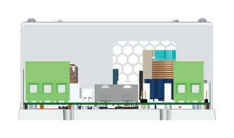


61
62


63
64 Certificate Number: 16-HS PDA 10/NOV/2016 Confirmation of Product Type Approval Please refer to the "Service Restrictions" shown below to determine if Unit Certification is required for this product. This certificate reflects the information on the product in the ABS Records as of the date and time the certificate is printed. Pursuant to the Rules of the American Bureau of Shipping (ABS), the manufacturer of the below listed product held a valid Manufacturing Assessment (MA) with expiration date of 30/MAY/2018. The continued validity of the Manufacturing Assessment is dependent on completion of satisfactory audits as required by the ABS Rules. And; a Product Design Assessment (PDA) valid until 31/OCT/2021 subject to continued compliance with the Rules or standards used in the evaluation of the product. The above entitle the product to be called Product Type Approved. The Product Design Assessment is valid for products intended for use on ABS classed vessels, MODUs or facilities which are in existence or under contract for construction on the date of the ABS Rules used to evaluate the Product. ABS makes no representations regarding Type Approval of the Product for use on vessels, MODUs or facilities built after the date of the ABS Rules used for this evaluation. Due to wide variety of specifications used in the products ABS has evaluated for Type Approval, it is part of our contract that; whether the standard is an ABS Rule or a non-abs Rule, the Client has full responsibility for continued compliance with the standard. Presented to: STORED ENERGY SYSTEMS, LLC 1840 INDUSTRIAL CIRCLE United States Product Name: Battery Charger Model Name(s): MicroGenius 2 Intended Service: Description: Ratings: Service Restrictions: Comments: Notes / Documentation: Marine and Offshore Applications MicroGenius 2: Switchmode, regulated, filtered, microprocessor-controlled, current limited battery charger designed for heavy-duty industrial service. Primary application: quick recharge and long-life maintenance of engine start batteries and ultracapacitors. Refer to the attached sheet for Model Series Designation. Output Voltage: 12 or 24 VDC Nominal; Output Power: 180 W, 300W, or 450W Input Voltage: VAC Input Frequency: 50/60 Hz; Operational temperature at full rated output: -40 ºC to +55 ºC for 180W; -40 ºC to +50 ºC for 300W; -40ºC to +40ºC for 450W Enclosure: IP 22 aluminum/stainless steel enclosure; Unit Certification is not required for this product. If the manufacturer or purchaser request an ABS Certificate for compliance with a specification or standard, the specification or standard, including inspection standards and tolerances, must be clearly defined. Not suitable for installation in hazardous areas. The Manufacturer has provided a declaration about the control of, or the lack of Asbestos in this product. 1. End user must use output cables that have sufficient current carrying capacity as per ABS Steel Vessel Rules 4-8-2/ Drawing No. COMPLIANCE SPEC, MicroGenius 2, Pages: 7 Drawing No. 2DCAD-MG2-STD-ENC, Charger drawing, Revision: B, Pages: 2 Drawing No. Alarm list, ABS alarm reqs mapped to MG2 charger, Pages: 1 Drawing No. MG2_ABS_Discharge_ , Charge curves, Pages: 89 Drawing No. 11/10/ :27:53 PM Copyright 2001 American Bureau of Shipping. All rights reserved. Page 1 of 2
65 Certificate Number: 16-HS PDA Term of Validity: ABS Rules: MG2_ABS_Recharge_ , MG2_ABS_Recharge_ , Pages: 71 Drawing No. MicroGenius_2_Model_Designation, Pages: 1 Drawing No. SENS IP 22 Test, SENS IP 22 Test Report, Pages: 10 Drawing No. UL File E Project , UL_Reverse_Polarity_Test, Pages: 1 Drawing No. UL Project , SENS UL NofA Sep , Pages: 1 Drawing No. EMI Test Lab LLC EMC Test Report, Revision: 1.0, Pages 65. Drawing No. ISO_Platinum_Cert_2008_RevD, ISO_Platinum_Cert_2008_RevD, Pages: 1 Drawing No. ISO_SENS RA Report, ISO_SENS RA Report, Pages: 1 Drawing No. 2016_ABS_Certificate_Manufacturing_Assessment, Pages: 1 This Product Design Assessment (PDA) Certificate 16-HS PDA, dated 01/Nov/2016 remains valid until 31/Oct/2021 or until the Rules or specifications used in the assessment are revised (whichever occurs first). This PDA is intended for a product to be installed on an ABS classed vessel, MODU or facility which is in existence or under contract for construction on the date of the ABS Rules or specifications used to evaluate the Product. Use of the Product on an ABS classed vessel, MODU or facility which is contracted after the validity date of the ABS Rules and specifications used to evaluate the Product, will require re-evaluation of the PDA. Use of the Product for non ABS classed vessels, MODUs or facilities is to be to an agreement between the manufacturer and intended client. The Rules for Conditions of Classification, Part Steel Vessels Rules 1-1-4/7.7, 1-1-A3, 1-1-A4, which covers the following: 2016 Steel Vessel Rules: 4-8-3/1.11.1, 4-8-3/5.9; 2016 Offshore Support Vessels Rules: 4-8-3/1.11.1, 4-8-3/5.9; 2016 Steel Vessels Under 90M length: 4-6-3/3.1.3(a), 4-6-4/7.19. The Rules for Conditions of Classification, Part Offshore Units and Structures 1-1-4/9.7, 1-1-A2, 1-1-A3, which covers the following: 2016 Mobile Offshore Drilling Unit Rules: 4-3-3/3.1.1(a), 6-1-7/9.17. National Standards: UL 1236 Battery Chargers for Charging Engine-Starter Batteries, Edition 8 (UL File E and EX6409). International Standards: CSA 22.2 No (2011), Battery Chargers (UL File E109740); IEC Degrees of Protection Provided by Enclosures (IP Code), 1989+A1:1999; EN : 2007+A1:2011 Electromagnetic compatibility (EMC). Generic standards; EN : 2005 Electromagnetic compatibility (EMC). Generic standards. Immunity for industrial environments. Government Authority: EUMED: Others: Model Certificate Model Certificate No Issue Date Expiry Date PDA 16-HS PDA 01/NOV/ /OCT/2021 ABS Programs ABS has used due diligence in the preparation of this certificate and it represents the information on the product in the ABS Records as of the date and time the certificate was printed. Type Approval requires Drawing Assessment, Prototype Testing and assessment of the manufacturer's quality assurance and quality control arrangements. Limited circumstances may allow only Prototype Testing to satisfy Type Approval. The approvals of Drawings and Products remain valid as long as the ABS Rule, to which they were assessed, remains valid. ABS cautions manufacturers to review and maintain compliance with all other specifications to which the product may have been assessed. Further, unless it is specifically indicated in the description of the product; Type Approval does not necessarily waive witnessed inspection or survey procedures (where otherwise required) for products to be used in a vessel, MODU or facility intended to be ABS classed or that is presently in class with ABS. Questions regarding the validity of ABS Rules or the need for supplemental testing or inspection of such products should, in all cases, be addressed to ABS. 11/10/ :27:53 PM Copyright 2001 American Bureau of Shipping. All rights reserved. Page 2 of 2

66 EC Declaration of Conformity In accordance with EN ISO :2004 Manufacturer: Manufacture Address: Product Type: Model Numbers: Conformance to Directives: Stored Energy Systems 1840 Industrial Circle Longmont, CO U.S.A. MicroGenius 2 Battery Charger MX-YY-YYYY-YY, where X = 1, 3, 4, F, G, H; Y = any digit; Directive 2014/30/EU of the European Parliament and of the Council of 26 February 2014 on the harmonisation of the laws of the Member States relating to electromagnetic compatibility (recast) Directive 2014/35/EU of the European Parliament and of the Council of 26 February 2014 on the harmonisation of the laws of the Member States relating to the making available on the market of electrical equipment designed for use within certain voltage limits (recast) Directive 2011/65/EU of the European Parliament and of the Council of 8 June 2011 on the restriction of the use of certain hazardous substances in electrical and electronic equipment (recast) Harmonized and/or technical specifications applied in full: Directive 2014/30/EU (EMC) EN :2005/AC:2005 EN :2007/A1:2011 Class B Directive 2014/35/EU (LVD) EN :2012/A11:2014 EN :2004/A2:2010 Directive 2011/65/EU (RoHS (recast)) EN 50581:2012 Place and date of first issue: Longmont, CO USA on October 20, 2016 Under the sole responsibility of Stored Energy Systems, the undersigned hereby declares that the equipment specified above conforms to the essential requirements of the above Directives(s) and Standard(s). 11/28/2016. Sam Coleman Date Compliance Manager Stored Energy Systems, LLC STORED ENERGY SYSTEMS 1840 INDUSTRIAL CIRCLE, LONGMONT, COLORADO FAX A LIMITED LIABILITY COMPANY info@sens-usa.com FORM-297 REV A DATE ISSUED: 11/28/2016
Intelligent Battery Charger
 Intelligent Battery Charger Model Power 12V Output 24V Output MicroGenius 180 180 watts 10 amps 6 amps MicroGenius 300 300 watts 12 amps 10 amps MicroGenius 450 450 watts 15 amps 15 amps Small. Powerful.
Genset Battery Chargers
 Genset attery Chargers 12 & 24 Volts, 6 to 60 mps Small. Powerful. Rugged. Hardened switchmode powertrain - delivers first-class abuse resistance and energy efficiency Patented charging algorithms - recharge
Safety, Installation and Operating Instructions Instructions importantes concernant la sécurité
 ! Safety, Installation and Operating Instructions Instructions importantes concernant la sécurité Manual for the following Battery Fuel Gauge models: BFGOV12V, BFGOV24V, BFGOV36V, BFGOV48V, BFGOV64V and
Marine Power Battery Chargers
 Marine Power attery Chargers 12 & 24 Volts, 6 to 60 mps Powerful. Rugged. Reliable. Convection-cooled high efficiency design - minimizes ingress of failure-causing dirt and salt ull output power - guaranteed
Installation & Operation Manual
 Installation & Operation Manual NRG12-20: 12-Volt, 20-Amp Battery Charger NRG24-20: 24-Volt, 20-Amp Battery Charger NRG22-20: 12/24-Volt, 20-Amp Battery Charger SENS Part Number: Document Revision: DCN
AUTOMATIC BEST BATTERY SELECTOR INSTALLATION & OPERATION BBS-4800 BBS-4800E
 AUTOMATIC BEST BATTERY SELECTOR INSTALLATION & OPERATION BBS-4800 BBS-4800E SENS part no: 101312 Document revision: K DCN No. 107455 Date 4/2/18 1840 Industrial Circle Longmont, CO 80501 Fax: (303) 678-7504
Industrial Reserve Power Battery Chargers
 Industrial Reserve Power attery Chargers 12 & 24 Volts, 6 to 60 mps Small. Powerful. Rugged. Hardened switchmode powertrain - delivers first-class abuse resistance and energy efficiency dvanced microprocessor
AUTOMATIC BEST BATTERY SELECTOR INSTALLATION & OPERATION BBS-1600 BBS-1600E
 AUTOMATIC BEST BATTERY SELECTOR INSTALLATION & OPERATION BBS-1600 BBS-1600E SENS part no: 101314 Document revision: H DCN No. 107395 Date 11/22/17 1840 Industrial Circle Longmont, CO 80501 Fax: (303) 678-7504
Safety, Installation and Operating Instructions Instructions importantes concernant la sécurité
 Safety, Installation and Operating Instructions Instructions importantes concernant la sécurité Manual for the Following Battery Discharger: BD6812QUAD 022118-70329 IMPORTANT NOTICE: Please save and read
BATTERY CHARGER CHR-1445
 BATTERY CHARGER CHR-1445 / 2685 TEL:886-4-2238-0698 FAX:886-4-2238-0891 Web Site:http://www.monicon.com.tw E-mail:sales@monicon.com.tw Copyright 2007 Monicon Instruments Co., Ltd. All right reserved. Contents
Safety, Installation and Operating Instructions Instructions importantes concernant la sécurité
 Safety, Installation and Operating Instructions Instructions importantes concernant la sécurité Manual for the Following Battery Charger Models: 1250OB, 2440OB, 2450OB and 4836OB 030713 IMPORTANT NOTICE:
Sentry Battery Charger. Installation and Operations Manual Section 75
 Sentry Battery Charger Installation and Operations Manual 00-02-0616 03-03-08 Section 75 In order to consistently bring you the highest quality, full featured products, we reserve the right to change our
Safety, Installation and Operating Instructions Instructions importantes concernant la sécurité
 Safety, Installation and Operating Instructions Instructions importantes concernant la sécurité Manual for the Following Battery Charger Models i2412, i3612, i4809, i2425, i3625, and i4818 081808 IMPORTANT
Safety, Installation and Operating Instructions Instructions importantes concernant la sécurité
 Safety, Installation and Operating Instructions Instructions importantes concernant la sécurité Manual for the Following Battery Charger Models: 1212, 1212OB, 1225, 1225OB, 2412, 2412OB, 2420, 2420OB,
Guardian Battery Charger Series. Installation and Operations Manual Section 75
 Guardian Battery Charger Series Installation and Operations Manual 00-02-0615 02-29-08 Section 75 In order to consistently bring you the highest quality, full featured products, we reserve the right to
Safety, Installation and Operating Instructions Instructions importantes concernant la sécurité
 Safety, Installation and Operating Instructions Instructions importantes concernant la sécurité Manual for the Following Battery Charger Models: 1212, 1212OB, 2412, 2412OB, 3612, 3612OB, 3617, 3617OB,
OPERATOR'S MANUAL IMPORTANT SAFETY INSTRUCTIONS
 ASSOCIATED OPERATOR'S MANUAL IMPORTANT SAFETY INSTRUCTIONS MODEL 6366 12 VOLT, 0-20 AMP 4 X 20 BATTERY CHARGER 1. SAVE THESE INSTRUCTIONS. This manual contains important safety and operating instructions
MODEL 6010A 6 12 VOLT BATTERY CHARGER ASSOCIATE
 MODEL 600A 6 VOLT BATTERY CHARGER ASSOCIATE IMPORTANT SAFETY INSTRUCTIONS. SAVE THESE INSTRUCTIONS. This manual contains important safety and operating instructions for the battery charger you have purchased.
LESTRONIC II BATTERY CHARGER MODEL 07210
 LESTRONIC II BATTERY CHARGER MODEL 07210 PLEASE SAVE THESE IMPORTANT SAFETY AND OPERATING INSTRUCTIONS For correct operation of the equipment, it is important to read and be familiar with this entire manual
AUTO CHARGE 11 MODEL #: XX. AUTOMATIC BATTERY CHARGER U.L. Configuration INSTRUCTION MANUAL
 INSTRUCTION MANUAL AUTO CHARGE 11 AUTOMATIC BATTERY CHARGER U.L. Configuration MODEL #: 091-11-XX NOTE : This charger is designed for vehicles with dual batteries and negative ground. CAUTION This unit
SP6. Automatic Battery Charger. Model
 Model SP6 Automatic Battery Charger OWNERS MANUAL PLEASE SAVE THIS OWNERS MANUAL AND READ BEFORE EACH USE. This manual will explain how to use the charger safely and effectively. Please read and follow
IMPORTANT SAFETY INSTRUCTIONS
 1163714 1.5 AMP 12VOLT TRICKLE 1.5 AUTOMATIC AMP AUTOMATIC TRICKLE 1.5 AMP AUTOMATIC 12V12VOLT BATTERY CHARGER IMPORTANT SAFETY INSTRUCTIONS 1. SAVE THESE INSTRUCTIONS This product offers a wide range
Models: SP3, SPSS3 Automatic Battery Charger
 OWNERS MANUAL Models: SP3, SPSS3 Automatic Battery Charger PLEASE SAVE THIS OWNERS MANUAL AND READ BEFORE EACH USE. This manual will explain how to use the charger safely and effectively. Please read and
AUTO CHARGE 12 AUTOMATIC BATTERY CHARGER
 INSTRUCTION MANUAL FILE: 091-165-12 reve Rev: E, page 8 DATE: 7-02-15 AUTO CHARGE 12 AUTOMATIC BATTERY CHARGER MODEL #091-165-12 NOTE : This charger is designed for vehicles with a single battery and negative
10AMP FULLY AUTOMATIC 6V & 12V BATTERY CHARGER OWNER'S MANUAL
 1244502 10AMP FULLY AUTOMATIC 6V & 12V BATTERY CHARGER OWNER'S MANUAL 1. IMPORTANT SAFETY INSTRUCTIONS 1.1 SAVE THESE INSTRUCTIONS This manual contains important safety and operating instructions. 1.2
Palomino BATTERY CHARGERS. Installation and Operating Instructions. One Technology Place Caledonia, New York The Power of Excellence
 Palomino BATTERY CHARGERS Installation and Operating Instructions One Technology Place Caledonia, New York 14423 The Power of Excellence FM1320 REV - B IMPORTANT SAFETY INSTRUCTIONS INSTRUCTIONS IMPORTANTES
MODEL A96 SERIES. 130Vdc Switchmode Utility Rectifier / Battery Charger. Used with LaMarche Power Cage ECN/DATE
 MODEL A96 SERIES 130Vdc Switchmode Utility Rectifier / Battery Charger Used with LaMarche Power Cage CPN112138 ECN/DATE ISSUE DATE: ECN 17010-12/05 106 BRADROCK DRIVE DES PLAINES, IL. 60018-1967 (847)
12V 1 AMP (1000 ma) Automatic Battery Charger & Maintainer
 Automatic Battery Charger & Maintainer") 12V 1 AMP (1000 ma) Automatic Battery Charger & Maintainer For lead-acid batteries THIS MANUAL CONTAINS IMPORTANT SAFETY AND OPERATING INSTRUCTIONS FOR 12V BATTERY CHARGER: YUA1201000 / INT1201000 KEEP
12V 1 AMP (1000 ma) Automatic Battery Charger & Maintainer For lead-acid batteries THIS MANUAL CONTAINS IMPORTANT SAFETY AND OPERATING INSTRUCTIONS FOR 12V BATTERY CHARGER: YUA1201000 / INT1201000 KEEP
MODEL 6017 OPERATOR'S MANUAL
 MODEL 6017 OPERATOR'S MANUAL ASSOCIATE D IMPORTANT SAFETY INSTRUCTIONS 1. SAVE THESE INSTRUCTIONS. This manual contains important safety and operating instructions for the battery charger you have purchased.
BATTERY SAVER LOW RIPPLE HO
 INSTRUCTION MANUAL BATTERY SAVER LOW RIPPLE HO LOW RIPPLE POWER SUPPLY / AUTOMATIC LOAD SWITCH FOR 12VDC VEHICLE SYSTEMS MODEL #: 091-195-12 INPUT: 120 Volt, 50/60 Hz, 4.5 Amps RMS OUTPUT: 13.2 Volts DC,
OWNER S MANUAL. Model YUA2AMPCH 2 AMP Dual-Bank Automatic Battery Charger & Maintainer READ ENTIRE MANUAL BEFORE USING THIS PRODUCT
 Model YUA2AMPCH 2 AMP Dual-Bank Automatic Battery Charger & Maintainer Certified by California BCS Regulations OWNER S MANUAL READ ENTIRE MANUAL BEFORE USING THIS PRODUCT READ ENTIRE MANUAL BEFORE USING
10 AMP ON BOARD BATTERY CHARGER
 R A Valley Forge Company MODEL 2611A-1-B 10 AMP ON BOARD BATTERY CHARGER One Output OWNER S MANUAL IMPORTANT! READ THESE INSTRUCTIONS BEFORE INSTALLING AND USING THIS PRODUCT. Keep these instructions for
AC CONVERTER / BATTERY CHARGER
 AC CONVERTER / BATTERY CHARGER User s Manual MODEL #: CON120AC12/24VDC Listed to UL 458 and CSA 22.2 NO. 107.1 Standards Contents INTRODUCTION... 3 Important Safety Instructions... 3 1. General Description...
Troubleshooting Guide
 Troubleshooting Guide Current Revision: June 2009 Table of Contents PAGE IMPORTANT NOTES ------------------------------------------------------------------- 3 20T Main Electrical System --------------------------------------------------------------
PUMP PLUS 2000 PLC MODEL #: PP AUTOMATIC DUAL OUTPUT BATTERY CHARGER INSTRUCTION MANUAL
 INSTRUCTION MANUAL PUMP PLUS 2000 PLC AUTOMATIC DUAL OUTPUT BATTERY CHARGER Supplied with Dual Bar Graph Display MODEL #: 091-237-12-PP INPUT: 120 Volt, 60 Hz, 3.5 Amps OUTPUT BATTERY 1 and 2: 15 or 18
Deltran Battery Tender 6V/12V 4Amp 5 & 10 Bank Battery Management System TABLE 1. Length of Cord, Feet AWG Size of Cord
 Deltran Battery Tender 6V/12V 4Amp 5 & 10 Bank Battery Management System Designed for Six-cell and three-cell Flooded/AGM/GEL Lead-Acid Batteries and Four-Cell Lithium Iron Phosphate (LiFePO4) Batteries
AUTO CHARGE 4000 MODEL #: LOW PROFILE CHARGER AUTOMATIC DUAL OUTPUT BATTERY CHARGER INSTRUCTION MANUAL
 INSTRUCTION MANUAL AUTO CHARGE 4000 LOW PROFILE CHARGER AUTOMATIC DUAL OUTPUT BATTERY CHARGER Unit supplied with this display MODEL #: 091-89-12 INPUT: 120 Volt, 50/60 Hz, 5 Amps OUTPUT: 45 Amps File:
801 BUSINESS CENTER DRIVE MOUNT PROSPECT, ILLINOIS
 280-600 Send Warranty Product Repairs to: 1025 E. Thompson Ave., Hoopeston, IL 60942-0280. Call Customer Service if you have questions: 1-800-621-5485 A. IMPORTANT SAFETY INSTRUCTIONS 1. SAVE THESE INSTRUCTIONS
AUTO CHARGE DUAL MODEL #: AUTOMATIC DUAL OUTPUT BATTERY CHARGER INSTRUCTION MANUAL. Ph: Fax:
 INSTRUCTION MANUAL AUTO CHARGE DUAL AUTOMATIC DUAL OUTPUT BATTERY CHARGER MODEL #: 091-145-12 INPUT: 120 Volt, 50/60 Hz, 3.5 Amps OUTPUT BAT 1: 10 Amps OUTPUT BAT 2: 10 Amps File: IM_091-145-12_revb.indd
INSTRUCTION MANUAL. 12-Station HD Shop 12V Portable Battery Charger
 INSTRUCTION MANUAL 12-Station HD Shop 12V Portable Battery Charger IMPORTANT SAFETY INSTRUCTIONS 1. SAVE THESE INSTRUCTIONS This manual contains important safety and operating instructions for your HD
2/10/50 AMP 12 VOLT BATTERY CHARGER/ ENGINE STARTER
 2/10/50 AMP 12 VOLT BATTERY CHARGER/ ENGINE STARTER WARNING This product contains or, when used, produces a chemical known to the State of California to cause cancer and birth defects or other reproductive
MASTERsine Inverter PXA Series Installation Guide
 Backup Power System Expert TM MASTERsine Inverter PXA Series Installation Guide Important Safety Instructions IMPORTANT: Read and save this Installation Guide for future reference. This chapter contains
Art. No. EC-315. Art. No. EC-330. Art. No. EC-340 SWITCH-MODE BATTTERY CHARGER CONTENTS IMPORTANT SAFETY PRECAUTIONS... 2
 SWITCH-MODE BATTTERY CHARGER CONTENTS IMPORTANT SAFETY PRECAUTIONS... 2 DESCRIPTION AND FEATURES... 3 CHARGING STAGES... 4 Art. No. EC-315 Art. No. EC-330 Art. No. EC-340 PROTECTIONS... 5 INSTALLATION...
Document: PRODSPEC-140 Revision: G DCN No Date: October 1, 2014 Product: 10-amp EnerGenius NRG Battery Charger
 Document: PRODSPEC-140 Revision: G DCN No. 106512 Date: October 1, 2014 Product: 10-amp EnerGenius NRG Battery Charger 1. GENERAL DESCRIPTION 1.1 General Description Fully regulated, constant voltage,
IMPORTANT SAFETY INSTRUCTIONS IMPORTANT: READ AND SAVE THIS SAFETY AND INSTRUCTION MANUAL. KEEP IT WITH OR NEAR CHARGER AT ALL TIMES.
 IMPORTANT SAFETY INSTRUCTIONS IMPORTANT: READ AND SAVE THIS SAFETY AND INSTRUCTION MANUAL. KEEP IT WITH OR NEAR CHARGER AT ALL TIMES. SPECIFICATIONS: For technical assistance, call your Dealer with the
Model: SE-4020-CA Automatic Battery Charger
 OWNERS MANUAL Model: SE-4020-CA Automatic Battery Charger PLEASE SAVE THIS OWNERS MANUAL AND READ BEFORE EACH USE. This manual will explain how to use the battery charger safely and effectively. Please
LPC 20 MODEL #: LOW PROFILE CHARGER AUTOMATIC SINGLE OUTPUT BATTERY CHARGER INSTRUCTION MANUAL
 INSTRUCTION MANUAL LPC 20 LOW PROFILE CHARGER AUTOMATIC SINGLE OUTPUT BATTERY CHARGER Unit supplied with one of these displays MODEL #: 091-207-12 INPUT: 120 Volt, 50/60 Hz, 7 Amps OUTPUT: 20 Amps File:
AUTO CHARGE 12 HO MODEL #: MODEL #: MODEL #: AUTOMATIC SINGLE OUTPUT BATTERY CHARGER INSTRUCTION MANUAL
 INSTRUCTION MANUAL AUTO CHARGE 12 HO AUTOMATIC SINGLE OUTPUT BATTERY CHARGER MODEL #: 091-170-6 MODEL #: 091-170-12 MODEL #: 091-170-24 File: IM_091-170-xx_revd.indd Rev: D Revised By: MFG Date: 10-23-2013
801 BUSINESS CENTER DRIVE MOUNT PROSPECT, ILLINOIS Ext. 322
 277-999 ELECTRIC CORP. 801 BUSINESS CENTER DRIVE MOUNT PROSPECT, ILLINOIS 800-621-5485 Ext. 322 Send Warranty Product Repairs to: 605 South Vermilion, Suite C, Brownsville, TX 78521-6851 Call Customer
AUTO CHARGE D2 MODEL #: AUTOMATIC TRIPLE OUTPUT BATTERY CHARGER INSTRUCTION MANUAL
 INSTRUCTION MANUAL AUTO CHARGE D2 AUTOMATIC TRIPLE OUTPUT BATTERY CHARGER Designed Specifically for Vehicles with DDEC ENGINES MODEL #: 091-74-12 INPUT: 120 Volt, 60 Hz, 8 Amps OUTPUT VEHICLE BATTERY 1
User Manual. Solar Charge Controller 3KW
 User Manual Solar Charge Controller 3KW 1 CONTENTS 1 ABOUT THIS MANUAL... 3 1.1 Purpose... 3 1.2 Scope... 3 1.3 SAFETY INSTRUCTIONS... 3 2 INTRODUCTION... 4 2.1 Features... 4 2.2 Product Overview... 5
AUTO CHARGE 4000 MODEL #: AUTOMATIC DUAL OUTPUT BATTERY CHARGER INSTRUCTION MANUAL. Ph: Fax:
 INSTRUCTION MANUAL AUTO CHARGE 4000 AUTOMATIC DUAL OUTPUT BATTERY CHARGER MODEL #: 091-89-12 INPUT: 120 Volt, 50/60 Hz, 8 Amps OUTPUT BATTERY CHARGER: 40 Amps OUTPUT BATTERY SAVER: 5 Amps File: IM_091-89-12_reve.indd
BatteryMINDer 1500* & BatteryMINDer Plus 1510*
 BatteryMINDer 1500* & BatteryMINDer Plus 1510* both with SmarTECHnology 12 Volt 1500 ma Charger - Maintainer - Desulfator INCLUDES: Auto-Temp Compensation Sensor, installed (1500 & 1510) Optional Permanent
Sentinel 150 series Automatic switch mode battery chargers Installation, Operation and Maintenance
 yi6503 2016-04-29 Sentinel 150 series Automatic switch mode battery chargers Installation, Operation and Maintenance Open frame models Enclosed models This Manual Refers to the Following Models Standard
ACCUSENSE CHARGE SERIES ON/OFF BOARD FULLY AUTOMATIC BATTERY CHARGER
 ACCUSENSE CHARGE SERIES ON/OFF BOARD FULLY AUTOMATIC BATTERY CHARGER SPECIFICATIONS: *Photo for reference only* Part number 8890439 Mode Select: Selects Battery Type Refer to Section 6. IMPORTANT: READ
MODEL A97 SERIES. Switchmode Utility Rectifier/Battery Charger ECN/DATE
 MODEL A97 SERIES Switchmode Utility Rectifier/Battery Charger CPN108172 ISSUE DATE: 16071 7/03 ECN/DATE 106 BRADROCK DRIVE DES PLAINES, IL. 60018-1967 (847) 299-1188 FAX: (847)299-3061 Page 1 of 7 INSTRUCTION
INTELLIGENT BATTERY CHARGER/MAINTAINER
 INTELLIGENT BATTERY CHARGER/MAINTAINER OWNER S MANUAL Read carefully and understand all ASSEMBLY AND OPERATION INSTRUCTIONS before operating. Failure to follow the safety rules and other basic safety precautions
AUTO CHARGE D PUMP PLUS
 INSTRUCTION MANUAL AUTO CHARGE D PUMP PLUS AUTOMATIC DUAL OUTPUT BATTERY CHARGER Designed Specifically for Vehicles with DDEC ENGINES MODEL #: 091-9-DPP INPUT: 120 Volt, 60 Hz, 8 Amps OUTPUT VEHICLE BATTERY:
LC BATTERY CHARGER OPERATION & MAINTENANCE GUIDE
 LC BATTERY CHARGER OPERATION & MAINTENANCE GUIDE SENS part number: 101194 Document revision: D DCN number: 105128 Date: 3/23/2006 1840 Industrial Circle Longmont, CO 80501 Fax: 303-678-7504 Tel: 303-678-7500
12 Volt 1500 ma Convertible Charger - Maintainer - Desulfator*
 1215C 12 Volt 1500 ma Convertible Charger - Maintainer - Desulfator* INCLUDES: Auto-Temp Compensation Sensor, installed Optional Permanent Mounting Brackets and screws Battery Clips (Fully-Insulated 6
Cruising Charger Series OWNER S MANUAL
 R Cruising Charger Series OWNER S MANUAL ON BOARD BATTERY CHARGERS Models DC Amperage No. Of Banks Volts 2614A 5,10 Amps 2 Bank 12/12 2614A-230 2621A 5,5,10 Amps 3 Banks 12/12/12 2621A-230 2622A 10,10
FC/FCA 12, 24, 32 & 48 VOLT, 6 & 10 AMP BATTERY CHARGER OPERATION & MAINTENANCE GUIDE
 FC/FCA 12, 24, 32 & 48 VOLT, 6 & 10 AMP BATTERY CHARGER OPERATION & MAINTENANCE GUIDE SENS part number: 101037 Document revision: A Engineering change number: 105073 Date: 1/13/2006 1840 Industrial Circle
LESTRONIC II BATTERY CHARGER BUILT-IN OR PORTABLE CHARGERS
 LESTRONIC II BATTERY CHARGER BUILT-IN OR PORTABLE CHARGERS PLEASE SAVE THESE IMPORTANT SAFETY AND OPERATING INSTRUCTIONS For correct operation of the equipment, it is important to read and be familiar
Intelligent Engine Start Battery Charger. The Smart Choice for Mission-Critical Engine Starting
 NRG Intelligent Engine Start Battery Charger The Smart Choice for Mission-Critical Engine Starting Fast, accurate, mission-critical charging gives best starting reliability Replace nearly any charger without
PUMP PLUS 1000 PLC MODEL #: PP AUTOMATIC SINGLE OUTPUT BATTERY CHARGER INSTRUCTION MANUAL
 INSTRUCTION MANUAL PUMP PLUS 1000 PLC AUTOMATIC SINGLE OUTPUT BATTERY CHARGER Unit supplied with one of these displays MODEL #: 091-215-12-PP INPUT: 120 Volt, 60 Hz, 3.5 Amps OUTPUT BATTERY 1 and 2: 15
LESTRONIC II BATTERY CHARGER MODEL 19740
 *01679* LESTRONIC II BATTERY CHARGER MODEL 19740 PLEASE SAVE THESE IMPORTANT SAFETY AND OPERATING INSTRUCTIONS For correct operation of the equipment, it is important to read and be familiar with this
Installation and Operating Instructions (for chargers shown below)
") Installation and Operating Instructions (for chargers shown below) For additional information please call our Technical Support Group 800.742.2740 PRO CHARGING SYSTEMS, LLC 1551 Heil Quaker Boulevard,
Installation and Operating Instructions (for chargers shown below) For additional information please call our Technical Support Group 800.742.2740 PRO CHARGING SYSTEMS, LLC 1551 Heil Quaker Boulevard,
12V Manual Battery Charger
 OPERATOR S MANUAL 12V Manual Battery Charger Model No. 28.71221 Read and follow all Safety Rules and Operating Instructions before Every Use of this Product. SAVE THESE INSTRUCTIONS. Sears Brands Management
A48 / A48B (base plate) BATTERY CHARGER
 BATTERY CHARGER") A48 / A48B (base plate) BATTERY CHARGER CPN41054 ISSUE DATE: 12315-8/98 ECN/DATE 106 BRADROCK DRIVE DES PLAINES, IL. 60018-1967 (847) 299-1188 FAX: (847)299-3061 15349-07-07/02 16041 6/03 14575-2/01 INSTRUCTION
A48 / A48B (base plate) BATTERY CHARGER CPN41054 ISSUE DATE: 12315-8/98 ECN/DATE 106 BRADROCK DRIVE DES PLAINES, IL. 60018-1967 (847) 299-1188 FAX: (847)299-3061 15349-07-07/02 16041 6/03 14575-2/01 INSTRUCTION
ELECTRONIC MARINE CONVERTER/CHARGER Owners Manual Models PD2020, PD2030, PD2040, PD2050, PD2060, PD2080
 Table Of Contents ELECTRONIC MARINE CONVERTER/CHARGER Owners Manual Models PD2020, PD2030, PD2040, PD2050, PD2060, PD2080 Thank you for purchasing the INTELI-POWER MARINE converter/charger. The INTELI-POWER
LPC 40 MODEL #: LOW PROFILE CHARGER WITH PLC AUTOMATIC SINGLE OUTPUT BATTERY CHARGER INSTRUCTION MANUAL
 INSTRUCTION MANUAL LPC 40 LOW PROFILE CHARGER WITH PLC AUTOMATIC SINGLE OUTPUT BATTERY CHARGER Unit supplied with one of these displays MODEL #: 091-200-12 INPUT: 120 Volt, 50/60 Hz, 5 Amps OUTPUT: 40
User Manual Solar Charge Controller 3KW
 User Manual Solar Charge Controller 3KW Version: 1.3 CONTENTS 1 ABOUT THIS MANUAL... 1 1.1 Purpose... 1 1.2 Scope... 1 1.3 SAFETY INSTRUCTIONS... 1 2 INTRODUCTION... 2 2.1 Features... 2 2.2 Product Overview...
Operating Instructions
 Operating Instructions PRO- If you sell, inventory or service lead-acid batteries, you want the battery you take off the shelf to be as new as the day it was manufactured. However, batteries that sit idle
EASY CHARGE Waterproof portable Battery Charger
 EASY CHARGE Waterproof portable Battery Charger 1.1 AND 4.3 AMP MODELS EN NL, DE, FR, ES, IT USER S MANUAL WWW.MASTERVOLT.COM/EASYCHARGE-PORTABLE 10000009117/04 2 EN / EasyCharge 1.1 and 4.3 Amp - User
CRS1, CRS2 and CRS3. For additional information please call our. PRO CHARGING SYSTEMS, LLC 1551 Heil Quaker Boulevard, LaVergne, TN
 CRS1, CRS2 and CRS3 For additional information please call our Technical Support Group 800.742.2740 PRO CHARGING SYSTEMS, LLC 1551 Heil Quaker Boulevard, LaVergne, TN 37086-3539 110310 Installation and
EASY CHARGE Weather-resistant fixed mount Battery Charger
 EASY CHARGE Weather-resistant fixed mount Battery Charger 6 AMP AND 10 AMP MODELS EN NL, DE, FR, ES, IT USER S MANUAL WWW.MASTERVOLT.COM/EASYCHARGE 10000009118/01 2 EN / EasyCharge 6 and 10 Amp - User
Intelligent Charging System Series
 R Intelligent Charging System Series OWNER S MANUAL ON BOARD BATTERY CHARGERS Models Amperage No. Of Banks Volts 16061 s 1 Bank 12 16102 6,s 2 Banks 12 or 24 16153 6,6,s 3 Banks 12 or 24 or 36 16202 10,10
24 VOLT AUTOMATIC BATTERY CHARGER PART NO
 24 VOLT AUTOMATIC BATTERY CHARGER PART NO. 957732 AC Input: DC Output: Battery Type: Specifications 230 volts, 50 hertz, 3.5 amps, single-phase 24 volts, 20 amps initially tapering to 6 amps 24 volt, 12
Battery. Charger Model: Save Important Safety Instructions
 Owner's Manual Battery Charger Model: SS-51A-PE, 10 Amp Fully Automatic Battery Charger For 12 Volt Marine Deep Cycle & Automotive Batteries Save Important Safety Instructions Read Rules for Safe Operation
Safety, Installation And Operating Instructions For The Following Battery Charger Models: i2412, i3612, i4809, i2425, i3625, and i4818
 Safety, Installation And Operating Instructions For The Following Battery Charger Models: i2412, i3612, i4809, i2425, i3625, and i4818 IMPORTANT NOTICE: Please save and read these safety, operating and
12V/25A BATTERY CHARGER MAINTAINER / JUMPSTARTER
 12V/25A BATTERY CHARGER MAINTAINER / JUMPSTARTER OWNER S MANUAL Read carefully and understand all ASSEMBLY AND OPERATION INSTRUCTIONS before operating. Failure to follow the safety rules and other basic
FULLY AUTOMATIC SCR BATTERY CHARGER
 *35589* FULLY AUTOMATIC SCR BATTERY CHARGER FEATURES Microprocessor controlled charge circuit monitors battery state of charge and automatically turns charger off when the batteries reach full charge.
A39 UNIVERSAL SCR CHARGER
 A39 UNIVERSAL SCR CHARGER ECN/DATE CPN35971 21681 01/18 16816-6/05 15349-03 05/02 14575 02/01 14268 10/00 10400 9/96 106 BRADROCK DRIVE DES PLAINES, IL. 60018-1967 (847) 299-1188 FAX: (847) 299-3061 ISSUE
CX-SERIES ADVANCED BATTERY CHARGER
 CX-SERIES ADVANCED BATTERY CHARGER Table of Content 1. IMPORTANT SAFETY INFORMATION... 2 1-1 General Safety Precautions... 2 1-2 Battery Precautions... 2 2. FEATURES... 3 2-1 Battery Charging Curve...
MODEL 2602A-12 3 STAGE AUTOMATIC BATTERY CHARGER OWNER S MANUAL SAVE THESE INSTRUCTIONS
 R A Valley Forge Company MODEL 2602A-12 3 STAGE AUTOMATIC BATTERY CHARGER OWNER S MANUAL SAVE THESE INSTRUCTIONS 1. INTRODUCING THE CHARGER The 2602A-12 is a 3-stage electronic battery charger. Rainproof,
Compact Sine Inverter
 Compact Sine Inverter Instructions for installation & use Applies to the following models: Output power: 700watt, 1000 watt, 1500watt, 2000 watt & 3000 watts Output voltage: and output, 50Hz & 60Hz Output
installation and operating instructions for the following xtreme Battery chargers:
 installation and operating instructions for the following xtreme Battery chargers: Model Name No. of Banks Amps Per Bank Battery System Dual Pro SE Xtreme Dual Pro Xtreme Three Bank SE Xtreme Three Bank
MB V 3-IN-1 JUMP STARTER WITH SPIRAL WOUND BATTERY
 MB3730 12V 3-IN-1 JUMP STARTER WITH SPIRAL WOUND BATTERY 1 IMPORTANT SAFETY INSTRUCTIONS 1. SAVE THESE INSTRUCTIONS - This manual contains important safety and operating instructions for this PowerStation.
Table of Contents 文管中心 發行章
 ST600-XXX Series Pure Sine Wave Power Inverter User s Manual Table of Contents 1. Important Safety Instructions 1-1 General Safety Precautions 1 1-2 Battery Precautions. 1 2. Basic Descriptions 2-1 Mechanical
SAVE THESE INSTRUCTIONS
 R MODEL 2611 10 AMP ON BOARD BATTERY CHARGER Two Outputs OWNER S MANUAL Connections at a glance: For the best charging results both 12 Volt independent batteries should be equally discharged. The charger
DieHard. BATTERY CHARGER/MAINTAINER 1.5 Amp Fully Automatic Float-Mode Monitoring. Model No
 OWNER'S MANUAL DieHard. BATTERY CHARGER/MAINTAINER 1.5 Amp Fully Automatic Float-Mode Monitoring Model No. 200.71220 CAUTION: Read and follow all Safety Rules and Operating Instructions Before Every Use
DBL Manual. Deutronic Battery Charger with MPC4-Board and 14VDC output voltage (12VDC lead based batteries)
") Deutronicstrasse 5 D-84166 Adlkofen / Germany Tel.: +49 (0)8707 / 920-199 Fax: +49 (0)8707 / 1004 E-Mail: sales@deutronic.com http://www.deutronic.com DBL Manual Deutronic Battery Charger with MPC4-Board
Deutronicstrasse 5 D-84166 Adlkofen / Germany Tel.: +49 (0)8707 / 920-199 Fax: +49 (0)8707 / 1004 E-Mail: sales@deutronic.com http://www.deutronic.com DBL Manual Deutronic Battery Charger with MPC4-Board
February EN-B POWER CHARGE PSC-700. Power Supply / Maintenance Charger for 12-volt Batteries/Systems INSTRUCTION MANUAL
 February 2017 167-000182EN-B POWER CHARGE PSC-700 Power Supply / Maintenance Charger for 12-volt Batteries/Systems INSTRUCTION MANUAL Blank page Contents General Safety Precautions 4 Personal Precautions
24V HEAVY DUTY JUMP STARTER/ POWER BANK MB3752. Storage. Specifications
 Storage Warning! When not in use store your instruction manual and product in a safe and dry place. Before re-use after storage it is recommended that the product is checked by a suitably qualified person
MP V 8A Electronic Smart Charger. Instruction and Information Manual
 MP7428 12V 8A Electronic Smart Charger Instruction and Information Manual In order to ensure correct and safe usage of your battery charger, you should read these instructions carefully. Please retain
innovations in battery charging
 innovations in battery charging AutomaticBatteryCharger forsealed or Valve Regulated Lead-Acid Batteries Model HPX-60 Series OperatingInstructions WARNING CONCERNING THE REMOVAL OF COVER: CAUTION: TO PREVENT
PureSine 150/300 Pure Sine Wave Inverter User s Manual
 PureSine 150/300 Pure Sine Wave Inverter User s Manual 1. Important Safety Instructions WARNING! Before you install and use your Inverter, please read and follow these safety instructions. 1-1. General
24 VOLT DUAL MODE WHEELCHAIR BATTERY CHARGER MODEL TYPE 24EL8 E&J PRODUCT NO
 24 VOLT DUAL MODE WHEELCHAIR BATTERY CHARGER MODEL 12630 TYPE 24EL8 E&J PRODUCT NO. 90483465 Specifications AC Supply: 120 volts, 60 Hertz, single-phase, 4 amps maximum DC Output: 24 volts, 8 amps, tapering
BC12M248 7 Stage Automatic Smart Battery Charger, Desulfator & Maintainer 12V, 2 / 4 / 8A FOR AGM, GEL AND WET BATTERIES USER MANUAL
 BC12M248 7 Stage Automatic Smart Battery Charger, Desulfator & Maintainer 12V, 2 / 4 / 8A FOR AGM, GEL AND WET BATTERIES USER MANUAL THIS MANUAL CONTAINS IMPORTANT SAFETY AND OPERATING INSTRUCTIONS 1 IMPORTANT
7 Stage Automatic Smart Battery Charger (FOR CHARGING 12V / 24V AGM, GEL,SLA AND WET BATTERIES) USER MANUAL
 USER MANUAL") 7 Stage Automatic Smart Battery Charger Desulphuration& Maintainer (FOR CHARGING 12V / 24V AGM, GEL,SLA AND WET BATTERIES) USER MANUAL THIS MANUAL CONTAINS IMPORTANT SAFETY AND OPERATING INSTRUCTIONS 1
7 Stage Automatic Smart Battery Charger Desulphuration& Maintainer (FOR CHARGING 12V / 24V AGM, GEL,SLA AND WET BATTERIES) USER MANUAL THIS MANUAL CONTAINS IMPORTANT SAFETY AND OPERATING INSTRUCTIONS 1