OPERATION MANUAL BREN-TRONICS, INC. P: F: Rev D
|
|
|
- Myron Berry
- 6 years ago
- Views:
Transcription


1 Rev D NSN: Copyright Bren-Tronics, Inc. 2013
2 WARNING HIGH VOLTAGES ARE PRESENT IN THE OPERATION OF THIS EQUIPMENT Avoid contact with AC supply voltage connections during installation, operation or maintenance of the battery charger. CAUTION ACID CONTAMINATES NICKEL-CADMIUM, LITHIUM-ION, LITHIUM-POLYMER and NICKEL-METAL HYDRIDE BATTERIES Every effort must be made to keep Nickel-Cadmium, Lithium-Ion, Lithium Polymer and Nickel-Metal Hydride batteries as far away as possible from Lead- Acid batteries because Lead-Acid batteries contain sulfuric acid. Do Not use the same tools and materials, such as screwdrivers, wrenches, syringes, hydrometers, and gloves for both types of batteries. Any trace of acid or acid fumes will permanently damage Nickel-Cadmium, Lithium-Ion, Lithium Polymer and Nickel-Metal Hydride batteries on contact. WARNING NO SMOKING IS PERMITTED NEAR THE CHARGING STATION Batteries can produce explosive gases during charging or discharge cycles. Never smoke or allow open flames near the charging station. NOTICE TO PERSONS RECEIVING THIS DRAWING AND/OR TECHNICAL INFORMATION: claims proprietary rights in the material disclosed herein. This drawing and/or technical information is issued in confidence for information only and may not be reproduced or used to manufacture anything shown or referred to heron without direct permission from BREN- TRONICS, INC. to the user. This drawing and/or technical information is loaned for mutual assurance and is subject to recall by BREN-TRONICS INC. at any time. This drawing and/or technical information is the property of Page 2 of 28
3 SPC Operation Manual Table of Contents 1 INTRODUCTION SCOPE TECHNICAL SPECIFICATIONS ACCESSORIES CHARGE CYCLE DESCRIPTION SEQUENTIAL CHARGING CYCLE DESCRIPTION MULTI-CHARGING CYCLE DESCRIPTION UPGRADING CHARGER SOFTWARE OPERATING PROCEDURES PANEL CONTROLS AND INDICATORS PRELIMINARY SETUP PROCEDURES CHARGING BATTERIES BATTERY CHARGER COVER LABEL SOLID RED LED TROUBLE SHOOTING FLASHING RED LED TROUBLE SHOOTING OPERATION IN EXTREME ENVIRONMENTAL CONDITIONS PREPARATION FOR MOVEMENT BATTERY STATE-OF-CHARGE DISPLAYS BATTERY CAPACITY RETENTION BATTERY STORAGE OPERATOR MAINTENANCE INSTRUCTIONS INTRODUCTION CLEANING INSPECTION BASIC FUNCTIONAL TEST SIMPLIFIED OPERATOR TROUBLESHOOTING PROCEDURES WARRANTY / REPAIR INFORMATION UPGRADE / UPDATE INFORMATION Page 3 of 28
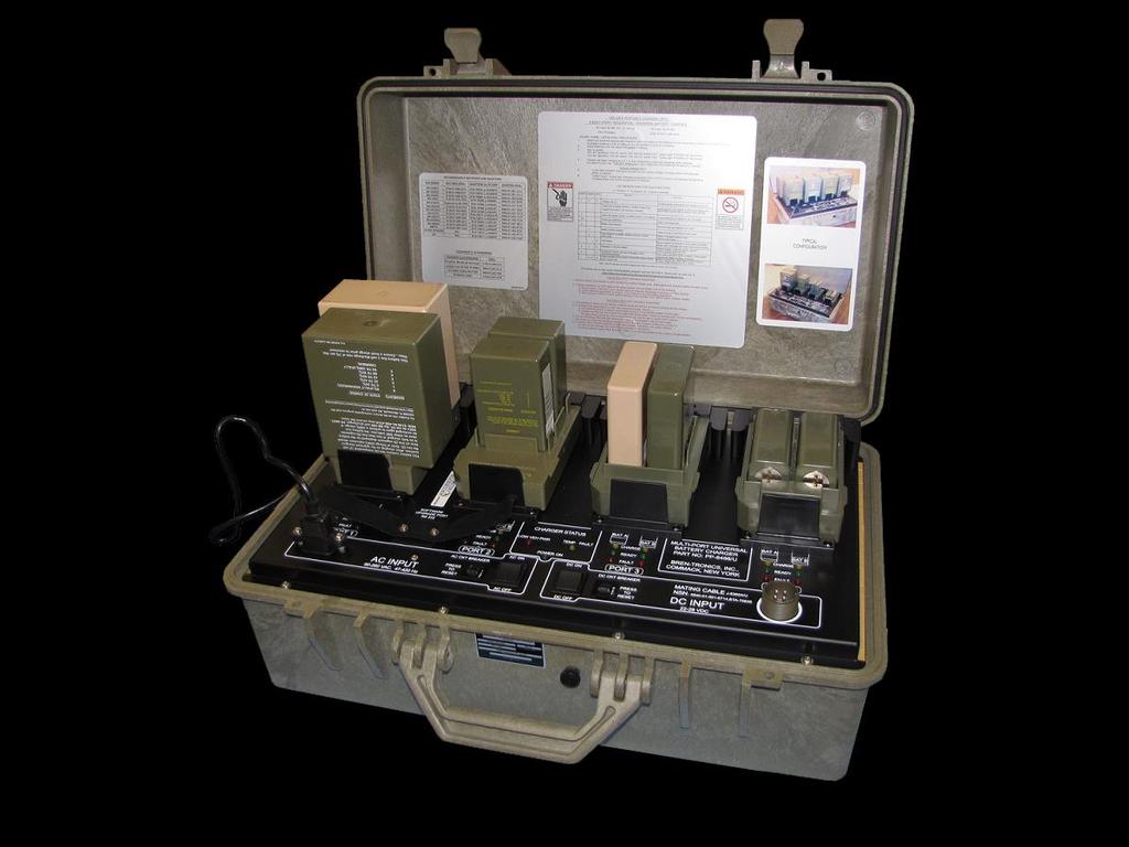
4 1 INTRODUCTION 1-1 SCOPE The Soldier Portable Charger PP-8498/U (P/N BTC-70801) is a state-of-the-art, high performance lightweight portable battery charger designed for field deployment or shop usage. It provides fast reactivation of various rechargeable batteries. It is capable of sequentially charging up to eight batteries completely unattended. The Soldier Portable Charger (SPC) is simple to use by design. Without any user intervention, the SPC typically charges up to eight batteries in approximately eight hours. Charge times are substantially less for partially discharged batteries. There are also batteries that will charge in less than two (2) hours. LED s will indicate same. It automatically identifies the specific battery type and provides the appropriate charge profile. Based on the current operating environment, the SPC automatically customizes the charge profile to provide the quickest charge in a safe manner. The charge status for each of the eight batteries is conveyed to the user via three easy-to-understand panel mounted LED indicators (amber CHARGE, green READY and red FAULT). The SPC is universal by design. It can readily use either AC or DC input power whichever is most convenient for the user. The universal AC input fully allows VAC and Hz operation without any adjustment or user intervention. Additionally, the DC input power permits a range of VDC, standard on most military vehicles. The SPC is adaptive by design. It is microprocessor controlled and is presently programmed to automatically charge over 50 different battery types as listed in the Table 1. With the appropriate battery adapter, however, it can be readily reprogrammed via RS232 software upgrade port in the field to charge a countless number of additional battery types and chemistries including: Nickel Metal Hydride, Nickel Cadmium, Lithium Ion, and Lithium Polymer. The battery charger components are housed in a durable, non-conductive ABS equipment case, as shown in Figure 1. The assembled unit is watertight when the gasketed cover is securely latched and the pressure equalization valve on the front of the case (near the carrying handle) is closed. It is shipped with four AP-390/2590 adapters. Page 4 of 28
5 1-2 TECHNICAL SPECIFICATIONS Dimensions in. (579 mm) W x 14.6 in. (371 mm) D x 9.0 in. (229 mm) H Weight lbs (12.5 kg) Power Requirements AC operation Automatic selection: 90V to 260V AC, single-phase, 47 to 420 Hz, 375 VA max, with 6.5 ft. (198 cm) detachable three-wire power cord. (Power AC = 3 Amps) DC operation VDC, 15A; with optional 12 ft (366 cm) DC cable assembly. (Power 24 VDC = 12.5 AMPs) Charging Output Voltage... Automatically selected for each battery type Duty Cycle Continuous Protective Features Resettable circuit breakers for AC (7A) and DC (20A) power sources Operating Temp. Range.-4 o F (-20 o C) to +122 o F (+50 o C) Storage Temp. Range -40 o F (-40 o C) to +158 o F (+70 o C) Loose Cargo Bounce.. Meets requirements of MIL-STD-810E, Method 514.4, Category 3 Case Material.. ABS (Acrylonitrile Butadiene Styrene) Case Color... Olive Drab #34088 per Fed-Std-595B (other colors optional) Shipment.. No restrictions Page 5 of 28
6 1-3 ACCESSORIES Table 1 shows the various batteries and appropriate adapter plates the SPC can charge as of the writing of this document. Table 2 shows various power cables and other accessories. Table 1 - Supported Batteries and Adapters ADAPTER ADAPTER NSN BATTERY FEATURE TYPE BATTERY NSN BTA BB-4600 NiCd BTA BB-503A/U NiCd BTA BB-326/U BB-516A/U NiMH NiCd BTA BB-2847A/U BB-2847/U BTA BB-586 NiCd BTA BB-386 NiMH BTA BB-2600/U BB-2600A/U BTA-70492A BT BT BT-70492A NiMH BTA BB-557/U NiCd BTA ICOM SI NiCd BTA BT-70581xx M BTA-70581A BT-70581xx M BTA ALI 124 ALI 142/BA-682A BA-682B BA-684ª NiCd BTA ALI 142/BA-682A BA-682B BA-684ª BTA ALI 116 ALI 124 ALI 142/BA-682A ALI 143/BA-687A ALI 243 BA-684A BA-685A BA-682B ALI 147 ALI 247 NiCd NiCd Page 6 of 28
7 BTA-70589A ALI 142/BA-682A ALI 143/BA-687A ALI 243 BA-684A BA-685A BA-682B ALI 147 ALI BTA BT BTA BT BTA SPR M BTA ALKABAT NiCd BTA BB-2598 BTA BT BT M M BTA BT BTA BT BTA BT M BTA BT M BTA BN-2250 NiCd BTA Motorola NNTN7032A NTN9816A NTN9815A M NiCd NiCd BTA BB-2800/U BTA BB-2588/U BB-388/U M NiMH BTA THALES MBITR BT M M BTA AA CELLS NiMH BTA BB-2557/U BB-557/U NiCd BTA D CELLS NiMH BTA BB-2590/U BT-70791A BT-70791Bx BT-70791Cx BT-70791E BB-390B/U BT NiMH SAFT BB-2590 BTA BT-70838xx BT /3xx BT /3xx M M M BTA Racal 931 NiCd BTA PTR-349 NiCd BTA Loral RT1606 NiCd BTA ATK XM25 M BTA DRT 4453/4411 M BTA LI-145 LI-80 BT M M M Page 7 of 28
8 BT M BTA BB-NM10 NiCd BTA RIFLEMAN LIBERTY M BTA BB-2590/U (See Note 6) BT-70791A (See Note 6) BT-70791Bx (See Note 6) BT-70791Cx (See Note 6) BT-70791E (See Note 6) BB-390B/U NiMH BT SAFT BB-2590 Ultralife UBI-2590 BTA CONFORMAL M NOTES: 1) The ICOM Adapter (J-6556/P) is not compatible with this charger and can only be used in the PP-8444A/U. 2) Adapter (BTA-70480/3) is not compatible with this charger. 3) These Adapters are supported by the charger Revision H software. 4) This list was complete at the date of publication. Additional Adapters may be available, but may require additional software. 5) In FEATURE section - M = Multi Chargeable. 6) Adapter (BTA-70903) will charge the Bren-Tronics BB-2590 batteries to 16.8V. Do not install batteries charged to 16.8V in equipment not rated for 16.8V operation or equipment may be damaged. Page 8 of 28

 BTA-70844-24AL")

")


 For use with DC")
9 Table 2 - Power Cables and Other Accessories DESCRIPTION PART NUMBER NSN DC POWER CABLE (Ring Lugs) BTA DC POWER CABLE (Alligator Clips) BTA AL DC HUMMER CABLE BTA (J-6362A/U) DC CABLE SPLITTER BTA (CX-13560/G) BB-390/2590 SELF DISCHARGER BTF (PP-8497/U) Note: These accessories are optional. Figure BTA Figure BTA AL Figure BTA (J-6362A/U) Figure BTA (CX-13560/G) For use with DC Hummer Cable Figure BTF (PP-8497/U) Page 9 of 28
10 1-4 CHARGE CYCLE DESCRIPTION Each of the battery types that are capable of being charged by the SPC is connected to the charger via their respective battery adapter (plate or cable). Each adapter can charge two batteries simultaneously. The appropriate battery adapter is installed on the control panel and serves as the electrical interface between the batteries being charged and the charger circuits. The battery charger control circuits constantly monitor the following battery conditions during the charge cycle, as appropriate, to ensure that the battery is properly being charged: a. Temperature (T) b. Voltage (V) c. Current (I) d. Time (t) e. Voltage change (ΔV) f. Temperature rate of change (ΔT/Δt) The charger operation during a typical charge sequence is automatic and the battery charge status is displayed to the user by the panel LED indicators as follows: a. Detection - The charger tries to detect a battery in an adapter. The CHARGE LED (amber) blinks slowly during this process. b. Pre-charge The charger brings the battery voltage up to a safe level before the rapid charge process begins. This step may take several minutes for a very discharged battery. The CHARGE LED (amber) blinks rapidly during this process. c. Fast Charge A timed fast charge cycle brings the battery to approximately 90% of full charge capacity. The CHARGE LED (amber) is lit solid during this process. d. Ready The fast charge cycle is complete. The Battery may be removed and used at this time. The READY LED (green) is lit steadily at this time. e. Trickle / Top-off When fast charge is complete, the charger will top off of the battery to 100%. Each battery is charged for five minutes at a time (10 minutes for dual section batteries i.e. BB-390B/U, BB- 2590/U). For Lithium Ion and Lithium Polymer batteries the top-off cycle will stop after the battery is 100% charged. For all other types, the Trickle / Top-off cycle is repeated indefinitely to keep the battery at 100% charge. Leaving the battery on the charger will not harm the battery. The battery may be removed and used at this time. The READY LED (green) blinks during this process. The Battery may be removed and used at anytime during the charge cycle without damage to the charger or battery. The state-of-charge indicator (SOC) will display the battery condition. NOTE After removing a battery from the charger, wait for the corresponding battery status LED s to turn off before installing a new battery. Page 10 of 28


11 1-5 SEQUENTIAL CHARGING CYCLE DESCRIPTION The SPC is a dual-channel sequential charger. It automatically charges up to eight batteries in approximately eight hours depending on the battery type and state-ofcharge. Two independent charging channels, designated A and B, can charge one battery at a time. Upon charge completion of the first battery, each channel sequentially charges up to three additional batteries that are waiting in queue. Sequencing to the other three Ports is performed completely automatic and requires no intervention by the user. While the four batteries charged by the A channel are located at either the rear or left side of each adapter Port (depending on the adapter type), the four batteries charged by the B channel are located at either the front or right side of each adapter Port. This is readily seen in Figure Figure SPC Typical Configuration During the sequencing process, the channel spends only as much time as is necessary to charge each battery to greater than 90% capacity. A partially charged battery will charge quicker than a totally discharged battery. It then sequences, in numerical order (Port 1 Port 2 Port 3 Port 4 Port 1 Port 2, etc.), to the next battery in queue. As the channel sequences through the four Ports and comes to a battery that has already been charged, it will attempt to Trickle or Top-off that battery (if necessary) for approximately 5 minutes (10 minutes for dual section batteries like the BB-390 and BB-2590) and then continue onto the next Port. This means batteries added later may charge first, depending on their position on the charger. If certain batteries must be charged first, then this must be taken in to account. When the charger moves to a position it will charge or top off the battery at that position, as necessary. This allows batteries to be added or removed at anytime. The charger automatically keeps track of the current state of each Port. Page 11 of 28
12 1-6 MULTI-CHARGING CYCLE DESCRIPTION Along with sequential charging, the SPC charges can also charge up to 8 batteries at once. The charger will automatically identify batteries than can be multi-charged; no special action is required by the user. The new feature charges the batteries in parallel. Eight standard CSEL batteries can be charged in less than 4 hours. Significant time savings will be noticed for smaller groups of batteries. Multi-Charging does not require any special setup. Two different adapters can be used at the same time. The charger will automatically detect which batteries can be charged as a group. The Multi-Charging process works as follows. The SPC has two high power charging channels. The unique characteristics of Lithium Ion batteries allow the charger to charge the batteries in parallel. This allows the channel to use maximum power for a longer time. This can produce a large savings in time, charging four MBITR batteries simultaneously takes four hours compare to three hours for just one. The charging sequence is similar to normal battery charging with the exception that if a multi-chargeable battery is found the charger will pre-qualify it (status indicators flashing amber) and look for more. Incompatible batteries will be skipped, until later. When the charger can find no more batteries it will start the rapid charge phase. The status indicators will now be solid amber. As each battery finishes, the status indicators will turn green one at a time as each battery is completed. A battery with a green indicator can be removed and used as a normally charged battery. After the charger has completed the group, it will continue charging other single or grouped batteries as it finds them. To get the most time savings from Multi-Charging, a few rules apply. While the status indicators are yellow, removing a charging battery will restart the entire group. This is normal. If batteries are added after the LEDs have turned amber, they will not be added to the group. If the LEDs are still flashing amber then batteries can still be added to the group. This is true even if the charger has passed the position, it will go back until it has collected all the batteries to be charged. If there is a large quantity of batteries to be charged, grouping the batteries will save charging time. Group them on channel A or on channel B since the channels operate independently. Batteries that have similar SOC indications should be grouped together. This prevents the almost fully charged batteries from having to wait for a fully discharged one to catch up. Some batteries are available in different capacities yet still use the same adapters. Remember that parallel charging a group of batteries is always faster than charging them one at a time. (Note: Falcon II and Falcon III batteries, although similar, will not be grouped together for a parallel charge.) Page 12 of 28
13 1-7 UPGRADING CHARGER SOFTWARE The software in the charger is readily field upgradeable. By loading new software into the charger, it is possible to alter its operation and add or change the charging profiles for the batteries. Loading new software into the charge is accomplished via the use of a standard RS232 interface of a personal computer (PC). Utilizing special software running on the PC in conjunction with the boot program resident within the charger, a two-way communication link is established and the revised operational parameters and battery charge profiles can be loaded into the charger. Specific instructions for upgrading the charger software are provided with the software upgrades. Page 13 of 28
14 2 OPERATING PROCEDURES 2-1 PANEL CONTROLS AND INDICATORS Battery charger panel components are described below and shown in Figure 2-1. Item Function AC ON/OFF Power Switch Turns battery charger AC supply on or off. AC CIRCUIT BREAKER Turns power to the charger off in an overload condition. Remove the overload condition and push to reset. POWER ON INDICATOR LED.The Power ON Indicator LED (Green) lights when the charger has sufficient power from either AC or DC. LOW VEH POWER LED The Low Vehicle power indicator (Red) lights when external DC power is too low to charge batteries. The charger will stop charging batteries until sufficient power is available from the DC source. TEMP FAULT LED.The Temperature Fault indicator (Amber) lights when charger temperature is too high 122 o F (50 o C) or too low -4 o F (-20 o C). The charger will stop charging batteries. DC ON/OFF Power Switch Turns battery charger DC supply on or off. If both AC and DC power are connected and both power switches are on, then DC Power will be used by the charger. DC CIRCUIT BREAKER Turns power to the charger off in an overload condition. Remove the overload condition and push to reset. CHARGE LED The Amber LED lights steady while the associated battery is being fast-charged. A slow blinking indication means the charger is trying to find a battery at the select position. A fast blinking indication means the charger is precondition the battery before charging it. READY LED The Green LED indicates the associated battery is fully charged and ready to be removed for use. Steady light means the battery has completed fast charge. A blinking indication means the battery is being topped off. FAULT LED...If the Red LED lights steady the associated battery, or adapter plate, is defective or will not accept charge. A blinking indication means the Page 14 of 28
15 battery s temperature sensor or communication connection is not making contact with the adapter. BATTERY ADAPTER PORT.Provides interface connection for battery adapters. AC INPUT Connector.Input connection for AC cable assembly. (Provided) DC INPUT Connector.Input connection for DC cable assembly. (Optional) Page 15 of 28
16 Figure 2-1 SPC Front Panel Components Page 16 of 28
17 2-2 PRELIMINARY SETUP PROCEDURES Step 1. Step 2. Step 3. Step 4. Step 5. Step 6. Step 7. Step 8. Place the unit on the work surface. Unscrew the pressure equalization valve (near the carrying handle) in a counterclockwise direction about two full turns. Unfasten latches and open cover. Set AC and DC power ON-OFF switches, to OFF position. The Cover may be removed by removing both hinge pins with pliers. For AC operation: Connect AC power cord from AC INPUT connector to power source and set AC power ON-OFF switch to ON position. Observe that POWER ON LED lights, fan operates, and all LED status indicators blink in order (amber,green, then red) briefly when power is first applied. For DC operation: Connect DC cable from 24 VOLT DC INPUT connector to DC power source (via NATO slave receptacle found in most military vehicles) and set DC power ON-OFF switch ON position. Observe that POWER ON LED lights, fan operates, and all LED status indicators blink in order (amber,green, then red) briefly when power is first applied. Note that if both AC and DC power are connected that DC power will be used if the DC power switch is on. Observe that only the POWER ON LED is lit. Install appropriate battery adapter(s) on panel for battery types to be charged. Install the Adapter(s) by placing the back of the adapter into the rear retainer and rotating the adapter down until the front retainer clicks over it. For 18-pin cable type adapters plug the adapter in toward the right side. Note the alignment of the pins. The connector can only plug in one way. Do not force it. Be sure that battery adapter and connector are fully seated. All battery adapters are interchangeable, only the battery connections are different. Observe, after a short delay, the amber CHARGE LED s blink for several seconds at each installed adapter. This shows battery charger circuits are initialized to the selected battery adapter and are ready to accept a battery (or batteries) for charging. If all of the Indicators for a channel light at the same time, the Adapter could not be recognized or the adapter is damaged. Insure it is seated correctly. Page 17 of 28
18 2-3 CHARGING BATTERIES Step 1. Step 2. Step 3. Step 4. With the appropriate battery adapter installed, insert the first battery to be charged in the Port-1 Channel-A battery location. Insure the battery is fully seated into the adapter. Observe that CHARGE LED (amber) for the corresponding location is lit or blinking rapidly. The CHARGE LED for the B battery location will continue to blink if it is searching for a battery on that channel. If the FAULT LED (red) is lit, the battery or adapter may be defective. Check by removing battery and adapter. Then reinstall adapter and battery. If the FAULT LED again lights, go to the Trouble Shooting section of this Guide. Install the next battery into the Port-1 Channel-B battery location. Install the rest of the batteries. The indicators for these batteries will not light until the charger has finished the batteries in the preceding Port locations. After fast charging is complete, the CHARGE LED extinguishes and the READY LED is lit. After the charger cycles through the batteries, it will topoff batteries that have completed fast charge. The battery is slow-charged to full capacity, as indicated by the blinking READY LED (green). The battery is charged for five minutes at a time (10 minutes for dual section batteries) then the charger will move on to the next battery. For Lithium type batteries, the cycle will stop after the battery is 100% charged. For other types the cycle is repeated indefinitely to keep the battery at 100% charge. As long as the READY LED is lit (blinking or solid) the battery may be removed and returned to service and another battery may be installed for charging. NOTE BB-390A/U and BB-390B/U batteries include two independent 12-volt sections. A relay "clicking" may be heard from the battery adapter when battery sections are switched. Other types of adapters may also contain relays and click intermittently during normal operation. NOTE Battery charger power may be left ON while batteries and/or adapters are removed or replaced. Batteries may be left in the charge for long periods of time without damaging the batteries or charger. CAUTION To avoid damage to the adapter or SPC front panel connectors, always remove the adapter by grasping the front section finger-grips firmly with one hand while moving the front retainer back with the other. Lift the front of the adapter straight up from the panel. DO NOT attempt to remove the adapter by pulling upward from the rear. Page 18 of 28
19 2-4 BATTERY CHARGER COVER LABEL Shown below are the instructions contained on the "SHORT FORM - OPERATING PROCEDURE" label, attached inside the SPC cover. LED INDICATIONS FOR EACH BATTERY S = STEADY, F = FLASHING, RF = RAPID FLASHING AMBER GREEN RED MEANING REMARKS All LED appear momentarily when F F F Charger start up. charger is turned ON. F Power ON, No battery present or awaiting charge cycle. Possible bad battery if all charging is complete! Power ON, adapter present, no battery present in any adapter. Install Battery into adapter or wait for full charge cycle. Bad battery?; hold for later screening, check web site. Install battery(s) on to adapter or turn off charger. RF Charge pre-qualification. Battery pre-charge check. S F S S Battery is fast charging. Battery is trickle charging. Fast charging is complete. Awaiting removal or another trickle cycle. Faulty battery. S S S Unknown adapter. S F or S F F Charging at slower rate due to damaged or dirty thermal pins/contacts.(*) Charge complete at this location, but Thermal contacts caused longer charge times.(*) Can fast charge two batteries at one time. Battery is ready to use! Remove when ready. Battery is charged & ready to use! Remove when ready. Remove & do not use! Consult SOP. Note position in charger & adapter, Problem repeated? Change adapter. Software revision required; Check web site for info. Clean battery thermal contacts on battery. Check adapter thermal pins; Repair or replace if missing.(*) Battery is good to go clean battery thermal contacts & check adapter thermal pins; fix or replace.(*) NOTE * BB-557/U will flash red while charging since there is no thermal contact. This is normal. For further info on the Army's rechargeable program visit the CECOM Power Sources Center of Excellence website at: Page 19 of 28
20 2-5 SOLID RED LED TROUBLE SHOOTING 1. Remove battery and inspect all contacts. Clean if nessasary. Then, reinstall at same location for another charge cycle. Note battery and adapter location for later review. 2. If charge indications go "red" again at the same location remove battery and do the following: a. If the battery was in storage see para b. Check battery: older than 3 yrs? Maybe ready for disposal. Discharge & recharge, IF RED AGAIN? c. Check warranty instructions on battery. If not covered or no instructions, dispose of. d. Note success/failure of future battery charges at this location. More "RED" lights? Change adapter. 2-6 FLASHING RED LED TROUBLE SHOOTING 1. This condition is telling you that some of the battery contacts are not connecting to the charger. a. For BB-390B/U thermal contacts are not making contact with the charger. b. For BB-2590/U and other batteries the communication pin(s) are not making contact with the charger. 2. To minimize this issue before you first start using the charger: Ensure. a. The contacts are clean on the battery. b. Adapter thermal pins are in place and retain their spring action: Check by pushing down the pins and releasing. 3. You can still charge batteries with thermal/communication pins missing or damaged, it will just take longer, and may not fully charge in one cycle. 4. If flashing "red" condition after this check, mark location of condition and battery affected. a. You can pull batteries and clean thermal contacts on the battery. b. Check adapters again. Mark for future review, if a continuing problem at this location: change adapter. Page 20 of 28
21 2-7 OPERATION IN EXTREME ENVIRONMENTAL CONDITIONS Observe these precautions when the SPC is operated in areas where severe climatic conditions may exist: a. Operation in Arctic Climates. The battery charger is designed to function in temperatures extremes as low as -4 F (-20 C.). The following precautions should be observed: (1) Handle equipment carefully. The plastic components may become more brittle. (2) Keep equipment clean and dry. (3) Prevent ice from forming on the SPC and batteries. Ice formations may prevent proper electrical connections. Melting ice may cause water to enter the charger. b. Operation in Desert Climates. The charger is designed to operate in temperature extremes as high as 122 F (50 C) and the dryness associated with a desert environment. Sand and dust accumulation on and in the charger may cause poor electrical connections and reduce the cooling effectiveness of the charger. Follow proper cleaning and maintenance guidelines to assure proper operation. When not in use, be sure that cover is fully latched and pressure relief valve is fully closed (in a clockwise direction). c. Operation in Salt Spray. Keep equipment clean and dry at all times and immediately wipe salt spray from exposed surfaces, cables and connectors. When not in use, be sure that cover is fully latched and pressure relief valve is fully closed (in a clockwise direction). NOTES Battery charge acceptance varies with ambient temperature conditions. At temperatures lower than 32 F (0 C) or higher than 104 F (40 C) it may be necessary to initiate two complete charging cycles to secure a fully charged battery. 2-8 PREPARATION FOR MOVEMENT a. Set both AC and DC POWER switches to OFF. b. Remove any installed batteries. c. Disconnect and coil AC power cable and retain with integral Velcro strip. d. Remove the DC Power cable and pack separately. e. Replace SPC cover if it was removed by reinstalling the hinge pins. f. Close cover and secure with latches. g. Close pressure equalization valve on front of unit by turning fully clockwise. Page 21 of 28
22 2-9 BATTERY STATE-OF-CHARGE DISPLAYS Batteries equipped with state-of-charge (SOC) displays indicate battery charge status on a five-segment LCD bar graph readout. The number of LCD segments activated corresponds to the battery state-of-charge as follows: Segments State-of-Charge 0 0% (fully discharged) 1 1 to 20% 2 21 to 40% 3 41 to 60% 4 61 to 80% 5 81 to 100% (fully charged) NOTE The BB-390A/U, BB-390B/U and BB-2590/U batteries have two SOC indicators. Each SOC indicator provides state-of-charge indication for each of the two 12V sections. Both SOC s must display 100% for the battery to be fully charged BATTERY CAPACITY RETENTION As shown in the adjoining graph, fully charged batteries that are stored lose a portion of their charge due to battery the chemistry. This is normal and should not be interpreted as battery failure. Storage at higher temperatures increases capacity losses while storage at lower temperature decreases capacity loses. The graph shows that Nickel based batteries like the BB- 390B/U lose over 30% charge/month (1%/day) on the shelf waiting to be used. The BB-2590/U (a Li-Ion based battery) only loses less than 10% a month on the shelf. Page 22 of 28
23 2-11 BATTERY STORAGE Nickel based batteries may require one or more charge/discharge cycles after a long period of storage. They may not charge fully on the first charge cycle. Repeat the charge if necessary. If the battery does not fully charge after three cycles it may no longer be serviceable. Lithium based batteries must be charged yearly if held in storage. Long term storage of fully discharged Lithium based batteries can permanently damage the battery. They do not require charge/discharge cycling after storage. If the battery does not charge (no SOC Bars), place it back on the charger for an additional charge cycle. It is not necessary to discharge it first. If the battery does not fully charge it may no longer be serviceable. Page 23 of 28
24 3 OPERATOR MAINTENANCE INSTRUCTIONS 3-1 INTRODUCTION Periodic maintenance, inspection and cleaning will help insure the SPC is kept at full readiness. 3-2 CLEANING 1. Brush loose dirt and dust from the charger. Low-pressure air may be used to remove heavy dust from the case, connectors and power switches. Avoid blowing dust into the unit. Low-pressure air may be blown into the left and right air vents at the edge of the control panel to help remove internal dust. 2. Wipe surfaces with a damp (not wet) rag. Non-solvent cleaners maybe used (Windex, Fantastik, Formula 409 ). Do not spray or drip water or cleaners onto the panel or into the connectors. 3. The flush mounted adapter connectors may be cleaned with electronic grade spray cleaner. Allow the cleaner to dry before installing the adapters or applying power to the charger. 4. The connections on the Adapters may be cleaned with electronic grade spray cleaner or isopropyl alcohol. Insure the Adapters are dry before using them. 3-3 INSPECTION 1. Inspect case for cracks and other damage. 2. Insure the lid gasket is in place. 3. Insure the Hinge Pins are fully inserted. 4. Insure the lid closes and can be properly latched. 5. Insure all Screws are in place and are not loose. 6. Inspect the panel and connectors for damage. 7. Inspect all adapters for excessive wear and damage. a. Inspect charger connector for bent or corroded pins. b. Inspect battery connector pins for damage or corrosion. c. Insure all spring pins are not bent and move freely. d. Note that spring pins can be removed and replaced. 8. Inspect power cords for damage. 9. Insure power switches move freely. 10. Insure the pressure equalization valve, located near the carrying handle is snugly tightened. Page 24 of 28
25 3-4 BASIC FUNCTIONAL TEST 1. Turn off all power switches, and remove all adapters. 2. Connect the SPC to AC power. 3. Turn On the AC power switch. 4. The front panel LED s should light in sequence. Amber, then Green, then Red. Insure all LED s light. 5. Insure the POWER-ON LED is lit and that all other indicators are off. 6. Place an Adapter into each of the four ports. 7. Verify that the CHARGE LED blinks for several seconds at each position, then moves to the next port. 8. Place a battery in Port 1 Channel A. Insure that the CHARGE LED blinks rapidly or turns on solid. 9. Repeat above step for all other ports and channels. 10. Turn off the AC power switch and disconnect AC Power. 11. Connect the SPC to DC Power. 12. Turn On the DC power switch. 13. The front panel LED s should light in sequence. Amber, then Green, then Red. Insure all LED s light. 14. End of Test. Page 25 of 28
26 3-5 SIMPLIFIED OPERATOR TROUBLESHOOTING PROCEDURES ITEM MALFUNCTION POSSIBLE CORRECTIVE ACTION POWER ON LED is not lit during AC operation. POWER ON LED is not lit during DC operation. All LED s light and stay lit after the charger is turned on. The LED s do not blink in sequence at start up. 1) Inspect Power Cord and AC Switch. 2) Reset AC circuit Breaker. 1) Inspect Power Cord and DC Switch. 2) Reset DC circuit Breaker. 1) The unit has lost its program. a) Re-program the unit. b) The unit requires repair. Call or Bren-Tronics. Info on warranty tag. 1) Verify the Temp Fault and Veh Pwr indicators are not lit. 2) The unit requires repair. Call or Bren- Tronics. Info is on warranty tag. 5 TEMP FAULT LED is lit. 6 LOW VEH PWR LED is lit. 1) The Charger is too hot or too cold. Move the charger to a more suitable environment. 2) The air vents at the left and right side of the charger are blocked. 3) Operating the chargers edge to edge can cause overheating of the charger on the right. 4) The internal fan has failed. The unit requires repair. Call or Bren-Tronics. Info on warranty tag. 1) If the unit is running from DC Power verify the voltage is correct. 2) If the unit is running from AC Power the unit requires repair. 7 All 3 LED s (CHARGE, READY, FAULT) are lit at one port. 1) Poor connection between Adapter and Charger. Inspect, clean and reseat Adapter. 2) Defective Adapter, use a different Adapter. 3) Defective Port on Charger, try a different Port. 4) The charger does not support the Adapter. Update the charger software, see para FAULT LED is lit on one port. 1) Check battery: older than 3 yrs? Maybe ready for disposal. Discharge & recharge, IF RED AGAIN? 2) Check warranty instructions on battery. If not covered or no instructions, dispose of. 3) Note success/failure of future battery charges at this Port. More "RED" lights? Change adapter. Page 26 of 28
27 ITEM MALFUNCTION POSSIBLE CORRECTIVE ACTION FAULT LED is blinking on one or more Ports. Charger never tries to charge a battery. Port LED goes to Amber CHARGE), but never turns Red (FAULT) or Green (READY), instead it turns off. Port LED stays Red (FAULT) after battery is removed. 1) This condition is telling you the thermal contacts on the BB-390B/U or communication contacts on other batteries are not making contact with the charger. To minimize this issue before you first start using the charger: Ensure. a) Two Thermal contacts are in place in each battery position on the BB-390B/U; or all contacts on other batteries. b) Adapter contact pins are in place and retain their spring action: Check by pushing down the pins and releasing. The pins should spring up. If not or are missing, you may be able to replace pins/adapter. c) You can still charge batteries with contact pins missing or damaged, it will just take longer. The FAULT LED will continue to blink. 2) If flashing "red" condition after this check, mark location of condition and battery affected. 3) You can pull batteries and clean all contacts on the battery. 4) Check adapters again. Mark for future review. If a problem continues at this location, change the Adapter. 5) Is the battery a BB-557/U? This is normal for this battery. 1) Possible poor connection. Inspect and clean battery and Adapter contact. 2) Defective Adapter, Use a different adapter. 3) Defective Charger Position, Try a different position. 4) Defective Battery, the replace battery. 1) Poor Connection, inspect and clean battery and adapter contact. 2) Defective Adapter. Use a different adapter. 3) Defective Charger Port, try a different position. 4) Defective Battery, replace the battery. 1) Battery is defective. Cycle power to clear fault. Page 27 of 28
28 3-6 WARRANTY / REPAIR INFORMATION If the Charger or Adapters fail to function they must be returned to Bren-Tronics for repair. The warranty label gives the expiration date on each unit. Contact Bren- Tronics for a Return Material Authorization (RMA) number before returning any hardware to Bren-Tronics. The part numbers, serial numbers and failure descriptions must be included for Bren-Tronics to issue an RMA number. Chargers that have been damaged by abuse or that are no longer under warranty may be returned for a repair quotation. There are no user repairable parts in the charger. Opening the charger will void the warranty. For return authorization call (631) or sales@bren-tronics.com 3-7 UPGRADE / UPDATE INFORMATION The Charger Operation Software is field upgradeable. Updates usually add support for additional battery adapters. They may also include enhanced battery charging methods. The upgrade can be done with a PC running Windows 95 or newer in about 15 minutes. All that is required is a computer serial cable and a screwdriver. Information about new adapters and software can be found at: (631) sales@bren-tronics.com Page 28 of 28
SOLDIER PORTABLE CHARGER MULTI-PORT UNIVERSAL BATTERY CHARGER PP-8498/U
 OPERATION AND SERVICE MANUAL SOLDIER PORTABLE CHARGER MULTI-PORT UNIVERSAL BATTERY CHARGER PP-8498/U Manufactured for the U.S. Army Communications-Electronics Command (CECOM) Ft. Monmouth, N.J. 850013
RUCKSACK PORTABLE USER GUIDE
 RUCKSACK PORTABLE USER GUIDE Manufactured for the U.S. Army CECOM LCMC, Ft. Monmouth, N.J. BTC-70823; PP-8556/U NSN: 6130-01-537-9817 850054 Rev B Rucksack Portable Charger User Guide Table of Contents
MULTI-POSITION UNIVERSAL PP-8481B/U
 OPERATION AND SERVICE MANUAL VEHICLE MOUNTED CHARGER A Drop-in replacement for all versions of PP-8481 (Charger on the Move) MULTI-POSITION UNIVERSAL PP-8481B/U Manufactured for the U.S. Army Communications-Electronics
BTC Rev G
 www.bren-tronics.com 850071 Rev G NSN: : 6130-01-606-5296 Copyright Bren-Tronics, Inc. 2015 WARNING HIGH VOLTAGES ARE PRESENT IN THE OPERATION OF THIS EQUIPMENT Avoid contact with AC supply voltage connections
CHAPTER 3 BATTERY MANAGEMENT AND SUSTAINMENT SYSTEMS (BMASS) EQUIPMENT DESCRIPTION SHEETS
 EQUIPMENT DESCRIPTION SHEETS") CHAPTER 3 BATTERY MANAGEMENT AND SUSTAINMENT SYSTEMS (BMASS) EQUIPMENT DESCRIPTION SHEETS 3-1/(3-2 Blank) THIS PAGE INTENTIONALLY LEFT BLANK BATTERY CHARGER, SOLDIER PORTABLE CHARGER (SPC) TAMCN: A0012
CHAPTER 3 BATTERY MANAGEMENT AND SUSTAINMENT SYSTEMS (BMASS) EQUIPMENT DESCRIPTION SHEETS 3-1/(3-2 Blank) THIS PAGE INTENTIONALLY LEFT BLANK BATTERY CHARGER, SOLDIER PORTABLE CHARGER (SPC) TAMCN: A0012
User s Manual. Automatic Switch-Mode Battery Charger
 User s Manual Automatic Switch-Mode Battery Charger IMPORTANT Read, understand, and follow these safety rules and operating instructions before using this battery charger. Only authorized and trained service
CX-SERIES ADVANCED BATTERY CHARGER
 CX-SERIES ADVANCED BATTERY CHARGER Table of Content 1. IMPORTANT SAFETY INFORMATION... 2 1-1 General Safety Precautions... 2 1-2 Battery Precautions... 2 2. FEATURES... 3 2-1 Battery Charging Curve...
IV. PROOF OF PURCHASE: A warranty claim must be accompanied by proof of the date of purchase.
 PD9100 / 9200 SERIES POWER CONVERTER OWNERS MANUAL PROGRESSIVE DYNAMICS, INC. POWER CONVERTER LIMITED WARRANTY I. LIMITED WARRANTY: Progressive Dynamics, Inc. warrants its power converter to be free from
INTRODUCTION. Specifications. Operating voltage range:
 INTRODUCTION INTRODUCTION Thank you for purchasing the EcoPower Electron 65 AC Charger. This product is a fast charger with a high performance microprocessor and specialized operating software. Please
BATTERY POWERED HEAT GUN ASSEMBLY
 TECHNICAL MANUAL OPERATION AND SERVICE MANUAL BATTERY POWERED HEAT GUN ASSEMBLY PART#: MCH-100-A DISTRIBUTION STATEMENT: Distribution authorized to U.S. Government agencies and their contractors to protect
USER MANUAL. Blazer Vista 1000/1400/2000. Uninterruptible Power System
 USER MANUAL Blazer Vista 1000/1400/2000 Uninterruptible Power System IMPORTANT SAFETY INSTRUCTIONS SAVE THESE INSTRUCTIONS This manual contains important instructions for model Blazer Vista 1000/1400/2000
The Power Behind The Warfighter
 The Power Behind The Warfighter Overview is an advanced designer and manufacturer of primary and rechargeable batteries, chargers and complete energy storage systems from watt hours to megawatt hours.
OPERATING INSTRUCTIONS. Note: 6V Charging. Requires Manual Shut Off.
 Requires Manual Shut Off. 6 / 2 AMP,, DUAL RATE BATTER TTERY CHARGER 45005 OPERATING INSTRUCTIONS E224783 E224783 Note: 6V Charging Due to continuing improvements, actual product may differ slightly from
Art. No. EC-315. Art. No. EC-330. Art. No. EC-340 SWITCH-MODE BATTTERY CHARGER CONTENTS IMPORTANT SAFETY PRECAUTIONS... 2
 SWITCH-MODE BATTTERY CHARGER CONTENTS IMPORTANT SAFETY PRECAUTIONS... 2 DESCRIPTION AND FEATURES... 3 CHARGING STAGES... 4 Art. No. EC-315 Art. No. EC-330 Art. No. EC-340 PROTECTIONS... 5 INSTALLATION...
Polymer-Lithium-Ion Cell Charger
 Datasheet AC12050615A Polymer-Lithium-Ion Cell Charger Features: 1000mA Fast Charge Capability Low Cost, Highly Reliable 5.5V to 20V DC Input Voltage Deep-Discharge Battery Preconditioning Intelligent
18VDC ESB6 Series Cordless Screwdrivers Operation Manual
 18VDC ESB6 Series Cordless Screwdrivers Screwdriver Models : ESB6-8, ESB6-12, ESB6-15, ESB6-22 CAUTION - Please read, understand, and follow all operating and safety instructions in this manual before
Super Brain 969 Pro AC/DC Delta Peak Charger with Dual Output and Discharge Function Instruction Manual Model Rectifier Corporation
 Super Brain 969 Pro AC/DC Delta Peak Charger with Dual Output and Discharge Function Instruction Manual Model Rectifier Corporation Please read this entire manual, including all Safety Cautions and Warnings
Super Brain 989 The Pinnacle of Performance with Power to Spare User s Manual Model Rectifier Corporation
 Super Brain 989 The Pinnacle of Performance with Power to Spare User s Manual Temperature sensor jack Sensor included Model Rectifier Corporation Please read this entire manual including all Safety Cautions,
Active Controlled Cooling System
 Active Controlled Cooling System April 2011 3267 Progress Dr Orlando, FL 32826 www.apecor.com Preliminary www.apecor.com Table of Contents General Information... 3 Safety... 3 Introduction... 3 What s
MODEL 2602A-12 3 STAGE AUTOMATIC BATTERY CHARGER OWNER S MANUAL SAVE THESE INSTRUCTIONS
 R A Valley Forge Company MODEL 2602A-12 3 STAGE AUTOMATIC BATTERY CHARGER OWNER S MANUAL SAVE THESE INSTRUCTIONS 1. INTRODUCING THE CHARGER The 2602A-12 is a 3-stage electronic battery charger. Rainproof,
OPERATION MANUAL BREN-TRONICS, INC. P: F: Rev E
 www.bren-tronics.com 850069 Rev E BTE-70791A-G1B NSN: 6130-01-588-5188 Copyright Bren-Tronics, Inc. 2015 WARNING HIGH VOLTAGES ARE PRESENT IN THE OPERATION OF THIS EQUIPMENT Avoid contact with AC supply
UBI-2590 (Part No. UBBL02) Battery Specification
 Battery Specification") UBI-2590 (Part No. UBBL02) Battery Specification For the most up to date information on this product, useful accessories, and other products visit the Ultralife Batteries, Inc. website at www.ultralifebatteries.com.
UBI-2590 (Part No. UBBL02) Battery Specification For the most up to date information on this product, useful accessories, and other products visit the Ultralife Batteries, Inc. website at www.ultralifebatteries.com.
ONE TOUCH CONTROL BOX
 ONE TOUCH CONTROL BOX CONVERSION KIT INSTRUCTIONS REMOVAL, INSTALLATION, OPERATION, AND REMOTE CONTROL PROGRAMMING THUNDERSTONE PART #101322 REVISION A JULY 14 TH 2016 2 P a g e INSTALLING THE THUNDER
Product Data Sheet : LIGHTHAWK 6 CELL
 Specifications Power Source: Lithium-Ion, 6600mAH, 7.8V Lamp: XPR12, PN 20356 Lamp Life: 100 hrs Light Output: 264 lumens Burn Time: up to 4 hrs. 4.5 Hour Charging Time Weight: 2.1 lbs Unit Dimensions:
Battery Powered Hydraulic Pump; Kit PN [ ]
![Battery Powered Hydraulic Pump; Kit PN [ ]](/thumbs/73/68120284.jpg "Battery Powered Hydraulic Pump; Kit PN [ ]") ORIGINAL INSTRUCTIONS Battery Powered Hydraulic Pump; Kit PN 1804111-[ ] Customer Manual 409-10060 16 NOV 16 Rev D SAFETY PRES IMPORTANT SAFETY INFO READ THIS FIRST!... 2 SAFETY PRES AVOID INJURY READ
ORIGINAL INSTRUCTIONS Battery Powered Hydraulic Pump; Kit PN 1804111-[ ] Customer Manual 409-10060 16 NOV 16 Rev D SAFETY PRES IMPORTANT SAFETY INFO READ THIS FIRST!... 2 SAFETY PRES AVOID INJURY READ
MODEL 901 OPERATING INSTRUCTIONS
 MODEL 901 OPERATING INSTRUCTIONS GENERAL DESCRIPTION The Quantek Model 901 is a battery-operated, portable oxygen analyzer used for the measurement of residual oxygen in gas-flushed (CAP/MAP) food packages.
Model NTX7 Series Automatic Battery Charger User s Manual Rev. 1.0 October 17, 2006
 B R A N D Model NTX7 Series Automatic Battery Charger User s Manual Rev. 1.0 October 17, 2006 For Sales, Support and Service phone: 407-331-4793 fax: 407-331-4708 website: www.xenotronix.com email: information@xenotronix.com
SP6. Automatic Battery Charger. Model
 Model SP6 Automatic Battery Charger OWNERS MANUAL PLEASE SAVE THIS OWNERS MANUAL AND READ BEFORE EACH USE. This manual will explain how to use the charger safely and effectively. Please read and follow
Intelligent NiMH/NiCd/Li-ion Charger TN456
 Intelligent NiMH/NiCd/Li-ion Charger TN456 USER S MANUAL www.tenergy.com CONTENTS 1. Intended Use...3 2. Package Contents...4 3. Safety Instructions...4 3.1 Product Safety...4 3.2 Battery safety...4 4.
MD10. Engine Controller. Installation and User Manual for the MD10 Engine Controller. Full Version
 MD10 Engine Controller Installation and User Manual for the MD10 Engine Controller. Full Version File: MartinMD10rev1.4.doc May 16, 2002 2 READ MANUAL BEFORE INSTALLING UNIT Receipt of shipment and warranty
BRAVER UPS. (Uninterruptible Power System) User s Manual
 User s Manual") BRAVER UPS (Uninterruptible Power System) User s Manual Safety CAUTION! This UPS utilizes voltages that may be hazardous. Do not attempt to disassemble the unit. The unit contains no user replaceable parts.
BRAVER UPS (Uninterruptible Power System) User s Manual Safety CAUTION! This UPS utilizes voltages that may be hazardous. Do not attempt to disassemble the unit. The unit contains no user replaceable parts.
Automatic Battery Charger Switching mode with Micro-controlled Input: Vac / Output: 12Volt DC
 Automatic Battery Charger Switching mode with Micro-controlled Input:220-260Vac / Output: 12Volt DC User s Manual and Important Safety Information Model: OC-SW121080 / OC-SW121160 / OC-SW121210 FEATURES
BoostPak2 Instruction Manual
 Sheet 1 of 8 BoostPak2 Instruction Manual MobilePower, LLC. Bluffton, SC 29910 www. Mobilepower-us.com Office: (800) 708-8550 support@mobilepower-us.com customerservice@mobilepower-us.com Sheet 2 of 8
UP100AC INSTRUCTION MANUAL
 UP100AC AC/DC Charger INSTRUCTION MANUAL 100W 10A TABLE OF CONTENTS Introduction... 2 Special Features... 4 Warning and Safety Notes... 6 Lithium Battery Connection Diagram... 10 Operation Diagram - Homepage...
Owner s Manual & Safety Instructions
 Owner s Manual & Safety Instructions Save This Manual Keep this manual for the safety warnings and precautions, assembly, operating, inspection, maintenance and cleaning procedures. Write the product s
Cordless two speed drill/driver K 10613
 Cordless two speed drill/driver K 10613 SAFETY AND PRECAUTION 1 Consider work area environment. Do not expose tools to rain. Do not use tools in damp or wet locations Keep work area clean and well lit.
Jerome DOSIMETER POCKET PUMP OPERATOR S MANUAL
 Jerome DOSIMETER POCKET PUMP OPERATOR S MANUAL September 2011 Arizona Instrument LLC 3375 N Delaware Street Chandler, AZ 85225 (602) 470-1414 (800) 528-7411 http://www.azic.com e-mail: azi@azic.com - General
Super Brain 992 Palm Charger
 Super Brain 992 Palm Charger INSTRUCTION MANUAL Features and Specifications DC charger with separate AC power supply included (DC input of 12V to 18V) Large backlit LCD Adjustable charge rate from 0.2
Model HPX60 Series Automatic Battery Charger User s Manual Rev. 1.0 October 17, 2006
 B R A N D Model HPX60 Series Automatic Battery Charger User s Manual Rev. 1.0 October 17, 2006 For Sales, Support and Service phone: 407-331-4793 fax: 407-331-4708 website: www.xenotronix.com email: information@xenotronix.com
18VDC ESB6-X Series Cordless Screwdrivers Operation Manual
 18VDC ESB6-X Series Cordless Screwdrivers Screwdriver Models : ESB6-X3.5, ESB6-X3.5F, ESB6-X5F ESB6-X6, ESB6-X9, ESB6-X12 CAUTION - Please read, understand, and follow all operating and safety instructions
Automatic Battery Charger Switching mode with Micro-controlled Input: Vac / Output: 12Volt DC
 Automatic Battery Charger Switching mode with Micro-controlled Input:220-260Vac / Output: 12Volt DC User s Manual and Important Safety Information Model: OC-SW121080 / OC-SW121160 / OC-SW121210 FEATURES
Thunder Power Tarp Kit Operation. Dual Arm Curb Side Stowing Single Arm Curb Side Stowing Flex Arm Curb Side Stowing.
 Thunder Power Tarp Kit Operation Dual Arm Curb Side Stowing Single Arm Curb Side Stowing Flex Arm Curb Side Stowing 011-52475 Rev - 2 P a g e USE THE PROCEDURES BELOW TO OPERATE THE TARP SYSTEM Powering
FlexCharger Battery Chargers
 FlexCharger Battery Chargers Operating Instructions Definitions (as used in these instructions) Flooded Battery Lead-acid battery with liquid electrolyte that requires open-venting and regular water replacement.
HyperBlast Battery Charger Users Guide
 A D V A N C E D A V I O N I C S, I N C. HyperBlast Battery Charger Users Guide 2006-2008 Advanced Avionics, Inc. All Rights Reserved 6118 Gotfredson Rd.. Plymouth, MI 48170 Phone 734.332.0256 Fax 734.418-2017
Super Brain 977. AC/DC Charger with Dual Output and Discharge Function. User s Manual. Model Rectifier Corporation
 Super Brain 977 AC/DC Charger with Dual Output and Discharge Function User s Manual Model Rectifier Corporation 80 Newfield Avenue Edison, NJ 08837-3817 Phone: 732-225-6360 www.modelrectifier.com Please
Manual. Curtis Model 1625 Battery Charger. Curtis Instruments, Inc. 200 Kisco Avenue Mt. Kisco, NY
 Manual Curtis Model 1625 Battery Charger Curtis Instruments, Inc. 200 Kisco Avenue Mt. Kisco, NY 10549 www.curtisinstruments.com Read Instructions Carefully! Specifications are subject to change without
N1387 Series Troubleshooting Guide for N Alternators
 N1387 Series Troubleshooting Guide for N1387-1 Alternators Hazard Definitions These terms are used to bring attention to presence of hazards of various risk levels or to important information concerning
Go Power! Manual. GP-1750HD Inverter GP-2500 Inverter
 Go Power! Manual GP-1750HD Inverter GP-2500 Inverter Go Power! Electric Inc. PO Box 6033 Victoria, BC V8P 5L4 Tel: 866-247-6527 Fax: 866-607-6527 Email: info@gpelectric.com Table of Contents 1. INTRODUCTION...
Table of Contents 文管中心 發行章
 ST600-XXX Series Pure Sine Wave Power Inverter User s Manual Table of Contents 1. Important Safety Instructions 1-1 General Safety Precautions 1 1-2 Battery Precautions. 1 2. Basic Descriptions 2-1 Mechanical
SOLAR LIGHTING CONTROLLER SUNLIGHT MODELS INCLUDED IN THIS MANUAL SL-10 SL-10-24V SL-20 SL-20-24V
 SOLAR LIGHTING CONTROLLER OPERATOR S MANUAL SUNLIGHT MODELS INCLUDED IN THIS MANUAL SL-10 SL-10-24V SL-20 SL-20-24V 10A / 12V 10A / 24V 20A / 12V 20A / 24V 1098 Washington Crossing Road Washington Crossing,
TIF8800X. Combustible Gas Detector. an spx brand. Owner s Manual. 99 Washington Street Melrose, MA Phone Toll Free
 an spx brand TIF8800X Combustible Gas Detector 99 Washington Street Melrose, MA 02176 Phone 781-665-1400 Toll Free 1-800-517-8431 Visit us at www.testequipmentdepot.com Owner s Manual Safety Precautions
Installation and Operating Instructions (for chargers shown below)
") Installation and Operating Instructions (for chargers shown below) For additional information please call our Technical Support Group 800.742.2740 PRO CHARGING SYSTEMS, LLC 1551 Heil Quaker Boulevard,
Installation and Operating Instructions (for chargers shown below) For additional information please call our Technical Support Group 800.742.2740 PRO CHARGING SYSTEMS, LLC 1551 Heil Quaker Boulevard,
Relay Retrofit Program Cutting Tool Safety Guide
 Relay Retrofit Program Cutting Tool Safety Guide Copyright This document and parts thereof must not be reproduced or copied without written permission from ABB, and the contents thereof must not be imparted
Universal 8-Bay Charger. for AA/AAA/C/D/9 NiMH & NiCd Rechargeable Batteries. Owner's Manual
 Universal 8-Bay Charger for AA/AAA/C/D/9 NiMH & NiCd Rechargeable Batteries Owner's Manual Thank you for purchasing the Watson Universal 8-Bay Charger. Be sure to read this manual and note the precautions
USER MANUAL. PowerMust 1400/2000 LCD. Uninterruptible Power System
 USER MANUAL PowerMust 1400/2000 LCD Uninterruptible Power System IMPORTANT SAFETY INSTRUCTIONS SAVE THESE INSTRUCTIONS This manual contains important instructions for model Power Must 1400/2000 LCD that
Centrifuge Operator / Service Manual
 3000 Centrifuge Centrifuge Operator / Service Manual cat.# 26230 & 26231 The Q-sep 3000 centrifuge complies with all requirements of UL standard 3101 20, Can/CSA C22.2 No. 1010.1, and Can/CSA C22.2 No.
Thank you for purchasing the CHP Assembly Tool. In order to ensure maximum
 High-presicion Torque Meter Instruction Manual Applicable Models: AP-2, AP-10, AP-50, AP-100, AP-300 Thank you for purchasing the CHP Assembly Tool. In order to ensure maximum performance and product life,
Inspiration strikes PP-310 CYCLONE BATTERY PACK. User s Manual
 Inspiration strikes PP-310 CYCLONE BATTERY PACK User s Manual Copyright 2013 Gradus Group Bolt and other names of Bolt products are trademarks of Gradus Group. Other product and corporate names mentioned
BatteryChargers. Quick Start Guide AA RECHARGER POWERCHARGER
 BatteryChargers AA RECHARGER POWERCHARGER Quick Start Guide Model # PP2020/PP2010 04-13 IMPORTANT SAFETY INFORMATION Please read this manual in its entirety before operating your Bushnell POWERSYNC product.
REFRIGERATION COOLERS
 REFRIGERATION COOLERS CF Series and CFX Series Technical Specifications and Trouble Shooting USA & Canada Service Office Dometic Corporation 1120 North Main Street Elkhart, IN 46514 Service Center & Dealer
Thunder Power Tarp Kit Operation
 Thunder Power Tarp Kit Operation Dual Arm Curb Side Stowing Single Arm Curb Side Stowing 011-52476 Rev. H P a g e 2 In this booklet you will find: OPERATING INSTRUCTIONS... 3 Powering up or down the system...
(R86049) WARNING: To reduce the risk of injury, the user must read and understand the operator s manual before using this product.
 WARNING: To reduce the risk of injury, the user must read and understand the operator s manual before using this product.") OPERATOR S MANUAL 12 VOLT LITHIUM-ION BATTERY CHARGER 140446001 (R86049) Your charger has been engineered and manufactured to our high standards for dependability, ease of operation, and operator safety.
OPERATOR S MANUAL 12 VOLT LITHIUM-ION BATTERY CHARGER 140446001 (R86049) Your charger has been engineered and manufactured to our high standards for dependability, ease of operation, and operator safety.
Battery Chargers Sealed or Valve Regulated Lead Acid Batteries Model: PSC AP
 Battery Chargers Sealed or Valve Regulated Lead Acid Batteries Model: PSC-124000AP OPERATING PROCEDURES AND SAFETY INSTRUCTIONS CAUTION: TO PREVENT THE RISK OF ELECTRIC SHOCK, DO NOT REMOVE COVER NO USER
3 in 1 TRAIL CHARGER with LOCKOUT
 Owner s Manual P/N: 283821 500 3 in 1 TRAIL CHARGER with LOCKOUT 283821 01 Version 2.04 07/05/2011 Owners Manual Operation Installation Wiring Diagram Troubleshooting Parts Breakdown 1 GENERAL OPERATION
Military Batteries. (Rechargeable)
") Military Batteries (Rechargeable) GS12-130X Tank Armoured Vehicle Battery GS-12-130X Combat tank and Armoured Vehicle Battery Characteristics - Sealed Lead Acid Battery (VLRA) - High capacity (130Ah/20hr/10.5V/25
Military Batteries (Rechargeable) GS12-130X Tank Armoured Vehicle Battery GS-12-130X Combat tank and Armoured Vehicle Battery Characteristics - Sealed Lead Acid Battery (VLRA) - High capacity (130Ah/20hr/10.5V/25
LPC 20 MODEL #: LOW PROFILE CHARGER AUTOMATIC SINGLE OUTPUT BATTERY CHARGER INSTRUCTION MANUAL
 INSTRUCTION MANUAL LPC 20 LOW PROFILE CHARGER AUTOMATIC SINGLE OUTPUT BATTERY CHARGER Unit supplied with one of these displays MODEL #: 091-207-12 INPUT: 120 Volt, 50/60 Hz, 7 Amps OUTPUT: 20 Amps File:
Lithium Power Supply
 Lithium Power Supply User Manual LPS 1200W-60Ah LPS 1500W-100Ah LPS 2500W-100Ah Compact lithium battery based power supply - for easy acces to 230V and 12V energy, everywhere! V1.1 Safety Instructions
Uninterruptible Power Supply
 AC/DC Din Rail UPS System Single Phase Input, Single Phase Output Uninterruptible Power Supply 600VA UPS System AC/DC Din Rail Mount Line Interactive (PWM): 600VA User Manual M1201_Din_Rail_AC-DC_600VA_Manual
IMPORTANT SAFETY INSTRUCTIONS
 Table of Contents Safety... 2 Specifications... 3 Functions... 4 Operation... 5 Maintenance... 7 Warranty... 7 SAFETY SPECIFICATIONS OPERATION MAINTENANCE WARNING SYMBOLS AND DEFINITIONS This is the safety
44,400mWh LITHIUM-POLYMER CAR JUMP STARTER USER S MANUAL PLEASE READ THIS MANUAL CAREFULLY BEFORE OPERATION
 ENX12K Lithium Battery Disposal: This product contains a lithium battery. A lithium battery should not be thrown away in the trash. Please dispose of the battery at an authorized disposal or recycle center.
BA-5093/U LITHIUM/SULFUR DIOXIDE PRIMARY BATTERY ID: N/A
 BA-5093/U LITHIUM/SULFUR DIOXIDE PRIMARY BATTERY NSN: 6135-01-216-9771 The BA-5093/U is a commonly used battery for various military applications. Its construction has 9 LS- 2650 ( C ) cells. Length (in):
AUTO CHARGE 4000 MODEL #: LOW PROFILE CHARGER AUTOMATIC DUAL OUTPUT BATTERY CHARGER INSTRUCTION MANUAL
 INSTRUCTION MANUAL AUTO CHARGE 4000 LOW PROFILE CHARGER AUTOMATIC DUAL OUTPUT BATTERY CHARGER Unit supplied with this display MODEL #: 091-89-12 INPUT: 120 Volt, 50/60 Hz, 5 Amps OUTPUT: 45 Amps File:
PORTABLE ASPEN. Part Number 42643
 PORTABLE ASPEN Part Number 42643 You have purchased a Spectrum Products Portable Aspen Lift. Providing the unit is installed correctly and properly maintained, it will furnish you with many years of trouble
STEP-BY-STEP INSTALLATION GUIDE
 Battery Backup System STEP-BY-STEP INSTALLATION GUIDE Operating Instructions & Parts Manual ESP25 Please read and save these instructions. Read carefully before attempting to assemble, install, operate
PSU1 Power Supply Unit
 OM2443 PSU1 Power Supply Unit Distributed By: GMW Associates 955 Industrial Road, San Carlos, CA, 94070 USA PHONE: +1 650-802-8292 FAX: +1 650-802-8298 EMAIL: sales@gmw.com WEB: www.gmw.com Table of Contents
Model: SE-4020-CA Automatic Battery Charger
 OWNERS MANUAL Model: SE-4020-CA Automatic Battery Charger PLEASE SAVE THIS OWNERS MANUAL AND READ BEFORE EACH USE. This manual will explain how to use the battery charger safely and effectively. Please
XPS-ProFeed Shuttle SERVICE MANUAL. Revised:
 XPS-ProFeed Shuttle SERVICE MANUAL Revised: 9-14-15 RENA SYSTEMS INC. 910 East Main Street; Suite 200 Norristown, PA 19401-4110 Phone: (610) 650-9170 Fax: (610) 270-3947 Web Site: www.renausa.com SAFETY
PowerLevel s e r i e s
 Owner s Manual Hydraulic Leveling CONTENTS Introduction Operation Control Panel Automatic Leveling Manual Leveling Retracting Jacks Remote Operation Care & Maintenance Troubleshooting Error Codes 1 2 2
Battery Chargers Sealed or Valve Regulated Lead Acid Batteries Models: PSC A AND PSC A
 Battery Chargers Sealed or Valve Regulated Lead Acid Batteries Models: PSC-122000A AND PSC-241000A Operating Instructions WARNING CONCERNING THE REMOVAL OF COVER: CAUTION: TO PREVENT THE RISK OF ELECTRIC
CYCLONE DR Bolt PP-400DR Dual Outlet Power Pack with Removable Battery
 Inspiration strikes CYCLONE DR Bolt PP-400DR Dual Outlet Power Pack with Removable Battery User s Manual Copyright 2013 Gradus Group. Bolt and other names of Bolt products are trademarks of Gradus Group.
TERMINATOR User Manual
 TERMINATOR User Manual TERMINATOR User Manual Table of Contents Section Page 1 2 3 4 5 6 7 8 9 10 11 12 13 14 15 16 17 18 19 20 21 Introduction Safety Precautions Features and Benefits Overview of the
PATRIOT CHARGER OPERATIONS MANUAL. Six-Bay Multi-chemistry Charger. Global Technology System - Revision 3
 PATRIOT CHARGER Six-Bay Multi-chemistry Charger OPERATIONS MANUAL Global Technology System - Revision 3 Contents Introduction 2 Equipment Supplied 3 Safety Guidelines 3 Warning 3 Product Specification
MULTI-FUNCTION JUMP STARTER
 MULTI-FUNCTION JUMP STARTER FEATURES 1. Flashlight 2. Jump Start Port 3. LED Power indicator 4. USB Output 5. Power button 6. Charging port 7. Car battery clamp 8. Home charger&car charger 9. Portable
WIRELESS TRI-JACK WIRELESS REMOTE KIT COMPONENTS LITERATURE NUMBER REV. C WARNING EXPLOSION WARNING PERSONAL INJURY & PROPERTY DAMAGE
 LITERATURE NUMBER 8260. REV. C WIRELESS TRI-JACK Effective July 207 Installation Operation Maintenance SAFETY ALERT SYMBOLS Safety Symbols alerting you to potential personal safety hazards. Obey all safety
DC Master 24/ A
 USERS MANUAL DC Master 24/12 50-60A DC-DC converter MASTERVOLT Snijdersbergweg 93, 1105 AN Amsterdam The Netherlands Tel.: +31-20-3422100 Fax.: +31-20-6971006 www.mastervolt.com ENGLISH Copyright 2015
User Manual. NetGuard IMPORTANT. PSD 650/1200/1600 Line Interactive UPS Uninterruptible Power Supply System. UPS Monitoring Software
 User Manual Thank you for purchasing the Defender 650/1200/1600. It is designed to provide safe and reliable power protection to your precious electronics equipment. Before you start using the product,
DURABLE DEPENDABLE PROVEN. IOTA Engineering tel:
 DURABLE IOTA introduces the Solid-DC Series Power Supply and Battery Charger, engineered for rugged and durable performance and capable of handling the roughest AC power conditions. With integral protection
Duo Charger. for BP-U Series Batteries. Owner's Manual. Please read before using this equipment.
 Duo Charger for BP-U Series Batteries Owner's Manual Please read before using this equipment. Thank you for purchasing the Watson Duo Charger. Browse through this manual for instructions and useful tips
CYCLONE PocketMax PP-1000 Compact Battery Pack for Portable Flashes. User Manual
 CYCLONE PocketMax PP-1000 Compact Battery Pack for Portable Flashes User Manual Thank you for choosing Bolt. The PocketMax battery pack will provide up to 1,000 flashes at full power and boost the recycle
MODEL AP/W HIGH VOLTAGE HOLIDAY DETECTOR (NEW PRODUCT RELEASE 2015)
") MODEL AP/W HIGH VOLTAGE HOLIDAY DETECTOR (NEW PRODUCT RELEASE 2015) ALWAYS CONNECT CABLES PRIOR TO POWERING ON THE INSTRUMENT 1. HOLIDAY DETECTOR FUNCTION The Tinker & Rasor Model AP/W Holiday Detector
MODEL AP/W HIGH VOLTAGE HOLIDAY DETECTOR (NEW PRODUCT RELEASE 2015) ALWAYS CONNECT CABLES PRIOR TO POWERING ON THE INSTRUMENT 1. HOLIDAY DETECTOR FUNCTION The Tinker & Rasor Model AP/W Holiday Detector
X-90 V3-AUX Solar Charger
 X-90 V3-AUX Solar Charger User Manual Issue 3 March 2013 3267 Progress Dr Orlando, FL 32826 www.apecor.com Preliminary 1 www.apecor.com Table of Contents General Information... 3 Introduction... 3 Features...
PACKAGE LIST CONTENT. User Manual 1 GIMBAL STABILIZER 1 MICRO USB CABLE 1
 CONTENT Package List...1 Disclaimer and Warning...2 Safety Operation Guidelines...4 USB Connection...7 Mounting Camera, Checking Balance...9 Panel Introduction...10 Operating Mode...11 Changing Orientation...12
CALTRAP INSTALLATION AND OPERATIONS MANUAL
 INSTALLATION AND OPERATIONS MANUAL NOTE Please read this entire installation and operations manual before energizing the. Safety Considerations: Installing and servicing capacitor equipment can be hazardous.
LPC 40 MODEL #: LOW PROFILE CHARGER WITH PLC AUTOMATIC SINGLE OUTPUT BATTERY CHARGER INSTRUCTION MANUAL
 INSTRUCTION MANUAL LPC 40 LOW PROFILE CHARGER WITH PLC AUTOMATIC SINGLE OUTPUT BATTERY CHARGER Unit supplied with one of these displays MODEL #: 091-200-12 INPUT: 120 Volt, 50/60 Hz, 5 Amps OUTPUT: 40
Single Unit Rapid Charger FOR RECHARGEABLE TWO-WAY RADIO BATTERIES
 Single Unit Rapid Charger FOR RECHARGEABLE TWO-WAY RADIO BATTERIES User Manual Desktop Models: EC1 / EC1-V2 In-Vehicle Models: EC1M / EC1M-V2 ENDURA EC1 / EC1M CHARGERS Table of Contents Topic Introduction
READ AND FOLLOW ALL SAFETY INSTRUCTIONS SAVE THESE INSTRUCTIONS
 7.5 Swift Lock Ready Shape Tree (Patent Pending) Instructions IMPORTANT SAFETY INSTRUCTIONS When using electrical products, basic precautions should always be followed including the following: READ AND
User Manual Back-UPS BX650CI-MS 230 Vac with AVR
 User Manual Back-UPS BX650CI-MS 230 Vac with AVR Overview Safety and General Information Inspect the package contents upon receipt. Notify the carrier and dealer if there is any damage. Read the Safety
iration strikes. CYCLONE BATTERY PACK User s Manual
 strike. Inspiration iration strikes. CYCLONE BATTERY PACK User s Manual Copyright 2011 Gradus Group. Bolt and other names of Bolt products are trademarks of Gradus Group. Other product and corporate names
Go Power! Manual. GP-Smart Charger
 Go Power! Manual GP-Smart Charger Go Power! Electric Inc. PO Box 6033 Victoria, BC V8P 5L4 Toll Free Tel: 866-247-6527 Toll Free Fax: 866-607-6527 Email: info@gpelectric.com Table of Contents 1. IMPORTANT
Jumpbox Model SP-12V1500-JB1
 FLEET PRO 1500D Jumpbox Model SP-12V1500-JB1 Questions, missing parts, problems? Before returning to your retailer, send us a message through our Contact Us page on Starkpower.com ONE YEAR LIMITED WARRANTY