PE300BU Operator s Manual
|
|
|
- Martina Ray
- 6 years ago
- Views:
Transcription


1 UHS Battery Burnisher PE300BU Operator s Manual

2 Instructions For Use Failure to read and understand this manual before operating this machine or performing service on this machine may result in injury to the operator or nearby personnel or result in damage to the machine or nearby property. Each operator must be trained in the operation of this machine before being allowed to use it. Contact Amano Pioneer Eclipse Customer Service at or or an authorized Amano Pioneer Eclipse Distributor to inquire about training or to request a replacement manual. NOTICE Proper maintenance is necessary with all battery powered floor machines. Following the scheduled maintenance procedures found in your operation manual will provide many years of uninterrupted service. In addition to the scheduled maintenance procedures listed it is recommended to have your machine serviced by certified service personnel every three months. This service should include an emissions check.
3 ! FOR YOUR SAFETY! DO NOT store or use gasoline or other flammable vapors and liquids in the vicinity of this or any or other appliance. Record This Important Information Date of Purchase Purchased From Address City State Zip Phone Contact Machine Model Machine Serial Number Important Phone Numbers Medical Emergency Police Fire Department In this Operation Manual you will find three statements that you must read and observe to ensure safe operation of this machine. DANGER! indicates that the possibility of severe bodily injury or death can occur if DANGER! statements are ignored. Read and observe all DANGER! statements included in the Operation Manual and attached to the machine. WARNING! indicates that the possibility of bodily injury to the operator and other people can occur if WARNING! statements are ignored. Read and observe all WARNING! statements included in the Operation Manual and attached to the machine. CAUTION! indicates that the possibility of damage to the machine or other property can occur if CAUTION! statements are ignored. Read and observe all CAUTION! statements included in the Operation Manual and attached to the machine.
4 Table of Contents Quick Reference Specifications...5 Changine Direction...14 Safety Precautions...6 Stopping & Turning off Machine...14 Operator Responsibility...7 Operation on Inclines...14 Test for Operator-Ear Sound Pressure Level...7 Installing / Changing Burnishing Pad...14 Test for Hand Arm Vibration...7 Dust Bag Removal...15 Machine Preparation...8 Caster Parking Brake...15 Unpacking the Machine...8 Pad Pressure Adjustment...15 Machine Storage...8 Post Operation Checklist...15 Repacking the Machine...8 Maintenance...16 Transporting the Machine...8 Scheduled Maintenance...16 Connecting the Batteries...9 Body & Battery Cover...17 Installing the Skirt...9 Battery Maintenance...17 Machine Components...10 Lead Acid Batteries...17 Traction Model...11 Rear Casters...18 Key Switch...11 Belt Maintenance...18 Handle Lever...11 Belt Replacement...18 Burnish Switch...11 Alarm Codes...19 Reverse Switch...11 Machine Troubleshooting...20 Traction Speed Control...11 Machine Specifications...21 Hour / Battery Meter...11 Parts Manual...23 Alarm LED...11 Electrical Schematic - Pad Assist...24 Pad Assist Model...11 Electrical Schematic - Traction...25 Key Switch...11 Connections - Pad Assist...26 Handle Lever...11 Connections - Traction...28 Burnish Switch...11 Skirt, Deck & Axle Bracket Assembly...30 Hour / Battery Meter...11 Main Bottom Assembly - Pad Assist...32 Over Current Protection...11 Main Bottom Assembly - Traction...34 Onboard Battery Charger...12 Main Rear Assembly...36 Battery Charger Controls...12 Main Top Assembly...38 Battery Charger Settings...13 Main Front Assembly...40 Battery Charger Fault Codes Deck Assembly...42 How the Machine Works Skirt, Pulley & Tensioner Assembly...44 Pre-Operation Checklist...14 Manufacturer s Warranty...46 Turning on the Machine
5 Specifications: Quick Reference Voltage: 36VDC (Qty. 3-12VDC Batteries) Burnish Rate: ±26,000 ft 2 /hr (2415 m 2 /hr) [20 ] ±31,200 ft 2 /hr (2899 m 2 /hr) [24 ] ±42,900 ft 2 /hr (3985 m 2 /hr) [30 ] Overload Protection: Resettable Breakers Operating Time: Approximately 3 hours Pad Pressure: Adjustable Routine Maintenance Parts: Cloth Dust Bag: MP Paper Dust Bap: MP (3 Per Pack) Pad Holder: MP [20 ] MP [24 ] MP [30 ] Qty. 2 Pad Retainer: MP A Glass Fuse: MP Charger Fuse: MP (115V) MP (230V) Steel Skirt: MP [20 ] MP [24 ] MP [30 ] Skirt Edging: MP ft (183 cm) [20 ] MP ft (214 cm) [24 ] MP [30 ] Battery: MP (12V Lead Acid) Qty. 3 MP (12V AGM) Qty. 3 Gas Spring: MP [20 ] MP [24 ] MP [30 ] Deck Belt: MP [30 ] Burnish Motor Brush Kit: MP Transaxle Motor Brush Kit: MP Your Authorized Amano Pioneer Eclipse Distributor: Authorized Amano Pioneer Eclipse Distributor Phone Number: Amano Pioneer Eclipse Phone Number:
6 Safety Precautions Anyone operating the machine should read the following carefully and be informed of potentially dangerous operating conditions. Operators should be familiar with the location and use of all safety devices on the machine. DO NOT use the machine if it is not in proper operating condition, and report any damage or operation faults immediately. DANGER! This machine has parts including the pad/ brush assemblies that can cause severe injury if these parts are contacted while they are moving. DO NOT allow any part of the body or clothing to come in contact with these parts while they are moving. DO NOT try to change the pads/brushes while the machine is running. DO NOT allow other people to come near the machine while it is in operation. DO NOT allow the machine to run unattended. DO NOT leave the machine in a place where unauthorized or untrained personnel could use the machine. DO NOT run the machine with the pads/ brushes off center, damaged or missing. DO NOT operate the machine if the machine has loose parts. WARNING! Batteries emit hydrogen gas. Explosion or fire can result. Keep sparks and open flame away. Keep covers open when charging. DO NOT smoke around batteries. Avoid skin contact with the acid contained in the batteries. Never allow metal objects to lay across battery tops. WARNING! Operate from the rear of the machine only. WARNING! Inspect pad holders regularly. A fractured pad holder may result in pad fragments causing injury. WARNING! Use caution when operating the machine on a ramp or incline. DO NOT turn the machine, or leave it unattended, on a ramp or incline. WARNING! Store machine inside. Keep the electrical components of the machine dry. DO NOT PRESSURE WASH MACHINE. WARNING! Modifications or alterations to this machine can lead to personal injury or damage to the machine. DO NOT make unauthorized modifications or alterations to this machine. Amano Pioneer Eclipse assumes no liabilities for injury or damage resulting from an unauthorized modification or alteration to the machine. Any unauthorized modification or alteration to this machine voids all warranties. WARNING! The motor and motor controller become hot enough while the machine is in operation, and for a long time after the machine is shut off, to cause severe burns. DO NOT touch these parts of the machine until they have cooled. WARNING! Injury can occur to the eyes and body while using the machine. Safety goggles, safety shoes, and safety clothing are recommended while operating the machine. WARNING! Machine vibration may cause tingling or numbness in the fingers or hands. Gloves are recommended to reduce machine vibration. If tingling or numbness persists, shut off the machine. If the vibration is caused by loose parts such as an off center pad/ brush, adjust or tighten these parts before using the machine again. WARNING! DO NOT burnish on an incline. This machine is designed to burnish on a flat level floor. CAUTION! DO NOT operate machine unless trained and authorized. DO NOT operate machine unless you have read and understand the operation manual. DO NOT operate machine in flammable or explosive areas. CAUTION! Before starting machine ensure all safety devices are in place and functioning properly. Before starting machine check for proper operation. CAUTION! When using machine, go slowly on inclines or slippery surfaces. Use care when operating machine in reverse. Follow all manufacturers instructions on chemical product containers when handling, mixing, or using chemical products. CAUTION! When servicing machine, stay clear of moving parts. DO NOT wear loose clothing when working on machine. Block machine wheels before raising or jacking up machine. Use hoist stands that will support the weight of the machine. Wear eye and ear protection when using pressurized air. Disconnect battery connections before servicing machine. Use only replacement parts supplied by Amano Pioneer Eclipse or a Amano Pioneer Eclipse Authorized Distributor or Service Center. 6
7 This machine is manufactured for commercial use only. This machine is designed and manufactured for burnishing indoor hard floor surfaces. Amano Pioneer Eclipse does not recommend use of this machine in any environment other than an indoor environment. Battery powered floor equipment is designed and manufactured for commercial use only. These machines are designed to burnish most modern types of floors including composition tile, stone, marble, terrazzo, and resilient floor covering, and some coated wood floors. These machines should not be used By unqualified or untrained personnel. Unless properly maintained and adjusted. On areas with obstructions such as thresholds, floor outlet boxes, etc. In areas where loose debris or other objects are present. Operator Responsibility The operator is responsible for performing the recommended daily maintenance and checkups of the machine to keep it in good working condition. The operator must inform the service mechanic or supervisor when recommended maintenance procedures are required as described in the MAINTENANCE section of this manual. Read this manual carefully before operating this machine. FOR SAFETY: DO NOT operate machine before reading and understanding the operation manual. Check the machine for shipping damage. Keep your machine regularly maintained by following the maintenance information in this manual. Order parts and supplies only from an Authorized Amano Pioneer Eclipse Distributor. Use the parts illustration section of your manual when ordering parts. During and after operation, perform the recommended daily and hourly procedures outlined in the Maintenance Chart. 7 Test for Operator-Ear Sound Pressure Level Amano Pioneer Eclipse measures and rates the operator-ear sound pressure level for hand-guided floor treatment and floor cleaning machines for industrial use. All tests are performed in accordance with European Machinery Directive (2006/42/EC). Outdoor test area consists of a flat open space free from effects of signboards, buildings or hillsides for at least 15 m (50 ft) from the center of the test surface. Indoor tests are conducted in a semi-anechoic or sound deadening room. The test surface is a single sheet of floor covering at least 1 m (3.3 ft) wider and longer than the equipment being tested. In order to not affect the sound reading, the observer taking readings is at least 2 m (6.6 ft.) from the equipment being tested, or standing directly behind the operator. All machines are tested while stationary and centered on the test surface. With the traction drive in neutral (where applicable) the test is conducted with the machine at maximum engine or motor speed as specified by the manufacturer. The operator is located in the normal operating position with the microphone or meter supported independent of the machine, 1,68 m (66 in) above the test surface, 25 cm (10 in) to the right and left centerline of the operators position, and 20 cm (8 in) to the rearmost point of the handle, with the handle in the most forward position. The sound level meter is observed for a minimum of 5 seconds or until a stabilized reading is obtained. The maximum repeatable sound level observed during the test at each microphone position is recorded and documented. Test for Hand-Arm Vibration at the Grip Surface of Hand-Guided Machinery Amano Pioneer Eclipse measures and rates the vibration at the machine-hand contact surface of hand-guided machines that are provided with handles in accordance with European Machinery Directive (2006/42/EC). The test area consists of a flat open floor area that allows the machine to be operated normally. The transducer is mounted firmly at a point halfway along the length of the handle where the handle would normally be held. Machines are tested while stationary, with all mechanisms necessary for the equipment to perform its intended functions engaged and the traction drive in neutral (if applicable). The machine will be tested at maximum engine or motor speed as specified by the manufacturer of the subject machine. The measurements are recorded from the dominant axis.
8 Unpacking the Machine The machine is shipped boxed on a wooden pallet. To unpack machine: 1. Cut and remove bands holding the box to the pallet. 2. Remove staples attaching the box to the platform at the bottom edge of the box. 3. With two people, one at either end of the box, lift box straight up and off machine. 4. Remove loose accessories from the top of machine. 5. Cut and remove bands securing the machine to the pallet. 6. Lower the attached ramp 7. If the machine has batteries then remove the battery cover and plug the battery pack plug into the machine, turn on the key, drive the machine down the ramp off the pallet. If the machine does not have batteries, pull the machine down the ramp and off the pallet. See the Connecting the Batteries section of the manual. 8. Carefully back the machine off of the pallet. Machine Preparation Machine Storage 1. Machine should be stored in a dry environment. 2. Store machine away from objects that may fall and damage it. 3. Never store burnisher near an open flame or heat producing device. 4. Make sure burnisher is cleaned properly by wiping machine down with damp cloth before storing. CAUTION! NEVER PRESSURE WASH MACHINE! 5. Disconnect batteries before storage. Repacking the Machine Refer to Unpacking section on page 8 and repack machine using original packing materials and container. Transporting the Machine When shipping the machine, make sure the batteries are disconnected and the machine is secured in the transporting vehicle. 8

9 Connecting the Batteries 1. Place the batteries in the machine oriented as shown in diagram. 2. Connect the batteries as shown in the battery connection diagram. 3. DANGER! Incorrect connection of batteries can cause explosion and/or serious injury. 4. Double check battery connections. 5. Connect the battery pack plug to the machine. Installing the Skirt 1. Lift the deck upward about 90 degrees by pulling up on the front of the deck. At this point, the tilt latch will hold the deck in the pad change position. (Ref. Machine Operation - Installing/Changing Burnishing Pad) 2. Remove steel skirt from bubble wrap packing and on the outside of the skirt, loosen the 1/4 hex bolt with jam. 3. Slide the skirt onto the burnish head aligning the slots in the skirt with the tabs on the deck. Make sure the 1/4 bolt is at the back of the shroud. 4. Tighten the 1/4 bolt until the skirt is snug around the deck but also floats up and down freely. 5. Tighten jam nut and lower deck to burnish position. (Ref. Machine Operation: Installing/Changing Burnishing Pad) 9
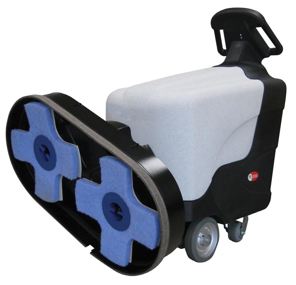
10 Machine Components Controls and Instruments Traction Pad Assist 10

11 300BU Traction Model 1. Key Switch - Turns the machine on/off. 2. Handle Lever - When the lever is engaged the machine will move forward. If the Burnish switch is on, the pad will also start turning. If the burnish head is tilted up into the pad change position, the burnish motor will not engage. NOTE: The machine needs to be moving when the burnish switch is turned on or off in order to keep from burning the floor. 3. Burnish Switch - Turns burnish function on/off. The burnish motor will not engage unless the burnish switch is on and the handle lever is engaged. If the burnish head is tilted up into the pad change position, the burnish motor will not engage. 4. Reverse Switch - Hold down this switch while the handle lever is engaged and the machine will move in reverse. Once the reverse switch is released the machine will start moving forward. 5. Traction Speed Control - Turn the knob clockwise to increase speed. Turn the knob counter-clockwise to decrease speed. 6. Hour Meter / Battery Discharge Indicator - The LCD displays the number of burnishing hours. The machine will only count hours while burnishing. The row of LEDs display the charge level of the battery pack. When all the yellow LEDs are lit, the battery pack is fully charged. In order to protect the battery pack, when the red LED is lit, the burnish motor will stop and the machine should be recharged. 7. Alarm LED - Displays trouble codes as a blink pattern. In normal operation this LED will be off. If it comes on, refer to the troubleshooting section. 300BU Pad Assist Model 1. Key Switch - Turns the machine on/off. 2. Handle Lever - When the lever is engaged, if the burnish switch is on, the pad will start turning. If the burnish head is tilted up into the pad change position, the burnish motor will not engage. NOTE: The machine needs to be moving when the burnish switch is turned on or off in order to keep from burning the floor. 3. Burnish Switch - Turns burnish function on/off. The burnish motor will not engage unless the burnish switch is on and the handle lever is engaged. If the burnish head is tilted up into the pad change position, the burnish motor will not engage. 4. Hour Meter / Battery Discharge Indicator - The LCD displays the number of burnishing hours. The machine will only count hours while burnishing. The row of LEDs display the charge level of the battery pack. When all the yellow LEDs are lit the battery pack is fully charged. In order to protect the battery pack, when the red LED is lit the burnish motor will stop and the machine should be recharged. Over Current Protection 1. 70A Breaker - Over current protection for the burnish motor. Push to reset A Breaker - Over current protection for the traction drive. Push to reset (Only on Traction models). 3. 3A Fuse In-Line holder - Over current protection for key switch. 11
. If the level is low, add just enough distilled water to cover the plates.")
12 Onboard Battery Charger To charge the batteries, first drive the machine to a flat, dry, well-ventilated area then turn the machine off. If using lead acid batteries, check the water level in all the battery cells (see Battery Maintenance section). If the level is low, add just enough distilled water to cover the plates. **DO NOT OVERFILL!** Battery Charger Controls 1. Three-digit display + symbol (1), to view A=charging current, U=battery voltage, h=charging time, C=charging ampere-hours (AH), E=energy used to charge (KWh) 2. Button for the Selection of the display mode (2): A, U, h, C, E. After 10 seconds the display returns to the display of charging current. 3. Red control indicator (3): when it is on, the charging cycle has started. 4. Yellow control indicator (4): when it is on, the final phase of the charging cycle has started. 5. Green control indicator (5): when it is on, the charging cycle has finished. Once the charge cycle is complete, the charger will remain active in a trickle charge mode to maintain the charge on the batteries until the charger is unplugged from the wall socket. Then plug the charger cord into a wall socket. The battery charger will initialize and then soft start the charging cycle. WARNING! Batteries emit hydrogen gas when charging. Explosion or fire can result. Keep sparks and open flame away when charging. CAUTION! When servicing machine, wear protective gloves and goggles when handling batteries or battery cables. Avoid contact with battery acid. 12


13 Charger Settings The On-Board battery charger settings need to be set for your battery type before charging. Failure to properly set will result in battery damage. To determine your battery type, see battery label or contact your battery supplier. To change charger settings: 1. Unplug the charger. 2. Peel back the corner of the display label. 3. Set the DIP switches, according to your battery pack, as shown below. If your battery pack type is not listed please call Amano Pioneer Eclipse at for correct setting. Battery Charger Fault Codes Fault Description Remedy No Display a No display on the charger, no LED indicators. Incorrect battery connection or no battery connection. The maximum voltage admissible by the battery has been exceeded. The charge cycle was interrupted. The maximum temperature has been exceeded. The charge cycle was interrupted. The maximum time for the charging phase has been exceeded. The charge cycle was interrupted. The total safety time has interrupted the charge cycle. Check that the plug is connected to an operating wall outlet. Check fuse. 20A fuse MP Check the connection and the polarity of the battery connection. Restart the charge cycle. If problem persists, battery pack may be damaged. Restart the charge cycle. If problem persists, battery pack may be damaged. Restart the charge cycle. If problem persists, battery pack may be damaged. Restart the charge cycle. If problem persists, battery pack may be damaged. Internal charger fault. Replace battery charger. 13


14 How the Machine Works The Burnish components of the machine are: Burnish pad holder Burnish pad Burnish motor Dust Collection Bag As the machine moves forward, the burnish pad shines the floor. Any excess dirt or wax gets picked up by the pad and distributed into the dust collection bag via the dust collection system. Pre-Operation Checklist Before operating the machine: Check that the Burnish Switch is in the off position. Check the pad holder to ensure there are no breaks or cracks. Check correct connection of the batteries. Check that the Dust Collection Bag is empty. Release caster breaks. Turning on the Machine 1. Complete pre-operation check. 2. Turn the Key to the ON position. 3. Turn on the burnish switch and engage the handle levers. 4. Adjust speed as needed with traction speed control knob. (Traction Models Only) Changing Direction When the handle levers are engaged the machine will travel in the forward direction. To travel in reverse, while the handle levers are engaged, hold down the reverse switch. The machine will change from forward direction to reverse direction. The machine will continue in the reverse direction until the reverse switch is released. Stopping & Turning Off Machine To stop the machine, release the handle levers and the machine will smoothly break to a stop and after 3 seconds the burnish motor will stop. When turning the machine off, turn off the burnish switch and then turn off the key switch. Operation on Inclines CAUTION! When the machine is traversing on an incline, up or down, move slowly. CAUTION! Do not run burnish pad on an incline. The maximum rated climb and descent incline is 6. Installing / Changing Burnishing Pad 1. Make sure the Burnish Switch is OFF. 2. Lift on the front of the deck and tilt deck into the pad change position. 3. Remove the center device by turning counterclockwise and carefully remove the old pad from the Velcro material. CAUTION! CAREFULLY INSPECT THE PAD HOLDER FOR CRACKS OR DAMAGE! REPLACE IF NECESSARY. 4. Pull center from new pad, align pad on pad holder and secure with centering device by turning clockwise. 5. Press pad firmly onto pad holder face. 6. Lift the front of the shroud and lift the shroud release lever and SLOWLY let the shroud return to the down position. CAUTION! KEEP HOLD OF THE DECK TO AVOID INJURY! 14


15 Dust Bag Removal The machine has two dust bag options. A re-usable cloth bag and a disposable paper bag. Monitor the dust bag carefully and empty/change as needed. The dust collection system will not operate effectively when the dust bag is full. Under heavy burnishing conditions the dust bag should be emptied/changed every hour. 1. Turn off the Burnish Motor. 2. Unscrew the knobs holding the dust bag cover to the shroud. Pad Pressure Adjustment The pad pressure is set at the factory for optimal burnish performance in most conditions. If the pad pressure needs to be adjusted, follow the procedure outlined below. NOTE: Pad pressure adjustments should only be performed by a qualified technician. 1. Turn burnish switch off. 2. Remove back panel. 3. Adjust ball end to increase or decrease pad pressure as shown in diagram. 3. Pull the dust bag off the dust tube. Increase Pad Pressure Decrease Pad Pressure 4. Empty/Change dust bag. Caster Parking Brake The two rear casters are equipped with brakes. To set the brake, push down the ON side of the brake lever. To release the brake push down the OFF side of the brake lever. The caster breaks should only be used as a parking brake if needed. Before moving the machine make sure both breaks are released. Post Operation Checklist Turn the machine OFF and perform the following checks: Check for wire, string, or twine wrapped around the burnish pad. Check for frayed wires or damage. Empty the dust collection bag. Inspect batteries. Plug in on-board battery charger. 15
16 Maintenance Scheduled Maintenance Interval Operation Daily Every 25 Hrs Every 50 Hrs Every 100 Hrs Every 200 Hrs Every 500 Hrs Every 1000 Hrs Empty/Clean Dust Bag Inspect Pad Holder Inspect Battery water level (Lead Acid only) Check wiring harness for fray or cut Check for loose/missing nuts or screws Tighten nuts and screws Check brushes on transaxle motor and burnish motor Lubricate rear casters Check Burnish motor ampere draw Replace the gas shock Inspect Burnishing Head Assembly (30 ) Inspect Deck Drive Belt (30 ) Replace Drive Belt (30 ) As Required These items must be performed with the proper tools and training. Contact a Amano Pioneer Eclipse Factory Certified Technician unless you have the proper equipment and mechanical proficiency. 16
17 Body & Battery Cover The body may be cleaned with a damp cloth to remove dust and scuff marks. More stubborn scuff marks on the tank exterior can be removed with a vinyl cleaner Battery Maintenance The batteries are deep cycle 12 volt batteries. The lifetime of the batteries is limited by the number of charges the batteries receive. To get the most life from the batteries, charge them when the battery discharge LED (Red) starts to blink (20% charge left). Use only the on-board battery charger supplied to charge the batteries. Periodically clean the top surface of the batteries and the terminals, and check for loose connections. Use a strong solution of baking soda and water. Brush the solution sparingly over the battery tops, terminals, and cable clamps. CAUTION! DO NOT ALLOW ANY BAKING SODA SOLUTION TO ENTER THE BATTERIES! Use a wire brush to clean the terminal posts and cable connectors. After cleaning, apply a coating of clear battery post protectant to the terminals and the cable connectors. Keep the tops of the batteries clean and dry. To prevent a possible short circuit, keep all metallic objects off the top of the batteries. Replace any worn or damaged wires. Lead Acid Batteries Sealed batteries no additional maintenance required. CAUTION! When working with batteries, always wear eye protection and protective clothing. CAUTION! Batteries emit hydrogen gas. NO SMOKING! Never add acid to the batteries, only distilled water. Always keep the battery caps on, except when adding water or taking hydrometer readings. CAUTION! Never use tap water to fill battery cells. Tap water contains contaminants that will damage the battery. Only use distilled water to fill battery cells. Check the electrolyte level in each battery cell before and after charging, and after every 50 hours of operation. Do not charge the batteries unless the fluid is slightly above the battery plates. If needed, add just enough distilled water to cover the plates. Never add acid to the batteries. CAUTION! DO NOT OVERFILL! Measuring the specific gravity, using a hydrometer, is a way to determine the charge level and condition of the batteries. If one or more of the battery cells test lower than the other battery cell (0.050 or more), the cell is damaged, shorted, or is about to fail. CAUTION! Battery damage will occur if the electrolyte level does not cover the battery plates. CAUTION! Machine and/or battery damage can occur if the electrolyte level is above the bottom of the tube in each cell. 17

 1. Push machine to level surface. 2.")
18 Rear Casters Each of the two rear casters has two grease fittings. Lubricate each caster with a grease gun every 100 hours of machine operation Part No: MP Belt Replacement 1. Place a 9/16 wrench on the bolt of the tensioner idler pulley and rotate the tensioner downward. 2. With the tension removed, remove the belt from the tensioner pulley. 3. Slowly allow the tensioner to rotate to a natural position. 4. Remove the belt from the deck. 5. With belt removed, inspect all of the fasteners for proper tightness. Also check the bearings for wear and the condition of each pulley. 6. Install the new belt using the belt diagram. Belt Maintenance (30 Models) 1. Push machine to level surface. 2. Turn machine off and disconnect the battery pack. 3. Lift up on the front of the deck, placing the deck in the pad change position. 4. Remove the pad retainer and pads from the pad holders. 5. Remove the pad holders from each of the drive pulleys, by removing the (4) bolts in the center of the pad holder. 6. Locate and remove the (4) bolts that fasten the pulley cover to the deck. 7. Rotate the deck belt. If there are excessive cracks in the belt ribs and chunks that have broken off the ribs, the belt needs to be replaced. 7. Use a 9/16 wrench to rotate the tensioner down so the new belt can be installed. 8. Slowly allow the tensioner to tighten against the belt. 9. Turn the belt through several revolutions to make sure the belt tracks properly. 10. Reinstall the pulley cover. 11. Reinstall the pad holders on to the drive pulleys. 12. Turn the pad holders to verify that there is no interference. 13. Install pads onto the pad holders. 14. Slowly lower the deck back to the operating position. 18
19 Alarm Codes (Traction Only) *Given the following alarm codes, troubleshooting should only be done by a Amano Pioneer Eclipse Factory Certified Technician. A programming handset may be required for troubleshooting. Number of Flashes Description Possible Cause 1 (fast) Low Battery Voltage The battery needs charging or there is a bad connection to the battery. Check the connections to the battery. If the connections are good, try charging the battery. 1 (medium) Handle lever engaged at key on Disengage the handle lever, key off and key back on to clear 1 (slow) Machine Time Out 2 Motor Disconnected 3 Motor Wiring Trip 6 Inhibit Active 7 Throttle Trip 8 Possible Controller Trip 9 Solenoid Brake Trip 10 High Battery Voltage The machine has been left with the key on. Turn the key off and then back on again. The motor has a bad connection. Check all the connections and leads between the motor and the controller. The motor has a short circuit to a battery. Check all the connections and leads between the motor and the battery. The controller is being inhibited from driving. Check the state of the Inhibit unputs. A throttle trip is indicated. Make sure that the throttle is in the rest position before switching on the vehicle. A possible controller trip is indicated. Make sure that all connections are secure. The parking brakes have a bad connection. Check the parking brake and motor connections. Make sure the controller connections are secure. An excessive voltage has been applied to the controller. This is usually caused by a poor battery connection. Check the battery connections. 19
20 Machine Troubleshooting Problem Possible Cause Remedy Machine will not turn on Burnish motor will not start Red LED Flashing on Dash Machine exhibits poor burnishing performance Machine exhibits very aggressive burnish performance Breaker Tripped Incorrect battery connection On-board battery charger plugged in Key switch failure Failed Fuse Deck tilted into pad change position Speed control knob turned all the way counterclockwise (off) Burnish switch off Handle levers not engaged 70A breaker tripped Battery lockout Check alarm code reference sheet Pad dirty Incorrect pad Pad worn down Gas Spring faulty Incorrect pad Push breaker button to reset Check batteries are wired together correctly via the battery connection diagram, check the Anderson connectors are plugged together Unplug the charging cord from the machine Check key switch is functioning and wiring to the key switch is correct Check the fuse in the in line fuse holder. Lower the deck to the burnish position Turn speed control knob clockwise to increase speed Turn on burnish switch Engage handle levers Push 70A breaker to reset. DO NOT use round pads on the PE300BU30X. Using round pads will shorten the run time and trip the breaker. The use of round pads on this machine will damage the burnish motor and void the warranty. Batteries need to be charged Troubleshoot accordingly Remove debris or string/twine from pads; clean pad; replace pad Use more aggressive burnishing pad Replace pad Check ampere draw of burnish motor (should not be above 50 amps); replace gas spring Use less aggressive burnishing pad Dust collection not working properly Dust collection bad, is not collecting dust Skirt is not sealing to the floor Empty dust bag Check the dust tube to see if there is an obstruction Skirt is bent or damaged. Replace if necessary. Adjust the skirt to fit tightly against the seal, but still able to move freely Check wear edge on bottom of the skirt and replace if necessary (30 ) Smell of burnt rubber Belt out of adjustment Check the automatic tensioner 20
21 Voltage: Sound Level: 36VDC (Qty. 3-12VDC Batteries) < 70 db(a) Machine Specifications Vibration: Less than 2.5 m/s 2 Forward Speed: 3.25 mph (5.23 km/h) Traction Only Reverse Speed: 1.5 mph (2.4 km/h) Traction Only Burnish Motor: 2.5 hp (1.86 kw) Permanent Magnet Transaxle:.25 hp (186 watts) Traction Only Battery Charger: 36V 25A On-Board Wheels: 8 in. (20.3 cm) Solid Battery: 12VDC Lead Acid 228 Ah (Qty. 3) Weight 126 lbs (57 kg) each - Total Battery Weight 378 lbs (171.5 kg) 12VDC AGM 235 Ah (Qty. 3) Weight 140 lbs (63.5 kg) each - Total Battery Weight 418 lbs (189.6 kg) 20 Machines 24 Machines Pad Size: 20 (51 cm) Pad Size: 24 (61.0 cm) Pad Speed: 2000 RPM Deck Width: 22 (56 cm) Pad Speed: 1800 RPM Deck Width: 26 (66 cm) Length: 49 (124 cm) Head Up Length: 49 (124 cm) Head Up 58 (147 cm) Head Down 61 (155 cm) Head Down Height: 45 (114 cm) Height: 45 (114 cm) Weight: w/o Batteries Weight: w/o Batteries 200 lbs (91 kg) Pad-Assist 212 lbs (96 kg) Pad-Assist 219 lbs (99 kg) Traction 231 lbs (105 kg) Traction 30 Machines Pad Size: 16 (41 cm) Qty. 2 Pad Speed: 2000 RPM Deck Width: 33 (84 cm) Length: Height: Weight: 51 (130 cm) Head Up 60 (152 cm) Head Down 45 (114 cm) w/o Batteries 245 lbs (111 kg) Traction 21
22 22
23 PE300BU Battery Burnisher Parts Manual Notes: 23
24 Electrical Schematic - Pad Assist 24
25 Electrical Schematic - Traction 25
26 Connections - Pad Assist 26
27 Connections - Pad Assist (Continued) Item Ref. No. Description Qty A MP HARNESS, MAIN, PAD ASSIST 1 B MP HARNESS, C.PANEL, PAD ASST. 1 C MP HARNESS, MOTOR, BURNISH 1 D MP HARNESS, SWITCH, TILT 1 E MP CABLE, BATTERY, SOLENOID 1 F1 MP MOTOR, 2000 RPM, ASM. (20 /30 ) 1 F2 MP MOTOR, 1800 RPM, ASM. (24 ) 1 G MP BREAKER, CIRCUIT, 70A 1 H MP SOLENOID, 36VDC, SPNO 1 I MP FUSE, 3A, GLASS 1 J1 SA CHARGER, 110V, 36V, ASM. 1 J2 SA CHARGER, 220V, 36V, ASM. 1 Item Ref. No. Description Qty K MP CABLE, BATTERY, w/ PLUG 1 L MP CABLE, BATTERY, M MP CABLE, BATTERY 1 N1 MP BATTERY, 12V, LEAD ACID 3 N2 MP BATTERY, 12V, SEALED 3 O MP SWITCH, MICRO, 12V 1 P MP WIRE, SWITCH, 3 1 Q MP WIRE, DIODE, ASM. 1 R MP DIODE, 6A, ASM. 1 27
28 Connections - Traction 28
29 Connections - Traction (Continued) Item Ref. No. Description Qty A MP HARNESS, MAIN, TRACTION 1 B MP HARNESS, C.PANEL, TRACTION 1 C MP HARNESS, MOTOR, BURNISH 1 D MP HARNESS, SWITCH, TILT 1 E MP CABLE, BATTERY, SOLENOID 1 F1 MP MOTOR, 2000 RPM, ASM. (20 /30 ) 1 F2 MP MOTOR, 1800 RPM, ASM. (24 ) 1 G MP BREAKER, CIRCUIT, 70A 1 H MP SOLENOID, 36VDC, SPNO 1 I MP FUSE, 3A, GLASS 1 J1 SA CHARGER, 110V, 36V, ASM. 1 J2 SA CHARGER, 220V, 36V, ASM. 1 K MP CABLE, BATTERY, w/ PLUG 1 L MP CABLE, BATTERY, Item Ref. No. Description Qty M MP CABLE, BATTERY 1 N1 MP BATTERY, 12V, LEAD ACID 3 N2 MP BATTERY, 12V, SEALED 3 O MP HARNESS, WIRING, TR. AXLE 1 P MP TRANSAXLE, 36V, ASM. 1 Q MP CONTROLLER, TRACTION 1 R MP BREAKER, CIRCUIT, 40A 1 S MP DIODE, 6A, ASM. 1 T SA LED, RED, REPLACEMENT 1 U MP SWITCH, MICRO, 12V 1 V MP WIRE, 10AWG, RED, 3 L 1 W MP WIRE, 10AWG, REG, 16 L 1 X MP WIRE, 10AWG, BLK, 12 L 1 29
30 Skirt, Deck & Axle Bracket Assembly RF
31 Skirt, Deck & Axle Bracket Assembly (continued) Item Ref. No. Description Qty 1A MP SKIRT, 20, ASM. 1 1B MP SKIRT, 24, ASM. 1 2 NB BOLT, HEX, 1/4 X 2-1/2 1 3 NB3350 WASHER, FLAT, 1/4 2 4 MX1045 NUT, HEX, 1/4 1 5A MP EDGING, WEAR, SKIRT (20 ) 6 FT 5B MP EDGING, WEAR, SKIRT (24 ) 7 FT 6 MP6600 FELT, VELCRO, BLK, 2 2 (4 ) 7 MP BRACKET, AXLE / TRANSAXLE 1 8 MP TUBE, MOUNT, SHROUD 1 9 MP BUSHING, FLANGED, 1/ NB PIN, CLEVIS, 1/2 X 4-1/ NB PIN, PRESTO, 3/32 X 1-5/ MP BALL, STUD, 10MM 1 13A NB BOLT, HEX, 1/2 X 1-1/2 (20 ) 1 13B NB BOLT, HEX, 7/16 X 1-1/2 (24 / 30 ) 1 Item Ref. No. Description Qty 14A NB NUT, LOCK, 1/2 (20 ) 1 14B NB NUT, LOCK, 7/16 (24 ) 1 15 N/A N/A - 16A MP SHROUD, 20, ASM. 1 16B MP SHROUD, 24, ASM MP BUSHING, FLANGED, 1/ MP SWITCH, MICRO, 12V 1 19 NB9625 SCREW, #4 X 3/ NB NUT, LOCK, # NB GROMMET, 2 ID 1 22A MP FELT, VELCRO, BLK, 1 (20 ) 6 FT 22B MP FELT, VELCRO, BLK, 1 (24 ) 7 FT 23A MP MOTOR, 2000 RPM, ASM. (20 /30 ) 1 23B MP MOTOR, 1800 RPM, ASM. (24 ) 1 24 NB6851 BOLT, HEX, 3/8 X 3/ MX1075 WASHER, LOCK, 3/8 4 31
32 Main Bottom Assembly - Pad Assist RF
33 Item Ref. No. Description Qty 1A MP BRACKET, AXLE, ASM. (20 ) 1 1B MP BRACKET, AXLE, ASM. (24 ) 1 2 MP CASTER, 4, w/ BRAKE 2 3 NB9267 WASHER, FLAT, 5/ NB6111 WASHER, LOCK, 5/ NB9745 BOLT, HEX, 5/16 X 3/ NB3350 WASHER, FLAT, 1/4 4 7 MP WHEEL, 8 X MP AXLE 1 9 NB BOLT, U, 1/ MP SPACER, AXLE 2 11 NB3275 NUT, LOCK, 1/4 4 Main Bottom Assembly - Pad-Assist (continued) 33
34 Main Bottom Assembly - Traction RF
35 Item Ref. No. Description Qty 1A MP BRACKET, AXLE, ASM. (20 ) 1 1B MP BRACKET, AXLE, ASM. (24 ) 1 2 MP TRANSAXLE, 36V, ASM. 1 3 PG BRACKET, TRANSAXLE 2 4 NB6545 BOLT, HEX, 5/16 X NB3265 NUT, LOCK, 5/ BA KEY, 3/16 X 1-1/2 2 7 NB RING, RETAINING, 3/4 2 8 MP WHEEL, 8 X NB9302 SCREW, SET, 1/4 X 3/ NB9505 WASHER, FLAT, 5/16 X 1-1/ MP CASTER, 4, w/ BRAKE 2 12 NB9267 WASHER, FLAT, 5/ NB6111 WASHER, LOCK, 5/ NB9745 BOLT, HEX, 5/16 X 3/4 14 Main Bottom Assembly - Traction (continued) 35
36 Main Rear Assembly RF
37 Main Rear Assembly (continued) Item Ref. No. Description Qty 1 MP PLATE, MOUNT, SHOCK 1 2 MP BALL, STUD, 10MM 1 3 NB3265 NUT, LOCK, 5/16 1 4A MP SPRING, GAS (20 ) 1 4B MP SPRING, GAS (24 ) 1 4C MP SPRING, GAS (30 ) 1 5 NB9267 WASHER, FLAT, 5/ NB6111 WASHER, LOCK, 5/ NB9745 BOLT, HEX, 5/16 X 3/4 9 8 NB NUT, JAM, 5/ NB NUT, KEPS, # A SA CHARGER, 110V, 36V, ASM. 1 10B SA CHARGER, 220V, 36V, ASM. 1 Item Ref. No. Description Qty 11 MP PLATE, MOUNT, CHARGER 1 12 NB6035 TIE, CABLE, 1/8 X NB SCREW, PH, #10 X 3/ NB NUT, KEPS, # MP PLATE, MOUNT, SOLENOID 1 16 MP SOLENOID, 36VDC, SPNO 1 17 NB6535 BOLT, HEX, 1/4 X 3/ NB9845 NUT, KEPS, 1/ MP CONTROLLER, TRACTION 1 20 MX1011 SCREW, #8 X 1-1/4 (TRACTION) 2 21 NB9710 NUT, KEPS, #8 (TRACTION) 2 37
38 Main Top Assembly RF
39 Main Top Assembly (continued) Item Ref. No. Description Qty 1 MP LEVER, HANDLE, LEFT 1 2 MP LEVER, HANDLE, RIGHT 1 3 NB6390 PIN, ROLL, 1/4 X 1-1/8 2 4 MP PLATE, COVER, REAR 1 5 NB9267 WASHER, FLAT, 5/ NB6111 WASHER, LOCK, 5/ NB9745 BOLT, HEX, 5/16 X 3/4 4 8 NB9710 NUT, KEPS, #8 2 9 NB SCREW, PH, #8 X 3/ MP COVER, VINYL 2 11 NB SCREW, PH, #8 X 3/ MP SPRING, LEVER, HANDLE 1 13 MX1025 SCREW, PH, #10 X 3/ NB9510 NUT, FLANGE, # MP PANEL, CONTROL, TRACTION 1 16 MP DECAL, C.PANEL, TRACTION 1 Item Ref. No. Description Qty 17 MP METER, HOUR / BATTERY 1 18 MP SWITCH, ROCKER, DPST 1 19A MP SWITCH, 36V 1 19B KC KEY, SWITCH (NOT SHOWN) 1 20 MP SWITCH, PUSH (TRACTION) 1 21 PG POTENTIOMETER (TRACTION) 1 22 MP KNOB (TRACTION) 1 23 MP SWITCH, MICRO, 12V 1 24 NB SCREW, #4 X NB NUT, LOCK, # SA LED, RED, 36V 1 27 MP PANEL, CONTROL, PAD ASSIST 1 28 MP DECAL, C.PANEL, PAD ASSIST 1 29 NB9625 SCREW, #4 X 3/ MP MOLDING, TRIM 16 39
40 Main Front Assembly * RF
41 Main Front Assembly (continued) Item Ref. No. Description Qty 1 NB PIN, CLEVIS, 1/2 X 4-1/2 1 2 NB PIN, PRESTO, 3/32 X 1-5/8 1 3 MP LATCH, TILT 1 4 NB BOLT, SHLD, 3/8 X 1/2 1 5 NB BOLT, SHLD, 3/8 X 3-1/2 1 6 NB3265 NUT, LOCK, 5/16 2 7A MP PAD HOLDER, B MP PAD HOLDER, C MP RETAINER, PAD (NOT SHOWN) 1 8 NB WASHER, FLAT, 3/4 1 9 N/A N/A - 10 NB9505 WASHER, FLAT, 5/16 X 1-1/2 1 11A MP SKIRT, 20, ASM. 1 11B MP SKIRT, 24, ASM MP BAG, DUST, CLOTH 1 13 MP BAG, DUST, PAPER 1 14 MP COVER, BAG, DUST 1 15 MP KNOB, 1/4 X 3/ MP RETAINER, BATTERY 1 17A MP SPRING, COMP.,.90 ID (20 ) 1 17B MP SPRING, COMP.,.81 ID (24 ) 1 17C MP SPRING, COMP.,.83 ID (30 ) 1 Item Ref. No. Description Qty 18 NB9267 WASHER, FLAT, 5/ NB6111 WASHER, LOCK, 5/ NB9745 BOLT, HEX, 5/16 X 3/ NB WASHER, FLAT, 3/ NB3350 WASHER, FLAT, 1/ NB6110 WASHER, LOCK, 1/ NB6530 BOLT, HEX, 1/4 X MP8300 HOOK, VELCRO, MP FILTER, DUST, MOTOR 1 27 MP COVER, BATTERY, ASM MP PLATE, MOUNT, PLUG 1 29 MP BREAKER, CIRCUIT, 70A 1 30 MP BREAKER, CIRCUIT, 40A (TRAC.) 1 31 MP CABLE, BATTERY, SOLENOID 1 32 NB6535 BOLT, HEX, 1/4 X 3/ NB9845 NUT, KEPS, 1/ NB9000 BOLT, HEX, 1/4 X 1-1/2 2 41
42 30 Deck Assembly 42 RF
43 30 Deck Assembly (continued) Item Ref. No. Description Qty 1 MP SHROUD, 30, ASM. 1 2 MP BUSHING, FLANGED, 1/2 2 3 MP SWITCH, MICRO, 12V 1 4 NB9625 SCREW, #4 X 3/4 2 5 NB NUT, LOCK, #4 2 6 MP MOTOR, 2000 RPM, ASM. 1 7 BA KEY, 3/16 X MX1075 WASHER, LOCK, 3/8 9 9 NB6851 BOLT, HEX, 3/8 X 3/ NB WASHER, FLAT, 3/ MP PULLEY, NB9505 WASHER, FLAT, 5/16 X 1-1/ NB6111 WASHER, FLAT, 5/ NB9745 BOLT, HEX, 5/16 X 3/ NB1588 BOLT, HEX, 3/8 X 2-1/ MP SPACER, PULLEY 2 17 MP PULLEY, 4, ASM NB3450 WASHER, FLAT, 3/ NB NUT, HEX, 3/ NB BOLT, CARRIAGE, 3/8 X 2 2 Item Ref. No. Description Qty 21 MP IDLER, FLAT, MP TENSIONER, BELT, ASM NB6042 BOLT, HEX, 3/8 X MP BELT, K MP PAD HOLDER, 16, ASM NB6110 WASHER, LOCK, 1/ NB6530 BOLT, HEX, 1/4 X MP COVER, BELT, ASM NB SCREW, BH, 1/4 X 3/ NB3350 WASHER, FLAT, 1/ MX1045 NUT, HEX, 1/ MP FELT, VELCRO, MP SEAL, TRIM, w/ BULB NB WASHER, FLAT, 3/8 X 1-1/ MP PAD HOLDER, MP RETAINER, PAD 1 37 NB SCREW, #10 X 1/ MP PLATE, PAD HOLDER, ADAPTER 1 39 NB SCREW, SH, 1/4 X 3/4 6 43
44 30 Skirt, Pulley & Tensioner Assembly 1A B 2 1A 1B RF
45 30 Skirt, Pulley & Tensioner Assembly (continued) Item Ref. No. Description Qty 1A MP SKIRT, 30, ASM. (w/ FELT) 1 1B MP SKIRT, 30, ASM. (w/ EDGING) 1 2 NB BOLT, HEX, 1/4 X 2-1/2 1 3 NB3350 WASHER, FLAT, 1/4 2 4 MX1045 NUT, HEX, 1/4 1 5 MP8300 HOOK, VELCRO, MP MOLDING, BLK 90 7 MP EDGE, WEAR, FELT 1 8 MP DOT, FELT 4 9 MP WASHER, RUBBER 2 10 MP EDGING, WEAR NB RIVET, 1/8 X 5/ NB WASHER, FLAT, #4 12 Item Ref. No. Description Qty 13 MP BODY, TENSIONER 1 14 MP PLATE, EXT., TENSIONER 1 15 MP PLATE, MOUNT, TENSIONER 2 16 MP IDLER, FLAT, 3.24 X NB3450 WASHER, FLAT, 3/ MX1075 WASHER, LOCK, 3/ NB BOLT, HEX, 3/8 X 1-1/ NB6111 WASHER, LOCK, 5/ NB BOLT, HEX, 5/16 X 1-1/ MP PULLEY, MP BEARING, NB RING, RETAINING, 40MM 2 45
46 Limited Warranty PE300BU TO QUALIFY FOR THIS WARRANTY (1) Machine must be registered at the time of purchase on a form provided by Amano Pioneer Eclipse Corporation. Your Amano Pioneer Eclipse Distributor is responsible for the registration of your machine. Please cooperate with your Distributor in supplying necessary information on the card. (2) The machine must have been purchased from Amano Pioneer Eclipse Corporation or an authorized Amano Pioneer Eclipse Distributor. (3) This warranty extends to the original purchaser only and is not transferable to subsequent owners. TIME PERIODS (1) Rotational molded parts are warranted for eight (8) years. (2) Batteries warranted by battery manufacturer for one (1) year. (3) THREE (3) YEAR WARRANTY - For parts on the PE300BU. Warranted to be free from defects in material and workmanship for a period of three (3) years from the date of purchase by the original owners. (See Exclusions) (4) ONE (1) YEAR WARRANTY - For labor necessary to make warranty repairs. EXCLUSIONS (Not Covered by Warranty) (1) Parts that fail through normal wear by reason of their characteristics (cords, pads, belts, skirt, wheels, pad holder, or other consumable parts). (2) This warranty does not extend to parts affected by misuse, neglect, abuse or improper maintenance. All defective parts must be returned to the distributor for credit. THE OBLIGATION OF AMANO PIONEER ECLIPSE CORPORATION (1) The obligation of Amano Pioneer Eclipse under this warranty is limited to repairing or replacing, at its option, any part which is proven to be defective in material or workmanship under normal use for the applicable period stated above. (2) Warranty repairs will be made by your Amano Pioneer Eclipse Distributor without charge for parts and labor. They will be compensated with a warranty labor rate of $45.00 per hour, for the first year of ownership. (3) Parts repaired or replaced under this warranty are warranted only during the balance of the original warranty period. All defective parts replaced under these warranties become the property of Amano Pioneer Eclipse. WARRANTY SERVICE To obtain warranty service, take your machine and proof of purchase to any authorized Amano Pioneer Eclipse Distributor. Amano Pioneer Eclipse will not reimburse expenses for service calls or travel. For the Distributor in your area, call Amano Pioneer Eclipse Customer Service Department at or If you are dissatisfied with the service that you receive, call or write Amano Pioneer Eclipse Customer Service Department for further assistance. INSTRUCTIONS AND CONDITIONS FOR WARRANTY REIMBURSEMENT Order replacement part: Orders will be processed and charged, as normal procedure. Call Amano Pioneer Eclipse for R/A number. You will need the Machine Serial Number and the Machine Model Number. Parts must be returned, accompanied with the R/A number to be eligible for warranty credit. All Warranty Parts will be shipped prepaid UPS Ground, any other method will be at the recipients expense. Freight on any Warranty Part after 30 days must be paid for by the Purchaser. Warranty labor rate is $45.00 per hour. Credit will be issued upon completion of the above steps, at the above rates. DISCLAIMER OF CONSEQUENTIAL AMANO PIONEER ECLIPSE DISCLAIMS ANY RESPONSIBILITY FOR LOSS OF USER TIME OF THE AMANO PIONEER ECLIPSE MACHINE OR ANY OTHER INCIDENTAL OR CONSEQUENTIAL DAMAGE EXCEPT AS STATED IN THE WARRANTY APPLICABLE TO EACH MACHINE. EXCEPT AS STATED IN SUCH WARRANTIES, THE COMPANY DOES NOT OTHERWISE WARRANT ANY MACHINE AND NO WARRANTY, EXPRESS, IMPLIED OR STATUTORY IS MADE BY THE COMPANY. Copyright 2016 Amano Pioneer Eclipse Corporation LT063500_F;
OPERATIONS MANUAL. Battery Burnisher
 OPERATIONS MANUAL Battery Burnisher BB20N 20 Non-Traction drive BB20T 20 Traction Drive BB24T 24 Traction Drive IPC Eagle 3650 Dodd Rd, Eagan MN 55123 800.486.2775 www.ipceagle.com 1 Instructions For Use
Lumina 28 Traction Drive Model: Battery Burnisher M28036TDQP OPERATION SERVICE PARTS CARE
 Lumina 28 Traction Drive Model: Battery Burnisher M28036TDQP OPERATION SERVICE PARTS CARE Table of Contents IMPORTANT SAFETY INSTRUCTIONS...1 OPERATING INSTRUCTIONS...2 INSPECTION...2 ELECTRICAL...2 BATTERIES...2
AUTOMATIC BURNISHER MODEL FURY 21 HSB
 AUTOMATIC BURNISHER MODEL FURY 21 HSB INTRODUCTION OPERATING & MAINTENANCE INSTRUCTIONS This operator s book has important information for the use and safe operation of this machine. Read this book carefully
NILFISK BA 500 Service Manual
 NILFISK BA 500 Service Manual Model 66324400 12/94 Form Number 043023 TABLE OF CONTENTS Batteries...21 Brush Drive Belt Adjustment Or Replacement...7 Brush Drive Motor - Carbon brush Inspection... 8 Brush
FLOORMASTER 18B OPERATING & MAINTENANCE READ THIS BOOK
 FLOORMASTER 18B INTRODUCTION OPERATING & MAINTENANCE INSTRUCTIONS This operator s book has important information for the use and safe operation of this machine. Read this book carefully before starting
1250 LB. CAPACITY MECHANICAL WHEEL DOLLY
 1250 LB. CAPACITY MECHANICAL WHEEL DOLLY 67287 SET-UP AND OPERATING INSTRUCTIONS Visit our website at: http://www.harborfreight.com Read this material before using this product. Failure to do so can result
S10 PEDESTRIAN SWEEPER OPERATOR MANUAL
 S10 PEDESTRIAN SWEEPER OPERATOR MANUAL Clemas & Co. Unit 5 Ashchurch Business Centre, Alexandra Way, Tewkesbury, Gloucestershire, GL20 8NB. Tel: 01684 850777 Fax: 01684 850707 Email: info@clemas.co.uk
PE310AS Operator s Manual
 Walk-Behind Autoscrubber PE310AS Operator s Manual Instructions For Use Failure to read and understand this manual before operating this machine or performing service on this machine may result in injury
OBAE, OBAEXU, ON BOARD Battery Chargers
 C O R P O R A T IO N O P E R A T I N G I N S T R U C T I O N S OBAE, OBAEXU, ON BOARD Battery Chargers INTRODUCTION: The OBAE line of chargers are designed for the permanent installation on battery powered
SpeedGleam /Plus. 36 Volt Dust Control Burnisher. Operator and Parts Manual
 SpeedGleam /Plus 36 Volt Dust Control Burnisher Model No.: 608525 SpeedGleam 608526 SpeedGleam Pac. 609251 SpeedGleam Pac. Can. 608344 SpeedGleam Plus 608345 SpeedGleam Plus Pac. 609252 SpeedGleam Plus
Installation Operation Parts
 OWNER S MANUAL BATTERY BACKUP SUMP Installation Operation Parts For further operating, installation or maintenance assistance, Call 98-8-05 PRINTED IN U.S.A. M-8 (/9) RULES FOR SAFE INSTALLATION AND OPERATION
TO ORDER PARTS CALL: (479) or
 or") Owner s Manual Industrial Ergonomic User-Friendly Hand Controls Date Manufactured: / / o Mart Cart XTi 24 Model 03522 - SKU# 280-3522 o Mart Cart XTi 24 Model 03524 - SKU# 280-3524 CONGRATULATIONS You
Owner s Manual Industrial Ergonomic User-Friendly Hand Controls Date Manufactured: / / o Mart Cart XTi 24 Model 03522 - SKU# 280-3522 o Mart Cart XTi 24 Model 03524 - SKU# 280-3524 CONGRATULATIONS You
CREWMAN. Dust Control 20 Battery Burnisher. Operator and Parts Manual E
 E8563-00 CREWMAN Dust Control 0 Battery Burnisher Operator and Parts Manual 00 Brown Avenue Toledo, Ohio 43607-07 Customer Service: 888-GO-BETCO Fax: 800-445-5056 Technical Service: 877-856-5954 www.betco.com
HSB21 Battery Burnisher
 HSB21 Battery Burnisher OPERATION AND PARTS MANUAL Rev A 01/2003 HS2100 PARTS LIST Item No. Qty Part No. Description 1 1 001 Lower Body Housing 2 1 002 Battery Condition Meter 3 1 003 RPM Meter 4 1 004
24 VOLT AUTOMATIC BATTERY CHARGER PART NO
 24 VOLT AUTOMATIC BATTERY CHARGER PART NO. 957732 AC Input: DC Output: Battery Type: Specifications 230 volts, 50 hertz, 3.5 amps, single-phase 24 volts, 20 amps initially tapering to 6 amps 24 volt, 12
OBE, OBEXU, ON BOARD Battery Chargers
 C O R P O R A T IO N O P E R A T I N G I N S T R U C T I O N S OBE, OBEXU, ON BOARD Battery Chargers INTRODUCTION: These chargers are designed for the permanent installation on battery powered vehicles
OWNER S MANUAL and TECHNICAL DOCUMENTATION
 IMPORTANT DOCUMENT - DELIVER TO MANAGER Quality, Performance, Value OWNER S MANUAL and TECHNICAL DOCUMENTATION MODELS 280-4036, 280-4037, 280-4063 FOR UL (Underwriter Laboratories) APPROVED CARTS Mart
(Electric) Sweeper English EN Operator Manual Rev. 08 ( ) *330569*
 Sweeper English EN Operator Manual Rev. 08 ( ) *330569*") 3640 (Electric) Sweeper English EN Operator Manual www.tennantco.com 330569 Rev. 08 (02-2008) *330569* This manual is furnished with each new model. It provides necessary operation and maintenance instructions.
3640 (Electric) Sweeper English EN Operator Manual www.tennantco.com 330569 Rev. 08 (02-2008) *330569* This manual is furnished with each new model. It provides necessary operation and maintenance instructions.
QPET, QPETXU Battery Chargers
 C O R P O R A T IO N O P E R A T I N G I N S T R U C T I O N S QPET, QPETXU Battery Chargers INTRODUCTION: The QPET line of chargers are designed for general purpose deep cycle batteries. They are an electronically
Cruising Charger Series OWNER S MANUAL
 R Cruising Charger Series OWNER S MANUAL ON BOARD BATTERY CHARGERS Models DC Amperage No. Of Banks Volts 2614A 5,10 Amps 2 Bank 12/12 2614A-230 2621A 5,5,10 Amps 3 Banks 12/12/12 2621A-230 2622A 10,10
Hydraulic Transmission Jacks
 Hydraulic Transmission Jacks Operating Instructions & Parts Manual Model Number Atd-7435 Atd-7436 Atd-7437 Capacity 1100 Lb. 2000 Lb. 3000 Lb. Model Atd-7435 Model Atd-7436 Model Atd-7437 Atd Tools Inc.
ATV TRACK KIT. Operator s Manual Installation Instructions Service Instructions Replacement Parts List. Effective Date: October, 2012
 p/n 2258-642 ATV TRACK KIT Operator s Manual Installation Instructions Service Instructions Replacement Parts List Track Assembly Kits (p/n 1436-204) Mounting Assembly Kits (p/n 1436-205) 1436-815) Effective
Heavy Duty Engine Cranes
 Heavy Duty Engine Cranes Operating Instructions & Parts Manual Model Number Atd-7484 Atd-7485 (Foldable Legs) Capacity 2 Ton 2 Ton Model Atd-7484 Model Atd-7485 Atd Tools Inc. 160 Enterprise Drive, Wentzville,
NSS HIGH-SPEED BATTERY BURNISHERS
 OPERATION MANUAL NSS HIGH-SPEED BATTERY BURNISHERS IMPORTANT SAFETY INSTRUCTIONS WARNING: Failure to observe these instructions can cause personal injury to machine operator or bystanders. WARNING: Fire
ACCUSENSE CHARGE SERIES ON/OFF BOARD FULLY AUTOMATIC BATTERY CHARGER
 ACCUSENSE CHARGE SERIES ON/OFF BOARD FULLY AUTOMATIC BATTERY CHARGER SPECIFICATIONS: *Photo for reference only* Part number 8890439 Mode Select: Selects Battery Type Refer to Section 6. IMPORTANT: READ
Turbo M Series onboard charger
 Turbo M Series onboard charger Operation Manual Model # Output Bank Max. Output Turbo M106 1 6 Amps Turbo M108 1 8 Amps Turbo M208 2 8 Amps Turbo M212 2 12 Amps Turbo M220 2 20 Amps Turbo M230 2 30 Amps
UHS Subtitle Propane Burnisher
 A company of the Group UHS Subtitle Propane Burnisher PE420BU Title We help you shine. Instructions For Use Failure to read and understand this manual before operating this machine or performing service
UHS Subtitle Propane Burnisher
 A company of the Group UHS Subtitle Propane Burnisher PE400BU Title We help you shine. Instructions For Use Failure to read and understand this manual before operating this machine or performing service
ELECTRIC PALLET TRUCK
 π H-3405 ELECTRIC PALLET TRUCK 1-800-295-5510 uline.com GENERAL SAFETY GUIDELINES WARNING! Do not operate this truck unless you have been trained to use it, authorized to do so and have checked it is in
User s Manual. Automatic Switch-Mode Battery Charger
 User s Manual Automatic Switch-Mode Battery Charger IMPORTANT Read, understand, and follow these safety rules and operating instructions before using this battery charger. Only authorized and trained service
OWNER S MANUAL. Model YUA2AMPCH 2 AMP Dual-Bank Automatic Battery Charger & Maintainer READ ENTIRE MANUAL BEFORE USING THIS PRODUCT
 Model YUA2AMPCH 2 AMP Dual-Bank Automatic Battery Charger & Maintainer Certified by California BCS Regulations OWNER S MANUAL READ ENTIRE MANUAL BEFORE USING THIS PRODUCT READ ENTIRE MANUAL BEFORE USING
Electronic Service Manuals
 Electronic Service Manuals This electronic document is provided as a service to our customers. We do not create the contents of the information contained in this document. Should you have detailed questions
SAVE THESE INSTRUCTIONS
 R MODEL 2611 10 AMP ON BOARD BATTERY CHARGER Two Outputs OWNER S MANUAL Connections at a glance: For the best charging results both 12 Volt independent batteries should be equally discharged. The charger
BR 2250/BR Burnisher. Operator and Parts Manual
 BR 0/BR 00 Burnisher Model No.: 60834 BR-0 608343 BR-0 Pac 60948 BR-0 Can. Pac 608340 BR-00 60834 BR-00 Pac 60947 BR-00 Can. Pac Operator and Parts Manual NOBLES 87 RANSOM STREET HOLLAND MI 4944 U.S.A.
CREWMAN. Dust Control 20 Battery Burnisher E
 E85263-00 CREWMAN Dust Control 20 Battery Burnisher NEW! Features highly effective dust control and sealed maintenance free AGM batteries, providing for a healthier environment. CREWMAN Dust Control 20
Lumina 20 Battery Burnisher. Model: M26036QP M26036CE OPERATION SERVICE PARTS CARE. Revised 8/04
 Lumina 20 Battery Burnisher Model: M26036QP M26036CE OPERATION SERVICE PARTS CARE Revised 8/04 Contents Illustration, Spare Parts, Operation, and Service Precautions... 1 Operating Instructions... 2 Inspection...
CRD610 Automatic Fitting Inserter
 CRD610 Automatic Fitting Inserter OPERATIONS MANUAL VERSION 1.2 LAST EDITED 12.12.2018 cleanroomdevices.com 1 Table of Contents Title Page. 1 Table of Contents...2 1.0 General Product & Safety Information....3
801 BUSINESS CENTER DRIVE MOUNT PROSPECT, ILLINOIS
 280-600 Send Warranty Product Repairs to: 1025 E. Thompson Ave., Hoopeston, IL 60942-0280. Call Customer Service if you have questions: 1-800-621-5485 A. IMPORTANT SAFETY INSTRUCTIONS 1. SAVE THESE INSTRUCTIONS
Description of the Power Nozzle Accessory Kit 4
 Contents IMPORTANT SAFETY INSTRUCTIONS 2 Polarization Instructions 3 Description of the Power Nozzle Accessory Kit 4 Operating the Power Nozzle & Accessories 5 Inserting the hose Turning on the power nozzle
801 BUSINESS CENTER DRIVE MOUNT PROSPECT, ILLINOIS Ext. 322
 277-999 ELECTRIC CORP. 801 BUSINESS CENTER DRIVE MOUNT PROSPECT, ILLINOIS 800-621-5485 Ext. 322 Send Warranty Product Repairs to: 605 South Vermilion, Suite C, Brownsville, TX 78521-6851 Call Customer
LESTRONIC II BATTERY CHARGER BUILT-IN OR PORTABLE CHARGERS
 LESTRONIC II BATTERY CHARGER BUILT-IN OR PORTABLE CHARGERS PLEASE SAVE THESE IMPORTANT SAFETY AND OPERATING INSTRUCTIONS For correct operation of the equipment, it is important to read and be familiar
Owner s Manual, Operating Instructions Manual, and Replacement Parts Manual. Lift-Rite Hand Pallet Trucks Model PST Plus
 Owner s Manual, Operating Instructions Manual, and Replacement Parts Manual Lift-Rite Hand Pallet Trucks Model PST Plus This publication, 1269849/001B, applies to the Lift-Rite Hand Pallet Truck, Model
MODEL 2602A-12 3 STAGE AUTOMATIC BATTERY CHARGER OWNER S MANUAL SAVE THESE INSTRUCTIONS
 R A Valley Forge Company MODEL 2602A-12 3 STAGE AUTOMATIC BATTERY CHARGER OWNER S MANUAL SAVE THESE INSTRUCTIONS 1. INTRODUCING THE CHARGER The 2602A-12 is a 3-stage electronic battery charger. Rainproof,
21 Battery Burnisher. Operator and Parts Manual E
 E260-00 2 Battery Burnisher Operator and Parts Manual 00 Brown Avenue Toledo, Ohio 43607-027 Customer Service: 888-GO-BETCO Fax: 800-445-5056 Technical Service: 877-856-5954 www.betco.com TABLE OF CONTENTS
Retriever 4600 OPERATOR MANUAL Advance MODEL
 Retriever 4600 OPERATOR MANUAL Advance MODEL 56416000 9/97 revised 7/00 Form Number 56041389 TABLE OF CONTENTS Page Introduction...2 Parts and Service...2 Nameplate...2 Uncrating the Machine...2 Cautions
Safety, Installation And Operating Instructions For The Following Battery Charger Models: i2412, i3612, i4809, i2425, i3625, and i4818
 Safety, Installation And Operating Instructions For The Following Battery Charger Models: i2412, i3612, i4809, i2425, i3625, and i4818 IMPORTANT NOTICE: Please save and read these safety, operating and
SOLO VACUUM OPERATING & MAINTENANCE
 SOLO VACUUM INTRODUCTION OPERATING & MAINTENANCE INSTRUCTIONS This operator s book has important information for the use and safe operation of this machine. Read this book carefully before starting the
QSSE, QSSEX INDUSTRIAL Battery Chargers
 C O R P O R A T IO N O P E R A T I N G I N S T R U C T I O N S QSSE, QSSEX INDUSTRIAL Battery Chargers INTRODUCTION The QSE line are electronically controlled float chargers. The batteries are brought
CHARGER DB (Wheel Drive)
") OPERATION MANUAL CHARGER DB (Wheel Drive) IMPORTANT SAFETY INSTRUCTIONS WARNING: Failure to observe these instructions can cause personal injury to machine operator or bystanders. WARNING: Fire or explosion
OPERATION MANUAL CHARGER DB (Wheel Drive) IMPORTANT SAFETY INSTRUCTIONS WARNING: Failure to observe these instructions can cause personal injury to machine operator or bystanders. WARNING: Fire or explosion
LESTRONIC II BATTERY CHARGER MODEL 19740
 *01679* LESTRONIC II BATTERY CHARGER MODEL 19740 PLEASE SAVE THESE IMPORTANT SAFETY AND OPERATING INSTRUCTIONS For correct operation of the equipment, it is important to read and be familiar with this
PSJ-2212, PSJ-3612, PSJ-4424
 Model: PSJ-2212, PSJ-3612, PSJ-4424 Jump Starter and DC Power Source OWNER S MANUAL PSJ-2212 PLEASE SAVE THIS OWNER S MANUAL AND READ BEFORE EACH USE. This manual will explain how to use your jump starter
IMPORTANT READ ME FIRST
 IMPORTANT READ ME FIRST Thank you for purchasing your Kushlan Mixer. We hope that you will enjoy using it for many years to come. SHOULD YOU REQUIRE ANY SET-UP OR OPERATING ASSISTANCE WITH YOUR PRODUCT,
AGRI-COVERTM SWITCH CONTROL INSTRUCTIONS
 AGRI-COVERTM SWITCH CONTROL INSTRUCTIONS Use these instructions in place of the rocker switch and solenoid sections in your roll tarp or ROLTECTM Electric Hopper Conversion instructions. Some installs
36 VOLT AUTOMATIC BATTERY CHARGER PART NO
 36 VOLT AUTOMATIC BATTERY CHARGER PART NO. 957727 AC Supply: DC Output: Battery Type: Specifications 120 volts, 60 Hertz, 10 amps, single-phase 36 volts, 20 amps initially tapering to 6 amps 36 volt, 18
EnergyCell FLA Series. Owner s Manual
 Series Owner s Manual About OutBack Power Technologies OutBack Power Technologies is a leader in advanced energy conversion technology. OutBack products include true sine wave inverter/chargers, maximum
Adjustable Angled Incline Conveyor Owners Manual with Operating Instructions
 Adjustable Angled Incline Conveyor Owners Manual with Operating Instructions Revision 012211 Table of Contents Basic Conveyor Features 3 Getting Started 4 Setting Up the Incline Conveyor 5 Belt Removal
Hawk Enterprises of Elkhart THE BRUTE Owner s Manual
 Hawk Enterprises of Elkhart THE BRUTE Owner s Manual Operation Care Service COMMERICAL/INDUSTRIAL DUTY STONE RESTORATION MACHINE 13, 15, 17, 20 165 RPM 1.5 HP 180 FRAME TOTALLY ENCLOSED FAN COVERED MOTOR
PE400BU Operator s Manual
 Propane Burnisher PE400BU Operator s Manual Instructions For Use Failure to read and understand this manual before operating this machine or performing service on this machine may result in injury to the
B10 Rider Burnisher * * English EN Operator Manual. North America / International. QA Controls Supervisor Settings TennantTrue Parts
 B10 Rider Burnisher English EN Operator Manual QA Controls Supervisor Settings TennantTrue Parts To view, print or download the latest manual, visit: www.tennantco.com/manuals North America / International
10 AMP ON BOARD BATTERY CHARGER
 R A Valley Forge Company MODEL 2611A-1-B 10 AMP ON BOARD BATTERY CHARGER One Output OWNER S MANUAL IMPORTANT! READ THESE INSTRUCTIONS BEFORE INSTALLING AND USING THIS PRODUCT. Keep these instructions for
B5/B7 Walk-Behind Battery Burnisher
 B5/B7 Walk-Behind Battery Burnisher English EN Operator Manual TennantTrue Parts North America / International www.tennantco.com For the latest Parts manuals and other language Operator manuals, visit:
BusPro Series Instruction Manual
 Test Equipment Auto Meter Products Inc. 413 West Elm Street Sycamore, IL 60178 12 Toll Free (866) 883-TEST (8378) Fax (815)-895-6786 www.autometer.com 2650-505X-10 Rev. E Professional BusPro Series Instruction
MotorScrubber MS2000S/M/L Instruction Manual
 MotorScrubber MS2000S/M/L Instruction Manual PLEASE READ ALL INSTRUCTIONS When using electric products, basic safety precautions should always be followed to reduce the risk of electric shock and personal
MP V 8A Electronic Smart Charger. Instruction and Information Manual
 MP7428 12V 8A Electronic Smart Charger Instruction and Information Manual In order to ensure correct and safe usage of your battery charger, you should read these instructions carefully. Please retain
MOTORIZED FOLDING CAMPER WINCH
 OWNER'S MANUAL MOTORIZED FOLDING CAMPER WINCH With 1200lb Lift Capacity The 12 Volt Motorized Folding Camper Winch is used to raise and lower folding campers with the touch of the switch, eliminating hand
CLEAN POWER TM CPS Series Operator s Manual
 12 Test Equipment CLEAN POWER TM CPS Series Operator s Manual Power Supply / Maintenance Charger for 12 Volt Systems The CPS series of power supplies / maintenance chargers are the ultimate in supplying
before serial number 2214
 before serial number 2214 Contents Page Safety Rules... 3 Pre-operational & Safety Inspection... 4 Operating Instructions... 6 Transport... 12 Maintenance & Routine Service... 12 Specifications... 14 SAFETY
S10 *331580* (Electric) Sweeper Operator Manual Rev. 03 (1-2010)
 Sweeper Operator Manual Rev. 03 (1-2010)") S10 (Electric) Sweeper Operator Manual www.tennantco.com 331580 Rev. 03 (1-2010) *331580* This manual is furnished with each new model. It provides necessary operation and maintenance instructions. Read
S10 (Electric) Sweeper Operator Manual www.tennantco.com 331580 Rev. 03 (1-2010) *331580* This manual is furnished with each new model. It provides necessary operation and maintenance instructions. Read
Version 1.0 OPERATOR MANUAL. R.P.S. Corporation Phone: P.O. Box 368 Fax: Racine, Wisconsin 53401
 Version 1.0 OPERATOR MANUAL T R S E R I E S R.P.S. Corporation Phone: 1-800-634-4060 P.O. Box 368 Fax: 1-866-901-3335 Racine, Wisconsin 53401 Safety Message... 4 Safety Precautions... 5 Maintenance...
IMPORTANT SAFETY INSTRUCTIONS
 Table of Contents Safety... 2 Specifications... 3 Functions... 4 Operation... 5 Maintenance... 7 Warranty... 7 SAFETY SPECIFICATIONS OPERATION MAINTENANCE WARNING SYMBOLS AND DEFINITIONS This is the safety
SPEEDGLEAM RIDER * * OPERATOR MANUAL RIDER BURNISHER. QA Controls Supervisor Settings Rev. 00 ( ) ENGLISH
 ENGLISH") ENGLISH QA Controls Supervisor Settings SPEEDGLEAM RIDER RIDER BURNISHER OPERATOR MANUAL To view, print or download the latest manual, visit: www.nobles.com/manuals www.nobles.com/manuals 9010727 Rev.
ENGLISH QA Controls Supervisor Settings SPEEDGLEAM RIDER RIDER BURNISHER OPERATOR MANUAL To view, print or download the latest manual, visit: www.nobles.com/manuals www.nobles.com/manuals 9010727 Rev.
AUTOMATIC SCRUBBER. Read these instructions before using the machine MODELS: SCC172 QSCC172 SCH
 AUTOMATIC SCRUBBER MODELS: SCC172 QSCC172 SCH172 10066320 10066300 86218900 SCHC172 HCC172 QSCC172IA 10066330 10066270 10066310 QSCC172IS AS17 AS17B 10066080 10066210 10066220 AS17T AS17TH AS17E 10066250
OPERATING INSTRUCTIONS. Note: 6V Charging. Requires Manual Shut Off.
 Requires Manual Shut Off. 6 / 2 AMP,, DUAL RATE BATTER TTERY CHARGER 45005 OPERATING INSTRUCTIONS E224783 E224783 Note: 6V Charging Due to continuing improvements, actual product may differ slightly from
S10. (Battery) Sweeper Operator Manual. North America / International Rev. 06 (2-2018) *331580*
 Sweeper Operator Manual. North America / International Rev. 06 (2-2018) *331580*") S10 (Battery) Sweeper Operator Manual North America / International For the latest parts manual or other language operator manual, visit: www.tennantco.com/manuals 331580 Rev. 06 (2-2018) *331580* This
S10 (Battery) Sweeper Operator Manual North America / International For the latest parts manual or other language operator manual, visit: www.tennantco.com/manuals 331580 Rev. 06 (2-2018) *331580* This
Angle Grinder Holder
 Angle Grinder Holder Owner s Manual WARNING: Read carefully and understand all ASSEMBLY AND OPERATION INSTRUCTIONS before operating. Failure to follow the safety rules and other basic safety precautions
MotorScrubber MS2000S/M/L Instruction Manual
 MotorScrubber MS2000S/M/L Instruction Manual PLEASE READ ALL INSTRUCTIONS When using electric products, basic safety precautions should always be followed to reduce the risk of electric shock and personal
TRICKLE CHARGER MODEL NO: ATC12VB OPERATION & MAINTENANCE INSTRUCTIONS PART NO: ORIGINAL INSTRUCTIONS LS0618 ISS 2
 TRICKLE CHARGER MODEL NO: ATC12VB PART NO: 6266012 OPERATION & MAINTENANCE INSTRUCTIONS ORIGINAL INSTRUCTIONS LS0618 ISS 2 INTRODUCTION Thank you for selecting this Clarke Trickle Charger. Read this manual
CRD600 Automatic Fitting Inserter
 CRD600 Automatic Fitting Inserter OPERATIONS MANUAL VERSION 2.3 LAST EDITED 12.07.2018 cleanroomdevices.com 1 Table of Contents Title Page.. 1 Table of Contents. 2 1.0 General Product & Safety Information...3
IMPORTANT READ ME FIRST
 IMPORTANT READ ME FIRST Thank you for purchasing your Kushlan Mixer. We hope that you will enjoy using it for many years to come. SHOULD YOU REQUIRE ANY SET-UP OR OPERATING ASSISTANCE WITH YOUR PRODUCT,
ROUSH Short Throw Shifter Kit
 ROUSH Short Throw Shifter Kit Part Number 1310R7400 Application: 2010 Ford Mustang GT Installation Instructions Before installing your ROUSH Performance Product(s), read through the entire installation
HAWK. HAWK G2 Raptor Orbital Floor Machine Dry Stripping, Scrubbing, Stripping. Operation Care Service ENTERPRISES
 HAWK ENTERPRISES HAWK G2 Raptor Orbital Floor Machine Dry Stripping, Scrubbing, Stripping Operation Care Service Ÿ HAWK ENTERPRISES 2902 Park Six Court, Elkhart, IN 46514 (574) 294-1910 (888) 289-4295
iscrub 20 Operating instructions (ENG) MODELS: CS CSC CSX CSXC CS22SP CSC22SP
 MODELS: CS CSC CSX CSXC CS22SP CSC22SP") iscrub 0 Operating instructions (ENG) MODELS: CS0 00650 CSC0 006330 CSX0 006370 CSXC0 006380 CSSP 006300 CSCSP 006340 Read these instructions before using the machine. 863330-AM 0/0/ Machine Data Log/Overview
iscrub 0 Operating instructions (ENG) MODELS: CS0 00650 CSC0 006330 CSX0 006370 CSXC0 006380 CSSP 006300 CSCSP 006340 Read these instructions before using the machine. 863330-AM 0/0/ Machine Data Log/Overview
SPECIFICATIONS GENERAL SAFETY RULES PERSONAL SAFETY. Save This Manual TOOL USE AND CARE WORK AREA
 SPECIFICATIONS 2 Forged Safety Latch Hooks Cable extends to: 44 Drop forged steel hanging bracket Heavy duty 3/16 Steel Cable Pulling Capacity: 1200 LB. One piece double ratchet gear Save This Manual You
Car Battery Charger Instructions for Use
 BATTERY CHARGER 12Volt 4Amp FOR INDOOR USE ONLY Power Details: Input: 230-240Vac; 50Hz; 52W Output: 12V DC; 2.8A Maximum Charge Rate: 4A RMS Read these instructions before operating this car battery charger
Technical Publications AWP. Operator's Manual. Fourth Edition, First Printing Part No
 Technical Publications AWP Operator's Manual Fourth Edition, First Printing Part No. 424 Operator s Manual Fourth Edition Important Read, understand and obey these safety rules and operating instructions
To Order Parts Call
 A company of the Group UHS Subtitle Propane Burnisher PE420BU Title We help you shine. Instructions For Use Failure to read and understand this manual before operating this machine or performing service
EBG Series Surface Preparation Machines
 Owner s Manual EBG Series Surface Preparation Machines EBG-20/Q EBG-20/C EBG-20/E EBG-28 EBG-20/R EBG-28/R EBG-28 EBG-20/C / 800.557.6822 Square Scrub EBG Series Surface Preparation Machines Owner s Manual
SERVICE MANUAL (2)
") Terra 128B - 132B SERVICE MANUAL 146 0721 000(2)2003-04 INDEX GENERAL INFORMATION 3 MACHINE LIFTING 3 MACHINE TRANSPORTATION 3 OTHER AVAILABLE MANUALS 3 SAFETY - ACCIDENT PREVENTION 4 GENERAL SAFETY RULES
Terra 128B - 132B SERVICE MANUAL 146 0721 000(2)2003-04 INDEX GENERAL INFORMATION 3 MACHINE LIFTING 3 MACHINE TRANSPORTATION 3 OTHER AVAILABLE MANUALS 3 SAFETY - ACCIDENT PREVENTION 4 GENERAL SAFETY RULES
S9 SWEEPER PARTS MANUAL
 S9 SWEEPER PARTS MANUAL Clemas & Co. Unit 5 Ashchurch Business Centre, Alexandra Way, Tewkesbury, Gloucestershire, GL20 8NB. Tel: 01684 850777 Fax: 01684 850707 Email: info@clemas.co.uk Web: www.clemas.co.uk
LESTRONIC II BATTERY CHARGER TAYLOR-DUNN MODEL TYPE 24LC25-8ET
 LESTRONIC II BATTERY CHARGER TAYLOR-DUNN 79-301-10 MODEL 13110-32 TYPE 24LC25-8ET AC Supply: DC Output: Battery Capacity: Specifications 120 volts, 60 Hertz, single-phase 24 volts, 32 amps Use only on
IMPORTANT SAFETY INSTRUCTIONS
 1163714 1.5 AMP 12VOLT TRICKLE 1.5 AUTOMATIC AMP AUTOMATIC TRICKLE 1.5 AMP AUTOMATIC 12V12VOLT BATTERY CHARGER IMPORTANT SAFETY INSTRUCTIONS 1. SAVE THESE INSTRUCTIONS This product offers a wide range
MODEL ELC-12/40-CVM-D BATTERY CHARGER
 NATIONAL RAILWAY SUPPLY MODEL ELC-12/40-CVM-D BATTERY CHARGER Installing, Operating and Service Instructions for the ELC-12/40-CVM-D Solid State Charger PLEASE SAVE THESE IMPORTANT SAFETY AND OPERATING
OWNERS MANUAL IMPORTANT: READ OWNERS MANUAL CAREFULLY MODEL # SQUARE CAT XT OSCILLATING FLOOR MACHINE
 OWNERS MANUAL IMPORTANT: READ OWNERS MANUAL CAREFULLY MODEL # SQUARE CAT XT OSCILLATING FLOOR MACHINE FOR YOUR CONVENIENCE, RECORD THE FOLLOWING IMPORTANT INFORMATION MODEL: SERIAL NUMBER: DATE PURCHASED:
Air Actuated Hydraulic Bottle Jacks
 Air Actuated Hydraulic Bottle Jacks Operating Instructions & Parts Manual Model Number Atd-7412 Atd-7420 Capacity 12 Ton 20 Ton Atd Tools Inc. 160 Enterprise Drive, Wentzville MO 63385 Printed in China
OWNERS MANUAL Models: XP400, XP500, XP750C INSTANT POWER Jump Starter and DC Power Source
 OWNERS MANUAL Models: XP400, XP500, XP750C INSTANT POWER Jump Starter and DC Power Source XP400 XP500 XP750C PLEASE SAVE THIS OWNER S MANUAL AND READ BEFORE EACH USE. This manual will explain how to use
Operation Care Service
 HAWK ENTERPRISES OF ELKHART, INC Standard Floor Machine Owner s Manual Operation Care Service 13 175 RPM 1.5 HP 15 175 RPM 1.5 HP 17 175 RPM 1.5 HP 20 175 RPM 1.5 HP 13 160 RPM 1.5 HP XHD 15 160 RPM 1.5
Hydraulic Wheel Dolly
 Hydraulic Wheel Dolly Operating Instructions & Parts Manual Model Number HW93765 Capacity 3/4 Ton Made in the U.S.A. This is the safety alert symbol. It is used to alert you to potential personal injury
STEP-BY-STEP INSTALLATION GUIDE
 Battery Backup System STEP-BY-STEP INSTALLATION GUIDE Operating Instructions & Parts Manual ESP25 Please read and save these instructions. Read carefully before attempting to assemble, install, operate
Hydraulic Clutch Jack
 Hydraulic Clutch Jack Operating Instructions & Parts Manual Model Number Atd-7404 Capacity 500 Lb. Atd Tools Inc. 160 Enterprise Drive, Wentzville MO 63385 Printed in China ATD7404-M0 05/07 Save these
OPERATING MANUAL 18V Ni-Cd Battery Pack
 OPERATING MANUAL 18V Ni-Cd Battery Pack 054-3105-6 Toll-free Helpline : 1-800-689-9928 IMPORTANT : Read this Operating Manual carefully before using the charger. Pay close attention to all Safety Instructions,