User Manual Master-80A/100A series
|
|
|
- Prosper Boone
- 6 years ago
- Views:
Transcription

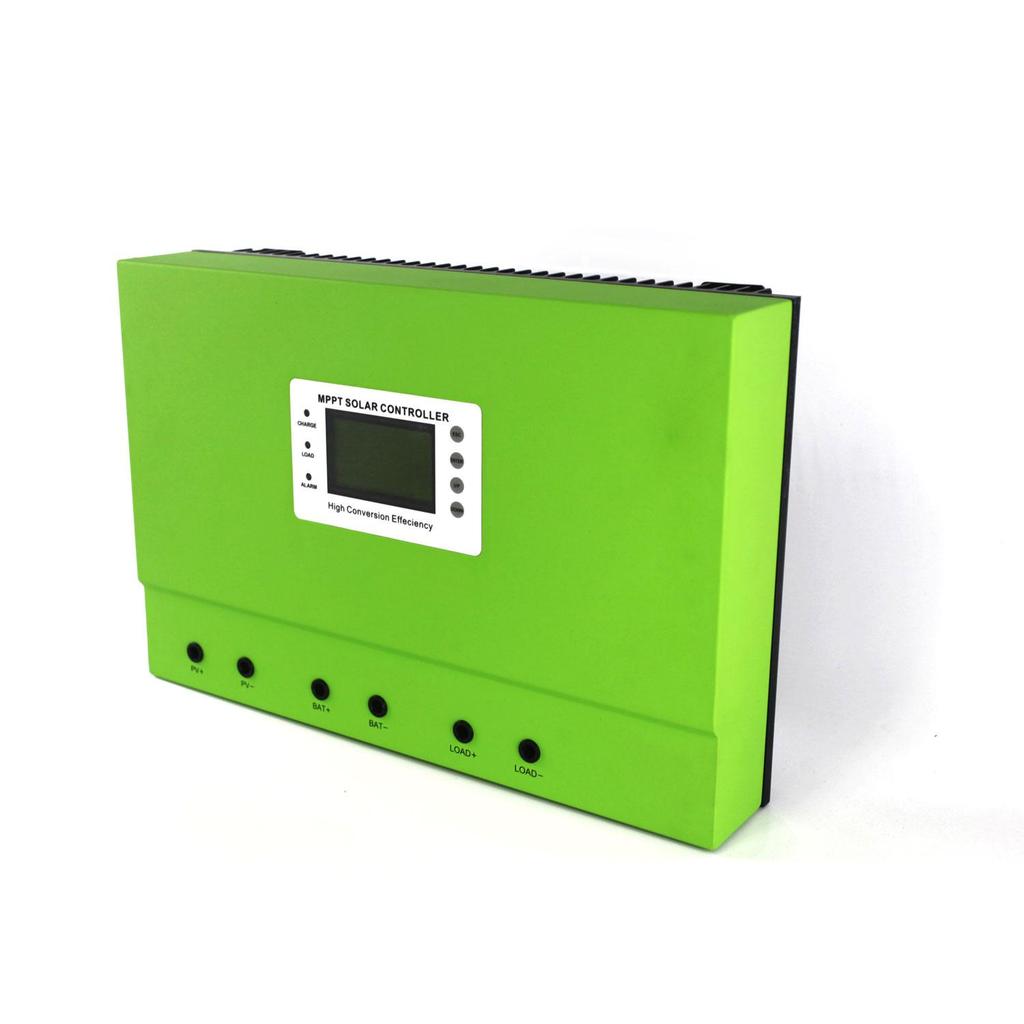
1 User Manual Master-80A/100A series
2 Contents 1 Notes Safety Instructions Unpacking MPPT controller Assembly MPPT controller Connection Introduction of LED/LCD function key MPPT controller Parameter Setting MPPT and PC Connection Technical Parameter Maintenance and Cleaning Storage and waste disposal Recovery Processing and Warranty...21 Model Battery system Max. PV input voltage Rated current Master1 12V/24V/36V/48V DC150V 80A/100A Master2 12V/24V/36V/48V DC300V 80A/100A Master3 96V DC300V 50A/60A

3 1. Notes This manual describes how to install and service Master series MPPT solar charge controller. 1.1 Validity This manual applies to the Master series MPPT solar charge controller which produce by our company: 1.2 Target Group This manual is intended for the installer and the operator. 1.3 All manuals for the device and installed components must be stored in the immediate vicinity of the charge controller and must be accessible at all times. 1.4 Symbols Used The following types of safety messages and general information appear in this document: Warning! WARNING indicates a hazardous situation which, if not avoided, could result in machine stoppage or serious injury. Danger! WARNING indicates a hazardous situation which, if not avoided, could result in machine stoppage or serious injury. Note! In order to operate this device well, please read the operation instruction carefully.

4 2. Safety Instructions 2.1 General Safety Instructions Warning! Due to high input working voltage, please be cautious, otherwise it is danger to life. All work on the charge controller must only be carried out by an electrically skilled person. The appliance is not to be used by children or persons with reduced physical sensory or mental capabilities, or lack of experience and knowledge, unless they have been given supervision or instruction. Children should be supervised to ensure that they do not play with the appliance. Caution! Be careful for high temperature enclosure parts. Do not touch the enclosure of the charge controller during operation. Please settle it on the cooling ventilation environment. Caution! Radiation is harmful for health. Do not stay closer less than 20 cm around the solar charge controller for a long time. 2.2 Explanation of Symbols Below is the explanation for all the symbols shown on the device and label. Symbol Explanation Risk of electric shock Energy stored in capacitors will remain alive for 5 minutes; don t touch within the period after disconnection Both the sides have circuit lines, disconnect both and don t operate within 5 minutes after disconnection No self-serviceable parts inside the enclosure, don t attempt to remove the cover. Only qualified persons are permitted to operate and maintain the equipment. Only insulated tools are permitted to use to reduce risks of hazard to individuals. Beware of hot surface. The solar charge controller can become hot during operation. Avoid contact during operation. And never put any goods onto the equipment under load. Symbols on the Type Label

5 Symbol Explanation CE FCC CB ROHS mark; The device complies with the requirements of the applicable CE FCC CB ROHS guidelines. Important Safety Instructions When using the product, please do remember the below information to avoid the fire, lightning or other personal injury: Warning! Ensure input DC voltage no more than Max. DC voltage.over voltage may cause permanent damage to solar charge controller or other losses, which will not be included in warranty! This chapter contains important safety and operating instructions. Read and keep this operation guide for future reference. Warning! Authorized service personnel must disconnect both DC and battery bank power from the solar charge controller before attempting any maintenance or cleaning or working on any circuits connected to the solar charge controller. Before using the solar charge controller, please read all instructions and cautionary markings on the solar charge controller, and all corresponding sections of this guide. Please use components and parts recommended or sold by UPSEN New Energy. Otherwise may result in a risk of fire, electric shock, or injury to person. To avoid a risk of fire and electric shock, make sure that existing wiring is in good condition and that wire is not undersized. Do not operate the solar charge controller with damaged or substandard wiring. Do not disassemble the solar charge controller. It contains no user-serviceable parts. See Warranty for instructions on obtaining service. Attempting to repair the solar charge controller by yourself may result in a risk of electric shock or fire and will make your warranty invalid. To reduce the risk of electric shock, authorized service personnel must use insulating tool to operate the device. Keep away from flammable, explosive materials to avoid fire disaster. The installation place should be away from humid or corrosive substance.


6 To reduce the chance of short-circuits, authorized service personnel must use insulated tools when installing or working with this equipment. 3. Unpacking 3.1 Device parts checking: A B C D E F 图 1 MPPT controller Accessories figure Object Quantity Description A 1 unit Charge controller B 2 pc Gallow pulley C 1 pc 232 turn to RJ45 communication cable D 1 pc Temperature sensing wire E 1 pc User manual F 1 pc CD (PC software) If there is any part missing, please contact your dealer. 3.2 Check for Transport Damage Check the charge controller for visible external damage, such as cracks in the enclosure. Contact your dealer if you find any damage. 3.3 Identifying the Charge Controller model You can identify the charge controller by the flank label. Contact your dealer if the label model is different with you purchase.


7 4. Assembly 4.1 Operator:technical personnel; 4.2 Selecting the Mounting Location Danger: Danger to life due to fire or explosion. The charge controller enclosure will be hot during operation. Do not mount the charge controller on flammable construction material. Do not mount the charge controller near highly flammable materials. Do not mount the charge controller in potentially explosive areas. Please hang it on the wall, do not put it on the desktop Do not expose the charge controller to direct sunlight to avoid power loss due to overheating. Caution: Danger of burn injuries due to hot enclosure parts. Mount the charge controller in such a way that it cannot be touched inadvertently during operation Dimensions Net Weight Weight:8kg Ambient Conditions The mounting location and method must be suitable for the weight and dimensions to hung on the wall.
8 Mount on a solid surface. The mounting location must be accessible at all times. The charge controller must be easy to remove from the mounting location at any time. The ambient temperature should be between -20 C and +60 C to guarantee optimal operation. Do not expose the charge controller to direct sunlight to avoid power losses due to overheating Safety Clearance Observe the following safety clearance to wall, other devices or objects to ensure sufficient heat dissipation. Direction Sides Top Bottom Safety clearance 30cm 30cm 30cm 5. MPPT controller Connection 5.1 Safety Danger! Danger to life due to high voltage in the solar charge controller. Disconnect the PV array using a disconnection unit and secure it against accidental reactivation. Disconnect the circuit breaker and ensure that it cannot be reconnected. Ensure that no voltage is present in the system. Warning: Risk of injury due to electric shock If all cables with different voltages are routed in parallel, damaged cable insulations may lead to a short circuit. Route all cables separately. Warning: Over voltage can destroy the system. Use an external over voltage protector in areas with an increased risk of thunderstorm and lightning.
9 5.2 Connections of the PV power system PV String Solar charging system connection diagram Solar charge controller device can be connected in series into 1-strings PV modules. Please select PV modules with excellent function and reliable quality. Open-circuit voltage of module arrays connected in series should be less than Max. DC input Voltage (150V); operating voltage should be conformed to MPPT voltage range. Please use PV cable to connect modules to device. From junction box to device, voltage drop is about 1-2%. So we suggest the solar charge controller install near PV module, in order to save wire and reduce DC loss. Note: Please don t connect the PV panel positive or negative to ground. Warning: PV module voltage is very high which belongs to dangerous voltage range, please comply with electric safety rules when connecting The voltage of battery system and types 1) This controller would automatic recognition the DC voltage system : The details please check the illustrate.
10 System type Battery voltage Display 12V system recognize voltage range DC9V~15V 12V SYS 24V system recognize voltage range DC18V~28V 24V SYS 36V system recognize voltage range DC32V~40V 36V SYS 48V system recognize voltage range DC42V~60V 48V SYS 96V system recognize voltage range DC80V~120V 96V SYS Error system Others(Not in the above range) Unknow SYS So, please confirm whether the display of the controller is right after connecting the battery. If it doesn t show the related battery system, please check the battery voltage. 2) The controller had already been set to charge 4 types battery as following form. If have other need, the charge parameter also could be reset through machine and solar eagle. Battery Type The charging voltage of battery type Bulk Voltage (V) Floating Voltage (V) 12V 24V 36V 48V 96V 12V 24V 36V 48V 96V Vented Sealed Gel NiCd Other user-defined (Set by the microcomputer software) Note: default battery type is gel battery The voltage of DC load system and Max. current : This controller had added DC load output function, the output voltage range based on the type of battery bank system. Like the battery bank voltage is 48V, DC output voltage range is within the 48V battery bank working voltage.
11 1) How to turn DC output turn on/off? Please find the DC output control through MPPT or Solar Eagle software. It have 5 way to control it : ON Mode / OFF Mode / Time Control Mode /PV Volt Ctrl / PV&Time Ctrl : Details please check the Setting ; 2) How to set the low voltage protection of DC output? This controller have low voltage output protection and low voltage recovery function. The specific low voltage and recovery voltage could be set based on customer s need. 3) Max. DC output current The Max. DC output current is 100A, if the output current is more than the rated current,the built-in fuse will be burned out. We will provide 2 fuse as back up ; Specification for cable and micro-breaker Model 50A 60A 80A 100A Cable (Cu) 10mm 10mm 16mm 16mm Micro-Breaker 63 A 63 A 110 A 110 A Micro-breaker should be installed between MPPT controller and connection wire. Kindly check the following picture ( we do not provide built-out breaker ): Micro-breaker mounting position diagram MPPT controller work step Cation : Please follow the steps,or the controller and battery will be easily damaged. Please make sure the MPPT had already been connected in right way.
12 Step 1 : Ensure the voltage of the battery is in the range of MPPT controller system allowed. If for 48V system, please check whether the voltage of the battery is in the range of DC42V~DV60V, IF YES, please open the breaker which connected with battery. Step 2 :Turn on the breaker that connected with PV module, if the PV module voltage is in the charging range, then machine will start to work. Step 3 : If need DC load control, please set the DC output control mode, then turn on the DC output breaker The step of turn off machine Cation : Please follow the steps,or the machine will be easy to broke. Step 1 : Turn off the PV input breaker,make sure PV and controller disconnect. Step 2: Turn off the battery breaker, LCD will stop to display, the machine will be complete off. Warning:When the controller is charging for battery, please do not turn off the breaker with battery before PV input have not turn off. Or the machine will have unrecoverable fault and this will not in the warranty. 6 Meaning of LED/LCD and function key 6.1 Panel Description LCD display diagram

13 Meaning of LED and function key LEDs and Buttons ALARM (Red) CHANGE(Blue) LOAD(Green ) UP DOWN ENTER ESC Instruction Controller in fault state Controller start to charge power DC load turn on Page up and numerical increase Page down and numerical reduction Enter in Exit and save data 6.2 Charge Mode This controller have 3 mode : Constant charging stage ( CC Mode ),Constant voltage charging stage ( CV Mode ), Floating charge Stage ( CF Mode ) : In CC Mode,the blue light will flash for every second. In CV Mode,the blue light will flash for every 3 second. In CF Mode,the light will keep on. ( Note : Charging Mode also could check in work status or solar eagle.) 6.3 LCD Display The information of LCD display in different menu.
14 1) Battery voltage, According to the battery voltage related system voltage 2) PV voltage, 3) PV charge power, 4) PV charge current, 5) Battery capacity (%), 6) charge voltage, or battery voltage, 7) charge mode, 8) Time 9) DC LOAD output current 10) DC LOAD output power MPPT controller LCD display shows 3 kinds of menus as follows: Menu No. Menu Type Menu Description 1 Work Status To check the charging state 2 Setting To set the related parameters 3 Information To check the parameters after setting The information of LCD display in different menu. Work Status Fault CC Charging PV Volt Bat Temp HS Temp Load Current Charge Current Normal work will display No Fault. Off normal work will display related Fault. BatOVP mean battery overcharge protection (1. PVOVP mean PV input over voltage protection (2. ChgOCP mean over Charge current protection (3. LoadOCP mean load output over current protection (4. BatOTP mean battery over temperature protection (5. CHGOTP mean MPPT internal over temperature protection (6. PVUVP mean PV input low voltage protection Charging mode: CC or CV or CF PV input voltage If the temperature sensing wire is connected, then it will show the temperature Temperature of heat sink DC load output current Charging current
15 Setting Information Charge Power Charge Volt IP GT Ethernet Set Port ADR Load Set Time&Date Set Bat Type Sel Setting Load :ON Mode Load :OFF Mode Load :PV Volt Control Load :PV&Time Control Load :Time Control Time Date Vented Gel Nicd Sealed CustomDef Max. Charge Current MPPT CHARGER 12V/24/36V/48V 100A 48V BAT CHG SYS IP GT Port ADR LOAD Mode TOTAL Firmware Bat Charging power Charging voltage IP Address Set Gate Address Set Port Set ADR Set DC load output on Set the low voltage / recovery voltage protection / output voltage DC load output off Set the low voltage / recovery voltage protection / output voltage Could set the PV voltage to control DC load output turn on/off Could set the PV voltage and time to control DC load output turn on/off Could set the time of morning on/off Tie Set Date Set Can not set the buck voltage and floating voltage Can set the buck voltage and floating voltage Set the Max. charge current Controller name Controller model System voltage IP Address after user set Gate address after user set Port Number after user set ADR number after user set DC output control mode after user set Total energy from this machine Firmware Ver. Battery Type display

16 7 MPPT Parameter Setting When controller connect with battery and it is in on state,the controller will show the information of Work Status. 7.1 The content which could be set by MPPT controller Please check the details under Setting Interface 7.2 The steps of setting Press DOWN to enter into the main menu ----> Press down to change the page to setting---->press ENTER to get in ----> to press down to chose the information need to be set.for example : Press DOWN to enter into the main menu ----> Press down to change the page to setting---->press ENTER to get in ---->Press DOWN to change to load set---->press ENTER to get in ---->Press UP or DOWN to Load On Mode---->--->Press ESC to save and exit. 8 MPPT and PC Connection 8.1 Solar Eagle introduction Our company had develop PC operational software, customer check all information of solar system and change some parameters, if have our company accredit, even could change some original parameters. The solar eagle are as following picture : Solar eagle overview
17 overview: Get into main interface as following Com Setting ( Com): Get into set the connection of Solar Eagle and PC. Setting: Get into battery type set and load control set interface

18 Data : MPPT working status Event Log: MPPT working status per day Login : Some parameters set need administrator s pass word. 8.2 Then connection of MPPT and Solar Eagle. Could connect trough RS 232 ( COM ) or ( TCP/IP) Connect through RS232 ( COM ) Step 1: Customer s PC have RS232 connector, check the following picture Step 2 : Installed and connected controller,and make sure controller under on state (after controller connect battery,the controller will automatic start ) Step 3: Connect PC and controller with RS232,make sure they had been connect,pc


19 will notice COM, at this time the PC will default to COM1 : Step 4:Open Solar Eagle ( WIN 7,WIN 8 system, please open as administrator ),then press to chose COM communication and enter, it will automatic connect within 10 seconds : Step 5: After all these steps,the information could be check on Solar Eagle. If need to set special parameters,please ask our company to accredit. 2) Customer do not have PC connector. If customer do not have RS232 connector, then customer need to prepare a USB to RS232 connector like the following picture : Step 1: Please install the solar Eagle on PC software (Details please check Solar Eagle PC installation steps), and then install USB to RS232 driver software and make sure it had been connect with RS232. The other step is same as above Connect through LAN ( TCP/IP ) 1)Connect through RJ45,like the following picture
20 Step 1: Please install Solar Eagle,details please kindly check install steps. Step 2: Installed and connected controller,and make sure controller under on state (after controller connect battery,the controller will automatic start ) Step 3: Connect PC and controller through cable, ensure be connected. Step 4: First way :Based on PC GATE ADDRESS and IP ADDRESS to set the controller s PC GATE ADDRESS and IP ADDRESS. GATE ADDRESS is same, but please note the last number of IP address should keep different.like : PC s PC GATE ADDRESS is ,IP ADDRESS is , then set of controller is GATED ADDRESS is ,IP ADDRESS is : Make sure controller and PC in the same LAN. Second way :Based on MPPT controller GATE ADDRESS and IP ADDRESS to set the controller s PC GATE ADDRESS and IP ADDRESS. GATE ADDRESS is same, but please note the last number of IP address should keep different.like : Controller s GATE ADDRESS is ,IP ADDRESS is , then set of PC s GATE ADDRESS is ,IP ADDRESS is : Make sure controller and PC in the same LAN. Step 5: Open Solar Eagle ( WIN 7,WIN 8 system,please open as administrator ), then press to chose TCP/IP communication and fill IP address and port number to enter ; It will automatic connect in 10 seconds : If could not connect, please make sure controller and PC in the same LAN and restart controller. 1)Connect through router as following picture ;
21 Step 1: Please install Solar Eagle,details please kindly check install steps. Step 2: Installed and connected controller,and make sure controller under on state (after controller connect battery,the controller will automatic start ) Step 3: Connect controller and router through cable. Ensure be connected. Step4: Set controller and PC s GATE ADRESS based on router s GATE ADRESS. Keep GATE ADDRESS is same and keep them in the same LAN. Like : router s GATE ADRESS is ,then controller and PC s GATE ADRESS should be Step 5: IP ADRESS setting Set the controller and PC s IP address,based on GATE ADDRESS to set IP ADDRESS, the last number should be different :Like IP s GATE ADRESS is ,PC s IP ADDRESS should be ,the controller s IP ADDRESS should be ; Step 6: Open Solar Eagle ( WIN7,WIN 8 system,please open as administrator ),then press to chose TCP/IP communication and fill IP address and port number,enter ; It will automatic connect in 10s : If could not connect, please make sure controller and PC in the same LAN and restart controller Usage of Solar Eagle When Solar Eagle have been connect,customer could check and change some parameters; If have some special parameters need to be change, please purchase pass from our company : Step 1;Contact us to have password Step 2:Login Step 3:Change parameters
22 9 Parameters Master1-80A/100A series 80A 100A System Type DC12V/24V/36V/48VSYS Automatic recognition MPPT Working Voltage and Range 12V system 24V system 36V system 48V system DC22V~DC150V DC34V~DC150V DC50V~DC150V DC60V~DC150V Input Low Voltage Point Input Overvoltage Protection Point Input Overvoltage Recovery Point DC12V/24V/36V/48VSYS Battery voltage value +2V DC12V/24V/36V/48VSYS DC150V DC12V/24V/36V/48VSYS DC145V Rated charge current DC12V/24V/36V/48VSYS 80A 100A 12V system 960W 1200W Max. PV Power 24V system 1920W 2400W 36V system 2880W 3600W 48V system 3840W 4800W Master2-80A/100A series 80A 100A System Type DC12V/24V/36V/48VSYS Automatic recognition MPPT Working Voltage and Range 12V system 24V system 36V system 48V system DC22V~DC300V DC34V~DC300V DC50V~DC300V DC65V~DC300V Input Low Voltage Point Input Overvoltage Protection Point Input Overvoltage Recovery Point DC12V/24V/36V/48VSYS Battery voltage value +2V DC12V/24V/36V/48VSYS DC300V DC12V/24V/36V/48VSYS DC295V Rated charge current DC12V/24V/36V/48VSYS 80A 100A
23 12V system 960W 1200W Max. PV Power 24V system 1920W 2400W 36V system 2880W 3600W 48V system 3840W 4800W Master3-50A/60A series 50A 60A System Type 96V SYS 96V SYS MPPT Working Voltage and Range Input Low Voltage Point Input Overvoltage Protection Point Input Overvoltage Recovery Point 96V SYS DC125V~DC300V 96V SYS Battery voltage value +2V 96V SYS DC300V 96V SYS DC295V Rated charge current 96V SYS 50A 60A Max. PV Power 96V SYS 4800W 5760W System characteristic 12V system recognize voltage range DC9V~15V 24V system recognize voltage range DC18V~28V 36V system recognize voltage range DC32V~40V 48V system recognize voltage range DC42V~60V 96V system recognize voltage range DC80V~120V Error system The battery voltage is not in above range when the controller is switched on Charge Mode MPPT(Max.imum Power Point Tracking) Method 3 stages: fast charge(mppt),constant voltage, floating charge Soft Start Time 10S Conversion Efficiency 96.5% ~ 99% PV Modules Utilization Rate 99% Charge characteristic Selectable Battery Types (Default type is GEL battery)) Sealed lead acid, vented Gel, NiCd battery (Other types of the batteries also can be defined)
24 Constant Voltage Floating Charge Voltage Please check the charge voltage according to the battery type form. Temperature Factor ±0.02%/ Temperature Compensation Output Ripples(peak) Charger voltage accuracy Discharge characteristic Setting Control Max. discharge current Discharge protection Double-time control ON / OFF mode PV voltage control PV voltage / time delay control Control ON/OFF mode Discharge voltage protection Communication Features RS232 communication 14.2V-(The highest temperature-25 )* mV ±1.5% Controller or PC software 100A fuse On in morning,off in morning / On in night,off in night ON / OFF PV voltage on, PV voltage off PV voltage on, time delay off Set by user Output off when it under (exceed) setting voltage; Choose COM communication port LAN communication Set IP and Gate address for controller and solar eagle ; Then chose TCP communication Protection Function Input Low Voltage Protection Check the input characteristics Input Overvoltage Protection Check the input characteristics Input the reverse polarity protection yes Output overvoltage protection Check the input characteristics Output the reverse polarity protection yes Temperature Protection 95 Temperature rise protection Above 85,decrease the output power, decrease
25 Other Parameters Components Smell Environment Protection Physical Measurement D*W*H (mm) Packing D*W*H (mm) 3A per degree. World brand raw materials. Compliance with EU standards. All rated temperature of electrolytic capacitors not less than 105 No peculiar smell and toxic substances. Meet the 2002/95/EC, no cadmium hydride and fluoride 420*280*102MM 500*360*195MM N.G(kg) 7.5 G.N(kg) 8.5 Safety CE PSE FCC EMC EMC EN61000 Type of Mechanical Protection IP50 Environment Humidity 0~90%RH ( no condense) Altitude 0~3000m Operating Temperature -20 ~ +40 Storage Temperature -40 ~ +75 Atmospheric Pressure 70~106kPa 10. Maintenance and Cleaning 10.1 Replacing the Thermal Fuses Using incorrect thermal fuses may irreparably damage the solar charge controller. Only use the thermal fuses included in the scope of delivery 1. Open the solar charge controller as described in section "Opening the solar charge controller" 2. Remove the broken thermal fuses from the sockets (A and B). 3. Insert new thermal fuses (included in the scope of delivery). 4. Close the solar charge controller as described in section "Closing the solar charge controller".

26 Location of Thermal Fuses 10.2 Cleaning the Cooling Fin Clean the Fan air vents and internal cooling fin regularly by using the dry or small wet cloth to wipe. Attention: Liquid detergent or corrosive solvent cleaning are forbidden. Liquid is not allowed to down in the device. Make the air vent open. Carefully remove dirt with a suitable soft brush. 11. Storage and waste disposal Store the charge controller in a dry place with ambient temperatures between -40 C and +75 C Disposal Dispose of the solar charge controller at the end of its service life in accordance with the disposal regulations for electronic waste which apply at the installation site at that time.
27 12. Recovery Processing and Warranty 12.1 Recovery Processing When the controller abnormal, please check the following question and contact the customer service representative Controller failure mode: Please check the fault tips in the failure mode, and then proceed to the appropriate troubleshooting; When the controller does not start properly: 1. Check the controller external solar panels with the correct polarity. 2. Check Battery Connection; 3. Check Battery; 4. Check circuit breaker; 5. Check internal fuse; If the problem persists, please contact the customer service; Please offer the following information: Equipment information: Model, Order No., serial-number(stickers on the rear plate); Detailed description of the problem (Type of system, occasionally/frequent problems, indicator light, data display, and so on ) Warranty Within the warranty period, it is free to repair for the non-human fault. Otherwise, should charge the cost of repairs Guarantee Card User name: Address: Telephone Number: Date of Purchase: Date of Installation: Installer Contact Information: Solar Charge Controller Serial Number: Battery Voltage: PV Module Type and Manufacturer: Array Wattage: Country: Pose Code: Vendor: Installer: PV Voltage: Notes:
MPPT Solar Charge Controller
 MPPT Solar Charge Controller Automatic Recognition 40A 50A 60A Series Manual Contents 1 Notes on This Manual...3 2 Safety Instructions... 4 3 Unpacking...6 4 Assembly... 7 5 MPPT Controller Connection...8
Appendix. Introduction. Symbol and Signs
 Product Manual Appendix Introduction 18 Software Control through PC (communication port) Input Overvoltage Protection Input Polarity Reversal Protection Output Overvoltage Protection Output Polarity Reversal
GSM Series MPPT PV Controller. Version 1.0. Manual
 GSM Series MPPT PV Controller Version 1.0 Manual 1 Introduction GSM series PV controller is a high-performance Buck solar power equipment, using MPPT (Maximum Power Point Tracking) algorithm makes full
MPPT Solar Charge Controller
 SOLAR MPPT Solar Charge Controller Sart2 Sart2 40A 50A 60A Introduction This is a solar charge controller 40A ~60A that have autoatic ax. power point tracking function with high efficiency that alost 30%~60%
User Manual. Solar Charge Controller 3KW
 User Manual Solar Charge Controller 3KW 1 CONTENTS 1 ABOUT THIS MANUAL... 3 1.1 Purpose... 3 1.2 Scope... 3 1.3 SAFETY INSTRUCTIONS... 3 2 INTRODUCTION... 4 2.1 Features... 4 2.2 Product Overview... 5
User Manual Solar Charge Controller 3KW
 User Manual Solar Charge Controller 3KW Version: 1.3 CONTENTS 1 ABOUT THIS MANUAL... 1 1.1 Purpose... 1 1.2 Scope... 1 1.3 SAFETY INSTRUCTIONS... 1 2 INTRODUCTION... 2 2.1 Features... 2 2.2 Product Overview...
User Manual of MPPT Solar Charge Controller
 User Manual of MPPT Solar Charge Controller Model # Battery Max. PV input system voltage Rated current SMG-B96-80A 96V 430V 80A SMG-B96-100A 96V 430V 100A SMG-B120-50A 120V 430V 50A SMG-B192-60A 192V 430V
USER MANUAL. IPS home inverters with UPS function. IPS home inverter manual
 USER MANUAL IPS home inverters with UPS function Suitable for UPS: - IPS300-SIN - IPS300-SIN-WM - IPS300-SIN-DC - IPS600-SIN - IPS600-SIN-WM - IPS600-SIN-DC - IPS1000-SIN - IPS1000-SIN-DC - IPS1600-SIN
Design Features: User Manual. 1. PFC function. 2. LCD remote control. 3. Battery temperature sensor function.
 User Manual Design Features: 1. PFC function. except BC-1215HT / BC-2407HT 2. LCD remote control. BC-1215HT / BC-2407HT 3. Battery temperature sensor function. 4. Tri-LED color indicator for different
SCC-MPPT Solar Charge Controller
 Table 3: Charging voltage for 4 types of battery Battery Battery 12V battery system 24V battery system Type Type Code Bulk Floating Bulk Floating Vented 01 14.3 V 13.2 V 28.6 V 26.4 V Sealed 02 14.3 V
20A\30A\40A\50A\60A. Maximum PV(voc) Voltage: DC150V
 Voltage: DC150V") Sigineer Power SE3 MPPT Solar Charger Controller User Manuel 20A\30A\40A\50A\60A Maximum PV(voc) Voltage: DC150V LCD display: As follow is MPPT controller s LCD digital tube display number corresponding
Sigineer Power SE3 MPPT Solar Charger Controller User Manuel 20A\30A\40A\50A\60A Maximum PV(voc) Voltage: DC150V LCD display: As follow is MPPT controller s LCD digital tube display number corresponding
SCC-MPPT Solar Charge Controller
 Table 4: Alarm point for low battery voltage table Model Alarm point SCC-MPPT-300 10.5 V SCC-MPPT-600 21.0 V Table 5: Charging hour table for reference Battery Capacity To 90% capacity @ 25A charging current
Solar Charge Controller
 Table 3: Charging voltage for 4 types of battery Battery Type Battery Type Code SC-600W MPPT Bulk Voltage Floating Voltage Vented 01 28.6 V 26.4 V Sealed 02 28.6 V 26.8 V Gel 03 28.6 V 27.4 V NiCd 04 28.6
SCC-MPPT Solar Charge Controller
 Solar Charge Controller Quick Guide 200W 300W 400W 600W 850W V. 2.2 1. Introduction solar charge controller uses PWM-based DSP controller to keep the batteries regulated and prevent batteries from overcharging
User Manual 1KVA/ 2KVA/ 3KVA INVERTER / CHARGER
 User Manual 1KVA/ 2KVA/ 3KVA INVERTER / CHARGER CONTENTS ABOUT THIS MANUAL... 1 Purpose... 1 Scope... 1 SAFETY INSTRUCTIONS... 1 INTRODUCTION... 2 Features... 2 Basic System Architecture... 2 Product Overview...
Installation and Operating Instructions. MPPT Solar System Controller ISC3040
 Installation and Operating Instructions MPPT Solar System Controller ISC3040 ABOUT THIS MANUAL These operating instructions come with the product and should be kept with it as a reference to all user s
PV Generation System. Solar Charge Controller SPECIFICATION
 PV Generation System Solar Charge Controller SPECIFICATION Home application type Version: V5.0 Thank you very much for selecting our product! This manual offers important information and suggestions with
Rover Series. Rover 20A 40A Maximum Power Point Tracking Solar Charge Controller
 Rover Series Rover 20A 40A Maximum Power Point Tracking Solar Charge Controller 0 2775 E. Philadelphia St., Ontario, CA 91761 1-800-330-8678 Version 1.5 Important Safety Instructions Please save these
Eclipse Solar Suitcase
 Eclipse Solar Suitcase Renogy 100W 200W 2775 E. Philadelphia St., Ontario, CA 91761 1-800-330-8678 Version 1.0 Important Safety Instructions Please save these instructions. This manual contains important
User Manual 1KVA-5KVA INVERTER / CHARGER
 User Manual 1KVA-5KVA INVERTER / CHARGER Version: 1.7 Table Of Contents ABOUT THIS MANUAL... 1 Purpose... 1 Scope... 1 SAFETY INSTRUCTIONS... 1 INTRODUCTION... 2 Features... 2 Basic System Architecture...
LS1024BP/ LS2024BP. Solar Charge Controller USER MANUAL
 EPSOLAR LS1024BP/ LS2024BP Solar Charge Controller USER MANUAL Thank you very much for selecting our product! This manual offers important information and suggestions with respect to installation, use
LS1024BP/ LS2024BP. Solar Charge Controller USER MANUAL
 EPSOLAR LS1024BP/ LS2024BP Solar Charge Controller USER MANUAL Thank you very much for selecting our product! This manual offers important information and suggestions with respect to installation, use
CX-SERIES ADVANCED BATTERY CHARGER
 CX-SERIES ADVANCED BATTERY CHARGER Table of Content 1. IMPORTANT SAFETY INFORMATION... 2 1-1 General Safety Precautions... 2 1-2 Battery Precautions... 2 2. FEATURES... 3 2-1 Battery Charging Curve...
Maximum Power Point Tracking (MPPT) KA1224MPPT20A KA1224MPPT40A. Solar Charge Controller. User Manual 20A
 KA1224MPPT20A KA1224MPPT40A. Solar Charge Controller. User Manual 20A") Maximum Power Point Tracking (MPPT) KA1224MPPT20A - KA1224MPPT40A Solar Charge Controller User Manual Model Battery voltage Max. solar panel voltage Charging current KA1224MPPT20A KA1224MPPT40A 12V/24V
Maximum Power Point Tracking (MPPT) KA1224MPPT20A - KA1224MPPT40A Solar Charge Controller User Manual Model Battery voltage Max. solar panel voltage Charging current KA1224MPPT20A KA1224MPPT40A 12V/24V
12/24 VOLT AUTOMATIC SOLAR CHARGE CONTROLLER
 12/24 VOLT AUTOMATIC SOLAR CHARGE CONTROLLER P/No.s SC320 & SC330 WARNING Please read these instructions completely prior to installation. Lead acid batteries can be dangerous. Ensure no sparks or flames
User Manual. Hybrid PV Inverter. Version: 2.1
 User Manual Hybrid PV Inverter Version: 2.1 Table Of Contents 1. Introduction...1 2. Important Safety Warning...2 3. Unpacking & Overview...4 3-1. Packing List... 4 3-2. Product Overview... 4 4. Installation...5
User manual. Solar Hybrid 1-5KVA. Uninterruptible Power Supply / Charger
 User manual Solar Hybrid 1-5KVA Uninterruptible Power Supply / Charger All rights reserved. The information in this document is subject to change without notice. Thank you for purchasing this series UPS.
User Manual 1.5KVA-3KVA INVERTER / CHARGER. Version: 1.1
 User Manual 1.5KVA-3KVA INVERTER / CHARGER Version: 1.1 Table Of Contents ABOUT THIS MANUAL... 1 Purpose... 1 Scope... 1 SAFETY INSTRUCTIONS... 1 INTRODUCTION... 2 Features... 2 Basic System Architecture...
User Manual 1.5KVA-3KVA INVERTER / CHARGER
 User Manual 1.5KVA-3KVA INVERTER / CHARGER Version: 1.0 Table Of Contents ABOUT THIS MANUAL... 1 Purpose... 1 Scope... 1 SAFETY INSTRUCTIONS... 1 INTRODUCTION... 2 Features... 2 Basic System Architecture...
Duo Battery Charge Controller
 Duo Battery Charge Controller RENOGY 10A 20A Pulse Width Modulation Solar Charge Controller Manual 1 2775 E. Philadelphia St., Ontario CA 91761 1-800-330-8678 Version: 1.2 Important Safety Instructions
Installation and Operating Instructions. Solar System Controller ISC3030
 Installation and Operating Instructions Solar System Controller ISC3030 ABOUT THIS MANUAL These operating instructions come with the product and should be kept with it as a reference to all user s of the
Installation and Operating Instructions. Solar System Controller ISC3020
 Installation and Operating Instructions Solar System Controller ISC3020 ABOUT THIS MANUAL These operating instructions come with the product and should be kept with it as a reference to all user s of
MPPT SOLAR CONTROLLER FOR MODELS: 20A baterai 12V 24V
 Main Features MPPT SOLAR CONTROLLER FOR MODELS: 20A baterai 12V 24V 20A MPPT solar charge controller MPPT technology Built-in DSP controller with high performance Automatic battery voltage detection for
User Manual 4KVA/ 5KVA INVERTER / CHARGER. With MPPT Controller
 User Manual 4KVA/ 5KVA INVERTER / CHARGER With MPPT Controller CONTENTS ABOUT THIS MANUAL... 1 Purpose... 1 Scope... 1 SAFETY INSTRUCTIONS... 1 INTRODUCTION... 2 Features... 2 Basic System Architecture...
User Manual 5KVA/5KW INVERTER / CHARGER. Version: 1.3
 User Manual 5KVA/5KW INVERTER / CHARGER Version: 1.3 Table Of Contents ABOUT THIS MANUAL... 1 Purpose... 1 Scope... 1 SAFETY INSTRUCTIONS... 1 INTRODUCTION... 2 Features... 2 Basic System Architecture...
SK-10. Features. Solar Charge Controller User Manual. Important Safety Information
 SK-10 Solar Charge Controller User Manual 12V/24V 10Amp Dear Users: Thank you for selecting our product. Please read this manual carefully before you use this product. This product is of cutting edge design,
The Traveler Series: Wanderer
 The Traveler Series: Wanderer RENOGY 30A Charge Controller Manual 2775 E. Philadelphia St., Ontario, CA 91761 1-800-330-8678 Version: 2.0 Important Safety Instructions Please save these instructions. This
Solar Hybrid Inverter SP Brilliant Series
 User Manual Solar Hybrid Inverter SP Brilliant Series Version: 1.5 Table Of Contents ABOUT THIS MANUAL... 1 Purpose... 1 Scope... 1 SAFETY INSTRUCTIONS... 1 INTRODUCTION... 2 Features... 2 Basic System
LS0512 Solar Charge Controller
 LandStar LS0512 Solar Charge Controller Nominal system voltage Maximum PV input voltage Nominal charge / discharge current 12VDC 35V 5A Contents 1 Important Safety Information... 1 2 General Information...
The Traveler Series: Wanderer
 The Traveler Series: Wanderer RENOGY 30A PWM Charge Controller Manual 2775 E. Philadelphia St., Ontario, CA 91761 1-800-330-8678 1 Version: 2.3 Important Safety Instructions Please save these instructions.
User Manual SOLARMAX 1KVA/ 2KVA/ 3KVA INVERTER / CHARGER
 User Manual SOLARMAX 1KVA/ 2KVA/ 3KVA INVERTER / CHARGER WWW.POWERHIGHWAY.NET CONTENTS ABOUT THIS MANUAL... 1 Purpose... 1 Scope... 1 SAFETY INSTRUCTIONS...... 1 INTRODUCTION... 2 Features... 2 Basic System
c-go 12V/10A 12V/20A Power supply and battery charger Instruction manual
 c-go 12V/10A 12V/20A Power supply and battery charger GB Instruction manual 1 Index 1. Product description... 2 2. Safety advices... 3 3. Mounting and installation... 4 4. Operation... 5 5. Problem solving...
The Traveler Series: Adventurer
 The Traveler Series: Adventurer RENOGY 30A Flush Mount Charge Controller Manual 2775 E. Philadelphia St., Ontario, CA 91761 1-800-330-8678 Version: 2.2 Important Safety Instructions Please save these instructions.
Solar System Controller
 POWER FAULT 50 Amp MPPT Installation and Operating Instructions Solar System Controller ISC5040 ABOUT THIS MANUAL These operating instructions come with the product and should be kept with it as a reference
LS0512R Solar Light Controller
 LandStar LS0512R Solar Light Controller Nominal system voltage Maximum PV input voltage Nominal charge / discharge current 12VDC 35V 5A Contents 1 Important Safety Information... 1 2 General Information...
User Manual 1KVA-5KVA (PF1) INVERTER / CHARGER. Version: 1.0
 INVERTER / CHARGER. Version: 1.0") User Manual 1KVA-5KVA (PF1) INVERTER / CHARGER Version: 1.0 Table Of Contents ABOUT THIS MANUAL... 1 Purpose... 1 Scope... 1 SAFETY INSTRUCTIONS... 1 INTRODUCTION... 2 Features... 2 Basic System Architecture...
User Manual 1KVA-5KVA (PF1) INVERTER / CHARGER Version: 1.0 Table Of Contents ABOUT THIS MANUAL... 1 Purpose... 1 Scope... 1 SAFETY INSTRUCTIONS... 1 INTRODUCTION... 2 Features... 2 Basic System Architecture...
The Traveler Series TM : Adventurer
 The Traveler Series TM : Adventurer 30A PWM Flush Mount Charge Controller w/ LCD Display 2775 E. Philadelphia St., Ontario, CA 91761 1-800-330-8678 Version: 3.4 Important Safety Instructions Please save
SMT. Installation and Operation Manual. Model:SMT WITH MPPT TECHNOLOGY
 SMT WITH MPPT TECHNOLOGY Installation and Operation Manual Model:SMT SMT Dimensions Specification Summary System Voltage 12 V/24V Rated Battery Current 12V, 5A 8A 10A 15A 20A 25A 24V, 5A 8A 10A 15A Rated
Operating Manual MP-3739
 Operating Manual MP-3739 1 About this manual These operating instructions come with the product and should be kept for the life of the product for proper installation and usage. Read these operating instructions
Operating instructions. sonnenprotect for operators. KD-337 Part no Version X00.
 Operating instructions for operators sonnenprotect 1300 KD-337 Part no. 22010 Version X00 info@sonnenbatterie.de www.sonnenbatterie.de EN IMPORTANT Read this documentation carefully before operation. Retain
SOLAR CHARGE CONTROLLER
 SOLAR CHARGE CONTROLLER SCE 1010 / SCE 1515 / SCE 2020 / SCE 3030 Instruction Manual Please read user manual carefully before use. 1.About this manual These operating instructions are part of the product.
SOLAR INVERTER/CHARGER 1000VA/1500VA/2000VA. Appliances. PC TV Light Electricfan
 SOLAR INVERTER/CHARGER SOLAR INVERTER/CHARGER 1000VA/1500VA/2000VA Appliances 420-00300-02 PC TV Light Electricfan Table Of Contents GENERAL PRECAUTIONS... 1 PERSONNEL PRECAUTIONS... 1 INTRODUCTION...
PVES Series User Manual User Manual Shenzhen Pvinergy Technologies Co., Ltd
 User Manual Shenzhen Pvinergy Technologies Co., Ltd PVES Series Solar Residential System Overview Thank you for choosing PVES series solar residential system from Shenzhen Pvinergy Technologies Co., Ltd.
User Manual. 3kW Hybrid PV Inverter HX-3000
 User Manual 3kW Hybrid PV Inverter HX-3000 Table Of Contents 1. Introduction...1 2. Important Safety Warning...2 3. Unpacking & Overview...4 3-1. Packing List... 4 3-2. Product Overview... 4 4. Installation...5
1KVA/ 2KVA/ 3KVA/ 4KVA/ 5KVA MS, LV MPPT INVERTER / CHARGER. User Manual. Version: 2.3
 1KVA/ 2KVA/ 3KVA/ 4KVA/ 5KVA MS, LV MPPT INVERTER / CHARGER User Manual Version: 2.3 Table Of Contents ABOUT THIS MANUAL... 1 Purpose... 1 Scope... 1 SAFETY INSTRUCTIONS... 1 INTRODUCTION... 2 Features...
SOLAR SMART. 12/24V 20Amp MPPT Solar Charge controller with Ethernet
 SOLAR SMART 12/24V 20Amp MPPT Solar Charge controller with Ethernet Embedded web pages, SNMP support, output port for external Relay board and GSM SMS unit port USER MANUAL PLEASE READ THIS MANUAL CAREFULLY
Pro Booster 802Li. Please read and fully understand the instructions in this manual before operation. Keep this manual safe for future reference.
 Please dispose of packaging for the product in a responsible manner. It is suitable for recycling. Help to protect the environment, take the packaging to the local amenity tip and place into the appropriate
User Manual / Manuel utilisateur
 User Manual / Manuel utilisateur Inverter Charger / Convertisseur Chargeur English version...1 English Version 1 Table of Contents ABOUT THIS MANUAL... 3 Purpose... 3 Scope... 3 SAFETY INSTRUCTIONS...
KIT-STCS60D KIT-STCS100D Solar Suitcase 60W and 100W Owner s Manual
 KIT-STCS60D KIT-STCS100D Solar Suitcase 60W and 100W Owner s Manual RNG Group Inc. (Renogy) 14288 Central Ave., Suite A Chino, CA 91710 1-800-330-8678 Product Description The Renogy Solar Suitcases combine
Instruction of Solar Charge Controller. User s Manual
 Instruction of Solar Charge Controller User s Manual 12V/24V 10A/20A Dear Users: Thank you for selecting our product. Please read this manual carefully before you use this product. 0 The controller is
Instruction of Solar Charge Controller. User s Manual
 Instruction of Solar Charge Controller User s Manual 12V/24V 30A Dear Users: Thank you for selecting our product. Please read this manual carefully before you use this product. The controller is for off-grid
Owner s Manual. Contents GP-PWM-10-SQ
 Owner s Manual Contents 1.0 Installation Overview... 2 2.0 Warnings... 2 3.0 Choosing a Location... 3 4.0 Installation Instructions... 3 5.0 Operating Instructions... 4 6.0 Frequently Asked Questions (FAQs)...
12 VOLT 30 AMP DIGITAL SOLAR CHARGE CONTROLLER
 12 VOLT 30 AMP DIGITAL SOLAR CHARGE CONTROLLER User s Manual Congratulations on your Coleman solar product purchase. This product is designed to the highest technical specifications and standards. It will
c-go 24V/6A 24V/8A 24V/12A
 c-go 24V/6A 24V/8A 24V/12A Battery charger GB Instruction manual 1 Index 1. Product description... 2 2. Safety advices... 3 3. Quick start guide... 4 4. Operation... 4 5. Problem solving... 6 6. Specifications...
MPPT Controller PVTS Series User Manual. User Manual. 800W-4000W Hybrid solar inverter. Version: 1.4
 User Manual 800W-4000W Hybrid solar inverter Version: 1.4 Table Of Contents ABOUT THIS MANUAL... 1 Purpose... 1 Scope... 1 SAFETY INSTRUCTIONS... 1 INTRODUCTION... 2 Features... 2 Basic System Architecture...
Don't let the shadows of yesterday hide the sunshine of tomorrow Nandina Morris
 Don't let the shadows of yesterday hide the sunshine of tomorrow. -------------- Nandina Morris Hybrid MPPT Solar Inverter Main Features Pure sine wave inverter Built-in MPPT solar charge controller Selectable
USER MANUAL MPS 1-5KW SERIES
 USER MANUAL MPS 1-5KW SERIES Low Series Frequency Solar and Wind Power Charging Inverter CONTENTS 1 WWW.NEXTGENNRG.COM 1. Introduction... 3 2. Profile Structure 4 2.1. Working Principle 4 2.2.Product Features..5
User s Manual. Wind/Solar Hybrid Street Light Controller. Please Read This User Manual Carefully Prior to. Installation and Operation of This Product.
 User s Manual Wind/Solar Hybrid Street Light Controller Please Read This Carefully Prior to Installation and Operation of This Product. 2012 Version: 1.0 1. Product Introduction The wind/solar hybrid street
SOLAR INVERTER/CHARGER SOLAR INVERTER/CHARGER MPPT 2KVA- 3KVA. Appliances. Airconditioning Fridge. Washing machine
 SOLAR INVERTER/CHARGER SOLAR INVERTER/CHARGER MPPT 2KVA- 3KVA Appliances 420-00288-01 PC TV Airconditioning Fridge Washing machine Table Of Contents ABOUT THIS MANUAL...1 Purpose... 1 Scope... 1 SAFETY
C3 Operating Instructions
 Version 3.1 Stand 09.2014 Robert Bosch (Australia) Pty. Ltd. 1555 Centre Road Clayton, Victoria 3168 C3 Operating Instructions For further information please contact Bosch at: Australia 1300 30 70 40 www.boschautoparts.com.au
Harness the Power of the Sun
 Harness the Power of the Sun Solar Controller / Battery Charger User s Manual Nominal Voltage: 12Volts Rated Solar Current: 30Amps / 40Amps Nominal Voltage: 12Volts / 24Volts Auto Rated Solar Current:
10A / 15A / 20A Solar Charge Controller. PU1024 / PU1524 / PU2024 series INSTRUCTION MANUAL
 10A / 15A / 20A Solar Charge Controller PU1024 / PU1524 / PU2024 series INSTRUCTION MANUAL Dear Customer, Thank you very much for choosing our product. This manual contains important information about
On Line UPS. LUC 1000E / LUC 2000E / LUC 3000E User Manual
 On Line UPS LUC 1000E / LUC 2000E / LUC 3000E User Manual Save This Manual Please read this manual carefully prior to storage, installation, wiring, operation and maintenance of the UPS. This manual contains
MP V 8A Electronic Smart Charger. Instruction and Information Manual
 MP7428 12V 8A Electronic Smart Charger Instruction and Information Manual In order to ensure correct and safe usage of your battery charger, you should read these instructions carefully. Please retain
Owner s Manual. Contents GP-PWM-30-SQ GP-PWM-30-SQ
 Owner s Manual Contents 1.0 Installation Overview... 2 2.0 Warnings... 2 3.0 Choosing a Location...3 4.0 Installation Instructions... 3 5.0 Operating Instructions...4 6.0 Frequently Asked Questions (FAQs)...6
INSTRUCTION MANUAL EPSOLAR. Tracer-3215RN. Maximum Power Point Tracking Solar Charge Controller
 EPSOLAR Utility model patent NO. 201120064092.1 Tracer-3215RN Maximum Power Point Tracking Solar Charge Controller INSTRUCTION MANUAL Thank you very much for selecting our product! This manual offers important
Multi-Mover Charger for model L25
 Multi-Mover Charger for model L25 Important safety instruction. Keep these instructions. This manual contains important instructions for the safety of the user and the operation of the device. 1. SYMBOLS
User Manual 1KVA-5KVA INVERTER / CHARGER
 User Manual 1KVA-5KVA INVERTER / CHARGER Table Of Contents ABOUT THIS MANUAL... 1 Purpose... 1 Scope... 1 SAFETY INSTRUCTIONS... 1 INTRODUCTION... 2 Features... 2 Basic System Architecture... 2 Product
Solar Hybrid Inverter SP Efecto Series
 User Manual Solar Hybrid Inverter SP Efecto Series Version 1.2 Table Of Contents ABOUT THIS MANUAL... 1 Purpose... 1 Scope... 1 SAFETY INSTRUCTIONS... 1 INTRODUCTION... 2 Features... 2 Basic System Architecture...
USER S MANUAL SOLAR POWER INVERTER KW-6KW
 USER S MANUAL ------SOLAR POWER INVERTER------ 1KW-6KW Appliances--------------------------------------------- Content Content Content... 1 1 Figures of unit... 2 2 Specification... 3 3 Front panel...
INSTRUCTION MANUAL EPSOLAR. Tracer-4215RN. Maximum Power Point Tracking Solar Charge Controller
 EPSOLAR Utility model patent NO. 201120064092.1 Tracer-4215RN Maximum Power Point Tracking Solar Charge Controller INSTRUCTION MANUAL Thank you very much for selecting our product! This manual offers important
User Manual 1KVA-5KVA INVERTER / CHARGER. Version: 2.1
 User Manual 1KVA-5KVA INVERTER / CHARGER Version: 2.1 Table Of Contents ABOUT THIS MANUAL... 1 Purpose... 1 Scope... 1 SAFETY INSTRUCTIONS... 1 INTRODUCTION... 2 Features... 2 Basic System Architecture...
3.1 General Information
 1.0 Important Safety Information 2.0 General Information 2.1 Overview 2.3 Features 4 5 5 5 3.0 Installation 3.1 General Information 3.2 Wiring 4.0 Operation 4.1 MPPT Technology 13 4.2 Battery Charging
Installation and operating instructions. Solar charge controller MPPT 10 A / 20 A Z Z
 Installation and operating instructions Solar charge controller MPPT 10 A / 20 A EN 1 Contents 1. About these instructions... 3 1.1 Applicability... 3 1.2 Users... 3 1.3 Description of symbols... 3 2.
Inverter / Charger Accessory for Steca Solarix PLI Phase / Parallel Kit. Installation and operating instructions Z01 17.
 Inverter / Charger Accessory for Steca Solarix PLI 5000-48 3-Phase / Parallel Kit Installation and operating instructions GB Z01 17.31 Table of Contents About this Manual... 2 Purpose... 2 Scope... 2 Keywords
MPPT Maximum Power Point Tracking Series
 www.solariscontroller.com MPPT Maximum Power Point Tracking Series Solar charge controller MPPT 45A/60A User Manual Specification: Model SL4845 SL4860 Battery voltage 12V/24V/36V/48V 12V/24V/36V/48V Charging
Manual. BlueSolar Grid Inverter 1500 / / / / / 230
 Manual EN BlueSolar Grid Inverter 1500 / 230 2000 / 230 2800 / 230 4000 / 230 5000 / 230 Before you start This manual contains important information regarding installation and safe operation of this unit.
User Manual 1.5KVA 3KVA 1.0PF INVERTER / CHARGER
 User Manual 1.5KVA 3KVA 1.0PF INVERTER / CHARGER Table Of Contents ABOUT THIS MANUAL... 1 Purpose... 1 Scope... 1 SAFETY INSTRUCTIONS... 1 INTRODUCTION... 2 Features... 2 Basic System Architecture... 2
Your new LM controller is a state-of-the art device which was developed in accordance with the latest
 CAP LM-series Solar charge controller User Manual Thank you very much for buying this CAP product. Please read the instructions carefully and thoroughly before using the products. Your new LM controller
USER MANUAL. Blazer Vista 1000/1400/2000. Uninterruptible Power System
 USER MANUAL Blazer Vista 1000/1400/2000 Uninterruptible Power System IMPORTANT SAFETY INSTRUCTIONS SAVE THESE INSTRUCTIONS This manual contains important instructions for model Blazer Vista 1000/1400/2000
SMPPT. Solar Charge Controller with Maximum Power Point Tracking. Installation & Operation Manual
 SMPPT Solar Charge Controller with Maximum Power Point Tracking 10A/20A/30A 12V/24V Installation & Operation Manual 1 Dear Consumer: Thank you very much for using our product! We will offer you the permanent
Instruction of Solar Charge Controller. User s Manual
 Instruction of Solar Charge Controller User s Manual 12V/24V 30A Dear Users: Thank you for selecting our product. Please read this manual carefully before you use this product. 0 The controller is for
Lumitester PD-20 Control Kit
 日本語による取扱説明は 17 ページからとなります Lumitester PD-20 Control Kit Operation manual Thank you for purchasing the Lumitester PD-20 Control Kit. To use this kit safely and correctly, read this operation manual carefully
MANUAL (EN 7.12) (IEC 7.12 Ed.5)
 (IEC 7.12 Ed.5)") MANUAL CONGRATULATIONS on the purchase of your new professional switch mode battery charger. This charger is included in a series of professional chargers from CTEK SWEDEN AB and represents the latest
MANUAL CONGRATULATIONS on the purchase of your new professional switch mode battery charger. This charger is included in a series of professional chargers from CTEK SWEDEN AB and represents the latest
APPENDIX: APPROCIMATR BACK-UP TIME TABLE
 9KW-12KW 1 Power Inverter Limitada, dirección Pasaje Enrique Campino 763, La Florida, Santiago CHILE, Tel. 227615261 www.powerinverter.cl email: ventas@powerinverter.cl ABOUT THIS MANUAL 1 SAFETY INSTRUCTIONS
PV Charge Controller SBC-7108 / 7112 / 7120
 PV Charge Controller SBC-7108 / 7112 / 7120 User's Manual NOTE: Please note that features like LCD read out of AH logging of 3 days (see Section 3.3) and 10 Night-light mode (see Section 4.3) are available
80W &100W Folding Solar Panel Kit
 80W &100W Folding Solar Panel Kit CONTENTS Introduction Safety Instructions Installation Operating Features FAQs Troubleshooting Cleaning INTRODUCTION Thank you for purchasing the Navitron 80W/100W Folding
User s Manual. Automatic Switch-Mode Battery Charger
 User s Manual Automatic Switch-Mode Battery Charger IMPORTANT Read, understand, and follow these safety rules and operating instructions before using this battery charger. Only authorized and trained service
DC Master 24/ A
 USERS MANUAL DC Master 24/12 50-60A DC-DC converter MASTERVOLT Snijdersbergweg 93, 1105 AN Amsterdam The Netherlands Tel.: +31-20-3422100 Fax.: +31-20-6971006 www.mastervolt.com ENGLISH Copyright 2015
TRICKLE CHARGER MODEL NO: ATC12VB OPERATION & MAINTENANCE INSTRUCTIONS PART NO: ORIGINAL INSTRUCTIONS LS0618 ISS 2
 TRICKLE CHARGER MODEL NO: ATC12VB PART NO: 6266012 OPERATION & MAINTENANCE INSTRUCTIONS ORIGINAL INSTRUCTIONS LS0618 ISS 2 INTRODUCTION Thank you for selecting this Clarke Trickle Charger. Read this manual