2018 PRODUCT CATALOG YOUR PARTNER IN CRITICAL POWER SOLUTIONS
|
|
|
- Henry Atkinson
- 5 years ago
- Views:
Transcription
1 2018 PRODUCT CATALOG YOUR PARTNER IN CRITICAL POWER SOLUTIONS

")


2 THE EAGLE EYE ADVANTAGE Eagle Eye Power Solutions (EEPS) mission is to lead the industry in Critical Power Solutions, Education, and Customer Support. Being the industry leader requires outstanding products, support services and overall value, so that every customer is 100% satisfied with their EEPS experience. We work with a variety of industries including utility, telecom, data centers, industrial, government & defense, motive power & other applications where backup battery performance is critical. The Leader in Critical Power Solutions
3 Table of Contents BATTERY TRAINING Training Eagle Eye University Training Courses 4-5 STATIONARY BATTERY MONITORING SOLUTIONS BQMS Modular Battery Monitoring up to 960V for 2V, 4V, 6V, 12V Cells/Units 6-7 ipqms Battery Monitoring up to 960V for 1.2V, 2V, 4V, 6V, 8V, 12V Cells/Units 8-9 BDS-Pro Battery Monitoring up to 125V for 1.2V, 2V, 6V, 8V, 12V Cells/Units BMS-icom Battery Monitoring up to 48V for 12V Units 12 BACS-Series Battery Management System VGM-Series Battery String Voltage & Ground Fault Monitoring 15 ELM-Series Battery Electrolyte Level Monitoring BTM-Series Battery Temperature / Thermal Runaway Monitoring 18 SOLUTIONS FOR IEEE & NERC COMPLIANCE Solutions for NERC Compliance Battery Monitoring & Portable Testing Solutions for IEEE Compliance Battery Monitoring & Portable Testing LOAD TESTING SOLUTIONS SLB-Series SMART Constant Current DC Load Banks LB-Series Constant Current DC Load Banks LB-Series AC Load Banks 32 PORTABLE TESTING SOLUTIONS AND DIGITAL INSTRUMENTATION IBEX-Series Battery Voltage & Internal Resistance Testers BT-1000L Lithium-Ion Battery Resistance Tester SG-Ultra Max Digital Hydrometer / Density Meter 37 SG-Ultra Digital Hydrometer / Density Meter 38 SG-1000 Digital Specific Gravity Tester 39 SG-500 Portable Digital Hydrometer 40 DLV-Max Digital Voltmeter & Specific Gravity Test Kit 41 SG-100M In-tank Liquid Density Hydrometer 42 DM-Series Inline Density Meters 43 GFL-1000 Ground Fault Locator 44 DC POWER SYSTEMS DCPS-Shelf-6KW DC Power Shelf DCPS-Shelf-9KW DC Power Shelf 47 SMALL CELL SYSTEMS SC-1000 Small Cell System, VDC, 13A Output SC-1500 Small Cell System, VDC, 30A Output 50 SC-2000 Small Cell System, 48 VDC, 6A Output RECTIFIER MODULES RM-Series 48V, 2KW and 48V, 3KW Rectifier Modules RM-48-KA Control Module 55 INVERTER SYSTEMS SIS-1000 Inverter System MIS-1000 Modular Inverter System MIS-2000 Modular Inverter System MIS-3000 Modular Inverter System MIS-4000 Modular Inverter System MIS-5000 Modular Inverter System ENCLOSURES ENC-1000 Enclosure 73 ENC-2200 Enclosure 74 CUSTOM CABINET SOLUTIONS CAB-Series Custom Cabinets 75 BATTERY CHARGING SOLUTIONS BC-2500 Modular Float Battery Charger & Power Supply, 24, 48, or 130 VDC BC-2200 Modular Float Battery Charger & Power Supply, 12 or 24 VDC BC-1000 Industrial Float Battery Charger, 24, 48, or 130 VDC MC-Series Motive Chargers MP-1000 Modular High Frequency Motive Power Battery Charger 84 LB-1000 Battery Discharger / Charger / Activator 85 GAS DETECTION AND VENTILATION SOLUTIONS HGD-Series Gas Detectors 86 VS-12 Ventilation Systems, 12 x 12 in. 87 VS-24 Ventilation Systems, 24 x 24 in. 88 SPILL CONTAINMENT AND BATTERY ROOM ACCESSORIES SCS-Series Spill Containment Systems BA-Series Battery Room Accessories BA-Series Signs Battery Room Signage 93 BA-Series Tools Insulated Battery Toolkits 94


4 Eagle Eye University Increasing Critical Power Reliability with Hands-on Education 30+ Years of Battery Knowledge EEU s instructors are industry specialists with countless years of instructional and hands-on field experience. Attendees will leave with in-depth real-world knowledge to fulfill their responsibilities. Comprehensive Training Programs In addition to EEU s standard course offering, we have the ability to customize any education program regarding battery reliability - including courses focusing on compliance with common industry standards such as IEEE, NERC, IBC & more. Attendees Across All Industries Industrial engineers, operation managers, power system technicians, facility managers, and emergency & disaster preparedness managers are all positions that will leave with a greater understanding of battery management & reliability - ensuring the safety of their workplaces. Introduction to Battery Management for Standby Power Systems 2-Day Course: December 5-6 This Course will provide an introduction on why and how to implement a battery management program. The program will cover all aspects of battery management from safety, battery types and applications, recommended practices per industry standards and guidelines, testing, and condition analysis. The course is intended for all personnel who have responsibility for the operation and management of batteries in a standby power environment. DC Power Systems 2-Day Course: June 6-7 This course covers the theory and design of the DC power systems that are typically used in standby applications. The attendees will receive instruction on the operating characteristics of the individual system components and their application within specific market areas - including telecommunications and power utilities. The basics of system design from system configuration/sizing through installation and commissioning, will also be covered. This course is intended for any personnel involved in the Specification, Procurement and Installation of DC power systems. 4

5 Comprehensive Battery Training Custom 1 or 2-Day Course: These one or two day non-commercial courses are designed to provide you with an up-to-date insight into current battery technology, standards, sizing, maintenance, failure mechanisms, and monitoring. Associated equipment such as chargers, inverters and UPS s can also be covered. To learn more about our bundled courses and individual course list, pleaes visit Battery Data Analysis 2-Day Course: September This course provides an in-depth look at the measurable battery parameters and their value in proving information with respect to a battery s reliability. Attendees will receive instruction in the use of both limit and trend analysis for both operation and discharge data. This course is intended for supervisory personnel with responsibility for the analysis of the collected battery data plus the determination of any remedial action required. Battery knowledge to the level covered in Battery 101 should be a prerequisite for this course. Battery Day Course: March This course will provide the attendee with a comprehensive overview of the battery types and how they are used in Standby Power applications. The course is a basic introduction to the theory and management of batteries and is intended for personnel who have responsibility for the operation and maintenance of the batteries in Standby Power Systems. Battery Discharge Testing and Analysis 2-Day Course: October 3-4 This course will outline each of the steps required to prepare and carryout a discharge test in accordance with IEEE recommended practices. It will include hands on training during which both a constant power capacity discharge and a service discharge using a typical substation load profile will be carried out. PRC Battery Operation & Maintenance Compliance 2-Day Course: November 7-8 This course is designed to help Utility Companies ensure that their operation and maintenance procedures are in compliance with the battery maintenance requirements of NERC PRC The course will include a review of battery maintenance fundamentals, inspection methods both manual and automated, interpretation of the data collected and the required record keeping. This course is intended for all personnel with responsibility for the implementation and operation of a compliant battery monitoring and testing program. 5


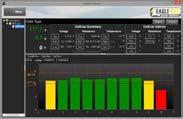
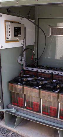
6 BQMS Battery Monitoring System Common Applications: Power Utilities & Distribution, Data Center UPS Product Description The BQMS Battery Monitoring System is designed to measure the aging status of critical backup battery systems by measuring and recording: System voltage, load current, cell voltage, internal/connection resistance, cell temperature and ambient temperature. The BQMS is intended for use on up to 480 vented lead acid (VLA) and valve regulated lead acid (VRLA) battery systems. Installation of the BQMS is non-intrusive and can be completed while the battery system is online. Battery Monitoring Systems BMS-SERIES Communication Control Unit (CCU) Product Features Comprehensive battery management software for 24/7/365 Battery Monitoring. Installation while systems are online. Meets IEEE and NERC standard recommendations for battery monitoring. Utilizes a patented ripple-removing algorithm to filter noise from measurement results Injects minimal, nonintrusive current for battery measurement Simple to install with custom, pre-assembled installation materials. Add-On Products Include: ELM-Series for electrolyte level monitoring, GFM-100 for ground fault monitoring, and the HGD-2000 for hydrogen gas detection. See the EE-NERC-Series page for more information. Standard communication includes Eagle Eye s Centroid 2 Battery Management Software for recording and trending measured parameters. Centroid 2 can be installed on a private network on multiple PC s. Networked systems can utilize SMS/ alerts during alarm conditions. Alternatively, the BQMS can be configured for Modbus output to an existing building management system or SCADA. All BQMS systems have the option to include up to (13) dry contact relays for additional external alarming. BQMS Installation on 125VDC Utility Battery System Battery Management Software Displays and records string voltage, load current, unit voltage, internal/ connection resistance, unit & ambient temperature Trending analysis of measured parameters on a string and cell/unit level with colored, easy to read graphs PDF and Excel reporting Detailed log of alarm outbreak history and SMS alerts Automatically record, save, & playback discharge events Centroid 2 Battery Management Software 6 Tel: Fax: info@eepowersolutions.com

7 BQMS System Composition Typical BMQS systems are configured with the following main components: CCU (Communication Control Unit) A single CCU per system processes all measurement data and handles TCP/IP communication and alarming via dry contacts. Modules Units connected in daisy chain. Wired directly to the battery connections for measurement of cell/unit parameters. BMS/SCADA Modbus TCP/IP TCP/IP Server Client Connection Clamps Physical connection to battery system. Installs to battery inter-cell cables or busbars. Server & Client PC Main computer which interfaces with the CCU and runs Centroid Snet Server application. Client PC s installed on same network for additional users. Measurement Range Accuracy / Resolution Test Speed / Test Load Measuring Interval Data Transfer External Alarming Operating Environment Power Requirements Dimensions Technical Specifications Clamp Connections to Battery Bank Battery Capacity: 5 6,000 Ah System Voltage: VDC Unit Voltage: 2, 4, 6, 12 Volts Load Current: ±10,000 A Temperature: 0 80 C ( F) System Voltage: ±0.5% / 0.1 V Load Current: ±2% / 0.1 A Unit Voltage: ±0.5% / 0.01 V Internal Resistance: ±2% / mω Unit Temperature: ±2% / seconds per bank at less than 2 A per cell Adjustable from every 10 minutes to once per day for unit voltage and internal resistance TCP/IP to proprietary software, Modbus Up to (13) Form C contacts Temperature: 0 65 C ( F) Relative Humidity: Under 80% Input: VDC / VAC CCU: 210 x 76 x 200 mm (8.25 x 3 x 7.9 in) Module: 114 x 70 x 39 mm (4.5 x 2.75 x 1.5 in) SMS/ Applications UPS Systems Power Utilities and Distribution Telecom/Communications Data Centers Oil, Gas & Fuel Mining Battery Suppliers and Manufacturers System Includes BQMS hardware Centroid 2 battery management software All installation materials Prinit manual USB drive with software and support literature Optional Components Electrolyte level, ground fault, & hydrogen gas monitoring Enclosure On-site computer Spare parts kit Battery Monitoring Systems BMS-SERIES 1 BQMS Battery Monitoring Solutions: Up to 480 Cells/Units Tel: Fax: info@eepowersolutions.com


8 ipqms Battery Monitoring System Common Applications: Power Utilities & Distribution, UPS Systems, Telecom/Communications Product Description The ipqms Battery Monitoring System is designed to measure the aging status of critical backup batteries by measuring and recording: system voltage, load current, unit voltage, internal/connection resistance, and temperature. The ipqms is intended for use on up to 448 vented lead acid (VLA), valve regulated lead acid (VRLA), or nickel-cadmium (Ni-Cad) batteries. Installation of the ipqms is non-intrusive and can be completed while the battery system is online. Battery Monitoring Systems BMS-SERIES Main Processing Unit (MPU) Product Features 24/7/365 Battery Monitoring Comprehensive Battery Management Software Installation while systems are online Meets NERC and IEEE standard recommendations for battery monitoring Patented ripple-removing algorithm to filter out noise from measurements Injects minimal current for measurement Simple to install with custom, pre-assembled installation materials Can be powered by AC or DC Standard communication includes Eagle Eye s Centroid 2 Battery Management Software for recording and trending measured parameters. Centroid 2 can be installed on a private network on multiple PC s. Networked systems can utilize SMS/ alerts during alarm conditions. Through the software, the ipqms can utilize Modbus protocol for integration to a distributed control system (DCS) or SCADA (some limitations apply). ipqms Installation on 125VDC Utility Battery System Battery Management Software Displays and records system voltage, load current, unit voltage, internal/connection resistance, temperature. Trending analysis of measured parameters on a string and cell/ unit level with colored, easy to read graphs. PDF and Excel reporting Detailed log of alarm outbreak history and SMS alerts Automatically record, save, & playback discharge & recharge events. Centroid 2 Battery Management Software 8 Tel: Fax: info@eepowersolutions.com V1.4
9 ipqms System Composition Typical ipqms systems are configured with the following main components: MPU (Main Processing Unit) A single MPU per system processes all measurement data and handles communication. Allows on-site viewing of data with LCD. RU (Relaying Unit) Up to 7 RUs per system wire directly to clamps fitted to the battery inter-cell connections. Performs measurement and relays data back to the MPU. TCP/IP Server TCP/IP Client Connection Clamps Physical connection to battery system. Installs to battery inter-cell cables or busbars. Server & Client PC Main computer which interfaces with the MPU. Runs Centroid Snet Server application. Client PC s installed on same network for additional users. Technical Specifications Clamp Connections to Battery Bank Battery Capacity: 5 6,000 Ah Nominal Unit Voltage: 1.2, 2, 4, 6, 8, or 12 Volts Measurement Range: System Voltage: VDC Load Current: ±999.9 A System Voltage: ±0.5% / 0.1 V Load Current: ±1% / 0.1 A Accuracy / Resolution: Unit Voltage: ±0.5% / 0.01 V Internal Resistance: ±2% / mω Unit Temperature: ±2% / 0.1 Test Speed / Test Load: 4 seconds per cell / less than 2 amps AC per cell Adjustable from 10 min to 24 hours (cell/unit readings) Measuring Interval: Data Transfer: TCP/IP to proprietary software, Modbus (1) Internal Storage: Approximately 1-month backup Temperature: 0 65 C ( F) Operating Environment: Relative Humidity: Under 80% Power Requirements: Input: VDC / VAC MPU: 290 x 280 x 90 mm (11.4 x 11 x 3.5 in.) Dimensions: RU: 310 x 178 x 85 mm (12.2 x 5.9 x 3.3 in.) 1) Modbus available from proprietary software only. It is not available directly from the ipqms MPU. Contact Eagle Eye for futher details. SMS/ Applications UPS Systems Power Utilities and Distribution Financial Institutions Telecom/Communications Oil, Gas & Fuel Mining Government/Defense Transportation Operations Battery Suppliers and Manufacturers Medical/Biotechnology Generators System Includes ipqms hardware Centroid 2 battery management software All installation materials USB drive with software and support literature Print manual Optional: Spare parts kit Battery Monitoring Systems BMS-SERIES 1 ipqms Battery Monitoring Solutions: Up to 448 Cells/Units Tel: Fax: info@eepowersolutions.com V1.4 9


 Reduce maintenance costs, improve up-time and manage your battery assets effectively by using the BDS- Pro battery monitoring solution")
10 BDS-Pro Battery Monitoring System Common Applications: Power Utilities & Distribution, UPS Systems, Telecom Product Description The BDS-Pro Battery Monitoring System is designed to measure the aging status of critical backup batteries by measuring and recording: system voltage, load current, unit voltage, internal resistance, and temperature. The BDS-Pro is intended for use on vented lead acid (VLA), valve regulated lead acid (VLRA), and nickel-cadmium (NiCad) battery systems. The included Centroid 2 Battery Management Software records measured data for comprehensive trending analysis. The BDS-Pro Battery Monitoring Solution is an accurate, user-friendly and economic solution for monitoring systems using up to 24 cells/units. Battery Monitoring Systems BMS-SERIES Main Processing Unit (MPU) Reduce maintenance costs, improve up-time and manage your battery assets effectively by using the BDS- Pro battery monitoring solution for your system. Protect yourself from battery failure - one of the leading causes of facility downtime with battery monitoring. Product Features 24/7/365 Battery Monitoring Comprehensive Battery Management Software Installation while systems are online Meets NERC and IEEE standard recommendations for battery monitoring Patented ripple-removing algorithm to filter out noise from measurements Injects minimal current for measurement Simple to install with custom, pre-assembled installation materials. Can be powered by AC or DC Installation to 48V Switchyard Battery Battery Management Software Displays and records string voltage, string current, cell/unit voltage, internal resistance, temperature Trending analysis of measured parameters on a string and cell/ unit level with colored, easy to read graphs PDF and Excel reporting Detailed log of alarm outbreak history and SMS alerts Automatically record, save, & playback discharge & recharge events Centroid 2 Battery Management Software 10 Tel: Fax: info@eepowersolutions.com

11 BDS-Pro System Composition Typical BDS-Pro systems are configured with the following main components: MPU (Main Processing Unit) A single MPU per system processes all measurement data and handles communication. Connection Clamps Physical connection to battery system. Installs to battery intercell cables or busbars. Server PC Main computer which interfaces with the MPU. Runs Centroid Snet Server application. BMS/SCADA Modbus TCP/IP TCP/IP Server Client Client PC Additional computers on the network which communicate with the Server PC. Runs Centroid Viewer application. Measurement Range: Accuracy / Resolution: Test Speed / Test Load: Measuring Interval: Data Transfer: Internal Storage: Operating Environment: Power Requirements: Dimensions: Technical Specifications Clamp Connections to Battery Bank Battery Capacity: 5 6,000 Ah System Voltage: VDC Load Current: ±999.9 A Unit Voltage: 1.2, 2, 4, 6, 8, or 12 Volts (24 units max) System Voltage: ±0.5% / 0.1 V Load Current: ±1% / 0.1 A Unit Voltage: ±0.5% / 0.01 V Internal Resistance: ±2% / mω Unit Temperature: ±2% / 0.5 C 4 seconds per cell / less than 2 amps AC per cell Adjustable from 10 min to once daily (cell/unit readings) TCP/IP to proprietary software, Modbus Approximately 2 weeks backup Temperature: 0 65 C ( F) RH: Under 80% Input: VDC / VAC 195 x 270 x 55 mm (7.7 x 10.6 x 2.2 in.) SMS/ Applications Telecom Power Utilities and Distribution Transportation Operations Oil, Gas & Fuel Generators UPS Systems System Includes BDS-Pro hardware Centroid 2 battery management software All installation materials Fitted CT clamp USB drive with software and support literature Optional: Spare parts kit Battery Monitoring Systems BMS-SERIES 1 BDS-Pro Battery Monitoring Solutions: Up to 24 Cells/Units Tel: Fax: info@eepowersolutions.com

 12V batteries.")
12 BMS-icom Battery Monitoring System Common Applications: Generators, Power Utilities & Distribution Product Description The BMS-icom Battery Monitoring System is designed to measure the aging status of critical backup batteries by measuring and recording: system voltage, load current, unit voltage, internal resistance, and unit temperature. The included Centroid 2 Battery Management Software displays and records measured data for comprehensive trending analysis. The BMS-icom is accurate, repeatable, userfriendly, and cost effective solution for monitoring 48VDC systems using (4) 12V batteries. Battery Monitoring Systems BMS-SERIES BMS-icom Reduce maintenance costs, improve up-time and manage your battery assets effectively by using the BMS-icom battery monitoring solution for your 48V system. Real-time battery monitoring also reduces maintenance and replacement costs by maximizing your battery life. Product Features 24/7/365 Battery Monitoring Installation and maintenance can be done while battery systems are online Meets IEEE and NERC standard recommendations for battery monitoring Utilizes a patented ripple-removing algorithm to filter noise from measurement results Injects minimal current for measurement Simple to install with custom, pre-assembled materials Alerts in real-time during outbreak BMS-icom Installation Measurement Range: Accuracy: Test Speed / Test Load: Measuring Interval: Operating Environment: Power Requirements: Dimensions / Weight: Technical Specifications Battery Capacity: 5 6,000 Ah System Voltage: 0 55 VDC Load Current: ±999.9 A Unit Voltage: 12 V System Voltage: ±0.5% / 0.1 V Load Current: ±1% / 0.1 A Unit Voltage: ±0.5% / 0.01 V Internal Resistance: ±2% / mω Unit Temperature: ±2% / seconds per cell / less than 2 amps AC per unit Adjustable from 10 min to 24 hours (voltage & resistance) Temperature: 0 65 C ( F) Relative Humidity: Under 80% Input: VDC (from connected batteries) 140 x 121 x 44.5 mm (5.5 x 4.8 x 1.8 in) System Includes BMS-icom hardware Centroid 2 battery management software All installation materials Fitted CT clamp USB drive with software and support literature Optional: Spare parts kit 1 BMS-icom Battery Monitoring Solutions: Up to 4 (12V) units 12 Tel: Fax: info@eepowersolutions.com V1.3


, valve regulated lead acid (VRLA), or nickel-cadmium (Ni-Cad) batteries.")
13 BACS Battery Management System Common Applications: Power Utilities & Distribution, UPS Systems, Telecom/Communications Product Description The GENEREX BACS (Battery Analysis and Care System) is an integrated monitoring and management system designed for critical backup batteries. BACS WEBMANAGER and Module Product Features 24/7/365 Battery Management and Monitoring Comprehensive Battery Management Software Easy DCS integration Meets IEEE and IFC standard recommendations for battery monitoring Patented voltage balancing algorithm to eliminate under and over charging Injects minimal current for measurement Simple to install with custom, preassembled installation materials Can be powered by AC or DC BACS unique patented voltage balancing system ensures that all units within a string are maintained at their optimum recommended float voltage eliminating over and undercharging of units within a string to ensure maximum performance and longest life. Thermal runaway protection is included as standard. BACS also measures and records system voltage, unit voltage, unit resistance, unit and ambient temperature and load current (optional). BACS is intended for use on up to 330 vented lead acid (VLA), valve regulated lead acid (VRLA), or nickel-cadmium (Ni-Cad) batteries. Installation of BACS is one of the most straightforward on the market. Standard communication includes GENEREX s BACS VIEWER battery management software for recording and trending measured parameters. BACS is entirely web based and can be installed on a private network on multiple PC s. Networked systems can utilize SMS/ alerts during alarm conditions. BACS can utilize Modbus or SNMP protocols for integration to a distributed control system (DCS) or SCADA (some limitations may apply). Battery Management System BACS-SERIES BACS on a 480 VAC Critical UPS Battery System BACS VIEWER Battery Management Software Battery Management Software Displays and records system voltage, unit voltage, unit resistance, unit temperature and load current (optional). Trending analysis of measured parameters on a string and cell/unit level with colored easy to read graphs PDF and Excel reporting Detailed log of alarm outbreak history and SMS alerts Automatically record, save, & playback discharge & recharge events Tel: Fax: info@eepowersolutions.com
 Manages each unit s float voltage and")

14 WEBMANAGER (Main Unit) A single WEBMANAGER per system processes all measurement data and handles communication. Allows on-site viewing via web browser. BACS System Schematic Typical BACS systems are configured with the following main components: Battery Management System BACS-SERIES BACS Module (1 per unit) Manages each unit s float voltage and reads voltage, resistance and temperature. GX_R_AUX (Relay Unit) 4 Digital inputs and 4 dry contact outputs for thermal runaway notification and control and other auxiliary inputs and outputs. Current Sensor Physical connection to battery system. Installs to battery inter-cell cables or busbars Server & Client PC Main computer which interfaces with the WEBMANAGER. Runs BACS WEBVIEWER. Client PC s installed on same network for additional users. Measurement Range: Accuracy / Resolution: Test Speed / Test Load: Measuring Interval: Data Transfer: Internal Storage: Operating Environment: Power Requirements: Dimensions: Electronic Battery Breaker triggered by GX_R_AUX according to US NORM International Fire Code Technical Specifications BACS C MODULE with Equalizing/Balancing- Temperature, Voltage, and Impedance on every battery/cell BACS BUS CABLE BACS Current Sensor Battery Capacity: 5 6,000 Ah Nominal Unit Voltage: 2, 4, 6, 12 or 16 Volts System Voltage: VDC Load Current: ±999.9A (optional) GX_R_AUX Relaybox System Voltage: ±0.5% / 0.1 V Load Current: ±1% / 0.1 A Unit Voltage: < 0.5% Internal Resistance: 2-4v < 10% 6 16v < 5% Unit Temperature: < 15% 4 seconds per cell / less than 2 amps AC per cell Adjustable from 10 min to 24 hours (cell/unit read- ings) TCP/IP to proprietary software, Modbus, SNMP Approximately 2 years (dependent on system size) Temperature: 0 60 C ( F) Relative Humidity: Under 90% non condensing Input: VDC / VAC Webmanager: 130x125x30 mm (5.1x4.9x1.2 in.) Module: 55x80x24 mm (2.2x3.2x0.9 in.) GX_R_AUX: 75x75x45 mm (3x3x1.8 in.) BACS MEASURING CABLE with two fuses to protect against high impedance DATAS batteries Traps SNMP Modbus-over-IP Profibus/BACNET(opt.) Service Port BACS WEBMANAGER UNMS Remote Monitoring BACS READER BACS PROGRAMMER Applications UPS Systems Power Utilities Distribution Financial Instiutions Telecom/Communications Oil, Gas & Fuel Mining Government/Defense Transportation Operations Battery Suppliers and Manufacturers Meidcal/Biotechnology Generators System Includes BACS hardware BACS VIEWER battery management software Installation materials Software and support literature Printed manual Optional: Spare parts kit BACS VIEWER BACS WEB INTERFACE 1 BACS Battery Management System: Up to 330 Cells/Units 14 Tel: Fax: info@eepowersolutions.com


15 VGM-Series Voltage & Ground Fault Monitors Product Overview The Eagle Eye VGM-Series is an inexpensive and simple solution for monitoring battery string voltage and battery ground faults. For monitoring of both string voltage and ground faults, the VGM-100 is available. The VM-100 is available for only monitoring string voltage, and the GFM-100 is available for monitoring of ground faults. VGM-Series Monitor Product Features Color touchscreen with simple interface Ethernet connectivity to web interface Modbus TCP/IP output for all measured parameters Simple installation with mounting kit for DIN rail or wall mount Monitor 24, 48, 125, or 250 volt batteries Form C contacts for each measured paramter Technical Specifications Measurement Range: 24V: , 48V: 40-56, 125V: , 250V: Accuracy: Better than 1% Fault Resistance Limit Set: kohm Communication: Modbus TCP/IP, (4) Form C contacts Contact Rating: 125 VAC/VDC: 0.5A / 30VDC: 2A Maximum Switching Power: 60 W Power requirements: Powered by connected battery DC voltage Noise Immunity: IEEE/ANSI Standard C 37.90a-1989 compliance Time Delay to Alarm: Adjustable seconds Operating Environment: Temp: 0 55 C ( F), Humidity: 0 95% RH Dimensions / Weight: 147 x 91 x 45 mm (5.77 x 3.56 x 1.77 in.) / 284 g (10 oz.) All models read battery bus status, detect out-of-limit conditions, and provide alarm indications per user settings. The monitor s status, under-voltage and over-voltage trip values, ground fault, time delay, and IP address settings are accessible on the color touchscreen. Output contacts and Modbus protocol are available on all units. The VGM-Series is extremely durable and easily installed as a wall, panel, or DIN rail unit. GFM-100 Installation Kit Includes VGM-Series monitor DIN rail mounting clip Backplate for wall mounting Voltage & Ground Fault Monitors VGM-SERIES 1 VGM-100-XXX (1) Voltage & Ground Fault Monitor, available for 24, 48, 125, or 250 volts 2 VM-100-XXX Voltage Monitor, available for 24, 48, 125, or 250 volts 3 GFM-100-XXX Ground Fault Monitor, available for 24, 48, 125, or 250 volts 1) Determine part number for required voltage, Ex. VGM-100-XXX would be VGM for 125V applications. Tel: Fax: info@eepowersolutions.com V1.3 15


 activate while simultaneously activating the appropriate alarm LED lights.")
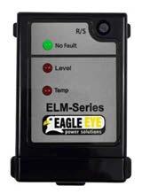
16 ELM-Series Electrolyte Level Monitor Electrolyte Level Monitoring Systems ELM-SERIES ELM Monitor Product Features Low cost monitor for electrolyte level & cell temperature monitoring Auto calibrating sensors adjust to battery in seconds Alarm contacts for external alarming LED lights on monitor and sensors for visual alarming on-site or confirmation of no fault status Fast and easy installation, all cabling cut to length based on simple site survey Applicable to any flooded battery system regardless of voltage & amp-hour Temperature monitoring designed for protection against thermal runaway conditions Product Description The ELM-Series is a reliable electrolyte level and temperature monitoring system designed for flooded batteries. Utilizing low cost, easy to install sensors, the system will alarm on low electrolyte level or higher than normal temperature. In the condition of an alarm, the sensors communicate to the system monitor and dry contact alarm(s) activate while simultaneously activating the appropriate alarm LED lights. In the event that four or more cells trigger an alarm state, the monitor will trigger a group alarm in addition to the single alarm. The alarm contacts may be linked in to any facilities management or alarm system for remote monitoring. Cost-Saving Benefits The ELM allows for significant savings in maintenance costs for battery sites by reducing the man-power needed to inspect battery electrolyte levels. Per NERC Standard PRC-005-6, no periodic on-site inspection of cell electrolyte level is required when remote electrolyte level monitoring with alarming is utilized. ELM Sensor with Mounting Cradle Installation to Battery Cells Sensor Installation Installation of the ELM sensors is simple and fast. Sensors are daisy chained together via provided, pre-cut ribbon cable. All required materials for installation are provided. Each ELM sensor is installed to the front of the battery case via a peel off adhesive Tel: Fax: info@eepowersolutions.com

17 Sensor LED Indicators Each sensor has (3) LED lights. The LED s provide quick visual cues to determine the condition of specific cells in a battery system. No Fault - Green LED illuminated when the sensor is powered on and no fault is detected Level - Red LED illuminates red when the sensor detects the electrolyte level is low Temperature - Red LED illuminates when temperature exceeds set threshold Battery Types: Temperature Alarm Activation: Level Accuracy: Input Voltage: Output Relays Dimensions: (L x W x D) Technical Specifications Sensors Installed to Level Line on Flooded Cells Compatible with all transparent flooded battery types 35 C (95 F), ± 2 C (3.5 F) 49 C (120 F), ± 2 C (3.5 F) 63 C (145 F), ± 2 C (3.5 F) Optional: No temperature alarm ±2 mm (± 0.08 ) above or below line label 12 VDC, AC/DC wall adapter included standard Additional voltage inputs available with optional PSU SPDT volt-free contact relays for: 1+ low electrolyte level detection 4+ low electrolyte level detection 1+ high temperature detection 4+ high temperature detection Monitor: 176 x 80 x 51 mm (6.9 x 1.6 x 3 in.) Sensor: 54 x 35 x 15 mm (2.2 x 1.4 x 0.8 in.) Sensor Cradle: 65 x 52 x 14 mm (2.6 x 2.1 x 0.6 in.) Cables: 1.25mm pitch at length of 305 mm (12 in.) System Includes ELM Monitor ELM Sensors Sensor Mounting Cradles Pre-Cut Ribbon Cables Print Installation Manual 12V AC Wall Adapter Optional: Additional power supplies available for various AC or DC inputs Electrolyte Level Monitoring Systems ELM-SERIES No. Model # (1) Description 1 ELM-4C Electrolyte Level Monitoring Solution: Up to 4 Cells 2 ELM-6C Electrolyte Level Monitoring Solution: Up to 6 Cells 3 ELM-8C Electrolyte Level Monitoring Solution: Up to 8 Cells 4 ELM-12C Electrolyte Level Monitoring Solution: Up to 12 Cells 5 ELM-24C Electrolyte Level Monitoring Solution: Up to 24 Cells 6 ELM-60C Electrolyte Level Monitoring Solution: Up to 60 Cells 7 ELM-120C Electrolyte Level Monitoring Solution: Up to 120 Cells 8 ELM-240C Electrolyte Level Monitoring Solution: Up to 240 Cells 1) Common configurations shown, custom configurations available. Tel: Fax: info@eepowersolutions.com
. Individual sensors are quickly and securely attached to each battery and connected in series from the main unit.")

18 BTM-Series Battery Temperature/Thermal Runaway Monitor Product Overview The BTM-Series is a dependable low-cost scalable solution for protecting your batteries against over-temperature and thermal runaway conditions. Meet IFC and NFPA code compliance (see Product Features). Individual sensors are quickly and securely attached to each battery and connected in series from the main unit. Each thermal sensor is sealed to IP68 (water, gas and dust proof) and the provided special gel-filled connectors are also sealed against acid ingress, dust, and gases. Battery Temperature Monitors BTM-SERIES BTM-Series Monitor & Sensor Product Features Monitor individual unit temperatures for thermal runaway conditions Simple fail-safe change-over relay alarm interfaces Bright LEDs pinpoint individual overtemperature cells No special tools required for installation Sensor circuit break detection Alarm on power supply failure (fail-safe) Code Compliance IFC Thermal Runaway NFPA 1 - Article Thermal Runaway The alarm relays are fail-safe, meaning the user will always get an indication of supply failure. In the event of one or more sensors detecting critical temperature, or a break in the sensor circuit, the monitor warning relay activates and the warning LED on the monitor is illuminated. Simultaneously an LED flashes on the sensor attached to the over-temperature battery, indicating the source of the fault. Should more than 4 cells exceed critical temperature, the system critical alarm relay activates warning of a serious situation at the battery as a whole. Typical Connection of Sensors from Main Monitor Technical Specifications Alarm Range: Activation at 35 C (95 F), ± 3 C (5 F) Reinstatement Temp: 2 C (3.5 F) below activation temperature Input Voltage: DC 12V 2-pin connectors or 12V AC/DC wall adapter Output Relays (2) SPDT volt-free contact relays Output relay contact ratings: 7A at 240 VAC, 10A at 120 VAC Monitor: 84 x 40 x 77 mm (3.3 x 1.6 x 3 in.) Dimensions: Sensor: 38 x 20 x 10 mm (1.5 x 0.8 x 0.4 in.) (L x W x D) Cables: 300 mm (11.8 in.) Compliance: IFC , NFPA 1 - Article Kit Includes BTM Monitor BTM Sensors Installation Cable and Materials 12V AC Wall Adapter Support Literature 1 BTM-Series (1) Battery Temperature Monitor for up to 1) Model number varies per number of cells (e.g. BTM-60C for system with 60 cells) 18 Tel: Fax: info@eepowersolutions.com V1.6


19 BATTERY MONITORING NERC & IEEE Battery Monitoring And Testing Solutions Guide Meet Industry Guidelines & IEEE Requirements NERC 19
.")
20 Battery Monitoring for NERC Compliance The EE-NERC-BMS is Eagle Eye s complete battery monitoring solution for NERC PRC compliance. This standard requires utilities to document and implement programs for the maintenance of all protection systems affecting the reliability of the bulk electric system (BES). Compliance Solutions BATTERY MONITORING for NERC COMPLIANCE Eagle Eye Solution Satisfies Satisfies Satisfies Satisfies Satisfies Satisfies Satisfies Satisfies EE-NERC-BMS Cabinet Solution NERC PRC Table 1-4(f) Exclusions for Protection System Station DC Supply Monitoring Devices and Systems *Maximum Maintenance Interval: No periodic maintenance specified NERC Requirement Attributes Any station dc supply with high and low voltage monitoring and alarming of the battery charger voltage to detect charger overvoltage and charger failure. Any battery based station DC supply with electrolyte level monitoring and alarming in every cell. Any station DC supply with unintentional DC ground monitoring and alarming. Any station DC supply with charger float voltage monitoring and alarming to ensure correct float voltage is being applied on the station DC supply. Any battery based station DC supply with monitoring and alarming of battery string continuity. Any battery based station DC supply with monitoring and alarming of the intercell and/or terminal connection detail resistance of the entire battery. Any Valve Regulated Lead-Acid (VRLA) or Vented Lead-Acid (VLA) station battery with internal ohmic value or float current monitoring and alarming, and evaluating present values relative to baseline internal ohmic values for every cell/unit. Any Valve Regulated Lead-Acid (VRLA) or Vented Lead-Acid (VLA) station battery with monitoring and alarming of each cell/unit internal ohmic value. Under NERC PRC-005-6, battery maintenance falls under Table 1-4(f) Exclusions for Protection System Station DC Supply Monitoring Devices and Systems with no maximum maintenance interval. This table outlines the monitoring and alarming requirements needed to alleviate periodic maintenance activities. Eagle Eye offers solutions to meet each of these requirements as highlighted below: Maintenance Activities No periodic verification of station dc supply voltage is required. No periodic inspection of the electrolyte level for each cell is required. No periodic inspection of unintentional DC grounds is required. No periodic verification of float voltage of battery charger is required. No periodic verification of the battery continuity is required. No periodic verification of the intercell and terminal connection resistance is required. No periodic evaluation relative to baseline of battery cell/unit measurements indicative of battery performance is required to verify the station battery can perform as manufactured. No periodic inspection of the condition of all individual units by measuring battery cell/unit internal ohmic values of a station VRLA or Vented Lead-Acid (VLA) battery is required Tel: Fax: info@eepowersolutions.com

21 Key Benefits Real-time monitoring eliminates required on-site maintenance such as routine manual battery testing Included battery management software allows remote monitoring and alarming Generate reports and view historical measurement data at any time, such as during a NERC audit Available in an industrial enclosure Installation can be performed while the system is online, eliminating the need to de-energize the system Measurement Range: Accuracy / Resolution: Communication: External Alarming: Operating Environment: Power Requirements: Enclosure Specifications: Battery Management Software Measure: string voltage, current, cell/unit voltage, internal/connection resistance, cell/unit & ambient temperature, electrolyte level, ground fault Alarming for all measured parameters Trending analysis of measured parameters on a string and cell/unit level with colored, easy to read graphs PDF and Excel reporting Record, save, & playback discharge events Customize components based on needs, such as electrolyte level and ground fault monitoring Technical Specifications Battery Capacity: 5 6,000 Ah System Voltage: VDC Cell/Unit Voltage: 2, 4, 12 Volts Current: ±10,000 A Temperature: 0 80 C ( F) System Voltage: ±0.5% / 0.1 V Current: ±2% / 0.1 A Cell/Unit Voltage: ±0.5% / 0.01 V Internal/Conn. Resistance: ±2% / mω Unit Temperature: ±2% / 0.01 Electrolyte Level: ±2 mm (± 0.08 ) above or below line TCP/IP to Proprietary Software, TCP/IP Modbus Form C Contact Temperature: 0 55 C ( F) Humidity: 0 80% RH Input: VDC / VAC NEMA 4/12/13, 20 x 20 x 6 in (HxWxD), wall mount, carbon steel, ANSI 61 gray, light-textured polyester powder finish, single-door, 1/4-turn semi-flush oil-tight latch, polycarbonate window Compliance Solutions BATTERY MONITORING for NERC COMPLIANCE 1 EE-NERC-BMS Battery Monitoring Solution for NERC PRC Tel: Fax: info@eepowersolutions.com
22 Portable Testing Solutions for NERC Compliance Compliance Solutions PORTABLE TESTING SOLUTIONS for NERC COMPLIANCE Eagle Eye understands the importance of testing and maintaining batteries per NERC PRC standards. We offer complete battery testing kits and options that meet and exceed these requirements. The purpose of NERC PRC-005 is to document and implement programs for the maintenance of all protection systems affecting the reliability of the Bulk Electric System (BES) so that these protection systems are kept in working order. NERC PRC Table 1-4(a-e) 4 CALENDAR MONTHS - Maximum Maintenance Interval VLA VRLA NiCd Maintenance Activities EEPS Solution X X X Verify station DC supply voltage IBEX-Series X X Inspect electrolyte level SG-Series X X X Inspect for unintentional grounds GFL-Series 6 CALENDAR MONTHS - Maximum Maintenance Interval VLA VRLA NiCd Maintenance Activities EEPS Solution X Inspect condition of all individual units by measuring battery cell/unit internal ohmic values IBEX-Series 18 CALENDAR MONTHS - Maximum Maintenance Interval VLA VRLA NiCd Maintenance Activities EEPS Solution X X X Verify float voltage of battery charger IBEX-Series X X X Verify battery continuity IBEX-Series X X X Verify battery terminal connection resistance IBEX-Series X X X Verify battery intercell or unit-to-unit connection resistance IBEX-Series X Inspect cell condition of all individual battery cells where cells are visible - or measure battery cell/unit internal ohmic values where the cells are not visible IBEX-Series X Inspect physical condition of battery rack IBEX-Series 6 CALENDAR MONTHS or 3 CALENDAR YEARS - Maximum Maintenance Interval VRLA Only Maintenance Activities EEPS Solution X OR Verify that the station battery can perform as manufactured by evaluating cell/ unit measurements indicative of battery performance (e.g. internal ohmic values or float current) against the station battery baseline (6 calendar months) OR IBEX-Series X Verify that the station battery can perform as manufactured by conducting a performance or modified performance capacity test of the entire battery bank (3 calendar years) LB-Series SLB-Series 18 CALENDAR MONTHS or 6 CALENDAR YEARS - Maximum Maintenance Interval VLA Only Maintenance Activities EEPS Solution Verify that the station battery can perform as manufactured by evaluating X OR cell/unit measurements indicative of battery performance (e.g. internal ohmic values or float current) against the station battery baseline (18 calendar months) OR IBEX-Series X Verify that the station battery can perform as manufactured by conducting a performance or modified performance capacity test of the entire battery bank (6 calendar years) 6 CALENDAR YEARS - Maximum Maintenance Interval LB-Series SLB-Series NiCd Only Maintenance Activities EEPS Solution X Verify that the station battery can perform as manufactured by conducting a performance or modified performance capacity test of the entire battery bank (6 calendar years) LB-Series SLB-Series 22 Tel: Fax: info@eepowersolutions.com
23 Ultra-Max Plus Kit The Ultra-Max Plus Kit is the premier kit for NERC compliance for Vented Lead Acid (VLA) and Nickel-Cadmium (NiCad) batteries. The Ultra-Max Plus kit has three parts: an IBEX-Ultra Portable Ohmic Battery Tester, SG-Ultra Max Digital Hydrometer, and Exmons Ultra+ Battery Management Software for all-in-one trending and reporting. The Ultra-Max Plus Kit tests internal resistance (internal ohmic values), voltage, inter-cell resistance (connection resistance), temperature, DC current, ripple current, specific gravity (state of charge), and electrolyte temperature. 1 Ultra-Max-Plus Kit IBEX-Ultra Battery Tester, SG-Ultra Max Digital Hydrometer, Exmons Ultra Plus Software GFL-1000 Ground Fault Locator The GFL-1000 Ground Fault Locator is an essential instrument to pinpoint faulty grounding where electrical cables have breakage and loss to the ground. The unit measures current leakage of DC systems with high resistance. The GFL-1000 is designed to fast-detect, track, and locate virtual grounding faults for both offline and online DC systems. The GFL-1000 is used to meet NERC PRC Compliance by inspecting for unintentional grounds for VLA, VRLA and NiCad batteries every four calendar months. 1 GFL-1000 Ground Fault Locator, Range: V, 10 Hz LB-Series DC Load Banks The LB-Series DC Load Banks monitor system voltage and cell voltage during discharge. The units are portable, durable, economic and come complete with software for data management. Capacity testing is a requirement every six years under NERC PRC for VLA and NiCad battery banks and every three years for VRLA. Discharge testing is a direct measurement of the battery strings capacity and is essential to learning the true health of critical DC systems. The LB-Series has over 80+ models to meet any utility battery system configuration. Compliance Solutions PORTABLE TESTING SOLUTIONS for NERC COMPLIANCE 1 LB-Series* Constant Current DC Load Bank with Monitoring (1-600V, A) *See catalog page for complete model list and comparison Tel: Fax: info@eepowersolutions.com
24 Eagle Eye Power Solutions IEEE Solutions Eagle Eye Power Solutions understands the importance of testing and maintaining batteries per IEEE standards. The most common IEEE standards for battery maintenance, testing & monitoring are below: Maintenance Activities IEEE BATTERY TESTING SOLUTIONS IEEE is the recommended practice for maintenance, testing, and replacement of Vented Lead-Acid (VLA) stationary batteries. IEEE is the recommended practice for maintenance, testing, and replacement of Valve-Regulated Lead Acid (VRLA) batteries for stationary applications. IEEE is the recommended practice for maintenance, testing, and replacement of Vented Nickel-Cad mium Batteries (NiCad) for stationary applications. IEEE is for Selection and Use of Battery Monitoring Equipment in Stationary Applications. VLA VRLA NiCd MONTHLY INSPECTIONS Maintenance Activities (Perform ALL items checked for your battery type) EEPS Solution X X Verify float voltage at the battery terminals IBEX-Series X X X Inspect general appearance and cleanliness of battery room or cabinet, racks, and batteries. Inspect for evidence of terminal, connector, and rack corrosion N/A Visual X X X Verify charger output current and voltage IBEX-Series X X Verify battery electrolyte levels ELM-Series / SG-Series X X X Verify ambient temperature and ventilation systems BMS-Series / IBEX-Series X Inspect for any unintentional battery grounds GFL-Series X Record pilot cell s voltage, specific gravity, and electrolyte level SG-Series X X Inspect all installed battery monitoring systems are operational BMS-Series / ELM-Series QUARTERLY INSPECTIONS VLA VRLA NiCd Maintenance Activities (Perform ALL items checked for your battery type in addition to monthly inspections) EEPS Solution X X X Verify voltage of each cell BMS-Series / IBEX-Series X Verify specific gravity of at minimum 10% of battery string cells SG-Series X X X X X Verify temperature of a representative sample of at minimum 10% of the battery cells Verify float voltage & current at the battery terminals Verify cell internal ohmic resistance values BMS-Series / BTM-Series BMS-Series/ IBEX-Series BMS-Series / IBEX-Series YEARLY INSPECTIONS VLA VRLA NiCd Maintenance Activities (Must perform ALL items checked for your battery type in addition to monthly and quarterly inspections) EEPS Solution X Verify specific gravity of all battery cells SG-Series X Verify AC ripple current IBEX-Series X X Record each cell temperature IBEX-Series X X X Verify cell-to-cell terminal connection resistance BMS-Series/ IBEX-Series X X Inspect cell condition of each cell in contrast to the monthly inspection. Verify the structural integrity of the battery rack N/A Visual 24 Tel: Fax: info@eepowersolutions.com V1.0


25 IEEE / NERC Ultra Max Plus Battery Testing Kit Product Overview The Ultra-Max Plus Kit is the complete solution for testing per IEEE and NERC standards. The Ultra-Max Plus Kit has three parts: an IBEX-Ultra Portable Ohmic Battery Tester, SG- Ultra Max Digital Hydrometer, and Exmons Ultra+ All-in-One Management Software. IBEX-Ultra Key Specs: SG-Ultra Max Key Specs: Complete Ultra Max Plus Kit Technical Specifications Battery Capacity Range: Ah Voltage & I.R. Range: VDC / I.R. 50 VDC Internal Storage: 600 or 4800 Test Results, 4 or 80 Battery Models Resolution: Voltage: 10 mv Resistance: mω Temperature: 0.5 C (0.5 F) Accuracy: DC Voltage: ±0.5% Internal Resistance: ±0.5% Temperature: ±2.0% Measurement Range: Density: g/cm3 Sample Temperature: *0 40 C ( F) Viscosity: 0 1,000 mpa Internal Memory: 1024 Results Resolution: g/cm3 Accuracy: Density: g/cm3 Temperature: ±0.2 C (±0.4 F) Operating Environment: C ( F) The Ultra-Max Plus Kit tests internal resistance, voltage, connection resistance, temperature, DC current, ripple current, specific gravity (state of charge), and electrolyte temperature. Eagle Eye s IEEE/NERC Kits are completely customized to meet your specific battery testing requirements. Let us know your specific applications, testing requirements and budget, and we can tailor a battery testing kit to fit your needs. Features Complete Battery Testing Kit meets IEEE/NERC Requirements for battery maintenance Measures: Internal Resistance, Voltage, Inter-Cell Resistance, Temperature, DC Current, Ripple Current, Specific Gravity and Electrolyte Temperature Store up to 4,800 results with IBEX-Ultra and 1,024 with SG-Ultra Max Exmons Ultra+ Software included for All-in-One battery management IEEE / NERC Requirements Meets IEEE Standards: , , NERC Compliance: PRC Kit Includes IBEX-Ultra Kit SG-Ultra Max Kit Exmons Ultra Plus Management Software Battery Test Equipment IEEE / NERC KITS 1 Ultra Max Plus Kit IBEX-Ultra Battery Tester, SG-Ultra Max Digital Hydrometer, Exmons Ultra Plus Software Tel: Fax: info@eepowersolutions.com


26 SLB-Series DC Load Banks (10-576V, A) SMART DC Load Banks SLB-SERIES SLB-Series DC Load Bank Data Acquisition Case (DAC): Eagle Eye s SLB-Series Load Banks come with an optional DAC package allowing the voltage of EACH CELL to be wirelessly monitored and recorded during discharge. The DAC package allows the user to evaluate the health of each cell and replace only the cells that require replacement - saving time and money by significantly reducing labor hours and replacement costs. Product Overview Eagle Eye s SLB-Series DC load banks are designed for user ease of use, portability, and versatility in mind. Discharge testing batteries is the only verifiable method the capacity of your batteries and the SLB delivers a programmable, constant current load for your testing needs. Whether you are load testing for capacity, performance, acceptance, NERC compliance, or other, the SLB provides an economical complete package solution. Increase employee and battery system safety with PER CELL monitoring and standard built in auto-shutdown features. To suit a variety of industries and diverse applications, Eagle Eye offers over 75 standard models to fit your exact needs at the best price. Product Features Safely monitor live tests remotely with wireless communication to the SLB load bank DataView software includes live monitoring, data recording, and report exporting to Microsoft Excel Discharge auto-shutdown for time duration, total string voltage, capacity, and individual cell voltage Parallel with another SLB-Series unit for increased discharge current capacity Assistant discharge feature allows for compatibility with existing non-slb load banks Increase current and add individual cell monitoring to your existing equipment with SLB-Series Built-in circuit breakers for emergency shutdown and overload protection Optional: Real-time display of voltage for each cell/unit with DAC package for 1.2V, 2V, 6V, 12V cells Optional: Custom DAC packages available for monitoring of uncommon cell voltages and configurations Data Acquisition Case (DAC) DAC Connection to 48V Battery (2V) Cells Typical connection of DAC s to the battery cells include a test lead connected to each cell from the DAC. Each DAC can connect up to 12 cells. DAC s are expandable to any size battery system and are compatible with VRLA, VLA, NiCad, and other battery types Tel: Fax: info@eepowersolutions.com V1.8

27 Discharge DataView Software The included DataView software allows the user to monitor the discharge test in real-time or import and view tested data from the load bank with the provided USB drive. View and print a detailed histogram of each cell s voltage from any point during the discharge test at user defined intervals of 15, 30, or 60 minutes. Cell Voltage: Discharge Current Range: Discharge Voltage Range: Technical Specifications Standard DAC: 1.2V1, 2V, 6V, 12V / Optional 3.6V, 4V, and other custom DAC configurations available upon request Single Load: A / Parallel Load: Up to 1200A Range: V (Max) / Voltage Steps: 12V, 24V, 36V, 48V, 80V, 125V, 240V, 380V, 480V Accuracy: Discharge Current: 1% / Voltage: 0.5% 0.8% Resolution: Sampling Interval: Data Transfer: Display: Operating Environment: Power Requirements: Dimensions: Weight: Real-Time Data Logging of Cell Voltage Discharge Current: 0.1 A or 0.5% / Voltage: V 5 seconds 1 minute USB, Wireless (466 MHz) Backlit LCD 0 40 C ( F) 110/220 VAC 50/60 Hz / DC (from connected batteries) Small: 400 x 177 x 288 mm (15.7 x 7 x 11.3 in) Medium: 520 x 202 x 355 mm (20.5 x 8 x 14 in) Large: 555 x 225 x 435 mm (22.5 x 8.9 x 17.2 in) X-Large: 603 x 400 x 740 mm (23.7 x 15.7 x 29 in) XX-Large: 762 x 406 x 737 mm (30 x 16 x 29 in) Small: 11 kg (24 lbs) Medium: 16 kg (36 lbs) Large: 21 kg (47 lbs) X-Large: 42 kg (93 lbs) XX-Large: 55 kg (122 lbs) (1)The standard DAC package includes quantity of DAC s & cabling for 2V/6V/12V batteries; testing of 1.2V NiCad batteries require additional DAC & cabling. Please make sure to note testing of NiCad to your sales rep. Recorded data exports directly to Microsoft Excel. Users are able to customize the report with company name and location as well as input battery information including battery make, cell type, rated capacity, and more. The complete test criteria, weakest cells, string information, and individual cell information are included in the report. Graphs for string, and cells are also available to view in the software. Kit Includes SLB-Series Load Bank DataView Management Software Carrying Case (for small & medium size models) Set of 3m/10ft Load Cables 3m/10ft Voltage Test Leads PC communication interface Ground Cable AC Power Cord USB Drive with Software/ User Manual (2) Antenna Optional: Standard DAC Package Optional: CT Clamp for Assisted or External Load Testing Optional: Parallel Load Cable SMART DC Load Banks SLB-SERIES 1 SLB-Series* SMART Constant Current DC Load Bank with Monitoring (12-480V, A) *See next page for listing of model numbers *Add DAC after model number for wireless monitoring per cell Tel: Fax: info@eepowersolutions.com V1.8 27
28 SLB-Series Standard Models *Custom models available upon request SMART DC Load Banks SLB-SERIES Maximum Discharge Current At: No Model 12VDC 24VDC 28VDC 36VDC 48VDC 80VDC 125VDC 240VDC 380VDC 480VDC 1 SLB-12/ SLB SLB SLB SLB-24/ SLB-24/ SLB-24/36/ SLB-24/36/48/ SLB-24/ SLB-24/ SLB-24/48-300/ SLB-24/ SLB SLB SLB SLB SLB SLB SLB SLB SLB-48/ SLB-48/ SLB-48/ SLB-48/ SLB v-200A SLB SLB SLB SLB SLB SLB SLB SLB-125/ SLB-125/ SLB SLB SLB SLB SLB Tel: Fax: info@eepowersolutions.com V1.8


29 LB-Series Constant Current DC Load Banks (1 600V, A) Product Overview Eagle Eye s LB-Series Constant Current DC Load Banks are designed for discharge testing, battery capacity testing, acceptance testing, battery maintenance, and other testing of DC systems. The LB-Series Constant Current Load Banks are portable, economic, reliable and user-friendly. With over (100) standard models and an operating range of 5 600V / A. The intelligent technology allows a constant current discharge without the need for any adjustments during the test. The LB-Series is essential in a variety of industries including utilities, telecommunications, UPS, motive power / forklifts, transportation, CATV, and many more. LB-Series CC Load Bank D & S Models In addition to the base CC model, we offer (2) additional model packages that incorporate added features to suit the full range of our customer needs. These advanced models provide the standard CC features Plus Data Management Software, Per Cell Monitoring, LCD Screen, Data Storage, and Programmable Load Steps. See model chart on page 3 for details. Product Features LED display for voltage, current, and test duration Three test conditions for discharge auto-stop: Test Time, End Voltage, Exceeded Capacity, and Cell Voltage* Unit will alarm and end discharge in the event of overheating, abnormal disconnection of battery, and improper polarity detected Cooling fans continue to run automatically after each test to ensure maximum heat protection Previously used parameters saved after powering off the machine Optional: Advanced models which include programmable load steps, cell monitoring, software package, and 5 LCD with touchpad Model Options Features: CC CCD CCS Autosave Test Parameters ü ü ü Adjustable Discharge Current ü ü ü Voltage Auto-Sensing ü ü ü Internal Data Saving ü ü 5 LCD with Touchpad ü ü Data Management Software ü ü Remote Load Control ü ü Programmable Load Steps ü ü Parallel Load ü ü Constant Current DC Load Banks LB-SERIES Cell Monitoring Harnesses PER Cell Monitoring ü Tel: Fax: info@eepowersolutions.com


30 Constant Current DC Load Banks LB-SERIES Real-Time Data of Discharge Event Technical Specifications Discharge Voltage Range: Range: 5 600V (Auto-Sensing) Discharge Current Range: A Per Cell Voltage Type: 1 12V VRLA, VLA, NiCad, and more Accuracy: Discharge Current: 0.1A / Voltage: 0.1V Resolution: Discharge Current: ±0.2A / Voltage: ±0.3%V Data Transfer: RS-232, USB Display: Backlit numeric LED (CC) / 5 backlit LCD (D/S) Data Management Software Eagle Eye s comprehensive software package enables users to monitor discharge events in real time, record data, analyze, remote start & stop tests, and create reports. Reports are exported to Microsoft Excel or Word and can be customized by the user to add company name, location, battery details, and more. Both the raw test data values are available, along with visual graphs for viewing both per cell and string information. Information includes per cell voltages, string voltages, and discharge current from each user-selected data interval. Intervals can be set to as low as every 3 seconds, depending on your test length. Kit Includes LB-Series CC Load Bank 3 m (10 ft) Discharge Cables 110/220 AC Power Cable One-year Standard Warranty USB with Support Literature Optional: Software Package Optional: Cell Monitoring Operating Environment: Power Requirements: 0 40 C ( F) 110/220 VAC 50/60 Hz 1 LB-CC* *See next page for listing of model numbers *Add D or S after model number for ordering advanced models (See model comparison table above for details) 30 Tel: Fax: info@eepowersolutions.com
31 LB-CC Series Discharge Specifications *Custom models available upon request Maximum Discharge Current At: No Model 12VDC 24VDC 28VDC 36VDC 48VDC 72VDC 80VDC 120VDC 240VDC 380VDC 480VDC 1 LB-12/ CC LB-12/ CC LB-24/ CC LB CC LB CC LB CC LB CC LB CC LB CC LB CC LB CC LB CC LB-48/ CC LB-48/ CC LB-48/ CC LB CC LB CC LB CC LB CC LB CC LB CC LB CC Constant Current DC Load Banks LB-SERIES 23 LB CC LB CC LB CC LB CC LB CC LB CC LB CC LB-24/48/120/135/245/ CC LB-24/135/270/ CC LB-24/135/270/ CC LB-48/125/240/ CC LB-48/125/240/ CC Tel: Fax: info@eepowersolutions.com


32 LB-Series Digital AC Load Banks (Up to 480V, kW) Product Overview Model options range from small, portable, low-power units, to high-power indoor or outdoor permanent load solutions. PC software controls offer advanced load profile solutions for working within simple to complex testing applications of various generators, UPS systems, Data centers, power supplies, A/C systems, and other critical AC power sources. Design elements incorporate a robust steel outer chassis with isolated interior chambers for control and cooling elements. This ensures sensitive electronic components are kept away from dirt and debris for long-life reliability in harsh test environments. Portable options include lifting eyes and caster wheels while permanent and outdoor rated units are available with rain covers and louver add-ons. All units come with multiple built-in automatic safety shutdowns and manual override shutdown. AC Load Banks LB-SERIES LB-Series AC Load Bank Features Digital meter for high-precision data read-out User controlled manually or through software with programmed load profile Detailed data management, analysis, and report generation through software Automatic load testing allows user to set custom periods of power and time Display of current, voltage, power, power factor, frequency, and time Emergency manual stop button for quick termination of load test Automatic stop protection for adverse conditions including over-load, over-voltage, high temperature, short-circuit Technical Specifications Load Voltage 208, 240, 380, 400, 415, 440, or 480 volts Load Power 10, 30, 40, 50, 100, 200, 300, 500, 800, or 1000 kw Frequency 50, 60, or 400Hz Power Factor 1 Wiring Options Single Phase / 3-Phase, 3 Wire / 3-Phase, 4-Wire Display LCD multiple function display meter Communication RS232/485, USB Cooling Forced air cooling Environmental C ( F), 95% RH Control Local panel control, PC control Data Management Software Model # LB-10kW LB-30kW LB-40kW LB-50kW LB-100kW LB-200kW LB-300kW LB-500kW LB-800kW LB-1000kW Description LB-10kW Digital AC Load Bank LB-30kW Digital AC Load Bank LB-40kW Digital AC Load Bank LB-50kW Digital AC Load Bank LB-100kW Digital AC Load Bank LB-200kW Digital AC Load Bank LB-300kW Digital AC Load Bank LB-500kW Digital AC Load Bank LB-800kW Digital AC Load Bank LB-1000kW Digital AC Load Bank Order Includes LB-AC Load Bank 10m (30ft.) RS485 software cable RS485/RS232/USB converter Data management software 32 Tel: Fax: info@eepowersolutions.com


33 IBEX-Series Portable Battery Testers Product Description The IBEX-Series Portable Battery Testers are the fastest, smallest and most accurate battery testers in the industry today. Ensure reliability of backup power systems and prevent unexpected failures with the IBEX-Series. Eagle Eye Power Solutions offers multiple IBEX kit options to meet any company s needs and budget. Test internal resistance or conductance, cell voltage, ripple current, temperature, and connection resistance to ensure you are testing per IEEE and NERC Recommendations. IBEX-Ultra Kit Product Advantages IEEE Recommended: Meets IEEE Std and 2005 Recommended Practice for Maintenance, Testing, and Replacement for Stationary Applications Precise & Repeatable: Utilizes a patented ripple-removing algorithm Durable: Simple design with no moving parts Online Tester: Test batteries while they are in service Fast: Automatically measures and stores data in just 3-4 seconds Comprehensive Battery Diagnostic Software: Available software provides an easy to use interface for data management, trending analysis, exporting to excel, viewing graphs and creating reports Battery Bank Management: Upload battery bank and alarm information to the IBEX from the included software Charging ripple current analysis (%) with IBEX-Ultra The IBEX-Series is commonly used in the utility, telecommunications, UPS, transportation, and mission critical industries, and is the preferred battery tester by service groups worldwide. The IBEX injects a minimal test current into the tested batteries and precise & repeatable results appear in just 3 seconds. Battery Management Software is included with each IBEX-Series kit to easily identify bad cells, create reports, save data, and ensure the integrity of backup power systems. IBEX-Ultra with 4-Pin Test Leads and CT Clamp Meter Portable Battery Testers IBEX-SERIES Extender Rods All IBEX Models: (Standard Kit) IBEX-Ultra : IBEX-Pro: IBEX-EX: Optional: IBEX Kits Include IBEX Body, Soft-Poly-Vinyl Bag, 4-Pin Test Leads, Li-Ion Battery, USB Cable, Serial Comm Software, Standard Charger (100 to 240 VAC), Hard Plastic Carrying Case, User Manual Exmons Ultra Software, Temperature Probe, 0.5mΩ Shunt, Spare 4-Pin Test Lead Tips, DC Clamp Meter Exmons Ultra, 0.5mΩ Shunt, Spare 4-Pin Test Lead Tips Standard Kit Modular Extender Rods with LED light (91 cm, 3 ft) for testing UPS cabinets; Thermal Printer, Paper Rolls for IR Printer Tel: Fax: info@eepowersolutions.com V13 33

34 Portable Battery Testers IBEX-SERIES Battery Types: Parameters Measured: Measurement Range: Accuracy: Resolution: Test Speed: Test Load: Alarms: Calibration Method: Data Transfer: Display: Internal Storage: Alarms: Operating Environment: Power Requirements: Dimensions / Weight: Exmons Battery Management Software Technical Specifications VLA, VLRA, Ni-Cad, & Others Internal Ohmic Resistance, Inter-Cell Resistance, Voltage, Temperature, DC Current (Ultra), DC Ripple Current (Ultra) Battery Capacity: Ah Voltage: VDC Ohmic Range: mΩ DC Voltage: ±0.5% Internal Resistance: ±1.0% Temperature: ±2.0% DC Voltage: 10 mv Internal Resistance: mω Temperature: 0.5 C (0.5 F) 3 4 seconds per cell/unit Less than 2 A per cell/unit Voltage Over & Under, Resistance Warning & Fail, Temperature Over Auto Calibration USB Cable to PC Backlit LCD IBEX-Ultra: 4800 Results IBEX-Pro & EX: 600 Results IBEX-Ultra: 80 Alarms IBEX-Pro & EX: 4 Alarms C ( F) Li-ion Battery Pack (2200 mah, 11.1V) 3 4 Hours of testing 175 x 95 x 42 mm (6.8 x 3.7 x 1.6 in) / 0.65 kg (1.4 lbs) Exmons Battery Management Software Import test data from the IBEX and Digital Hydrometers Organize test data into structured groups including the test site, battery bank, and test date Analyze trends in battery health by trending battery systems over time Easily identify problematic cells through colored graphs and cells Generate Reports or export directly to Microsoft Excel Available in three versions to best fit your needs - uploading specific gravity possible with the complete IEEE/NERC Kit Applications Utilities UPS Service Groups Oil, Gas, Fuel Green Energy Nuclear Power Municipalities Mining Hospitals Motive Power Telecommunication Transportation Mission Critical Facilities Industrial Manufacturing Battery Manufacturers and Suppliers Complete IEEE/NERC- Kit IBEX-Ultra Battery Tester SG-Ultra Max Digital Hydrometer Exmons Ultra Plus All-in- One Software 1 IBEX-Ultra ULTRA Intelligent Battery Examiner Kit with Exmons Ultra Software 2 IBEX-Pro PRO Intelligent Battery Examiner Kit with Exmons Ultra Software 3 IBEX-EX Economy Intelligent Battery Examiner Kit with Serial Comm Data Utility 34 Tel: Fax: info@eepowersolutions.com V1.3
 in the ever-expanding production lines of increasingly larger lithium-ion low resistance batteries.")

35 BT-1000L Lithium-Ion Battery Resistance Tester Common Applications: Electronic vehicle, automated machines, production lines Product Description The BT-1000L benchtop battery testers supports simultaneous high-speed measurement (10 seconds per cell) in the ever-expanding production lines of increasingly larger lithium-ion low resistance batteries. BT-1000L Battery Resistance Tester Characteristics of the BT-1000L All-in-One Compact Unit Correct any offset voltage and gain drift that may be present in the circuit to improve the accuracy of voltage measurement. Sample Delay Specify a delay between AC voltage being applied and sampling being started so that measurement can start after the response stabilizes. Prevent Charging or Discharging when AC Voltage is Applied To prevent the battery that is being measured from charging or discharging, the battery impedance meter terminates the applied measurement signal when zero is crossed. Slope Correction Function If measurement signals drift due to the battery characteristics or the input impedance of measurement instrument, the tester applies correction to the linear drift. The battery impedance tester measures the impedance of lithium-ion batteries using the low-frequency AC-IR measurement method without charging and discharging the battery, substantially reducing the time needed to inspect the internal resistance of battery cells. Software is included for viewing measurement data and trending analysis. Product Advantages Low-frequency AC-IR measurement* : Measure the reaction resistance of a battery *The BT-1000L ensures battery cell quality by measuring internal impedance at a low frequency of 1 Hz or below Extremely reliable measurements for low-impedance batteries *The BT-1000L uses a testing current of 1.5 A at the 3mΩ range, which improves the S/N ratio Circuit configuration highly tolerant of contact and wire resistance to provide stable measurements Voltage measurement function equivalent to 6-digit DMM (± % rdg.) Battery Resistance Testers BT-SERIES Temperature Measurement Reaction resistance measured at low frequency is sensitive to temperature. An optional temperature sensor measures the temperature around the battery and associates the results with data, thereby improving the reliability of the measurements. Two Types of Test Probes Clip Type Probe (pictured) for laminated sheet batteries Pin Type Probe for line-embedded applications and various other battery types Tel: Fax: info@eepowersolutions.com V1.0 35


36 Bundled Software PC software included with the BT-1000L Used for measurement and drawing Cole-Cole plots Set desired measurement frequency Send commands to unit to start and stop measurement Export values to text formats like Excel and CSV Battery Resistance Testers BT-SERIES Parameters Measured: Allowable Input Voltage: Impedance Measurement: Voltage Measurement: Temp. Measurement: Basic Accuracy: Functions: Interfaces: Power Supply: Dimensions L x W x H / Weight: Accessories: Display Measured Values Technical Specs Impedance, voltage, temperature Up to 5 V Cole-Cole Plot Drawing Parameters: R, X, Z, θ Frequency: Hz Measurement ranges: mω, mω, mω Testing current: 3 mω range: 1.5 Arms, 10 mω range: 500 marms, 100 mω range: 50 marms Measurement range: V (single range), Measurement time: 0.1 s (Fast) to 1.0 s (Slow) Range: C (14 140ºF), Measurement time: 2.3 s Z: ±0.4% rdg. θ: ±0.1 V: ±0.0035% rdg. ±5 dgt. Temperature: ±0.5 C at C (50 104ºF) Comparator, self-calibration, sample delay, average, contact check, measurement current error, and other RS-232C/USB (virtual COM port) * Cannot be used simultaneously EXT. I/O (NPN/PNP can be switched) 100 to 240 V AC, 50/60 Hz, 80 VA max 330 x 80 x 293 mm (12.99 x 3.15 x in.) 3.7 kg (8.16 lbs.) Power cord 1, Instruction manual 1, Zero-adjustment board 1, USB cable (A-B type) 1, CD-R (communication instruction manual, PC application software, USB driver) 1 1 BT-1000L Battery Impedance Meter (1) 2 Clip Type Probe L2002 Cable length 1.5 m (4.92 ft) 3 Pin Type Probe L2003 Cable length 1.5 m (4.92 ft) 4 Temp. Sensor Z2005 Cable length 1 m (3.28 ft) 5 RS-232C Cable 9637 Cable length 1.8m (5.91 ft) 1) NOTE: Battery test probes not included with tester Tel: Fax: info@eepowersolutions.com V1.0


37 SG-Ultra Max Digital Hydrometer/Density Meter Product Overview The SG-Ultra Max measures the density and density-related values of your sample within seconds. Results appear on the backlit LCD screen and are ready for storage, printout or export to a PC. The lightweight and robust design enable on-site operation in a wide range of environments. Completely sealed, pump spills do not enter the instrument. The SG-Ultra Max digital hydrometer features leak-proof housing for operation in industrial and field applications including battery testing for utilities and telecoms, food & beverage testing, quality control, biotechnology, and many more. Supported measuring units include: density, density at reference temperature, specific gravity, alcohol, API, Baumé, Brix, and five programmable custom functions to ensure your measurement requirements. SG-Ultra Max Measurement Range Accuracy Resolution Repeatability Minimum Sample Volume Communication Display Internal Storage Operating Environment Power Requirements Dimensions Weight Technical Specifications Product Advantages % Accurate, tests density and temperature simultaneously User-Friendly Compact, lightweight, and allows for one-hand measurement Robust & rugged, comes with protective carrying case. Sustains tough field environments with leak-proof housing Wireless Communication Infrared data interface for data exchange with a PC and data export to a printer Stores up to 1,024 total measurement results including time stamp and sample ID Automatic temperature compensation Density: g/cm3 Sample Temperature: C ( F) Viscosity: 0 1,000 mpa Density: g/cm3 Temperature: ±0.2 C (±0.4 F) g/cm g/cm3 2 ml IrDA Interface Backlit LCD 1024 Results C ( F) (2) AA Batteries 140 x 138 x 27 mm (5.5 x 5.4 x 1.0 in) 368 g (13 oz) (1) Sample must not freeze in the measuring cell. SG-Ultra Max Kit Kit Includes SG-Ultra Max 180 mm Sample Tube 2 ml Plastic Syringes Luer Adapter 1/4 UNF IrDA Adapter Interface for Exporting Data to PC Carrying Case Electronic User Manual Digital Hydrometers SG-SERIES 1 SG-Ultra Max Digital Hydrometer, Data-Logging, Range: SG-Ultra Max Ex-Petrol Intrinsically Safe Digital Hydrometer, Data-Logging, Range: Tel: Fax: info@eepowersolutions.com V1.1 37


38 SG-Ultra Digital Hydrometer/Density Meter Product Overview The SG-Ultra digital hydrometer/density meter offers % accurate, temperature-compensated specific gravity, density, and density-related values. Select from multiple units of measure to suit your measurement needs or create custom user-defined requirements. Results include sample identification, measurement unit, temperature correction coefficient, instrument identification and date & time. Results can be downloaded to a printer or PC easily. Reliable results appear in just 3 seconds - just immerse the sampling tube, pull the trigger, and read the final result. Trend results with included management software. The SG-Ultra is commonly used for battery testing (lead-acid & Ni-cad), alcohol and food testing, petroleum testing, and other custom density tests. Digital Hydrometers SG-SERIES SG-Ultra Measurement Range: Accuracy: Resolution: Minimum Sample Volume: Communication: Display: Internal Storage: Operating Environment: Power Requirements: Dimensions: Advantages Accurate % Accurate User-Friendly Compact, lightweight, and allows for one-hand measurement. Large LCD display screen with back-light Robust & rugged, comes with protective carrying case. Sustains tough field environments with a sealed housing Wireless Communication Infrared data interface for data exchange with a PC and data export to a printer (data transfer accessories included) Storage of up to 1100 results including sample ID, measurement unit, temperature correction coefficient, instrument identification, date and time Reliable CE Compliant and One Year Technical Specifications Density: g/cm3 Sample Temperature: C ( F) Viscosity: 0 2,000 mpa Density: g/cm3 Temperature: ±0.2 C (±0.4 F) g/cm3 2 ml IrDA Interface Backlit LCD 1100 Results C ( F) (2) AAA Batteries 229 x 114 x 64 mm (9 x 4.5 x 2.5 in) Weight: 360 g (2.7 oz) Sample Tube Dimensions: 178 x mm / 7 x 1/8 in. Diameter *Custom lengths available (1) Sample must not freeze in the measuring cell SG-Ultra Kit Kit Includes SG-Ultra with Protective Boot Sample Tube (7 x 1/8 ) IrDA Adapters SG-Ultra Management Software Carrying Case User Manual 1 SG-Ultra Digital Hydrometer, Data-Logging, Range: Tel: Fax: info@eepowersolutions.com V1.1


39 SG-1000 Digital Hydrometer / Specific Gravity Tester Product Overview The SG-1000 digital hydrometer / specific gravity tester is specifically designed to quickly & safely measure the temperature-compensated specific gravity of your batteries. The SG-1000 is critical in determining the charge level of leadacid batteries, without touching any liquid or cumbersome cleaning. Singlehanded automatic operation makes this method 10x faster than conventional glass hydrometer and thermometer methods. Measure specific gravity and temperature simultaneously with a press of a button. To measure battery electrolytes, simply extract a sample in your suction tube and press the START button. The temperature-compensated specific gravity is displayed on the screen. The user can select between the specific gravity reading and temperature reading by pressing the SELECT button. Measurement results are displayed in just three seconds. SG-1000 Battery Digital Hydrometer Measurement Range: Accuracy: Advantages % Accurate 10x faster than conventional methods Measure specific gravity and temperature simultaneously Automatic temperature compensation Rugged & Durable Digital display CE Compliant Technical Specifications Specific Gravity of Electrolyte: Available upon request: Sample Temperature: C ( F) ±0.002 Specific Gravity Applications Telecom/Communications Utilities Mining Government/Defense Industrial Manufacturing Motive Power Digital Hydrometers SG-SERIES Resolution: Display: Operating Environment: Power Requirements: Dimensions: Weight: g/cm3 Digital LCD C ( F) 9V Battery 70 x 40 x 210 mm (2.8 x 1.6 x 8.3 in) 235 g (8 oz) SG-1000 Kit Kit Includes SG-1000 Body 9V Battery Three (3) Sample Tubes Hand Strap Carrying Case User Manual 1 SG-1000F Battery Digital Hydrometer, Non-Datalogging, Range: , F 2 SG-1000C Battery Digital Hydrometer, Non-Datalogging, Range: , C Tel: Fax: info@eepowersolutions.com V1.3 39


40 SG-500 Portable Digital Hydrometer Product Overview It is now easier than ever to accurately measure specific gravity in battery fluids with the Eagle Eye Power Solutions SG-500 Portable Digital Hydrometer. The SG-500 is fast, convenient, and easy to use. Simply place a drop or two of battery fluid in the stainlesssteel sample well and press a button. The custom-designed microprocessor delivers a nearly instantaneous readout of specific gravity for the battery fluid to enable quick and easy monitoring of the state-of-charge of your batteries. With specific gravity scales automatically programmed for temperature-compensated readings of battery fluid at 77F or 25C, the SG-500 Hydrometer is ready to measure right out of the box. The large dual-line LCD display is easily read, even in dim light, and removes the subjectivity associated with interpreting where a boundary line crosses tiny scale divisions. Digital Hydrometers SG-SERIES SG-500 Calibration is automatic and does not require the use of special calibration solutions or tools. The SG-500 Hydrometer automatically calibrates itself with water and is ready to use in seconds. No screws to turn and nothing to adjust. Clean-up is just as easy. Simply wipe the sample well with a cloth and you are ready for the next test. No need to constantly squeeze a hand pump to expel your fluid back into the battery cell since the entire test only requires a drop or two of fluid. Furthermore, there are no moving parts to clean, replace or maintain. Upkeep is easy and extremely cost-effective, resulting in a long life and many years of repeated use. Durable and rugged: The SG-500 Hydrometer comes with a sturdy rubber jacket AND a heavy-duty, foam-lined hard case for use in the most challenging of environments. The SG-500 Hydrometer is a technologically-advanced device that puts laboratory-grade precision in the palm of your hand. Backed by the legendary support from our experts in the field of battery testing and technology, it is exactly the kind of cutting-edge instrumentation you would expect from Eagle Eye Power Solutions. SG-500 Kit Kit Includes SG-500 meter Plastic pipettes Rubber Jacket Carrying case Technical Specifications Optic Material: Sapphire Temperature Range: 0 to 50 C (32 to 122 F) Measuring Range: Specific Gravity: Precision: +/ Power Source: 2 AAA Batteries Resolution: +/ Well/Sample Area Material: Stainless Steel Dimensions: 145 x 75 x 37 mm (5.7 x 3 x 1.46 in.) Evaporation/Sample Cover: Yes Weight: 250 grams (8.8 Oz.) Light Source: Precision nm User Calibration Points: 2 Display Type: LCD Body Color: Blue Display Characters: 24 Characters x 2 Lines Body Material: Plastic Display Backlight: Yes Water Resistance: IP64 - Splashing Water Display Language: English, Russian, Spanish, German, French User Messages: Text-Based Temp. Control Method: Auto Temp. Compensation Approval & Certifications: CE 1 SG-500 Portable Digital Hydrometer, Non-Datalogging, Range: Tel: Fax: info@eepowersolutions.com V1.1


41 DLV-Max Battery Testing Kit Product Overview The DLV-Max Battery Testing Kit includes the DLV-Pro data logging voltmeter with the SG-Ultra Max digital hydrometer for a complete solution to voltage and specific gravity testing. The DLV-Pro measures and records cell voltages in less than 1 second, enabling rapid testing of battery cell voltages. Voltages are recorded in two formats: 8 strings of 256 or 20 strings of 48 readings. Specific gravity and temperature readings measured from the SG-Ultra Max are directly uploaded to the DLV-Max in 8 strings of 256 format. Both voltage and specific gravity readings can be combined into a single report. DLV-Pro Voltmeter & SG-Ultra Max Digital Hydrometer Features Record, view, & analyze cell voltage, SG, & temperature readings Record voltage in either 8 strings of 256 or 20 strings of 48 format Record SG in 8 strings of 256 format Perform a full discharge test & analyze results on-site during the test Easily transfer data files to Winmeter 5.1 battery analysis software Export test data to PDF reports or Excel spreadsheets Replay animated discharge tests The DLV-Max kit can also be used to perform a full discharge test on up to 256 cells by recording up to 11 time-stamped voltage readings for each cell, along with time-stamped load current readings and initial and/or final SG readings via the SG-Ultra Max. All test data can be uploaded to a PC using the included Winmeter 5.1 Battery Analysis Software. Generate Reports for Voltage, SG, and Temperature Portable Battery Test Kits DLV-SERIES Technical Specifications Item DLV-Pro SG-Ultra Max Measurement Range Accuracy Memory Cell Voltage: 0 20V 0 4V: ±5mV 4 20V: ±10mV Voltage: 8 by 256, 20 by 48 SG & Temp: 8 by 256 Density: g/cm 3 Temp: 0 80 C ( F) Density: 0.001g/cm 3 Temp: ±0.2 C (±0.4 F) 1024 Sequential Test Results Operating Temp 0 40 C ( F) C ( F) Battery Life 3.7V Li-Ion Rechargeable, 20 Hours Industrial (2) AA, 100 Hours Size / Weight 160 x 76 x 33mm (6.3 x 3 x 1.3in) 298g (10.5oz) 140 x 138 x 27mm (5.5 x 5.4 x 1.0in) 368g (13oz) Kit Includes DLV-Pro Voltage Tester Voltage Test Leads SG-Ultra Max Digital Hydrometer Carrying Case Winmeter Analysis Software 1 DLV-Max Kit DLV-Pro Data Logging Voltmeter, 0 20 VDC SG-Ultra Max Digital Hydrometer, 0 3 g/cm 3 Tel: Fax: info@eepowersolutions.com V1.3 41

42 SG-100M Electronic Hydrometer / Liquid Density Monitor Model # SG-100M Product Overview The SG-100M Specific Gravity Meter/Liquid Density Monitor will replace ordinary glass bulb and optical refractometer hydrometers that are limited in range, utility and functionality. The SG-100M has an in-tank, drop-hang submersible probe that measures, monitors, records, and controls specific gravity/liquid density during a mixing, blending, fermentation, distillation, or plating operation. Digital Hydrometers SG-SERIES SG-100M Digital Hydrometer with Digital Panel Meter and Test Probe Technical Specifications Density: ±0.400 g/cm3 (within the range of Measurement Range (1) lower limit to g/cm3 upper limit) Sample Temperature: C ( F) Pressure Range 0 5 atm (operable in vacuum) Accuracy ±0.005 g/cm3 Resolution ±0.001 g/cm3 Repeatability ±0.004 g/cm3 Data Transfer Analog Voltage Data Logger (optional) 4 20 ma Operating Environment C ( F) Power Requirements Control Module: 120/240 VAC (3) Probe: 0 5 VDC Dimensions Probe Length x Diameter: 280 x 51 mm (11 x 2 in) Weight Probe: 2.3 kg (5 lbs) Cable Length Standard: PVC: m (4 500 ft) Optional: Teflon: m (5 200 ft) (1) Custom density ranges available based on customer specification Designed for customization, the SG-100M has a variety of user-customized options that allow the instrument to fit your exact measuring needs. The measurement probe can be purchased independently for integration into an existing PLC (Programmable Logic Controller). An optional 4-20mA analog output board is also available. Simply submerge the measuring probe up to 500 feet and connect to an electronics module to provide digital readouts of user defined values such as Density, Specific Gravity, Baume, Brix and Alcohol %. Product Features % accurate, measures in liquids or slurries Pressure irrelevant - can monitor density at any depth Remote readout at desired distance from probe Readout can be chosen in preferred engineering units Battery or in-tank operation depending on application Determines concentration mix (by volume or mass) of the sample Large sample temperature ranges up to 106 C (220 F) Kit Includes SG-100M Digital Panel Meter SG-100M CPVC Probe PVC Cable (Standard Lengths: 10 ft to 100 ft) Optional: Teflon Cable for Caustic Solutions 1 SG-100M Digital Panel Meter, CPVC Probe 2 SG-100M Probe Standalone CPVC Probe 3 SG-100M with Output Digital Panel Meter with Analog Output Board (4-20 ma), CPVC Probe 42 Tel: Fax: info@eepowersolutions.com
43 DM-Series Inline Density Meters Model # DM-Series (A) (B) (C) Product Description The DM-Series Inline Density Meters are designed for continuous monitoring and process control of liquid concentration/density and temperature of solutions across a wide range of applications. Available in three different mounting configurations, the DM-Series density meters can be integrated directly into a variety of tanks and inline systems. Temperature compensated values can be measured and displayed in Density, Specific Gravity, Brix, Plato, Baume, API, Concentration, Solid %, and other measurements of density. Designed for process control, measured data outputs through a 4-20 ma signal. Digital communication for remote calibration and monitoring is also available. DM-1000A, DM-1000B, & DM-1000C Applications Industrial Chemical Production: Petroleum, natural gas, oil refining, salt mining Food & Beverage Industry: Beverage, syrup, vegetable oil, & soft drink processing Other Chemical Production: Urea, detergents, ethylene glycol, lubricating oils, acid solutions, & polymers Paper Industry: Black pulp, green pulp, white pulp, alkali solution Measurement Range: Accuracy: Resolution: Communication Output: Display: Technical Specifications Each unit consists of a capacitive-type differential pressure transmitter tied to a pair of pressure repeaters immersed in the solution. Temperature compensation is performed by a temperature sensor located between the two pressure repeaters. Small variations in the process temperature are quickly and accurately calculated through dedicated software. Density: g/cm3 1 Temperature: C 2 / F 2 Density 0 1 g/cm3: g/cm3 Density 0 2 g/cm3: g/cm3 Density 0 3 g/cm3: g/cm3 Temperature: 0.2 C / 0.4 F g/cm ma, HART Protocol Backlit 4.5 Digital LCD Volumetric Displacement: Less than 0.15 cm3 3 / 0.01 in3 3 Power Requirements: Operating Environment: VDC (24 VDC recommended) C / F, 0 90% RH (1) Listed total range, specific models ordered with range of 0-1, 0-2, or 0-3 g/cm3. (2) DM- 1000A & DM-1000B range is C ( F) due to installation method. (3) Varies slightly depending on individual model. Inline Measurement of Density Main Features Monitoring & Process Control: Continuously monitors process, displays real-time measurement and transmits data through a 4-20 ma output Accurate Data Display: Digital LCD displays measured data in user-configurable units which can be alternated during operation Safe for Many Environments: Intrinsically safe with no moving parts, stainless-steel wetted parts, models available for industrial or sanitary environments Easy Operation: User troubleshooting procedures with error messages to help trace cause of problem, user-calibration procedures 1 DM-1000A Vertically Top-Mounted Inline Density Meter, g/cm3, C / F 2 DM-1000B Vertically Side-Mounted Inline Density Meter, g/cm3, C / F 3 DM-1000C Vertically Side-Flex-Mounted Inline Density Meter, g/cm3, C / F Inline Density Meters DM-SERIES Tel: Fax: info@eepowersolutions.com V1.3 43


44 GFL-1000 Ground Fault Locator Product Overview The GFL-1000 Ground Fault Locator is an essential instrument to pinpoint faulty grounding where electrical cables have breakage and loss to the ground. The unit measures current leakage of DC systems with high resistance. The GFL-1000 is designed to fast-detect, track, and locate grounding faults for both offline and online DC systems. Measurement of online DC systems is possible because the output current of the GFL-1000 is very low but the output voltage can be up to 1000V. Ground Fault Locators GFL-SERIES GFL-1000 Kit Output Voltage: Output Frequency: Output Current Limitation: Fault Location Sensitivity: Current Detect Sensitivity: Quick Search Clamp: Current Sensor: Jaw Opening: Display: Operating Environment: Power Requirements: Dimensions: Weight: The GFL-1000 provides accurate solutions for troubleshooting and preventative maintenance, increasing the reliability of electrical equipment. Fast localization and elimination of grounding faults is critical to increase system reliability. The compact and rugged design make it easy to use in small places and harsh environments. The GFL-1000 ground fault locator is widely used in the telecom, utilities, and transportation industries. Advantages Patented technology, pinpoint current leakage fault with grounding resistance lower than 1MΩ Locate faults for both offline and online DC systems Waveform analysis will analyze the interference signal in the circuit Wide output voltage and output frequency ranges allow the GFL-1000 to meet the needs of your electronic equipment Technical Specifications 24, 48, 110, 220, 500, 1000 VDC 10 Hz 5 ma or Unlimited (Max 25mA) 1 MΩ AC/DC Circuit: 0.5 ma 55 mm (diameter), 60 mm (jaw opening) φ8 and φ20 60 mm (2.36 in) Backlit Color LCD Temperature: C ( F) 8.4 VDC Li-ion Battery 360 x 260 x 135 mm (14.2 x 10.2 x 5.3 in) 7 kg (15.4 lbs) 1 GFL-1000 Ground Fault Locator, Range: V, 10 Hz Signal Receiver Kit Includes GFL-1000 Signal Generator Power Adapter Qty. (2) Signal Testing Leads Qty. (2) Alligator Clips Punctuation Clip Signal Receiver Qty. (2) Dual-Range Current Detector Qty. (2) Batteries 120/220 50/60 Hz Battery Charger Carrying Case 44 Tel: Fax: info@eepowersolutions.com V1.1

45 DCPS-Shelf-6KW DC Power Shelf Common Applications: Telecom - Wireless and Outside Plant, Network, Broadband/Cable DCPS-Shelf-6KW Product Description Eagle Eye s DCPS-Shelf-6KW is a simple, cost competitive power shelf for telecom and network applications. With an optional control module and independent IEC AC input plugs dedicated for each module, it is ideal for in-building wireless systems. The DCPS-Shelf-6KW is designed for an active radio frequency (RF) DAS conditioner and management system that optimizes signal performance between a small cell or high-power base station transceiver (BTS) and a DAS. Product Features High efficiency, 96% typical Up to 6 kw of power 1RU height for compact installations Rear-access wiring for AC input, DC output, alarms & communication Independent IEC-320 AC input plugs dedicated for each rectifier module Control module for full alarms and monitoring (optional) External communication via TCP/ IP Web-Based Software TCP/IP SNMP V3 (pending) Operating Temperature Storage Temperature Operating Humidity Storage Humidity Cooling General Specifications C ( ºF) Derating above 55ºC (131ºF) C ( ºF) 10 90% (non-condensing) 5 95% (non-condensing) Fan-cooled rectifiers (front-to-back airflow) Vibration Hz, 2G, Mini Period, 60 min each (3 axes) Shock 20G peak acceleration Reliability >150,000 hours (per MIL STD 217F) Size 483 x 424 x 43.9 mm (19 x 16.7 x 1.73 in.) Weight 11.1 kg (24.5 lbs.) DC Powrer Shelfs DCPS-SERIES Emissions Electrostatic Discharge Radiated Susceptibility EFT/Bursts Surges Conducted Immunity Voltage Dips Voltage Interruptions Fluctuations & Flicker Emissions EN55022 Level B (Conducted) EN , 4 kv Contact / 8 kv Air EN , 26 MHz MHz, 10 V/m, 80% AM EN , 2 kv EN , 2 kv Earth, 1 KV Line-Line EN , 150 KHz - 80 MHz, 10 Vrms, 80% AM EN , 95% Dip, 10 ms / 30% Dip, 500 ms EN , 95% reduction, 5 ms EN Tel: Fax: info@eepowersolutions.com V1.0 45
46 Voltage Frequency Inrush Current Protection Leakage Hold-up Efficiency Harmonics Input Specifications VAC (Full power above 180 AC) (See derating curve for < 176 VAC) Hz <20 A at 220 VAC (Max cold start) per module 10.9 A per module (max, continuous) Input under / over-voltage; under / over-temp <3.5 ma across rated input voltage range >20 ms (220 VAC, 75% load) 96% at 220 VAC (30 70% load, typical) EN Class D compliant (>0.99 PF) DC Powrer Shelfs DCPS-SERIES Output Specifications Output Voltage -54 VDC (adjustable: to -58 V) Output Current 111 A, max (3 Rectifier Modules); see I out chart Line Regulation ±0.5% max, across full input range Load Regulation ±0.5% max, across full load range Ripple 1.0% p-p, max (20 MHz BW) Output Adjustment VDC Setpoint Accuracy ±0.5% Excursion ±5% max (Step Load: 10 90% or 90 10%) Recovery 50 ms, max Over-Current % (Auto-Recovery) Ov Protection % (Recycle input to reset) Control Specifications Current Sharing ±0.5% Module-to-Module (10 90% Load) Output OV Alarm -43 to -44 VDC Output OV Shutdown to VDC Input UV Protection Shutdown: VAC; Restart: VAC Input OV Protection Shutdown: VAC; Restart: VAC Low Temp Protection Shutdown: -40 C ±5 C; 5 C hysteresis restart High Temp Protection Shutdown: +75 C ±5 C; 5 C hysteresis restart UL/cUL CE Mark CB Telcordia Safety Standards (pending) Low voltage directive (pending) IEC , EN (pending) NEBS GR63 CORE Zone 4 (pending) 1 DCPS-Shelf-6KW DC Power Shelf 46 Tel: Fax: info@eepowersolutions.com V1.0

47 DCPS-Shelf-9KW DC Power Shelf Common Applications: Telecom - Wireless and Outside Plant, Network, Broadband/Cable, Utilities DCPS-Shelf-9KW Product Features Hot pluggable Controlled, measured and reported by RS232, TCP/IP, SNMP V3 Modular design for accommodating high power applications 19 inch rack mount type Local Remote Alarm Relays Digital Inputs AC Input Input Voltage Range Single Phase ( VAC) Frequency Hz Configuration Individual Rectifier Feeds Input Current 2K Rectifier 3K Rectifier Inrush 20 Amps 25 Amps Operating TBA TBA Control & Monitoring Keypad/Display, Web Browser TCP/IP, SNMP V3 Web Browser 6 User Defined 4 User Defined Product Description The DCPS - 9K is a 2U 19 rack mountable integrated powersystem which provides up to166 Amps at -54VDC with the RM48-3K or 111Amps with the RM48-2K 96% efficient rectifiers.the Distribution section provides the ability to terminate 2 batterystrings each with its own battery disconnect circuit breaker. 10 Load Breaker positions are provided and are configured in 2 groups of 5, each with its own low voltage disconnect to allow for load shedding. Control and Alarm reporting is handled by the CM -48-KA which includes a display and keypad for direct on site access of key data. Set up of all key parameters can be done locally using the RS 232 port and a custom application or via the web interface. Support for industry protocols such a Modbus or SNMP V2/V3 can be specified. DC Output Operating Voltage Range 42 VDC - 58 VDC Output 54 VDC 2K Rectifier 3K Rectifier Redundant 74 Amps 111 Amps Non Redundant 111 Amps 166 Amps Rectifier Efficiency 96% 96% Battery Protection Load Protection External Connections Two Strings Circuit breakers Amps 10 Positions Circuit Breakers Amps DC Powrer Shelfs DCPS-SERIES Temperature Operating C ( F) Storage C ( F) Compliance Safety UL/cUL EMC FCC Rules Part 15, Subpart B Class A Dimensions Weight Accessibility Mechanical 19 x 16 x 3.5 in. TBA Front and Rear 1 DCPS-Shelf-9KW Custom DC Power Shelf Tel: Fax: info@eepowersolutions.com V1.0 47

48 SC-1000 Small Cell System Common Applications: DAS and Small Cell Wireless / Telecom Base Stations Product Description Eagle Eye s SC-Series power systems provide flexible configurations for DAS and small cell 4G/LTE wireless/ telecom base stations. Small Cell Systems are designed to withstand all types of weather conditions and harsh environments for reliable power anywhere on the planet, with more than 300,000 deployed. These systems are for high efficiency network power with quick and easy installation at competitive pricing. SC-1000 Small Cell Systems SC-SERIES Product Features Wall mount type Battery charger and monitor Full featured status and alarms Dry contact alarm IP55 grade Convection cooling type (no fan) Web-Based Software TCP/IP, RS485 Operating Temperature Storage Temperature Operating Humidity Storage Humidity Cooling Vibration Shock Reliability General Specifications C ( ºF) C ( ºF) 10 90% (non-condensing) 5 95% (non-condensing) Convection cooling Hz, 2G, 3 min mini period, 60 min each (3 axes) 20G peak acceleration >150,000 hours MTBF Altitude 3,048 m (10,000 ft.) Dimensions 260 x 220 x 370 mm (10 x 8.7 x 14.6 in.) Emissions Emissions EN55022 Level A (Conducted) Electrostatic Discharge EN , 4 kv Contact / 8 kv Air Radiated Susceptibility EN , 26 MHz MHz, 10 V/M, 80% AM EFT/Bursts EN , 2 kv Surge EN Conducted Immunity EN , MHz, 10 V 80% Voltage Dips EN , 95% Dip, 10 ms / 30% Dip, 500 ms Voltage Interruptions EN , 95% reduction, 5 ms Fluctuations & Flicker EN Tel: Fax: info@eepowersolutions.com V1.0
49 Input Specifications Voltage 1Ø220 VAC (±20%) Frequency Hz Inrush 20 A at 220 VAC (max cold start) per module Current 4 A at 220 VAC per module (max, continuous) Protection Double pole 10 A fuse / 250 VAC per module Leakage 3.5 ma max at 264 VAC per module Efficiency 90% typical Harmonics EN Class D compliant (>98OF) Protection Input under voltage, over voltage Output Voltage Output Current Adjustment Range Line Regulation Load Regulation Temperature Regulation Ripple VDC 13 A max VDC Output Specifications ±0.5% max over entire input range ±0.5% max ±0.5% max Setpoint Accuracy ±0.5% Over Current % Over Voltage Protection 250 mvp- p (10 14 MHz) -59 VDC (recycle input to reset) Thermal shutdown Battery temperature compensation Small Cell Systems SC-SERIES Communication Interface Status and Control Signals High signal indicates DC output is on and within regulation RS485, TCP/IP Safety Standards UL/cUL CE Mark Low voltage directive Telcordia NEBS Compliant (Level 3) 1 SC-1000 Small Cell System Tel: Fax: info@eepowersolutions.com V1.0 49

50 SC-1500 Small Cell System Common Applications: DAS and small cell wireless/ telecom base stations Product Description Eagle Eye SC-Series power systems provide flexible configurations for DAS and small cell 4G/ LTE wireless/telecom base stations. Small Cell Systems are designed to withstand all types of weather conditions and harsh environments for reliable power anywhere on the planet, with more than 300,000 deployed. These systems are for high efficiency network power with quick and easy installation at competitive pricing. Product Features Wall mount type Battery charger and monitor Full featured status and alarms Dry contact alarm IP55 grade Convection cooling type (no fan) SC-1500 General Specifications Small Cell Systems SC-SERIES Voltage Frequency Inrush per Module Current per Module Protection Leakage Efficiency Harmonics Protection Battery Input Specifications 1Ø220 VAC ( VAC) Hz VAC (max cold start) VAC (max continuous) Double pole 15 A fuse / 250 VAC per module 3.5 A 264 VAC 92% typical EN class D compliant (>98PF) Input under voltage, overvoltage 12 V/18 Ah 4 cell Operating Temp Storage Temp Operating Humidity Storage Humidity Cooling Vibration Reliability Altitude Size (W x D x H) Communication Approvals (TBD) C ( ºF) C ( ºF) 10 90% (non-condensing) 5 95% (non-condensing) Convection cooling Hz, 2G, 3 min period / 60 min each (3 axes) 150,000 hrs MTBF 3,048 m (10,000 ft.) 400 x 246 x 650 mm (15.75 x 10.4 x 25.6 in.) TCP/IP, RS485 UL/cUL , CE Mark, Telcordia Nebs compliant (Level 3) Output Voltage Input Voltage Adjustment Range Line Regulation Load Regulation Temp Regulation Ripple Setpoint Accuracy Output Specifications VDC 30 A max -40 to -58 VDC ±0.5% max over entire input range ±0.5% maximum ±0.5% maximum 250 mvp-p (20 Hz 14 MHz) ±0.5% Over Current % Over Voltage Protection -59 VDC (recycle input to rest) Thermal shutdown Emissions Electrostatic Discharge Radiated Susceptibility EFT/Bursts Surge Conducted Immunity Electromagnetic Compatibility EN55022 Level A (conducted) EN , 4 kv contact / 8 kv air EN , MHz, 10V/M, 80% air EN , 2 kv EN EN , MHz, 10 V 80% Voltage Dips EN , 95% Dip & 10 ms, 30% Voltage Interruptions Dip & 500 ms Fluctuations & Flicker EN , 95% reduction, 5 ms, EN SC-1500 Small Cell System 50 Tel: Fax: info@eepowersolutions.com V1.0

51 SC-2000 Small Cell System Common Applications: Telecom, Wireless, Utility Product Description The SC-2000 convection cooled rectifier is the newest product in our SCS-Series designed to support expansive growth in small cell 4G/ LTE wireless/telecom base stations and network equipment. The rectifier module provides high efficiency network power at competitive pricing, with quick and easy installation, a small footprint and IP65 rated enclosure for outdoor applications. SC-2000 Product Features 48 V, 6 A DC output (288 W) rectifier module IP65 enclosure for outdoor applications Easy installation w/quick-mount brackets High efficiency (>91% at % load) Free-air convection cooling up to 50 C (122ºF) Designed for high reliability Complies with FCC part 15 (Class B emissions) International safety approvals (pending) General Specifications Operating Temperature C ( ºF) (full power) Operating Humidity 5 95% (non-condensing) Storage C ( ºF), 5 95% RH (non-condensing) Cooling Free-air convection (no fans; fully enclosed, IP65) Altitude 3,962 m (13,000 ft), max Vibration Hz, 2 G, 3 min period, 60 min each (3 axes) Shock 20 G peak acceleration Reliability 368 K 50 C (122ºF) (per MIL STD 217F) Dimensions 174 x 76 x mm (6.85 x 3 x 16.9 in.) Weight 4.7 kg (10.3 lbs.) Small Cell Systems SC-SERIES Voltage Frequency Inrush Current Leakage Efficiency Hold-Up Harmonics Input Specifications VAC Hz VAC full load VAC (Max Continuous) < VAC >91% 50% load (pending verif.) 20 ms 120 VAC EN Class D (>0.99 PF; > 50% load) Tel: Fax: info@eepowersolutions.com V1.0 51
52 Output Voltage Output Current Line Regulation Load Regulation Ripple Output Adjustment Excursion Recovery Over-Current Protection 48 VDC (typical) 6 A (max, continuous) Output Specifications ±1.0%, across full input range ±3.0%, across full load range 100 mv p-p; 10 mvrms (20 MHz BW) TBD TBD TBD % ( A);Auto-Recovery OVP Shutdown: % (Auto-Restart) Over-Temp Shutdown: 80 ± 10 C 50 C/122ºF) - see Thermal Guard drawing Small Cell Systems SC-SERIES Emissions Emissions FCC Part 15 Class B (Conducted) Electrostatic Discharge EN , 4 kv Contact/ 8KV Air Radiated Susceptibility EN , 26 MHz MHz, 10 V/M, 80% AM EFT/Bursts EN , 2 kv Surge EN , 2 kv Earth, 1 kv Line-Line Conducted Immunity EN , MHz, 10 V 80% Voltage Dips EN , 95% Dip, 10 ms / 30% Dip, 500 ms Voltage Interruptions EN , 95% reduction, 5 ms Fluctuations & Flicker EN Safety Standards UL/cUL CE Mark Designed to meet IEC/UL (pending) Designed to meet low voltage directive (pending) 1 SC-2000 Small Cell System 52 Tel: Fax: info@eepowersolutions.com V1.0

53 RM-Series 48V Rectifier Modules Common Applications: Telecom - Wireless and Outside Plant, Network, Broadband/Cable Product Description The Eagle Eye RM-48-3K is a 3,000W high efficiency rectifier and is suited for today s critical power needs. This hot swappable rectifier is used as part of a system and provides constant, electric power control. The Eagle Eye RM-48-2K is a 2,000W high efficiency rectifier and is suited for today s critical power needs. This hot swappable rectifier is used as part of a system and provides constant, electric power control. RM-Series 48V Rectifiers Product Features High efficiency 1RU height Universal AC input Operating Temperature Operating Humidity Storage Cooling Acoustic Noise DSP control; energy efficient operation Front Panel LED indicators Active PFC for ENG Class D Compliance Web-Based Software: TCP/IP. RS485 or 22, SNMP V3 (pending) RM-48-3K C ( ºF) (derate 2%/ C above 45 C / 113ºF) 10 95% (non-condensing) General Specifications C ( ºC); 5 95% RH (non-condensing) Intelligent fan; front to back airflow < 60 dba (nominal input, full load, Ta > 40 C (104ºF) Vibration Hz, 2 G, 3 min Period, 60 min each (3 axes) Shock 20 G Peak Acceleration Reliability >350 K Hours (per MIL STD 217F) Size x x 41 mm (4.26 x x 1.61 in.) Weight 2.30 kg (5.07 lbs.) 2.18 kg (4.8 lbs.) Insulation 3 KVAC I-O; 1.5 KVAC I-Earth; 0.5 KVDC O-Earth RM-48-2K C ( ºF) (derate 2%/ C above 55 C / 131ºF) < 55 dba (nominal input, full load, Ta > 40 C (104ºF) Rectifier & Control Modules RM-SERIES Emissions Emissions EN55022 Level A (Conducted) EN55022 Level B (Conducted) Electrostatic Discharge EN , 4 kv Contact/ 8 kv Air Radiated Susceptibility EN , 26 MHz-2000 MHZ, 10 V/m, 80% AM EFT/Bursts EN , 2 kv Surges EN , 2 kv Earth, 1 kv Line-Line Conducted Immunity EN , 150 KHz-80 MHz, 10 Vrms, 80% AM Voltage Dips EN , 95% Dip,10 ms / 30% Dip, 500 ms Voltage Interruptions EN , 95% reduction, 5 ms Fluctuations & Flicker EN Tel: Fax: info@eepowersolutions.com V1.0 53
54 RM-48-3K RM-48-2K Input Specifications Voltage VAC (See derating for < 176 VAC) Frequency Hz Inrush 25 A at 230 VAC Full load (Max cold start) 20 A at 230 VAC Full load (Max cold start) Current 12 A at 230 VAC (Max continuous) 10 A at 230 VAC (Max continuous) Protection MAINS Fuse, each line (L, N); TVS for transients 15 A Fuse, each line (L, N); TVS for Transients Leakage < 3.5 ma at 264 VAC Input Protection Input under voltage; output over voltage Efficiency 96% typical (40 60% load) 96% typical (30 70% load) Harmonics EN Class D (>0.99PF; > 50% load) Rectifier & Control Modules RM-SERIES Output Volutage Output Current Line Regulation Load Regulation 54 VDC (typical) Output Specifications 55.5 A (3 KW max, continuous) at AC input 176 V ±0.5% across full input range ±0.5% across full load range 37 A (2 KW max, continuous) at AC input 176 V Ripple 300 mv p-p; 20 mvrms (20 MHz BW) 250 mv p-p; 20 mvrms (20 MHz BW) Output Adjustment VDC Excursion ±3% max, 50% step load) Recovery 100 ms, max Over-Current OCP (see power derating curves) Protection OVP, power deratings, thermal shutdown Status LED/[Alarm] Communication Status Led & Communication Green=OK; Yellow=[Minor]; Red=[Major] CAN Bus Safety Standards UL/cUL IEC/UL (pending) IEC/UL CE Mark Low voltage directive (pending) Low voltage directive NEBS Designed to Meet Telcordia GR-63-CORE (pending) RM-48-3K Rectifier Output Output Model VDC lo (Min) lo (MaX) RM-48-3K 54 V 0 A 55.5 A RM-48-2K Rectifier Output Output Model VDC lo (Min) lo (MaX) RM-48-2K 54 V 0 A 37 A 1 RM-48-3K 48 V, 3 kw Rectifier Module 2 RM-48-2K 48 V, 2 kw Rectifier Module 54 Tel: Fax: info@eepowersolutions.com V1.0

55 RM-48-KA Control Module Common Applications: Control Module DC Power Systems Product Description The RM-48-KA is a pluggable microprocessor controller that provides monitoring and control for our highly efficient DC Power Systems. The Controller monitors all systems parameters including DC voltage, rectifier current, rectifier temperature, system capacity, battery parameters, and circuit breaker status. RM-48-KA Contol Module Display The status of the rectifier system is displayed on the LCD control unit Output voltage/input voltage Output current Rectifier system setup value and alarms Display output currents for individual rectifier modules, the total output Interface RS232 Baud Rate: bps Data Bits: 8bit / stop bits: 1bit / parity bits: N Analog Measurements (Tolerance: Full Scale ±.5%) Rectifier input AC voltage Rectifier output DC voltage Rectifier load current Controller Unit Function Failure of the rectifier controller shall not affect the operation of the rectifiers in the system The control unit which sees can be stored and displayed 2000 event alarm log Dry contact alarm 6EA (user defined alarms) Product Features RS-232 interface for PC connection, TCP/IP, SNMP Adjustable Output Voltage AC input high / low voltage alarm Measures voltage, current, temperature, and capacity CPU Cortex-M4 core CPU clock - up to 150MHz 32ch DMA, 16KB cache, DSP floatingpoint unit Memory: Flash 1MB / RAM128KB / EEPROM / Flax RAM, Flax NVM Ethernet, UART, RS485 Support RTOS Interface LAN Hardwired TCP/IP protocol (TCP/UDP/ ICMP/Ethernet) 10BaseT / 100BaseTX Ethernet MAC / PHY Embedded Auto Negotiation (full and half duplex, 10/100-Based) Auto MDI / MDIX (straight-through or crossover) Rectifier & Control Modules RM-SERIES 1 RM-48-KA Control Module Tel: Fax: info@eepowersolutions.com V1.0 55
56 SIS-1000-Series Inverter System Common Applications: Mission Critical Applications, Telecom, Industrial Product Description Eagle Eye s SIS-1000-Series is an upscale stand-alone inverter providing pure sine wave AC supply. It is the cornerstone of an AC backup solution compatible with any kind of DC Power system. SIS-1000-Series Extra Features / Software Compact, friendly Plug & Play Suitable for racks and wall mount applications Product Features Permanent AC to AC double conversion Great disturbance rejection rate Short depth, allow 300mm rack integration Operates up to 65 C (derating applies from 50 C) AC output with 15-15R NEMA socket Inverter Systems IS-SERIES EPC-500 (48V/230) EPC-800 (48V/230) EPC-1500 (48V/230) General EMC (immunity) EN up to 6 EMC (emission) (class) EN (A) Safety IEC EN Cooling / Isolation Forced / Doubled MTBF hrs Efficiency (Typical): Enhanced power conversion / on line 92% / 89% 94% / 90% Dielectric strength DC/AC 4300 VDC True Redundant Systems Compliant 3 disconnection levels on AC out and DC in power ports 4 disconnection levels on AC in port RoHS Vibration Operating Conditions Altitude Above Sean Without De-rating Ambient / Storage Temperature / Relative Humidity Material (casing) Compliant GR63 office vibration 0 to 100 Hz-0.1 g / transport vibration Hz 0.5 g 100 to 500 Hz-1.5 g / drop test Designed for installation in an IP20 or IP21 environment. When installed in a dusty or corrosive environment, appropriate measures (air filtering) must be taken. < 1500 m / derating > 1500 m 0.8 % per 100 m C (-4 122ºF) / C ( ºF), 95 % non-condensing Coated steel AC Output Power Nominal AC Output (VA) / (W) 500 / / / 1200 Short Time Overload Capacity 150% (15 seconds) 110% permanent within T range Admissible Load Power Factor 0 lagging to 0 leading 56 Tel: Fax: info@eepowersolutions.com
57 EPC-500 (48V/230) EPC-800 (48V/230) EPC-1500 (48V/230) Nominal Voltage (DC) Voltage Range (DC) Nominal Current (at 40 V and 400 W (EPC 500)/640 W (EPC 800)/1200 W (EPC 1500)) Maximum Input Current (for 15 second) / Voltage Ripple Input Voltage Boundaries Nominal Voltage (AC) Voltage Range (AC) DC Input Specifications 48 VDC VDC 11.2 A 18 A 33 A 17 A / 2 mv PSO 27 A / 2 mv PSO 50 A / 2 mv PSO N/A AC Input Specifications 230 VAC VAC Brownout V linear derating VAC VAC VAC Conformity Range Before Transfer to DC Adjustable Power Factor > 99% Frequency Range (selectable) / Synchronization Range 50 V 60 Hz / Hz / Hz AC Output Specifications Nominal Voltage (AC) 230 VAC Frequency / Frequency Accuracy 50 or 60 Hz / ±0.01 % Total Harmonic Distortion (resistive load) < 1.5% Load Impact Recovery Time 0.4 ms Turn On Delay 20 s Nominal Current - Protected against Reverse Current 2.2 A 3.5 A 6.5 A Crest Factor at Nominal Power With Short Circuit Management and Protection 2.8 : 1 Short Circuit Clear Up Capacity 10 x In for 20 msec - Available while Mains is available at AC input port With magnitude control and management Short Circuit Current After Clear Up Capacity 2.1 in. during 15 s and 1.5 in. after 15 s Transfer Time Performance AC to DC and DC to AC Max. Voltage Interruption / Total Transient 0 ms / 0 ms Voltage Duration (max) Display Alarms Output / Supervision Remote On / Off Signaling and Supervision Synoptic LED on front of the module Dry contact on shelf at the rear of the module On rear terminal of the module Inverter Systems IS-SERIES 1 SIS-1000 Inverter System Tel: Fax: info@eepowersolutions.com

58 MIS-1000-Series Modular Inverter System Common Applications: Telecom, Datacom, Mass Transit, Oil & Gas, Utility Product Description The MIS-1000-Series is a piggyback inverter package designed to provide a pure sine wave AC supply as a complement to any existing DC power solution. Compact, friendly Plug & Play installation, racksmount design ideal for low MTTR and frequently reshuffled applications. It comes with built-in protections and standard NEMA sockets eliminating the need of additional PDU s. Thanks to TSI technology, it provides outstanding power conditioning and high-end availability. Inverter Systems IS-SERIES MIS-1000-Series Product Features Permanent AC to AC double conversion Great disturbance rejection rate Redundant AC & DC input sources Source changover not visible by the load Highly efficient energy conversion Preserve battery life expectancy Applicable Standards MTBF (Each Module) Efficiency (Typical): Enhanced Power Conversion / On Line Dielectric Strength DC/AC True Redundant Systems - Compliant Vibration Altitude Above Sea Ambient / Storage Temperature / Relative Humidity Operating Temperature (Ambeint & Measured at Air Inlet) Operating Environment / Ingress Protection Material (Casing) 2U compact form factor with short depth Operates until 65 C (149ºF) (de-rating may apply) Can be used in 120 VAC and 120/240 VAC system configuration Up to kva modules (3 kva capacity) Web-based software with TSI Technology General Specifications IEC / FCC part 15 / culus 1778 Listed / ROhS 240,000 hrs 94% / 90% 4,300 VDC 3 disconnection levels on AC out and DC in power ports 4 disconnection levels on AC in port GR63 office vibration 0 to 100 hz-0.1 g / transport vibration Hz 0.5 g Hz-1.5 g / Drop test < 1,500 m no derating > 1,500 m 0.8 % derating per 100 m C ( F) 95%, non-condensing C ( F) for rated power C with 2% / C derating F with 1% / F derating Free from dust and corrosive materials Coated steel-alu ZINC 58 Tel: Fax: info@eepowersolutions.com
59 DC Input Specifications Nominal Voltage (DC) / Voltage Range 48 V / (40 58 V) Voltage Ripple < 2 mv Psopho Input Voltage Boundaries V user selectable DC Input Protections 1 40 A MCB per module AC Input Specifications Voltage Range (AC) (Full Power Rating) VAC Brownout Range and Behavior VAC use DC source contribution if need be (can be disabled) Conformity Range Before Transfer to DC Adjustable from VAC Power Factor >99% Frequency Range (Selectable) / Synchronization Range Hz / range Hz / Hz AC Output Specifications Admissible Load Power Factor Full VA power rating from 0 inductive to 0 capacitive Limited to W power rating from Pf 0.8 to 1 Frequency / Frequency Accuracy Hz / 0.03 % Total Harmonic Distortion (Resistive Load) < 1.5 % Load Impact Recovery Time 0.4 ms Turn On Delay 30 s Short Duration Overload Capacity 150% - 15 s Long Duration Overload Capacity 110% permanent Crest Factor at Nominal Power with Short Circuit Management and Protection 3.1 Short Circuit Clear Up Capacity 3 10 x in. for 20 ms Short Circuit Clear Up Capacity When AC is not Present 1.5 x in. for 15 s Inverter Systems IS-SERIES Energy Source Changeover Total Transient Voltage Duration (Max) (As See From the Load) 0 s (and no glitch) Maintenance Bypass (MBP) No Display Alarms Output / Supervision Remote Monitoring Remote On / Off Signaling & Supervision LED w/module status and power bargraph + [OPTIONAL] CANDIS Display (1/ph) No.3 Dry Contacts (Maj, Min, User adj) (OPTIONAL) TCP-IP with SNMP V1 via T2S controller Tel: Fax: info@eepowersolutions.com
60 MIS PH UL Listed MIS PH UL Pending General Nominal Voltage (AC) Input & Output 120 VAC L-N 120 VAC L-N Nominal Output Power (VA) / (W) (When Fully Populated) MIS PH UL Listed 120 VAC L-N / 240 VAC L-L (120 VAC / 208 VAC ORQ) MIS PH UL Pending 120 VAC L-N / 240 VAC L-L (120 VAC / 208 VAC ORQ) 3 kva / 2,4 kw 6 kva / 4,8 kw 3 kva / 2,4 kw 6 kva / 4,8 kw Inverter Systems IS-SERIES Nominal AC output current. Protected against reverse current Short circuit current after clear up capacity Nominal DC current (at floating voltage and 2000W per module output) Nominal AC input current (5) (at 120Vac and 2000W per module output) Current Specifications 25 A 50 A 13 A per phase 25 A per phase 28 A 55 A 14 A per phase 28 A per phase 56 A 111 A 56 A 111 A 22 A 43 A 11 A per phase 22 A per phase Selectable Options Bulk Output DC Input Connection (6) (8) Terminal block AC Input Connection / Protection (6) Terminal block / none AC Output Connection / Protection (6) Terminal block / none w/nema Socket (5-15R) Outline #1 DC Input Connection (6) Terminal block Terminal block N/A N/A AC Input Connection / Protection (6) Terminal block Terminal block N/A N/A AC Output Connection / Protection (6) 4 x NEMA socket (5-15R) / 15 A MCB ea. 2 x 4 x NEMA socket (5-15R) / 15 A MCB ea. w/nema Socket (5-15R) & Twist Lock (L14-20R) Outline #2 DC Input Connection (6) N/A N/A Terminal block Terminal block AC Input Connection / Protection (6) N/A N/A Terminal block / none Terminal block / none AC Output Connection / Protection (6) N/A N/A 2 x NEMA socket (5-15R) / 15 A MCB ea. 1 x Twist-Lock (L14-20R) / 15 A MCB 2 pole ea. w/twist Lock (L14-20R) Outline #3 N/A N/A 2 x 2 x NEMA socket (5-15R) / 15 A MCB ea. 2 x Twist-Lock (L14-20R) / 15 A MCB 2 pole ea. DC Input Connection (6) N/A N/A Terminal block Terminal block AC Input Connection / Protection (6) N/A N/A Terminal block / none Terminal block / none AC Output Connection / Protection (6) N/A N/A 2 x Twist-Lock (L14-20R) / 15 A MCB 2 pole ea. 2 x 2 x Twist-Lock (L14-20R) / 15 A MCB 2 pole ea. 1 MIS-1000-Series Modular Inverter System 60 Tel: Fax: info@eepowersolutions.com

61 MIS-2000-Series Modular Inverter System Common Applications: Telecom, Datacom, Mass Transit, Oil & Gas, Utility Product Description The MIS-2000-Series is a readymade inverter package designed to provide a pure sine wave AC supply as a complement to any existing DC power solution. Compact, friendly plug & play installation, self-standing open relay rack ideal for low MTTR applications in power room. It can be used either to piggyback DC power sources or as fully integrated AC power center with built-in in and out protections. Thanks to TSI specifics it provides outstanding power conditioning and high-end availability. MIS-2000-Series Web-Based Software TSI Technology - The TSI Enhanced Power Conversion mode develops a high quality AC by drawing power simultaneously from the AC mains and DC sources and presents a regenerated AC for critical application. Since the system draws power from each source simultaneously, output power is guaranteed as long as one input source is available. Product Features Permanent AC to AC double conversion Great disturbance rejection rate Redundant AC & DC input sources Source chang over not visible by the load Highly efficient energy conversion Preserve battery life expectancy Compact footprint Offers space for AC distribution or integration with 3rd party equipment Operates until 65 C (149ºF) (de-rating may apply) Can be provided with 120 VAC, 120/240 VAC and 120/208 VAC system configurations Inverter Systems IS-SERIES General Specifications Applicable Standards IEC / FCC part 15 / culus 1778 Listed / ROhS MTBF (Each Module) 240,000 hrs Efficiency (Typical) Enhanced Power Conversion / On Line: 95% / 91% Dielectric Strength DC/AC 4,300 VDC True Redundant Systems - Compliant 3 disconnection levels on AC out and DC in power ports 4 disconnection levels on AC in port Vibration GR63 office vibration 0 to 100 hz-0.1 g / transport vibration Hz 0.5 g hz-1.5 g / Drop test Altitude Above Sea < 1,500 m no derating > 1,500 m 0.8 % derating per 100 m Ambient / Storage Temperature C ( F) Operating Temperature (Ambient & Measured at Air Inlet) Relative Humidity C ( F) for rated power (7) C with 2%/ C derating (1), F with 1%/ F derating (1) 95%, non-condensing Op. Environment / Ingress Protection Free from dust and corrosive materials / NEMA 1 Material (Casing) Coated steel-alu ZINC Tel: Fax: info@eepowersolutions.com
62 DC Input Specifications Nominal Voltage (DC) / Voltage Range 48 V / (40 58 V) Voltage Ripple < 2 mv Psopho Input Voltage Boundaries V user selectable DC Input Protections 1 60 Amps MCB per module AC Input Specifications Voltage Range (AC) (Full Power Rating) VAC Brownout Range and Behavior VAC use DC source contribution if need be (can be disabled) Conformity Range Before Transfer to DC Adjustable from VAC Power Factor >99% Frequency Range (Selectable) / Synchronization Range Hz / range Hz / Hz Inverter Systems IS-SERIES AC Output Specifications Admissible Load Power Factor Full VA power rating from 0 inductive to 0 capacitive Limited to W power rating from Pf 0,8 to 1 Frequency / Frequency Accuracy Hz / 0.03 % Total Harmonic Distortion (Resistive Load) < 1.5 % Load Impact Recovery Time 0.4 ms Turn On Delay 30 s Short Duration Overload Capacity 150% - 15 s Long Duration Overload Capacity 110% permanent Crest Factor at Nominal Power with Short Circuit Management and 3.1 Protection Short Circuit Clear Up Capacity (3) 10 x In for 20 ms Short Circuit Clear Up Capacity When AC is not Present 1.5 x In for 15 s Energy Source Changeover Total Transient Voltage Duration (Max) (As Seen From the Load) 0 s (and no glitch) Maintenance Bypass (MBP) No Display Alarms Output / Supervision Remote Monitoring Remote On / Off Signaling & Supervision LED w/module status and power bargraph or optional 7 touchscreen + CANDIS Display (2) 3 Dry Contacts (Maj, Min, User adj) TCP-IP with SNMP V1 via T2S controller 62 Tel: Fax: info@eepowersolutions.com
63 Nominal Voltage (AC) Input & Output Nominal Output Power (VA) / (W) (When Fully Populated) AC Output Connection / Protection (6) Nominal AC Output Current (protected against reverse current) Short Circuit Current After Clear Up Capacity DC Input Connection (6) (8) MIS xx-04 General MIS xx VAC L-N 120 VAC L-N MIS xx VAC L-N 240 VAC L-L MIS xx VAC L-N 208 VAC L-L 6 kva / 4.8 kw 12 kva / 9.6 kw 12 kva / 9.6 kw 18 kva / 14.4 kw Terminal block 70 A Branch Circuit Protection AC Output Connections Terminal block 100 A Supplementary Protection Terminal block 70 A 2pole Branch Circuit Protection Terminal block 70 A 3pole Branch Circuit Protection 50 A 100 A 50 A per phase 50 A per phase 75 A 150 A 75 A per phase 75 A per phase DC Input Connections Nominal DC Current (at floating voltage and 1200 W per module output) Copper plate featured to receive double lug cable shoe Common feed or one feed per row of modules Common Feed 99 A 198 A 198 A 296 A Two Feed N/A 99 A per feed 99 A per feed N/A Three Feed N/A N/A N/A 99 A per feed Internal DC Input Protections AC Input Connection / Protection (6) Nominal AC Input Current (5) (at 120 Vac and 2000 W per module output) 100 A (No1 per row of module) Terminal block / 70 A Supplementary Protection 2 x 100 A (No1 per row of module) AC Input Connections Terminal block / 2 x 70 A Supplementary Protection 2 x 100 A (No1 per row of module) Terminal block / 2 x 70 A Supplementary Protection 3 x 100 A (No1 per row of module) Terminal block / 3 x 70 A Supplementary Protection 50 A 85 A 50 A per phase 50 A per phase Selectable Options Embeded Manual Bypass 7 Inch Touchscreen Inverter Systems IS-SERIES 1 MIS-2000-Series Modular Inverter System Tel: Fax: info@eepowersolutions.com

64 MIS-3000-Series Modular Inverter System Common Applications: Telecom, Datacom, Mass Transit, Oil & Gas, Utility Product Description The MIS-3000-Series inverter system is a 20 kva TO 75 kva unit that operates at 48 VDC, accepting input of 120/240/208 VAC. This Modular Inverter Power System is equipped with hot swappable modules that are connected to DC and AC sources, producing an uninterrupted, reliable AC supply. Inverter Systems IS-SERIES MIS-3000-Series Product Features Energy Efficient: The TSI technology performance is unmatched in the industry, 94% in AC to AC double conversion (EPC mode) Maximum Reliability: The TSI technology eliminates the Static Transfer Switch (STS), the single point of failure in a traditional inverter design Scalable: TSI features a parallel design. Hence, modules are HOT swappable and field upgradable Power Density: The TSI inverter has the industry s highest power per square area Enhanced Power Conversion (EPC): Processes all incoming AC mains supply to ensure clean, reliable power is delivered to the critical applications The MIS-3000 system is CE marked according to IEC/EN 60950:1, IEC/ EN62040 and complies with EMC Class A Extra Features / Software TSI Technology - The TSI Enhanced Power Conversion mode develops a high quality AC by drawing power simultaneously from the AC mains and DC sources and presents a regenerated AC for critical application. Since the system draws power from each source simultaneously, output power is guaranteed as long as one input source is available. General Specifications EMC (immunity) EN EMC (emission) EN (Class A) Safety UL1778 Listed Cooling Forced Isolation Doubled MTBF 240,000 hrs Efficiency (typical) Enhanced power conversion: 94% On line: 90% Dielectric Strength DC/AC 4,300 VDC True Redundant Systems (3 disconnection levels on ACout and DCin power ports, 4 disconnection levels in Compliant ACin port RoHS Compliant Connection I/O (protected against inversion of polarity Terminal block Dimensions 610 x 610 x 2136 mm (24 x 24 x 84 in.) Weight 380 kg (840 lbs.) 64 Tel: Fax: info@eepowersolutions.com
65 DC Input Specifications Nominal Voltage 48 VDC Voltage Range VDC Nominal Current (ay 40Vdc) 1,680 A Maximum Input Current (15 seconds) 2,520 A Voltage Ripple <2 mv Nominal Voltage Voltage Range Conformity Range AC Input Specifications 120/240/3x208 VAC VAC Adjustable Power Factor >99% Frequency Range (selectable) Synchronization Range Nominal Output Power Output Power (resistive load) Hz Hz Hz AC Output Power 75 kva 60 kw Short Time Overload Capacity ( 15 seconds) 150% Permanent Overload Capacity 110% Admissible Load Power factor Full power rating from 0 inductive to 0 capacitive Internal Temperature Management and Switch Off Inverter Systems IS-SERIES Nominal Voltage Voltage Range AC Output Specifications 120/240/3x208 VAC VAC Voltage Accuracy +/-1 % Frequency Hz Frequency Accuracy +/-0.1 % Load Impact Recovery Time 0.4 ms Turn on Delay 40 s Nominal Current / Protected Against Reverse Current 208 A/Phase A Crest Factor at Nominal Power with Short Circuit Management and Protection 3.1 in. Short Circuit Current After Clear Up Capacity 10x in. for 20 msec Tel: Fax: info@eepowersolutions.com
66 Display Alarms Output Monitoring Signaling & Supervision LED + LCD Dry contacts Via T2S controller Transfer Performances Maximum Voltage Interruption 0 s Total Transient Voltage Duration (max) 0 s Inverter Systems IS-SERIES Altitude Above Sea Without Derating Derating Slope Upper Than 1500m Ambient Temperature Storage Temperature Relative Humidity How to Order: 20 kva to 75 kva - 48 VDC - 120/240/208 VAC Environment Model List <1,500 m 0.8% by 100 m C (-4 104ºF) C ( ºF) 95%, non-condensing Model Part Number Max Apparent Power Max Real Power AC Input & Output Voltage MIS kva 60 kw 120/208, 3 Ф MIS kva 48 kw 120/208, 3 Ф MIS kva 24 kw 120/208, 3 Ф MIS kva 32 kw 120/208 or 120/240, 2 Ф MIS kva 16 kw 120/208 or 120/240, 2 Ф MIS kva 16 kw 120V, 1 Ф 1 MIS-3000-Series Modular Inverter System 66 Tel: Fax: info@eepowersolutions.com

67 MIS-4000-Series Modular Inverter System Common Applications: Telecom, Datacom, Mass Transit, Oil & Gas, Utility Product Description The MIS-4000-Series is a ready-made inverter package rated up to 75 kva capacity and designed to provide a pure sine wave AC supply as a complement to any existing DC power solution. Compact, friendly Plug & Play installation, self-standing open relay rack ideal for low MTTR applications in power room. It can be used either to piggyback DC power sources or as fully integrated AC power center with built-in in and out protections. Thanks to TSI technology, it provides outstanding power conditioning and high-end availability. MIS-4000-Series Product Features Permanent AC to AC double conversion Great disturbance rejection rate Redundant AC & DC input sources Source change over not visible by the load Highly efficient energy conversion Preserve battery life expectancy Compact footprint Offers space for AC distribution or integration with 3rd party equipment Operates until 65 C (149ºF) (de-rating may apply) Can be provided with 120 VAC, 120/240 VAC and 120/208 VAC system configurations Extra Features TSI Technology - The TSI Enhanced Power Conversion mode develops a high-quality AC by drawing power simultaneously from the AC mains and DC sources and presents a regenerated AC for critical application. Since the system draws power from each source simultaneously, output power is guaranteed as long as one input source is available. Inverter Systems IS-SERIES Applicable Standards MTBF (Each Module) Efficiency (Typical): Enhanced Power Conversion / On Line Dielectric Strength DC/AC True Redundant Systems - Compliant Vibration Altitude Above Sea Ambient / Storage Temperature / Relative Humidity Operating Temperature Measured at Both Room and Inlet Levels General Specifications IEC / FCC part 15 / culus 1778 Listed / RoHS 240,000 hrs 95% / 91% 4,300 VDC 3 disconnection levels on AC out and DC in power ports 4 disconnection levels on AC in port GR63 office vibration 0 to 100 Hz-0.1 g / transport vibration Hz 0.5 g 100 to 500 Hz-1.5 g / Drop test < 1,500 m no derating > 1,500 m 0.8 % derating per 100 m C ( F) / 95 %, non-condensing C ( F) for rated power C with 2% / C derating F with 1% / F derating Operating Ambiance / Ingress Protection Free from dust and corrosive materials / NEMA 1 2 Material (Casing) Coated steel-alu ZINC Tel: Fax: info@eepowersolutions.com
68 Nominal Voltage (DC) / Voltage Range Voltage Ripple Input Voltage Boundaries DC Input Protections DC Input Specifications 48 VDC / (40 60 VDC) < 2 mv Psopho VDC user selectable 1 40 Amps MCB per module AC Input Specifications Voltage Range (AC) (Full Power Rating) VAC Brownout Range and Behavior VAC use DC source contribution if need be (can be disabled) Conformity Range Before Transfer to DC Adjustable from VAC Power Factor >99% Frequency Range (Selectable) / Synchronization Range Hz / range Hz / Hz Inverter Systems IS-SERIES AC Output Specifications Admissible Load Power Factor Full VA power rating from 0 inductive to 0 capacitive Limited to W power rating from Pf 0.8 to 1 Frequency / Frequency Accuracy Hz / 0.03% Total Harmonic Distortion (Resistive Load) <1.5% Load Impact Recovery Time 0.4 ms Turn On Delay 30 s Short Duration Overload Capacity 150% - 15 s Long Duration Overload Capacity 110% permanent Crest Factor at Nominal Power with Short Circuit Management and Protection 3.1 Short Circuit Clear Up Capacity 3 10 x In for 20 ms Short Circuit Clear Up Capacity When AC is not Present 1.5 x In for 15 s Total Transient Voltage Duration (Max) (As See From the Load) Maintenance Bypass (MBP) Energy Source Changeover 0 s (and no glitch) Yes Display Alarms Output / Supervision Remote Monitoring Remote On / Off Signaling & Supervision LED w/module status and power bargraph + CATENA Display 3 Dry Contacts (Maj, Min, User adj) TCP-IP with SNMP V1 via T2S controller MIS xx-10 MIS xx-10 MIS xx-20 MIS xx-15 MIS xx-30 Nominal Voltage (AC) Input & Output Nominal Output Power (VA) / (W) (When Fully Populated) 120 VAC L-N General 120 VAC L-N / 240 VAC L-L (120 VAC / 208 VACORQ) 120 VAC L-N / 240 VAC L-L (120 VAC / 208 VAC ORQ) 120 VAC L-N / 208 VAC L-L 120 VAC L-N / 208 VAC L-L 25 kva / 20 kw 25 kva / 20 kw 50 kva / 40 kw 37.5 kva / 30 kw 75 kva / 60 kw 68 Tel: Fax: info@eepowersolutions.com
69 MIS xx-10 MIS xx-10 MIS xx-20 MIS xx-15 MIS xx-30 Current Specifications Nominal AC output current. Protected against reverse current 208 A 104 A per phase 208 A per phase 104 A per phase 208 A per phase Short circuit current after clear up capacity 229 A 115 A per phase 229 A per phase 115 A per phase 229 A per phase Nominal DC current (at floating voltage and 2000W per module output) 232 A No2 feeder 232 A No2 feeder 232 A No4 feeder 232 A No3 feeder 232 A No6 feeder Nominal AC input current (5) (at 120Vac and 2000W per module output) 176 A per phase 88 A per phase 176 A per phase 88 A per phase 176 A per phase DC Input Connection (5) 2 x Kc mil double hole lug Selectable Options Piggyback 2 x Kc mil double hole lug AC Input Connection / Protection (5) Terminal block / none N/A AC Output Connection / Protection (5) Terminal block / none N/A Mechanical Outline #1 N/A DC Input Connection (5) AC Input Connection / Protection (5) AC Output Connection / Protection (5) Supplementary breaker 300 A Branch Circuit Protection 300 A Bulk Protected In & Out N/A Connecting plate single or double lug Supplementary breaker 150 A 2 pole Branch Circuit Protection 150 A 2 pole Supplementary breaker 300 A 2 pole Branch Circuit Protection 300 A 2 pole Mechanical Outline #2 DC Input Connection (5) AC Input Connection / Protection (5) AC Output Connection / Protection (5) Bulk Protected Out (6) N/A N/A N/A Built-in Distribution Connecting plate single or double lug Terminal block / none No2 Branch Circuit Protection 2 x 300 A 2 pole or 2 x 150 A 2 pole Supplementary breaker 150 A 3 pole Branch Circuit Protection 150 A 3 pole DC Input Connection (5) N/A Connecting plate single or double lug AC Input Connection / Protection (5) N/A Terminal block / none AC Output Connection / Protection (5) N/A Square-D panel QO 125 A 20-Space Square-D panel QO 225 A 42-Space N/A N/A N/A Square-D panel QO 125 A 42-Space Supplementary breaker 300 A 3 pole Branch Circuit Protection 300 A 3 pole Connecting plate single or double lug Terminal block / none No2 Branch Circuit Protection 2 x 300 A 3 pole or 2 x 150 A 3 pole Square-D panel QO 225 A 42-Space Inverter Systems IS-SERIES 1 MIS-4000-Series Modular Inverter System Tel: Fax: info@eepowersolutions.com

70 MIS-5000-Series Inverter System Common Applications: Telecom, Datacom, Mass Transit, Oil & Gas, Utility Product Description The MIS-5000-Series is a compact inverter with automated by-pass solutions providing a pure sine wave AC supply. In conjunction with a DC Power system, it provides an excellent AC backup solution. It uses the latest inverter technology, providing superrior energy efficiency in a compact size. MIS-5000-Series The MIS-5000 allows 3 operations mode (EPC double conversion AC to AC, ON LINE DC to AC from battery and off line by-pass to AC). The automatic by-pass to AC allow easy hot plug module replacement without stopping the load giving highest AC output availability and avoid the need of an externa; manual by-pass. Inverter Systems IS-SERIES Product Features Permanent AC to AC double conversion Great disturbance rejection rate Redundant AC & DC input sources Source changover not visible by the load Highly efficient energy conversion Applicable Standards MTBF (each module) Nominal Output Power (VA) / (W) Efficiency (Typical): Enhanced Power Conversion / On Line Dielectric Strength DC/AC True Redundant Systems: 3 Disconnection Levels on AC Out and DC In Power Ports: 4 Disconnection Levels on AC in Port: Vibration Altitude Above Sea Operating Temperature (ambient & air inlet) Ambient / Storage Temperature / Relative Humidity Relative Humidity ST-48-5-xx-02 Preserve battery life expectancy Compact form factor with short depth Operates until 65 C (de-rating may apply) TSI Technology ST xx-02 General Specifications IEC / FCC part 15 / culus 1778 Listed / ROhS 240,000 hrs 5 kva / 4 kw 95% / 91% 4,300 Vdc Compliant GR63 office vibration 0 100hz-0,1g Transport vibration 5-100Hz 0,5g hz-1,5g Drop test < 1500m; no derating >1500m; 0.8 % / 100 m derating C; -4 F 104 F for rated power 40 C 65 C with 2%/ C derating 104 F 149 F with 1%/ F derating -40 C 70 C -40 F 158 F 95%, non-condensing Operating Ambiance / Ingress Protection Free from dust and corrosive materials / NEMA 1 Material (casing) Coated steel-alu ZINC 70 Tel: Fax: info@eepowersolutions.com
71 ST-48-5-xx-02 DC Input Specifications ST xx-02 Nominal Voltage (DC) / Voltage Range 48 V / (40-60 V) 125 V / ( V) Nominal DC Current (at floating voltage and 2000W per module output) 92.6 A No1 feeder A No1 feeder Voltage Ripple <2 mv Psopho <200 mv rms Input Voltage Boundaries Adjustable from 40 V to 57 V Adjustable from 90 V to 160 V DC Input Connection DC Input Protections Terminal block None Nominal Voltage (AC) Voltage Range (AC) (full power rating) Nominal AC Input Current (at 120 VAC and 2000 W per module output) Brownout Range and Behavior Conformity Range Before Transfer to DC AC Input Specifications 120 VAC L-N VAC A VAC use DC source contribution if need be (can be disabled) Adjustable from 80 to 138 VAC Power Factor >99% Frequency Range (selectable) / synchronization range AC Input Connection / Protection Nominal Voltage (AC) Nominal AC Output Current Protected Against Reverse Current Admissible Load Power Factor AC Output Specifications Hz / Hz or Hz Terminal block / None 120 VAC L-N A Full VA power rating from 0 inductive to 0 capacitive Limited to W power rating from Pf 0,8 to 1 Frequency / Frequency Accuracy Hz / 0.03 % Total Harmonic Distortion (resistive load) Load Impact Recovery Time Turn On Delay Short Duration Overload Capacity Long Duration Overload Capacity Crest Factor at Nominal Power with Short Circuit Management and Protection Short Circuit Clear Up Capacity Short Circuit Clear Up Capacity when AC is not Present Short Circuit Current After Clear Up Capacity <1.5% 0.4 ms 30 s 150% - 15 second 110% permanent x In for 20 ms 1.5 x In for 15 second 62.5 A Inverter Systems IS-SERIES Total Transient Voltage Duration (max) (as seen from the load) Automatic Bypass Energy Source Changeover 0 s (and no glitch) Fast acting relay Tel: Fax: info@eepowersolutions.com
 (optional) No3 Dry Contacts (Maj, Min, User")


72 Display Alarms Output / Supervision Remote Monitoring Remote On / Off ST-48-5-xx-02 Signaling and Supervision LED w/module status and power bargraph + CANDIS Display (1/ph) (optional) No3 Dry Contacts (Maj, Min, User adjustable) TCP-IP with SNMP V1 (optional) via T2S controller ST xx-02 AC Output Connection / Protection Selectable Options Bulk Output Terminal block / none Mechanical Figure 1 15R Output Inverter Systems IS-SERIES AC Output Connection/ Protection 12 x 15R receptacle / 6 x 20A breakers Mechanical Figure 2 20R Output AC Output Connection / Protection 6 x 20R receptacle / 6 x 20A breakers Mechanical Figure 3 15R-20R Mix Output AC Output Connection / Protection 4 X 15R + 4 x 20R receptacle / 6 x 20A breakers Mechanical Figure 4 Figure 1 Figure 2 Figure 3 Figure 4 1 MIS-5000 Modular Inverter System 72 Tel: Fax: info@eepowersolutions.com

73 ENC-1000 Enclosure Common Applications: Wireless Backhaul Enclosure, Fiber Backhaul Enclosure, Distributed Antenna Systems (DAS), Business Services, Power Systems, MiniCells, MicroCells, Femtocells, 3G and 4G Product Description The ENC-1000 weatherproof pad and pole mount enclosures and telecom cabinets are ideal for housing rack mount equipment requiring environmental protection. Designed to NEMA standards, the ENC-1000 will protect your equipment from the harshest of environments. Color / Finish Ground Pad Mount Pole Mount Bracket Wall Mount Other Options: ENC-1000 (size may vary) Standard Options Beige, gray, white, custom 6 flanged base with mounting holes. Front & back removable panels Bracket for use with mounting clamps, straps or leg bolts Flanged back panels with mounting holes Door Alarm Battery Compartment Upgraded Copper Ground Bar Additional Set of Rails Load Center Battery Tray Generator Plug & Interlock Insulation (recommended for climate control options) Product Features.090 Aircraft Grade Aluminum: Outstanding corrosion resistance NEMA Protection: This enclosure protects against rain, sleet, snow, splashing water and damage from external ice formation Stainless Steel Hardware: We choose the highest quality materials to produce our enclosures. Type 304 stainless steel hardware will not rust in the field GR487 Powder Coat: Enclosures are powder coated and tested to the Telcordia GR487 specifications for telecom enclosures Power: Pre-wired 20 Amp receptacles are a standard feature Numbered Adjustable Equipment Racks: 19 or 23 Solar Shield Roof: Includes a double wall roof to reduce the radiant heat and internal cooling requirements of the enclosure Ground Terminal Strip: 7 position aluminum strip Locking: Extremely secure, strong and impermeable. Lockable handles and hinges are made from Type 304 steel Enclosures ENC-SERIES How to Order RUs Height Width Depth Quad Rep Rack Rails AMP AMP 19 or AMP AMP 19 or AMP AMP 19 or 23 *Built in adjustable thermostat. Closed-loop system, 115/230 VAC AC 1,000 to 6,000 BTU/hr* AC 1,000 to 6,000 BTU/hr Exhaust Fan Heat Exchanger Heater Battery Heater Pad Climate Control Options Built-in heater, corrosion protector, cold start heater 48 VDC powered 115 VAC / 12, 24, 48 VDC, adjustable thermostat, filters Consult factory for sizes Built in adjustable thermostat W 115 VAC 115 VAC, fits on battery tray 1 ENC-1000 Enclosure Tel: Fax: info@eepowersolutions.com V1.0 73

74 ENC-2000 Enclosure Common Applications: Wireless Backhaul Enclosure, Fiber Optics, Satellite Communications, Cable Television, Navigation & Positioning, Military Installation, General Industry, MiniCells, MicroCells, Femtocells, 3G and 4G Product Description The ENC-2000 is designed to protect your equipment in the harshest of environments. Constructed to meet high quality standards, the ENC-2000 protects your equipment from the worst that mother nature can throw at it. Heat kills, especially sensitive electronics. This enclosure is equipped with a Solar Shielded roof to shield your electronics from the destructive effects of Solar load. The ENC-2000 can also be equipped with air conditioning, heat exchangers and/or fans to create the optimal environment for your electronics. Enclosures ENC-SERIES ENC-2000 (size may vary) Standard Options Load Center Generator Plug & Interlock Upgraded Copper Ground Bar LED Interior Lighting Door Alarm Additional Set of Rails Battery Tray Laptop Tray L Rail Set Insulation (recommended for climate control options) HVAC 1,000 to 12,000 BTU/hr* AC 1,000-6,000 BTU/hr Exhaust Fan Heat Exchanger Heater Battery Heater Pad Climate Control Options Built-in heater, corrosion protector, cold start heater 48 VDC powered 115 VAC / 12, 24, 48 VDC, adjustable thermostat, filters Consult factory for sizes Built in adjustable thermostat, W 115 VAC 115 VAC, fits on battery tray Product Features.125 Aircraft Grade Aluminum: Outstanding corrosion resistance NEMA Protection: This enclosure protects against rain, sleet, snow, splashing water and damage from external ice formation Stainless Steel Hardware: We choose the highest quality materials to produce our enclosures. Type 304 stainless steel hardware will not rust in the field GR487 Powder Coat: Enclosures are powder coated and tested to the Telcordia GR487 specifications for telecom enclosures Power: Pre-wired 20 Amp receptacles are a standard feature Numbered Adjustable Equipment Racks: 19 or 23 Solar Shield Roof: Includes a double wall roof to reduce the radiant heat and internal cooling requirements of the enclosure Ground Terminal Strip: 12 position aluminum strip Locking: Extremely secure, strong and impermeable. Lockable handles and hinges are made from Type 304 steel Lifting Eyes: Crane ready lifting eyes for convenient way to offload and position your enclosure Battery Compartment How to Order Optional Battery RUs Height Width Depth Plinth Height Rack Rails 16 or or or or or or or or or 23 *Built in adjustable thermostat. Closed-loop system, 115/230 VAC 1 ENC-2000 Enclosure 74 Tel: Fax: info@eepowersolutions.com V1.0


75 Custom Cabinet Solutions Common Applications: Power Utilities & Distribution, Telecommunications, Nuclear Product Description Eagle Eye offers custom cabinet solutions for a variety of applications. Solutions range from battery cabinets including enclosure, batteries, charger, and other components of a complete system. Battery monitoring specific cabinets are also available for new or existing battery systems. Monitoring solutions satisfy NERC-PRC-002 for battery monitoring. This includes measurement of system voltage, current, cell voltage, cell/connection resistance, temperature, electrolyte level, and ground fault status. Software is available for reporting and trending analysis. Our cabinet solutions are flexible to meet most industry demands; from simple outdoor cabinets in harsh environments to the only AP-1000 approved BMS cabinet solution for nuclear applications. Eagle Eye Custom Cabinet Product Features NEMA protection rating on some models Powder coated aluminum construction with various colors available Most models include lifting eyes for convenient offloading and positioning Complete solutions available including battery monitoring for NERC compliance A wide range of custom models available to meet most applications Technical Specifications * Solutions Complete battery cabinet, battery monitoring enclosure, custom utility & telecom solutions Battery Types VLA, VRLA, Ni-Cad Protection Rating Up to NEMA 4 Coating Powder coated aluminum, various colors available Climate Control Built-in heater, corrosion protector, cold start heater Ventilation/Cooling Venting for hydrogen release, air conditioning available, solar shield roof Battery Monitoring Parameters Measured Comm. Protocols Alarming Dimensions System voltage, load current, cell voltage, cell/ connection resistance, temperature, electrolyte level, positive & negative ground fault Modbus TCP Dry contact output Dimensions determined based on type of cabinet/enclosure used in solution *All specifications vary depending on configuration of solution and specific model of cabinet/ enclosure used Battery Monitoring Enclosure Cabinet for Nuclear Application Custom Cabinet Solutions CAB-SERIES Model # Custom Cabinet Solutions Description Contact Eagle Eye to discuss your specific needs Tel: Fax: info@eepowersolutions.com V1.0 75

 130 VDC, 480 W, 4 A (Max), 3.")
76 BC-2500 Modular Float Battery Charger & Power Supply Common Applications: Utility, switchgear, process control, & other industrial applications Product Description The BC-2500 is a Float Battery Charger and Power Supply based on a modular, redundant platform design. It utilizes high availability with uptime architecture. Available in 480W or 400W with hot-swappable Intelligent Power Modules (ipms) which are available at the following ratings: 24 VDC, 400 W, 10 A (Max), 10 A (Rated) 48 VDC, 480 W, 10 A (Max), 8.5 A (Rated) 130 VDC, 480 W, 4 A (Max), 3.5 A (Rated) Float Battery Chargers BC-SERIES BC & 8-Slot Chassis Product Features Industrial switch mode (high frequency) technology AC/DC powered UIM for continued operation without AC Heavy-duty construction for ruggedness and reliability Natural convection cooled (no fans) Conformal coated circuit boards for moisture protection Optional ground fault detection with adjustable trigger level (130 and 48 VDC) High energy efficiency of > 93% at 240 VAC and > 91% at 120 VAC and full load Low DC output ripple - battery eliminator option standard Universal AC input: VAC, Hz Positive and negative ground fault alarms Battery temperature compensation with controlled limits Alarms can be individually enabled/disabled, assigned a delay, assigned a priority, and assigned to the Form C dry contact summary alarm relay AC input and DC output circuit breakers Ethernet for local access to logging data, and programming SNMP alarming and NTP date/time sync via Ethernet Full AC input and DC output protection UL 1012 and cul/csa equivalents (pending) CE certified (pending) Digital amp/volt meter included standard on all units Factory set, custom charger profiles available for large volume opportunities ipm (Intelligent Power Module) Modular component of the BC-2500 Multiple ipms in a single charger offer redundancy Hot swappable Multiple ipms in a single chassis provide redundancy (N+1, N+2, etc.) and will continue to operate if the user interface module (UIM) fails. This ensures reliability for high availability/uptime applications. The BC-2500 features industrial construction and is available in 4 or 8-slot chassis options. The BC-2500 is compatible with vented leadacid (VLA), valve regulated lead-acid, and nickel-cadmium (Ni-Cd) battery types. View in Browser or Mobile Device Web-Based Software Internal web server uses a modern, responsive framework for attractive display on smart phones and tablets Access on any desktop PC or laptop via web browser View all measured parameters in realtime Log up to 10,000 history records, downloadable to a CSV file Ethernet communication standard for field or remote monitoring 76 Tel: Fax: info@eepowersolutions.com V1.3
77 Voltage range, rated Voltage range, operating Frequency, rated Frequency, operating Phase Efficiency Power Factor Protection AC Input DC Output Voltage range 24 VDC VDC 48 VDC VDC 130 VDC VDC VAC VAC; < 100 VAC: reduced power Hz Hz Single-phase > 91%, 120 VAC, full load; > 93%, 240 VAC, full load; > 0.98, 120 VAC, full load; > 0.96, 240 VAC, full load Current limit, surge, transient, under voltage, over voltage Power, maximum, per ipm 24 VDC 400 W 48 VDC 480 W 130 VDC 480 W Current, maximum, per ipm 24 VDC 10 A 48 VDC 10 A 130 VDC 4 A Current, rated, per ipm 24 VDC 10 A 48 VDC 8.1 A 130 VDC 3.3 A Protection Current limit, short circuit, reverse polarity, surge, transient Environmental 24 VDC C ( F) 48 VDC, 130 VDC C ( F); > 50ºC: reduced power mode Storage temperature C ( F) Humidity range 0 95%, non-condensing Communication DC voltage switches Button Battery temp comp Remote voltage sensing UIM Front Panel ipm Alarms Summary alarm relay Ethernet alarming Logging Cooling Protection AC/DC terminals Dimensions (WxHxD) 4-slot chassis 8-slot chassis 4-slot chassis weight 8-slot chassis weight Mounting User Interface Ethernet; 10/100BASE-TX; auto crossover, auto MDI-X; RJ45 connector; support for TCP/IP, NTP, and SNMP traps; internal web server; ability to be used for networked comm or direct comm (direct connection to a laptop) 2 switches for Number of Cells 3 switches for Volts per Cell Confirm local presense Yes (sensor optional) Yes (sensor optional) LEDs 4 single-color; AC Present, Alarm/ UIM Status, Confirm Local Presense 3 single-color; AC Present, Alarm & UIM Status 1 tri-color; DC Output, Fault Alarming Individually enabled/disabled assigned a delay, assigned a priority, assigned to the summary alarm relay Form C, dry contact SNMP Traps Up to 10,000 events (alarms, faults, AC on/off) Mechanical Natural convection (no fans) Conformal coated circuit boards Screw terminal block Including standard brackets x x in x 30.5 x in. 65 lbs. (30 kg) 125 lbs. (57 kg) Wall, shelf, floor, EIA 19-inch and 23-inch rack (front or rear) Certifications (Pending) UL 1012 and cul/csa equivalent; NEMA PE5; FCC Part 15, Class A; CEC Appliance Efficiency Regulations, Title 20; EN emissions, immunity, safety; CE certified Float Battery Chargers BC-SERIES 1 BC-2500 Modular Float Battery Charger & Power Supply: 24, 48, or 130 VDC. Includes Standard: 30 ft remote temp. sense cable, 30 ft remote voltage sense cable, high inturrupt breakers, mounting rack. Tel: Fax: info@eepowersolutions.com V1.3 77

 technology AC/DC powered UIM for continued operation without AC Heavy-duty construction for ruggedness and")

78 BC-2200 Modular Float Battery Charger & Power Supply Common Applications: Generator starting, switchgear, process control, rail and locomotive, & other industrial applications Product Description The BC-2200 is a Float Battery Charger and Power Supply based on a modular, redundant platform design. It utilizes industrial switch mode technology. The 400W hot-swappable Intelligent Power Modules (ipms) are available at the following ratings: 12 VDC, 400 W, 20 A (Max), 20 A (Rated) 24 VDC, 400 W, 10 A (Max), 10 A (Rated) Float Battery Chargers BC-SERIES BC Slot Chassis Product Features Industrial switch mode (high frequency) technology AC/DC powered UIM for continued operation without AC Heavy-duty construction for ruggedness and reliability Natural convection cooled (no fans) Conformal coated circuit boards for moisture protection High energy efficiency of > 93% at 240 VAC and > 91% at 120 VAC and full load Low DC output ripple - battery eliminator option standard Universal AC input: VAC, Hz Battery temperature compensation with controlled limits Alarms can be individually enabled/disabled, assigned a delay, assigned a priority, and assigned to the Form C dry contact summary alarm relay Ethernet for local access to logging data, and programming (using the Confirm Local Presence button for security) SNMP alarming and NTP date/time sync via Ethernet Real-time clock with battery backup Full AC input and DC output protection UL 1236 and cul/csa equivalents (pending) CE certified (pending) Digital amp/volt meter included standard on all units Factory set, custom charger profiles available for large volume opportunities ipm (Intelligent Power Module) Modular component of the BC-2200 Multiple ipms in a single charger offer redundancy Hot swappable Multiple ipms in a single chassis provide redundancy (N+1, N+2, etc.) and will continue to operate if the user interface module (UIM) fails. This ensures reliability for high availability/uptime applications. The BC-2000 features industrial construction and is available in 2, 4-slot chassis options. The BC-2200 is compatible with vented leadacid (VLA), valve regulated lead-acid, and nickel-cadmium (Ni-Cd) battery types. View in Browser or Mobile Device Web-Based Software Internal web server uses a modern, responsive framework for attractive display on smart phones and tablets Access on any desktop PC or laptop via web browser View all measured parameters in real-time Log up to 10,000 history records, downloadable to a CSV file Ethernet communication standard for field or remote monitoring 78 Tel: Fax: info@eepowersolutions.com V1.1
79 Voltage range, rated Voltage range, operating Frequency, rated Frequency, operating Phase Efficiency Power Factor Protection DC Output Voltage range 12 VDC 1 20 VDC 24 VDC VDC AC Input VAC VAC; < 100 VAC: reduced power Hz Hz Single-phase > 91%, 120 VAC, full load; > 93%, 240 VAC, full load; > 0.98, 120 VAC, full load; > 0.96, 240 VAC, full load Current limit, surge, transient, under voltage, over voltage Power, maximum, per ipm 12 VDC 400 W 24 VDC 400 W Current, maximum, per ipm 12 VDC 20 A 24 VDC 10 A Current, rated, per ipm 12 VCD 20 A 24 VDC 10 A Protection Current limit, short circuit, reverse polarity, surge, transient Oprating temperature Storage temperature Humidity range Environmental C ( F) C ( F) 0 95%, non-condensing User Interface Ethernet; 10/100BASE-TX; auto crossover, auto MDI-X; RJ45 connector; support for TCP/IP, Communication NTP, and SNMP Traps; internal web server; ability to be used for networked comm or direct comm (direct connection to a laptop) 2 switches for Number of Cells DC voltage switches 3 switches for Volts per Cell Button Confirm Local Presense Battery temp comp Yes (sensor optional) Remote voltage sensing Yes (sensor optional) UIM ipm Alarms Summary alarm relay Ethernet alarming Logging Cooling Protection AC/DC terminals Dimensions (WxHxD) 2-slot chassis 4-slot chassis Mounting LEDs 4 single-color; AC Present, Alarm UIM Status, Confirm Local Presense 1 tri-color; DC Output, Fault Alarming Individually enabled/disabled assigned a delay, assigned a priority, assigned to the summary alarm relay Form C, dry contact SNMP Traps Up to 10,000 events (alarms, faults, AC on/off) Mechanical Natural convection (no fans) Conformal coated circuit boards Terminal posts Including standard brackets 10-1/4 x 10-5/16 x 11-13/16 in /16 x 10-5/16 x 11-13/16 in. Wall, shelf, floor, EIA 19-inch and 23-inch rack (front or rear) Float Battery Chargers BC-SERIES Certifications (Pending) UL 1236 and cul/csa equivalents; FCC Part 15, Class A; CEC Appliance Efficiency Regulations, Title 20; EN emissions, immunity, safety; CE certified 1 BC-2200 Modular Float Battery Charger & Power Supply: 12 or 24VDC Includes Standard: 30 ft remote temp. sense cable, 30 ft remote voltage sense cable, mounting rack. Tel: Fax: info@eepowersolutions.com V1.1 79

80 BC-1000 Industrial Float Battery Charger Common Applications: Utility, switchgear, process control, & other industrial applications Float Battery Chargers BC-SERIES BC-1000 S-1 Charger Optional Features Enhanced DC Output Filtering / Battery Eliminator Individual Alarm Relay Contact Board AC Input Lightning Arrestor Remote DC Voltage Sensor Remote Battery Temperature Sensor Conformal Coated Electronic Boards EIA 19-inch or 23-inch Rear Rack Product Description The BC-1000 is a stationary power float battery charger desgined for use in utility, switchgear, and other industrial environments. Nominal output ratings include 24, 48, and 130 volts DC and 6, 12, 20, 25, or 50 amps DC. Builtin alarms are included for high DC voltage, low DC voltage, positive and negative ground fault, and end of discharge. A number of safety features are included such as wire protection on all field terminals and full AC input and DC output protection. Standard Features LCD Display and Navigation Pad Field Programmable with Security Levels Compatible with a wide variety of battery types Vented lead-acid (VLA), valve regulated lead acid (VRLA), and nickel-cadmium (Ni-Cd) AC, DC, Float and Equalize Indicator LEDs High / low DC Voltage Alarm High / low DC Voltage Alarm and AC Fail Indication Positive and Negative Ground Fault Alarm High DC Voltage Shutdown Summary Alarm Relay Summary Alarm Buzzer Push Button Mode Selection Full AC Input and DC Output Protection AC Input and DC Output Circuit Breakers Control Panel and Circuit Breakers Recessed AC and DC Surge Suppressors Wire Protection on all Field Terminals Bottom / Side Cable Entry Compression Terminal Strip for Field Wiring S-1 Chassis S-2 Chassis S-3 Chassis 80 Tel: Fax: info@eepowersolutions.com V1.1
81 Technical Specifications Specification Conditions 24 VDC 48 VDC 130 VDC Output Voltage Regulation DC Output Voltage Transient Response Output Ripple Voltage (Meets or Exceeds NEMA PE5 Requirements) VAC +10%, -12% 0 100% load Temp ºF (0 40ºC) Freq Hz ± 3 Hz ± 0.25% ± 0.25% 120, 208, 240 VAC Input 6, 12, 20, 25 A 6, 12, 20, 25, 50 A 240 VAC Input 50 A % load charge, with battery connected Does not exceed ± 6%. Does not activate High Voltage Alarm. Standard filtering on battery 1% V rms 2% V rms Enhanced filtering / battery eliminator 30 mv rms 30 mv rms Enhanced filtering / battery eliminator off battery 30 mv rms 100 mv rms Current Limit Adjustable 0 110% Charger Delay After AC return 8 sec. to 60 min. Soft Start 0 100% load Dynamic depending on battery voltage Voltage Adjustment Range Float Equalize High DC Voltage alarm Low DC Votage alarm End of Discharge Voltage alarm V/C V/C V/C V/C V/C Voltmeter Range All ratings 0 120% Reverse Current From Battery AC input power failure; no options installed Less than 90 ma Audible Noise Average for 4 sides, 5 ft. from charger Less than 62 db (A) Cooling Natural Convection (No Fans) Ambient Temp. Operating ºF (0 40ºC) Elevation Without Derating 1000 m (3000 ft) Relative Humidity Non-Condensing 0 95% Alarm Relay Contact Rating Certifications Dimensions (WxHxD) Case Material Mounting Max. Switching Voltage Max. Switching Power Max. Switching Current Max. Carry Current 150 VDC, 125 VAC 30 WDC, 60 VA AC 2.0 A 2.0 A UL listed, 1012 and 1564; cul/csa certified; FCC part 15 and ICES-003, class A; designed to NEMA PE5 S x 435 x 454 mm (19.00 x x in.) S x 657 x 454 mm (19.00 x x in.) S x 902 x 456 mm (19.00 x 34.5 x in.) Powder-coated steel Wall, floor, shelf, EIA 19-inch rear rack Float Battery Chargers BC-SERIES 1 BC-1000 Stationary Power Float Battery Charger, 24, 48, or 130 Volts DC Tel: Fax: info@eepowersolutions.com V1.1 81


 technology Best-in-class efficiency Low DC output ripple Industry-leading")
82 MC-Series Motive Chargers Common Applications: Motive Power, Industrial/Utility Vehicles, Electric Vehicles, Material Handling Product Description The Eagle Eye MC-Series includes two series of motive chargers for various voltage and current requirements. The MC-650 is available at 48V/13.5A, 36V/18A, or 24V/27A. The MC-1050 is available at 48V/22A, 36V/25A, or 24V/25A. All models have Bluetooth wireless communication for use with the ChargeConnect app. Motive Chargers MC-SERIES MC-650 Motive Charger Mobile ChargeConnect App Standard Features MC-Series Models: MC-650: 24V/27A, 48V/13.5A, 36V/18A MC-1050: 48V/22A, 36V/25A, 24V/25A Multi-voltage support Bluetooth smart wireless communication app for ios & Android Cloud connectivity via the app 200 charge cycle history records stored on charger, view in app CAN bus communication standard External DC and signal connections Switchmode (high frequency) technology Best-in-class efficiency Low DC output ripple Industry-leading charging performance and intelligence On-board (built-in) or off-board (shelf) charging Universal AC input with IEC inlet Sealed enclosure, IP66, NEMA 4 High reliability, durability, and longevity Intelligent natural convetion cooling (no fan) Safety/Regulatory UL recognized/listed; cul/csa certified; CE certified; EN safety, emissions, immunity; ACMA RCM (C-Tick), FCC Part 15, Class A; ICES-003; CEC Appliance Efficiency Regulations, Title 20; DOE Code of Federal Regulations, 10 CFR Part 430 Technical Specifications MC-Series Models V V, 36V V, 36V, 24V AC Input Voltage Range, Rated VAC VAC VAC Voltage Range, Operating VAC (< 108 VAC: Reduced Power) VAC (< 108 VAC: Reduced Power) VAC (< 108 VAC: Reduced Power) Frequency, Rated Hz Hz Hz Frequency, operating Hz Hz Hz Phase Single-phase Single-phase Single-phase Current, Maximum < 8 A < 8 A < 12 A Efficiency Protection > 90% peak, CEC test procedure, 115 VAC, AC and DC losses included Current limit, surge, transient, under voltage, over voltage > 91.5% peak, CEC test procedure, 115 VAC, AC and DC losses included Current limit, surge, transient, under voltage, over voltage > 91.5% peak, CEC test procedure, 115 VAC, AC and DC losses included Current limit, surge, transient, under voltage, over voltage 82 Tel: Fax: info@eepowersolutions.com
83 MC-Series Models V V, 36V V, 36V, 24V DC Output Power 650 W 650 W 1050 W Voltage, Nominal 24 VDC 48 VDC 36 VDC 48 VDC 36 VDC 24 VDC Voltage, Maximum 36 VDC 72 VDC 54 VDC 77 VDC 54 VDC 36 VDC Current, Maximum 27 A 13.5 A 18 A 22 A 25 A 25 A Voltage, Mini Start-Up 10 VDC 10 VDC 10 VDC Battery Types Protection Bluetooth Smart Wireless LEDs Remote LED Wet/flooded, AGM, gel deep-cycle lead-acid; lithium-ion; custom Current limit, short circuit, reverse polarity, under voltage, over voltage; wrong batt voltage Wet/flooded, AGM, gel deep-cycle lead-acid; lithium-ion; custom Current limit, short circuit, reverse polarity, under voltage, over voltage; wrong batt voltage User & Vehicle Interfaces Apps for Apple and Android phone and tablets Charge complete (green), charge status (yellow), AC present (blue), fault (red) Single tri-color, charge complete, charge status, fault; output standard LED assembly optional Wet/flooded, AGM, gel deep-cycle lead-acid; lithium-ion; custom Current limit, short circuit, reverse polarity, under voltage, over voltage; wrong batt voltage Apps for Apple and Android phones and tablets Charge complete (green), charge status (yellow), AC present (blue), fault (red) Charge complete (green), Charge status (yellow). Output and LED assembly optional. Lockout / Interlock Single wire N/A Battery Temperature Input standard; sensor optional N/A CAN bus communication Dimensions CANopen standard, conact LE sales regarding other options Mechanical x x in (287 x 183 x 93 mm) N/A x x in (279 x 235 x 102 mm) Cooling Natural convection (no fan) Natural convection (no fan) AC Connector IEC C16 inlet with cord clamp IEC C16 inlet with cord clamp DC Connector External terminals with cover External terminals with cover Lockout Connector External terminal with cover External terminals with cover Battery Temp Conn. External terminal with cover N/A Remote LED Conn. External DB9 (DE9) N/A CAN Bus Connector External DB9 N/A Mounting Shelf, wall, bulkhead, threaded rod, hook Shelf, wall, bulkhead, hook Handle Optional Optional Environmental Enclosure Rating IP66, NEMA 4 IP66, NEMA 4 Operating Temp -25 to 60 C (-13 to 140 F) -25 to 60 C (-13 to 140 F) Storage Temp -40 to 85 C (-40 to 185 F) -40 to 85 C (-40 to 185 F) Motive Chargers MC-SERIES 1 MC-650 Motive Charger, 24V or 48V, 36V 2 MC-1050 Motive Charger, 48V, 36V, 24V Tel: Fax: info@eepowersolutions.com

84 MP-1000 Modular Motive Power Battery Charger Product Overview The MP Phase Modular Battery Charger is a high frequency, fully automatic battery charger for motive power & forklift batteries. There are 15 standard configurations of the MP-1000 ranging from 24-48V and current ranges from A. Lead acid, sealed and gel traction batteries are compatible with the UL-approved MP The MP-1000 offers high-energy efficiency that reduces operating costs while the power module system eliminates costly downtime and increases productivity. Motive Chargers MC-SERIES MP-1000 Battery Charger Battery Voltage: Input Voltage: Battery Types: Dimensions: Technical Specifications Product Features Soft start charge cycle Voltage drop compensation Protection against reverse polarity High frequency switching technology Charge cycle begins with batteries as low as two volts Digital display for simple programming USB Port allows programming and download of last 300 charge cycles Power module system allows charging to continue even if a module stops working Standard: 24V, 36V, 48V Non-Standard: 72V, 80V 480V Lead Acid, Sealed, and Gel Traction Batteries 63.5 x 35.5 x 20 cm (25 x 14 x 8 in.) Kit Includes MP-1000 Battery Charger 3 m (10 ft) Load Cable User Manual Optional: Floor Stand Model Battery Voltage Charge Current Input Voltage Input Current Weight MP kg (69.45 lbs.) MP kg (69.45 lbs.) MP kg (77.16 lbs.) MP kg (77.16 lbs.) MP kg (69.45 lbs.) MP kg (69.45 lbs.) MP kg (77.16 lbs.) MP kg (77.16 lbs.) MP kg (61.73 lbs.) MP kg (69.45 lbs.) MP kg (69.45 lbs.) MP kg (69.45 lbs.) MP kg (77.16 lbs.) MP kg (77.16 lbs.) MP kg (77.16 lbs.) 84 Tel: Fax: info@eepowersolutions.com V1.0

85 LB-1000 Battery Charger / Discharger / Activator Product Overview The LB-1000 is a complete solution for daily battery maintenance of single jars or cells up to 12V. It offers three complete solutions: battery charger, battery discharger and battery activator. Each test functionality can be used individually or comprehensively - when used comprehensively, lag-out battery will experience low-volt constant current charging and discharging of single or multi-cell batteries (1 100A). By activating the disabled active material of the battery electrode plate, it amends the battery malfunction caused by chemical failure and boosts the capacity of an old battery. Activation curve and certain parameters (Ex. voltage and resistance) will display on the screen as activation ends. LB-1000 Technical Specifications Charge Current per Cell Voltage: 1.2V: 1 30A 2V: 1 100A 6V: 1 30A 12V: 1 30A Discharge Current per Cell Voltage: 1.2V: 1 25A (1) 2V: 1 100A 6V: 1 30A 12V: 1 30A Charge & Discharge Voltage per Cell Voltage: 1.2V: V 2V: V 6V: V 12V: V Display: Features Designed for testing cells of 1.2V, 2V, 6V, and 12V 3-in-1 functionality: charger, discharger, and activator (used separately or comprehensively) Accurate test results with vivid waveforms Designed to charge/discharge single and multi-cell batteries Included Data Management Software with reporting capability Safety circuits prevent damage to battery during testing Compact unit with rolling carrying case 128 x 64 pixel color LCD Power Requirements: AC 110/60Hz or AC 230/50Hz (2) Operating Environment: Dimensions: Weight: 0 50 C ( F), 5 90% RH 40 x 30 x 20 cm (15.7 x 11.8 x 7.9 in) 10 kg (22 lbs) (1) Available discharge current per 1.2V cells can vary depending on battery capacity. (2) Desired input voltage must be stated at time of order. Kit Includes LB-1000 Main Unit Voltage Test Leads Positive & negative Load Cables AC Power Cord LB-1000 Analyzing Software Carrying Case User Manual Portable Load Banks LB-SERIES 1 LB-1000 Battery Charger, Discharger, Activator for 1.2V, 2V, 6V, & 12V Cells Tel: Fax: info@eepowersolutions.com V1.0 85


86 HGD-Series Hydrogen Gas, Smoke, & Temperature Detectors Hydrogen Gas Detection The HGD-Series is designed for gas detection in unattended battery installations or remote shelters containing gassing lead acid batteries and charging systems. The units will turn on an exhaust fan when hydrogen gas levels reach 1% and will alarm at 2%. This alarm consists of a local 80db horn, a flashing red LED, and a dry contact switch closure for remote alarming. Save on on insurance premiums when placed in battery charging rooms. Hydrogen Gas Detectors HGD-SERIES HGD-3000i Detection Alarms Relay Connections Mounting Environmental Power Requirements Compliance Dimensions Model # HGD-2000 HGD-3000 HGD-3000i Control Box Breakout Box Smoke Detection The photoelectric smoke sensor detects minute combustion products from smoldering wire insulation, battery cases, and other material. When smoke is detected, a distinctive alarm is emitted from the 80db horn and a separate dry contact switch is activated. At this time, the exhaust fan is inhibited in order to deny the fire increased oxygen from outside air. Temperature, Loss of Power, & Intrusion During normal operation and in the absence of an alarm condition, an internal thermostat will turn on the exhaust fan at a preset temperature to reduce heat buildup in the room. Loss of power to the unit will also generate a dry contact alarm. Additionally, an optional infrared intrusion alarm will trigger a silent dry contact switch. Technical Specifications Hydrogen Gas, Smoke, Temperature, Intrusion HGD-3000: 10A Relay for Exhaust Fan, 1A Relay for Loss of Power, 1A Relay for Smoke Alarm, 1A Relay for Intrusion, 1A Relay for 2% H2 Concentration HGD-2000: (2) Form C Relay RJ45, Punch-Down Block (4) 4.5 mm (3/16 in.) screws Temperature: C ( F) Standard: VAC, 50/60 Hz Optional: VDC IEEE Standard 450; National Fire Protection Agency (NFPA) Article 64; NFPA 2: Hydrogen Technologies Code; Uniform Building Code (UBC) Section 6400; National Electric Code (NEC) Section (A); NEC (B); NEC (1)-3 - use in Class 1 Division 2 Group B. 178 x 120 x 55 mm (7 x 4.75 x 2.5 in.) Description Hydrogen Gas Detector Hydrogen Gas / Smoke Detector Hydrogen Gas / Smoke Detector with Infra-red Intrusion Alarm Remote control box with connection cable for the HGD-2000 Breakout box for the HGD-3000 or HGD-3000i HGD Control Box Kit Includes Hydrogen Gas Detector User Manual Optional: Silent-Alarm Add-on Optional: Control Box or Breakout Box Optional: Junction Box 86 Tel: Fax: info@eepowersolutions.com V1.3


87 VS-12 Hydrogen Gas Exhaust Fan Model # VS-12 Product Overview The VS-12 exhaust fan is designed to work with hydrogen gas detectors to protect battery charging rooms and other locations where motive and stationary batteries are present. The VS-12 can also be used where there is a possibility of other flammable or toxic gases accumulating in confined spaces. VS-12 fans feature a sliding collar for easy installation in walls 1 1/2 to 8 in thickness. Fixed external rain louvers and motor driven internal louvers provide weather resistant venting. Energy costs decrease as a result of controlled exhaust fan operation rather than continuous fan operation. VS-12 Louvers and Sliding Collar Features 850 CFM wall mounted fan Compliant with NEC 501, Class I Division II Group B Powered louvers Designed for use with explosive or toxic gas detectors, including the Eagle Eye HGD-Series LED status display Motorized louvers locked when open or closed Simple installation with sliding collar to fit different wall thicknesses Long operating life Available in 120 VAC and 24 or 48 VDC versions Insurance premuium reduction may be realized Three models are available: 120 VAC, and 24 or 48 VDC. Optionally the VS-12 is available with the fan reversed for use as forced make-up air for the main vent fan. VS-12 Fan Ventilation Systems VS-SERIES Mounting Requirements Dimensions Power Requirements Airflow Optional Technical Specifications Opening: 311 x 311 mm (12.25 x in.) Wall thickness: 38 to 203 mm (1.5 to 8 in.) L x W x H: 241 x 305 x 305 mm (9.5 x 12 x 12 in.) 110 AC,.67A (80W) 24 VDC, 3.5A 48 VDC, 1.7A 850 CFM Reversed fan for use as forced air 1 VS AC 12 Hydrogen Gas Exhaust Fan, 110 VAC Input 2 VS-12-24DC 12 Hydrogen Gas Exhaust Fan, 24 VDC Input 3 VS-12-48DC 12 Hydrogen Gas Exhaust Fan, 48 VDC Input 4 HGD-Series Hydrogen Gas, Smoke, and Intrusion Detectors Compatible with Eagle Eye HGD-Series hydrogen gas, smoke, and intrusion detectors. Tel: Fax: info@eepowersolutions.com V1.1 87

88 VS-24 Hydrogen Gas Ventilation System Model # VS-24 (Previously HGVS-1000) Product Overview The VS-24 Hydrogen Gas Ventilation System is a forced ventilation fan system used in battery charging rooms and other areas where hydrogen may be present. This is to be used in conjunction with the HGD-2000 and HGD-3000 Hydrogen Gas Detectors. The hydrogen gas detector is mounted in the highest part of the room and the VS-24 vent fan is mounted through the outside wall. Ventilation Systems VS-SERIES Connections: Mounting: Positive Shut-Off: Temperature Range: Humidity: Dimensions: Weight: Safety Standard: Options: VS-24 Features Compliance with IEEE Std 450 Compliance with National Fire Protection Agency (NFPA) Article 64 Compliance with Uniform Building Code (UBC) Section 6400 Automatic Operation and Continuous 24/7 Monitoring High Sensitivity and Stability Long Life-Span for Reliable Monitoring Inexpensive protection for equipment and personnel Two-Year Warranty Technical Specifications The system has four fans factory-rated at 850 CFM each. This conforms to N+1 for 2550 CFM. The vent is equipped with a Positive Airflow Shut Off feature. These doors can be closed by an external electric command, and will stop any airflow from passing through the fans. The VS-24 is primarily set up to exhaust air but can be reversed to source forced air into a room. Optional Features Fan Supply Power: 24 VDC, 48 VDC, or 115 VAC Fan can be provided as an exhaust fan (standard) or supply fan (optional) Fan can be provided for -48 VDC A&B isolated redundant power service Fan can be provided with an optional firefighter shut down lever Fan can be provided with an optional emergency horn & flashing light Input: Positive shutoff control, N.O. Dry Contacts Output: 1% Fan Running, 2% Alarm, N.O. Dry Contacts (4) 38 mm (1.5 in.) Standard 607 mm (24 in.) Dry contact activated, manually reset C ( F) Little or no effect H x W x D: 610 x 610 x 450 mm (24 x 24 x 18 in.) Fan: 23 kg (51 lbs.) Rain Shield & Damper: 10.9 kg (24 lbs.) (4) fans rated at 850 CFM Total 3400 CFM N+1 (3) Fans at 850 CFM Total 2550 CFM for 777 sq. m (2550 sq. ft.) Mounting wing placement, room exhaust source, small or large rain shield, N.O. to N.C., custom features on request Applications Utilities and Power Plants UPS Power Systems Fuel Cell Test Stations Nuclear Waste Reforming Hydrogen Refueling Stations Fire Department Battery Suppliers Battery Charging Rooms Motive Power Golf Cart 1 VS-24 Hydrogen Gas Ventilation System (used in conjunction with HGD-2000 and HGD-3000) 88 Tel: Fax: info@eepowersolutions.com V1.1


89 SCS-Series Spill Containment Systems Product Description Eagle Eye s SCS-Series Acid Containment Solutions are designed specifically for standby power applications. Spill containment is required for lead-acid battery systems, enforced by fire regulations on the federal and state level. Eagle Eye Spill Containment Features UL Listed spill containment system Flame retardant, absorb and neutralize battery electrolyte Retrofit to existing, pre-installed battery systems Frame components: angles, corners, over clips & liner 1/4 thick black PVC plastic, 4 tall as required in National Fire Code All PVC components have LOI flame rating of 28 or higher, meeting UL Standard 2436 Liner is yellow, flexible material which provides strength and ease of installation of corners during setup Pillows neutralize & absorb electrolyte Indicates contact with acid by changing from bright yellow to red 1/16 thick material is tear & puncture resistant Pillow sizes available in 12 x 12 (up to 32 oz. neutralization) and 6 x 24 (up to 16 oz. neutralization) Absorption rate is up to 40 oz. (12 x 12 ) or up to 20 oz. (6 x 24 ) The SCS-Series utilizes UL recognized, flame retardant pillows which are available in several sizes. The PVC frame components have an LOI flame rating of 28 or higher. All components of the SCS were designed to be installed with new battery systems or retrofitted to existing battery systems. Installation is straightforward and easy for all types of battery systems. 12 x 12 Pillow 6 x 24 Pillow Spill Containment Systems SCS-SERIES NOTE: Custom models available, see table on bottom of next page. 16 Wide Models 1 SCS WFR x 40 (W x L) Spill Containment System 2 SCS WFR x 52 (W x L) Spill Containment System 3 SCS WFR x 64 (W x L) Spill Containment System 4 SCS WFR x 76 (W x L) Spill Containment System 5 SCS WFR x 88 (W x L) Spill Containment System 6 SCS WFR x 100 (W x L) Spill Containment System 7 SCS WFR x 112 (W x L) Spill Containment System 8 SCS WFR x 124 (W x L) Spill Containment System Tel: Fax: info@eepowersolutions.com
90 NOTE: All SCS systems are 4 tall as required in National Fire Code 24 Wide Models 1 SCS WFR x 40 (W x L) Spill Containment System 2 SCS WFR x 52 (W x L) Spill Containment System 3 SCS WFR x 64 (W x L) Spill Containment System 4 SCS WFR x 76 (W x L) Spill Containment System 5 SCS WFR x 88 (W x L) Spill Containment System 6 SCS WFR x 100 (W x L) Spill Containment System 7 SCS WFR x 112 (W x L) Spill Containment System 8 SCS WFR x 124 (W x L) Spill Containment System Spill Containment Systems SCS-SERIES 28 Wide Models 1 SCS WFR x 40 (W x L) Spill Containment System 2 SCS WFR x 52 (W x L) Spill Containment System 3 SCS WFR x 64 (W x L) Spill Containment System 4 SCS WFR x 76 (W x L) Spill Containment System 5 SCS WFR x 88 (W x L) Spill Containment System 6 SCS WFR x 100 (W x L) Spill Containment System 7 SCS WFR x 112 (W x L) Spill Containment System 8 SCS WFR x 124 (W x L) Spill Containment System 30 Wide Models 1 SCS WFR x 40 (W x L) Spill Containment System 2 SCS WFR x 52 (W x L) Spill Containment System 3 SCS WFR x 64 (W x L) Spill Containment System 4 SCS WFR x 76 (W x L) Spill Containment System 5 SCS WFR x 88 (W x L) Spill Containment System 6 SCS WFR x 100 (W x L) Spill Containment System 7 SCS WFR x 112 (W x L) Spill Containment System 8 SCS WFR x 124 (W x L) Spill Containment System 36 Wide Models 1 SCS WFR x 40 (W x L) Spill Containment System 2 SCS WFR x 52 (W x L) Spill Containment System 3 SCS WFR x 64 (W x L) Spill Containment System 4 SCS WFR x 76 (W x L) Spill Containment System 5 SCS WFR x 88 (W x L) Spill Containment System 6 SCS WFR x 100 (W x L) Spill Containment System 7 SCS WFR x 112 (W x L) Spill Containment System 8 SCS WFR x 124 (W x L) Spill Containment System Custom Sized Spill Containment 1 SCS WFR X-X Custom part number based on dimensions required (W x L) 90 Tel: Fax: info@eepowersolutions.com


91 Battery Accessories Eagle Eye offers a complete line of battery accessories for stationary and motive power applications. See Page 2 for part numbers and ordering information. Battery Cleaning & Neutralizing Washes Battery washes are an effective convenient way to detect and neutralize acid, and clean and protect your battery as well as other surfaces that may come in contact with electrolyte. There is a version to fill every need and they are packaged in easy to use quart sprayer or in bulk packaging from 5 gallon pails to 35 gallon drums. Washes are available with or without detergent, or only as a battery neutralizer. Acid Absorber and Neutralizer Easy to use acid absorber and neutralizer; just pour over spills. Product is packaged in 2.5 gallon jugs, 6 gallon buckets, and 15 or 30 gallon barrels. Test to proper ph when in use. Dispose of according to local, state, and federal regulations. Battery Wipes Battery Wipes contain a special formula with sodium carbonate for stationary use. They are designed to clean and neutralize corrosion on the surface of batteries. A standard heavy duty wipe is also available that does not contain neutralizer. Containers contain 200 wipes. Battery Spill Kits Battery Spill Kits are available in 3 sizes: 6 gallon bucket, 15 gallon barrel, and 30 gallon barrel. The selection of different sizes allows you to choose what best fits your specific needs. Each size comes with different accessories based on the capacity of the spill bucket. Battery Accessories BA-SERIES Battery Safety Kit The safety kit includes standard protective gear for working around batteries. This includes gloves, apron, over-boots, googles, and face shield. Battery Cleanup Kit The cleanup kit includes standard protective gear for batteries as well as cleanup items for spills and other battery cleanup. This includes a bucket with lid, gloves, scrubbing brushes, battery wash, plastic scraper, dry wipes, apron, and face shield. Battery Accessory Tools In addition to our insulated battery tool kits, Eagle Eye offers the following battery accessory tools: Contact Pliers - Made to quickly and easily remove contacts from connector housing Cell Pullers - Aid in removal and/or replacement of battery cells. Cell Pressure Tester - Used to test cells for leaks. Tel: Fax: info@eepowersolutions.com V1.0 91
92 Battery Accessories BA-SERIES Part No. BA-WASH-4 BA-WASH-5 BA-WASH-35 BA-WASH-4D BA-WASH-5D BA-WASH-35D BA-WASH-4N BA-WASH-5N BA-WASH-35N Part No. BA-ABSORB-2 BA-ABSORB-6 BA-ABSORB-15 BA-ABSORB-30 Part No. BA-WIPE-HD BA-WIPE-ST Part No. BA-SPILL-L30 BA-SPILL-M15 BA-SPILL-S6 Part No. BA-SAFETY Part No. BA-CLEANUP Part No. BA-PLIERS BA-PULLER BA-PRESSURE Battery Cleaning & Neutralizing Washes Description Battery Wash Without Detergent - (4) 1 Quart Bottles Battery Wash Without Detergent - 5 Gallon Bucket Battery Wash Without Detergent - 35 Gallon Barrel Battery Wash With Detergent - (4) 1 Quart Bottles Battery Wash With Detergent - 5 Gallon Bucket Battery Wash With Detergent - 35 Gallon Barrel Battery Neutralizer - (4) 1 Quart Bottles Battery Neutralizer - 5 Gallon Bucket Battery Neutralizer - 35 Gallon Barrel Acid Absorber and Neutralizer Description Absorber Neutralizer Gallon (9.5 Liter) Jug Absorber Neutralizer - 6 Gallon (22.7 Liter) Bucket Absorber Neutralizer - 15 Gallon (56.8 Liter) Barrel Absorber Neutralizer - 30 Gallon (113.6 Liter) Barrel Battery Wipes Description Battery Wipes HD Count Stationary Battery Wipes HD Count Battery Spill Kits Description Spill Kit Large - 30 Gallon Bucket Spill Kit Medium - 15 Gallon Barrel Spill Kit Small - 6 Gallon Barrel Battery Safety Kit Description Complete Battery Safety Kit Battery Cleanup Kit Description Complete Cleanup Kit Battery Accessory Tools Description SBX 175 & 350 & SB Contact & Connection Pliers Cell Pullers Set Cell Pressure Tester 92 Tel: Fax: info@eepowersolutions.com V1.0


93 Battery Room Signage Common Applications: Battery Rooms, Hazardous Areas, Areas Where Smoking is Prohibited Why Battery Room Signage? Battery safety and other hazard warning signs are beneficial for stationary battery rooms; their purpose is to prevent accidents and employee injury. The impact of improper, insufficient or lack of safety signs could result in: physical harm to employees, fines, or potential litigation. OSHA has several different requirements for battery room singage as listed on this page. Battery Room Compliant Signs Which Signs are Required? Battery Room Sign - Ensures compliance to safety requirements that meet IFC 608 & 609 and NFPA 1 Chapter 52 requirements for battery rooms. Chemical Hazard Identification System Sign - Provides information about the various hazards associated with the chemicals. This sign is compliant with OSHA 29CFR1910, NFPA 704, and NFPA 70E. Eye Wash Sign - OSHA ANSI Z requires eye wash stations in battery rooms. Compliant with ANSI Z standard which satates eye wash station is easily identifiable by a visible sign. Danger Signs - Required danger sings in battery rooms include: HAZARDOUS AREA, NO SMOKING, HIGH VOLTAGE. Signs meet OSHA 29CFR1910 regulation as a whole. They are used to meet the Right to Know Act. Eagle Eye offers six (6) battery room compliant signs. When used these signs will inform employees to use safe behaviors and can remind them of appropriate procedures. Response times become quicker in emergency situations as safety equipment is easier to find. The required signs should be posted at each access point and designated areas for the battery rooms. These signs are crucial for compliance to regulations, safety programs, and minimizing risk of litigation. Sign Specifications: Each sign has the same dimensions listed below but is either vertically or horizontally orientated Each sign has (4) mounting holes They are made of polypropylene 11 in. (280 mm) Battery Accessories BA-SERIES Model # Description BA-SIGNS-KIT BA-SIGNS-ROOM BA-SIGNS-HAZ BA-SIGNS-VOLT BA-SIGNS-SMOKE BA-SIGNS-EYE BA-SIGNS-CHEM Battery room signage kit, Includes all (6) signs Danger: Battery Room sign Danger: Hazardous Area sign Danger: High Voltage sign Danger: No Smoking sign Emergency Eye Wash sign Chemical Hazard Identification sign Tel: Fax: info@eepowersolutions.com V1.1 93


94 BA-Series Insulated Battery Toolkits Common Applications: Battery Installation, Battery Maintenance, UPS, Telecom, Electrical Product Description Insulated tools are designed to safeguard personnel and equipment that is susceptible to shorting out and creating spiking surges to electrical apparatuses. The Eagle Eye insulated tools are offered in six different kits for a variety of applications from battery and UPS maintenance, to telecommunications and general electrical work. Due to OSHA standards, insulated tools have begun to emerge to satisfy electrical safety related work practices. Laws have been implemented by OSHA enforcing mandatory compliance with standards that will reduce the number of electrical accidents related to unsafe work practices by field technicians. Battery Accessories BA-SERIES BA-TOOLS-MTK Kit (Maintenance Toolkit - 30 PCS) Product Advantages Six (6) different toolkits to meet a variety of applications Custom toolkits available upon request Meets ASTM F and IEC 900 Standards for Insulated Hand Tools OSHA (c)(2), and NFPA 70E 2012 compliance Made with two-color insulating material - yellow underlayer for ease of inspection Impact resistance and flame retardent insulation All insulated tools in the BA-Series are rated for exposure of up to 1000VAC and di-electrically tested at 10,000VAC. Each toolkit meets or exceeds ASTM F and IEC 900 Standards for Insulated Hand Tools as well as compliance for OSHA (c)(2), and NFPA 70E Individual tools are made with two-color insulating material that is impact resistant and flame retardant. For ease of inspection and added safety each tool has a yellow under layer that identifies when the tool should be replaced and removed from service. BA-TOOLS-BBK-Kit (Big Box Toolkit - 60 PCS) Part No. BA-TOOLS-BBK BA-TOOLS-MTK BA-TOOLS-ETKW BA-TOOLS-BTTPCK BA-TOOLS-BATK5 Description Big Box Toolkit - 60 PCS Deluxe Maintenance Toolkit - 30 PCS Electrician s Toolkit - 27 PCS Basic Telecommunication Toll Power Connecting Kit - 24 PCS Battery Torque Set - 5 PCS 94 Tel: Fax: info@eepowersolutions.com V1.0
95 NOTES


96 THE LEADER IN CRITICAL POWER SOLUTIONS Real-Time Battery Monitoring Distribution Panels Float Battery Chargers Inverter Systems Gas Detection & Ventilation Battery Accessory Products Battery Room Signage Portable Battery Testing Equipment Batteries, Racking, & Spill Containment DC Power Systems 4031 W Kiehnau Ave Milwaukee, WI phone: toll-free: fax: DISTRIBUTOR info@eepowersolutions.com * The content of this information is subject to change without prior notice for the improvement of the product s performance. V1.1
PRODUCT CATALOG YOUR PARTNER IN CRITICAL POWER SOLUTIONS
 PRODUCT CATALOG YOUR PARTNER IN CRITICAL POWER SOLUTIONS THE EAGLE EYE ADVANTAGE Eagle Eye Power Solutions (EEPS) mission is to lead the industry in Critical Power Solutions, Education, and Customer Support.
Critical Battery Monitoring, Testing, & Charging Solutions
 www.eepowersolutions.com Keeping an Eye on Your Critical Power! Critical Battery Monitoring, Testing, & Charging Solutions 2016 Product Catalog ISO 9001:2008 CERTIFIED Utilities Data Centers Industrial
Motive Power Solutions
 www.eepowersolutions.com Keeping an Eye on Your Critical Power! Motive Power Solutions 2016 Product Catalog ISO 9001:2008 CERTIFIED Motive Power & Forklift Battery Monitoring, Testing and Charging Solutions
Station dc supply voltage. Electrolyte level. Inspect: Verify:
 Table 1-4(a) Component Type Protection System Station dc Supply Using Vented Lead-Acid (VLA) Batteries Protection System Station dc supply used only for non-bes interrupting devices for SPS, non-distributed
Battery Monitoring Why Technology Matters. Mats Karlstrom V.P. Sales & Marketing, Alber
 Battery Monitoring Why Technology Matters Mats Karlstrom V.P. Sales & Marketing, Alber 1 Agenda Introduction Why is battery monitoring needed? Example of battery failure Why are resistance measurements
SENTINEL BATTERY MONITORING
 Protecting your power supply SENTINEL BATTERY MONITORING Helios Power Solutions If you re operating mission critical systems and relying on the protection of a UPS and battery bank, then it has to make
Battery Maintenance Solutions for Critical Facilities
 Battery Maintenance Solutions for Critical Facilities Chapter Two: Meeting Regulatory Requirements and Observing Best Practices Click a section below In chapter one of Emerson Network Power s ebook entitled
EVO SERIES BATTERY CHARGER SERIES BATTERY CHARGER
 EVO SERIES BATTERY CHARGER SERIES BATTERY CHARGER Evo Series battery charger designed with YOU in mind. Evo Series battery charger is a next generation SCR-based utility battery charger. This evolutionary
Integrated Inverter/Battery Monitoring System (IBMS)
") Integrated Inverter/Battery Monitoring System (IBMS) Battery monitoring at its finest Maintenance Bypass Switch Input AC to DC Converter DC to AC Inverter Static Bypass Switch Output Operations: Normal
Integrated Inverter/Battery Monitoring System (IBMS) Battery monitoring at its finest Maintenance Bypass Switch Input AC to DC Converter DC to AC Inverter Static Bypass Switch Output Operations: Normal
DIN-Rail DC UPS. Powers Loads and Charges Back-Up Battery, Ideal for Automation and Wireless System Transmitter Applications
 DIN-Rail DC UPS Powers Loads and Charges Back-Up Battery, Ideal for Automation and Wireless System Transmitter Applications Combines all system power functions: power supply, battery charger, UPS circuitry
Stationary Battery Testing
 Stationary Battery Testing STATIONARY BATTERY TESTING The stationary backup batteries are the life line in any safety system, a life line that simply cannot fail. In order to ensure safe operation it is
POWER+ PREMIUM CBS. BS-EN Emergency electrical installations Electric power systems Emergency lighting Escape lighting
 POWER+ PREMIUM CBS CENTRALIZED Battery System BS-EN-50171 Emergency electrical installations Electric power systems Emergency lighting Escape lighting POWER+ PREMIUM CBS 10KVA-40KVA The systems running
MODULAR THREE-PHASE AND SINGLE-PHASE UPS SYSTEM
 MODULAR THREE-PHASE AND SINGLE-PHASE UPS SYSTEM PowerLine DPA 20 120 kva Full power for industrial applications PowerLine DPA 20 120 kva Full power for industrial applications 2 ABB UPS SYSTEMS POWERLINE
Battery Monitoring System
 GE Critical Power Battery Monitoring System Battery management at its best gecriticalpower.com GE s Battery Monitoring System If you re operating mission critical systems relying on the protection of a
Automatic DC Power Supply/Battery Charger
 Automatic DC Power Supply/Battery Charger PATENTED U.S. 9,270,140; 9,385,556; 9,413,186; 9,509,164 NEW in 2015: Field selectable AC input voltage in high-powered units Automatic battery commissioning mode
Fluke 500 Series Battery Analyzers
 Fluke 500 Series Battery Analyzers Technical Data Intelligent test probe with integrated LCD display Reduced testing complexity, a simplified workflow and an intuitive user interface provide a new level
Model ESV Uninterruptible Power System 1.5 KVA/KW KVA/KW Single Phase
 Model ESV Uninterruptible Power System 1.5 KVA/KW - 14.0 KVA/KW Single Phase 1.0 General General Specification This specification describes the features and design of an on-line, dual conversion, uninterruptible
INTELEPOWER CXS SWITCHING SYSTEMS
 INTELEPOWER CXS SWITCHING SYSTEMS INTELEPOWER CXS SWITCHING SYSTEMS Intelepower DC UPS - CXS Range Designed For Switching The demands for quality power in switching applications are placing new demands
Defender Mini Online Emergency Central Lighting Inverter (CLI) Technical Specifications
 Technical Specifications") Defender Mini Online Emergency Central Lighting Inverter (CLI) Technical Specifications PART 1 GENERAL 1.1 SUMMARY A. The Defender Mini CLI specification describes a single phase, online, solid state Lighting
Defender Mini Online Emergency Central Lighting Inverter (CLI) Technical Specifications PART 1 GENERAL 1.1 SUMMARY A. The Defender Mini CLI specification describes a single phase, online, solid state Lighting
ATevo SERIES BATTERY CHARGER
 PRODUCT OVERVIEW NEXT GENERATION NEW FEATURES: Interactive LCD display Intelligent self diagnostics NERC Compliant ATevo Battery Charger is the next generation SCR-based utility battery charger. The innovative
SECTION DC POWER SUPPLY/BATTERY CHARGER
 SECTION 26 33 05 PART 1 - GENERAL 1.1 THE REQUIREMENT A. The CONTRACTOR shall provide the single-phase heavy-duty industrial battery charger and all accessories required, complete and operable, in accordance
SUBSTATION EQUIPMENT - Page 1 of 8
 BATTERY BANKS 1. GENERAL: JEA utilizes a 125 volt DC system for the control and operation of its transmission and distribution substations. JEA has standardized on lead acid type battery banks to supply
Cellwatch Battery Monitoring Systems
 Cellwatch Battery Monitoring Systems A battery can fail overnight leaving an entire power system without backup capability... So what did your batteries do today? If you want to know, read on... Cellwatch
Est Battery Data Logger BDL3000
 Est.1968 Battery Data Logger BDL3000 Concept The Thycon Battery Data Logger (BDL) measures, stores, displays and analyses multiple battery parameters continually without user intervention. The BDL combines
UPS Battery Maintenance Training
 UPS Battery Maintenance Training Contact us Today for a FREE quotation to deliver this course at your company?s location. https://www.electricityforum.com/onsite-training-rfq This UPS Battery Maintenance
Cobra 3 Stand-By Emergency Central Lighting Inverter (CLI) Technical Specifications
 Technical Specifications") Cobra 3 Stand-By Emergency Central Lighting Inverter (CLI) Technical Specifications PART 1 GENERAL 1.1 SUMMARY A. This specification describes a stand-by, three-phase, solid state Lighting Inverter System
Cobra 3 Stand-By Emergency Central Lighting Inverter (CLI) Technical Specifications PART 1 GENERAL 1.1 SUMMARY A. This specification describes a stand-by, three-phase, solid state Lighting Inverter System
EVO AT SERIES BATTERY CHARGER
 EVO AT SERIES BATTERY CHARGER AT SERIES BATTERY CHARGER P R O D U C T PATENT PENDING hindlepowerinc.com 610-330-9000 Evo AT Series battery charger designed with YOU in mind. Evo AT Series battery charger
MODULYS RM GP. Rack-mounted modular UPS system. Green Power 2.0 range up to 4 x 25 kw
 MODULYS RM GP Rack-mounted modular UPS system Green Power 2.0 range up to 4 x 25 kw 19 OBJECTIVES The aim of these specifications is to provide the information required to prepare the system and installation
MODULYS RM GP. Rack-mounted modular UPS system Green Power 2.0 range up to 4 x 25 kw
 MODULYS RM GP Rack-mounted modular UPS system Green Power 2.0 range up to 4 x 25 kw 9 OBJECTIVES The aim of these specifications is to provide the information required to prepare the system and installation
Industrial Chargers and
 Industrial Chargers and DC Systems SPR - Single Phase Rectifier TPR - Three Phase Rectifier 12V 250V 5A 1000A Designed for all Industrial applications Oil & Gas, Petrochemicals Offshore, Onshore, Pipelines
SOLAR SMART. 12/24V 20Amp MPPT Solar Charge controller with Ethernet
 SOLAR SMART 12/24V 20Amp MPPT Solar Charge controller with Ethernet Embedded web pages, SNMP support, output port for external Relay board and GSM SMS unit port USER MANUAL PLEASE READ THIS MANUAL CAREFULLY
HYBRID POWER FOR TELECOM SITES
 HYBRID POWER FOR TELECOM SITES ARE YOU MAKING THE MOST OF YOUR ENERGY TO REDUCE OPEX? Energy costs can amount to 55-65% of total operating expenditure for mobile operators, yet many lack the tools they
"EH SERIES" POWER SUPPLIES "PS SERIES" POWER SUPPLIES EH SERIES PUBLIC SAFETY POWER SUPPLIES PS SERIES PUBLIC SAFETY POWER SUPPLIES
 "PS SERIES" POWER SUPPLIES PS SERIES PUBLIC SAFETY POWER SUPPLIES DC and AC Uninterruptible Power Supplies Lockable NEMA 4x enclosure Durable Red Powder Coat Finish NFPA 1221 compliant Form C Dry Contact
INTELEPOWER CX COMMUNICATIONS SYSTEMS
 INTELEPOWER CX COMMUNICATIONS SYSTEMS INTELEPOWER CX COMMUNICATIONS SYSTEMS Intelepower DC UPS - CX Range Designed For Communications The demands for quality power in communication applications are placing
AME. Rectifier - Battery charger. Industrial applications: Key features:
 Rectifier - Battery charger AME VRLA batteries, flooded battery or Ni/Cd with output voltage from 24, 48, 110, 220 Vdc up to 150A Industrial applications: Oil&Gas (Petrochemicals Offshore, Onshore, Pipelines);
Power Lynx 3 Uninterruptible Power System (UPS) Technical Specifications
 Technical Specifications") Power Lynx 3 Uninterruptible Power System (UPS) Technical Specifications PART 1 GENERAL 1.1 SUMMARY A. This specification describes a three phase, on-line, double conversion, solid state Uninterruptible
Power Lynx 3 Uninterruptible Power System (UPS) Technical Specifications PART 1 GENERAL 1.1 SUMMARY A. This specification describes a three phase, on-line, double conversion, solid state Uninterruptible
SimpliPhi Power PHI Battery
 Power. On Your Terms. SimpliPhi Power PHI Battery INTEGRATION GUIDE: VICTRON Optimized Energy Storage & Management for Residential & Commercial Applications Utilizing Efficient, Safe, Non-Toxic, Energy
INTRODUCTION MARKET SECTORS CUSTOMER SERVICE CCL OFFERS YOU. Switchmode Technology A highly efficient, lightweight
 CCL OFFERS YOU Switchmode Technology A highly efficient, lightweight and compact charging technology. Providing less than 1% ripple output, this technology is especially suitable for VRLA batteries. CCL
Installation and Operating Procedures For C&D Technologies TRUE Front Access TEL Series Batteries
 RS-2046 Installation and Operating Procedures For C&D Technologies TRUE Front Access TEL Series Batteries FOLLOW MANUFACTURER S PUBLISHED INSTRUCTIONS WHEN INSTALLING, CHARGING AND SERVICING BATTERIES.
AT EVO SERIES BATTERY CHARGER
 STANDARD FEATURES 5 YEAR WARRANTY EVO AT Series Battery Charger is HindlePower s next generation SCR-based utility battery charger. This evolutionary product is revolutionary in its design and operation
AT SERIES EVO BATTERY CHARGER
 AT SERIES EVO BATTERY CHARGER AT SERIES BATTERY CHARGER P R O D U C T hindlepowerinc.com 610-330-9000 AT Series evo. A battery charger designed with YOU in mind. AT Series evo is HindlePower s next generation
Magellan Utility Scale Energy Storage
 Magellan Utility Scale Energy Storage MAGELLAN ESU 2 Supplying industry since 1992 Built for harsh environments Rugged industrial design Magellan Power ESU Series of Utility Scale Energy Storage combines
White Paper. Direct Current Load Banks for Battery Capacity Testing
 White Paper Direct Current Load Banks for Battery Capacity Testing Direct Current Load Banks for Battery Capacity Testing Reliable Direct Current (DC) power requires battery systems to be maintained according
Dycon D1532SM. EN50131/PD6662 Grade 3, 12V 2A Power Supply. Technical Description Installation and Operating Manual DYCON POWER SOLUTIONS LTD
 Dycon D1532SM EN50131/PD6662 Grade 3, 12V 2A Power Supply Technical Description Installation and Operating Manual DYCON POWER SOLUTIONS LTD Tel: +44 (0)1443 471 900 Unit A Cwm Cynon Business Park Mountain
Fortress 1 Outdoor Emergency Central Lighting Inverter (CLI) Technical Specifications
 Technical Specifications") Fortress 1 Outdoor Emergency Central Lighting Inverter (CLI) Technical Specifications PART 1 GENERAL 1.1 SUMMARY A. This specification describes a single phase, on-line, double conversion, solid state
Fortress 1 Outdoor Emergency Central Lighting Inverter (CLI) Technical Specifications PART 1 GENERAL 1.1 SUMMARY A. This specification describes a single phase, on-line, double conversion, solid state
OFF-GRID PV INVERTERS EssenSolar & Expert series. 1kW-5kW. Solution on Unstable or Remote Area without Utility
 OFF-GRID PV IVERTERS EssenSolar & Expert series Solution on Unstable or Remote Area without 1kW-5kW FSP Off-Gird Inverters: EssenSolar & Expert series An ideal Off-Grid inverter for households, FSP Off-Grid
IEEE IAS Atlanta Chapter
 Stationary Battery Sizing IEEE IAS Atlanta Chapter Presented by: Lesley Varga, P.E. Quality Standby Services, LLC 1649 Sands Place, SE, Suite C Marietta, GA 30067 (770) 916-1747 lesley@qualitystandbyservices.com
Illuminator Series CR NEMA 3R
 Illuminator Series CR NEMA 3R GUIDE SPECIFICATIONS And TECHNICAL DESCRIPTION For 3.0, 4.0, 5.0, 6.5, 8.0kVA / kw Series CR - Single Phase Uninterruptible Power System This description contains all the
Illuminator Series CM. GUIDE SPECIFICATIONS And TECHNICAL DESCRIPTION. 500W, 1000W, 1500W and 2000W Single-Phase Emergency Power System
 Illuminator Series CM GUIDE SPECIFICATIONS And TECHNICAL DESCRIPTION 500W, 1000W, 1500W and 2000W Single-Phase Emergency Power System This description contains all the necessary functional and technical
TECHNICAL DATA SHEET KVA UPS Systemss
 Återförsäljare: Tre Röda AB TillingeHagby 7-745 94 ENKÖPING Tel: 08-560 200 22 e-post: info@treroda.nu http: www.treroda.nu When the INSIDE is important make the OUTSIDE Cannon TECHNICAL DATA SHEET 400-500-600-800
PURE LEAD PLUS UPS APPLICATIONS Valve Regulated Lead Acid Battery Designed for UPS Standby Power Applications Watts per Cell
 -11 PURE LEAD PLUS Valve Regulated Lead Acid Battery Designed for UPS Standby Power Applications 305-545 Watts per Cell FEATURES & benefits APPLICATIONS Data Centers Network Operations Centers Industrial
Battery Storage Systems
 Battery Storage Systems Agenda System Components Applications How to Size Batteries System Components Basic battery theory Electro-chemical reaction Two dissimilar metals Positive electrodes Negative electrodes
Battery Care the new Battery Charger Philosophy Battery Charger and Battery Tester. Charge & Testing. Integrated Electronic Solutions
 Battery Care the new Battery Charger Philosophy Battery Charger and Battery Tester Charge & Testing Integrated Electronic Solutions Connect Multimediality The new ADELSystem platform communication ADELBus
Li-ion Battery System
 Flex ion TM Li-ion Battery System For Mission Critical Applications DATA CENTERS OIL & GAS UTILITY Flex ion TM main advantages Main benefits versus VRLA lead-acid batteries LIFE TIME LOW MAINTENANCE INSTALLATION
AT30 SERIES BATTERY CHARGER
 STANDARD FEATURES 5 YEAR WARRANTY 5 Year Product Warranty Universal main control board operates in any AT Series charger Alarm assembly with local LEDs and summary relay contact for AC Failure, DC Failure,
Smart-UPS On-Line Lithium Ion UPS 230V. Single-phase, double conversion online UPS with Li-Ion batteries and advanced management features
 Smart-UPS On-Line Lithium Ion UPS 230V Single-phase, double conversion online UPS with Li-Ion batteries and advanced management features A UPS developed for availability of your most critical loads under
CHAIN WEAR ANALYSIS WITH LUBECON
 CHAIN WEAR ANALYSIS WITH LUBECON LUBECON THE EXPERT IN CHAIN WEAR ANALYSIS CASTROL S LUBECON BRAND OFFERS YOU A COMPLETE RANGE OF WORLD-CLASS CHAIN LUBRICANTS, LUBRICATING EQUIPMENT AND PRODUCT SUPPORT
Appendix T: BATTERY REQUIREMENTS FOR INTERCONNECTION TO PG&E SYSTEM
 Appendix T: BATTERY REQUIREMENTS FOR INTERCONNECTION TO PG&E SYSTEM The purpose of this document is to ensure safety and reliability of Pacific Gas and Electric Company and its customers who will or plan
PURE LEAD PLUS UPS APPLICATIONS. Valve Regulated Lead Acid Battery Designed for UPS Standby Power Applications Watts per Cell
 UPS 12-1121 PURE LEAD PLUS Valve Regulated Lead Acid Battery Designed for UPS Standby Power Applications 305-545 Watts per APPLICATIONS Data Centers Network Operations Centers Industrial Process Control
User Manual. Solar Charge Controller 3KW
 User Manual Solar Charge Controller 3KW 1 CONTENTS 1 ABOUT THIS MANUAL... 3 1.1 Purpose... 3 1.2 Scope... 3 1.3 SAFETY INSTRUCTIONS... 3 2 INTRODUCTION... 4 2.1 Features... 4 2.2 Product Overview... 5
Valve Regulated Lead Acid (VRLA) Battery Series Designed for UPS Standby Power Applications FEATURES & BENEFITS
 Battery Series Designed for UPS Standby Power Applications FEATURES & BENEFITS") 12-1079 HIGH RATE MAX UPS 12-355MRF APPLICATIONS Data Centers Network Operations Centers Industrial Process Control Facilities Internet Housing Sites Semiconductor Manufacturing Banks & Financial Markets
12-1079 HIGH RATE MAX UPS 12-355MRF APPLICATIONS Data Centers Network Operations Centers Industrial Process Control Facilities Internet Housing Sites Semiconductor Manufacturing Banks & Financial Markets
Standard 1000VA, 2000VA & 3000VA Universal Tower/Rack Mount LB Extended Models 900VA, 1700VA & 2500VA
 V Series 120/120VAC Standard 1000VA, 2000VA & 3000VA Universal Tower/Rack Mount LB Extended Models 900VA, 1700VA & 2500VA On-line, Single Phase, Double Conversion UPS The UniStar V features a field-proven
Series 120/120VAC Universal Tower/Rack Mount
 V Series 120/120VAC Universal Tower/Rack Mount Standard 1000VA, 1500VA, 2000VA & 3000VA LB Extended Models 900VA, 1250VA, 1700VA & 2500VA On-line, Single Phase, Double Conversion UPS The UniStar V features
BLU SERIES Battery Load Units
 BLU SERIES Battery Load Units Lightweight starting from 12,8 kg (28.2 lbs) Powerful discharge power of up to 28,4 kw Voltage measurement range: 5,25-500 V DC Discharge current up to 340 A DC Easily expandable
Fortress 3 Harsh. Harsh Environment. Emergency Central Lighting Inverter (CLI) Technical Specifications
 Technical Specifications") Fortress 3 Harsh Emergency Central Lighting Inverter (CLI) Technical Specifications PART 1 GENERAL 1.1 SUMMARY A. This specification describes a three phase, on-line, double conversion, solid state Lighting
Fortress 3 Harsh Emergency Central Lighting Inverter (CLI) Technical Specifications PART 1 GENERAL 1.1 SUMMARY A. This specification describes a three phase, on-line, double conversion, solid state Lighting
Narada + Partners Solution
 Narada + Partners Solution Who is Narada? 2 Narada Holdings 3 Our Customers NARADA FOOTPRINT IN 150 COUNTRIES Manufacturer of industrial Batteries Lin An Plant Established Y2006 Capacity: 3.5M KVAH VRLA
Battery Monitor Products. Trust Your Batteries TM. Doing it right!
 Battery Monitor Products Trust Your Batteries TM Doing it right! www.alber.com Trust Your Batteries TM Your battery is the heart of your backup system. And just like your own heart, you don't want it to
Battery Technology for Data Centers and Network Rooms: Site Planning
 Battery Technology for Data Centers and Network Rooms: Site Planning White Paper # 33 Executive Summary The site requirements and costs for protecting information technology and network environments are
On-line, Single Phase, Double Conversion UPS
 V Series Standard Universal Tower/Rack Mount 1, 2, 3 kva On-line, Single Phase, Double Conversion UPS The UniStar V features a field-proven Digital Signal Processor (DSP) achieving high reliability, while
Powerterm L120C Single Output PSU/Battery Chargers Model C2199A-1 (12V/8A) or Model C2199A-2 (24V/6A)
 or Model C2199A-2 (24V/6A)") A Complete solution for small battery-backed dc instrument power systems. DATASHEET Supply 12Vdc 8A or 24Vdc 6A loads Ideal for RTU s, dataloggers, remote field instrumentation, alarm systems, etc. where
A Complete solution for small battery-backed dc instrument power systems. DATASHEET Supply 12Vdc 8A or 24Vdc 6A loads Ideal for RTU s, dataloggers, remote field instrumentation, alarm systems, etc. where
Power Conversion Systems 2005/2006. Schaefer the Power to make it happen.
 Power Conversion Systems 2005/2006 Schaefer the Power to make it happen. Company profile workforce experience customer orientation flexibility reliability Schaefer Elektronik, founded in 1969, has grown
MKN-DSP SERIES - THREE PHASE
 Output Power Factor 0.9 MKN-DSP SERIES - THREE PHASE Double conversion True On-Line UPS 3 Phase Input - 3 Phase Output 10 KVA 15 KVA 20 KVA 30 KVA 40 KVA 50 KVA 60 KVA Model for: 208/120 V 220/127 V /
ABB central inverters ULTRA-750/1100/ kW to 1560kW
 Solar inverters ABB central inverters ULTRA-750/1100/1500 750kW to 1560kW * ABB s utility-scale ULTRA inverters combine high efficiency with a wide input voltage range and multiple maximum power point
A36D CONTROLLED FERRORESONANT RECTIFIER / POWER SUPPLY BATTERY CHARGER / POWER SUPPLY. Standard Features
 A36D BATTERY CHARGER / POWER SUPPLY ISO 9001 CERTIFIED Standard Features Model Shown: A36D--48V-ABD1-24L CONTROLLED FERRORESONANT RECTIFIER / POWER SUPPLY The La Marche Model A36D Controlled Ferroresonant
PowerValue 11/31 T kva
 Technical Datasheet PowerValue 11/31 T 10-20 kva Classification IEC/EN 62040-3 VFI-SS-111 Working mode on-line double conversion Power rating 10-20 kva Paralleling up to 4 units (up to 80 kva) Output power
5067 Mini BDFB / BDCBB
 PRODUCT OVERVIEW 5067 Mini BDFB / BDCBB Up to 4 Loads, 600 Amps per Load Compact unit can be placed at the point of load High density models available with 48 circuits in 16RU Digital metering, extended
EON Model EL3 Three Phase Centralized Emergency Lighting Inverter. General Specification 40KW 55KW Systems
 EON Model EL3 Three Phase Centralized Emergency Lighting Inverter General Specification 40KW 55KW Systems 1.0 GENERAL This specification defines the electrical and mechanical characteristics and requirements
Specification Guide. for RMAX. Direct Replacement. AC Low Voltage. Power Circuit Breakers
 Specification Guide for RMAX Direct Replacement AC Low Voltage Power Circuit Breakers Table of Contents 1.0 General Work Scope...3 2.0 Standards... 3 3.0 Supplier Qualifications... 3 4.0 Mechanical and
Intelligent Engine Start Battery Charger. The Smart Choice for Mission-Critical Engine Starting
 NRG Intelligent Engine Start Battery Charger The Smart Choice for Mission-Critical Engine Starting Fast, accurate, mission-critical charging gives best starting reliability Replace nearly any charger without
Power Conversion System The Best Technology for your photovoltaic and storage system
 The Best Technology for your photovoltaic and storage system The Best Technology for your photovoltaic and storage system EEI. Experience and Reliability since 1978 EEI s mission started in 1978 coming
SecureUPS On-Line 120V AC Output, 1300VA
 SecureUPS On-Line 120V AC Output, 1300VA Trusted Power Protection Solution for Intelligent Transportation Systems (ITS) Challenges Intelligent transportation systems (ITS) are using innovative traffic
Technical Specifications. Sentinel PRO 700 VA up to 3000 VA 1000 VA ER-2200 VA ER-3300 VA ER
 Technical Specifications Sentinel PRO 700 VA up to 3000 VA 1000 VA ER-2200 VA ER-3300 VA ER Sentinel PRO CONTENTS 1. GENERAL DESCRIPTION... 2 1.1. Main features of the UPS unit... 3 1.2. Standard Versions...
User Manual. 3kW Hybrid PV Inverter HX-3000
 User Manual 3kW Hybrid PV Inverter HX-3000 Table Of Contents 1. Introduction...1 2. Important Safety Warning...2 3. Unpacking & Overview...4 3-1. Packing List... 4 3-2. Product Overview... 4 4. Installation...5
DIESEL Engine Fire Pump Controllers Features
 1-1 Printer / Recorder The industrial grade thermal printer is housed in a rugged steel enclosure within the controller. The on/off switch, feed and reset buttons are front accessible. A bi-color status
Stationary Battery Basics
 Stationary Battery Basics Course Name Stationary Battery Basics Course Length Two days Delivery Options Cost Pompano Beach Training Center...N/A Customer "In-House" - 25 persons max...$8500 Public Web
ASPIRO & GUARDIAN BATTERY MANAGEMENT WITH ACC EXTENDED CONTROLLER
 DESCRIPTION Battery management is implemented in the Aspiro and Guardian DC Power Systems using the ACC Extended (ACX) controller. ASPIRO & GUARDIAN BATTERY MANAGEMENT WITH ACC EXTENDED CONTROLLER The
BC12M248 7 Stage Automatic Smart Battery Charger, Desulfator & Maintainer 12V, 2 / 4 / 8A FOR AGM, GEL AND WET BATTERIES USER MANUAL
 BC12M248 7 Stage Automatic Smart Battery Charger, Desulfator & Maintainer 12V, 2 / 4 / 8A FOR AGM, GEL AND WET BATTERIES USER MANUAL THIS MANUAL CONTAINS IMPORTANT SAFETY AND OPERATING INSTRUCTIONS 1 IMPORTANT
EON Model EL3 Three Phase Centralized Emergency Lighting Inverter. General Specification 10KW 33KW Systems
 EON Model EL3 Three Phase Centralized Emergency Lighting Inverter General Specification 10KW 33KW Systems 1.0 GENERAL This specification defines the electrical and mechanical characteristics and requirements
IEEE Guide for the Design of Low Voltage AC and DC Auxiliary Systems for Substations
 1 IEEE1818-2017 Guide for the Design of Low Voltage AC and DC Auxiliary Systems for Substations Sponsored by the IEEE Substations Committee Presented By Joe Gravelle Organization of the Guide 1. Scope
27.6 Vdc 1 Amp Switch Mode Power Supply for Fire EN54-4:1997 +A1 +A2
 1 27.6 Vdc 1 Amp Switch Mode Power Supply for Fire EN54-4:1997 +A1 +A2 STX2401-C STX2401-T FEATURES 0843-CPR-0213 14 Elmdene International Ltd Tel: +44(0)23 9269 6638 3 Keel Close, Interchange Park, Fax:
KEOR HP. THREE-PHASE UPS from 100 to 800 kva GLOBAL SPECIALIST IN ELECTRICAL AND DIGITAL BUILDING INFRASTRUCTURES
 KEOR HP THREE-PHASE from 100 to 800 kva GLOBAL SPECIALIST IN ELECTRICAL AND DIGITAL BUILDING INFRASTRUCTURES Legrand SUPERIOR PERFORMANCE SERVICE CONTINUITY AND ENERGY EFFICIENCY Legrand, world leader
User Manual Solar Charge Controller 3KW
 User Manual Solar Charge Controller 3KW Version: 1.3 CONTENTS 1 ABOUT THIS MANUAL... 1 1.1 Purpose... 1 1.2 Scope... 1 1.3 SAFETY INSTRUCTIONS... 1 2 INTRODUCTION... 2 2.1 Features... 2 2.2 Product Overview...
Galaxy VM. From 160 kva to 1000 kva. Three-phase power protection. Galaxy VM trusted partner for your business continuity. schneider-electric.
 Galaxy VM From 160 kva to 1000 kva Three-phase power protection Galaxy VM trusted partner for your business continuity Highly efficient, easy-to-deploy, three-phase power protection that seamlessly integrates
TECHNICAL DATA SHEET INFINITY kva 3Ph(in) 3Ph(out)
 3Ph(out)") TECHNICAL DATA SHEET INFINITY 3300 10 15 20 kva 3Ph(in) 3Ph(out) GENERAL INFORMATION POWER - kva 10 15 20 UPS typology ON LINE Double conversion ACTIVE stand by-operation (Optional) Nominal output power
TECHNICAL DATA SHEET INFINITY 3300 10 15 20 kva 3Ph(in) 3Ph(out) GENERAL INFORMATION POWER - kva 10 15 20 UPS typology ON LINE Double conversion ACTIVE stand by-operation (Optional) Nominal output power
Three Phase UPS Systems Range: 10 to 500kVA
 Three Phase UPS Systems Range: 10 to 500kVA Three Phase UPS Systems Hitachi Hi-Rel Power Electronics Pvt. Ltd. is in the business of Industrial UPS Systems since 1987 and has rich experience in supplying
APC Smart-UPS. GUIDE SPECIFICATIONS FOR 1000VA & 2000VA Smart-UPS 230VAC Uninterruptible Power Supply
 APC Smart-UPS GUIDE SPECIFICATIONS FOR 1000VA & 2000VA Smart-UPS 230VAC Uninterruptible Power Supply PART 1 - GENERAL 1.1 SUMMARY A. This specification describes the operation and functionality of a continuous
ALIANT ULTRALIGHT BATTERY is a product by ELSA Solutions S.r.l
 Pg. 2 / 32 LIFEPO4 BATTERY CHARGER CB1203 3 Amp charger / Xtra Small Compact and inexpensive battery charger!!! Use with Aliant X, X-P and YLP series / from 2 to 20Ah ACCESSORIES This battery charger is
Reference Number PDS 18 - (RIC Standard: EP SP)
") Discipline Engineering Standard - NSW Category Electrical Title Reference Number PDS 18 - (RIC Standard: EP 06 00 00 01 SP) Document Control Status Date Prepared Reviewed Endorsed Approved Jan 05 Standards
Discipline Engineering Standard - NSW Category Electrical Title Reference Number PDS 18 - (RIC Standard: EP 06 00 00 01 SP) Document Control Status Date Prepared Reviewed Endorsed Approved Jan 05 Standards
KEOR HP. THREE-PHASE UPS from 100 to 800 kva GLOBAL SPECIALIST IN ELECTRICAL AND DIGITAL BUILDING INFRASTRUCTURES
 KEOR HP THREE-PHASE from 100 to 800 kva GLOBAL SPECIALIST IN ELECTRICAL AND DIGITAL BUILDING INFRASTRUCTURES Legrand SUPERIOR PERFORMANCE SERVICE CONTINUITY AND ENERGY EFFICIENCY Legrand, world leader
ILLUMINATOR LV. Emergency Lighting Inverter System 175VA through 750VA. Illuminator Series LV Single Phase
 ILLUMINATOR LV Emergency Lighting Inverter System 175VA through 750VA Illuminator Series LV Single Phase ILLUMINATOR SERIES LV The Illuminator Series LV is a 175VA-750VA fast transfer Emergency Lighting