Smart choice for power SW 2524 SW Owner s Manual. Sine Wave Plus Inverter/Charger.
|
|
|
- Egbert Woods
- 5 years ago
- Views:
Transcription

1 Smart choice for power SW 2524 SW 2548 Owner s Manual Sine Wave Plus Inverter/Charger
2
3 Sine Wave Plus Inverter/Charger Owner s Manual
4 About Xantrex Xantrex Technology Inc. is a world-leading supplier of advanced power electronics and controls with products from 50 watt mobile units to one MW utility-scale systems for wind, solar, batteries, fuel cells, micro turbines, and backup power applications in both grid-connected and stand-alone systems. Xantrex products include inverters, battery chargers, programmable power supplies, and variable speed drives that convert, supply, control, clean, and distribute electrical power. Trademarks Sine Wave Plus Inverter/Charger is a trademark of Xantrex International. Xantrex is a registered trademark of Xantrex International. Other trademarks, registered trademarks, and product names are the property of their respective owners and are used herein for identification purposes only. Notice of Copyright Sine Wave Plus Inverter/Charger Owner s Manual June 2003 Xantrex International. All rights reserved. Disclaimer UNLESS SPECIFICALLY AGREED TO IN WRITING, XANTREX TECHNOLOGY INC. ( XANTREX ) (a) MAKES NO WARRANTY AS TO THE ACCURACY, SUFFICIENCY OR SUITABILITY OF ANY TECHNICAL OR OTHER INFORMATION PROVIDED IN ITS MANUALS OR OTHER DOCUMENTATION. (b) ASSUMES NO RESPONSIBILITY OR LIABILITY FOR LOSS OR DAMAGE, WHETHER DIRECT, INDIRECT, CONSEQUENTIAL OR INCIDENTAL, WHICH MIGHT ARISE OUT OF THE USE OF SUCH INFORMATION. THE USE OF ANY SUCH INFORMATION WILL BE ENTIRELY AT THE USER S RISK. Due to continuous quality improvement and product updates, the photographs shown in this manual may not exactly match the unit purchased. Date and Revision June 2003, Revision A Part Number Contact Information Telephone: (toll free) Telephone: (direct) Fax: Web: CustomerService@xantrex.com
5 About This Manual Purpose The purpose of this Owner s Manual is to provide explanations and procedures for installing, operating, maintaining, and troubleshooting the Sine Wave Plus Inverter/Charger. Scope The Manual provides safety guidelines, detailed planning and setup information, procedures for installing the inverter, as well as information about operating and troubleshooting the unit. It does not provide details about particular brands of batteries. You need to consult individual battery manufacturers for this information. Audience The Manual is intended for anyone who needs to install and operate the Sine Wave Plus Inverter/Charger. Installers should be certified technicians or electricians iii
6 About this Guide Organization This guide is organized into nine chapters and nine appendices. Chapter 1, Introduction explains the basic features of the Sine Wave Plus Inverter/Charger and describes the optional accessories that may or may not be required for the desired installation configuration. Chapter 2, System Configuration contains information to help you configure the Sine Wave Plus Inverter/Charger for off-grid, on-grid, and backup power applications. Chapter 3, Installation describes how to mount and install the Sine Wave Plus Inverter/Charger and perform cabling procedures for various configurations. Chapter 4, Functional Test explains how to conduct a functional test of the inverter. Chapter 5, Navigation explains how to navigate through the Sine Wave Plus Inverter/Charger menus using the Control Module and the menu maps. Chapter 6, Basic Setup Programming explains how to program the Sine Wave Plus Inverter/Charger to operate under basic conditions. Chapter 7, Advanced Setup explains how to program the Sine Wave Plus Inverter/Charger to operate under special, advanced conditions, such as automatic generator starting, energy management and auxiliary load applications. Chapter 8, Operation explains how to operate the Sine Wave Plus Inverter/Charger. It also explains how to read the LED indicators and User Menus to determine system status. Appendix 9, Chapter 9 contains information and procedures for troubleshooting the Sine Wave Plus. Appendix A, Inverter Specifications provides the electrical and environmental specifications of this inverter. This section also provides information about how an inverter works, as well as efficiency statistics. Appendix B, Configuration Settings provides worksheets for programming your inverter/charger for user-specific parameters. Use this chapter to record the settings specific to your installation. This will make programming or reprogramming easier. Appendix C, Battery Information supplies general information about batteries such as battery types, battery bank sizing, battery configurations, and battery care. For detailed information, see your battery manufacturer or your system designer. Reading this chapter will help you determine the battery bank specifications required by your specific system (e.g., types of batteries, size of battery bank, configuration of the battery bank etc.) iv
7 About this Guide Appendix D, Generators supplies information about generator starting. Reading this chapter will help you determine what kind of generator to use, if any. Appendix E, Over-Charge Protection supplies information about options for over-charge protection. Appendix F, Multiwire Branch Circuit Wiring supplies information about Multiwire Branch Circuit Wiring Precautions when using standalone 120 Vac inverters or generators. Reading this chapter will provide information regarding identifying and correcting the potential fire hazard that exists when using inverters in this situation. Appendix G, Emergency Power Off Switches supplies information about the requirements for installing an Emergency Power Off Switch. Glossary contains a glossary of technical terms used in this manual. The glossary also defines some common electrical terms. It also provides a list of acronyms used in this manual. Warranty and Product Information Reading this chapter will provide clarification of the Limited Warranty and instructions for obtaining a Return Material Authorization, if the product needs to be returned to Xantrex or one of its authorized service centers. Conventions Used The following conventions are used in this guide. WARNING Warnings identify conditions that could result in personal injury or loss of life. CAUTION Cautions identify conditions or practices that could result in damage to the Sine Wave Plus Inverter/Charger or other equipment. Note: Notes describe additional information which may add to your understanding of how to use the inverter. If the information in the note is crucial to the chapter, it likely should be in the main flow. v
8 About this Guide Related Information Important: Use Important for content which is important that the reader know, but not as serious as a caution or warning. You can find more information about Xantrex Technology, Inc. as well as its products and services at You may also need to reference the following installation guides to assist with this installation. These guides (with the exception of the NEC Reference Guide) are all provided with the specific components when purchased. Generator Start Module (GSM) Installation Guide Auxiliary Load Module (ALM) Installation Guide Inverter Stacking Control Series (ISC-S) Cable Owner s Guide Inverter Communications Adapter (ICA) Owner s Guide Inverter Control Module (ICM) Installation Guide AC Conduit Box (ACCB) Owner s Guide DC Conduit Box (DCCB) Installation Guide AC and/or DC Conduit Installation Instructions T240 Autotransformer Installation Guide Manufacturer s instructions for Electrical Panels (Main, Sub, and generator disconnect panels) Manufacturer s instructions for battery installation and use Manufacturer s instructions for generator installation and use NEC Guide for related electrical, grounding, and bonding information vi
9 Important Safety Instructions WARNING This chapter contains important safety and operating instructions as prescribed by UL and CSA standards for inverters used in residential applications. Read and keep this Installation Guide for future reference. 1. Before using the inverter, read all instructions and cautionary markings on the unit, the batteries, and all appropriate sections of this manual. 2. Use only attachments recommended or sold by the manufacturer. Doing otherwise may result in a risk of fire, electric shock, or injury to persons. 3. The inverter is designed to be permanently connected to your AC and DC electrical systems. Xantrex recommends that all wiring be done by a certified technician or electrician to ensure adherence to the local and national electrical codes applicable in your jurisdiction. 4. To avoid a risk of fire and electric shock, make sure that existing wiring is in good condition and that wire is not undersized. Do not operate the inverter with damaged or substandard wiring. See Appendix, F Multiwire Branch Circuit Wiring for information about multiwire branch circuits. 5. Do not operate the inverter if it has been damaged in any way. If the unit is damaged, see the Warranty and Product Information section at the end of this manual. 6. This unit does not have any user-serviceable parts. Do not disassemble the inverter. See How do you get service? on page I 1 for instructions on obtaining service. Attempting to service the unit yourself may result in a risk of electrical shock or fire. Internal capacitors remain charged after all power is disconnected. 7. To reduce the risk of electrical shock, disconnect both AC and DC power from the inverter before attempting any maintenance or cleaning or working on any components connected to the inverter. Turning off controls will not reduce this risk. 8. The inverter must be provided with an equipment-grounding conductor connected to the AC input ground vii
10 Important Safety Instructions 9. Do not expose this unit to rain, snow, or liquids of any type. This product is designed only for use indoors. Damp environments will significantly shorten the life of this product and corrosion caused by dampness will not be covered by the product warranty. 10. To reduce the chance of short-circuits, always use insulated tools when installing or working with the inverter, the batteries, or the PV arrays. 11. Remove all jewelry while installing this system. This will greatly reduce the chance of accidental exposure to live circuits. Explosive gas precautions 1. Working in the vicinity of lead acid batteries is dangerous. Batteries generate explosive gases during normal operation. Therefore you must read this guide and follow the instructions exactly before installing or using your inverter/charger. 2. To reduce the risk of battery explosion, follow these instructions and those published by the battery manufacturer and the manufacturer of the equipment in which the battery is installed. FCC Information to the User This equipment has been tested and found to comply with the limits for a Class B digital device, pursuant to part 15 of the FCC Rules. These limits are designed to provide reasonable protection against harmful interference in a residential installation. This equipment generates, uses and can radiate radio frequency energy and, if not installed and used in accordance with the instructions, may cause harmful interference to radio communications. However, there is no guarantee that interference will not occur in a particular installation. If this equipment does cause harmful interference to radio or television reception, which can be determined by turning the equipment off and on, the user is encouraged to try to correct the interference by one or more of the following measures: Reorient or relocate the receiving antenna. Increase the separation between the equipment receiver. Connect the equipment into an outlet on a circuit different from that to which the receiver is connected. Consult the dealer or an experienced ratio/tv technician for help. viii
11 Contents Important Safety Instructions Explosive gas precautions viii FCC Information to the User viii 1 Introduction Basic Features Front Panel AC Side Emergency Power Off (EPO) Option Certification Label DC Side Battery Temperature Sensor (BTS) Top System Configuration Types of Applications Pre-Configuration Planning System Output Requirements System Input Requirements Location Considerations Mounting Considerations Ventilation Requirements Grounding Considerations DC System Grounding Inverter Grounding Equipment or Chassis Grounding Grounding Electrodes/Ground Rods Bonding the Grounding System Battery Considerations Battery Bank Requirements Battery Cable Requirements Battery Requirements for Dual Inverter Systems Battery Temperature Wiring Considerations Code Compliance Wire Routing Generator Considerations ix
12 Contents Additional/Optional Equipment Considerations AC Conduit Box (ACCB) DC Conduit Box (DCCB) Fuse Block DC Disconnect Boxes (DC 175/DC250) Battery Status Meter (TM500A) Remote Monitors Inverter Control Module (ICM) Inverter Communications Adapter (ICA) Generator Start Module (GSM) Auxiliary Load Module (ALM) Autotransformer for 240 VAC Applications (T240) Inverter Stacking Control Series (ISC-S) Cable Renewable Energy DC Input Sources Off-Grid Applications Renewable Energy Systems with/without Generator Backup Single Inverter Configurations (120 Vac) Single Inverter Configurations (120/240 Vac) Dual Inverter Configurations (240 Vac) Generator-Only Systems Single-Inverter Configurations Dual Inverter Configurations Vac-only Input Source On-Grid Applications Backup Systems Single Inverter Configurations (120 Vac) Single Inverter Configurations (240 Vac) Dual Inverter Configurations (240 Vac) Energy Management RE Backup with Utility (SB Mode) Peak Load Management Time-of-Use (TOU) Metering AC Load Support Renewable Energy with Grid Backup (BX Mode) Installation Pre-Installation Tools Required Hardware / Materials Required Optional System Accessories x
13 Contents Battery Bank Preparation Unpacking and Inspecting the Inverter Knockout Preparation Mounting Shelf-Mounting Wall-Mounting DC Wiring Preparing the Battery Bank Grounding the DC System Connecting DC Input Sources Renewable Energy Configurations Installing the Battery Temperature Sensor (BTS) Connecting the Batteries to the Inverter Procedure for Single Inverter Systems Procedure for Dual Inverter Systems AC Wiring Accessing the AC Terminal Block and Ground Bar AC Wiring for Single Inverter Systems Manual and Auto Start Generators Install AC Output Wiring to the Inverter AC Distribution Panel Install Generator Wiring to the Inverter Install Utility Wiring to the Inverter Input (On-Grid Applications only) Optional Equipment Stacking Dual Inverter Systems Installing the ISC-S Cable Remote Monitoring Options Auxiliary Load Module (ALM) Emergency Power Off (EPO) EPO Port Functional Test Basic Functional Test Confirm all Connections Applying Battery Power to the Inverter Turning ON the Inverter AC Voltage Check Confirming Battery Charger Operation Confirming Inverter Operation xi
14 Contents 5 Navigation Navigating the Sine Wave Plus The Inverter Control Module (ICM) Inverter Control Module Features The display The cursor Display contrast Push-buttons ON/OFF Menu Buttons Menu Heading Buttons Menu Item Buttons Set Point Buttons Reset Factory Defaults Menu Map Basic Setup Programming Basic Setup Summary Before You Begin Programming DC Amps verses AC Amps Recording Changes Basic Setup Process Accessing the Basic Setup Menu Menu Item Descriptions Time of Day Setup Menu A Set Hour B Set Minute C Set Seconds Inverter Setup Menu A High Battery Cut Out VDC B Low Battery Cut In VDC C Low Battery Cut Out VDC D LBCO Delay Minutes E Search Watts Battery Charger Functions Multi-Stage Charging Process Equalize Charging the Batteries Battery Charging Menu A Finish Stage B Bulk Volts DC C Float Volts DC xii
15 Contents 12D Equalize Volts DC E Max Charge Amps AC F Bulk Done Amps AC G EQ VDC Done Timer H Max Bulk/EQ Timer h:m I Temp Comp AC Inputs Menu A Grid (AC1) Amps AC B Gen (AC2) Amps AC C Input Upper Limit VAC D Input Lower Limit VAC Save/Restore Settings Menu A Push INV now to Save Settings B Push GEN to Restore Settings C Push GEN for factory defaults End Basic Setup Menu Advanced Setup Advanced Setup Summary Before You Begin Advanced Programming Accessing the Advanced Setup Menu Menu Item Descriptions Silent Setup Menu A Refloat High Volts DC B Refloat Low Volts DC C Float Done Amps AC D Must Float Time Min Grid (AC1) Usage Menu A Grid Usage B Grid Usage Begin h:m C Grid Usage End H:M Battery Xfer (BX) Menu A High Xfer (HBX) VDC B Low Xfer (LBX) VDC ALM Relays Menu A RY9 VDC Energized B RY9 VDC DeEnergized C RY9 Delay At DeEngz. Min D RY10 VDC Energized E RY10 Vdc DeEnergized xiii
16 Contents 23F RY10 Delay at Engz. Min G RY11 Mode Generator Starting Scenarios Manual Generator Control Automatic Generator Control Generator Timers Menu A Gen Run Time Start h:m B Gen Run Time Stop H:M C Quiet Time Begin h:m D Quiet Time End h:m E Gen Exercise Period Days F Gen Exercise Timer Min G Gen Cooldown Timer Min H RN2/Max Gen Run h:m Gen Starting Details Menu Generator Start Module (GSM) A RY7 Mode B Gen Warm-up Seconds/minutes C Pre Crank Seconds D Max Cranking Seconds E Post Crank Seconds Gen Auto Run Setup Menu A Load Start Amps AC B Load Start Delay Min C Load Stop Delay Min D 24 Hr Start Volts DC E 2 Hr Start Volts DC F 15 Min Start Volts DC G Read LBCO 30 Sec Start Save/Restore Settings Menu A Push INV now to Save Settings B Push GEN to Restore Settings C Push GEN for Factory Defaults End Advanced Setup Menu Operation Operating the Sine Wave Plus Operational Status Indicators LED Indicators Inverter Operation Status (Yellow) xiv
17 Contents AC Input Status (Green) Charge Status (Yellow and Green) Operational Status Indication (Red and Yellow) Error LED Reset LED Summary The User Menu Summary Accessing the User Menu User Menu Description Inverter ON/OFF Menu A Inverter B EQ Charge OFF ON C Search Watts (SRCH) D Bypass Mode Generator ON/OFF Menu A Generator B Gen Start Load Amps C Gen Start Volts/Manual D Gen Start Exercise Run E Gen Start Run Time F Days Left To Gen Exercise Time Of Day Menu A SW Plus Software Level B System Information C Company Name and Address D City, State, and Zip Code E Xantrex Phone Numbers Press Reset for Factory Defaults Meters Menu A Battery Actual Vdc B Battery Comp Vdc C Inverter/Charger Amps AC D Input Amps AC E Load Amps AC F Inverter Volts AC G Grid (AC1) Volts AC H Gen (AC2) Volts AC I Frequency Hertz J Max Bulk/EQ Time h:m K Battery Temp Degrees C L Fan Speed Error Causes Menu xv
18 Contents 05A Over Current B Transformer Overtemp C Heatsink Overtemp D Low Battery Voltage E High Battery Voltage F External Err (Stacked) G Input Relay Failure H Gen Failed to Start I Gen Stopped Due to V/F Status Menu A Bypass Mode Selected B Chr Selected (No Backup) C Gen Signaled to Run D Gen In Cooldown E EQ Charge Selected F Battery VDC < LBCO G Battery VDC > HBCO H EPO Shutdown GSM/ALM Options Menu A RY7 (GSM) Energized B RY8 (GSM) Energized C RY9 (ALM) Energized D RY9 DeEngz. Time Minute E RY10 (ALM) Energized F RY10 Engz. Time Minute G RY11 Energized Troubleshooting A Inverter Troubleshooting Battery Charger Troubleshooting Error Causes Inverter Specifications Electrical Specifications A 2 Mechanical Specifications A 3 Theory of Operation A 4 Power Versus Efficiency A 6 Inverter Capacity versus Temperature A 8 Time versus Current A 9 xvi
19 B C D Configuration Settings Contents User Menu Settings B 2 Basic Setup Menu B 5 Advanced Setup Menu B 7 Battery Information Introduction C 2 Battery Types C 2 Deep-cycle Flooded Lead Acid (FLA) C 2 Sealed Batteries (Gel and AGM) C 3 NiCad and NiFe Batteries C 3 Understanding Battery Capacity Ratings C 4 Battery Bank Sizing C 4 Understanding Amp-hour Requirements C 5 Calculating Amp Hours C 6 Amp Hour Example Worksheet C 7 Battery bank size worksheet C 8 Battery Configurations C 9 Wiring Batteries in Series C 9 Wiring Batteries in Parallel C 10 Wiring Batteries in Series-Parallel C 11 Battery Connections for Stacked Inverters C 12 Battery Maintenance C 13 Battery charging C 13 Equalization Charging C 15 General Maintenance C 15 Generators Two-Wire Start Circuits D 2 Three-Wire Start Circuits D 2 Honda 3-Wire Type Generators D 2 Onan 3-Wire Type Generators D Wire Converters D xvii
20 Contents E F G Over-Charge Protection Over-voltage Protection using a Charge Controller E 2 Diversion Load Control E 3 Multiwire Branch Circuit Wiring Multiwire Branch Circuits F 2 Identifying Multiwire Branch Circuits F 4 Correcting Multiwire Branch Circuit Wiring F 5 Emergency Power Off Switches The Purpose of an EPO switch G 2 How to use the EPO Port for an EPO Switch G 4 Warranty I 1 Return Material Authorization Policy I 3 Out of Warranty Service I 4 Information About Your System I 5 xviii
21 Figures Figure 1-1 The Sine Wave Plus Figure 1-2 The Front Side of the Sine Wave Plus Figure 1-3 The AC side of the Sine Wave Plus Figure 1-4 Certification Label Figure 1-5 The DC side of the Sine Wave Plus Figure 1-6 Battery Temperature Sensor (BTS) Figure 1-7 External Output Circuit Breaker Figure 2-1 AWG Wire Size Reference Chart Figure 2-2 Sample Warning Sticker for Backfeed Conditions Figure 2-3 AC Conduit Box Figure 2-4 DC Conduit Box Figure 2-5 Sine Wave Plus with AC and DC Conduit Boxes Installed Figure 2-6 Fuse Blocks Figure 2-7 DC250 Disconnect Box and TM500A Battery Status Meter Figure 2-8 Accessories for Remote Monitoring Figure 2-9 Inverter Control Module Figure 2-10 Inverter Communications Adapter Cable Figure 2-11 Generator Start Module Figure 2-12 Auxiliary Load Module Figure 2-13 T240 Auto-transformer Figure 2-14 ISC-S Cable Figure 2-15 Xantrex C-Series Charge Controllers Figure 2-16 PV Ground Fault Protection (PVGFP) Figure 2-17 Off-Grid Application Renewable Energy System using a Single Inverter 2 33 Figure 2-18 Off-Grid Application Renewable Energy System using Dual Inverters Figure 2-19 Off Grid Generator-Only System using a Single Inverter Figure 2-20 Off Grid Application Generator-Only System using Dual Inverters Series-stacked Figure 2-21 On-Grid Application Backup System using a Single Inverter Figure 2-22 On-Grid Application Backup System using Dual Inverters, Series-stacked Figure 2-23 Time-of-Use Metering Figure 2-24 AC Support Mode Figure 3-1 Certification Label Location Figure 3-2 Serial Number Sticker and Knockout Locations and Sizes Figure 3-3 Dimensional Drawing Figure 3-4 Wall-Mounting Method using 2 x 4 s xix
22 Figures Figure 3-5 Wall Mounting using Plywood Figure 3-6 Chassis Ground Lug Location on Inverter DC End Figure 3-7 DC Grounding of a Single Inverter Figure 3-8 DC Grounding of Dual Inverters Figure 3-9 BTS (RJ11) Port Location and Installation Figure 3-10 DC Terminal Connections on the Inverter Figure 3-11 Battery Cable Connection Figure 3-12 Battery Terminal Covers and Associated Hardware Figure 3-13 DC Connections to a Single Inverter Figure 3-14 DC Connections to Dual Inverters Figure 3-15 AC Wiring Access Cover Plate Figure 3-16 AC Input/Output Wiring Terminals Figure 3-17 Connecting the GSM Communications Cable to the Sine Wave Plus Figure 3-18 AC Input and Output Wiring to a Single Inverter with an Auto-Start AC Generator Figure 3-19 AC Output Wiring to the Inverter AC Panel Figure 3-20 Generator Input Wiring to a Single Inverter Figure 3-21 Utility Wiring to the Inverter Input Figure 3-22 Series-stacked Inverters with ISC-S Cable Figure 3-23 Remote Monitor Port Locations Figure 3-24 Connecting the ALM Communications Cable to the Sine Wave Plus Figure 3-25 Connecting the EPO Figure 4-1 Power Up Display Figure 5-1 ICM Features Figure 5-2 Menu Structure Figure 5-3 User Menu Map - Part Figure 5-4 User Menu Map - Part Figure 5-5 Basic Setup Menu Map Part Figure 5-6 Basic Setup Menu Map Part Figure 5-7 Advanced Setup Menu Part Figure 6-1 Accessing the Basic Setup Menu Figure 6-2 Multi-Stage Battery Charging Process Figure 7-1 Accessing the Basic Setup Menu Figure 7-2 Accessing the Advanced Setup Menu Figure 7-3 Relay 11 Wiring Example to Dual Inverters with Cooldown selected Figure 7-4 Generator Control Mode (GS and RN1) Figure 7-5 Generator Control Mode (RN2) Figure 7-6 RY7 s COM and N.O. Contacts Close (energize) to Run Generator Figure 7-7 Wiring examples of Honda and Onan Generators xx
23 Figures Figure 7-8 RY7 and RY8 Timing Diagram Figure 7-9 RY7/RY8 Sequence of Events for RN1 or RN2 Selection Figure 7-10 RY7/RY8 Sequence of Events for GS Selection Figure 8-1 LED Indicators Figure 8-2 Inverter Operation Status LEDs Figure 8-3 AC Status LEDs Figure 8-4 Charge Status LEDs Figure 8-5 Error and Status LEDs Figure 8-6 Inverter ON/OFF Display Figure 8-7 Generator ON/OFF Display Figure 8-8 Resetting Factory Default Settings Figure A-1 Sine Wave Plus Simple Block Diagram A 4 Figure A-2 Sine Wave Plus Inverter Output Waveform A 5 Figure A-3 Sine Wave Plus Efficiency Curves A 7 Figure A-4 Inverter Capacity versus Temperature A 8 Figure A-5 Time versus Current for the Sine Wave Plus A 9 Figure A-6 Time versus Current for the Sine Wave Plus A 10 Figure C-1 6-volt Battery Wiring - Series Configuration C 9 Figure C-2 12-Volt Battery Wiring - Series Configuration C 10 Figure C-3 Battery Wiring in Parallel (Example Only) C 10 Figure C-4 Step 1 - Wiring Batteries in Series C 11 Figure C-5 Step 2 - Two series strings wiring in Parallel C 11 Figure C-6 Series-Parallel Configuration Wired to the Inverter C 12 Figure C-7 Example of Battery Connections for Stacked Inverters (24 Vdc shown)- - C 12 Figure E-1 Over-voltage using a C-Series Charge Controller E 2 Figure E-2 Diversion Load Control E 3 Figure F-1 Conventional Home-Type Wiring F 2 Figure F-2 Multiwire Branch Circuit Wiring and Current Flow F 3 Figure F Vac Inverter Incorrectly Wired in a Multiwire Branch Circuit F 3 Figure F-4 Multiwire Branch Circuit Wiring F 4 Figure F-5 Using a T240 Autotransformer in Multiwire Branch Circuit Wiring F 6 Figure G-1 Emergency Power OFF Disconnect Switch G 2 Figure G-2 Modifying a 6-conductor Cable to connect to the EPO Port G xxi
24 xxii
25 Tables Table 2-1 Recommended Minimum Safety Ground Wire and DC Disconnect Sizes per NEC Table 2-2 Minimum Required Battery Cable Size Versus Length Table 2-3 Battery Cable to Maximum Breaker/Fuse Size Table 3-1 Maximum AC Disconnect and Wire Sizing Table 6-1 Basic Setup Menu Default Settings Table 6-2 Battery Voltages For Setting Charging Parameters Table 6-3 Battery Charging Current and Timer Default Settings Table 6-4 Calculating the Maximum Charge Amps for a 24-volt, 700 amp-hour Battery Table 6-5 Calculating the Maximum Charge Amps for a 48-volt, 350 amp-hour Battery Table 6-6 Calculating the Bulk Done Amps for a 24-volt, 700 amp-hour Battery Table 6-7 Calculating the Bulk Done Amps for a 48-volt, 350 amp-hour Battery Table 6-8 Inverter Temperature Compensation Calculation using the BTS Table 7-1 Advanced Setup Menu Headings and Default Settings Table 7-2 Calculating the Float Done Amps for a 24-volt, 700 amp-hour Battery Table 7-3 Calculating the Float Done Amps for a 48-volt, 350 amp-hour Battery Table 8-1 LED Summary Table Table 8-2 User Menu Table B-1 User Menu Default and User Settings B 2 Table B-2 Basic Setup Default and User Settings B 5 Table B-3 Advanced Setup Default and User Settings B 7 Table C-1 Determining Average Daily Load in Amp-hours C 7 Table C-2 Determining Battery Bank Size C 8 Table C-3 Typical Appliance Wattage C 8 Table C-4 Variances in Charging Voltage based on Battery Temperature C 14 Table C-5 Temperature Compensation Calculation C 14 Table C-6 Battery State-of-Charge C xxiii
26 xxiv
27 1 Introduction Chapter 1, Introduction explains the basic features of the Sine Wave Plus Inverter/Charger and describes the optional accessories that may or may not be required for the desired installation configuration.
28 Introduction Basic Features Congratulations on your purchase of a Sine Wave Plus Inverter/Charger from Xantrex Technology, Inc. The Sine Wave Plus is one of the finest inverter/chargers on the market today, incorporating state-of-the-art technology, high reliability, and convenient control features. Specific features include: FCC Part B compliant 2.5 kw continuous output of sine wave power (to 40 C) for 120 Vac/ 60 Hz applications expandable to 5 kw for 120/240 Vac/60 Hz applications by combining dual inverters using the Inverter Stacking Control Series (ISC-S) cable 24-volt or 48-volt models multi-stage battery charging automatic temperature compensation for battery charging (requires the use of the Battery Temperature Sensor (BTS) provided with the unit) push-button control module with a liquid crystal display (LCD) for easy programming and troubleshooting light emitting diode (LED) display of system operational status automatic on/off control of electric-start generators (requires additional equipment) remote monitoring (requires additional equipment) auxiliary load control (requires additional equipment) high surge/current capacity (4 times the continuous current rating) energy management features control utility and/or generator usage energy efficient with greater than 90% peak efficiency (95% peak) and less than 16 watts of idle current; less than 2 watts in search mode The default settings of the Sine Wave Plus Inverter/Charger allow the system to perform in many installations without the need for additional setup. However, if additional setup parameters are required, the pushbutton features on the Inverter Control Module (ICM) on the front panel of the unit enables the system to be easily reprogrammed to meet specific customer configurations


29 Basic Features Figure 1-1 The Sine Wave Plus Front Panel The front of the Sine Wave Plus has the following features: the Inverter Control Module (ICM) the AC Access Cover Inverter Control Module AC Access Cover Figure 1-2 The Front Side of the Sine Wave Plus
 The Stacking Port for connecting two Sine Wave Plus inverters The AUX Port for connecting the Auxiliary Load Module (ALM) The GEN Port for connecting the Generator Start Module (GSM) The EPO")
30 Introduction AC Side The AC side of the Sine Wave Plus has the following features: The Remote Monitor Port for connecting the Inverter Control Module (ICM) or the Inverter Communications Adapter (ICA) The Stacking Port for connecting two Sine Wave Plus inverters The AUX Port for connecting the Auxiliary Load Module (ALM) The GEN Port for connecting the Generator Start Module (GSM) The EPO Port for connecting an Emergency Power Off (EPO) switch Certification Label The Grid Tie Interface Port. The Grid Tie feature is currently not available with the Sine Wave Plus models. However, the port has been included in the event that the feature can be enabled with an upgrade at a future date. Continue to check our website for more information and future enhancements on the Sine Wave Plus Inverter/Charger. The Serial Number Sticker is on the rail as shows in Figure 1-3. Remote Monitor Port Stacking Port Certification Label Grid Tie Interface Port (not used) Serial Number Sticker AUX Port GEN Port EPO Port Figure 1-3 The AC side of the Sine Wave Plus
.")
31 Emergency Power Off (EPO) Option Certification Label Basic Features The Sine Wave Plus offers an EPO option through the use of the EPO Port. The EPO feature is designed to shut down the inverter from a remote location (or switch). Since the type of the switch will be dependent on the installation, EPO switches are not provided with the Sine Wave Plus. However, many commonly available emergency shut off switches will work with the Sine Wave Plus EPO. Consult your local system designer or qualified technician for assistance. The EPO is connected to the Sine Wave Plus with a telephone cord (RJ11type connector) to the dedicated EPO port on the AC (left) side of the inverter. See Appendix G, Emergency Power Off Switches for additional information about this feature and how to prepare a cable for it. The Sine Wave Plus has been tested to nationally recognized safety standards and has been found to be free from reasonably foreseeable risk of fire, electric shock, and related hazards when installed and operated in accordance with all the instructions provided in this manual and in accordance with all applicable local and national codes. Please refer to the Certification Label affixed to the AC side of the inverter for specific agency information. See Figure 1-3, The AC side of the Sine Wave Plus on page 1 4 for the location of this information. Model Number Certification Statement Date of Manufacture Figure 1-4 Certification Label
32 Introduction DC Side The DC side of the Sine Wave Plus has the following features: the positive (+) battery terminal the negative ( ) battery terminal the battery temperature sensor port the chassis ground lug Positive (+) Battery Terminal Negative ( ) Battery Terminal Chassis Ground Lug Battery Temperature Sensor Figure 1-5 The DC side of the Sine Wave Plus

33 Battery Temperature Sensor (BTS) Basic Features A BTS is provided with each Sine Wave Plus Inverter/Charger. This sensor can easily be installed in the system to ensure proper charging of the batteries based on temperature. Installing a BTS extends battery life by preventing overcharging in warm temperatures and undercharging in cold temperatures. If more than one BTS is being used, install them adjacent to each other so that they all detect a common temperature. Figure 1-6 Battery Temperature Sensor (BTS) See Table C-4, Variances in Charging Voltage based on Battery Temperature on page C 14 and Table C-5, Temperature Compensation Calculation on page C 14 for additional information

34 Introduction Top The top of the unit has the following features: Circuit Breaker - This circuit breaker protects the unit s internal wiring while the unit is inverter or charging. It is not used for the pass-through current. This is not a branch-circuit rated breaker. Separate output breakers are still required. If the button is protruding from the chassis as shown in Figure 1-7, it means the circuit breaker has tripped open. Press the breaker back in to reset it. Warnings Label Ratings Label Top View of Sine Wave Plus Inverter/charger Circuit Breaker Ratings Label AC End DC End Warnings Label Circuit Breaker Open Circuit Breaker Reset Figure 1-7 External Output Circuit Breaker
35 2 System Configuration Chapter 2, System Configuration contains information to help you configure the Sine Wave Plus Inverter/Charger for off-grid, on-grid, and backup power applications.
36 System Configuration Types of Applications The Sine Wave Plus Inverter/Charger can be configured for the following applications: OFF-GRID (stand-alone) applications where no utility power is available. See Figure 2-17 through Figure 2-20 for illustrations of offgrid applications. ON-GRID applications where it can operate the AC loads when the Utility System (grid) fails, keep the batteries charged, and/or function as an energy management controller. See Figure 2-21 and Figure 2-22 for illustrations of on-grid applications. Pre-Configuration Planning Important: Be sure to consult with your local utility company and/or permit office to ensure that the desired configuration will be codecompliant. Be sure to obtain the proper licenses and permits as required by law. Installations of this equipment should only be performed by skilled personnel such as qualified electricians and Certified Renewable Energy (RE) System Installers. For a list of Xantrex Certified RE dealers, please visit our website at Pre-configuration planning is essential to ensure optimal performance for your system. Pre-configuration planning includes, but is not limited to, the following considerations. System Output Requirements Single or dual inverters (based on output voltage and output watts required) Output watts required (i.e., continuous capacity and surge capacity) Output voltage (120 Vac or 240 Vac) System Input Requirements Utility power AC generator (See Generator Considerations on page 2 19) Renewable energy systems (i.e., PV arrays, wind turbines etc.) Code Compliance and Permits Local or national electrical codes Special permits or licenses (if required)
37 Location Considerations Pre-Configuration Planning Mounting location for optimal performance and easy access of all components Ventilation and clearance requirements for all components Mounting method (wall or shelf) Additional items/materials required for mounting Grounding Considerations Grounding type (i.e., ground bar, ground bus, or ground rod) Neutral-to-ground bonding requirements Lightning and surge protection Battery Considerations Battery type Battery cables and sizes Size of the battery bank and it s configuration Location of battery bank to rest of system Wiring Considerations Types and sizes of wires needed Types and sizes of conduits needed Types and sizes of fuses and/or disconnects Additional equipment for code compliance (e.g., service panels, conduit boxes, emergency shutoff switches etc.) Wire Routing Additional Equipment Additional components or accessories to complete the system design (e.g., remote monitors, interface cables, stacking cables, DC charge controllers, auxiliary load controllers, T240 autotransformers etc.) Generator Considerations Voltage Output Requirements (120 Vac only, 120/240 Vac, or 240 Vac only) Auto-Start or Manual-Start Important: Auto-start generators require the addition of the GSM to enable the inverter to control the operation of the generator. See Generator Considerations on page 2 19 for additional information
38 System Configuration System Output Requirements System Input Requirements Location Considerations Determine the inverter output size requirements by calculating the maximum, continuous capacity and surge (inrush current) capacity the system will demand. Add all potential loads which would be on at once to determine continuous power requirements. Add the surge current of all loads which might start at once to determine surge requirements (e.g., washer spinner, waterpump and refrigerator compressor could all start at once). See Appendix C, Understanding Amp-hour Requirements for assistance in determining the System Output Requirements. Determine the input requirements based on the output requirements. In other words, is grid power available or will renewable energy equipment be used? Will a generator be used to supplement or backup the other input sources? See Generator Considerations on page 2 19 and Appendix D, Generators for additional information regarding using generators for system input. Dry Environment/ Stable Temperatures Avoid Exposure to Saltwater Close to Battery Bank Inverters contain sophisticated electronic components and should be located in a well-protected, dry environment away from sources of fluctuating or extreme temperatures and moisture. The better the environment, the longer the inverter will last. Consider installing your inverter in the same type of location in which you would store high quality electronic equipment of equal value. Exposure to saltwater is particularly destructive and potentially hazardous. Internal corrosion caused by improper installation may cause the inverter to prematurely fail and additionally will void the warranty. Locate the inverter as close to the batteries as possible in order to keep the battery cable length short. However, note the following warnings and important notes about inverter location
39 Pre-Configuration Planning WARNING: Explosion and Corrosion Hazards Do not locate the inverter directly above the batteries or in the same compartment as vented batteries. Vented batteries generate hydrogen and oxygen, which if accumulated, can be ignited by an arc caused by connecting the battery cables or switching a relay. Vented batteries also generate hydrogen-sulfide gas, which is corrosive to electronic equipment. Important: Batteries can sometimes release explosive gas, please see the battery manufacturer s recommendations for ventilation requirements. Do not mount the inverter in the same space with the generator. The heat and dust and from the generator can do damage to the inverter. RFI Interference Electromagnetic Interference Fire Safety Inverters can generate radio frequency interference (RFI). Locate any sensitive electronic equipment susceptible to RFI as far away from the inverter as possible. This includes radios and televisions. Inverters can also emit strong electromagnetic fields. This should be considered when choosing an installation location. See FCC Information to the User on page viii for additional information regarding RFI requirements. All Sine Wave Plus inverter/chargers meet UL fire safety standards as outlined in UL As such, in the event of a failure, the Sine Wave Plus is designed to fail safe. Be sure the specific mounting and ventilation requirements outlined in this Owner s Manual are followed carefully. Mounting Considerations Method Requirements The inverter can be mounted on a vertical surface (or wall) or on a shelf. The advantage of the wall mounting is to provide easier access to the controls and displays. The mounting surface (wall or shelf) must be capable of supporting twice the weight of the inverter. The keyhole slots should not be used as the only method of securing the unit to the mounting surface. Use all ten mounting holes and all four keyhole slots for securing the unit and use 0.25-inch diameter bolts for mounting
40 System Configuration Clearance for fire safety Please keep all readily flammable materials (cloth, paper, straw, plastic etc.) at a minimum clearance of 24" (60 cm.) from the top surface (when wall mounted) and 12" (27 cm.) from either side surface and the front of the Sine Wave Plus. Readily flammable materials refers to instantly combustible substances such as cloth, paper, straw, and plastic sheeting. Ventilation Requirements Location Requirements Airflow clearance Screening Install the inverter in a well-ventilated area/enclosure for proper operation. The inverter s thermal shutdown point will be reached sooner than normal in a poorly ventilated environment resulting in reduced peakpower output and surge capability as well as shorter inverter life. Provide a minimum clearance of 3 inches (12 inches is preferred) around the top and 6 inches at the AC- and DC-side of the inverter for ventilation. A fan-forced, fresh-air vent (on the inverter s AC side) allows cool air to enter the unit and exit from the DC-end of the inverter. Ensure that this vent is not obstructed with foreign objects, such as dirt and dust and that the minimum clearances are met. All air ventilation openings should have 6 inches of clearance and there should be no nearby cover over the top of the unit. This is to prevent warm, exhausted air from the unit being drawn back into the unit, which could cause premature shutdown due to overheating. The unit is equipped with screening to prevent insects and rodents from entering. This screening needs to be checked and cleaned regularly from the outside to prevent dust buildup. Grounding Considerations The following points should be taken into consideration when planning how to properly ground the system, whether or not you re installing a new system or integrating new parts into an older system. DC System Grounding Important: The grounding requirements vary by country and by application. All installations must comply with national and local codes and ordinances. Consult local and/or national codes and the NEC for specific grounding and bonding requirements for the desired installation. The Sine Wave Plus can be used in either a positive or negative grounded system. However, unless you are installing the inverter into an existing positive grounded system (i.e., a telecommunications system), it is highly recommended to use negative grounding
41 Positive Ground Negative Ground Pre-Configuration Planning A positive ground is where the positive conductor from the battery bank is bonded to earth ground. This arrangement is most often used in telecommunications systems where an isolated ground is a requirement. A negative ground is where the negative conductor from the battery bank is bonded to earth ground. This is the most common form of grounding methods used for residential and commercial applications. The Sine Wave Plus meets FCC part 15 Class B regulations in a negative grounded system. See FCC Information to the User on page viii for additional information. The remainder of this manual will assume the negative ground convention. Important: The bonding of the DC negative (or positive in positive ground applications) to ground can only be in one location in the DC system. This DC ground bond must be made in a non-serviceable item in the DC system. The Xantrex DC175 and DC250 can have the optional DCBB installed to provide the DC system bond. Additionally, the Xantrex PVGFP can also provide this bond and comply with NEC requirements for roof mounted PV arrays installed on dwelling units (homes). Inverter Grounding WARNING: Shock Hazard Attach the ground lead BEFORE attaching any AC or DC power connections. The inverter/charger should be connected to a grounded, permanent wiring system with the AC and DC grounds common bonded to each other and should be bonded to the grounding system at only one point in the system. See Bonding the Grounding System on page 2 9 for additional information. The size for the grounding conductor is usually based on the size of the circuit breaker in the DC system. The table below provides battery DC disconnect sizes and minimum wire sizes of copper ground wires for grounding systems. It is recommended that the size and gauge of grounding wire should be more than the NEC minimum requirements when installing power sources such as inverter/chargers or generators
42 System Configuration Table 2-1 Recommended Minimum Safety Ground Wire and DC Disconnect Sizes per NEC Battery DC Disconnect Size Minimum Size of Copper Ground Wire 30 amp or 60 amp #10 AWG 100 amp #8 AWG 200 amp #6 AWG 300+ amp #2 AWG or greater Note: Field experience has demonstrated that long distances or high impedance grounds can cause equipment malfunction or damage. WARNING: Explosive Hazard Never use a gas pipe or gas line for grounding purposes. The inverter is a power source and it is intended to be grounded at the service/main ground rod. Equipment or Chassis Grounding Grounding Electrodes/Ground Rods WARNING: Shock Hazard Attach the ground lead BEFORE attaching AC or DC power connections. This grounding connects the metallic chassis of the various enclosures together to have them at the same voltage potential. This reduces the possibility for electric shock. It also provides a path for fault currents to flow through to blow fuses or trip circuit breakers. The size of the connecting conductors should be coordinated with the size of the overcurrent devices involved. Under some circumstances, the conduit and enclosures themselves will provide the current paths. The purpose of the grounding electrode (often called a ground rod) is to bleed off any electrical charge that may accumulate in the electrical system and to provide a path for induced electromagnetic energy or lightning to be dissipated. The size for the conductor to the grounding electrode or grounding system is usually based on the size of the largest conductor in the system. Most systems use a copper-plated rod as the
43 Pre-Configuration Planning grounding electrode. The rod should be 5/8 inch (16 mm) round by 8 feet (2 meters) long and driven into the earth. It is also common to use copper wire placed in the concrete foundation of the building as a grounding system. Either method may be acceptable, but the local code will prevail. Connection to the ground electrode should be done with special clamps located above ground where they can be periodically inspected. Note: This inverter, along with all other power electronic devices in your system, are subject to severe damage from the effects of lightning. Lightning damage is NOT covered by your warranty. If your installation is in an area of high probability for lightning, you should consult with a local lightning expert or your authorized Xantrex installer to determine what extra precautions should be taken to protect your equipment. Many large systems use multiple ground rods. The most common example is providing a direct path from the solar array to earth near the location of the solar array. Most electrical codes want to see the multiple ground rods connected by a separate wire with its own set of clamps. If this is done, it is a good idea to make the connection with a bare wire located outside of the conduit (if used) in a trench. The run of buried wire may be a better grounding electrode than the ground rods. Well casings and water pipes can also be used as grounding electrodes. Under no circumstance should a gas pipe or line be used. Important: Consult local codes and the NEC for more information. Bonding the Grounding System Bonding location Bonding means connecting one of the current-carrying conductors (usually the AC neutral and DC negative) to the grounding system. When the other ungrounded conductor (the hot or positive) touches the grounding system, current will flow through it to the point of connection to the grounded conductor and back to the source. This will cause the over-current protection to stop the flow of current, protecting the system. This point of connection between the grounding system (ground rod), the current carrying grounded conductor (AC neutral and DC negative), and the equipment grounding conductor (green ground wire, equipment ground) is called a bond. Bonding is usually located in the over-current protection device enclosures (both AC and DC). Although it can be done at the inverter, codes do not generally allow it since the inverter is considered a
44 System Configuration Bonding at the AC Panel Bond at one point only serviceable item that may be removed from the system. In residential systems, it is located at the utility panel, after the power has gone through the kilowatt-hour meter of the utility (if present). Renewable energy systems, with no grid connection, can be grounded at the main AC distribution panel. Renewable energy systems should be grounded to the same grounding electrode as the AC distribution panel. Bonding must be done at only one point in an electrical system. Inherently, Xantrex systems have two separate electric systems; a DC system and an AC system. This means that two bonding points will occur in all inverter applications. The bonding point will also be connected to the equipment (chassis) grounding conductors. It is common to have two separate conductors connect the ground electrode and the two bonding points. Each conductor should use a separate clamp. Battery Considerations Important: The ground and neutral must be bonded at one place, and only one place, in the system. If the generator is the main source of power, (i.e., no utility grid power) then the neutral and ground connections are bonded at the main AC distribution panel. If the utility grid is the main source of power, then the bond should be at the utility AC distribution panel. If there is no utility or generator in the system, then the ground/neutral bond should be in the inverter AC distribution panel. WARNING: Shock Hazard The Sine Wave Plus is intended to operate with batteries as its source of DC power. DO NOT connect DC charging sources such as PV, wind turbines, or micro-hydro turbines directly to the Sine Wave Plus. Dangerous conditions which can be harmful to personnel and equipment can exist when DC charging sources are connected directly to the inverter, these conditions include: unexpected AC power output from inverter/charger and damage to inverter/ charger from unregulated high DC voltage input
45 Accessibility Vented Enclosures Pre-Configuration Planning Locate the batteries in an accessible location if maintenance is required. Two feet clearance above the batteries is recommended for access to the battery caps. They should be located as close to the inverter as possible without limiting access to the inverter s disconnects. Install the batteries to the right of a wall-mounted inverter for easy access to the DC side of the inverter and shorter cable runs. The battery bank may also be placed on the opposite side of the wall on which the inverter is mounted. For safety and to limit access to the batteries, the batteries should be housed in an enclosure or dedicated room that is lockable or screened, and ventilated. It should be vented to the outside by a one inch minimum vent pipe located at the top of the enclosure. Install an intake vent at the bottom of the inclosure to promote air circulation. Enclosure Requirements Important: These vents exhaust corrosive and explosive hydrogen sulfide gases and must not be overlooked when designing an enclosure. The enclosure should be made of an acid resistant material or have a finish that resists acid to prevent corrosion and be capable of containing the electrolyte from at least one battery should a leak occur. Enclosures located outside must be rainproof and screened to prevent access by rodents or insects and insulated from extreme temperatures. Batteries will give their best performance and service life when operating in a 20 to 25 C environment. Note: Consult battery vendor for additional information on battery enclosure requirements. Battery Bank Requirements Note: Based on the peak current of the inverter, the minimum allowed battery bank is 100 Ah. The recommended battery bank size is determined by the battery bank worksheet in Appendix C (Table C-1, Determining Average Daily Load in Amp-hours on page C 7). It is not recommended or designed to operate this inverter without batteries
46 System Configuration Preparing a battery bank includes the following considerations: 1. Determine types of batteries to be used. 2. Determine the number of batteries required for the battery bank. 3. Prepare the battery bank according to type of battery selected and configure the battery bank to optimize voltage output according to system requirements. See Appendix C, Battery Information for additional information on determining battery bank type and configuration. The DC voltage of your inverter must match the DC voltage of your system and all of its accessories. In other words, if you have a 24 volt inverter, then the battery bank and all other DC devices in the system must be configured for 24 volts. WARNING: Fire Hazard Undersized cables can overheat and melt, creating a fire hazard when subjected to heavy (peak) loads. Always use a properly sized cable and length rated for the amperage of the inverter and batteries. Battery Cable Requirements Important: Use only fine stranded copper cables for battery and inverter DC connections. Do not use coarse stranded wire, as the lack of flexibility may damage battery and inverter terminals. Battery cables must be the correct size and length to optimize performance and ensure the safety of the system. Larger diameter cables (smaller AWG number) have less voltage drop and are, therefore, more efficient when transferring power to and from the batteries. The use of oversized cables (e.g., 4/0 cables) will allow you to take advantage of the improved surge performance of the Sine Wave Plus inverters. DO NOT cut corners on the battery cable recommendations in this manual. It is absolutely imperative that you adhere to the battery cable size (wire gauge) and length recommendations provided in this section. If cables that are too long or of insufficient gauge (i.e., undersized, diameter too small) are used, then inverter performance will be adversely affected. In addition to poor inverter performance, undersized cables can result in
47 Pre-Configuration Planning fire caused by overheating wires. Any damage to the inverter caused by overheating from undersized wire is NOT covered by the Xantrex warranty. Important: Figure 2-1 is for reference only. Sizes shown are for the conductor. Do not include any insulation when determining your wire size. Due to printing anomalies, these dimensions may not be to scale. Size Diameter Size Diameter / / / /0.530 Size Diameter 250 MCM MCM MCM MCM MCM.820 Figure 2-1 AWG Wire Size Reference Chart Battery Cable Length Battery Cable Lugs Cable length is another important factor. Runs should be kept as short as practical. Longer cable runs increase resistance, thus lowering the overall efficiency of the system. This is especially true in lower voltage systems where, depending upon the length of the cable run, it may be necessary to oversize the diameter of the wire, or parallel (double) the cables. Table 2-2 provides recommended minimum cable sizes for various cable lengths and inverter amperage per NEC guidelines. It is recommended that cable has battery acid resistant insulation and is rated for 90 C (32 F) or better. Be sure to check with any local regulatory agencies for additional requirements. Battery cables must have crimped or soldered and crimped copper compression lugs. Soldered connections alone are not acceptable
48 System Configuration DC Disconnects and Overcurrent Protection High quality battery cables are available from Xantrex in an assortment of lengths from 1½ to 10 feet in #2/0 AWG and from 1½ to 15 feet in #4/0 AWG sizes. These cables are color-coded with pressure crimped, sealed ring terminals. For safety and compliance with regulations, battery overcurrent protection is required. Fuses and disconnects must be sized to protect the wiring in the system and are required to open before the wire reaches its maximum current carrying capability. Table 2-2 Minimum Required Battery Cable Size Versus Length Maximum Up to 10 Up to 15 Inverter Continuous NEC Up to 5 Feet Feet Feet Model DC amps a amps b One-way One-way One-way #2/0 AWG #4/0 AWG Not (67.4 mm 2 ) (107 mm 2 ) Recommended #2/0 AWG #4/0 AWG #4/0 AWG (67.4 mm 2 ) (107 mm 2 ) x 2 a. Maximum Continuous DC amps, as shown in this table, is based on low battery voltage with an efficiency of 85%. b. NEC amps, as shown in this table, is based on low battery voltage, and efficiency of 85%, and a 125% NEC derating. Xantrex DC 175 and DC 250 The NEC requires both overcurrent protection and a disconnect switch for residential and commercial electrical systems. These items are not supplied as part of the inverter. However, Xantrex offers a DC circuit breaker disconnect module specifically designed for use with Xantrex inverters to meet NEC compliance. Two amperage ratings are available: a DC250 (250 amps) and a DC175 (175 amps) in either single- or doublepole configurations for single- or dual-inverter installations. See DC Disconnect Boxes (DC 175/DC250) on page 2 24 for additional information on the Xantrex DC 175 and DC 250. After selecting battery cables based on the distance from the battery bank to the inverter, add battery overcurrent protection in the battery cable line, based on Table 2-3. This table will help you to determine your maximum breaker/fuse size based on the cable size you selected previously
49 Table 2-3 Battery Cable to Maximum Breaker/Fuse Size Cable Size Required Rating in Conduit Maximum Breaker/ Fuse Size Pre-Configuration Planning Rating in Free Air a Maximum Breaker/ Fuse Size #2/0 (00) AWG 175 Amps 175 Amps 265 Amps 300 Amps b #4/0 (0000) AWG 250 Amps 250 Amps 360 Amps 400 Amps b a. The term free air is defined by the NEC as cabling that is not enclosed in a conduit or a raceway. Cables enclosed in conduit or raceways have substantially lower continuous current carrying ability due to heating factors. b. The NEC allows rounding to the next highest standard fuse size from the cable rating (i.e., 150 amp cable size rounds up to a standard 175 amp size). Trace Fuse Block (TFB) Some installations may not require conduit or a disconnect device, although overcurrent protection is still required. Xantrex offers a fuse block (TFB) providing the code required inverter overcurrent protection for these applications. These fuses are available in 110, 200, 300 and 400 amp sizes. Battery Requirements for Dual Inverter Systems Dual Inverters (not stacked) Series Stacked Important: From this point on in this manual, any reference made to a DC disconnect means either a DC breaker or a fuse with a disconnect switch, which will depend on your specific type of installation. The success of stacked or dual inverter systems is very dependent on the quality and maintenance of the DC connections. Stacked inverter sets are far less forgiving to long, undersized, uneven, and/or poor connections than are single inverters. You cannot run two stacked inverters each from separate battery banks. Dual inverter configurations can be used without using the stacking interface cable. In this configuration, two inverters separately run isolated loads from the same battery bank or individual battery banks. When inverters are stacked they must have a common battery bank to operate from. In other words, the DC negative of one inverter must be common with the second inverter and likewise for the DC positive. For example: If you have eight 6-volt batteries in a 24-volt configuration, they would be arranged in two rows of four batteries (see Appendix C for diagrams of various arrangements)
50 System Configuration Shunts near the inverter Jumpers Shunts near the batteries DC disconnects Bonding jumpers in positive line The negative ends of the two strings of batteries must be jumpered together to become common with each other. Likewise, the positive ends of the two strings must also be jumpered together so that they are also common with each other. Losses from the cables will cause each inverter to measure slight differences in actual voltages, in spite of having the battery bank common to both inverters. It is easy to have the DC negatives common closer to the inverters if an in-line metering shunt is installed near the inverters before the negative cables attach to the negative battery terminal. The use of optional bonding jumpers can improve how each inverter measures the DC voltage for decisions when charging amperages should be reduced as the batteries become charged. The bonding jumpers allow the inverters to agree better on what the voltage actually is. The longer the DC cables are, the more likely you will need bonding jumpers. If a shunt is installed closer to the battery bank than the inverters, a bonding jumper should be installed from one inverter s negative terminal to the other inverter s negative terminal. By using a negative bonding jumper and/or a metering shunt near the inverters, the inverters will have a better zero volt (DC negative) reference to measure the DC voltage. The DC positive is more difficult due to the need to have DC disconnects in each cable for the inverters. The primary reason for the DC disconnects is for overcurrent protection for the cable it is installed in. By using a positive bonding jumper the inverters will have a more accurate DC positive reference to measure the DC voltage. A bonding jumper may be installed from one inverter s positive terminal to the other inverter s positive if a warning is placed near the DC disconnects. This means that either DC disconnect can energize both inverters while the other DC disconnect is not yet turned on. This is called "backfeeding" a disconnect or circuit breaker. The 2002 NEC, Section 404.6, C, Exception, allows switches to be backfed if a warning such as the following is permanently marked on or adjacent to the disconnect switches. A sample of this warning label is provided in Figure 2-2. These labels are not available or provided by Xantrex, but may be available from your local electrical warehouse. WARNING: Shock Hazard Load side terminals may be energized by backfeed. Not provided by Xantrex. May be available at your local electrical warehouse. Figure 2-2 Sample Warning Sticker for Backfeed Conditions
51 Pre-Configuration Planning DC disconnects and over-current devices The size of the bonding jumper must be the same gauge as that of the primary battery cable in which the overcurrent device (DC disconnect) is installed, and as always, the overcurrent device must be sized appropriately for all cables attached to it. If one overcurrent device trips then there will be only half the amount of current available for both inverters to run from. If you want to run only one inverter while the other is shut down (for example, for maintenance procedures), the positive bonding jumper must be removed or there must be an appropriately sized switch installed in the bonding jumper. Battery Temperature Cold temperatures Hot temperatures Battery Temperature Sensor Cold temperatures drastically reduce battery capacity and performance. The battery enclosure, therefore, should provide a fairly stable temperature for the batteries. If batteries are installed in a cold environment, insulation should be installed to protect the batteries from the cold. The insulation will act as a barrier to the cold and also keeps the heat generated by the batteries inside the enclosure providing a more stable temperature and better system performance. High battery temperatures greatly shortens the life of the batteries also. The battery enclosure should not be installed in direct sunlight where the sun can overheat the batteries. Locate the enclosure where it will be protected from the sun and provide vents in the top and bottom of the enclosure to provide air flow throughout the enclosure. For best performance, locate the batteries where they are in a room temperature of 20 to 25 C (68 to 77 F) A BTS is provided with each Sine Wave Plus. This sensor can easily be installed in the system to ensure proper charging of the batteries based on temperature. Installing a BTS extends battery life by preventing overcharging in warm temperatures and undercharging in cold temperatures. See Installing the Battery Temperature Sensor (BTS) on page 3 18 for instructions on installing the Battery Temperature Sensor
52 System Configuration Wiring Considerations Code Compliance Important: Be sure to consult the local and national electrical codes to confirm grounding and bonding requirements specific to the intended system. All wiring and installation methods should conform to applicable electrical codes and building codes. Conduit Boxes Main AC Distribution Panel (Utility fed) Generator Disconnect Switch Subpanel/Inverter Panel For maximum safety and, in some cases, for code-compliance, run the AC and DC cables in conduit(s). Pre-plan the wire and conduit runs carefully before installing any components. The AC1 input to the inverter requires a 60-amp breaker maximum be installed into the main AC distribution panel (double-poled if stacked) to protect the wiring in accordance with NEC. This breaker supplies utility grid power to the inverter. AC1 is not used in off-grid applications. Installing a disconnect switch with an appropriately sized circuit breaker (60 amp maximum) between the generator and inverter provides overcurrent protection for the wiring between the generator and the inverter s AC2 terminal. This is also a good safety practice as it also provides a means to prevent the inverter wiring from becoming energized in the event that an electric-start generator starts unexpectedly while the inverter is being serviced. In on-grid applications, loads backed up by the inverter will need to be rerouted from the main AC distribution panel to a subpanel. In off-grid application, the inverter panel functions as the main electrical panel. Always use properly rated circuit breakers. WARNING: Fire Hazard Check existing structure wiring for multi-branch wiring. For new construction, do not use multi-branch wiring. For both cases refer to Appendix F, Multiwire Branch Circuit Wiring for additional information. Fuses and/or DC Disconnects Install a DC disconnect breaker or fuse in the positive, ungrounded, battery line. This breaker protects the DC wiring in the event of an accidental short. Size the breaker in accordance with the battery cables. Switch this breaker OFF (or remove the fuse) whenever servicing the batteries or inverter(s)
53 Pre-Configuration Planning Note: A fuse without a switchable disconnect alone does not meet NEC code. Wire size for AC Connections #6 AWG THHN wire for all AC wiring (input and output) is recommended. Wire Routing Determine all wire routes both to and from the inverter, and which knockouts are best suited for connecting the AC conduits. Possible routing scenarios include the following. AC and DC grounds to an external ground rod AC input wiring from the main service panel to the inverter/charger (on-grid applications only) AC input wiring from the generator to the inverter/charger (if used) AC output wiring from the inverter/charger to the sub-panel DC input wiring from the PV array to the controller/batteries DC input wiring from the batteries to the inverter/charger BTS cable from the batteries to the inverter/charger (keep separate from battery cables) Remote control cable to the inverter/charger (if used) Load circuit wiring rerouted from the main service panel to the subpanel (on-grid applications only) Important: Check for existing electrical wiring or plumbing prior to making cuts in the walls. Cut holes in the walls at appropriate locations for routing wiring/cables. Generator Considerations Important: The information contained in this manual is basic wiring information which can be used to aid the generator manufacturer or electrician in assisting with your installation. Xantrex is not responsible for providing detailed technical support or wiring instructions for generator operation
54 System Configuration Purpose Stable Voltage Types of Generators AC Generators DC Generators Output Requirements Starting requirements Manual-start and Electric-start generators An engine generator can be used as follows: as an input power source instead of (or in conjunction with) the utility power, or as a backup power source (connected via additional hardware) to automatically power the loads when utility is not present (utility outage), and/or to charge the batteries. The generator should provide a stable voltage and frequency output for the inverter to synchronize with. AC wind turbines and small scale AC water turbines are not recommended for use as AC power sources as they may not be able to provide a stable voltage and frequency as loads and charger requirements change. The only way to practically use sources such as these is to take the AC power and rectify it into DC. Be sure to include a diversion type controller (e.g., Xantrex C-Series) to protect the batteries from overcharging. There are AC generators and DC generators. AC generators can power AC loads and charge batteries. An AC generator is better suited for residential applications, since the majority of loads require AC power. DC generators can power DC loads and charge batteries. In a residential application, DC generators are primarily used to charge the batteries. An AC generator can output 120 Vac only, 120 Vac and 240 Vac together, or 240 Vac only depending on the overall needs of the system. The generator must be large enough to provide adequate power to charge the batteries and support a certain amount of AC loads. If the generator is not large enough, the amount of time it takes the inverter to charge the batteries will increase. A DC generator would be primarily used to charge the batteries. AC loads are only powered by the energy stored in the batteries. The generator must be large enough to provide adequate power to charge the batteries. Generators can either be manually started, or when properly equipped, automatically started. The Sine Wave Plus can operate well with either kind of generator. It is recommended, however, to consult the desired generator s manufacturer to ensure the generator of choice is best suited for the desired application. When using a manual-start or electric-start generator, the generator is connected to the inverter AC2 input but is not controlled by the inverter. The starting and stopping of the generator occurs at the generator
55 Auto-start generators Pre-Configuration Planning Manual-start generators are started with a recoil-start pull cord. Electricstart generators are started by turning an ignition/starter key, switch, or similar means. These generators typically do not have self-protection features to shut down the generator in the event of low oil pressure, over-heating, overcranking, etc. and therefore are not designed for unattended starting and operation. Be sure if using a manual-start or electric start generator that the generator is place in where it can be accessed easily to be started. After the amperage limits for AC2 are programmed, these generators may be started and stopped with no action necessary on the inverter control panel." When using an auto-start generator, the generator is connected to the inverter AC2 input. The inverter controls the operation of the generator with the assistance of the optional GSM. Auto-start generators are equipped with terminals for signal wires to be routed and connected to a remote switch/relay (a "dry contact") to signal the generator to run and/or stop. Auto-start generators are equipped with self-protection features to disable starting and/or to shut down a generator in the event of low oil pressure, over-heating, overcranking, etc. When generators are equipped with these protection features, they are designed for unattended starting and operation and may be compatible with the Sine Wave Plus with the optional GSM. Be sure to locate an auto-start generator in a place protected from extremes of temperature so it can successfully start and operate without assistance. Important: The automatic generator start feature of the Sine Wave Plus can only function on generators equipped with two- or three-wire auto-start operation. Not all electric-start generators have this feature; most auto-start generators do. Check with your generator supplier and make sure this feature is available. Additional hardware may be required. Starting parameters The generator can be set to start based on four different, user-specified, requirements with different requirements for each: battery voltage inverter load current time of day exercise time
.")
56 System Configuration If used with an application that includes utility power, the generator will be started only if utility power is not available, as it is not possible to use both generator and utility power at the same time (except for scheduled exercise periods). It is safe for both the utility and generator inputs to be energized at the same time, although the inverter can only take power from one source at any given time. See Generator Starting Scenarios on page 7 18 of this manual for specific instructions on setting the generator-start/stop conditions. Additional/Optional Equipment Considerations The following components are available for use with the Sine Wave Plus. Some of these items may be required depending upon the intended use of the inverter to make the installation code-compliant. These components are not provided with the inverter and must be purchased separately. AC Conduit Box (ACCB) Important: Be sure to consult with your local inspector and/or utility company to ensure complete compliance with local regulations. The AC Conduit Box (ACCB) connects to the AC side of the inverter and accepts AC conduit runs. The AC conduit box includes bypass/disconnect breakers. Figure 2-3 AC Conduit Box


57 DC Conduit Box (DCCB) Additional/Optional Equipment Considerations The DC Conduit Box (DCCB) connects to the DC side of the inverter and accepts DC conduit runs. It can also accommodate a fuse to comply with CSA requirements for Canadian installations. See the Fuse Block section below for additional information. Also consult with your system designer and/or local regulatory agency for fuse size requirements. The DC conduit box is not provided with the inverter and must be purchased separately. Figure 2-4 DC Conduit Box Figure 2-5 Sine Wave Plus with AC and DC Conduit Boxes Installed
58 System Configuration Fuse Block The Trace brand fuse block (TFB) protects the power system s DC wiring should an overcurrent condition occur. The fuse block is placed between the battery s ungrounded conductor (usually the positive cable) and the DC input terminal of the inverter. The TFBs include a fast acting, current limiting class-t fuse providing extremely fast protection when a short circuit occurs. When the fuse is properly matched to the system current, its time delay allows the inverter to surge to full power without blowing the fuse. A plastic cover prevents accidental short circuits to the fuse terminals. Fuse sizes include 110, 200, 300, and 400 amps. There are two types of fuse blocks available. The TFBxxxC fuse block has set screw lugs for cables with no terminal connector s on the ends (known as C-type or stripped-end battery cables). The TFBxxx fuse block has stainless steel bolt connections for cables with ring terminals (known as ring-lugged battery cables). Both fuse blocks include a black poly carbonate, fiberglass reinforced base and a clear poly carbonate snap-on cover. Fuse Block for C-type (stripped end) Battery Cables (TFBxxxC) Fuse Block for Ring-lugged Battery Cables (TFBxxx) Figure 2-6 Fuse Blocks DC Disconnect Boxes (DC 175/DC250) Xantrex provides two options for disconnect boxes. The DC175 and DC250 protects your batteries, inverter, and DC cables from damage caused by short circuits and overloads through use of a UL listed, high interruption capacity circuit breaker. This breaker is designed to interrupt the tremendous amount of power a battery can deliver when short circuited. It is also designed to have a long enough time delay to allow the inverter to surge to full power without nuisance tripping of the breaker. If the breaker does trip, it s easily reset
 State of charge/voltage (real-time voltage level, historical high and low system voltage) Amps (real-time amps, total charging amps, total load amps) Amp hours removed Days since")
59 Battery Status Meter (TM500A) Additional/Optional Equipment Considerations The TM500A features six data monitoring functions and three indicators including: State of charge/amp-hour content (full or percent of capacity) State of charge/voltage (real-time voltage level, historical high and low system voltage) Amps (real-time amps, total charging amps, total load amps) Amp hours removed Days since fully charged Cumulative amp hours Recharge indicator Low-voltage indicator Full-charge indicator The unit is configurable for specific system or application functions such as setting the CHARGED indication parameters, battery capacity, charging efficiency, low-battery warning conditions and a recharge reminder. The TM500A can monitor any battery supply from approximately 8 to 65 volts, track energy consumption and estimate remaining battery life. The TM500A operates on 12-, 24-, or 48-volt battery systems (48-volt systems require an optional shunt board). DC 250 TM500A Figure 2-7 DC250 Disconnect Box and TM500A Battery Status Meter
60 System Configuration Remote Monitors Three options are available for remote control and monitoring. Use a remote ICM, which is identical to the inverter control module on the inverter, for distances of 25 or 50 feet (7.5 or 15 meters). Use a personal computer to monitor system status using an optional ICA (for distances up to 50 feet/15 meters). The ICA can be used with cables up to 500 feet (152.4 meters). These longer cables, however, are not provided by Xantrex. Use a personal computer off-site to monitor the system using an external modem at the inverter site and the ICA. Note: The ICM and the ICA use the same input port on the inverter. Both of these options can not be used at the same time. Inverter Communications Adapter (ICA) (for use with a personal computer at distances up to 50 feet) Inverter Control Module (ICM) (for distances of 25 or 50 feet) Note: For distances greater than 500 feet, a modem is required on site. Figure 2-8 Accessories for Remote Monitoring CAUTION: Damage to Equipment Never connect a grounded PC to the Remote Port if the inverter is configured in a positive ground arrangement. Connecting a grounded PC to this port (in this configuration) will damage both the PC and the inverter. Xantrex will not cover damages to the PC or honor warranty claims on the inverter under these circumstances
61 Inverter Control Module (ICM) Additional/Optional Equipment Considerations The ICM allows remote control, monitoring, and adjustment of all inverter settings. The remote ICM comes with cables in lengths of 25 feet (7.5 meters) or 50 feet (15 meters). The remote ICM duplicates all the functions and controls of the ICM on the front panel of the unit. For distances greater than that, see the Inverter Communications Adapter (ICA). Figure 2-9 Inverter Control Module Inverter Communications Adapter (ICA) This item is not provided with the inverter and must be purchased separately. The ICA allows the inverter to be connected directly to a PC for monitoring and adjustment. The ICA comes with a 50 ft. cable. The ICA can also be used up to 500 feet away, but additional cabling will be needed and Xantrex does not provide longer cables at this time. It may also be operated remotely with the addition of a modem at the inverter site. Figure 2-10 Inverter Communications Adapter CAUTION: Damage to PC Do not connect a PC to the inverter when it is configured in a positive ground system. Damage to the PC and the inverter may occur which is not covered under warranty
 Figure 2-11 Generator Start Module See Generator Considerations on page 2 19, for information on using generators and Appendix D, Generators for additional information")
62 System Configuration Generator Start Module (GSM) The GSM is an accessory that enables the inverter to start and stop generators equipped with auto-start features. Auxiliary Load Module (ALM) Figure 2-11 Generator Start Module See Generator Considerations on page 2 19, for information on using generators and Appendix D, Generators for additional information regarding generator types. The ALM is an accessory that enables the inverter to start and stop auxiliary loads such as alarms, water pumps, or ventilation fans. This item is not provided with the inverter and must be purchased separately. Figure 2-12 Auxiliary Load Module See Auxiliary Load Module (ALM) on page for additional information regarding connecting the Auxiliary Load Module to the inverter

63 Autotransformer for 240 VAC Applications (T240) Additional/Optional Equipment Considerations The T240 allows a single inverter to increase it s output voltage from 120 volts to 240 volts or it will take 240 Vac from a generator and stepdown the voltage to 120 Vac for the single inverter. For step-up and stepdown functions, two T240s will be required. Using a T240 Autotransformer optimizes the generator output of smaller generators (< 8 kw) and improves charging time. Figure 2-13 T240 Auto-transformer Inverter Stacking Control Series (ISC-S) Cable The ISC-S cable is a special communications cable that allows two Sine Wave Plus inverters to be connected together in series to provide power to both 120 Vac loads and 240 Vac loads. See the ISC-S Owner s Guide for more information on stacked inverter applications. Figure 2-14 ISC-S Cable
64 System Configuration Renewable Energy DC Input Sources Renewable energy sources (e.g., photovoltaic (PV) arrays, wind turbines, DC micro-hydro generators) can be used with the inverter to provide power for all applications off grid and on grid. However, in addition to the actual RE equipment being used, other items may be needed to ensure safety in the overall system. Important: Be sure to consult your authorized dealer and all local/ national electric codes to determine what additional equipment may be required for your installation. Installations of this equipment should only be performed by skilled personnel such as qualified electricians and Certified Renewable Energy (RE) System Installers. For a list of Xantrex Certified RE dealers, please visit our website at Note: The charger built into the Sine Wave Plus is only for AC power connected to either of the AC inputs on the inverter/charger. The Sine Wave Plus cannot control or regulate DC voltages from DC sources. DC charge controllers must be used for all DC sources such as PV arrays, wind turbines, and water turbines. Charge Regulation using a Charge Controller Diversion Load Control A charge controller must be used to regulate the charge supplied to the batteries and prevents over-charging (or high battery conditions). A charge controller prevents the batteries from exceeding a user-specified voltage level. This preserves and extends the life of the battery by preventing the damage caused by over-charging. The charge controller can also take over the functions of bulk and equalize charging. Wind turbines and hydro-electric generators may be damaged if the DC loads are suddenly removed from them. This can happen if the DC disconnect should open (trip) or the batteries are fully charged and no other DC loads are connected in the system. A diversion load controller prevents damage to the generator system by diverting the power from the generator to a diversion load device. This keeps a load on the generator and controls over-spin if the batteries should be disconnected. Refer to the controller manual for proper types of diversion load devices
 is designed to minimize the possibility of a fire resulting from ground faults in a PV")

65 Additional/Optional Equipment Considerations Figure 2-15 Xantrex C-Series Charge Controllers PVGFP The PV Ground Fault Protection (PVGFP) is designed to minimize the possibility of a fire resulting from ground faults in a PV array (in accordance with NEC for rooftop-mounted PV systems on dwellings). It is not designed or intended to prevent electrical shock or to be used for PV DC overcurrent. Figure 2-16 PV Ground Fault Protection (PVGFP)
66 System Configuration Off-Grid Applications The Sine Wave Plus can be used as a primary source of AC power to support off-grid, stand-alone systems where no utility power is available. Sine Wave Plus applications in an off-grid situation include: renewable energy systems (with or without generator backup), and generator-only systems inverter only systems (charger in the inverter/charger is not used, but batteries are maintained by an external DC charger). Renewable Energy Systems with/without Generator Backup Single Inverter Configurations (120 Vac) In this configuration, the main power is generated by renewable energy sources, such as solar, wind, micro-hydro or some other form of a regulated DC charging source, and is stored in a battery bank. The Sine Wave Plus will operate all AC loads from the power stored in this battery bank. In the event that renewable energy sources are insufficient to power the required loads or keep the batteries charged, a generator can be used to supplement the system. If only 120 Vac output is required from the system, a single inverter is adequate to provide the required power, depending on the wattage (output) requirements of the total system. Single Inverter Configurations (120/240 Vac) If 240 Vac output is required from the system and the total of the loads does not exceed the wattage output of the inverter, a T240 Autotransformer can be added to the output of the system to increase the voltage output. See Appendix F, Multiwire Branch Circuit Wiring, for more information on using single inverters with multi-wire branch circuits. See Figure 2-17 for an example of both configurations (120 Vac and 240 Vac output) with all optional equipment. Disregard any part of this illustration that does not apply to the components being installed. For purposes of this publication, the main breaker (utility) panel is referred to as the inverter AC distribution panel or simply inverter panel

67 Off-Grid Applications NOTES: 1. Always refer to your local electric codes for proper wiring instructions. 2. For purposes of this illustration, the ground for the AC generator is run through the inverter. 3. Separate grounding runs are shown in this illustration to demonstrate a single point ground. 4. If using a PC to monitor the system, the Xantrex ICA is required. If using a PC to monitor from offsite, an external modem is required at the inverter site. 5. Ensure all the DC negatives in the system are bonded to earth ground in only one place (single point bond). If you are using a PVGFP, allow this single DC Negative to earth ground bond to be provided through the PVGVP. 6. If this is not a separately derived system (per the NEC), the AC neutrals should be bonded to earth ground in only one place. Figure 2-17 Off-Grid Application Renewable Energy System using a Single Inverter
68 System Configuration Dual Inverter Configurations (240 Vac) If 240 Vac power is required and the wattage required exceeds the wattage output of a single inverter, it may be necessary to add a second inverter. Two inverters can be series stacked to provide both 120 Vac and 240 Vac, 60 Hz, power to the AC loads. Note: Series-stacking inverters require the use of the ISC-S cable. This interface cable is connected to the series stacking port of the inverters (see Inverter Stacking Control Series (ISC-S) Cable on page 2 29). Series stacking is an excellent choice for providing power to multiwire branch circuits where single (120 Vac) inverters may require extensive rewiring within the building. See Figure 2-18 for an example of this configuration with all options shown. Disregard any part of this illustration that does not apply to the system configuration being installed

69 Off-Grid Applications NOTES: 1. Always refer to your local electric codes for proper wiring instructions. 2. For purposes of this illustration, the ground for the AC generator is run through the inverter. 3. Separate grounding runs are shown in this illustration to demonstrate a single point ground. 4. If using a PC to monitor the system, the Xantrex ICA is required. If using a PC to monitor from offsite, an external modem is required at the inverter site. 5. Ensure all the DC negatives in the system are bonded to earth ground in only one place (single point bond). If you are using a PVGFP, allow this single DC Negative to earth ground bond to be provided through the PVGVP. 6. If this is not a separately derived system (per the NEC), the AC neutrals should be bonded to earth ground in only one place. Figure 2-18 Off-Grid Application Renewable Energy System using Dual Inverters
70 System Configuration Generator-Only Systems Single-Inverter Configurations In these applications, an AC generator serves as the main AC source when batteries are insufficient to power the loads. Both an AC and a DC generator can provide a power source for the battery charger. With the aid of the Xantrex GSM, the Sine Wave Plus can turn on automatically most remote-starting generators, on demand. See Generator Considerations on page 2 19 and Appendix D, Generators for additional information regarding using generators for system input. A single-inverter system is usually adequate to power most 120 Vac loads. If 240 Vac is required from the system and doesn t exceed the wattage output of a single inverter, a T240 auto-transformer can be added to the output of the system to increase the voltage output. See Figure 2-19 for an illustration of a 120 Vac Generator-Only System using a single inverter. Disregard any part of this illustration that does not apply to the system configuration being installed

71 Off-Grid Applications NOTES: 1. Always refer to your local electric codes for proper wiring instructions. 2. For purposes of this illustration, the ground for the AC generator is run through the inverter. 3. Separate grounding runs are shown in this illustration to demonstrate a single point ground. 4. If using a PC to monitor the system, the Xantrex ICA is required. If using a PC to monitor from offsite, an external modem is required at the inverter site. 5. Ensure all the DC negatives in the system are bonded to earth ground in only one place (single point bond). If you are using a PVGFP, allow this single DC Negative to earth ground bond to be provided through the PVGVP. 6. If this is not a separately derived system (per the NEC), the AC neutrals should be bonded to earth ground in only one place. Figure 2-19 Off Grid Generator-Only System using a Single Inverter
72 System Configuration Dual Inverter Configurations If 240 Vac power is required and the wattage required exceeds the wattage output of a single inverter, it may be necessary to add a second inverter. Two inverters can be series stacked to provide both 120 Vac and 240 Vac, 60 Hz, power to the AC loads. 240 Vac-only Input Source Note: Series-stacking inverters require the use of the ISC-S cable. This interface cable is connected to the series stacking port of the inverters (see Inverter Stacking Control Series (ISC-S) Cable on page 2 29). Series stacking is an excellent choice for providing power to multi-wire branch circuits where single (120 Vac) inverters may require extensive rewiring within the building. See Appendix F, Multiwire Branch Circuit Wiring for information on identifying and correcting Multi-wire branch circuit wiring. See Figure 2-20 for an illustration of a 240 Vac Generator-Only System using dual inverters When using a 240 Vac-only input source (with a L1 and L2 connection but no neutral) with a dual-inverter configuration, a neutral connection needs to be provided from the 240 Vac source to the inverter s common neutral. A T240 Autotransformer proceeding the inverter s input can be used to meet this requirement

73 Off-Grid Applications NOTES: 1. Always refer to your local electric codes for proper wiring instructions. 2. For purposes of this illustration, the ground for the AC generator is run through the inverter. 3. Separate grounding runs are shown in this illustration to demonstrate a single point ground. 4. If using a PC to monitor the system, the Xantrex ICA is required. If using a PC to monitor from offsite, an external modem is required at the inverter site. 5. Ensure all the DC negatives in the system are bonded to earth ground in only one place (single point bond). If you are using a PVGFP, allow this single DC Negative to earth ground bond to be provided through the PVGVP. 6. If this is not a separately derived system (per the NEC), the AC neutrals should be bonded to earth ground in only one place. Figure 2-20 Off Grid Application Generator-Only System using Dual Inverters (Series-Stacked)
74 System Configuration On-Grid Applications Backup Systems The Sine Wave Plus can be combined with utility power to provide backup power in the event of a primary power source failure. It can use utility power to backup renewable energy systems. It can use renewable energy and/or a generator to backup utility grid power. It can be used as an energy management tool to optimize energy consumption. Renewable Energy Backup (BX mode) Utility Backup (SB mode) This configuration uses renewable energy sources as the primary source of power to operate the AC loads and grid power as an automatic backup source. In this configuration, the utility grid is the main source of power. The energy stored in the batteries only provide backup power in the event of a grid failure. Batteries can be charged by the utility grid when available, RE sources, or with a backup generator. Single Inverter Configurations (120 Vac) Single Inverter Configurations (240 Vac) If only 120 Vac output is required from the system, a single inverter is adequate to provide the required power, depending on the wattage requirements of the total system. See Appendix F, Multiwire Branch Circuit Wiring, for information on multi-wire branch circuits. If 240 Vac output is required from the system and the total of the loads does not exceed the wattage output of the inverter, a T240 Autotransformer can be added to the output of the system to increase the voltage output. See Figure 2-21 for an example of a single inverter configuration for either 120 Vac or 120/240 Vac output. Disregard any part of this illustration that does not apply to the system configuration being installed

75 On-Grid Applications NOTES: 1. Always refer to your local electric codes for proper wiring instructions. 2. For purposes of this illustration, the ground for the AC generator is run through the inverter. 3. Separate grounding runs are shown in this illustration to demonstrate a single point ground. 4. If using a PC to monitor the system, the Xantrex ICA is required. If using a PC to monitor from offsite, an external modem is required at the inverter site. 5. Ensure all the DC negatives in the system are bonded to earth ground in only one place (single point bond). If you are using a PVGFP, allow this single DC Negative to earth ground bond to be provided through the PVGVP. 6. If this is not a separately derived system (per the NEC), the AC neutrals should be bonded to earth ground in only one place. Figure 2-21 On-Grid Application Backup System using a Single Inverter
76 System Configuration Dual Inverter Configurations (240 Vac) If 240 Vac power is required and the wattage required exceeds the wattage output of a single inverter, it may be necessary to add a second inverter. Two inverters can be series stacked to provide both 120 Vac and 240 Vac, 60 Hz, power to the AC loads. Note: Series-stacking inverters require the use of the ISC-S cable. This interface cable is connected to the series stacking port of the inverters (see Inverter Stacking Control Series (ISC-S) Cable on page 2 29). Series stacking is an excellent choice for providing power to multiwire branch circuits where stand-alone (120Vac) inverters may require extensive rewiring within the building. See Appendix F, Multiwire Branch Circuit Wiring regarding Multi-wire branch circuits See Figure 2-22 for an example of this configuration showing all the optional equipment. Disregard any part of this illustration that does not apply to the system configuration being installed

77 On-Grid Applications NOTES: 1. Always refer to your local electric codes for proper wiring instructions. 2. For purposes of this illustration, the ground for the AC generator is run through the inverter. 3. Separate grounding runs are shown in this illustration to demonstrate a single point ground. 4. If using a PC to monitor the system, the Xantrex ICA is required. If using a PC to monitor from offsite, an external modem is required at the inverter site. 5. Ensure all the DC negatives in the system are bonded to earth ground in only one place (single point bond). If you are using a PVGFP, allow this single DC Negative to earth ground bond to be provided through the PVGVP. 6. If this is not a separately derived system (per the NEC), the AC neutrals should be bonded to earth ground in only one place. Figure 2-22 On-Grid Application Backup System using Dual Inverters, Series-stacked
78 System Configuration Energy Management RE Backup with Utility (SB Mode) Peak Load Management The Sine Wave Plus can be programmed to control how and when to use utility power. Advanced features allow for peak load management and time-of-use billing. Utility management features also allow the Sine Wave Plus to use renewable energy sources on a first priority basis and use utility power as a last resort. See 21 Grid (AC1) Usage Menu on page 7 11 for more information about programming these applications. In Standby (SB) Mode, the Sine Wave Pluss will automatically use power from a DC source (i.e., RE) over grid power even when the inverter shows it is charging from the grid. When you have excess DC power from the RE source, the inverter will automatically reduce the current draw from the grid and power the loads from RE generated power. During a time when loads exceed what the RE can provide, the inverter will automatically bring in enough AC power from the grid to power the loads. See SB (Standby) - Utility Backup on page 7 12 for instructions for setting these parameters. To reduce utility peak demand charges, the inverter can be configured to limit the maximum draw the AC loads place on the utility. Many utilities impose a surcharge on their customers based on the peak load used by a facility. The inverter can be used to provide power above a specified level, eliminating the surcharge. When the utility current draw reaches the maximum level, the inverter assists by providing battery powered AC to the loads. See 13A Grid (AC1) Amps AC on page 6 23 for instructions for setting these parameters. For Peak Load Shaving to be effective, all loads must be connected to the inverter. For large loads, multiple (or stacked) inverters may be required. To further ensure the batteries are able to supplement the power requirements of the connected load, an additional source of power (solar, wind or hydroelectric) is recommended. Peak Load Shaving can also be used in addition to the Time-of-Use (TOU) metering
79 Time-of-Use (TOU) Metering On-Grid Applications Utilities use TOU metering to determine utility charges during peak usage hours and to impose a surcharge. The inverter can be configured to overcome these peak charges by using a battery (or battery bank) to store energy during the inexpensive energy hours and consumes the battery energy during expensive energy hours. When in this mode, the inverter is programmed to only use utility power during user-specified times during the day. This helps the consumer take advantage of lower utility rates by using power from the battery bank during times that utility power is most expensive. See 21 Grid (AC1) Usage Menu on page 7 11 for instructions for setting these parameters. Energy management determines when utility power is used. Start and Stop times are programmed into Menu Items 21B and 21C depending on when you want the inverter to use utility power. In the example below, Figure 2-23 shows the inverter disconnects from the utility grid at 6:00 PM and supports the connected load from batteries. It continues to run until 9:00 PM. It then reconnects to the utility grid, passing AC through to the connected load, and begins maintaining the batteries based on the battery charger settings in the Basic Setup Menu (Float or Silent) OPERATING FROM INVERTER DURING PEAK UTILITY PERIOD GRID USAGE BEGIN TIME 21:00 (9 PM) GRID USAGE END TIME 18:00 (6 PM) 10 3 OPERATING FROM UTILITY GRID AND BATTERY CHARGING Figure 2-23 Time-of-Use Metering
80 System Configuration When using the system for TOU metering, the system should be designed with a battery capacity large enough to support the load during the entire peak rate period without reaching the 11C Low Battery Cut Out VDC voltage. To further ensure the batteries are able to support the load, an additional source of power (solar, wind or hydroelectric) is recommended. Depending upon the capacity of the system, certain heavy loads should only be run during non-peak periods. Note: In the event the batteries reach their 11C Low Battery Cut Out VDC voltage, the inverter will automatically reconnect to the utility grid to maintain the connected load. Note: TOU mode is usually used in conjunction with a renewable energy system. Often these systems will provide their peak output at the high billing times. Battery power used to supplement the renewable energy used during peak times is replenished during non-peak times. AC Load Support This feature allows power to be automatically drawn from the batteries to assist either the utility grid or an AC generator support heavy loads (i.e., loads that exceed the available current from either the generator or the utility grid). When the grid or generator requires additional AC current to support the loads, current is drawn from the batteries. Generators have a limited output current, and it is possible to reach this limit when operating heavy loads. The Sine Wave Plus is designed to assist the generator when heavy current demands load down the generator by supplying additional power from the batteries. In this way, the generator can operate loads heavier than it would otherwise be capable of running. When the inverter is in this mode, the batteries are not charging even though the LED indicators on the inverter may indicate the charge mode is on. In addition, the battery charger can back off its charging current to the batteries so the combined load of the charger and load support does not load down the generator or trip its output breakers or fuses. AC support parameters are controlled by the 13A Grid (AC1) Amps AC and or 13B Gen (AC2) Amps AC depending on the application
81 On-Grid Applications UTILITY or GENERATOR + INVERTER SUPPORT VOLTAGE (from battery) Utility Grid or AC Generator AC INVERTER/CHARGER AC HEAVY AC LOAD DC BATTERY Figure 2-24 AC Support Mode Note: Running and Start-up (Peak) currents are limited to the maximum current limits of the inverter. Note: In the AC support mode, the BULK or FLOAT charge indicator LEDs may be ON even though the batteries are draining. Use the 04 Meters Menu heading and 04C INV/CHR Amps AC menu item to view the actual amperage. A negative reading indicates the inverter is supporting the generator from the batteries. See 21 Grid (AC1) Usage Menu on page 7 11 for instructions on setting these parameters. Renewable Energy with Grid Backup (BX Mode) To have the inverter operate independently of the grid but use the grid in times of low battery voltage, the inverter can be set up in the "BX" mode. In this mode, the inverter powers the AC loads using the RE sources and only uses AC power from the grid to run the loads when the battery voltage drops below user-specified levels. When the batteries have recharged to a specified voltage by the renewable energy sources, the inverter transfers from the utility grid to inverter supplied AC power. See 22 Battery Xfer (BX) Menu on page 7 13 for instructions for setting these parameters
82 2 48
83 3 Installation Chapter 3, Installation describes how to mount and install the Sine Wave Plus Inverter/Charger and perform cabling procedures for various configurations.
84 Installation Pre-Installation Before installing the Sine Wave Plus, read all instructions and cautionary markings located in this manual. Installations should meet all local codes and standards and be performed by qualified personnel, such as a licensed electrician. Tools Required Important: Be sure to obtain the appropriate permits, if necessary, prior to starting this installation. Installations of this equipment should only be performed by skilled personnel such as qualified electricians and Certified Renewable Energy (RE) System Installers. For a list of Xantrex Certified RE dealers, please visit our website at The Sine Wave Plus is heavy. Always use proper lifting techniques during installation to prevent personal injury. Although the DC electrical system may be low voltage, significant hazards may still be present, particularly from short-circuits of the battery system. Inverter systems, by their nature, involve power from multiple sources (inverter, generator, utility, batteries, solar arrays, etc.) that add hazards and complexity that can be very challenging. The following tools may be required for installing this equipment. Assorted Phillips screw drivers Level Slotted screw driver Wire strippers Assorted open-end wrenches Torque wrench Socket wrench and sockets Electrical tape Multi meter (AC/DC volts) Pencil Hole saw Utility knife
85 Hardware / Materials Required Pre-Installation The following materials may be required for completing this installation. 4' x 8' sheet of ¾" plywood for mounting 2 x 4 boards for mounting #10 and/or #12 wood screws (or ½" x 1¼" lag bolts) Conduits and appropriate fittings for wire runs (e.g. wire nuts) Electrical wire of appropriate size and length Battery Cable lugs (depending on types of battery cables used) Breaker Panels Optional System Accessories Ground busses, bars, and/or rods The following optional system accessories can be used in the installation of the Sine Wave Plus. These accessories are available from any authorized Xantrex dealer. Consult with your local system designer to determine what optional equipment will be needed for your specific installation. Conduit Boxes ACCB with input/output/bypass breakers DCCB Battery Cables BC1.5 (Single) Battery Interconnects DC Disconnects and Fuses BC2/0 AWG (Pair), available in 5 and 10 foot lengths BC4/0 AWG (Pair), available in 5, 10, and 15 foot lengths DC175 (175 Amp DC Disconnect with Bonding Bar) DC250 (250 Amp DC Disconnect with Bonding Bar) TFB 200 (200 Amp Class-T Fuse) TFB 300 (300 Amp Class-T Fuse) TFB 400 (400 Amp Class-T Fuse) PV Ground Fault Projection (PVGFP1, PVGFP2, PVGFP3, PVGFP4)
86 Installation Remote Monitors ICM/25 (Inverter Control Module with 25 foot cable connection) ICM/50 (Inverter Control Module with 50 foot cable connection) ICA (Inverter Communications Adapter with 50 foot cable), for use with your computer. Can be used with a modem on site. Modem required for distances greater than 50 feet. Generator Starting Generator Start Module (GSM) Auxiliary Loads Auxiliary Load Module (ALM) Charge Controllers C-Series Charge Controllers (C35, C40, C60) Battery Status Meter Series Stacking Cable TM500A Battery Status Meter ISC-S Cable Battery Bank Preparation Important: The inverter is not reverse polarity protected. Reversing the battery polarity on the DC input connections will cause permanent damage to the inverter which is not covered under warranty. Always check polarity BEFORE making connections to the inverter You should have read the section titled Battery Considerations on page 2 10 in the previous chapter before starting this procedure. For more information, see Appendix C, Battery Information. Prepare the battery bank as follows: 1. Determine the type of batteries to be used for the installation. See Battery Types on page C 2 in Appendix C for information on types of batteries and their applications. 2. Determine the appropriate battery bank size and battery configuration for the installation. See Battery Requirements for Dual Inverter Systems on page 2 15 for information on stacked (dual) inverter systems. See Battery Bank Sizing on page C 4 for additional information on calculating battery bank size and Battery Configurations on page C 9 for information about how to wire the selected battery configuration
87 Pre-Installation 3. Determine the correct size of battery cables to use for installation. See Table 2-2, Minimum Required Battery Cable Size Versus Length on page 2 14 for additional information and recommended battery cable sizing. 4. Determine the correct size of DC breaker/fuse to use for installation. See Table 2-3, Battery Cable to Maximum Breaker/Fuse Size on page 2 15 for additional information and recommended DC breaker/ fuse sizing. 5. Color code the cables with tape or heat shrink tubing. The standard colors for DC cables are red for positive (+) and black for negative ( ). Important: The battery voltage MUST match the voltage requirements of the inverter. To determine the correct voltage for the system, check the last two digits on the inverter s model number. For example, the Sine Wave Plus 2524 is a 24-volt inverter and requires a 24 Vdc battery system. Unpacking and Inspecting the Inverter WARNING: Personal Injury Hazard Do not attempt to mount this unit on the wall by your self as the unit is too heavy for one person. Have additional help available to assist in lifting the unit during installation. Carefully unpack the Sine Wave Plus from its shipping carton. Inspect for shipping damage and contact the shipping company if there is damage. Verify that all of the following items are present. Please call your authorized Xantrex dealer if any items are missing. The Sine Wave Plus Inverter/Charger The Sine Wave Plus Inverter/Charger Owner s Guide The Battery Temperature Sensor Battery Terminal Covers (with associated hardware). Save your proof-of-purchase. This is required if the unit should need warranty service
88 Installation Save the original shipping carton and packing materials. If the inverter ever needs to be returned for service, it should be shipped in the original carton. This is also a good way to protect the inverter if it ever needs to be moved. Record the unit s model number, serial number, and date-of-purchase in the appropriate locations provided on page I 5 in the Warranty and Product Information section at the back of this manual. Model Number information can be found on the Certification Label located on the AC end of the unit. See Figure 3-1 for the location of the this label. Serial Number information can be found on the Serial Number Sticker located on the inverter rail adjacent to the AC side dual knockouts and terminal access cover. See Figure 3-2, Serial Number Sticker and Knockout Locations and Sizes on page 3 7 for the location of this sticker. Serial Number (on rail) AC End of the Inverter Figure 3-1 Certification Label Location

89 Pre-Installation Important: The exclamation symbol below the CSA logo on the certification label indicates the need to add overcurrent protection. It shall be installed at the battery as part of the installation in accordance with your local electrical code. Table 2-3, Battery Cable to Maximum Breaker/Fuse Size on page 2 15 specifies the type and rating of the overcurrent protection needed. Serial Number Sticker 3/4 and 1 Dual-knockouts 3/4 and 1 Dual-knockouts Figure 3-2 Serial Number Sticker and Knockout Locations and Sizes Knockout Preparation Remove your choice of knockouts from the chassis to facilitate conduit installation for wire runs. This is much easier to do prior to mounting the inverter. Figure 3-2 shows the locations and sizes of chassis knockouts
90 Installation Mounting WARNING: Personal Injury Hazard Do not attempt to mount this unit on the wall by yourself. Have additional help available to assist in lifting the unit during installation. The Sine Wave Plus can be either shelf-mounted or wall-mounted. Be sure to use appropriate lifting techniques and have extra people available to assist in lifting the inverter into position while it is being secured. Also make sure the supporting surface is strong enough to support the weight of the inverter. Refer to Location Considerations on page 2 4 for information on proper location of the Sine Wave Plus. Be sure to use all ten mounting holes in addition to the four keyhole slots provided for mounting. Just using the keyhole slots will not be sufficient to safely mount the inverter. Shelf-Mounting To mount the Sine Wave Plus on a shelf, follow the instructions below. 1. Ensure that the desired shelf location is strong enough to support the inverter weight and allows adequate clearance for ventilation and access to the indicators and controls. 2. Drill mounting holes in the shelf by one of the following methods. Be sure to use all of the inverter mounting holes and keyhole slots for mounting. a) Using the measurements from Figure 3-3 drill out the mounting hole locations for the inverter. b) Create a cardboard template by tracing around the inverter and marking the mounting holes and keyhole slots on the cardboard. Use the cardboard template to locate and drill the mounting holes. 3. Test the strength of the shelf before mounting the inverter on it. 4. With assistance, lift the inverter into position and install it onto the shelf, using appropriately sized lag bolts and washers
91 Pre-Installation 21" 16" Keyhole slots 3 8 " 1" 1½" 6-½" 6½" 1½" 1" ½" 1½" 1½" " Mounting Holes Size = 0.375" diameter " Keyhole slots Mounting Holes 1" 2½" 4 10½" 17" " 20" ***NOT TO SCALE*** Figure 3-3 Dimensional Drawing
92 Installation Wall-Mounting Wall Mounting using 2 x 4 s Wallboard is not strong enough to support the weight of the inverter, so additional support must be added. This can be in the form of reinforcing 2 x 4 s or a half sheet (4 ft x 4 ft) of ¾-inch plywood. The easiest method for securing the inverter to an existing wall is to place two 2 x 4 s horizontally on the wall (spanning at least three studs) and securing the inverter to the 2 x 4 s. To mount the Sine Wave Plus on a wall, follow the instructions below. 1. Locate the studs and mark their location on the wall. 2. Measure the desired height from the floor for the inverter to be mounted. The height should place the inverter s control module at the operator s eye level for easy viewing and setting. 3. Using a level, run a horizontal line. The length of the line must span at least 3 studs. 4. Place a pre-cut 2 x 4 on the marked location and drill pilot holes through the 2 x 4 s and studs. 5. Secure the 2 x 4 with #10 wood screws (length to penetrate 1½ inches or more into the studs). 6. Secure the 2 x 4 and repeat the procedure for the remaining 2 x 4 (paint the 2 x 4 s, if desired, to match the surrounding wall). 7. Drill mounting holes in the 2 x 4 mounting rails by one of the following methods. Be sure to use all of the inverter mounting holes and keyhole slots for mounting. a) Using the measurements from Figure 3-3 drill out the mounting hole locations for the inverter. b) Create a cardboard template by tracing around the inverter and marking the mounting holes and keyhole slots on the cardboard. Use the cardboard template to locate and drill the mounting holes. 8. Ensure that the 2 x 4 s are securely fastened to the wall before mounting the inverter to them. 9. With assistance, lift the inverter into position and install it onto the 2 x 4 s using ¼ x 1½-inch lag bolts and washers
93 Pre-Installation Wall studs 16 inches on center Ceiling 14 3/8" c-c Sine Wave Plus Inverter/Charger Set Inverter OFF SRCH ON CHG 2 x 4 mounting supports Mounting Holes (10) Keyhole Slots (4) Approx. 4 5 ft Wallboard Floor Figure 3-4 Wall-Mounting Method using 2 x 4 s
94 Installation Wall Mounting using Plywood Alternatively, a half sheet (4 ft x 4 ft) of ¾-inch plywood can also be used as a backing, with the inverter mounted directly to the plywood using ¼- inch diameter lag bolts and washers. The plywood must span three studs for adequate support. 1. Drill the mounting holes in the plywood sheet by one of the following methods. Be sure to use all the mounting holes and keyhole slots for mounting. a) Using the measurements from Figure 3-3 drill out the mounting hole locations for the inverter. b) Create a cardboard template by tracing around the inverter and marking the mounting holes and keyhole slots on the cardboard. Use the cardboard template to locate and drill the mounting holes. 2. Ensure the plywood is securely fastened to the wall before mounting the inverter on it. 3. With assistance, lift the inverter into position and install it onto the plywood using ¼ x ¼-inch lag bolts and washers
95 Set Inverter OFF SRCH ON CHG Pre-Installation Wall studs 16 inches on center Ceiling Sine Wave Plus Inverter/Charger Mounting Holes (10) Keyhole Slots (4) Wallboard Plywood Floor Figure 3-5 Wall Mounting using Plywood
96 Installation DC Wiring DC wiring includes the following steps (described in the following locations). Preparing the Battery Bank on page 3 14 Grounding the DC System on page 3 15 Connecting DC Input Sources Renewable Energy Configurations on page 3 18 Providing over-charge protection. See Over-voltage Protection using a Charge Controller on page E-2. Providing diversion loads if necessary. See Diversion Load Control on page E-3. Installing the Battery Temperature Sensor (BTS) on page 3 18 Connecting the Batteries to the Inverter on page 3 20 Preparing the Battery Bank WARNING: Shock Hazard Ensure that all AC and DC breakers are switched OFF before connecting or disconnecting the battery cables and that all sources of power (both AC and DC) are disconnected from the inverter s inputs. Prepare the battery bank according to type of battery selected and configure the battery bank to optimize voltage output according to system requirements. See your battery manufacturer s installation guide for recommendations. See Appendix C, Battery Information for additional information on determining battery bank type and configuration. Run the positive and negative battery cables as close to each other as possible by taping them together after all the connections are made. This reduces the effects of inductance, improves surge capacity and reduces RFI and EMI emissions. Install a DC disconnect between the battery bank and the inverter. Following the manufacturer s installation instructions

97 DC Wiring Grounding the DC System WARNING: Fire Hazard Undersized cables can overheat and melt creating a fire hazard when subjected to heavy (peak) loads. Always use a properly sized cable and length rated for the amperage of the inverter and batteries. WARNING: Shock Hazard Always attach ground leads before attaching AC or DC power connections. The inverter s chassis ground lug (see Figure 3-6) is used to connect the chassis of the inverter to the DC grounding system. The terminal accepts wires from #14 AWG to #2 AWG. Chassis Ground Lug DC End of Inverter Figure 3-6 Chassis Ground Lug Location on Inverter DC End The Xantrex DC175 and DC 250 have optional grounding blocks to simplify grounding procedures and can be used as the DC disconnect as shown in Figure 3-7 on page
 terminal of the battery bank to the ground bond inside the DC disconnect. 3.")
98 Installation Single Inverter To ground a single inverter: 1. Connect the ground bond in the DC disconnect to the primary grounding electrode, in accordance with local and national electrical codes. 2. Connect the NEGATIVE ( ) terminal of the battery bank to the ground bond inside the DC disconnect. 3. Connect an appropriately sized GROUND wire from the Chassis Bonding Lug on the inverter DC end to the ground bond inside the DC disconnect. Figure 3-7 DC Grounding of a Single Inverter

99 Dual Inverters To ground a dual inverter configuration: DC Wiring 1. Connect the ground bond in the DC disconnect between the inverters and the batteries to the primary grounding electrode, in accordance with local and national electrical codes. 2. Connect the NEGATIVE ( ) terminal of the battery bank to the ground bond inside the DC disconnect. 3. Connect an appropriately sized GROUND wire from the Chassis Bonding Lug on the L1 inverter DC end to the ground bond inside the DC disconnect. 4. Connect an appropriately sized GROUND wire from the Chassis Bonding Lug on the L2 inverter DC end to the ground bond inside the DC disconnect. Figure 3-8 DC Grounding of Dual Inverters
100 Installation Connecting DC Input Sources Renewable Energy Configurations Renewable energy sources (e.g., PV arrays, wind turbines etc.) may require additional equipment such as charge controllers, diversion load controllers, PV Ground Fault Protection and additional fuses and/or disconnects. Since every configuration is unique, specific installation instructions can not be provided. Follow your manufacturer s instructions for installation of these components. Be sure to consult your local authority to ensure code compliance for your configuration. Installing the Battery Temperature Sensor (BTS) Install the BTS on the side of the battery below the electrolyte level as to measure the average battery temperature. If using multiple charging devices (inverters and charge controllers), install all BTSs together with each other so they all measure the same temperature. It is best to mount the sensor(s) between the batteries in an insulated box to reduce the influence of the ambient temperature outside the battery enclosure. Ventilate the battery box at the highest point to prevent hydrogen accumulation. To install the BTS, follow the steps below. 1. Run the BTS wire in the DC conduit (if used) and route the RJ11 connector end (via one of the knockouts) to the BTS port located on the DC end of the inverter. 2. Secure the sensor to one of the batteries located in the center of the battery pack. 3. If other devices are using BTSs, place all of them on the same battery so that they all measure the same temperature


101 DC Wiring BTS (RJ11) Port DC End of the Inverter Figure 3-9 BTS (RJ11) Port Location and Installation
102 Installation Connecting the Batteries to the Inverter WARNING: Shock Hazard Before making any connections, verify that the DC disconnect device is switched OFF. DC terminal connections are located on the DC end of the inverter. Figure 3-10 shows the locations of the DC connectors. Positive (+) Red DC Terminal Negative ( ) Black DC Terminal DC End of the Inverter Figure 3-10 DC Terminal Connections on the Inverter

103 DC Wiring Figure 3-11 shows the proper method to attach the cables to the inverter. Battery Cable Lug Terminal Surface Figure 3-11 Battery Cable Connection CAUTION: Damage to Equipment Do not put anything between the cable ring terminal and the flat metal part of the terminal. Overheating of the terminal may occur. Do not apply any type of antioxidant paste until after the battery cable wiring is tightened. The same applies for all DC connections. Figure 3-12 shows the battery terminal covers and associated hardware. Figure 3-12 Battery Terminal Covers and Associated Hardware
104 Installation Procedure for Single Inverter Systems Before starting this procedure, please review Figure 3-10, DC Terminal Connections on the Inverter on page 3 20 and Figure 3-11, Battery Cable Connection on page 3 21 for the locations of the terminals and details on attaching positive (+) and negative ( ) cables to terminals on the inverter DC end. Ensure the unit is properly grounded before proceeding. While performing the following procedure, please refer to Figure 3-13, DC Connections to a Single Inverter on page Use the following procedure to connect the battery (or battery bank) to the inverter. 1. Connect POSITIVE cables: a) from the battery POSITIVE terminal to the DC disconnect (torque to manufacturer s recommendations). The DC disconnect should be located as close to the batteries as possible. b) from the DC disconnect to the inverter s POSITIVE (+) terminal. 2. Connect a NEGATIVE cables: a) from the battery NEGATIVE terminal (torque to manufacturer s recommendations) the ground bond in the DC disconnect. b) from the ground bond in the DC disconnect to the inverter s NEGATIVE ( ) terminal. 3. Ensure the correct polarity of the cables with a DC voltmeter (DVM). 4. Use an insulated 1/2 inch wrench or socket to tighten the 5/16 SAE nuts to foot/lb for each inverter input terminal. 5. Apply antioxidant paste to the battery terminals, if desired. 6. Install the battery terminal covers (if used) red for positive, black for negative over the inverter DC terminals and secure with the screws and washers provided

105 DC Wiring Figure 3-13 DC Connections to a Single Inverter
106 Installation Procedure for Dual Inverter Systems Before starting this procedure, please review Figure 3-10, DC Terminal Connections on the Inverter on page 3 20 and Figure 3-11, Battery Cable Connection on page 3 21 for the locations of the terminals and details on attaching positive (+) and negative ( ) cables to terminals on the inverter DC end. Ensure the unit is properly grounded before proceeding. While performing the following procedure, please refer to Figure Use the following procedure to connect the battery (or battery bank) to the inverters. 1. Connect POSITIVE cables: a) one cable from the battery POSITIVE terminal to a circuit breaker in the DC disconnect (torque to manufacturer s recommendations). The DC disconnect should be located as close to the batteries as possible. b) a second cable from the same battery POSITIVE terminal to another circuit breaker in the DC disconnect. c) a third cable from the first circuit breaker in the DC disconnect to the L1 inverter POSITIVE (+) terminal. d) a fourth cable from the second DC disconnect to the L2 inverter POSITIVE (+) terminal. 2. Connect NEGATIVE cables: a) one cable from the same battery NEGATIVE terminal (torque to manufacturer s recommendations) to the ground bond in the DC disconnect. b) a second cable from the same battery NEGATIVE terminal (torque to manufacturer s recommendations) to the ground bond in the DC disconnect. c) a third one from the ground bond in the DC disconnect to the L1 inverter NEGATIVE ( ) terminal. d) a fourth one from the ground bond in the DC disconnect to the L2 inverter NEGATIVE ( ) terminal. 3. Ensure the correct polarity of the cables with a DC voltmeter (DVM). 4. Use an insulated 1/2 inch wrench or socket to tighten the 5/16 SAE nuts to foot/lb for each inverter input terminal. 5. Apply antioxidant paste to the battery terminals, if desired. 6. Install the battery terminal covers (if used) red for positive, black for negative over the inverter DC terminals and secure with the screws and washers provided

107 DC Wiring Figure 3-14 DC Connections to Dual Inverters
108 Installation AC Wiring This section describes: Accessing the AC Terminal Block and Ground Bar on page 3 28 AC Wiring for Single Inverter Systems on page 3 30 Disregard installation sections and illustrations that do not apply to your configuration (for example, installing utility panels in Off-Grid applications or wiring for generators when no generator is used, etc.) Before wiring the input of the inverter, refer to Table 3-1 below for Maximum AC wire sizes and disconnects devices. Determine the correct AC wire size and disconnect size to use for installation. The Sine Wave Plus inverter has two AC inputs, AC1 GRID and AC2 GEN. The AC1 GRID input is intended to be used with grid power and the inverter can do grid features (BX mode, time of day usage) with this input. The AC2 GEN input is intended to be used with AC generators and the inverter can do generator features (auto start) with this input. The inverter will accept and use AC power on either of these inputs. Be aware that the inverter menu structure is organized and the features are optimized around AC1 receiving grid power and AC2 receiving generator power. If you install grid power on the AC2 GEN input or generator power on the AC1 grid input the results may be different that expected or noted in your users manual. Examples of using an input source other than its factory designation. 1. An off grid site with two generators, an auto start generator connected to AC2 and spare manual start generator connected to AC1. 2. An on grid home with a generator wired into a main grid/generator transfer switch. The AC2 input would need to be used to utilize the auto start feature of the inverter. Note: the inverter's grid features would not be available in this wiring configuration
109 AC Wiring Table 3-1 Maximum AC Disconnect and Wire Sizing Full Pass- Through Capability Maximum Fuse/Breaker Required Cable Size Required in Conduit 60 Amps 60 Amps #6 AWG (THHN) WARNING: Fire Hazard There is risk of fire if 120 Vac only sources (such as inverters and generators) are wired incorrectly into 120/240 Vac distribution panels containing multi-wire branch circuits. See Appendix F, Multiwire Branch Circuit Wiring, which describes how to check for multiwire branch circuits in the load center and offers some possible solutions/alternatives to this wiring method. WARNING: Shock Hazard Be sure to connect the ground wires first when connecting AC wiring to prevent a potential shock hazard. CAUTION: Damage to the Inverter The inverter s AC output must never be wired to the utility or generator output. This will cause severe damage to the inverter which is not covered under warranty

110 Installation Accessing the AC Terminal Block and Ground Bar All AC wiring connects to the AC terminal block located on the left-hand side of the inverter beneath the AC access cover. To remove the AC access cover: 1. Remove the Phillips screw from above the access cover. Place the loose screw somewhere safe where it will not be lost. 2. Slide the access cover off of the front panel. To replace the AC access cover: 1. Slide the access cover back into place. 2. Replace the Phillips screw that was removed and tighten into place. Be sure not to over-tighten this screw. The following photograph show the AC terminal block and AC ground bar located beneath the AC access cover. Remove this screw to remove the AC Access cover. AC Access Cover AC Terminal Block AC Ground Bar Figure 3-15 AC Wiring Access Cover Plate


111 AC Wiring AC Terminal Block Figure 3-16 AC Input/Output Wiring Terminals AC Terminal Block Enlargement
112 Installation AC Wiring for Single Inverter Systems There are three major steps in the procedure for AC wiring of single inverter systems. They are described in detail on the following pages: 1. Install AC Output Wiring to the Inverter AC Distribution Panel on page Install Generator Wiring to the Inverter on page Install Utility Wiring to the Inverter Input (On-Grid Applications only) on page The completed wiring is shown in Figure 3-18, AC Input and Output Wiring to a Single Inverter with an Auto-Start AC Generator on page This illustration shows an Auto Start Generator; a Manual Start Generator would be wired in the same way except that there would be no GSM. The T240 Autotransformer and Generator Disconnect Switch are optional, but the Generator Disconnect Switch is strongly recommended. Manual and Auto Start Generators Important: The illustration shows connections at the utility panel, but wiring to the utility panel is performed after all other connections have been made in the inverter. Be sure to make the other connections to the inverter first (steps 1 and 2 above). Some generators must be started manually at the generator. These kinds of generators do not require the use of the GSM. Some generators allow automatic starting. In this case, the addition of the GSM is required for the inverter to start/stop the generator and to transfer the AC input voltage to the inverter. Exact wiring instructions cannot be given for auto-start generators as the wiring configuration may vary depending on the type of auto-start circuit used. See Generator Starting Scenarios on page 7 18 and the GSM Installation Guide for specific installation instructions for connecting a generator to the GSM
113 AC Wiring WARNING: Shock Hazard Auto-start generators can start automatically at any time. Affix the warning label (supplied with the GSM) regarding auto-start generators on or near the main AC distribution panel and near the generator. This will remind the operator that AC power may still be supplied from the generator and additional steps may be required to make the panel and the generator safe. See the GSM Installation Guide for wiring instructions Generator Start Module The RJ11 Communications Cable provided with the GSM connects to the GEN Port on the inverter AC end of the Inverter Figure 3-17 Connecting the GSM Communications Cable to the Sine Wave Plus

114 Installation Figure 3-18 AC Input and Output Wiring to a Single Inverter with an Auto-Start AC Generator
115 Install AC Output Wiring to the Inverter AC Distribution Panel AC Wiring An Inverter AC Distribution Panel (referred to here as the inverter panel) and AC conduit must be installed before AC output wiring is connected to the inverter. The inverter panel is a sub-panel. Install the Inverter AC Distribution Panel and conduit as follows: 1. Determine the location for the Inverter AC Distribution Panel (i.e., the sub-panel or inverter panel) and install it according to the manufacturer s directions. 2. Install an AC conduit to the inverter panel and the inverter. 3. Determine which circuits the inverter will power and install the appropriate circuit breakers into the inverter panel. 4. For On-Grid systems: a) Disconnect all power to the main utility panel. b) Determine which circuits will be backed by the inverter(s) and remove their wires from the main panel. c) Reroute these wires to the new inverter sub-panel. 5. Remove unused breakers from utility panel. It is now safe to reenergize the main utility panel. 6. Install a 60-amp maximum (disconnect) main circuit breaker in the inverter panel. This will later be wired to the inverter s output. WARNING: Shock Hazard Verify that only one neutral/ground bond exists in the system. Having more than one neutral to ground bond in a system may create a shock hazard and cause some sensitive equipment to malfunction. On-Grid systems always have a ground-to-neutral bond provided by the utility meter or service entrance, therefore you do not need a ground to neutral bond made in the inverter panel. See Bonding the Grounding System on page 2 9 for details. Important: Under no circumstances should utility power or generator power energize the inverter panel directly while the inverter also energizes the inverter panel
116 Installation Make connections from the inverter to the inverter panel as follows: 1. Connect the GROUND (green or bare) wire from the inverter AC GROUND bar to the inverter panel GROUND bar. 2. Connect the NEUTRAL (white) wire from the inverter NEUTRAL OUT terminal to the inverter panel NEUTRAL bus. 3. Connect the HOT (black) wire from the inverter AC OUT terminal to the inverter panel main input circuit breaker. 4. Torque all inverter terminal block connections to 25 inch-pounds. Figure 3-19 AC Output Wiring to the Inverter AC Panel
117 Install Generator Wiring to the Inverter AC Wiring WARNING: Shock Hazard Before connecting any AC wiring, ensure that there is no DC energy accessible by the inverter by opening the DC disconnect switch. Generator Disconnect Switch (If used) Having a generator disconnect switch between the inverter and the generator is strongly recommended. This will provide overcurrent protection for the wiring between the inverter and the generator. It also prevents the generator wiring inside the inverter from becoming energized while the inverter is being serviced. Important: Be sure that the circuit breaker(s) within the switch are appropriately sized to protect the wires between the inverter and the generator. This is based on the generator s output capacity. To install a generator disconnect switch: Determine a location for the Generator Disconnect Switch and install it according to the manufacturer s directions. A conventional load center (breaker box) can be used to distribute the power from the generator to the inverter input and to loads that cannot be powered by the inverter. Loads such as air conditioners, large well pumps, and arc welders are typically better suited to run directly from the generator than to be passed through the inverter transfer relay. If the load is too big for the inverter to operate from battery power, do not install the load in the inverter powered electrical panel. A good location for a generator disconnect switch is adjacent to the inverter
118 Installation With T240 Autotransformer and using a 120/ 240 Vac Generator Without a T240 Autotransformer Using a 120 Vac- Only Generator While performing the following procedure, please refer to Figure 3-20, Generator Input Wiring to a Single Inverter on page To install the AC wiring from the generator to the inverter: 1. Connect GROUND (green or bare) wires: a) from the generator GROUND connector to the T240 Autotransformer GROUND connector; b) from the T240 GROUND connector to the generator disconnect switch GROUND connector; and c) from the generator disconnect switch GROUND connector to the inverter AC GROUND bar. 2. Connect NEUTRAL (white) wires: a) from the generator NEUTRAL connector to the T240 Autotransformer NEUTRAL connector; b) from the T240 NEUTRAL connector to the generator disconnect switch Neutral connector. c) from the generator disconnect switch NEUTRAL connector to the inverter NEUTRAL 2 terminal. 3. Connect HOT (black) wires: a) from the generator L1 HOT OUT to the T240 L1 HOT IN, b) and from the generator L2 HOT OUT to the T240 L2 HOT IN; c) from the T240 HOT OUT to the generator disconnect switch HOT connector. d) from the Generator Disconnect Switch HOT connector to the inverter AC2 GEN terminal. 4. Torque all inverter terminal block connections to 25 inch-pounds. If not using a T240 Autotransformer, install the AC wiring from the generator to the inverter through the generator disconnect as follows: 1. Connect a GROUND (green or bare) wire a) from the generator GROUND connector to the ground in the generator disconnect, and b) from the ground in the generator disconnect to the ground bar in the inverter 2. Connect a NEUTRAL (white) wire a) from the generator NEUTRAL connector to the neutral in the generator disconnect, and b) from the neutral in the generator disconnect to the inverter NEUTRAL 2 terminal

119 3. Connect a HOT (black) wire AC Wiring a) from the generator GEN HOT OUT terminal to the circuit breaker in the generator disconnect, and b) from the circuit breaker in the generator disconnect to the inverter AC2 GEN terminal. 4. Torque all inverter terminal block connections to 25 inch-pounds. Generator connections using a T240, a generator disconnect and a 120/240 Vac Generator Generator connections using a generator disconnect and a 120 Vac Generator Figure 3-20 Generator Input Wiring to a Single Inverter
120 Installation Install Utility Wiring to the Inverter Input (On-Grid Applications only) CAUTION: Damage to Equipment The inverter s AC output must never be wired to any AC source voltage such as a generator output or utility panel. This will cause severe damage to the inverter which is not covered under warranty. Important: Make the connections to the inverter first. Wiring to the inverter s main breaker in the utility panel is performed after all connections have been made in the inverter. While performing the following procedure, please refer to Figure 3-21, Utility Wiring to the Inverter Input on page Install the wiring from the inverter to the utility panel as follows: 1. Feed the HOT, NEUTRAL, and GROUND input wires (via conduit) from the inverter to the utility panel. Leave three to six inches of extra wire at each end. 2. Connect a GROUND (green or bare) wire a) from the inverter AC GROUND bar b) to the utility panel GROUND bar. 3. Connect a NEUTRAL (white) wire a) from the inverter NEUTRAL 1 terminal b) to the utility panel NEUTRAL bus. 4. Connect a HOT (black) wire a) from the inverter AC1 GRID terminal b) to the appropriate utility panel circuit breaker. 5. Torque all inverter terminal block connections to 25 inch-pounds

121 Optional Equipment Figure 3-21 Utility Wiring to the Inverter Input Optional Equipment Stacking Dual Inverter Systems To power 120/240 Vac loads you can link or stack two identical inverters together in series by using the ISC-S cable. The ISC-S cable connects to the stacking ports on the AC end of the Sine Wave Plus. This cable is not provided with the inverter and must be purchased separately. Install this cable prior to making the AC wiring connections. For complete installation and wiring instructions for using the ISC-S cable, please see the ISC-S Cable Owner s Guide. The ISC-S cable does not allow programming or access to the display from one inverter to the other. If there are changes to the default setting necessary, each inverter must be programmed separately
122 Installation Installing the ISC-S Cable CAUTION: Equipment Damage Damage can occur if the ISC-S cable is not properly installed. Do NOT use a standard computer cable in place of the ISC-S cable. To install the ISC-S cable on the inverters: 1. Connect one end of the ISC-S cable to the Stacking Port on one inverter. 2. Connect the other end of the ISC-S cable to the Stacking Port on the other inverter. The following diagram is for connecting the cable to the inverters only. For information on wiring dual, stacked inverter systems please refer to the ISC-S Cable Owner s Guide. ISC-S Cable Stacking Port Stacking Port AC End of Inverter L1 AC End of Inverter L2 Figure 3-22 Series-stacked Inverters with ISC-S Cable

123 Remote Monitoring Options Optional Equipment The Sine Wave Plus can be controlled remotely by plugging-in an additional ICM or by using an ICA connected to a personal computer. The ICM operates identically to the inverter control module on the front of the Sine Wave Plus. See the ICM Installation Guide for specific installation instructions for installing the remote ICM. See the ICA Owner s Guide for specific installation instructions for installing the ICA. To install the remote monitor s cable: Connect the appropriate end of the cable from the remote monitor of choice to the REMOTE port on the AC end of the inverter. Inverter Communications Adapter (ICA) (for distances up to 50 feet) Inverter Control Module (ICM) (for distances of 25 or 50 feet) For distances greater than 50 feet, a modem must be used. The ICM and the ICA use the same communications port to connect to the inverter. You cannot use both methods at the same time for monitoring the system. AC End of Inverter Figure 3-23 Remote Monitor Port Locations
124 Installation Auxiliary Load Module (ALM) The ALM can be used to signal loads to turn on and off based on battery voltage. The ALM is a DC voltage controlled relay (switch) that require the Sine Wave Plus in order to operate. The DC voltage set points for energizing and de-energizing the relays are adjustable as are the time delays. To connect the ALM to the Sine Wave Plus: Connect the ALM communications cable from the ALM to the AUX port on the AC end of the inverter. Auxiliary Load Module AC End of Inverter Figure 3-24 Connecting the ALM Communications Cable to the Sine Wave Plus See 23 ALM Relays Menu on page 7 14 for instructions on programming the parameters required to use this feature
125 Emergency Power Off (EPO) Optional Equipment The Sine Wave Plus has an EPO communications port that is designed to allow a disconnect switch, using an RJ11-type jack, to function as an emergency shutoff switch. Many different switches are available for this purpose. Consult your local system designer or qualified technician for specific installation instructions. See Appendix G, Emergency Power Off Switches for additional information about this feature and how to prepare a cable for it. EPO Port The EPO (see Emergency Power Off (EPO) Option on page 1 5 for more information) is connected to the Sine Wave Plus with a telephone cord (RJ11 type connector) to the dedicated EPO port on the AC (left) side of the inverter. Important: The purpose of an EPO is to provide fire fighters and other emergency personnel a means to turn off all sources of power to a building prior to entering. For this reason, it is imperative to locate the remote EPO switch close to other sources of power which may enter your building. For example, if your building is serviced by utility and inverter, then the EPO should be located next to the utility meter. EPO Port Emergency Power Shut Off Switch Figure 3-25 Connecting the EPO AC End of Inverter
126 3 44
127 4 Functional Test Chapter 4, Functional Test explains how to conduct a functional test of the inverter.
128 Functional Test Basic Functional Test Confirm all Connections The following steps will complete a basic functional test of the Sine Wave Plus. If any area fails, please refer to Chapter 9, Troubleshooting for assistance. Once the AC and DC wiring have been installed and connected, take a moment to go back over all connections and make sure they are secure and have been installed properly. Applying Battery Power to the Inverter Important: The inverter is NOT reverse polarity protected. Reversing the battery polarity on the DC input connections will cause permanent damage to the inverter which is not covered under warranty. Always check polarity BEFORE making connections to the inverter. To apply battery power to the inverter: 1. Before applying DC power to the inverter, measure the voltage and polarity of the cables (measure at the battery side of the disconnect or breaker). 2. Apply battery (DC) power to the inverter by turning on the battery bank DC disconnect. The inverter will power up, the LCD display will illuminate, but the inverter will remain in the OFF mode (as shown in Figure 4-1)
129 Turning ON the Inverter Basic Functional Test WARNING Prior to turning on the inverter, ensure that all AC loads are disconnected from the output of the inverter. To turn on the inverter: 1. Ensure that the LCD display is as shown in Figure 4-1. Figure 4-1 Power Up Display 2. Press the red inverter ON/OFF MENU switch twice (SRCH, then ON) to turn on the inverter. 3. Monitor the INVERT (yellow) LED to confirm which mode the inverter is in: Off The inverter/charger is off. This is the default position of the inverter upon power-up. No inverter or pass-through power will be applied to the AC loads. One blink/sec The inverter/charger is in the Search Mode and is looking for an AC load greater than the Search Watts setting (default = 8 watts). On The inverter/charger is on. The inverter will produce a low audible buzz and is able to provide power to the AC loads. If the inverter does not produce an low audible buzz or illuminates the INVERT LED, check all connections. Check the inverter s DC voltage on the positive (+) and negative ( ) terminals. If the DC voltage is low, the battery bank needs to be charged externally. Charge the battery bank and restart the functional test
130 Functional Test AC Voltage Check To perform an AC voltage check: Confirming Battery Charger Operation 1. With the inverter on (INVERT (yellow) LED on solid), verify with a handheld voltmeter the AC voltage from INV HOT to NEU OUT terminals of the inverter and ensure you get the correct AC voltage for your particular unit. 2. Verify that neutral is bonded to ground in the system by measuring the hot and neutral voltages relative to ground (See Bonding the Grounding System on page 2 9). Neutral to ground should equal zero (0) volts. 3. After confirming the correct AC voltage, turn on your AC output breaker and place a load on the inverter (plug in a light or other load to an outlet the inverter is powering). 4. Confirm that the AC load that was just applied works properly. Important: Unless the inverter/charger settings have been changed, the inverter will charge as if it has a large (> 700 Ah) liquid battery bank. Note that ALL systems will need to have the battery charging set points fine tuned to validate your battery warranty with your battery supplier. To confirm that battery charging is operating correctly: Provide AC power to the AC1 GRID and AC1 NEU or AC2 GEN and AC2 NEU (depending on your configuration) terminals on the inverter. The AC1 or AC2 (green) LED will initially blink until AC power has synchronized and then turn solid to indicate the AC power is getting to the inverter. After a 20 second to 2 minute delay depending on which AC terminals were wired, the Battery BULK (yellow) LED or FLOAT (green) LED should illuminate. This indicates the charger is working properly. The control module lights should indicate which charge stage (bulk or float) the inverter is currently in. Any AC loads powered by the inverter should also work at this point since a portion of the AC input power (Utility or Generator) is passed through the inverter to power the loads
131 Confirming Inverter Operation Basic Functional Test To confirm that the inverter is operating correctly: Disconnect the AC input power by turning the input AC power breaker off or unplugging the AC power cord. The inverter should transfer to inverter mode immediately. This will be indicated by the INVERT (yellow) LED illuminating. The inverter will begin to produce an low audible buzz as it takes power from the batteries and uses it to power the loads. The loads should continue to operate uninterrupted. This completes the functional test. If all areas pass, the inverter is ready for use. If any of the inverter s internal set points are to be adjusted, consult the programming chapters of this manual
132 4 6
133 5 Navigation Chapter 5, Navigation explains how to navigate through the Sine Wave Plus Inverter/Charger menus using the Control Module and the menu maps.
 and its features and what menus are required to do specific functions and set, or change, parameters.")
134 Navigation Navigating the Sine Wave Plus The Sine Wave Plus is programmed using the control module to access User and Setup menus. Navigating through the menus requires an understanding of the inverter control module (ICM) and its features and what menus are required to do specific functions and set, or change, parameters. The factory default settings may be adequate for most installations. Check the factory default settings shown on Table 6-1, Basic Setup Menu Default Settings on page 6 2 and Table 7-1, Advanced Setup Menu Headings and Default Settings on page 7 2 to see if your specific installation will require changes to these settings. If your installation will require that the settings be altered, changes can be made using the features of the inverter control module. Most installations will require that the user perform the Basic Setup routine. The Inverter Control Module (ICM) The ICM is located on the front panel of the Sine Wave Plus. It s used to display status information regarding the operation and performance of the unit. It is also used to access the Basic Setup, Advanced Setup, and User Menus. All settings (except for Time of Day) can be saved in nonvolatile memory so they are not lost when DC power is removed from the inverter. If a remote ICM is installed, you may do all the same programming from the remote control module instead. Liquid Crystal Display (LCD) Cursor O1A Inverter OFF SRCH ON CHR Push-Buttons Contrast Adjustment Reset Defaults Figure 5-1 ICM Features
135 Inverter Control Module Features Inverter Control Module Features There are nine push-buttons, eight Light Emitting Diodes (LEDs), one contrast adjustment and one Liquid Crystal Display (LCD) on the front of the ICM. The push-buttons are grouped into sets depending on their function. The LEDs also are grouped by function. The display The system information, menu items, and set points are all displayed on a Liquid Crystal Display (LCD). The contrast of the display can be adjusted by the Contrast Adjustment screw at the bottom of the panel. The cursor When navigating through the menu system, the selected item is indicated in the LCD by a shaded, flashing box over the first letter/number of the set point. This special highlighting is called the "cursor". Pressing the SET POINT buttons will move the cursor left ( ) or right (+) within the available options. Display contrast To change the display contrast, use a small, flat-blade screwdriver in the slot provided to make the adjustment. Push-buttons Eight push-buttons enable access to internal software to program userspecific parameters and to monitor the system. These push-buttons access the User Menu, Basic Setup Menu, and the Advanced Setup Menu. One push-button is available for resetting factory defaults. ON/OFF Menu Buttons These push-buttons directly access either the Inverter User Menu or the Generator User Menu. INV ON/OFF (Red) Button Pressing the red INV ON/OFF button directly accesses the menu item 01A Inverter. GEN ON/OFF (Green) Button Pressing the green GEN ON/OFF button directly accesses menu item 02A Generator
136 Navigation Menu Heading Buttons Menu Item Buttons Set Point Buttons Reset Factory Defaults The Menu Heading push buttons are used to move either forward or backward through the Menu Heading selections. Press the Menu Heading button to move forward. Press the Menu Heading button to move backward. Below the Menu Headings are subdirectories called Menu Items. Menu Items contain the selectable parameters or setpoints. Press the Menu Item button to move up. Press the Menu Item button to move down. The SET POINT buttons change the value of a parameter or select a mode from the displayed menu. Press the SET POINT button (+) to move the cursor to the right or raise an adjustable value. Press the SET POINT button ( ) to move the cursor left or lower an adjustable value. The Reset Defaults push-button at the bottom of the ICM refreshes the LCD display. Pressing this button when the Press Resets for Factory Default menu is displayed resets the unit to the factory defaults. See Press Reset for Factory Defaults on page 8 21 for instructions on using this feature. WARNING Ensure all devices connected to the ALM or GSM are disabled prior to pressing the Reset Factory Defaults button
137 Menu Map Menu Map Introduction The menu system contains three main menu maps. Each Menu Map is made up of: Menu Headings, Menu Items, and Set points. A set point is selected when the cursor highlights the first letter, or number, of the selection. Each of the Menu Headings will have END Menu menu item to indicate the end of the menu heading category. The User Menu The User Menu contains the basic operational functions of the unit and provides system status information. The User Menu uses Menu Headings 1-7. The Basic Setup Menu The Advanced Setup Menu The Basic Setup Menu contains the basic setup information to run the equipment in basic inverter/charger mode. Basic programming includes setting the time-of-day clock, configuring the inverter functions, determining the battery charging parameters, and selecting the AC input characteristics. The Basic Setup Menu uses Menu Headings with applicable menu items to support each function. The Advanced Setup Menu contains the setup information for the system to use to perform special (or advanced) features such as automatic generator starting, auxiliary load control, remote monitoring, and energy management features. The Advanced Setup Menu uses Menu Headings Figure 5-2 Menu Structure

138 Navigation User Menu (01-07) The USER MENU allows access to the daily operational functioning of the unit. These Menu Headings do not set configuration parameters, but do provide system performance information. See The User Menu Summary on page 8 11 for a summary of the default settings and display descriptions. See Accessing the User Menu on page 8 14 for instructions on accessing the User Menu. Figure 5-3 User Menu Map - Part

139 Menu Map Figure 5-4 User Menu Map - Part

140 Navigation Basic Setup Menu (10-14) The BASIC SETUP MENU follows the User Menu in the menu architecture. This menu allows access to the settings required for system configuration and modes of operation. Establishing these parameters upon initial power-up will be required. See Basic Setup Process on page 6 5 for overview instructions on programming the Basic Setup. See Accessing the Basic Setup Menu on page 6 6 for instructions on accessing the Basic Setup Menu. Figure 5-5 Basic Setup Menu Map Part

141 Menu Map Figure 5-6 Basic Setup Menu Map Part
 parameters. See Advanced Setup Summary on page 7 2 for a listing of all the default settings for this menu structure.")
142 Navigation Advanced Setup Menu (20-27) The ADVANCED SETUP MENU contains specialized configuration settings such as automatic generator starting details, auxiliary load usage, and energy management (grid usage) parameters. See Advanced Setup Summary on page 7 2 for a listing of all the default settings for this menu structure. See Accessing the Advanced Setup Menu on page 7 6 for specific instructions on accessing the Advanced Setup Menu. Figure 5-7 Advanced Setup Menu Part
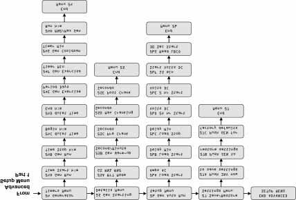
143 Menu Map

144 Navigation
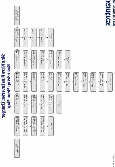
145 Menu Map

146 Navigation
147 6 Basic Setup Programming Chapter 6, Basic Setup Programming explains how to program the Sine Wave Plus Inverter/Charger to operate under basic conditions.
148 Basic Setup Programming Basic Setup Summary Table 6-1 Basic Setup Menu Default Settings Basic Setup Menus The following table provides the default settings for the Sine Wave Plus Basic Setup Menu and the cross-reference pages for locating information on each menu item. If your system requires changes to these default settings, record the changes in Table B-2, Basic Setup Default and User Settings on page B 5 before your start programming. For information on each of the menu items see the corresponding cross-reference page listed in Table 6-1. For directions on how to access the Basic Setup Menu, see Accessing the Basic Setup Menu on page 6 6. Sine Wave Plus 2524 Sine Wave Plus 2548 Range/ Display Default Range/ Display Default 10 Time of Day Setup Menu See 10 Time of Day Setup Menu on page 6 7 for details. 10A Set Hour 00:00:00-23:50:00 10B Set Minute 00:00:00 to 00:09:00 00:00:00 00:00:00-23:50:00 00:00:00 00:00:00-00:09:00 See Page 00:00:00 page :00:00 page C Set Second :00: :00:00 page 6 8 End Menu Inverter Setup Menu See 11 Inverter Setup Menu on page 6 8 for details. 11A High Battery Cut Out Vdc page B Low Battery Cut In Vdc page C Low Battery Cut Out Vdc page D LBCO Delay Minutes page E Search Watts (SRCH) page 6 10 End Menu Battery Charging Menu See 12 Battery Charging Menu on page 6 15 for details. 12A Finish Stage SILENT FLOAT FLOAT SILENT FLOAT FLOAT page B Bulk Volts DC page C Float Volts DC page
149 Table 6-1 Basic Setup Menu Default Settings Basic Setup Summary Basic Setup Menus 12D Equalize Volts DC page E Max Charge Amps AC page F Bulk Done Amps AC page G EQ Vdc Done Timer 00:00-23:50 02:00 00:00-23:50 02:00 page H Max Bulk/EQ Timer 00:00-23:50 05:00 00:00-23:50 05:00 page I Temp Comp End Menu 12 LeadAcid NiCad LeadAcid LeadAcid NiCad 13 AC Inputs Menu See 13 AC Inputs Menu on page 6 22 for details. LeadAcid page A Grid (AC1) Amps AC page B Gen (AC2) Amps AC page C Input Upper Limit Vac page D Input Lower Limit Vac page 6 24 End Menu Save/Restore Settings Menu See 14 Save/Restore Settings Menu on page 6 25 for details. 14A Push INV now to save settings Push INV now to save settings page B Push GEN to restore settings Push GEN to restore settings page C Push GEN for factory defaults End Menu 14 END BASIC SETUP MENU Sine Wave Plus 2524 Sine Wave Plus 2548 Range/ Display Default Range/ Display Default See Page Push GEN for factory defaults page
150 Basic Setup Programming Before You Begin Programming DC Amps verses AC Amps Some items must be pre-determined or confirmed before you start programming the inverter/charger for use. These items include the voltage levels to operate the inverter, charging parameters for the battery charger, and AC input amperage limits. Some of the settings in the Basic Setup Menu may require you to convert DC amps to AC amps. Inverters convert DC power into AC power. Since the DC voltage will be lower than the AC voltage, the DC amps will be higher than the AC amps. The formula or ratio of DC amps to AC amps is the actual AC voltage divided by the actual DC voltage. This ratio is not exact as there will be losses, although small, in the power conversion process. Actual AC Voltage Actual DC Voltage Amp ratio Note: The AC ammeters have an approximate 1 amp tolerance. There are two rules of thumb using this inverter to estimate the amperages. If you are running on battery power: 24 Vdc inverters have about a 5 to 1 ratio of DC amps to AC amps. 48 Vdc inverters have about a 2.5 to 1 ratio of DC amps to AC amps. If you charging battery from AC power: 24 Vdc inverters have about a 4 to 1 ratio of DC amps to AC amps. 48 Vdc inverters have about a 2 to 1 ratio of DC amps to AC amps. For example: A 24 Vdc inverter operating from a battery at 25 Vdc and making 120 Vac will use approximately 4.8 amps DC for every 1 amp AC consumed by the loads (120 Vac/25 Vdc = 4.8) A 48 Vdc inverter charging a battery at 60 Vdc from a generator supplying the inverter with 120 Vac will make approximately 2 amps DC for every 1 amp AC (120 Vac/60 Vdc = 2)
151 Recording Changes Before You Begin Programming Basic Setup Process As you determine the required parameters for this section, check your calculations against the default values shown in Table 6-1, Basic Setup Menu Default Settings on page 6 2. If your configuration requires making changes to the default settings, write the new settings on Table B-2, Basic Setup Default and User Settings, on page B-5. You can then use this table to make initial programming easier and to facilitate reprogramming if ever necessary. Be sure to take the time to get familiar with the basic navigation before you start. See Navigating the Sine Wave Plus on page 5 2 and Menu Heading Buttons on page 5 4, Menu Item Buttons on page 5 4 and Set Point Buttons on page 5 4. The Basic Setup procedure is comprised of the following items: 1. Setting the Time of Day This sets the internal clock for all the features requiring time functions. See 10 Time of Day Setup Menu on page 6 7 for instructions on setting the Time of Day. 2. Selecting Inverter functions This selects basic inverter operating functions. See 11 Inverter Setup Menu on page 6 8 for instructions on setting the Inverter functions. 3. Selecting Charger functions This selects the basic charger functions. See 12 Battery Charging Menu on page 6 15 for instructions on setting the Charger functions. 4. Selecting Grid Usage functions This selects basic Grid Usage functions. See 13 AC Inputs Menu on page 6 22 for instructions on setting the Grid Usage functions. 5. Saving programmed parameters. See 14 Save/Restore Settings Menu on page 6 25 for instructions on setting the Grid Usage functions
152 Basic Setup Programming Accessing the Basic Setup Menu To access the Basic Setup Menu: 1. If you have not already done so, turn on the inverter. 2. Press the button to move forward within the menu headings until the END USER MENU is displayed. 3. Press and hold down the green GEN button. 4. While holding the green GEN button down, press the red INV button to move into the Basic Setup Menu. Power up Display Press the Menu Heading button until the END USER MENU is displayed. Press and hold down the green GEN button. While holding the green GEN button down, press the red INV button to move into the Basic Setup Menu. Figure 6-1 Accessing the Basic Setup Menu
153 Menu Item Descriptions Menu Item Descriptions 10 Time of Day Setup Menu 10 Time of Day Setup Menu This menu allows for setting the time of day in hours, minutes, and seconds. The time is displayed in a 24-hour format (i.e., 00:00:00 to 23:59:59 hours). Important: If the system is being setup for the first time or the DC batteries were disconnected from the inverter, then the time must be reset. The programmed time does not reset when the Press for Factory Defaults button is pressed. To set the time of day: When the BEGIN BASIC SETUP MENU is displayed, press the button to move forward until 10 Time of Day Setup Menu is displayed. 10A Set Hour 10A Set Hour To set the hour display: 1. When the 10 Time of Day Setup Menu is displayed, press the button to select 10A Set Hour. 2. When 10A Set Hour is displayed, press the SET POINT buttons (+) or ( ) to change the time displayed. The "minute" section of the display will change in 10-minute increments. 3. Keep pressing the SET POINT buttons until the appropriate hour is displayed. 10B Set Minute 10B Set Minute To set the minute display: 1. Press the button to select 10B Set Minute. 2. When 10B Set Minute is displayed, press the SET POINT buttons (+) or ( ) to change the time displayed. The "minute" section of the display will change in 1-minute increments. 3. Press the SET POINT buttons (+) or ( ) until the proper minutes are displayed
154 Basic Setup Programming 10C Set Seconds 10C Set Seconds 11 Inverter Setup Menu To set the second display: 1. Press the button to select 10C Set Second. 2. When 10C Set Second is displayed, press the SET POINT buttons (+) or ( ) to change the time displayed. The seconds section of the display will change in 1-second increments. 3. Press the SET POINT buttons (+) or ( ) until the proper seconds are displayed. Seconds will stay fixed as set until you exit the display. 11 Inverter Setup Menu The following inverter settings are intended to protect the batteries from excessive discharging. These settings prevent the inverter from drawing excessive DC voltage from the batteries. To do this, it is necessary to determine the voltage levels where the inverter will start and stop drawing power from the battery bank. The factory default settings for inverter functions are set to protect most types of batteries. It may not be necessary to alter these settings. Before changing the default settings, check with your battery dealer/installer. 11A High Battery Cut Out VDC CAUTION Both 11A High Battery Cut Out (HBCO) and 11C Low Battery Cut Out (LBCO) values lock the upper and lower limits of the inverter/charger and will override and/or readjust other settings programmed. Be sure to recheck and reset, if necessary, all settings affected by changes to 11B Low Battery Cut in VDC, 20A Refloat High Volts DC, 20B Refloat Low Volts DC, 22A High Xfer (HBX) Vdc, 22B Low Xfer (LBX). 11A High Battery Cut Out VDC This voltage level is the maximum voltage the batteries will be allowed to reach. If the battery voltage exceeds this limit for more than 1 minute, the inverter will shut down. The inverter will not support AC loads when in this condition. The inverter automatically restarts when the voltage drops to 3 Vdc (24-volt models) or 6 Vdc (48-volt models) below the HBCO setting. This setting is not temperature compensated
155 11B Low Battery Cut In VDC 11B Low Battery Cut In VDC 11C Low Battery Cut Out VDC Menu Item Descriptions This menu item sets the battery voltage level that turns the inverter back on after being shut down by the LBCO setting. Set this voltage level lower than the Bulk or Float volts DC setting. This voltage level is used to indicate that the batteries have a sufficient level of charge for the inverter to start using power from the battery bank. 11C Low Battery Cut Out VDC When the batteries discharge to the level set in 11C Low Battery Cut Out VDC, and are held at or below this level for the 11D LBCO Delay time, the inverter output shuts down and transfers any available AC source (generator or grid) to the charger to bring the battery level back up to the 11B Low Battery Cut In Vdc level. The inverter will not support any AC loads when in this condition. AC loads will have to be powered by either a generator or grid power. This is the lowest voltage level acceptable for battery use by the inverter. 11D LBCO Delay Minutes 11D LBCO Delay Minutes Menu item 11D LBCO Delay Minutes is used to set the length of time (in minutes) that the inverter is allowed to continuously operate at or below the LBCO level set in menu item 11C Low Battery Cut Out before it shuts off. Once the inverter has shut off, the battery voltage must rise above the value (set in menu 11B Low Battery Cut In) for inverter operation to resume. Guidelines for setting this menu item: If using an automatic generator starting system, do not set this delay period shorter than the amount of time it takes the generator to start and connect. Otherwise, the power will go OFF and then back ON when the generator auto-starts due to the LBCO condition
156 Basic Setup Programming 11E Search Watts 11E Search Watts SRCH This menu item sets the inverter s search sensitivity. Any load that is below this setting does not cause the inverter to produce an AC output voltage when running from batteries. The SRCH function must be selected in 01A Inverter. Note: This item is duplicated for your convenience in menu item 01C and 11E. Changes to settings made at 01C will also change the setting in 11E. Likewise, changes to 11E will also change the setting in 01C. How does Search Sense work Why use search sense How to set up the search mode feature on the inverter While idling in the search sense mode, the inverter sends out a pulse about once per second. This electrical pulse travels through the AC wiring looking for loads that are connected to the system. When a load is detected, the inverter then has to make a decision as to whether or not the load is large enough to bother with. This decision point is user adjustable using the Search Sensitivity control on the inverter. Search sense allows you to selectively power only items that draw more than a certain amount of power, but the bigger reason lies in power savings. For example: Imagine an inverter that has a no load idle power of 8 watts. This means the inverter needs 8 watts to power itself even if no loads are present. If a water pump is driven by the inverter for only one hour total per day then the other twenty-three hours out of the day the inverter is using 8 watts per hour just to sit there and do nothing. That power comes from the batteries. If search sense is set so that the inverter sleeps until the pump wants to run, the scenario described above greatly improves. Now instead of the inverter idling at 8 watts, only ½ watt is drawn while in search mode. This is a savings of 7½ watts per hour or watt-hours. This converts directly to 7 amp-hours for a 24 volt battery system. In systems with small batteries or limited charging capability, this could be a substantial savings. The search sense feature on the inverter is only valuable if the inverter can spend a fair amount of time "sleeping" each day. Therefore, if search sense is to be utilized it must be adjusted properly. The initial adjustment should be made so that the inverter comes on only when needed. The sensitivity control should be adjusted so that the smallest load being run can "wake" the inverter up and cause it to deliver power to the load
157 Menu Item Descriptions If loads change significantly, then re-tuning of the search sensitivity will be required. It may take several adjustments to tweak the sensitivity to just the right point. If problem loads are in the system such as discussed previously, follow the suggestions given to eliminate the problem. Some TV's with instant on circuits have a menu or control to disable it. If clocks are the problem load, consider using battery powered units. If the problem loads just can't be eliminated in one of the suggested manners, there are two work-around solutions: 1. disable the search sense feature, causing the inverter to always remain at full output voltage, or 2. use a search-friendly companion load whose only purpose is to be switched on to wake up the inverter to power the load that is unable to bring the inverter out of search mode. Guidelines for setting this menu item: Setting this mode to 00 disables this function. Default is 08 watts. When the inverter is searching the output for loads, lights that have a wattage lower than this setting, may flash momentarily. Battery Charger Functions Note: Search Mode, by function cannot work with timers or devices that need power 24 hours a day. Examples of devices with timers include coffee makers with brew timers, refrigerators and freezers with defrost timers. Examples of devices that need power 24 hours a day include telephone answering machines, alarm systems, motion detection lights, and some thermostats. When AC power is available, the inverter can operate as a battery charger. Different batteries will require different charging voltage levels. Not charging batteries at the required levels can shorten battery life or possible damage them. It will be necessary to select the voltage levels required and to set the voltage limits for the various stages of charging. Battery charging parameters are set in 12 Battery Charging Menu
158 Basic Setup Programming Important: The default settings of the Sine Wave Plus may or may not work for your specific installation. Take the time to review the default settings to make sure they are appropriate for your installation. If not, you will need to adjust the settings according to the battery manufacturer s recommendations. The following information is provided to help you make the necessary calculations. Multi-Stage Charging Process Note: This information is provided for guidance only. Variations in battery chemistry, as well as, site specific environmental considerations mean that you should consult your system designer or battery manufacturer for specific recommendations for appropriate battery voltage and current settings. The charging cycle uses a multi-stage charging process to maintain the batteries. Whenever AC power that is within the range of the inverter s settings is present at the inverter s input, it passes power through to the connected load and begins charging the batteries, indicated by the Bulk or Float charge indicator LED on the control module. Bulk Stage Absorption Stage Finish Stage Charging Started DC Voltage Increased Voltage Bulk Volts Setting Absorption Time Constant Voltage Float Volts Setting Silent (battery voltage) Reduced Voltage Max Charge Amps Setting BULK DONE AMPS or MAX BULK/EQ TIME If a generator was automatically started by the inverter to charge the batteries, it will shut off when the charger reaches the FINISH stage after the bulk/ absorption period. (GENERATOR must be in AUTO MODE). AC Current Constant Current Reduced Current Reduced Current (Float) No Current (Silent) Time Figure 6-2 Multi-Stage Battery Charging Process
159 Bulk Stage Menu Item Descriptions Bulk charge is the first stage in the charging process and provides the batteries with a controlled, constant current. Once the battery voltage rises to the bulk voltage threshold, the charger switches to the Absorption Stage. Note: If there are DC loads on the batteries, the charger s current may never decrease to a level to initiate the finish stage of charging. To ensure the charger does not stay indefinitely in the bulk stage, set the adjustable timer menu item 12H Max Bulk/EQ Timer h:m to limit the time the batteries are bulk charged. This timing circuit is activated at the start of the Absorption stage and terminates bulk charging if the charge current does not decrease to the setting in menu item 12F Bulk Done Amps AC before the 12H Max Bulk/EQ Timer h:m setting is reached. Absorption Stage Finish Stage Absorption charge is the second stage of battery charging and provides the batteries a controlled, constant voltage for a set period of time. During this stage, the current supplied to the batteries slowly decreases. When this current decreases to or below the setting in menu item 12F Bulk Done Amps AC, the charger switches to the Finish stage. The Finish Stage contains two selections for the final stage of battery charging: Silent or float modes as described below. Float Mode Float charge maintains a trickle charge on the batteries whenever AC is present on the inverter s input. Float charging reduces battery gassing, minimizes watering requirements (for flooded batteries) and ensures the batteries are in a constant state of readiness. When this mode is selected, the charger will automatically switch to the float stage after the batteries have received a bulk and absorption charge. The batteries will be maintained at the level set in menu item 12C Float Volts DC. Note: The battery voltage can increase above the float voltage when using an external charging device such as PV arrays, wind turbines, micro-hydro generators, etc. Be sure to include appropriate charge management equipment with all external DC sources
160 Basic Setup Programming Equalize Charging the Batteries Silent Mode After a bulk and absorption charge cycle is complete, the charger will shut down (go silent). AC voltage on the inverter s input will pass-through to the loads. The charger continues to monitor the battery voltage in this mode and starts a float charge when certain conditions are met: The batteries have discharged below the setting in menu item 20A Refloat Low Volts DC. The battery voltage has increased above the value set in menu 20B Refloat High Volts DC. Notes: When in Silent Mode after entering the Float Charge, the charger remains in the Float Mode until the time set in 20F Must Float Time and the level set in 20E Float Done Amps have been reached. In Silent Mode, the transfer time between utility power and the inverter is slower than in Float Mode. If your application is dedicated to sensitive loads (such as computers), we recommend Float mode. Silent Mode is not recommended for off-grid applications. If the AC input should fail or drops below the lower Vac limit (as set in menu item 13D Input Lower Limit VAC), the complete multi-stage charge cycle (Bulk, Absorption, Finish) will be re-initiated once the source AC returns to an in-tolerance condition. Selecting Silent Mode for the Battery Charging Finish Stage is an Advanced Setup Application and requires additional parameters be established in Menu Heading 20 Silent Setup Menu. Many battery manufacturers recommend periodic equalize charging to level out the voltage between individual cells resulting in better battery performance and life. Over time, the battery s electrolyte can become stratified causing inactive areas in the plate material. If this condition is allowed to continue for extended periods, the battery plates can sulfate and become unusable. Equalizing the batteries is a controlled overcharging method that mixes up the electrolyte and reactivates the unused areas of the plate material, restoring batteries to a full state of charge. Consult the battery manufacturer s recommendation for equalize charging settings
161 Menu Item Descriptions 12 Battery Charging Menu WARNING: Explosion Hazard Only flooded or vented batteries should be equalize-charged. Hydrogen and oxygen gases are produced when batteries are equalize-charged. Provide adequate ventilation and remove all sources of ignition to prevent explosion. CAUTION: Damage to DC Loads and Batteries DC loads should be disconnected from the batteries during equalization charging to protect DC loads from high battery voltages. Equalization was designed for use on standard, liquid electrolyte (lead acid) batteries. Other battery types can be permanently damaged if equalized. If you have sealed or gel cell batteries, do not use the equalization charging function without first checking with the battery manufacturer. Batteries will heat up when equalize charging. Always monitor the battery temperature in 04K Battery Temp Degrees C and shut down the charger if the temperature exceeds the manufacturer s specifications. The BTS must be installed for the inverter to monitor battery temperature. 12 Battery Charging Menu Battery Charging parameters are programmed in 12 Battery Charging Menu, using the following menu items. Some of the menu items will require making calculations. Others just require making selections between the setpoints. The voltage level settings should be adjusted with the battery at a reference temperature of 25 C. Important: Please consult your system designer or battery manufacturer for specific battery charging recommendations
162 Basic Setup Programming 12A Finish Stage 12A Finish Stage Silent Float This menu item determines the Charging Mode (Silent or Float) after the bulk and absorption charge have finished. Select either mode depending on your installation. See Float Mode on page 6-13 for additional information. Additional programming will be required if Silent Mode is selected. See 20 Silent Setup Menu on page 7 8 for additional information on the Silent Mode programming. 12B Bulk Volts DC 12B Bulk Volts DC This is the voltage level at which the charger switches to the absorption stage. The charger will use up to the parameter set in 12E Max Charge Amps AC until the parameter set in 12B Bulk Volts DC is reached. The actual battery charging voltage will be adjusted from this value when the BTS is used. See Table 6-2, Battery Voltages For Setting Charging Parameters on page 6 17 for recommended bulk voltages. 12C Float Volts DC 12C Float Volts DC This is the voltage level at which the charger will maintain the batteries after a bulk and absorption charge. The actual battery charging voltage will be adjusted from this value when the BTS is used. See Table 6-2, Battery Voltages For Setting Charging Parameters on page 6 17 for recommended float voltages. 12D Equalize Volts DC 12D Equalize Volts DC This the voltage level at which the charger performs an equalize charge on the batteries. The factory default setting is the same as the 12B Bulk Volts DC settings. This is to prevent accidental damage to batteries from an unintentional equalize charge. The actual battery charging voltage will be adjusted from this value when the BTS is used. Guidelines for setting this menu item: Be sure to adjust the equalize voltage level up or down depending upon your battery chemistry and whether or not you desire an equalize charge on the system. If this feature is not desired, set this parameter to be identical to the 12B Bulk Volts DC setting. See Table 6-2, Battery Voltages For Setting Charging Parameters on page 6 17 for recommended voltages for equalize charging
163 Menu Item Descriptions Table 6-2 Battery Voltages For Setting Charging Parameters Battery Type BULK VOLTS 24-volt models 48-volt models FLOAT VOLTS 24-volt models 48-volt models Equalization Charge Process Set Temp Comp Sealed Gel Lead Acid AGM Lead Acid Maintenance-Free RV/Marine Lead Calcium Battery Deep-cycle, Liquid Electrolyte Lead Antimony Battery NiCad or NiFe Alkaline Battery (using 10 cells in series) 28.2 Vdc 56.4 Vdc 27.2 Vdc 54.4 Vdc Not recommended - consult manufacturer 28.8 Vdc 57.6 Vdc 26.8 Vdc 53.6 Vdc Charge to 31.0 Vdc (24-volt models) or 62 Vdc (48-volt models) or as per manufacturer recommendations 28.8 Vdc 57.6 Vdc 26.8 Vdc 53.6 Vdc Not recommended - consult manufacturer 29.2 Vdc 58.4 Vdc 26.8 Vdc 53.6 Vdc Charge to 31.0 Vdc (24-volt models) or 62 Vdc (48-volt models) or as per manufacturer recommendations 32.0 Vdc 64.0 Vdc 29.0 Vdc 58.0 Vdc Consult Manufacturer LeadAcid LeadAcid LeadAcid LeadAcid NiCad The following settings (Table 6-3) are guidelines only. Refer to your battery vendor for specific settings and battery maintenance guidelines. Table 6-3 Battery Charging Current and Timer Default Settings Menu Item SW Plus 2524 Default Settings SW Plus 2548 Default Setting 12E Max Charge Amps 20 amps 20 amps 12F Bulk Done Amps AC 10 amps 10 amps 12G EQ Vdc Done Timer h:m 02:00 02:00 12H Max Bulk/EQ Timer h:m 05:00 05:00 12I Temp Comp LeadAcid LeadAcid
164 Basic Setup Programming 12E Max Charge Amps AC 12E Max Charge Amps AC Calculating Maximum Charging Amps This is the maximum AC amperage the inverter will provide to the battery charger to get the battery voltage up to the level set in one of the following menu items depending on which mode the battery charger is in as indicated by the LEDs on the inverter s display: 12B Bulk Volts DC, 12C Float Volts DC, or 12D Equalize Volts DC. Use menu 12E Max Charge Amps AC to reduce the charging current to 10% (or less) of the battery capacity. Guidelines for setting this menu item: Small battery banks may overheat if charged at too high of a current. Setting this value higher than the default and continuously drawing the maximum current may put the inverter in an Overtemp Error condition. The following settings are guidelines only. Refer to your battery vendor for specific settings and battery maintenance guidelines. To calculate the 12E Max Charge Amps AC: 1. Multiply the battery amp hours by 10%. This is the DC Maximum Charge Rate. 2. Convert the DC Maximum Charge Rate to AC amps by dividing the DC Maximum Charge Rate by 3.5 for a 24-volt system or 1.75 for a 48-volt system. 3. The result is the approximate amp setting that should be entered for the 12E Set Max Charge Amps AC menu item. For stacked inverters, use half the battery amp hour rating in the calculations. Table 6-4 Calculating the Maximum Charge Amps for a 24-volt, 700 amp-hour Battery Step Instruction Equation 1 Multiply the total battery amp hours by 10% 700 x 10% = 70 (DC Max Charge Rate) 2 Divide the DC Max Charge Rate by = 20 3 Set the 12E Max Charge Amps AC 20 parameter
165 12F Bulk Done Amps AC Menu Item Descriptions Table 6-5 Calculating the Maximum Charge Amps for a 48-volt, 350 amp-hour Battery Step Instruction Equation 1 Multiply the total battery amp hours by 10% 2 Divide the DC Max Charge Rate by Set the 12E Max Charge Amps AC parameter. 350 x 10% = 35 (DC Max Charge Rate) = F Bulk Done Amps AC This is the AC current threshold where the battery charger will transfer from Absorption Charging to Finish Charging. It is recommended to set this value at 2 4% of the battery bank s total amp-hour capacity. Guidelines for setting this menu item: Setting the 12F Bulk Done Amps AC to 0 (zero) will keep the charger in the Bulk Mode until the setting in 12G Max Bulk/EQ Timer h:m is reached. If there are any DC loads connected to the batteries (and are actively drawing current), this additional current must be added to the 12F Bulk Done Amps AC setting (after conversion from DC amps). If this additional current is not accounted for, the charger will continue to charge at the bulk voltage until the 12G Max Bulk/EQ Timer h:m period is reached and switches the charger out of the bulk stage. To calculate the 12F Bulk Done Amps AC: 1. Multiply the battery amp hours by 2% to 4%. This is the AC Bulk Done Charge Rate. 2. Convert the AC Bulk Done Charge Rate to AC amps by dividing the AC Bulk Done Charge Rate by 4 for a 24-volt system or 2 for a 48-volt system. 3. The result is the approximate amp setting that should be entered for the 12F Bulk Done Amps AC menu item. For stacked inverters, use half the battery amp hour rating in the calculations
166 Basic Setup Programming 12G EQ VDC Done Timer Table 6-6 Calculating the Bulk Done Amps for a 24-volt, 700 amp-hour Battery Step Instruction Equation 1 Multiply the total battery amp hours by 2% (3%, 4%) 2 Divide the AC Bulk Done Charge Rate by 4 3 Set the 12F Bulk Done Amps AC parameter. 700 x 2% (3%, 4%) = 14 (21, 28) (AC Bulk Done Charge Rate) 14 4 = 3.5 (for 2%) 21 4 = 4 (for 3%) 28 4 = 7 (for 4%) 3 to 7 amps AC Table 6-7 Calculating the Bulk Done Amps for a 48-volt, 350 amp-hour Battery Step Instruction Equation 1 Multiply the total battery amp hours by 2% (3%, 4%) 2 Divide the AC Bulk Done Charge Rate by 2 3 Set the 12F Bulk Done Amps AC parameter. 350 x 2% (3%, 4%) = 7 (10.5, 14) (AC Bulk Done Charge Rate) 7 2 = 3.5 (for 2%) = 5.25 (for 3%) 14 2 = 7 (for 4%) 3 to 7 amps AC 12G EQ VDC Done Timer h:m This is the maximum time the batteries will be allowed to charge at the equalize voltage level set in 12D Equalize Volts DC. This setting is limited by 12H Max Bulk/EQ Timer h:m, which sets the maximum period for the EQ charge stage. This is a safety feature that ensures that abnormal conditions will not cause the charger to hold the batteries at high voltages for prolonged periods of time. This timer starts when the EQ voltage is reached as set in menu item 12D Equalize Volts DC
167 Menu Item Descriptions 12H Max Bulk/EQ Timer h:m 12H Max Bulk/EQ Timer h:m This is the maximum time the charger is allowed to keep the batteries in the Bulk or EQ Charge Stage. This timer starts when either the Equalize Charge starts or when the Bulk Charge starts. Ensure this setting doesn't interfere with the 12G EQ Vdc Done Timer h:m or the 12F Bulk Done Amps AC settings. Guidelines for setting this menu item: Check menu item 04J Max Bulk/EQ Time h:m (see page 8 24 for information) for the amount of time the charger has been in the Bulk or EQ charge stage. This is a safety feature ensuring that abnormal conditions (i.e., DC loads connected to the batteries) will not cause the battery charger to hold the batteries at high voltage levels for prolonged periods of time. As a protection feature, this timer overrides settings programmed in 12F Bulk Done Amps AC and 12G EQ Vdc Done Timer menu items. 12I Temp Comp 12I Temp Comp LeadAcid NiCad This menu item provides for the selection of the appropriate temperature compensation for your particular battery type. Temperature compensation reduces the battery charge voltage when the environmental temperature is hot to prevent battery over-gassing or overcharging. In cold temperatures, the voltage is increased to assure complete battery charging. Temperature compensation only occurs if the BTS is installed. The plug-in external BTS automatically fine tunes the charging process of the SW Plus inverter. When the BTS is installed, the battery charging set points (12B Bulk Volts DC, 12C Float Volts DC, and 12D Equalize Volts DC) are automatically adjusted based on the temperature of the battery being 25 C (77 F). Actual charging voltage may vary above or below these setting due to adjustments for battery temperature. The Sine Wave Plus inverter adjusts the bulk, float, and equalizing set point by 60 mv for 24 Vdc systems and 120 mv for 48 Vdc systems per degree Celsius for the LeadAcid temperature compensation setting. For the NiCad setting, the inverter adjusts the set points by 40 mv for 24 Vdc systems and 80 mv for 48 Vdc systems per degree Celsius. If the wiring to the sensor is damaged and the wires are shorted or cut, the inverter will charge at non-temperature compensated settings and the inverter may not charge as expected
168 Basic Setup Programming Temperature compensation calculations are derived from the following table: Table 6-8 Inverter Temperature Compensation Calculation using the BTS Battery Type 24-volt Systems 48-volt Systems Lead Acid NiCad volts (60 mv) per degree Celsius volts (40 mv) per degree Celsius Volts (120 mv) per degree Celsius volts (80 mv) per degree Celsius Temperature compensation is based on battery type: 5 mv/cell for Lead Acid type batteries and 2 mv/cell for alkaline type batteries (NiCad or NiFe). 13 AC Inputs Menu Note: If the battery temperature is allowed to fall to extremely cold temperatures, the inverter with a BTS may not be able to properly recharge cold batteries due to maximum voltage limits of the inverter. Ensure the batteries are protected from extreme temperatures. The default for this menu item is LeadAcid. This setting only needs to be changed if using NiCad or Alkaline type batteries. Before changing the default settings, check with your battery manufacturer. 13 AC Inputs Menu The AC input parameters establish the voltage settings and current limits for AC power usage. AC input is the AC power that the inverter draws on to either power the loads (pass through) or power the battery charger. AC power can be provided by the utility grid or an AC generator. These settings provide the limit at which the inverter will start drawing power from the batteries in order to meet the demand of the AC loads. Configuring the AC inputs includes determining the following parameter values. These settings are programmed into 13 AC Inputs Menu under the following menu items: 13A Grid (AC1) Amps 13B Gen (AC2) Amps 13C Input Upper Limit Vac 13D Input Lower Limit Vac
169 13A Grid (AC1) Amps AC 13A Grid (AC1) Amps AC 13B Gen (AC2) Amps AC Menu Item Descriptions This is the maximum amount of current that can be drawn from the grid (AC1 input) by the loads and battery charger combined. This settings determines the amperage level at which point the inverter starts drawing power from the batteries to add to the utility power to meet the demand of the loads. This is the AC load support feature. If the loads exceed this setting, the inverter will draw from the batteries and add it to the utility power to meet the demand of the loads. Typically, this value is set to the size of the AC circuit breakers feeding the inverter's AC input. 13B Gen (AC2) Amps Ac This is the maximum amount of current that can be drawn from the generator (AC2 input) by the loads. This settings determines the amperage level at which point the inverter starts drawing power from the batteries to add to the generator power to meet the demand of the loads. This is the AC load support feature. If the loads exceed this setting, the inverter will draw from the batteries and add it to the generator power to meet the demand of the loads. Typically, this value is set to the size of the generator's AC circuit breaker feeding the inverter's input or the maximum output amperage capacity of the generator. This setting is very depended on the performance of the generator. Other factors such as altitute, line losses between the generator and the inverter will require lowering this setting to below what the generator is rated for. For best results, begin with a setting half your expected generator current capacity and gradually increase this setting while verifying the AC voltage on the AC2 inverter terminals stays at lease several volts above the 13D Input Lower Limit VAC setting
170 Basic Setup Programming 13C Input Upper Limit VAC 13C Input Upper Limit VAC This menu item sets the highest voltage at which the inverter is allowed to connect to either AC1 or AC2 inputs. When this voltage is reached the inverter disconnects from the grid or generator and provides power to the loads from the batteries as long as the inverter selection in menu 01A Inverter is ON or SRCH. The inverter reconnects to the AC source when the voltage drops below this setting. Guidelines for setting this menu item: Ensure this value is within the upper limits of any AC operated equipment connected to the inverter. 13D Input Lower Limit VAC 13D Input Lower Limit VAC This menu item sets the lowest voltage at which the inverter is allowed to connect to either AC1 or AC2 inputs. This setting determines the voltage level at which point the inverter starts drawing power from the batteries to aid to the grid power (AC1) or GEN (AC2) power depending on which one is being used to meet the demands of the loads. When the AC voltage reaches this level, the inverter stops battery charging and operates in parallel (in the inverter mode) with the AC source, to aid the utility power to meet the demands of the load. This reduces the loading effect on the AC source. If the voltage drops below this level, the inverter disconnects the AC source and powers the load directly from the batteries as long as the inverter s selection in 01A Inverter is ON or SRCH. This is part of the AC support feature. Guidelines for setting this menu item: Ensure this value is within the lower limits of any AC operated equipment connected to the inverter. CAUTION: Damage to Loads Adjusting upper and lower AC voltage parameters allows the higher and lower voltages than the inverter output to pass through to connected AC loads. Ensure that all connected AC loads will not be damaged by the higher and lower settings
171 14 Save/Restore Settings Menu Menu Item Descriptions 14 Save/Restore Settings Menu This menu provides the means to: save user programmed settings, restore previously saved programmed settings, or to restore factory default settings. If DC power is removed from the inverter, all user defined setpoints will be intact if they were saved before the power was removed. If new settings are not saved, the inverter will restart with the last saved setpoints or with the factory defaults (if none were ever saved). 14A Push INV now to Save Settings Note: The settings in this menu are identical to Menu 27. Saving or restoring settings at either menu will apply to all menu settings (Basic and Advanced). 14A Push INV now to save settings This menu item provides the means to save settings currently programmed into the inverter. To save settings: 1. Press the button until 14A Push Inv Now to Save Settings is displayed. 2. Press the red INV button to save the settings. 14B Push GEN to Restore Settings 14B Push GEN to restore settings This menu item provides the means to restore settings previously set and saved on the inverter. To restore settings previously programmed into the inverter: 1. Press the button until 14B Push Gen to Restore Settings is displayed. 2. Press the green GEN button to restore previously programmed settings
172 Basic Setup Programming 14C Push GEN for factory defaults 14C Push GEN for factory defaults This menu item provides the means to restore the factory default settings. To restore the factory default settings: 1. Press the button until 14C Push Gen For Factory Defaults is displayed. 2. Press the green GEN button to restore the factory default settings. End Basic Setup Menu END BASIC SETUP MENU You have reached the end of the Basic Setup Menu. To exit the Basic Setup Menu and go on to the Advanced Setup Menu: 1. Press the Menu Heading button until END BASIC SETUP MENU is displayed. 2. Press the green GEN button and hold it down. 3. While holding down the green GEN button, press the red INV button. This will move you forward to the ADVANCED USER SETUP MENU
173 7 Advanced Setup Chapter 7, Advanced Setup explains how to program the Sine Wave Plus Inverter/Charger to operate under special, advanced conditions, such as automatic generator starting, energy management and auxiliary load applications.
174 Advanced Setup Advanced Setup Summary The following table provides the default settings for the Sine Wave Plus Advanced Setup Menu and cross-reference pages for locating information on each menu item. If your system requires changes to these default settings, record the changes in Table B-3, Advanced Setup Default and User Settings on page B 7 before your start programming. For information on each of the Menu Items see the corresponding cross-reference page listed in Table 7-1. For directions on how to get to the Advanced Setup Menu, see Accessing the Advanced Setup Menu on page 7 6. Table 7-1 Advanced Setup Menu Headings and Default Settings Advanced Setup Menus Sine Wave Plus 2524 Sine Wave Plus 2548 Range/ Display Default Settings Range/ Display Default Settings 20 Silent Setup Menu See 20 Silent Setup Menu on page 7 8 for details. See Page 20A Refloat High Volts DC page B Refloat Low Volts DC page C Float Done Amps AC page D Must Float Time Min page 7 10 End Menu Grid AC1 Usage Menu See 21 Grid (AC1) Usage Menu on page 7 11 for details. 21A Grid Usage SB BX SB SB BX SB page B Grid Usage Begin h:m 00:00-23:50 21:00 00:00-23:50 21:00 page C Grid Usage End h:m 00:00-23:50 21:00 00:00-23:50 21:00 page 7 13 End Menu Battery Xfer (BX) Menu See 22 Battery Xfer (BX) Menu on page 7 13 for details. 22A High Xfer (HBX) Vdc page B Low Xfer (LBX) Vdc page 7 14 End Menu ALM Relays Menu See 23 ALM Relays Menu on page 7 14 for details. 23A RY9 VDC Energized page B RY9 VDC DeEnergized page
175 Table 7-1 Advanced Setup Menu Headings and Default Settings Advanced Setup Summary Advanced Setup Menus 23C RY9 Delay at DeEngz. Min page D RY10 VDC Energized Vdc page E RY10 VDC DeEnergized Vdc page F RY10 Delay at DeEngz. Min page G RY11 Mode End Menu 23 Cooldown Error Error Cooldown Error Error page Generator Timers Menu See 24 Generator Timers Menu on page 7 22 for details. 24A Gen Run Time Start h:m 00:00-23:50 08:00 00:00-23:50 08:00 page B Gen Run Time Stop h:m 00:00-23:50 08:00 00:00-23:50 08:00 page C Quiet Time Begin h:m 00:00-23:50 08:00 00:00-23:50 08:00 page D Quiet Time End h:m 00:00-23:50 08:00 00:00-23:50 08:00 page E Gen Exercise Period Days page F Gen Exercise Timer Min page G Gen Cooldown Timer Min page H RN2/Max Gen Run h:m 00:00-23:50 08:00 00:00-23:50 08:00 page 7 24 End Menu Gen Starting Details Menu See 25 Gen Starting Details Menu on page 7 24 for details. 25A RY7 Mode GS RN1 RN2 GS GS RN1 RN2 GS page B Gen Warm-up Second/Minute / Seconds / Seconds page C Pre Crank Seconds page D Max Cranking Seconds page E Post Crank Seconds End Menu 25 Sine Wave Plus 2524 Sine Wave Plus 2548 Range/ Display Default Settings Range/ Display Default Settings 26 Gen Auto Run Setup Menu See 26 Gen Auto Run Setup Menu on page 7 33 for details. See Page 26A Load Start Amps AC s page B Load Start Delay Min page
176 Advanced Setup Table 7-1 Advanced Setup Menu Headings and Default Settings Advanced Setup Menus 26C Load Stop Delay Min page D 24 hr Start Volts DC page E 2 hr Start Volts DC page F 15 min Start Volts DC page G Read LBCO 30 sec Start End Menu 26 LBCO setting (11C) 22.0 Read Only LBCO setting (11C) 44.0 Read Only page Save/Restore Settings Menu See 27 Save/Restore Settings Menu on page 7 34 for details. 27A Push INV now to save Settings Push INV now to Save Settings page B Push GEN to restore settings Push GEN to restore settings page C Push GEN for factory defaults End Menu 27 END ADVANCED SETUP MENU Sine Wave Plus 2524 Sine Wave Plus 2548 Range/ Display Default Settings Range/ Display Default Settings See Page Push GEN for factory defaults page
177 Before You Begin Advanced Programming Record your Changes Before You Begin Advanced Programming The Sine Wave Plus is designed to provide advanced application programming. Advanced applications include: SILENT SETUP - Sets the parameters for the Silent finish stage of battery charging. This feature is programmed in Menu Heading 20. See 20 Silent Setup Menu on page 7 8 for information on programming this feature. GRID USAGE - Sets parameters for when and how the utility grid is used. It supports energy management applications such as Time-of- Use Metering and Peak Load Shaving (SB Mode). It also controls transfer of grid power to protect the batteries (BX Mode).These features are programmed in Menu Heading 21 and 22. See 21 Grid (AC1) Usage Menu on page 7 11 and 22 Battery Xfer (BX) Menu on page 7 13 for information on programming this features. AUXILIARY LOADS - Sets the parameters by which the relays in the ALM are used. This feature is programmed in Menu Heading 23. See 23 ALM Relays Menu on page 7 14 for information on programming these parameters. GENERATOR CONTROL AND SUPPORT - Sets the parameters for starting a generator based on time, type of generator being used, and the inverter s voltage and current. This feature is programmed in Menu Headings 24, 25 and 26. See 24 Generator Timers Menu on page 7 22 for information on programming the generator to run based on time settings. See 25 Gen Starting Details Menu on page 7 24 for information on programming the generator to run based on type of generator being used. See 26 Gen Auto Run Setup Menu on page 7 33 for information on programming the generator to run based on voltage or current settings. SAVING/RESTORING SETTINGS - Saves or restores previously programmed user settings. This feature can also restore factory defaults. If your configuration requires making changes to the default settings as listed in Advanced Setup Menu Headings and Default Settings on page 7 2, write the new settings on Table B-3, Advanced Setup Default and User Settings on page B 7. You can then use this table to make initial programming easier and to facilitate reprogramming if ever necessary
178 Advanced Setup Accessing the Advanced Setup Menu To access the Advanced Setup Menu from the User Menu: 1. Press the button to move forward within the Menu Headings until the END USER MENU is displayed. 2. Press and hold down the green GEN button. 3. While holding the green GEN button down, press the INV to move into the BEGIN BASIC SETUP MENU. 4. Release the GEN and INV buttons. Access the User Menu Press the Menu Heading button until the END USER MENU is displayed. Press and hold down the green GEN button. While holding the green GEN button down, press the red INV button to move into the Basic Setup Menu. Figure 7-1 Accessing the Basic Setup Menu
179 5. From here you can, either Accessing the Advanced Setup Menu a) Press the button to move forward within the Menu Headings until the END BASIC SETUP MENU is displayed. b) Or proceed to Steps 5 and Press and hold down the green GEN button. 7. While holding the green GEN button down, press the red INV to move into the ADVANCDED SETUP MENU. OR Press to scroll through the Basic Setup Menu Headings. Press the green GEN button and hold down. While holding down the green GEN button, push the red INV button. Press the green GEN button and hold down. While holding down the green GEN button, push the red INV button. Figure 7-2 Accessing the Advanced Setup Menu
180 Advanced Setup Menu Item Descriptions 20 Silent Setup Menu 20 Silent Setup Menu When it works How it works This menu is used only when SILENT is selected in menu 12A Finish Stage. When the Silent mode is selected, the charger is turned OFF and does not supply any charging current to the batteries until certain conditions based on battery voltage are met. Silent mode is defined as no inverting or charging and the input AC (if available) will pass-through to the output and is recommended for use only if utility power is the AC source. This menu provides the settings which will maintain the float voltage on the batteries by: Turning ON the charger when the batteries drain to the level set in menu 20B Refloat Low VDC. Attempts to maintain the battery voltage at the float level by diverting the excess power to the loads when the battery voltage increases to the level set in menu 20A Refloat High VDC The battery voltage can only go above the 20A Refloat High VDC limit if an external source is used to provide power to the batteries such as a PV array, wind generator, micro-hydro generator, etc. When this level is met or exceeded, the unit turns on the charger and directs the excess DC power to the AC loads and attempts to maintain the battery at the float voltage level. Whenever one of these conditions is met, the batteries will be maintained at the float level for both: the period of time set in menu 20D Must Float Time, then the level set in menu 20C Float Done Amps AC. The silent mode does not maintain the battery at float voltage all the time. The battery charger only operates if required and the AC power from the utility grid is passed through the inverter to the loads 24 hours a day. This option is recommended only if utility power is the only AC source. After the batteries are given a bulk and absorption charge cycle, the inverter will then go totally silent and will wait for the DC voltage to fall or until utility power fails. If the battery voltage falls, the inverter will allow the AC source to recharge the battery. If there is a power outage, the inverter will perform another bulk and absorption charge cycle and return to the silent mode once the AC source has returned
181 Menu Item Descriptions Silent mode will begin after the charge routine has finished the bulk/ absorption charge and if the silent charge has been selected (from Menu item 12A Finish Stage). After entering the Silent mode, there will be a minimum 60 second delay, then the inverter will monitor the battery voltage to determine if the voltage is at or above the 20A Refloat High Volts DC setting or if the voltage has fallen to or below the 20B Refloat Low Volts DC setting. External charging sources Advantages Disadvantage Summary If the battery voltage has reached one of these refloat Vdc settings (20A Refloat High Volts DC or 20B Refloat Low Volts DC) then the inverter will come out of silent and begin to maintain the batteries at the float voltage level. If the battery voltage tries to fall below the float level, the inverter will use current from the utility grid connected to the AC1 input to continue to maintain the float voltage level. If some external current (renewable energy source) is used to increase the battery voltage above the float voltage level, the inverter will use this excess power above the float voltage requirements to power the inverter output loads. If the external current source provides more current that what is needed to maintain the batteries at the float voltage and power the inverter loads, the battery voltage will rise. The inverter will continue to maintain the batteries at the float voltage level until the 20D Must Float Time Min time has expired and the current (as read on the 04C INV/CHR Amps AC meter display) has fallen below the 20C Float Done Amps setting. At this time, the inverter will return to the Silent mode. If AC power is lost, after it has returned, the inverter will complete another Bulk and Absorption charge to the battery and again return to the silent stage. The advantage of the Silent stage is slightly less power consumption under most conditions and quieter operation since the battery charger is off most of the time. The disadvantages of Silent charge is the loss of the natural power conditioning ability of the inverter, the ability to provide the AC load support (except during the time that the inverter is charging) and a longer transfer to inverter power from the loss of utility power. These disadvantages are only present when the inverter is not charging batteries. Silent comes on based on DC volts as programmed in 20A Refloat High Volts DC and 20B Refloat Low Volts DC (after 60 second delay) Silent goes off based on time 20D Must Float Time Min, then amps 20C Float Done Amps
182 Advanced Setup 20A Refloat High Volts DC Note: This information is provided for guidance only. Variations in battery chemistry, as well as site specific environmental considerations, mean that you should consult your system designer or battery manufacturer for specific recommendations for appropriate battery voltage and current settings. An amp-hour meter (e.g., Xantrex TM500A) would be useful to verify your settings are correct to maintain a proper charge on the batteries. 20A Refloat High Volts DC This menu item sets the upper battery voltage level that triggers the float charge. When this level is met or exceeded, the unit turns on the charger and directs the excess DC power to the AC loads and attempts to maintain the battery at the float voltage level. 20B Refloat Low Volts DC 20B Refloat Low Volts DC This menu item sets the lower battery voltage level to which the batteries are allowed to discharge. When the batteries drop to or below this level the charger will turn ON and provide a float charge to the batteries. It will not initiate a bulk charge. 20C Float Done Amps AC 20C Float Done Amps AC This menu item is used by the charger to determine the AC current level (after the 20D Must Float Time Min period has been reached) when it should change back to the Silent mode. As the batteries charge, their current demands decrease. This setting specifies at what point the current supplied to the batteries is allowed to decrease to in order to trigger the Silent mode. The 20C Float Done Amps AC setting is usually set to 1% of the total battery bank capacity. To calculate the 20C Float Done Amps AC: 1. Multiply the battery amp hours by 1%. This is the DC Max Charge Rate changed to float done amps expressed in DC terms. 2. Convert the DC Max Charge Rate to AC amps by dividing the DC Max Charge Rate by 4 for a 24-volt system or 2 for a 48-volt system. 3. The result is the approximate amp setting that should be entered for the 20C Float Done Amps AC menu item. For stacked inverters, use half the battery amp-hour rating in the calculations
183 20D Must Float Time Min Menu Item Descriptions Table 7-2 Calculating the Float Done Amps for a 24-volt, 700 amp-hour Battery Step Instruction Equation 1 Multiply the total battery amp hours by 1% 2 Divide the DC Max Charge Rate by 4 3 Set the 20C Float Done Amps AC parameter. 700 x 1% = 7 (DC Max Charge Rate) 7 4 = 1 1 amps AC Table 7-3 Calculating the Float Done Amps for a 48-volt, 350 amp-hour Battery Step Instruction Equation 1 Multiply the total battery amp hours by 1% 2 Divide the DC Max Charge Rate by 2 3 Set the 20C Float Done Amps AC parameter. 350 x 1% = 3.5 (DC Max Charge Rate) = 1 1 amps AC 20D Must Float Time Min This menu item sets the minimum amount of time after the 20A Refloat High Volts DC and 20B Refloat Low Volts DC settings have been reached that the inverter will maintain the float voltage level on the batteries before it reaches the 20C Float Done Amps AC setting and returns to the Silent mode. 21 Grid (AC1) Usage Menu 21 Grid AC1 Usage Menu This menu sets the conditions that determine how and when the inverter s AC1 (grid) input will be used. To program grid usage parameters, the Advanced Setup Menu Headings 21 Grid (AC1) Usage Menu and 22 Battery Xfer Menu are used
184 Advanced Setup 21A Grid Usage 21A Grid Usage SB BX This menu item allows you to select between the set points SB and BX as described below. SB (Standby) - Utility Backup This set point is the first set point selection in the 21A Grid Usage menu. It sets the inverter to be used as a backup power supply. When AC power is available at the inverter s AC1 input, the batteries are maintained until the AC power is lost. At which point, the inverter supplies AC power to the load from the batteries. This is the default setting for grid usage. This mode also allows for energy management features such as Time-of-Use Metering and Peak Load Shaving which are programmed in menu items 21B Grid Usage Begin h:m and 21C Grid Usage End h:m. See Energy Management on page 2 44 for information regarding Energy Management Features. BX (Battery Transfer) - Renewable Energy Backup This set point is the second selection in 21A Grid Usage and works in conjunction with Menu Heading 22 Battery Xfer (BX). It allows the batteries to power the AC loads until the batteries discharge to the settings in menu 22B Low Xfer (LBX) VDC and then transfers to the utility. Utility grid power is then used as a backup source to keep the loads powered. When the batteries have recharged from an external DC source to the setting in menu 22A High Xfer (HBX) VDC, the inverter transfers from the utility grid back to inverter supplied AC power. Guidelines for setting this menu item: In the BX mode the batteries will only be charged from the DC source, not by the Sine Wave Plus. The utility grid is only used to pass-through the AC to the loads when the batteries are discharged to a preset level. The BX Mode and Grid Usage Timer are not optimized to work together. These two features can have different priorities and may conflict with each other. 21B Grid Usage Begin h:m 21B Grid Usage Begin h:m This menu sets the daily begin time when the inverter is allowed to be connected to the grid. This timer is only used when SB is selected in 21A Grid Usage. When the timer allows the inverter s AC1 input to connect to the grid, the inverter samples the utility grid power, and if within acceptable tolerances, starts to charge the batteries at the bulk then float voltage levels or Silent (based on the selection made in menu item 12A Finish Stage
185 The clock is in a 24 hour format (00:00 to 23:59 hours). Guidelines for setting this menu item: Menu Item Descriptions Ensure the current time is set correctly in menu 10 Time Of Day Setup Menu. The timer function is deactivated if the 21C Grid Usage Begin h:m is the same as the 21D Grid Usage End h:m time. This setting only operates with the AC1 input (Grid Input). 21C Grid Usage End H:M Note: The Grid Usage Timer feature is designed to work with the SB Mode, selected under the 21A Grid Usage menu, and is enabled by setting the 21B Grid Usage Begin h:m and 21C Grid Usage End h:m times differently. If BX Mode is selected and the Grid Usage Timer is also enabled, the results cannot be guaranteed as these two features can have conflicting priorities (i.e., to use or not use grid power.) 21C Grid Usage End h:m This menu sets the time the inverter stops using the grid to charge the batteries or power the loads. This timer is only used when SB is selected in menu 21A Grid Usage. Guidelines for setting this menu item: Ensure the current time is set correctly in menu 10 Time Of Day Setup Menu. The timer function is deactivated if the 21C Grid Usage Begin h:m is the same as the 21D Grid Usage End h:m time. This setting only operates with the AC1 input (grid input). 22 Battery Xfer (BX) Menu 22 Battery Xfer (BX) Menu This menu heading provides settings that determine the transfer levels when the loads will be powered from the inverter or from the utility power (pass-through only). These menu items are only used when BX is selected in menu 21A Grid Usage. Guidelines for setting this menu item: These settings only operate with the AC1 input (grid input). The upper and lower ranges of these settings are locked by the set point levels in Menus 11A High Battery Cut Out VDC and 11C Low Battery Cut Out
186 Advanced Setup 22A High Xfer (HBX) VDC 22A High Xfer (HBX) VDC 22B Low Xfer (LBX) VDC 22B Low Xfer (LBX) VDC 23 ALM Relays Menu This menu is used to set the voltage transfer point when the inverter turns back on and resumes powering the AC loads from the batteries. When this setting is reached, the inverter transfers from the AC1 input (grid) to the batteries to power the loads. An external DC charging source (wind, solar, etc.) must raise the battery voltage above this setting before the system resumes inverter operation. There is no delay in transferring from the grid to the inverter after the battery voltage reaches this level. This setting is not temperature compensated. This menu is used to set the voltage transfer point from the batteries to the AC1 input (grid) due to a low battery condition. The transfer occurs only if the battery voltage reaches or remains below this setting for 10 seconds. The system returns to powering the AC loads from the battery once the battery voltage increases to the level set in menu 22A High Xfer (HBX) VDC above. This setting is not temperature compensated. 23 ALM Relays Menu Auxiliary Load functions are controlled by setting parameters in Menu Heading 23 ALM Relays. Using this feature requires the additional purchase of a Xantrex ALM. The ALM can be used to operate auxiliary loads such as water pumps or alarms. The two auxiliary relays operate independently of the inverter/ charger status (inverter being ON or OFF). As long as the control circuit is powered, as evident by the text on the ICM LCD screen being visible, the AUX relays will operate. Two voltage-controlled relays (RY9 and RY10) and an AC Output Fault Relay (RY11) are provided on the optional ALM. RY9 RY9 (load control relay) is dedicated for use as a load control relay to prevent battery discharge and is not temperature compensated for the battery. This relay operates in both the inverter and charger modes. RY10 RY10 (charge control relay) is dedicated as a control relay for regulating either a source of DC power or for controlling a load to utilize excess power from DC sources. This relay is temperature compensated and uses the 04B Battery Comp VDC display to determine its DC value. This relay operates in both the inverter and charger modes
187 23A RY9 VDC Energized 23A RY9 VDC Energized 23B RY9 VDC DeEnergized 23B RY9 VDC DeEnergized 23C RY9 Delay At DeEngz. Min 23C RY9 Delay at DeEngz. Min 23D RY10 VDC Energized 23B RY10 VDC Energized Menu Item Descriptions RY11 RY11, when ERROR is selected, is used as an inverter error detection indicator device to display or sound an alarm when the inverter AC output is lost. If COOLDOWN is selected, this will allow both inverters to have a cooldown period when used in a series-stacked configuration. This menu item sets the voltage trip point for relay RY9. When the battery voltage reaches or exceeds this setting, the relay closes (energizes) between the N.O. and COM terminals. There is a 2-second time delay on the reaction of this setting, allowing fast response to rapid voltage changes in the system. This setting is not temperature compensated when a BTS is installed. This menu item sets the voltage trip point for the auxiliary relay RY9. When the battery voltage drops to or below this setting for the variable time period set in menu 23C RY9 Delay At DeEngz. Min, the relay deenergizes and closes the contacts between the N.C. and COM terminals. This setting is not temperature compensated when a BTS is installed. This menu item sets the delay time period in minutes at which the voltage level must remain at or below before relay RY9 is deenergized. This is an active low type of control. The relay closes between the N.C. and COM terminals when the battery voltage falls to or below the level set in menu 23B RY9 VDC DeEnergized for the time period set here. This menu item sets the voltage trip point for the auxiliary relay RY10. When the battery voltage, based on the 04B Battery Comp VDC display, rises to or above this setting for the time period set in menu 23F RY10 Delay At Engz. Min, the relay energizes and closes the contacts between the N.O. and COM terminals. This setting is temperature compensated when the optional BTS is installed
188 Advanced Setup 23E RY10 Vdc DeEnergized 23E RY10 Vdc DeEnergized 23F RY10 Delay at Engz. Min 23F RY10 Delay at Engz. Min This menu item sets the trip point where the relay de-energizes. When the voltage, based on the 04B Battery Comp VDC display, drops to or below this setting, the relay de-energizes and opens the contacts between the N.O. and COM terminals immediately. There is no time delay on the reaction of this setting, allowing fast response to rapid voltage changes in the system. This setting is temperature compensated when a BTS is installed and operates in both inverter and charger modes. This menu item sets the delay time period in minutes at which the voltage level must remain at or below before relay RY10 is deenergized. This is an active low type of control. The relay closes when the battery voltage falls to or below the level set in menu 23E RY10 VDC DeEnergized for the time period set here. 23G RY11 Mode 23G RY11 Mode Cooldown Error These two settings allow the RY11 relay in the ALM or GSM to function differently based on your selection. Cooldown In a multiple Sine Wave Plus inverter installation and using the inverter s automatic generator feature, you can use the cooldown selection to enable an external contactor to allow both legs of a generator to go through a cooldown period. When using the generator AUTO selection and connecting two inverters in a series stacked installation (for 120/240Vac operation), the inverter that controls the generator will disconnect from the generator to allow a cooldown period prior to stopping the generator. The other inverter not controlling the generator does not know the generator is about ready to be stopped; so it can not disconnect from the generator to allow this leg a cooldown period. Selecting cooldown under RY11 mode and using the RY11 relay to control an external contactor - that feeds both inputs to the inverters - will allow both legs of the generator to be disconnected and unloaded at the same time and go thru the cooldown period prior to shutting down. See Figure 7-3 on page 7 17 for the installation diagram using this feature. Error This selection allows the RY11 relay to function as an Error Detection Relay. The blue LED (controlled by the RY11 relay) on the GSM or ALM is on to indicate that the inverter is on (or in SCRCH mode). If the blue LED does not turn on, the inverter is not powered (or OFF), is in CHR mode or there is an error condition

189 Menu Item Descriptions Figure 7-3 Relay 11 Wiring Example to Dual Inverters with Cooldown selected
190 Advanced Setup Generator Starting Scenarios Important: Automatic generator control features require the additional purchase of the Xantrex GSM. The Sine Wave Plus can be configured to start and stop a majority of backup generators, either manually or automatically. Automatic operation can be triggered based on time, AC current, battery voltage, or to exercising the generator. CAUTION: Damage to Equipment Generators used with this feature must have automatic-start capabilities and be designed for stand-alone operation. Engine systems should self-protect against any conditions that may cause the generator to malfunction or become damaged. Using automatic generator control features will require the programming of the following Advanced Menu headings: 24 Generator Timers Menu This Menu sets parameters for starting the generator based on time. In this menu, you can set the generator to start and stop at a specified time. You can specify a quiet time, an exercise time, and a cooldown period for the generator. See 24 Generator Timers Menu on page 7 22 for specific instructions on programming these menu items. 25 GEN Starting Details Menu This Menu sets parameters for starting the generator based on type of generator used. See 25 Gen Starting Details Menu on page 7 24 for specific instructions on programming these menu items into the Sine Wave Plus. 26 GEN Auto Run Setup Menu This Menu sets parameters for starting the generator based on AC current and/or battery voltage. See 26 Gen Auto Run Setup Menu on page 7 33 for more information on setting the parameters for starting generators based on AC current and battery voltage
191 Manual Generator Control Menu Item Descriptions Automatic Generator Control The generator equipped for remote starting capabilities can be remotely started by selecting ON from 02A Generator. If the generator started in this manner, the 02C GEN Start Volts/Manual menu item will display YES. The generator will continue to run unless one of the following procedures is performed: 1. Manual Stop Manually stop the generator by selecting OFF from the 02A Generator menu item. The generator will receive the stop command immediately if manually stopped 2. Auto Stop Select AUTO directly (without allowing the cursor to pass through OFF) will allow the generator to automatically stop. It will shut off once the BULK and ABSORPTION stages of the battery charging have completed, thus fully recharging the batteries. The generator can be programmed to start and stop automatically based on the following scenarios: AC Current Battery Voltage Time of Day Required Exercise Period AC Current The generator starts whenever the current demand through the inverter to the AC loads remains above the 26A Load Start Amps AC setting for the selected 26B Load Start Delay Min period. The current can be monitored by the 04E Load Amps AC menu item under the 04 Meters menu. The generator will start, unless the timer is in the quiet time period, at which time it will only start if the 26G Read LBCO 30 Sec Start Vdc setting is reached. Whenever the generator starts automatically, based on load amps, it will shut off once the load current drops below the 26A Load Start Amps value for the selected 26B Load Stop Delay Min period
192 Advanced Setup Battery Voltage The generator starts whenever the battery voltage reaches one of the four adjustable low battery voltage levels for the selected delay periods (24 hours, 2 hours, 15 minutes, or 30 seconds). The low battery voltage levels are set under the 26 Gen Auto Run Setup Menu. Actual battery voltage can be monitored from the 04A Battery Actual Volts DC menu item. If set point RN1 is selected in 25A RY7 Mode, the generator will automatically shut off once the BULK and ABSORPTION stages of the battery charging have completed or if the 24H RN2/Max Gen Run h:m has elapsed. If RN2 under the 25A RY7 Mode menu is selected, the generator will automatically shut off once the 24H RN2/Max Gen Run Time h:m period has elapsed. Time of Day The generator is automatically started each day at a pre-selected time determined by the 24A GEN Run Time Start h:m value. Whenever the generator starts automatically, based on this time, it will shut off once the Time of Day clock has reached the 24B Gen Run Time Stop h:m value. Exercise Period Days The generator is automatically started at a pre-selected time (based on the 24D Quiet Time End h:m) whenever it exceeds a set number of days without running. Once the start command is initiated, the generator starts and runs for the time period set by the 24F Gen Exercise Timer Minute setting. This is to ensure that it remains fully operational and that the generator s starting battery is maintained at an optimal state of charge. If the 24D Quiet Time End h:m is set for 13:00 and 24E Gen Exercise Period Days is set to 10, the generator will start at 1:00 p.m. every tenth day of continuous non-operation. To disable this feature, set the value 24E Gen Exercise Period Days to zero. If the generator starts for any reason and runs for at least 5 minutes, this timer counter resets
193 Menu Item Descriptions Notes: 1. The generator will be prevented from automatically starting when the inverter s time of day is in the quiet time period between 24C Quiet Time Begin h:m and 24D Quiet Time End h:m. At which time, it will only start if the 11C Set Low Battery Cut Out VDC or 26G Read LBCO 30 Sec Start setting for the LBCO delay period is reached. 2. If the generator is automatically stopped (except for Gen exercise), the stop command will be provided after the adjustable cooldown period (24G Gen Cooldown Timer Minutes) has finished 3. Most generators will shut down immediately after receiving an automatic shutdown command. Some generators may have an internal automatic cooldown period and continue to run. 4. During Quiet Time, the Auto-start generator is prevented from Auto starting unless the battery voltage reaches the LBCO setting for the LBCO delay period. 5. An auto-start generator will turn off if an AC source is connected to the AC1 terminal (unless AUTO start was based on exercise start or RN 2 Mode was selected for the RY7 Mode.) 6. If the inverter is OFF or in Bypass Mode (AC1 or AC2 selected) and RY7 Mode is not RN2, all generator auto-start functions (except for exercise start) are disabled. 7. The auto-start generator will stop immediately under any condition if OFF is selected under the 02 Generator Menu. 8. No battery charging occurs if the auto-start generator is started based on exercise period. 9. The inverter will attempt up to six auto-generator starts if RY7 Mode = GS or RN1. The inverter will attempt one auto-generator start if RY7 Mode = RN The auto-start generator will always finish with cooldown unless turned off or exercise start/stop. 11. The auto-start generator does not shut down, but begins the cooldown period when the 24C Quiet Time h:m is reached
194 Advanced Setup 24 Generator Timers Menu 24 Generator Timers Menu This menu heading sets parameters for starting the generator based on time. In this menu, you can set the generator to start and stop at a specified time each day. You can specify a quiet time, an exercise time, and a cooldown period for the generator. 24A Gen Run Time Start h:m 24A Gen Run Time Start h:m This menu item sets the hour and minute for the generator to start. This will occur each day at the same time. The set points for this menu item change in 10-minute increments. 24B Gen Run Time Stop H:M 24B Gen Run Time Stop h:m This menu item sets the hour and minute for the generator to stop. This will occur each day at the same time. The set points for this menu item change in 10-minute increments. 24C Quiet Time Begin h:m 24C Quiet Time Begin h:m This menu item specifies the start time (hour and minutes) when the generator will not run or allowed to be started unless the actual battery voltage reaches the level set in menu 11C Low Battery Cut Out VDC (for a continuous period of 30 seconds). If you want to override this generator start feature and not have the generator start, select OFF in the 02A Generator ON/OFF menu. During quiet time the automatic generator start system ignores the AC load start and the 24 hr, 2 hr, and 15 min battery voltage start settings and the Generator run time. Guidelines for setting this menu item: Before setting this function, verify the internal clock has been properly set to your current local time. The setting can quickly be viewed under USER MENU heading 03 Time Of Day and changed, if required, in 10 Time Of Day Setup Menu (24 hour clock). Remember to reset the time-of-day setting if DC power is lost. The generator will stop at this time, even if it is started prior to the 24C Quiet Time Begin h:m. The set points for this menu item change in 10-minute increments
195 24D Quiet Time End h:m 24E Quiet Time End h:m 24E Gen Exercise Period Days Menu Item Descriptions This menu item ends the quiet time, after which the generator can be started if required, if an auto-start condition exists. To completely disable the quiet-time feature, set the start and stop times to the same value. The generator exercise timer uses this setting to determine when to start the generator exercise. The generator will start and run for the time set in menu 24F Gen Exercise Time Min at the end of the quiet time. If the selection in menu 24E Gen Exercise Period Days has been set for 01 (every day), the generator will run every day at the end of the quiet time. To disable the generator exercise system, set the number of days to zero. The set points for this menu item change in 10-minute increments. 24E Gen Exercise Period Days This menu item sets the maximum number of days between generator operation. When the internal counter reaches the number of days set, the generator starts (at the end of the quiet time setting). If the generator is run for 5 minutes at any time during this period, this counter resets, and the period starts again. If the menu item is set to 1, the generator runs every day at this time. Setting this value to 00 disables this function. 24F Gen Exercise Timer Min 24F Gen Exercise Timer Min This menu item sets the number of minutes the generator will perform an exercise run after being started by the setting in menu item 24E Gen Exercise Period Days. The set points for this menu item change in 1-minute increments. 24G Gen Cooldown Timer Min 24G Gen Cooldown Timer Min This menu item sets time the generator is allowed to run unloaded (the inverter is now powering the loads). It is good practice to allow the generator to run unloaded for a period of time, to properly cool off before shutting it down. Refer to the manufacturer s specifications on cool down time. The set points for this menu item change in 1-minute increments
196 Advanced Setup 24H RN2/Max Gen Run h:m 24H RN2/Max Gen Run h:m This menu item sets the limit on how long a generator can run when the RY7 Relay is programmed for RN2 under menu item 25A RY7 Mode. The set points for this menu item change in 10-minute increments. 25 Gen Starting Details Menu 25 Gen Starting Details Menu Heading 25 Gen Starting Details provides menu items for setting the starting parameters for specific kinds of generators and the cranking requirements for each. Generator Start Module (GSM) The GSM controls many types of auto-start generators. Two relays, RY7 and RY8, provide the control signals for the generator. To program these parameters: RY7 provides either a STOP or a RUN signal. It can also provide a GLOW signal for diesel generator engines. This mode is selected in menu item 25A RY7 Mode. RY8 provides a crank signal to the generator s starter (not used on two-wire auto-cranking generators). These parameters are set in Menu Items 25B Gen Warm-up second/minute, 25C Pre Crank Seconds, 25D Max Cranking Seconds, and 25E Post Crank Seconds To accommodate a wide variety of generators, three different start configurations (GS, RN1, and RN2) are provided. GEN START MODULE CONTROL AC2 INVERTER/ CHARGER AC AC LOADS CONTROL AC DC AC GENERATOR BATTERY Figure 7-4 Generator Control Mode (GS and RN1)
197 Menu Item Descriptions GEN START MODULE CONTROL INVERTER/ CHARGER AC AC LOADS CONTROL DC DC GENERATOR DC BATTERY Figure 7-5 Generator Control Mode (RN2) Guidelines for setting this menu item: When using a DC generator as a charging source, none of the inverter's charge control features (bulk, absorption, float) will be available. For battery protection, insure that external charge management equipment is installed between the charger and the batteries. 25A RY7 Mode 25A RY Mode GS RN1 RN2 This menu item allows relay 7 (RY7) to provide three different relay functions to accommodate either AC or DC generators. The settings available for AC generators are GS and RN1. These selections are monitored from the AC2 (generator) input, which tell the inverter the generator is running. The setting available for DC generators (or AC generators which do not require monitoring) is RN2. Since there is no monitoring of the generator by the inverter in this mode, only one attempt is made to start the generator. GS This selection (GlowStop) provides a momentary contact closure between contacts N.O. (Normally Open) and COM. When GS is selected as the function of the RY7 relay, the RY7 COM and RY7 N.O. contacts remain open while the generator is running. The contacts close when it is time for the generator to be stopped, then they reopen. This is useful for generators that require a stop signal to shut down the generator. The glowstop setting can also be used for a diesel generator. This relay can be used to provide both the glow and stop signals. RY7 is signaled to close (between RY7 s COM and N.O. contacts) before cranking (Glow Plug warming) and when stopping
198 Advanced Setup RN1 This selection provides a run signal by holding the RY7 relay closed between contacts N.O. and COM. and requires the AC generator output to be monitored by the inverter s AC2 input. RN2 This selection provides a run signal by holding the RY7 relay closed between contacts N.O. and COM. but does not require the generator output to be monitored by the AC2 terminal. This selection can allow the DC generator to be started/stopped by the inverter. Guidelines for setting this menu item: Many diesel generators provide their own glow and stop signals as well as powering the glow plugs during the cranking signal period. Check with the Generator s manufacturer for specific details. The RN1 setting requires AC2 input to sense the generator output to stop cranking. The RN2 setting does NOT require AC2 input to sense the generator output to stop cranking. When either RN1 or RN2 is selected as the function of the RY7 relay, the RY7 COM and RY7 N.O. contacts remain closed while the generator is running. The RY7 N.C. (Normally Closed) contact is open (not connected to the common terminal) while the generator is running. When the generator is off, the RY7 N.C. terminal is connected to the RY7 COM terminal. This configuration is useful for starting a two wire (auto-crank) type generator. RY7 COM GSM N.O. N.C. 2-WIRE START TYPE GENERATOR REMOTE START/ STOP TERMINALS 5 AMP FUSE Figure 7-6 RY7 s COM and N.O. Contacts Close (energize) to Run Generator
199 RY8 Relay (GS and RN1 only) Menu Item Descriptions The RY8 is energized (COM and N.O. contacts remain closed) only during the 25D Max Cranking Seconds. This is usually wired to the starter solenoid (relay) of the generator engine. The RY8 Relay energizes after an initial 25C Set Pre Crank Seconds delay period or de-energizes once the inverter senses AC voltage above 80 Vac on its AC2 input terminal. If the generator does not start, RY8 will energize again after a 25E Post Crank Seconds delay period. The inverter attempts to start the generator up to 6 times. Guidelines for setting this menu item: If the required voltage level is not reached, relay RY7 closes (in the GS mode) to stop the generator before another attempt is started. This reduces the chance the starter motor will engage on a spinning generator engine. This protection is inherent in the RN1 mode. RY8 Relay (RN2 only) The RY8 Relay remains energized (COM and N.O. contacts remain closed) during the 25D Max Cranking Seconds. This is usually wired to the starter solenoid (relay) of the generator engine. This relay energizes after an initial 25C Set Pre Crank Seconds delay period. The inverter attempts to energize RY8 (start the generator) only once
200 Advanced Setup GENERATOR START MODULE HONDA TYPE GENERATOR RY7 COM N.O. N.C. 5 AMP FUSE RUN/STOP SWITCH CONTACTS RY8 COM N.O. N.C. START SWITCH CONTACTS 5 AMP FUSE GENERATOR START MODULE ONAN TYPE GENERATOR RY7 COM N.O. N.C. 5 AMP FUSE STOP SWITCH CONTACTS RY8 COM N.O. N.C. 5 AMP FUSE START SWITCH CONTACTS Figure 7-7 Wiring examples of Honda and Onan Generators
201 Menu Item Descriptions The Generator auto-start sequence is initiated if: 1) The time set in 24D Quiet Time End has been reached or passed. 2) If the battery voltage remains below the 11C Low Battery Cut Out VDC setting for the required period of time or if below the 26G Read LBCO 30 Sec Start VDC setting for 30 seconds. 3) If the load amps reaches the 26A Load Start Amps AC setting and remains longer than the period set in 26B Load Start Delay Minutes. 4) If the time set for the generator to run in 24A GEN Run Time Start h:m is reached. The manual generator start sequence is initiated if generator is manually turned on via 02A Generator to ON. The generator auto-stop sequence is initiated if: 1) The time set in 24C Quiet Time Begin h:m has been reached or passed. This setting will disable 2, 3, and 4 startscenarios below. 2) If the battery voltage has been held at the 12B Bulk Volts DC setting for the time set in 12H Max Bulk/EQ Timer h:m or if the voltage has reached the 12F Bulk Done Amps AC setting. 3) If the load amps remains below the 26A Load Start Amps AC setting and remains longer than the period set in 26C Load Stop Delay Minutes. 4) If the time set for the generator to stop in 24B GEN Run Rime Stop h:h is reached. 5) If the time set in 24H RN2/Max Gen Run H:M is reached and 25A RY7 Mode is set to RN2. The generator manual-stop sequence is initiated if OFF is selected in 02A Generator (OFF AUTO ON). The generator will stop immediately (no cooldown period) if an inverter fault is detected or if OFF is selected in 02A Generator (OFF AUTO ON). The next generator auto-start sequence is initiated. (RN1 and GS modes will make six attempts to start the generator. RN2 will only make one attempt to start the generator.) RN1 OFF ENERGIZED (COM to N.O. connected) OFF ON RY7 RN2 OFF ENERGIZED (COM to N.O. connected) OFF GS OFF ON OFF DE-ENERGIZED (COM to N.C. connected) ON OFF ON START DELAY PERIOD 8 seconds FIXED SET PRE CRANK SECONDS 10 seconds default SET MAX CRANK SECONDS 10 seconds default (RY8 goes off with a 1 second delay when AC HOT IN exceeds 80 Vac Set Gen WARM-UP SECONDS 60 seconds default (Starts once voltage exceeds 80 Vac) Lock on Good Delay period 12 seconds fixed (Starts when AC is within 110 to 130 Vac (default) and 53 to 67 Hz) GEN RUN PERIOD (Determined by generator auto-run configuration settings COOL DOWN PERIOD 2 minutes default (Only used if AUTO is selected in 02A Generator (OFF AUTO ON) Generator is OFF and waiting for next autogenerator start sequence) START DELAY PERIOD 8 seconds fixed SET PRE CRANK SECONDS 10 seconds default RY8 ON DE-ENERGIZED (COM to N.C. connected) Time (Sec) Relays on GEN START MODULE (GSM) OFF = relay contact closed from N.C. to COM (relay de-energized) ON = relay contact closed from N.O. to COM (relay energized) Figure 7-8 RY7 and RY8 Timing Diagram
202 Advanced Setup 1) Manual turn OFF. 2) Load is reduced. 3) Charger finishes: a) RN1 finished bulk and absorption charges or reaches 24H RN2 Max Gen Run Time. b) RN2 reaches the 24H RN2 MAX GEN RUN TIME. 4) Gen exercised. 5) Gen run Stop Time. YEL LED GRN LED OFF RY8 RY7 OFF Generator OFF NO C NC NO C NC BEGIN and continue clockwise 1) Manual turn ON. 2) Load Start. 3) Voltage Start. 4) Exercise Start. 5) Gen Run Start Time. Command to Stop Command to Start No YEL LED GRN LED ON OFF RY7 RY8 NO C NC NO C NC Yes 80 Vac on AC2 Input YEL LED GRN LED ON OFF RY7 RY8 NO C NC NO C NC Generator Run Period 25C Pre-Crank Seconds RN2 RN1 YEL LED GRN LED ON ON RY7 RY8 NO C NC NO C NC 25D Max Cranking Seconds Figure 7-9 RY7/RY8 Sequence of Events for RN1 or RN2 Selection
203 Menu Item Descriptions BEGIN and continue clockwise YEL LED GRN LED ON OFF RY7 RY8 NO C NC NO C NC YEL LED GRN LED OFF RY8 RY7 OFF Generator OFF NO C NC NO C NC Command to Start 1) Manual turn ON. 2) Load Start. 3) Voltage Start. 4) Exercise Start. 5) Gen Run Start Time. Gen Stop Command No 1) Manual turn OFF. 2) Load is reduced. 3) Charger finishes Bulk charge mode. 4) Gen exercised. 5) Gen run Stop Time. Command to Stop 80 Vac on AC2 Input YEL LED GRN LED ON OFF RY7 RY8 NO C NC NO C NC Yes 25C Pre-Crank Seconds YEL LED GRN LED OFF OFF RY7 RY8 Generator Run Period NO C NC NO C NC YEL LED GRN LED OFF ON RY7 RY8 NO C NC NO C NC 25D Max Cranking Seconds Figure 7-10 RY7/RY8 Sequence of Events for GS Selection
204 Advanced Setup 25B Gen Warm-up Seconds/minutes 25B Gen Warm-up Seconds/Minutes This menu item sets the number of seconds or minutes the generator is allowed to warm up before the load is connected and the battery charger started. If the generator is located in a cold location, a longer setting may be required. 25C Pre Crank Seconds 25C Pre Crank Seconds This menu item sets the number of seconds the system delays engaging RY8 (the crank signal relay) once relay RY7 is engaged. Also if GS is selected from 25A RY7 Mode, this setting will allow selection of the delay time between RY7 disengaging and RY8 engaging. If this number is even, the delay is immediate. If the number is odd the delay is three seconds. Refer to Automatic Generator Control on page 7 19 for more information. This period may also be the amount of time the glow plug is ON if it is connected to the automatic start system. 25D Max Cranking Seconds 25D Max Cranking Seconds This menu item sets the maximum number of seconds the starter is cranked during the starting sequence by engaging relay RY8. Guidelines for setting this menu item: If GS or RN1 (RY7 Mode) are selected, RY8 will disengage when the generator AC output is sensed (> 80 Vac) on the inverters AC2 input. If RN2 (RY7 Mode) is selected, RY8 will stay engaged (crank) for the entire time set in menu 25D Max Cranking Seconds. 25E Post Crank Seconds 25E Post Crank Seconds This menu item sets the number of seconds after an unsuccessful crank attempt, the system will delay before attempting another auto start sequence. If the generator has not started, this sequence is repeated up to 5 times. This period is provided to allow the starter motor to cool down. It can also allow generators with built-in warm-up delay contactors to provide AC output before the inverter attempts a re-crank cycle
205 26 Gen Auto Run Setup Menu 26 Gen Auto Run Setup Menu 26A Load Start Amps AC 26A Load Start Amps AC 26B Load Start Delay Min 26B Load Start Delay Min 26C Load Stop Delay Min 26C Load Stop Delay Min 26D 24 Hr Start Volts DC 26D 24 Hr Start Volts DC 26E 2 Hr Start Volts DC 26E 2 Hr Start Volts DC Menu Item Descriptions Menu Heading 26 Gen Auto Run Setup Menu provides the menu items for setting the parameters for starting the generator based on AC current and/or battery voltage. This menu items sets the AC load current that initiates automatic generator start. When the current remains above this setting continuously for time set in 26B Load Start Delay Min, the generator starts. This menu items sets the time delay period that initiates automatic generator starting. When the current remains above the 26A Load Start Amps AC setting continuously for this period, the generator starts. This menu item sets the amount of time the generator continues to run after the load current (determined by the 04E Load Amps AC meter) decreases below the 26A Load Start Amps AC setting. This menu item sets the battery s DC voltage level which initiates automatic generator starting whenever the voltage drops below this setting continuously for 24 hours. This item is not temperature compensated and is defeated during the quiet time period set in the 24 Generator Timers Menu. This menu item sets the battery s DC voltage level which initiates automatic generator starting whenever the voltage drops below this setting continuously for 2 hours. This item is not temperature compensated and is defeated during the quiet time period set in the 24 Generator Timers Menu
206 Advanced Setup 26F 15 Min Start Volts DC 26F 15 Min Start Volts DC This menu item sets the battery s DC voltage level which initiates automatic generator starting whenever the voltage drops below this setting continuously for 15 minutes. This item is not temperature compensated and is defeated during the quiet time period set in the 24 Generator Timers Menu. 26G Read LBCO 30 Sec Start 26G Read LBCO 30 Sec Start This menu item monitors the 11C Low Battery Cut Out VDC level and initiates automatic generator starting whenever the voltage drops below the LBCO setting continuously for 30 seconds. The LBCO setting is not temperature compensated. This display is linked and adjusted in menu 11C Low Battery Cut Out VDC. The 30 second start attempts to auto start the generator even if the quiet time (as set in menu 24 Generator Timers Menu) is enabled. This is a read-only display. 27 Save/Restore Settings Menu 27 Save/Restore Settings Menu This menu provides the means to: save recently programmed settings, restore previously programmed settings, or to restore factory default settings. Note: The settings in this menu are identical to Menu 14. Saving or restoring settings at either menu will apply to all menu settings (Basic and Advanced). 27A Push INV now to Save Settings 27A Push INV Now to Save Settings This menu item provides the means to save settings currently programmed into the inverter. To save settings: 1. When 27 Save/Restore Settings Menu is displayed, press the button to select 27A Push INV Now to Save Settings. 2. Press the red INV button to save the settings
207 27B Push GEN to Restore Settings 27B Push GEN to Restore Settings 27C Push GEN for Factory Defaults Menu Item Descriptions This menu item provides the means to restore settings previously set and saved on the inverter. To restore settings previously programmed into the inverter: 1. Press the button to select 27B Push Gen Now To Restore Settings. 2. Press the green GEN button to save the settings. 27C Push GEN for Factory Defaults This menu item provides the means to restore the factory default settings. To restore the factory default settings: 1. Press the button to select 27C Push Gen For Factory Defaults. 2. Press the green GEN button to restore the factory default settings. End Advanced Setup Menu END ADVANCED SETUP MENU There are two ways to exit the Advanced Setup Menu: Method 1: Press the red INV button to go straight to the 01A Inverter Menu. Method 2: Press the green GEN button to go straight to the 02A Generator Menu
208 7 36
209 8 Operation Chapter 8, Operation explains how to operate the Sine Wave Plus Inverter/Charger. It also explains how to read the LED indicators and User Menus to determine system status.
210 Operation Operating the Sine Wave Plus User Menu Startup checks The Sine Wave Plus uses the User Menu architecture to navigate through the operational functions of the inverter/charger. The User Menu contains Operational Menus (01-02) and Operational Status Menus (03-07) to assist the user to determine what the system is doing at any given time. When you first power up the system, perform the following system checks. Use these same checks to monitor the system performance throughout it s operation. Check the LED indicators for system status information. See LED Indicators on page 8 3 for the description of their meaning. Check the 04 Meters Menu to confirm current, voltage, frequency, battery temperature, and fan speed. See Accessing the User Menu on page 8 14 for instructions on accessing the User Menu system. If the Status LED is illuminated, check the 06 Status Menu to ensure the system is in the proper operational mode. If using GSM and/or ALM accessories, check the 07 GSM/ALM Options Menu to determine the status of the GSM and/or ALM. If the Error Status LED is illuminated, check the 05 Error Causes Menu. Correct any error conditions immediately
211 Operational Status Indicators Operational Status Indicators The Sine Wave Plus uses a combination of LED indicators and User Menu Headings (2-7) to display system status. Use both of these features to assess operational status. LED Indicators Eight, colored status LEDs indicate the various operating conditions of the inverter. Unless otherwise indicated, the LEDs will be ON solid and not flashing or blinking. The LEDs also are grouped by function. LEDs provide system status indication for the following areas. Inverter Operation Status: INVERT or GRID TIE (Grid Tie feature is not available at this time.) AC Input Status (AC1 or AC2) Charging Status (BULK or FLOAT) Operational Conditions (ERROR or STATUS) LEDs Figure 8-1 LED Indicators
212 Operation Inverter Operation Status (Yellow) There are two yellow LEDs to indicate the following inverter operational modes. GRID TIE LED - This feature is not available at this time. INVERT LED Figure 8-2 Inverter Operation Status LEDs GRID TIE LED INVERT LED This feature is not enabled on this model. Therefore, this LED will not be illuminated during normal operation. It might, however, flash during initial startup or during an LED test. This LED indicates the inverter is operational and inverter power to the AC output is available to power the load if needed. Therefore, this LED will be illuminated during normal operation. Search Mode Indication If the INVERT LED is blinking and no other LEDs are illuminated, the inverter is in the energy saving SEARCH Mode and monitoring the output for a load greater than the 01C and 11E Search Watts setting. Standby Mode Indication If the INVERT LED blinks and the AC1 or AC2 LEDs are illuminated, the inverter is in Standby Mode and is ready to engage and provide power if the AC source is lost
213 AC Input Status (Green) Operational Status Indicators Status LEDs There are two green LEDs to indicate AC status conditions. AC1 LED (grid) AC2 LED (generator) Figure 8-3 AC Status LEDs AC1 (Grid) LED AC2 (Generator) LED Bypass mode The AC1 LED indicates power has been applied to the inverter s AC1 (grid) input terminals. When AC is initially detected, the LED blinks slowly (once per second). If the AC source is within the user s input settings, the inverter will connect to the source and the LED will be ON solid. If the AC source falls out of tolerance, the LED will start to blink and the AC input source will be disconnected. If using BX mode or the Grid Usage Timer, this LED will continue to blink even if the source is within tolerance. The AC2 LED indicates power has been applied to the inverter s AC2 (generator) input terminals. When AC is initially detected, the LED blinks slowly (once per second). If the AC source is within the user s input settings, the inverter will connect to the source and the LED will be ON solid. If the AC source falls out of tolerance, the LED will start to blank and the AC input source will be dropped. If the inverter is being used in Bypass Mode, the AC1 or AC2 LEDs, along with the Status LED will illuminate solidly, depending on which AC input source is selected. However, the inverter will not monitor the AC inputs for power quality
214 Operation Charge Status (Yellow and Green) Charging indicators There are two LEDs for battery charging indications. Bulk Charge LED (yellow) Float Charge LED (green) Figure 8-4 Charge Status LEDs Bulk Charge LED (Yellow) Float Charge LED (Green) This LED indicates if the inverter is in the Bulk or Absorption charge stage. The LED will illuminate solidly during the bulk and absorption charging stages. The BULK LED turns off when the battery voltage is held at the 12B Bulk Volts DC setting and the charge current equals or is below the 12F Bulk Done Amps AC setting or meets the 12H Max Bulk/EQ Timer h:m value, which ever comes first. The inverter then switches over to the FINISH stage of charging. This LED is also used to indicate an equalization charge. When this LED is blinking, it indicates the battery is being charged to the EQ volts DC setting for the equalize period. This LED turns ON when the battery voltage reaches the FLOAT stage of charging. Float provides a maintenance charge to the batteries until another bulk charge cycle is initiated or the AC source is disconnected. The Float Mode of charging can be changed to Silent mode, where Float charging only occurs if certain conditions are met. When the LED is not illuminated, the inverter is not actively Float charging (Silent Mode only)
215 Operational Status Indication (Red and Yellow) Operational Status Indicators There are two LEDs for Error and Status Indications: ERROR LED (red) STATUS LED (yellow) Figure 8-5 Error and Status LEDs ERROR LED (Red) This LED indicates an operating error occurred or an error condition exists. Select Menu Heading 05 Error Causes to determine which error condition has occurred. Error conditions include: Over-current (menu item 05A) Transformer Over-temp (menu item 05B) Heatsink Over-temp (menu item 05C) Low Battery Voltage (menu item 05D) High Battery Voltage (menu item 05E) External Error (Stacked) (menu item 05F) Input Relay Failure (menu item 05G) Gen Failed to Start (menu item 05H) Gen Stopped due to Voltage or Frequency (menu item 05I) For a complete description of the Error Menus, see 05 Error Causes Menu on page
216 Operation Error LED Reset Reset STATUS LED (Yellow) To reset the inverter after resolving an error condition, press the red INV button (INVERTER ON/OFF Menu) and select OFF and then ON with the SETPOINT BUTTONS. The status LED illuminates to indicate various conditions of the inverter/ charger. This is not an error condition, but an indication that the inverter/ charger is in a special mode or condition (i.e., such as Bypass Mode, Charger-only Mode, Generator Cooldown Period etc.) Status conditions include: Bypass Mode was selected (06A) Charger only (CHR) was selected (06B) Generator was signaled to run (06C) Generator is in cooldown (06D) EQ charge is selected (06E) Battery Vdc is less than the LBCO (06F) Battery Vdc is greater than the HBCO (06G) EPO Shutdown command was received (06H) For a complete description of the Status Menus, see 06 Status Menu on page
217 LED Summary Operational Status Indicators Table 8-1 LED Summary Table Table 8-1 summarizes the LED indicators. LED Name OFF ON FLASHING Grid Tie LED (yellow) Invert LED (yellow) Inverter is OFF. No power is available from the batteries in case of a power failure. Not available The inverter is on and is currently providing power from the batteries to the load(s). SLOW FLASH (1 blink/4 sec): Inverter is in Standby Mode and is waiting to provide power to the loads if the AC power is lost. FAST FLASH (1 blink/1 sec): Inverter is on in Search Mode and is waiting for a load to be turned on that meets or exceeds the Search Watts parameter set in menu items 01C and 11E. AC1 LED (green) There is no AC power present (> 80 volts) on the AC1 input terminal. AC power present on the AC1 terminal has been qualified (i.e., is within voltage and frequency limits) and is providing passthru power to the loads or AC1 is selected under the 01D Bypass Mode menu item. AC power is present on the AC1 input terminal. The AC power may not be within voltage or frequency limits or may be waiting to be used depending on the user settings (e.g., BX mode, grid usage timer) AC2 LED (green) There is no AC power present (> 80 volts) on the AC2 input terminal. AC power present on the AC2 terminal has been qualified (that is, is within voltage and frequency limits) and is providing pass-through power to the loads. This is only possible if there is no AC power present on the AC1 terminal or AC2 is selected under the 01D Bypass Mode menu item. A Bulk Charge is being performed. Float charge is enabled. AC power is present on the AC1 input terminal. The AC power may not be within voltage or frequency limits or voltage may be present on the AC1 terminals (AC1 input has priority) BULK LED (green) FLOAT LED (green) Bulk or EQ charges are not enabled Float Charge is not enabled. An Equalize (EQ) charge is being performed
218 Operation Table 8-1 LED Summary Table LED Name OFF ON FLASHING Error LED (red) No error has been detected. An Inverter error condition has been detected. A generator error has been detected. Use 05 Error Causes Menu to determine the cause of the error. This error LED will be on if either an inverter and/or a generator error condition has been detected. Use 05 Error Causes Menu to determine the cause of the Error. If the Error LED flashes and no Error cause is displayed in 05 Error Causes, then the AC input frequency is in need of adjustment. Status LED (yellow) No Status condition has been detected. A Status condition has been detected as described in STATUS LED (Yellow) on page 8 8. A Status condition has been detected and a pending error condition may occur if this status condition continues. Use 06 Status Menu to determine your particular status condition. Use 06 Status Menu to determine your particular status condition
219 The User Menu Summary Table 8-2 User Menu User Menus The User Menu Summary The User Menu provides all the controls and settings that may be required on a daily basis such as turning ON the inverter and/or generator, reading the AC and DC meters, checking the possible causes of an error, or adjusting the inverter s real-time clock. Most menu headings in the User Menu do not set configuration parameters (Read Only) but do provide system performance information. Those menu items which are not specified as Read Only may be configured through the user menu. Sine Wave Plus 2524 Sine Wave Plus 2548 Range/ Display Default Settings Range/ Display Default Settings 01 Inverter ON/OFF Menu See 01 Inverter ON/OFF Menu on page 8 15 for details. 01A Inverter OFF SRCH ON CHR OFF OFF SRCH ON CHR See Page OFF page B EQ Charge OFF ON OFF OFF ON OFF page C Search Watts (SRCH) page D Bypass Mode End Menu 01 AC1 NORM AC2 NORM AC1 NORM AC2 NORM page Generator ON/OFF Menu See 02 Generator ON/OFF Menu on page 8 17 for details. 02A Generator OFF AUTO ON OFF OFF AUTO ON OFF page B Gen Start Load Amps YES NO Read Only YES NO Read Only page C Gen Start Volts/Manual YES NO Read Only YES NO Read Only page D Gen Start Exercise Run YES NO Read Only YES NO Read Only page E Gen Start Run Time YES NO Read Only YES NO Read Only page F Days left to Gen Exercise 00 to 255 Read Only 00 to 255 Read Only page 8 19 End Menu Time of Day (00:00:00) See 03 Time Of Day Menu on page 8 20 for details. SW Plus Version X.X Info. Displayed Read Only Info. Displayed Read Only page KVA ** 120 Vac 60 Hz **24 Vdc Read Only **48 Vdc Read Only page
220 Operation Table 8-2 User Menu User Menus Xantrex Tech Inc th St NE Arlington, WA USA Ph Info. Displayed Info. Displayed Info. Displayed Read Only Read Only Read Only Info. Displayed Info. Displayed Info. Displayed Read Only page 8 20 Read Only page 8 20 Read Only page 8 20 Press reset for factory defaults Press to refresh the LCD display. page 8 21 End Menu 03 Info. Displayed Read Only Info. Displayed 04 Meters Menu See 04 Meters Menu on page 8 22 for details. Read Only 04A Battery Actual VDC 13.2 to 35.5 Read Only 20.0 to 71.0 Read Only page B Battery Comp VDC 13.2 to 35.5 Read Only 20.0 to 71.0 Read Only page C Inv/Chr Amps AC - 63 to 63 Read Only - 63 to 63 Read Only page D Input Amps AC 0 to 63 Read Only 0 to 63 Read Only page E Load Amps AC 0 to 63 Read Only 0 to 63 Read Only page F Inverter Volts AC 00 to 163 Read Only 0 to 163 Read Only page G Grid (AC1) Volts AC 00 to 163 Read Only 0 to163 Read Only page H Gen (AC2) Volts AC 00 to 163 Read Only 0 to 163 Read Only page I Frequency Hertz 52 to 68 Read Only 52 to 68 Read Only page J Max Bulk/EQ Time him 00:00 to 23:50 Read Only 00:00 to 23:50 Read Only page K Battery Temp Degrees C -28 to 60, OL Read Only -28 to 60, OL Read Only page L Fan Speed 00, 01, 02, 03, 04 End Menu 04 Sine Wave Plus 2524 Sine Wave Plus 2548 Range/ Display Default Settings Range/ Display Read Only 00, 01, 02, 03, 04 Default Settings 05 Error Causes Menu See 05 Error Causes Menu on page 8 25 for details. See Page Read Only page A Over Current NO YES Read Only NO YES Read Only page B Transformer overtemp NO YES Read Only NO YES Read Only page C Heatsink overtemp NO YES Read Only NO YES Read Only page D Low Battery Voltage NO YES Read Only NO YES Read Only page
221 Table 8-2 User Menu The User Menu Summary User Menus 05E High Battery Voltage NO YES Read Only NO YES Read Only page F External err (stacked) NO YES Read Only NO YES Read Only page G Input Relay Failure NO YES Read Only NO YES Read Only page H Gen Failed to Start NO YES Read Only NO YES Read Only page I Gen Stopped due to V/F NO YES Read Only NO YES Read Only page 8 28 End Menu Status Menu See 06 Status Menu on page 8 28 for details. 06A Bypass Mode Selected NO YES Read Only NO YES Read Only page B CHR Selected (no backup) NO YES Read Only NO YES Read Only page C Gen Signalled to Run NO YES Read Only NO YES Read Only page D Gen in Cooldown NO YES Read Only NO YES Read Only page E EQ Charge Selected NO YES Read Only NO YES Read Only page F Battery Vdc < LBCO NO YES Read Only NO YES Read Only page G Battery Vdc > HBCO NO YES Read Only NO YES Read Only page H EPO shutdown NO YES Read Only NO YES Read Only page 8 30 End Menu GSM/ALM Menu See 07 GSM/ALM Options Menu on page 8 30 for details. 07A RY7 (GSM) Energized NO YES Read Only NO YES Read Only page B RY8 (GSM) Energized NO YES Read Only NO YES Read Only page C RY9 (ALM) Energized NO YES Read Only NO YES Read Only page D RY9 DeEngz. Time Minute Read Only Read Only page E RY10 (ALM) Energized NO YES Read Only NO YES Read Only page F RY10 Engz. Time Minute Read Only Read Only page G RY11 Energized NO YES Read Only NO YES Read Only page 8 31 End Menu 07 END USER MENU Sine Wave Plus 2524 Sine Wave Plus 2548 Range/ Display Default Settings Range/ Display Default Settings See Page
222 Operation Accessing the User Menu To directly access the 01A Inverter User Menu: Press the red INV button to go directly to 01A Inverter. Figure 8-6 Inverter ON/OFF Display To directly access the 02 Generator User Menu: Press the green GEN button to go directly to 02A Generator. Figure 8-7 Generator ON/OFF Display
223 User Menu Description User Menu Description 01 Inverter ON/OFF Menu 01 Inverter ON/ OFF 01A Inverter 01A Inverter OFF SRCH ON CHR The INVERTER ON/OFF Menu Heading accesses the startup and shutdown function of the inverter. The 01A Inverter menu item has four set points to select from for inverter operation: OFF, SRCH, ON, and CHR. This display will be the initial power up display and is the first display to appear whenever the red INV button is pushed. OFF If in Bypass mode, this selection disables the inverter and charger, but can provide pass through AC power on the inverter s outputs. OFF is the default when the inverter is first powered up. The batteries will not be charging in this mode. SRCH This is the automatic load search function of the inverter. When AC power is not present on the inverter s input, the inverter will not provide an output voltage to the load until the load exceeds the value set for the 01C Search Watts and 11E Search Watts setting. Use this function to conserve battery power when AC power is not required. ON This mode turns the inverter ON and supplies inverter output power from the batteries plus allows an external AC source (i.e., utility or generator power), connected to the inverter s input, to begin charging the batteries. CHR This charger mode puts the unit into the charger-only mode, allowing the inverter to act as a stand-alone battery charger. In this mode, the charger will maintain the batteries based on your charge configuration (Silent or Float). The inverter will not function if there is a utility outage. The charge mode is intended to be used at times when no loads are required to be operated if the utility fails
224 Operation 01B EQ Charge OFF ON 01B EQ Charge OFF ON 01C Search Watts (SRCH) 01C Search Watts (SRCH) OFF When OFF is selected in the menu, the inverter is not set to equalize the batteries. ON This selection triggers the battery charger to initiate the equalization process. If the AC source is present on the AC1 grid or AC2 GEN terminals, the equalization process will begin. The cursor automatically returns to OFF after the EQ cycle is finished. If the only AC source is connected to the AC2 GEN terminal (generator input) but not present (that is, waiting for the generator to start), the generator will start the equalization process the next time the generator is started. After the EQ cycle has finished, the generator is stopped, after cool down if started automatically, and the cursor returns to OFF. A BULK charge can be initiated by moving the cursor to ON, then OFF. This menu item sets the inverter s search sensitivity. Any load that is below this setting does not cause the inverter to produce an AC output voltage when running from batteries. The SRCH function must be selected in 01A Inverter. Setting this mode to 00 disables this function. The default setting for this menu item is 8 watts. See 11E Search Watts on page 6 10 for additional information about how this feature works and how to determine the value for this setting. Note: This item is duplicated for your convenience in menu item 01C and 11E. Changes to settings made at 01C will also change the setting in 11E
225 01D Bypass Mode. 01D Bypass Mode AC1 NORM AC2 User Menu Description The Bypass Mode closes the internal bypass relays and allows the AC connected to the selected input (AC1 or AC2) to pass directly through to the loads without being monitored for AC voltage or frequency quality. Important: All system functions are disabled in this mode and can only be restored by selecting NORM. After returning to NORM, you must reselect your user settings in the 01A Inverter menu item. NORM When NORM is selected in the menu, the available inputs are monitored for voltage and frequency. AC1, AC2 If AC1 or AC2 is selected in this menu, the AC applied to that input will not be monitored for voltage or frequency problems which will pass directly through to the load, bypassing the inverter s monitoring circuits. CAUTION: Damage to AC Loads When Bypass Mode is selected, the SW Plus allows any AC power supplied (utility or generator) to pass through the inverter to AC loads. If the source of AC is not adequately regulated it can cause instability in voltage and frequency which can damage connected AC loads. Xantrex does not recommend use of Bypass Mode in areas of unstable AC power supply. 02 Generator ON/OFF Menu 02 Generator ON/OFF Menu The 02 Generator ON/OFF Menu is used for controlling a generator equipped with remote start features and connected to the inverter by way of the optional GSM. The generator can be manually switched ON or OFF using the inverter control module or set to run automatically based on programmed usage parameters. This menu heading also provides generator status menus (02B through 02F) to help determine why a generator started. Note: Auto-starting or controlling a generator with the inverter is only possible with generators that have an electric starter and are compatible with two or three wire external relay control. The optional GSM accessory is required to perform automatic generator starting operations
226 Operation 02A Generator 02A Generator OFF AUTO ON The 02A Generator menu item provides three setpoints to choose from for generator control. OFF This set point disables the auto-start system or immediately turns OFF a generator (without cooldown) started by the inverter. It is also used to reset the automatic generator start system after an ERROR condition occurs. AUTO This set point enables the auto-start system features and allows the generator to be started automatically based on battery voltage, load amps, exercise time, or a preset time. The generator may be started based on battery voltage, load amps, or exercise time with the following distinctions: If the generator is started automatically based on battery voltage, it will shut off after the charger completes its Bulk and Absorption battery charging stages or if the 24H RN2/Max Gen Run Timer is met. If the generator started automatically based on load amps, it will turn off when the current, as shown on the 04E Load Amps AC display, decreases below the 26A Load Start Amps setting for the 26C Load Stop Delay Min period. If the generator started automatically based on exercise time, it will turn off after the setting in menus 24F Exercise Time Min and 24G Gen Cooldown Time Min periods has been reached. Note: The AUTO generator start/stop function is disabled if the inverter is OFF or Bypass Mode is selected. ON This set point turns on the generator connected to the GSMs generator control relays. When ON is selected, the generator must be stopped by selecting the OFF setting. Note: By pausing the cursor at ON then selecting AUTO (Do not pass-through OFF), the generator is manually turned ON and will be automatically stopped after the Bulk/Absorption charge is finished. Generator Status Menu Items Menu Items 02B through 02F are generator status menus. They are Read Only displays for determining why the generator has started. They will indicate either NO or YES depending on whether the generator has started based on the parameters of time, voltage, or current
227 02B Gen Start Load Amps User Menu Description Menu items 02B through 02F will indicate NO unless the generatorstart parameters are met as programmed in the Advanced Setup Menu (Menu items 24, 25, and 26). 02B Gen Start Load Amps A YES displayed in this menu item indicates the generator has or is about to start and run as the current has maintained the 26A Load Amp Start setting continuously for the time set in 26B Load Start Delay Min. 02C Gen Start Volts/Manual 02C Gen Start Volts/Manual A YES displayed in this menu item indicates the generator has or is about to automatically start and run because the battery voltage reached one of the start volts settings, selected in 26D through 26G, or has been manually started by selecting ON from menu 02A Generator. This automatic start setting is delayed by the time period set by the 26 Gen Auto Run Setup Menu settings (e.g., 24 hours (26D), 2 hours (26E), 15 minutes (26F), 30 seconds (26G). 02D Gen Start Exercise Run 02D Gen Start Exercise Run A YES displayed in this menu item indicates the generator has or is about to start because the 24E Exercise Period Days setting in menu item 24E has been reached. The generator will continue to run for the time set in menu item 24F Gen Exercise Time Min. This automatic start setting is delayed by the time period set in menu 24E Exercise Period Days. 02E Gen Start Run Time 02E Gen Start Run Time A YES displayed in this menu item indicates the generator is starting or running because the setting in menu 24A Gen Run Time Start h:m has been reached. The generator will stop when the time set in menu 24B Gen Run Time Stop h:m or 24C Quiet Time Begin h:m setting has been reached. 02F Days Left To Gen Exercise 02F Days Left to Gen Exercise Displays the number of days left before the generator will be exercised (run) again. This time is based on the last time it was exercised as set in menu heading 24E Exercise Period Days. This setting will be reset if the generator is turned on and sensed at the AC2 terminals
228 Operation 03 Time Of Day Menu 03 Time of Day Menu Heading 03 Time Of Day displays information such as the current time of day, software revision number, system information (e.g., model type), Xantrex s mailing address and phone/fax numbers. Use the information contained in this menu when contacting Xantrex for technical assistance or service request. 03A SW Plus Software Level SW Plus Revision 2.01 This menu item displays the software revision level. You will need to know the software revision level if you have to contact Xantrex Customer Service. 03B System Information 2.5 KVA **Vdc 120 Vac 60 Hz The System Information menu item displays system information such as rated load output, DC system voltage, AC output voltage, and output frequency. 03C Company Name and Address Xantrex Tech Inc th ST NE Menu item 03C displays the company name and street address where the Sine Wave Plus was built. 03D City, State, and Zip Code Arlington, WA USA Menu item 03D displays the City, State and Postal Code where the Sine Wave Plus was built. 03E Xantrex Phone Numbers Important: Do not return units to the address displayed in menu item 03C and 03D for replacement or service. Contact the Xantrex Customer Service Department for an RMA to obtain the appropriate mailing address. Ph Menu item 03E displays the toll-free phone number for Xantrex Customer Service. It also displays the name of the website for Xantrex Technology Inc

229 Press Reset for Factory Defaults PRESS RESET FOR FACTORY DEFAULTS User Menu Description In addition to providing information, this menu includes a reset function that allows all system settings to be returned to their original default values. Pressing the RESET DEFAULTS button while this menu item is displayed resets the inverter to the factory default settings. Only the system clock will remain unchanged using the reset function. It also runs an LED and relay test which allows users to check the LEDs on the inverter display and the relays and LEDs on any ALM or GSM that is connected. WARNING Ensure all devices connected to the ALM or GSM are disabled prior to pressing the Reset Factory Defaults button. When the PRESS RESET FOR FACTORY DEFAULTS menu item is displayed, press the RESET DEFAULTS button Figure 8-8 Resetting Factory Default Settings
230 Operation 04 Meters Menu 04 Meters Menu The Meters Menu provides information about system performance. The menus under this heading are read-only. This information includes the following menu items to assist the user in monitoring system performance: 04A Battery Actual Volts DC 04B Battery Compensated Volts DC 04C Inverter/Charger Amps AC 04D Input Amps AC 04E Load Amps AC 04F Inverter Volts AC 04G Grid (AC1) Volts AC 04H Generator (AC2) Volts AC 04I Frequency Hertz 04J Maximum Bulk/EQ Time 04K Battery Temp Degrees C 04L Fan Speed 04A Battery Actual Vdc Note: The AC ammeters have an approximate 1-amp tolerance. Additionally, the meters provided in menus 04C, 04D and 04E measure the real, in-phase AC component of the current. This is the portion of the power that is actually drawn from the batteries, allowing better estimation of the DC power consumed by the load or the battery charger. Measurements taken with conventional AC DVMs usually read apparent current and may differ from these readings. 04A Battery Actual Vdc This menu item displays the actual DC battery voltage. This value is used for setting the following menu items. 11C Low Battery Cutout Vdc 11A High Battery Cutout Vdc 22B Low Battery Xfer Vdc 11B Low Battery Cut In Vdc 22A High Battery Xfer Vdc
231 04B Battery Comp Vdc 04B Battery Comp Vdc User Menu Description This menu item display shows the battery voltage after it has been compensated based on the battery temperature and the input current. These two compensation values are used by the battery charger for its regulation settings and are only used when the inverter is charging. The temperature compensation value will decrease from the actual battery voltage if the battery is cold and will increase if the battery is hot. This improves the performance of the battery in cold weather and reduces gassing in hot weather. The current compensation helps coordinate a large difference in current requirements between two units on the same battery bank. The compensation is usually not enabled unless one unit is using a large amount of battery current to power its AC loads and the other unit is using a large amount of current to keep the battery charged. 04C Inverter/Charger Amps AC Note: The BTS must be installed for the battery voltage to be adjusted based on temperature. 04C Inv/Chrg Amps AC This menu item displays the AC amperage. A positive (+) amp reading indicates the inverter/charger is charging the batteries. A negative ( ) reading indicates the inverter/charger is powering the AC loads and the batteries are being discharged. 04D Input Amps AC 04D Input Amps AC This menu item displays the total AC amperage supplied to the inverter/ charger from the AC HOT IN terminals. This meter indicates the inverter/ charger is drawing power from the AC source to charge the battery or power the AC loads. 04E Load Amps AC 04E Load Amps AC This menu item displays the AC amperage supplied to the AC loads. 04F Inverter Volts AC 04F Inverter Volts AC This menu item displays the inverter s AC output voltage. When synchronized to the AC source, the inverter s output voltage matches the AC source
232 Operation 04G Grid (AC1) Volts AC 04G Grid (AC1) Volts AC 04H Gen (AC2) Volts AC This menu item displays the AC input voltage connected to the inverter's AC1 terminals. This input voltage display may drift slightly before the inverter has synchronized to the grid. 04H Gen (AC2) Volts AC This menu item displays the AC input voltage connected to the inverter's AC2 terminals. This input voltage display may drift slightly before the inverter has synchronized to the generator. 04I Frequency Hertz 04I Frequency Hertz This menu item displays the frequency of the active AC source (inverter, grid or generator). This value may drift slightly until the inverter fully synchronizes to an external AC source. Once synchronized, the inverter follows the frequency of the AC source. 04J Max Bulk/EQ Time h:m 04J Max Bulk/EQ Time h:m This menu item display shows the time the system has been charging the batteries in either bulk, absorption, or equalize mode. 04K Battery Temp Degrees C 04K Battery Temp Degrees C This menu item display shows actual battery temperature as measured by the BTS. Use this menu item to monitor or check the temperature of the batteries. If the BTS is not installed, this display will show OL. 04L Fan Speed 04L Fan Speed The inverter/charger contains two internal cooling fans. The speed of the fans is determined by the internal temperature of the unit and is controlled automatically. This menu item displays the current fan speed by displaying the number 00, 01, 02, 03, or 04. The slowest speed is 1 and the fastest speed is indicates the fan is off or not running
233 05 Error Causes Menu User Menu Description 05 Error Causes Menu Detected inverter errors cause the red ERROR LED to illuminate. These menu items help determine the cause of error conditions. These menu items normally display NO for all menu items in which no error is detected. The display changes to YES for menu items where errors were detected. Note: All errors except 05A Overcurrent, 05F External Err (Stacked), and 05G Input Relay Failure will allow the external AC source (if within acceptable tolerances) to pass-through to the inverter s output. 05A Over Current 05A Over Current YES If Yes is displayed, the AC output wiring of the inverter is shortcircuited or has had an excessive load connected for too long. To clear this fault, disconnect the loads and restart the inverter by pressing the red INV ON/OFF MENU button to directly access the 01A Inverter menu item and select OFF, then ON or SRCH. Reconnect the loads (one at a time) to find the load, or combination of loads, causing the problem. 05B Transformer Overtemp Note: An over current condition will shut down the inverter. 05B Transformer Overtemp YES If yes is visible in this display, the transformers have exceeded their designed operating temperature and the inverter will shut off. If the unit is operating as a battery charger when this error condition occurs, the inverter stops charging to prevent further overheating. In the inverter mode, overheating can be caused by: powering an excessive load for too long, blocked air vents or a fan failure, and/or insufficient circulation that allows the exhaust from the unit to be drawn back into the unit When the inverter has this error condition, AC current from the source (utility grid or generator) is passed through the inverter to power the loads. Power management features provided by the inverter are not available with this error. The inverter automatically resets when it has cooled
234 Operation 05C Heatsink Overtemp 05C Heatsink Overtemp YES If yes is visible in this display, the power transistors have exceeded their designed operating temperature and the inverter is shut off. When this error condition occurs, if the unit is operating as a battery charger, the inverter stops charging to prevent further overheating. In the inverter mode, overheating can be caused by powering an excessive load for too long. Blocked air vents or a fan failure can also cause this condition. When the inverter has this error, AC current from the source (utility grid or generator) is passed through the inverter to power the loads. Power management features provided by the inverter are not available with this error. The inverter automatically resets when it has cooled. 05D Low Battery Voltage 05D Low Battery Voltage YES If yes is visible in this display, the battery voltage has dropped below the 11C Low Battery Cutout VDC setting continuously for the 11D LBCO Delay Minutes period. When a battery protection fault occurs (due to either a high or low battery charge condition), the yellow STATUS LED will flash. If this condition continues without being corrected then the inverter will shut down and the red ERROR LED will illuminate solidly. After shutting down from a low battery protection condition, the inverter will return to normal operation when: the AC source power is restored and the inverter operates as a battery charger, the inverter is manually restarted by pushing the red INV button on the control module to access the 01A Inverter menu item and selecting OFF, then SRCH or ON from the display, or the battery voltage rises above the setting in menu setting 11B Low Battery Cut In VDC. AC current is still passed-through to the load if an AC source within acceptable tolerance is available
235 05E High Battery Voltage 05E High Battery Voltage YES 05F External Err (Stacked) User Menu Description If Yes is displayed, the DC battery voltage has increased above the value set in the 11A High Battery Cut Out VDC menu item. This can be caused by a solar array or other charging source not being regulated. Check the operational status of all the DC controllers in the system. If NiCad batteries are used, it might be necessary to increase the value in the 11A High Battery Cut Out VDC menu item. The inverter automatically resets once the battery voltage decreases to 3 volts for 24volt models, or 6 volts 48-volt models, below the HBCO setting. AC current is still passed-through to the load if the AC source is within acceptable tolerances. 05F External Err (Stacked) YES If Yes is displayed, then the inverter showing the error (Inverter 1) has received a shutdown command from the stacked inverter (Inverter 2). Check the stacked inverter (Inverter 2) for error conditions and clear the error condition. After the error condition is resolved, on the primary inverter (Inverter 1), go to 01A Inverter and turn the inverter OFF, then back ON to clear this error message. 05G Input Relay Failure Note: The External Error condition will shut down both inverters. 05G Input Relay Failure YES If Yes is displayed, an internal AC transfer relay (AC1 or AC2) has failed. This condition maybe caused by an AC backfeed (AC plugged into the inverter s output) or a welded relay condition. Note: This condition will shut down the inverter
236 Operation 05H Gen Failed to Start 05H Gen Failed to Start YES 05I Gen Stopped Due to V/F If Yes is displayed, the automatic generator start system did not successfully start the generator. The system completes six start cycles and requires the generator to operate for a minimum of five minutes before the starting attempts counter is cleared. To manually clear this error, press the green GEN buttons to directly access the menu item 02A Generator and select OFF. 05I Gen Stopped Due to V/F YES If Yes is displayed, the automatic generator start system did not successfully connect to the generator after it was running. If the generator runs for 20 minutes without meeting the AC voltage and frequency tolerance window, the automatic start system stops the generator (after the cool down period) and indicates the error. Whenever this error occurs, the inverter is prevented from starting the generator until this error is cleared. To clear this error, select OFF from menu item 02A Generator. Determine and correct the reason the generator was out-of-tolerance, then select AUTO from menu item 02A Generator if you want the generator start system to be enabled. 06 Status Menu 06 Status Menu The 06 Status Menu displays various conditions or special operating modes of the inverter/charger in one convenient location. The information in these displays is read-only and can not be altered. Refer to this menu whenever the yellow STATUS LED is illuminated. A No displayed in this series of menu items indicate that no status condition has occurred and provides no additional information. If the Status light is on, scroll through the menus to look for a Yes to determine what s happening
237 06A Bypass Mode Selected 06A Bypass Mode Selected YES 06B Chr Selected (No Backup) User Menu Description If Yes is displayed, the Bypass Mode is selected for either the AC1 or AC2 input. When the inverter is setup to operate in the bypass mode it does not check the AC inputs for quality and will allow any anomalies appearing on the grid (AC1) or generator output (AC2) to pass through to the loads. This is a special operating mode which bypasses the inverter s internal sensing circuits and disables the inverter/charger s normal operation. Backup power and charging functions are not available in this operating mode. 06B Chr Selected no backup YES If Yes is displayed, the CHR (charger only) Mode is selected. In this mode, the inverter will not supply AC power if the AC input source fails. Whenever AC is present on the input (AC1 or AC2), it will pass through to the loads and the charger will continue to charge the batteries, providing a float charge if Float is selected or a silent charge (as necessary) if Silent is selected. 06C Gen Signaled to Run 06C Gen Signaled to Run YES If Yes is displayed, the generator was issued a command to start. This menu item only acknowledges that a generator run command was issued. If you need to know why the generator has been signaled to run, check menu items 02B Gen Start Load Amps, 02C Gen Start Volts/Manual and 02D Gen Start Exercise Run for either a load amps start, voltage or manual start, or an exercise start. If the generator is not running, but has received a signal to start, check the Menu Items 07 to determine which relay did or did not energize. Or check the troubleshooting section of your generator s owner s manual. 06D Gen In Cooldown 06D Gen in Cooldown YES If Yes is displayed, the generator s AC output is no longer synchronized to the inverter s input and the generator is in its cooldown cycle (set in menu 24G Gen Cooldown Period). Once the cooldown time has elapsed, the generator is sent a command to stop
238 Operation 06E EQ Charge Selected 06E EQ Charge Selected YES 6F Battery VDC < LBCO If Yes is displayed, the charger is set to run in the Equalize Charge Mode. Be sure to monitor menu items 04I Battery Temp and 04K Read Bulk/ EQ Time when equalize charging the batteries. 06F Battery VDC < LBCO YES If Yes is displayed, the battery voltage has dropped below the voltage set in menu 11C Low Battery Cut Out VDC. When the batteries have dropped below the setting for the time set in menu 11D LBCO Delay Minutes, the inverter will shut off. 6G Battery VDC > HBCO 06F Battery VDC < HBCO YES If Yes is displayed, the battery voltage has risen to or exceeded the voltage set in menu 11A High Battery Cut Out VDC. When the battery voltage has risen above the setting in menu 11A High Battery Cut Out VDC and remains there for approximately one minute, the inverter will shut off. 06H EPO Shutdown 06H EPO Shutdown YES If Yes is displayed, the inverter has received an Emergency Power OFF Shutdown command from an externally located shut off switch to the inverter s EPO Port. 07 GSM/ALM Options Menu 07 GSM/ALM Options Menu The 07 GSM/ALM Options Menu displays the various conditions of the relays on the GSM and ALM. The information provided here can assist in finding the reason for an auto-generator start or to determine the GEN and AUX relay state which can be used as a troubleshooting aid if necessary. Using the GSM for auto-starting or controlling a generator is only possible with generators that have an electric starter and are compatible with two- or three-wire external relay control. 07A RY7 (GSM) Energized 07A RY7 (GSM) Energized YES If Yes is displayed, the inverter has sent out a command to energize the relay (between the N.O. to COM connections) in the GSM. This display can be used for troubleshooting purposes by helping to isolate the cause of a generator problem
239 07B RY8 (GSM) Energized 07B RY8 (GSM) Energized YES 07C RY9 (ALM) Energized User Menu Description If Yes is displayed, the inverter has sent out a command to energize the relay (between the N.O. to COM connections) in the GSM. This display can be used for troubleshooting purposes by helping to isolate the cause of a generator problem. 07C RY9 (ALM) Energized YES If Yes is displayed, the inverter has sent out a command to energize the RY9 relay (between the N.O. to COM connections) in the ALM. This display can be used for troubleshooting purposes by helping to isolate the cause of an ALM problem. 07D RY9 DeEngz. Time Minute 07E RY9 DeEnerz. Time Minute This menu item displays the delay time period in minutes at which the DC voltage level has been displayed at or below the level set in menu item 23B RY9 DeEnergized. 07E RY10 (ALM) Energized 07E RY10 (ALM) Energized YES If Yes is displayed, the inverter has sent out a command to energize the RY10 relay (between the N.O. to COM connections) in the ALM. This display can be used for troubleshooting purposes. 07F RY10 Engz. Time Minute 07E RY10 Enerz. Time Minute This menu item displays the delay time period in minutes at which the DC voltage level has been at or below the level set in menu 23E RY10 Vdc DeEnergized. 07G RY11 Energized 07G RY 11 Energized YES If Yes is displayed, the inverter has sent out a command to energize the RY11 relay (between the N.O. to COM connections) in the GSM or ALM. This display can be used for troubleshooting purposes. This display applies to both the GSM and ALM
240 8 32
241 9 Troubleshooting Chapter 9 contains information and procedures for troubleshooting the Sine Wave Plus.
242 Troubleshooting Inverter Troubleshooting If the red ERROR LED illuminates on the control module, see 05 Error Causes Menu on page 8 25 to determine the cause of the error condition then refer to the troubleshooting solutions below to resolve the situation. Problem Possible cause Solution Unit will not come on (no LEDs are on) and the ICM display is blank or off. Unit comes on, but goes off quickly (several attempts made). No AC power output. INVERT LED is on, with no ERROR LED. DC voltage on the inverter s DC terminals is incorrect. Excessive load on output, unit is in overtemperature protection and needs to cool down, incorrect battery voltage. Open AC output breakers or fuses and bad output wire connections. Check the battery voltage, fuses or breakers and DC cable connections to the inverter. If the DC voltage on the inverter s DC terminals is correct, have unit serviced. Look under the 05 Error Causes Menu. Look at Control Panel display under 04F Inverter Volts AC and check AC voltage on the inverter AC terminal block. If there is correct AC voltage on the ICM display but no AC voltage on the inverter AC terminal block, check for open circuit breaker on the inverter. If the circuit breaker is open, press it back in to reset it. If circuit breaker on the inverter is not open, the inverter may need to be serviced. No AC power output. INVERT LED is flashing. AC load too small for Search mode circuit to detect. If there is correct AC voltage on the ICM display and on the inverter AC terminal block, check for open AC output breakers or fuses and bad output wire connections. If AC voltage on the ICM display or inverter AC terminal block is incorrect, have unit serviced. Reduce search watts setting, increase load above search watts setting, or defeat search mode by selecting ON. If the AC1 LED is on, check inverter output connections/voltage
243 Inverter Troubleshooting Problem Possible cause Solution Low AC power output or Low surge power INVERT LED is on. AC inductive loads are not running at full speed. Insufficient DC current being provided to the inverter to operate the AC loads. Check the battery voltage, fuses or breakers and cable connections. Ensure the battery bank is sufficient (check for low DC voltage while running the load). Inverter turns on and then off or doesn t turn on at all. Search Sense setting is too low or high. Potential problem loads for Search Sense: Incandescent Lights: These have a higher starting wattage when the filament is cold than the continuous rating of the bulb. Fluorescent Bulbs: These work the opposite of incandescent light bulbs. If the inverter is set to detect a 30 watt load and a 40 watt fluorescent is switched on, the inverter will not detect it, This is because the fluorescent tube is less than 30 watts until the gas in the tube ionizes. Other loads: There are some appliances which draw power even though they are turned off. TV's with instant on circuits, microwaves with digital clocks, VCR's, and clocks. Ensure the cable length and size is correct (see owner s manual for correct cable). Tie the battery cables together to reduce inductance. If the search sensitivity is set higher than the combined loads, then an auxiliary load must be used to bring the inverter out of search mode before the appliances can be turned on. If the sensitivity is set lower than the combination of the loads, the loads will remain on and excess battery drain will occur since the inverter won't ever go to sleep. One solution is to turn the item off at the wall, use an extension cord with a rocker switch, a switch at the outlet, or an appropriate circuit breaker
244 Troubleshooting Battery Charger Troubleshooting If the red ERROR LED comes illuminates the control module, see 05 Error Causes Menu on page 8 25 to determine the cause of the error condition. Then use the solutions below to resolve the situation. Problem Possible Cause Solution AC1 LED is flashing, but will not start charging (allow 40 seconds to synchronize). AC1 or AC2 LED is flashing, but will not start charging (allow 40 seconds to synchronize). AC1 or AC2 LED is flashing and repeatedly connects and disconnects to the source. Battery voltage is below the 22B Low Xfer (BX) VDC setting. You are outside of the 21 Grid Usage timer period. AC frequency at the AC input terminal may be out-of-tolerance (too high or low) or the AC voltage may be outside the 13C Input Upper Limit VAC or 13D Input Lower Limit VAC settings. AC frequency at the AC input terminal may be out-of-tolerance (too high or low) or the AC voltage may be outside the 13C Input Upper Limit VAC or 13D Input Lower Limit VAC settings. Or the inverter circuit breaker has opened. Check for the correct AC voltage or frequency at the AC input terminal. If it is normal: 1) Check to see if the BX mode is enabled. The AC input is not allowed to synchronize and passthrough unless the battery voltage reaches the 22B Low Xfer (BX) VDC setting. 2) Check to see if the 21 Grid Usage timer (21B and 21C) is enabled and that you are outside of the 21 Grid Usage timer period. The AC is not allowed to synchronize and charge unless you are within the 21 Grid Usage timer period. Check for the correct AC voltage or frequency at the AC input terminal. If the AC source is a generator, adjust the AC voltage or frequency accordingly. Check for the correct AC voltage or frequency at the AC input terminal. If the AC source is a generator, adjust the AC voltage or frequency accordingly. If the circuit breaker is open, press it back in to reset it. If circuit breaker on the inverter is not open, the inverter may need to be serviced
245 Battery Charger Troubleshooting Problem Possible Cause Solution Charger drops off before full charging has finished (no ERROR comes on). Charger drops off before full charging (or equalization) has finished. ERROR LED flashes and AC output drops momentarily. Charger drops off before full charging has finished. ERROR comes on. Charger output is low. AC frequency at the AC input terminal may be out-of-tolerance (too high or low) or the AC voltage may be outside the 13C Input Upper Limit VAC or 13D Input Lower Limit VAC settings. Circuit breaker on inverter is open. Ambient temperature may be high causing unit to overheat and ramp down the charging. Cold temperature around batteries with BTS installed may be causing unit to reach 11A High Battery Cut Out VDC setting. Loose or corroded battery connections. Loose AC input connections. Worn out batteries. Battery cables too small or too long. Check for the correct AC voltage or frequency using the Control Panel. If the AC source is a generator, adjust the AC voltage/frequency accordingly. Reduce your 13A Grid (AC1) Amps AC or 13B Gen (AC2) Amps AC setting (based on the input you are using) to limit the pull on the AC source. Open the 13C Input Upper Limit VAC or 13D Input Lower Limit VAC settings window to allow synchronization. Engage circuit breaker on top of unit (press on breaker button to ensure it is engaged). Cool the unit down or check the inverter cooling fan, or check for anything preventing air flow. Disconnect BTS during charging or increase 11A High Battery Cut Out VDC setting. See 05 Error Causes. Check and clean all connections. Check all AC wiring connections. Replace batteries. Refer to cable and battery recommendations in owner s manual
246 Troubleshooting Problem Possible Cause Solution Batteries being charged above the Bulk/Float setting. The red Error LED and the STATUS LED illuminate at the same time and the inverter shuts down. If BTS is installed, it may be in a cold area or have fallen off the batteries. Another DC charging source may be on the batteries. The inverter has detected a low battery voltage condition. In other words, the voltage has dropped below the 11C Low Battery Cut Out VDC setting for the amount of time set in 11D LBCO Delay Minutes. Monitor the 04B Battery Temp Comp VDC while charging. NOTE: To bring batteries that are cold to the correct state of charge may require charging at a higher voltage. Remove the BTS and determine if your voltage returns to the bulk/float voltage. Restore an AC source to allow the inverter to charge the batteries back up to acceptable levels. To manually restart the inverter, press the red INV button to access the 01A Inverter menu. Then select OFF, then SRCH or ON from the display
247 Error Causes This table refers to 05 Error Causes Menu messages. Refer to these messages when the ERROR LED is on or flashing. Error Causes Message Problem Solution 05A Over Current 05B Transformer Overtemp or 05C Heatsink Overtemp 05D Low Battery Voltage 05E High Battery Voltage Excessive load on the AC output. AC input voltage may be too high while charging. Operating too large of a load for too long while inverting. Ambient temperature may be high. Inverter cooling fan may have failed. Inverter airflow intake may be blocked. Charging setting is too high based on ambient temperature around inverter. Battery voltage is below the 11C Low Battery Cut Out VDC settings. Battery voltage is above the 11A High Battery Cut Out VDC settings. Reset the inverter by pressing the On/Off switch to OFF, then to SRCH or ON. If unit comes on, then check for a heavy load (above the inverter s capacity) on the inverter s output. If the 05A Over Current error happens again, disconnect all wires on the AC input and output and reset the inverter again. If the inverter comes on, then check your AC wire system (shorts or miswired). Check for high input AC voltage. Remove excessive loads. Let inverter cool down and try restarting. Hold a piece of paper to inverter vents to check the fan (the fan is hard to hear). If the fan has failed, have the inverter serviced. Increase clearance around the inverter or unclog the fan air intake. Lower the 12E Max Charge Amps AC setting. Check for the correct battery voltage at the inverter s DC input terminals. Check for an external DC load on the batteries. Check condition of batteries and recharge if possible or adjust your 11C Low Battery Cut Out VDC to a lower setting. Check for the correct battery voltage at the inverter s DC input terminals. Ensure your DC source is regulated below your high battery cut out or adjust your 11A High Battery Cut Out VDC to a higher setting
248 Troubleshooting Message Problem Solution 05G Input Relay Failure 05H Gen Failed To Start The AC transfer relay is bad or an AC source was wired directly to the AC output. Indicates that six auto generator start attempts have occurred without successfully starting the generator. Disconnect the inverter s output wiring. If error continues, have unit serviced. Reset the auto-generator control system by selecting OFF at the 02A Generator menu. Verify that when the generator is running (manually started) that there is voltage on the AC2 input terminals inside the inverter s AC access door. If you do not have an automatic start generator that is started by the inverter, leave it in the OFF selection. If you do have an automatic start generator that is started by the inverter, test by selecting ON. 05I Gen Stopped Due To V/F Error LED is flashing and there is no error under 05 Error Causes Menu. Voltage has not reached 80 Vac during the 25D Max Cranking Seconds period. Voltage did not maintain > 80 Vac for the majority of time while the inverter was charging. The generator was running but was not operating within the voltage or frequency tolerances and was not able to connect. AC source frequency is just out of tolerance (53 57 Hz or Hz). Measure the AC voltage on the AC2 input terminals while the generator is starting. Check the setting at 25D Max Cranking Seconds. Tune up generator if necessary. Measure AC voltage on the AC2 input terminals while generator is running. Check for poor connections or too small of wires between the generator and inverter. Tune up generator if necessary. Check the generator s output voltage and frequency. Ensure that 13C Input Upper Limit VAC and 13D Input Lower Limit VAC are set correctly. No problem with AC source or inverter. The error LED is a visual indicator to fine tune your AC frequency. This error does not affect operation
249 A Inverter Specifications Appendix A, Inverter Specifications provides the electrical and environmental specifications of this inverter.
250 Inverter Specifications Electrical Specifications Electrical Specifications Sine Wave Plus 2524 AC Input Voltage 120 Vac 120 Vac Sine Wave Plus 2548 AC Input Voltage Range Vac Vac AC Input Current 60 amps AC Passthrough/ 20 amps AC Charging Continuous Power 25 C) 2500 VA 2500 VA Efficiency (Peak) in inverter mode Nominal Output Voltage (RMS) 95% 95% 120 Vac 120 Vac Output Voltage Regulations ± 3% ± 3% Frequency (Nominal ±0.04% Crystal Controlled) 60 Hz 60 Hz 60 amps AC Passthrough/ 20 amps AC Charging Continuous Output C) 21 amps AC 21 amps AC Surge Capability C) 5 second rating (resistive) 80 A RMS 80 A RMS Over current trip point 125A Peak 175A Peak Inverter Voltage THD (Total Harmonic Distortion) (Resistive Load) < 5% < 5% Automatic Transfer Relay 60 amps 60 amps DC Input Voltage (Nominal) 25.2 Vdc 50.4 Vdc DC Input Voltage Range Vdc Vdc Max. DC Current at Rated Power 140 amps DC 70 amps DC Short Circuit Current 360 amps DC 180 amps DC Idle Consumption (Invert Mode/No Load) < 16 watts < 16 watts Search Mode Consumption < 1 watt < 1 watt Maximum Continuous Charge Rate 70 amps DC 40 amps DC A
251 Mechanical Specifications Mechanical Specifications Mechanical Specifications Specified Temperature Range SPECIFIED (will meet specified tolerances) ALLOWED (may not meet specified tolerances) Enclosure Type Non-Operating (storage) Sine Wave Plus F to 77 F (0 C to 25 C) -13 F to 140 F (-25 C to 60 C) -67 F to 284 F (-55 C to 140 C) Indoor, ventilated, Galvaneel steel chassis with powder coat finish Sine Wave Plus F to 77 F (0 C to 25 C) -13 F to 140 F (-25 C to 60 C) -67 F to 284 F (-55 C to 140 C) Indoor, ventilated, Galvaneel steel chassis with powder coat finish Unit Weight 105 lb (48 kg) 105 lb (48 kg) Shipping Weight 111 lb (50 kg) 111 lb (50 kg) Inverter Dimensions (H x W x D) Shipping Dimensions (H x W x D) 15" x 22.5" x 9" (37 cm x 57 cm x 23 cm) 20" x 27" x 15" (52 cm x 69 cm x 40 cm) 15" x 22.5" x 9" (37 cm x 57 cm x 23 cm) 20" x 27" x 15" (52 cm x 69 cm x 40 cm) Mounting Wall or Shelf Mount Wall or Shelf Mount Altitude Operating Non-Operating 15,000' (4,572 m) 50,000' (15,240 m) 15,000' (4,572 m) 50,000' (15,240 m) See Certification Label for specific regulatory agency approval information A 3
252 Inverter Specifications Theory of Operation The Sine Wave Plus employs a patented inverter design. This design uses a combination of three transformers, each with its own low frequency switches, coupled in series and driven by separate interconnected microcontrollers. In essence, it is three inverters linked together by their transformers. Sine Wave Plus Inverter Charger Micro-controllers Bridges are mixed by Micro-controllers controlling the H-Bridges Low Frequency H-Bridge Transformer Batteries Low Frequency H-Bridge Transformer AC Loads Low Frequency H-Bridge Transformer Figure A-1 Sine Wave Plus Simple Block Diagram Sine Wave Plus Waveform By mixing the outputs from the different transformers, a sine wave is produced. This waveform is shown in Figure A-2, Sine Wave Plus Inverter Output Waveform on page A 5. Notice the steps form a staircase that is shaped like a sine wave. The total harmonic distortion in this sine wave approach is typically 3-5%. The multi-stepped output is formed by modulation of the voltage through mixing of the transformers in a specific order. Anywhere from steps per AC cycle are present in the waveform. The heavier the load or lower DC input voltage the more steps there are in the waveform. This type of inverter solves many of the problems associated with high frequency or ferroresonant sine wave inverters. The low frequency method described has excellent surge ability, high efficiency (typically 85 to 95%), good voltage and frequency regulation, and low total harmonic distortion. A
253 Theory of Operation The inverter runs in two basic formats: as a stand-alone inverter (converting DC to AC), or as a parallel inverter (with its output synchronized to another AC source). In inverter mode, only 60 Hz waveforms are created. As the battery voltage rises, waveforms with progressively fewer steps are generated. More steps are used when battery voltage decreases. Since the battery voltage tends to drop with increased load, the waveform has increased number of steps with heavier AC loads. Figure A-2 Sine Wave Plus Inverter Output Waveform Synchronized with other AC sources Bi-Directional Topology Waveform Size The inverter is able to synchronize with other AC sources before connecting it to the AC load. The frequency of the AC source is tracked and the inverter constantly adjusts its frequency to maintain a lock. A normally open contactor is used to parallel the inverter s output and the AC source. The inverter s power topology is bi-directional. If the waveform created by the inverter has a higher voltage than the paralleled AC source, then power flows from the batteries to the load. If the waveform generated has a lower voltage than the AC source, power flows from the source to the battery. The various modes of operation use different algorithms for determining the size of the waveform to be created by the inverter. In battery charger mode, for example, waveforms smaller than the AC source are created to cause current to flow into the batteries. This process is fully regulated to provide a three-stage charge cycle. If the level of AC current exceeds the user programmed generator or grid size, and then the inverter will switch to a generator support mode and create waveforms that are larger than the AC source. This causes power to flow from the batteries to the AC loads to prevent overloading of the AC source A 5
254 Inverter Specifications Power Versus Efficiency There are two primary losses that combine to create the efficiency curve of the Sine Wave Plus. The first is the energy that is required to operate the inverter at full output voltage while delivering no current. This is the no load or idle power. At low power levels, the idle power is the largest contributor to efficiency losses. At high power, the largest source of loss is a result of the resistance in the transformer and power transistors. The power lost here is proportional to the square of the output power. For example, losses at 2,000 watts will be four times higher than losses at 1,000 watts. This graph represents a typical inverter's efficiency while operating resistive loads. Inductive loads such as motors are run less efficiently due to the impact of power factor losses. The Sine Wave Plus offers an extremely good efficiency curve. The inverter reaches high efficiency at very low AC load levels, which is important because the inverter often spends the majority of the time at the lower power range. The high efficiency is maintained over a wide power range. Only when operating at high power levels at or above the continuous power levels does the efficiency begin to drop off. Since this usually only occurs for short periods of time, the impact may be negligible. If your application involves the inverter powering heavy loads for significant periods of time, selecting a model with a higher continuous power rating and a higher DC input voltage would improve the operation of the system. Since the low power efficiency of the Sine Wave Plus is extremely good, oversizing the inverter does not reduce system performance. A
255 Theory of Operation 100% SW Plus 2524 Efficiency Curve Measurements made using resistive load bank and Yokogawa WT 2030 Digital Power Meter 90% 80% 70% Efficiency 60% 50% 40% 30% 20% 10% 0% Output Power in Watts SW Plus 2548 Efficiency Curve 100% Measurements made using resistive load bank and Yokogawa WT 2030 Digital Power Meter 90% 80% 70% Efficiency 60% 50% 40% 30% 20% 10% 0% Output Power in Watts Figure A-3 Sine Wave Plus Efficiency Curves A 7
256 Inverter Specifications Inverter Capacity versus Temperature The current protection circuit in the Sine Wave Plus is temperature compensated, therefore the maximum sized load that the inverter can run changes with temperature. As the temperature of the power devices (FETs) increase, the allowable current is reduced. When the available current is reduced, the capacity of the inverter to run loads is reduced. The graph below shows the effect temperature has on the inverter s capacity to run loads. The temperature derating graph assumes that the inverter is at sea level and the airflow to the inverter is unrestricted Percent of total rated power capacity Temperature C Figure A-4 Inverter Capacity versus Temperature A

257 Time versus Current Theory of Operation Loads presented to the inverter are seldom constant. Typically, large loads are operated for only short periods of time. In order to provide the maximum utility, Xantrex inverters are allowed to operate at power levels that exceed their continuous power ratings. This graph shows how loads that are larger than the inverter can sustain continuously can be operated for useful periods of time. The length of time that the inverter can operate at high power is limited by temperature. When large loads are run, the inverter s temperature increases. At the point where more heat is created in the inverter than can be dissipated, its ability to operate becomes time limited. Figure A-5 Time versus Current for the Sine Wave Plus A 9

258 Inverter Specifications Figure A-6 Time versus Current for the Sine Wave Plus 2548 A
259 B Configuration Settings Appendix B, Configuration Settings provides worksheets for programming your inverter/charger for user-specific parameters.
260 Configuration Settings User Menu Settings Table B-1 provides a list of User Menu headings and menu items, with available setpoints. This table also provides the default settings for each menu item as programmed in the factory. The last column User Settings is provided for you to write in the settings specific to your installation. Table B-1 User Menu Default and User Settings User Menus Sine Wave Plus 2524 Sine Wave Plus 2548 Range/ Display Default Settings Range/ Display Default Settings 01 Inverter ON/OFF Menu See 01 Inverter ON/OFF Menu on page 8 15 for details. 01A Inverter OFF SRCH ON CHR OFF OFF SRCH ON CHR OFF 01B EQ Charge OFF ON OFF OFF ON OFF 01C Search Watts (SRCH) D Bypass Mode AC1 NORM AC2 NORM AC1 NORM AC2 NORM 02 Generator ON/OFF Menu See 02 Generator ON/OFF Menu on page 8 17 for details. 02A Generator OFF AUTO ON OFF OFF AUTO ON OFF 02B Gen Start Load Amps YES NO Read Only YES NO Read Only 02C Gen Start Volts/Manual YES NO Read Only YES NO Read Only 02D Gen Start Exercise Run YES NO Read Only YES NO Read Only 02E Gen Start Run Time YES NO Read Only YES NO Read Only 02F Days left to Gen Exercise 00 to 255 Read Only 00 to 255 Read Only 03 Time of Day (00:00:00) See 03 Time Of Day Menu on page 8 20 for details. SWPlus Revision 2.01 Info. Displayed Read Only Info. Displayed Read Only 2.5 KVA ** 120 VAC 60 HZ **24 Vdc Read Only **48 VDC Read Only Xantrex Tech Inc th St NE Arlington, WA USA Ph Info. Displayed Read Only Info. Displayed Read Only User Settings B
261 Table B-1 User Menu Default and User Settings User Menu Settings Sine Wave Plus 2524 Sine Wave Plus 2548 User Menus Press reset for factory defaults Press to refresh the LCD display. 04 Meters Menu See 04 Meters Menu on page 8 22 for details. 04A Battery Actual VDC 13.2 to 35.5 Read Only 20.0 to 71.0 Read Only 04B Battery Comp VDC 13.2 to 35.5 Read Only 20.0 to 71.0 Read Only 04C Inv/Chr Amps AC - 63 to 63 Read Only - 63 to 63 Read Only 04D Input Amps AC 0 to 63 Read Only 0 to 63 Read Only 04E Load Amps AC 0 to 63 Read Only 0 to 63 Read Only 04F Inverter Volts AC 00 to 163 Read Only 0 to 163 Read Only 04G Grid (AC1) Volts AC 00 to 163 Read Only 0 to163 Read Only 04H Gen (AC2) Volts AC 00 to 163 Read Only 0 to 163 Read Only 04I Frequency Hertz 52 to 68 Read Only 52 to 68 Read Only 04J Max Bulk/EQ Time h:m Range/ Display 00:00 to 23:50 Read Only 00:00 to 23:50 Read Only 04K Battery Temp Degrees C -28 to 60, OL Read Only -28 to 60, OL Read Only 04L Fan Speed 00, 01, 02, 03, 04 Default Settings Range/ Display Read Only 00, 01, 02, 03, 04 Default Settings Read Only 05 Error Causes Menu See 05 Error Causes Menu on page 8 25 for details. 05A Over Current NO YES Read Only NO YES Read Only 05B Transformer overtemp NO YES Read Only NO YES Read Only 05C Heatsink overtemp NO YES Read Only NO YES Read Only 05D Low Battery Voltage NO YES Read Only NO YES Read Only 05E High Battery Voltage NO YES Read Only NO YES Read Only 05F External err (stacked) NO YES Read Only NO YES Read Only 05G Input Relay Failure NO YES Read Only NO YES Read Only 05H Gen Failed to Start NO YES Read Only NO YES Read Only 05I Gen Stopped due to V/F NO YES Read Only NO YES Read Only User Settings B 3
262 Configuration Settings Table B-1 User Menu Default and User Settings User Menus Sine Wave Plus 2524 Sine Wave Plus 2548 Range/ Display Default Settings Range/ Display 06 Status Menu See 06 Status Menu on page 8 28 for details. Default Settings 06A Bypass Mode Selected NO YES Read Only NO YES Read Only 06B CHR Selected (No Backup) NO YES Read Only NO YES Read Only 06C Gen Signalled to Run NO YES Read Only NO YES Read Only 06D Gen in Cooldown NO YES Read Only NO YES Read Only 06E EQ Charge Selected NO YES Read Only NO YES Read Only 06F Battery Vdc < LBCO NO YES Read Only NO YES Read Only 06G Battery Vdc > HBCO NO YES Read Only NO YES Read Only 06H EPO shutdown NO YES Read Only NO YES Read Only 07 GSM/ALM Menu See 07 GSM/ALM Options Menu on page 8 30 for details. 07A RY7 (GSM) Energized NO YES Read Only NO YES Read Only 07B RY8 (GSM) Energized NO YES Read Only NO YES Read Only 07C RY9 (ALM) Energized NO YES Read Only NO YES Read Only 07D RY9 DeEngz. Time Minute Read Only Read Only 07E RY10 (ALM) Energized NO YES Read Only NO YES Read Only 07F RY10 Engz. Time Minute Read Only Read Only 07G RY11 Energized NO YES Read Only NO YES Read Only User Settings B
263 Basic Setup Menu Basic Setup Menu Table B-2 provides a list of Basic Setup Menu headings and menu items, with available setpoints. This table also provides the default settings for each menu item as programmed in the factory. The last column User Settings is provided for you to write in the settings specific to your installation. Table B-2 Basic Setup Default and User Settings Basic Setup Menus Sine Wave Plus 2524 Sine Wave Plus 2548 Range/ Display Default Range/ Display Default User Settings 10 Time of Day Setup Menu See 10 Time of Day Setup Menu on page 6 7 for details. 10A Set Hour 10B Set Minute 00:00:00 to 23:50:00 00:00:00 to 00:09:00 00:00:00 00:00:00 to 11:50:00 00:00:00 00:00:00 to 00:09:00 00:00:00 00:00:00 10C Set Second :00: :00:00 11 Inverter Setup Menu See 11 Inverter Setup Menu on page 6 8 for details. 11A High Battery Cut Out Vdc B Low Battery Cut In Vdc C Low Battery Cut Out Vdc D LBCO Delay Minutes E Search Watts (SRCH) Battery Charging Menu See 12 Battery Charging Menu on page 6 15 for details. 12A Finish Stage SILENT FLOAT FLOAT SILENT FLOAT FLOAT 12B Bulk Volts DC C Float Volts DC D Equalize Volts DC E Max Charge Amps AC F Bulk Done Amps AC G EQ Vdc Done Timer 00:00-23:50 02:00 00:00-23:50 02:00 12H Max Bulk/EQ Timer 00:00-23:50 05:00 00:00-23:50 05: B 5
264 Configuration Settings Table B-2 Basic Setup Default and User Settings Basic Setup Menus 12I Temp Comp LeadAcid NiCad LeadAcid LeadAcid NiCad LeadAcid 13 AC Inputs Menu See 13 AC Inputs Menu on page 6 22 for details. 13A Grid (AC1) Amps AC B Gen (AC2) Amps AC C Input Upper Limit Vac D Input Lower Limit Vac Save/Restore Settings Menu See 14 Save/Restore Settings Menu on page 6 25 for details. 14A Push INV now to save settings 14B Push GEN to restore settings 14C Push GEN for factory defaults Sine Wave Plus 2524 Sine Wave Plus 2548 Range/ Display Default Range/ Display Push INV now to Save Settings Push GEN to restore settings Push GEN for factory defaults Default User Settings B
265 Advanced Setup Menu Advanced Setup Menu Table B-3 provides a list of Advanced Setup Menu headings and menu items, with available setpoints. This table also provides the default settings for each menu item as programmed in the factory. The last column User Settings is provided for you to write in the settings specific to your installation. Table B-3 Advanced Setup Default and User Settings Sine Wave Plus 2524 Sine Wave Plus 2548 Advanced Setup Menus Range/ Display Default Settings Range/ Display Default Settings User Settings 20 Silent Setup Menu See 20 Silent Setup Menu on page 7 8 for details. 20A Refloat High Volts DC B Refloat Low Volts DC C Float Done Amps AC D Must Float Time Min Grid AC1 Usage Menu See 21 Grid (AC1) Usage Menu on page 7 11 for details. 21A Grid Usage SB BX SB BX SB SB BX SB 21B Grid Usage Begin h:m 00:00-23:50 21:00 00:00-23:50 21:00 21C Grid Usage End h:m 00:00-23:50 21:00 00:00-23:50 21:00 22 Battery Xfer (BX) Menu See 22 Battery Xfer (BX) Menu on page 7 13 for details. 22A High Xfer (HBX) Vdc B Low Xfer (LBX) Vdc ALM Relays Menu See 23 ALM Relays Menu on page 7 14 for details. 23A RY9 Vdc Energized B RY9 Vdc DeEnergized C RY9 Delay at DeEngz. Min D RY10 VDC Energized E RY10 VDC DeEnergized F RY10 Delay at DeEngz. Min G RY11 Mode Cooldown Error Error Cooldown Error Error B 7
266 Configuration Settings Table B-3 Advanced Setup Default and User Settings Advanced Setup Menus 24 Generator Timers Menu See 24 Generator Timers Menu on page 7 22 for details. 24A Gen Run Time Start h:m 00:00-23:50 08:00 00:00-23:50 08:00 24B Gen Run Time Stop h:m 00:00-23:50 08:00 00:00-23:50 08:00 24C Quiet Time Begin h:m 00:00-23:50 08:00 00:00-23:50 08:00 24D Quiet Time End h:m 00:00-23:50 08:00 00:00-23:50 08:00 24E Gen Exercise Period Days F Gen Exercise Timer Min G Gen Cooldown Timer Min H RN2/Gen Run h:m 00:00-23:50 08:00 00:00-23:50 08:00 25 Gen Starting Details Menu See 25 Gen Starting Details Menu on page 7 24 for details. 25A RY7 Mode GS RN1 RN2 GS GS RN1 RN2 GS 25B Gen Warmup Second/Minute / Seconds / C Pre Crank Seconds D Max Crank Seconds E Post Crank Seconds Seconds 26 Gen Auto Run Setup Menu See 26 Gen Auto Run Setup Menu on page 7 33 for details. 26A Load Start Amps AC B Load Start Delay Min C Load Stop Delay Min D 24-hr Start Volts DC E 2-hr Start Volts DC F 15-min Start Volts DC G Read LBCO 30 sec Start Sine Wave Plus 2524 Sine Wave Plus 2548 Range/ Display LBCO setting (11C) Default Settings Range/ Display 22.0 LBCO setting (11C) Default Settings 44.0 User Settings B
267 Table B-3 Advanced Setup Default and User Settings Advanced Setup Menu Advanced Setup Menus 27 Save/Restore Setup Menu See 27 Save/Restore Settings Menu on page 7 34 for details. 27A Push INV now to save Settings 27B Push GEN to restore settings Sine Wave Plus 2524 Sine Wave Plus 2548 Range/ Display Default Settings Range/ Display Push INV now to save Settings Push GEN to restore settings Default Settings User Settings 27C Push GEN for Factory Defaults PUSH GEN for Factory Defaults B 9
268 B 10
269 C Battery Information Appendix C, Battery Information supplies general information about batteries such as battery types, battery bank sizing, battery configurations, and battery care. For detailed information, see your battery manufacturer or your system designer.
270 Battery Information Introduction Batteries Recommendations Batteries are available in different sizes, amp-hour ratings, voltage, liquid or gel, vented or non-vented, chemistries, etc. They are also available for starting applications (such as an automobile starting battery) and deep discharge applications. Consider the following recommendations for battery use: Use only the deep discharge types for inverter applications. Use the same battery type for all batteries in the bank. Use only batteries from the same lot and date in your battery bank. This information is usually printed on a label located on the battery. Battery Types Deep discharge Starting There are two principal types of batteries: starting and deep-discharge (with several different types of chemistries). Batteries can be either sealed or non-sealed (vented). The battery types recommended for use in an inverter system are: Flooded Lead Acid (FLA), Sealed Gel Cells (GEL), Sealed Absorbed Glass Mat (AGM); and alkaline types Nickel-iron (NiFe) and Nickel-Cadmium (NiCad). Automotive (starting) batteries are designed to provide high starting current for short periods of time and are not appropriate for inverter applications. Deep-cycle Flooded Lead Acid (FLA) Description Attributes A flooded lead acid battery is designed to be deep-discharged before being recharged, making it suitable for inverter applications. Flooded batteries require periodic maintenance consisting mainly of adding distilled water to the cells. Types of FLA Batteries Attributes Golf Cart Popular for smaller off-grid home systems Many medium sized inverter systems use L16 batteries Rugged, long lasting Typically rated at 6 volts (220 to 350 amp hours) C
271 Battery Types Types of FLA Batteries Attributes Industrial (electric forklift) Popular in large inverter systems Extremely rugged - lasts up to 10 years or more in an inverter system Typically 2 volt cells (1,000 amp hours or more) Sealed Batteries (Gel and AGM) Description Attributes Gel Cell and absorbed glass mat (AGM) batteries are sealed and do not require the addition of distilled water. Since these batteries are valve regulated, over-charging can cause irreversible damage. Attributes of sealed batteries are: Types of Sealed Batteries Attributes NiCad and NiFe Batteries Gel Cell Gelled electrolyte instead of liquid Long life (up to 1500 cycles, typical) Low self-discharge Absorbed Glass Mat Electrolyte is contained in glassfibre mats between battery plates Similar to gel cells in characteristics Good low temperature performance Disadvantages These types of batteries can be used but are not optimized for the Sine Wave Plus for the following reasons: Alkaline batteries, such as NiCad and NiFe types, have a nominal cell voltage of 1.2 volts per cell. Xantrex inverters and battery chargers are optimized for use with lead-acid batteries having a nominal 2.0 volts per cell (that is, 12 cells for a 24-volt system and 24 cells for a 48-volt system). The number of cells required in a battery bank for alkaline batteries must, therefore, be adjusted for a 24 and 48-volt system (that is, 20 cells for a 24-volt system and 40 cells for a 48-volt system). Alkaline batteries require a higher charge voltage to fully recharge, and drop to a lower voltage during discharge compared to a similarly sized lead-acid type battery C 3
272 Battery Information Other options Another option for 24 volt (only) alkaline battery banks is to use only 19 cells instead of 20. Fewer cells allow the battery charger to operate more closely to the settings used for lead-acid batteries. However, the battery voltage will drop to as low as 18 volts when discharging the batteries. Consult the battery manufacturer or supplier regarding system requirements and battery charger settings for alkaline type batteries. Understanding Battery Capacity Ratings Discharge rate Deep cycle batteries have their amp-hour rating expressed as at the x- hour rate. The hour rating refers to the time it takes to discharge the batteries. A faster hour rate (6 hour rate) means more current is withdrawn from the batteries during their discharge period. There is an inevitable amount of heat associated with the flow of current through a battery and the higher amount of current the greater the amount of heat will be generated. The heat is energy which is no longer available to the battery to power loads. a relatively long discharge rate (72 hour rate) will result in a larger number of amp-hours being available for electrical loads. Calculation CCA rating Battery Bank Sizing Running time and size This calculation shows how to determine the level of current drawn from a battery at any given hour rate battery capacity divided by the hour rate equals the current drawn from the battery. For example, a battery rated 220 Ah at a 6 hour rate would be discharged at 36 amps (220/6). For most residential applications of the Sine Wave Plus the 72 hour rate is appropriate because on average a household uses low amounts of current (lights, TV, radio for example) with occasional bursts or higher consumption appliances like toasters or washing machines. For those installations where high continuous electrical consumption rates are anticipated it is more appropriate to use the 20 hour rate. The CCA rating (cold cranking amps) shown on starting batteries expresses battery capacity in terms of its ability to provide large amounts of current for intervals measured in minutes, not hours. This is why starting batteries are not appropriate for inverter systems. The battery bank s size determines the length of time the inverter can supply AC output power. The larger the bank, the longer the inverter can run. C
273 Depth of discharge Days of autonomy Battery Bank Sizing In general, the battery bank should be designed so the batteries do not discharge more than 60% of their capacity on a regular basis. Discharging up to 80% is acceptable on a limited basis, such as a prolonged utility outage. Totally discharging a battery can reduce its effective life or permanently damage it. For off-grid, stand-alone applications, design a battery bank that can power the loads for three to five days without requiring recharging. This design calculation assumes a worst case scenario where there is no recharging taking place during these days of autonomy. Days of autonomy may vary depending upon the availability of other charging sources, the critical nature of the load and other factors. If the system is to be powered by renewable energy sources such as solar, wind, and micro-hydro, determine the appropriate number of days of autonomy by allowing for cloudy or calm weather as well as other seasonal variations in available energy. If an engine generator is part of the system design, the days of autonomy can be determined by simply deciding how often you are prepared to run the generator. Significant battery cost reductions can be achieved by shortening the days of autonomy and allowing a generator to run for a schedule time period daily. Back up power systems which use utility power for recharging should use the estimated number of days of maximum power outage for determining days of autonomy. Understanding Amp-hour Requirements Amp-hours Watts to amps To estimate the battery bank requirements, you must first calculate the amount of power you will draw from the batteries during your period of autonomy. This power draw is then translated into amp hours (Ah) the unit of measure to express deep-cycle battery capacity. Amp hours are calculated multiplying the current drawn by the load by the length of time it will operate. To calculate amps when the power consumption is expressed in watts, use the following equation: A = W/V where W = watts and V = volts AC For example: A 100 watt light bulb will draw approximately 0.83 amps 0.83 = 100 /120 If the light runs for three hours it will consume (0.83 x 3) or 2.5 Ah of power C 5
274 Battery Information Time and power The length of time a load is operated will affect the power draw. In some cases, an appliance which draws a large wattage may not consume as many amp hours as a load drawing fewer watts but running for a longer period of time. For Example: A circular saw draws 1500 watts or 12.5 amps. It takes 5 seconds to complete a cross cut. Twelve such cuts would take a minute and you would consume 12.5 A x 0.016* hour = 0.2 Ah *1/60 = Observation The circular saw, while it draws more power, consumed fewer amp hours of electricity because it ran for a short period of time. Calculating Amp Hours Calculations Amps to watts Considerations To determine the amp hours you will consume, you need to list your anticipated loads and the length of time you will operate each one. Determine the number of hours per day and the number of days during the week you will use the appliance. For example, you use the microwave every day, but a bread maker only once a week. If you use an appliance for less than an hour, express the time as a decimal portion of an hour. All electrical appliances have labels which state their energy consumption. Look for an amps rating on motors and a watts rating on other appliances. If the label plate has expressed power consumption in amps, multiply by volts for the watts required. (watts=volts x amps When calculating battery bank size, consider the following: Motors typically require 3 to 6 times their running current when starting. Check the manufacturer s data sheets for their starting current requirements. If you will be starting large motors from the inverter, increase the battery bank size to allow for the higher start-up current. Refrigerators and ice-makers typically run only about 1/3 of the time, therefore, the running wattage is 1/3 of the total wattage of the appliance. Divide the total wattage of the appliance by 3 when determining the battery requirements. C
275 Amp Hour Example Worksheet Battery Bank Sizing Complete the following steps to calculate the amp-hour requirements per day for your system. Use and Table C-2 as examples to complete your own. To calculate amp-hour requirements: 1. Determine the loads the inverter will power and enter their wattage in the watts column. 2. Determine the number of hours (or decimal portion of hours) the appliance is used each day. Enter this figure in the Hours column 3. Determine the number of days the appliance will be used during the week. Enter this figure in the Days column. 4. Multiply Hours x Days for each load identified to determine the watt/ hours per week. 5. Add the total watt/hours per week for all loads then divide by 7 to obtain the average total watt/hours per day 6. Divide the total average per day by the DC nominal voltage. This figure represents the average amp-hours per day that you will use. Table C-1 Determining Average Daily Load in Amp-hours Load Watts Hours per Day Days per week used Weekly watt-hours 5 lights: 15 W CFL 75 W Bread maker Energy-efficient refrigerator 200 x Laptop computer Total weekly watt-hours of AC load Wh Divided by days per week 7 Average total watt-hours per day 2286 Divided by DC nominal voltage 24 Average amp-hours per day (Ah/d) C 7
276 Battery Information Battery bank size worksheet Calculation To calculate the battery bank size, use the average amp-hours per day that you calculated using Table C-1, then make the other calculation shown in Table C-2 to calculate the battery bank size you need to support your loads. Table C-2 Determining Battery Bank Size Average amp hours per day 95 Divided by inverter efficiency (90%) for Sine Wave Plus 0.9 Divided by battery efficiency (usually 0.75) 0.75 Adjusted hours per day 140 Divided by Depth of Discharge (usually 60% 0.6 Multiplied by days of autonomy 5 Battery bank size required 1173 Ah Worksheets Table C-1 and Table C-2 are examples only. Use the specifications noted on the label of each AC appliance and fill in the values specific for the appliances used in this installation on the a work sheet. Table C-3 provides a typical wattage for selected appliances. However, you should try to find the exact wattage on the appliance label. Table C-3 Typical Appliance Wattage Appliance Watts Appliance Watts Fluorescent Type Light 10 Blender 400 Computer Toaster 1000 Microwave (compact) Hot Plate 1800 Microwave (full-size) 1500 Washer/Dryer Stereo or VCR 50 3/8" Drill 500 Color Television (19") 150 Hair Dryer or Iron 1000 Refrigerator (3 cu ft) 180 Vacuum Cleaner 1200 Refrigerator (12 cu ft) 480 Coffee Maker 1200 C
277 Battery Configurations Battery Configurations The battery bank must be wired to match the inverter s DC input voltage specifications (24 or 48 Vdc). In addition, the batteries can be wired to provide additional run time. The various wiring configurations are: Series Parallel Series-Parallel Wiring batteries in series increases the total bank output voltage. This voltage MUST match the DC requirements of the inverter or inverter and/ or battery damage may occur. Wiring the batteries in parallel increases the total run time the batteries can operate the AC loads. The more batteries connected in parallel the longer the loads can be powered from the inverter. Series-parallel configurations increase both the battery voltage (to match the inverter s DC requirements) and run-time for operating the AC loads. This voltage must match the DC requirements of the inverter. Batteries with more than two or three series strings in parallel often exhibit poor performance characteristics and shortened life. Wiring Batteries in Series Effect Important Wiring the batteries in a series configuration increases the voltage of the battery string. Six-volt batteries can be combined to form 24 volt or 48 volt battery banks. In the same way, 12 volt batteries connected in series form 24 volt and 48 volt battery banks. The total current capacity of the bank does not increase and remains the same amp-hour rating as it does for a single battery. The voltage must match the DC requirements of the inverter V 6 V V 6 V V INVERTER (Total battery capacity = 100 Ah) Each battery s amp-hour rating is 100 Ah V 6 V 6 V 6 V 6 V 6 V 6 V 6 V V INVERTER (Total battery capacity = 100 Ah) Figure C-1 6-volt Battery Wiring - Series Configuration C 9
278 Battery Information V 12 V Each battery's amp-hour rating is 100 Ah. DC Disconnect (either a circuit breaker or a fuse with a disconnect) + - SHUNT 24 V INVERTER (Total battery capacity = 100 Ah) V 12 V V 12 V Each battery's amp-hour rating is 100 Ah. SHUNT DC Disconnect (either a circuit breaker or a fuse with a disconnect) V INVERTER (Total battery capacity = 100 Ah) Wiring Batteries in Parallel Figure C-2 12-Volt Battery Wiring - Series Configuration Effect Wiring example Wiring the batteries in a parallel configuration increases the current of the battery string. The voltage of the battery bank remains the same as an individual battery. Parallel configurations extend the run times of the AC loads by providing increased current for the inverter to draw from. In a parallel configuration, all the negative battery terminals are connected together and all the positive battery terminals are connected together. Figure C-4 is an example only of how to wire batteries in a parallel configuration. The Sine Wave Plus is not available in a 12-volt unit. DC Disconnect (either a circuit breaker or a fuse with a disconnect) Each battery is rated at 100 Ah volt Battery + 12-volt Inverter + 12-volt Battery Total battery capacity of 200 Ah SHUNT Battery Wiring configured in Parallel Figure C-3 Battery Wiring in Parallel (Example Only) C
279 Wiring Batteries in Series-Parallel Effect Steps Series wiring Battery Configurations Wiring the batteries in a series-parallel configuration increases the current and voltage of the battery bank. Series-parallel wiring is more complicated and care should be taken when wiring these banks. It is done in three steps; wiring the batteries in series, wiring them in parallel, then wiring the string to the inverter. To wire in series: 1. First wire the batteries in series (voltage adds) with the positive terminal of one battery connected to the negative terminal of the next battery to meet the inverter s DC input requirements (24 volts shown in Figure C-4 and Figure C Repeat this step for the next battery string. Two identical strings of batteries are now wired in series V 12 6 V 12 6 V 12 6 V Series String 1 Each battery's amp-hour rating is Ah V 12 6 V 12 6 V 12 6 V Series String 2 Figure C-4 Step 1 - Wiring Batteries in Series Parallel wiring To wire the batteries in parallel: 1. Connect the positive terminal of the first battery string to the positive terminal of the second battery string. 2. Connect the negative terminal of the first battery string to the negative terminal of the second battery string. Each battery's amp-hour rating is Ah. Parallel Connection V 12 6 V 12 6 V 12 6 V Series String 1 Parallel Connection V 12 6 V 126 V 12 6 V Series String 2 Figure C-5 Step 2 - Two series strings wiring in Parallel C 11
280 Battery Information Connect to inverter To connect to the inverter: 1. Connect a cable from the positive terminal of the first battery string to the inverter s positive DC terminal (via a fused device). 2. Connect the negative terminal of the last battery string to the negative terminal of inverter s DC terminal. Connection from Series String 1 to inverter's positive (+) terminal V 12 6 V 12 6 V 12 6 V Each battery's amp-hour rating is Ah. Series String V 12 6 V 612 V 12 6 V Series String 2 SHUNT DC Disconnect (can be either a circuit breaker or a fuse with a disconnect) V INVERTER (Total battery capacity = Ah) Connection from Series String 2 to inverter's negative ( ) terminal Figure C-6 Series-Parallel Configuration Wired to the Inverter Battery Connections for Stacked Inverters When using inverters in a stacked configuration, the same battery bank must be used for both inverters. To ensure even charging of the batteries, each inverter must be connected to both strings (i.e., positive cable to string two, and negative cable to string one for inverter 1, and positive cable to string one and negative cable to string two for inverter 2) as shown in the diagram below. DC CONDUIT FOR INVERTER 1 DC CONDUIT FOR INVERTER 2 Shunt Batteries in Parallel 24 VDC 400 Ah + 12 Volt Battery 200 Ah + 12 Volt Battery 200 Ah Series String 1 24 VDC/200 Ah + 12 Volt Battery 200 Ah 12 Volt Battery 200 Ah + Series String 2 24 VDC/200 Ah Figure C-7 Example of Battery Connections for Stacked Inverters (24 Vdc shown) C
281 Battery Maintenance Battery Maintenance Maintenance strategy To get the best performance from an inverter system, the batteries must be properly set up and maintained. This includes setting the proper voltages for Bulk and Float charging. See the CAUTIONS in the section on Equalization Charging below). In addition, the battery terminals should be inspected, cleaned, and re-torqued if necessary. Neglecting any of these items may result in poor inverter performance and greatly reduce battery life. Battery charging Charge Rate Bulk Voltage Float Voltage Temperature Compensation The maximum safe charge rate is related to the size and type of the batteries. Flooded lead-acid batteries (with removable caps) can be charged at a high rate. Small batteries may require a lower charge rate. Check with your battery vendor for the proper battery charging rate for the batteries used in the system. This is the maximum voltage the batteries will be charged to during a normal charge cycle. Gel cell batteries are set to a lower value and nonsealed batteries are set to a higher voltage setting. The Float voltage is set lower than the Bulk voltage and provides a maintenance charge on the batteries to keep them in a ready state. For optimal battery charging, the Bulk and Float charge rates should be adjusted according to the temperature of the battery. This can be accomplished automatically by using a BTS. The sensor attaches directly to the side of one of the batteries in the bank and provides precise battery temperature information. When battery charging voltages are compensated based on temperature, the charge voltage will vary depending on the temperature around the batteries. The following table describes approximately how much the voltage may vary depending on the temperature of the batteries. If you have liquid lead acid batteries (non-sealed), you may need to periodically equalize your batteries. Check the water level monthly to maintain it at the appropriate level C 13
282 Battery Information Table C-4 Variances in Charging Voltage based on Battery Temperature Temperature (around the BTS) 24-volt units 48-volt units Celsius Fahrenheit Lead Acid NiCad Lead Acid NiCad Temperature compensation is based on battery type 5 mv/cell for lead acid type batteries and 2 mv/cell for alkaline type batteries (NiCad or NiFe). The temperature compensation calculations are derived from Table C-5. Table C-5 Temperature Compensation Calculation Battery Type 24-volt Systems 48-volt Systems Lead Acid volts (60 mv) per degree Celsius Volts (120 mv) per degree Celsius NiCad volts (40 mv) per degree Celsius volts (80 mv) per degree Celsius C
283 Battery Maintenance Equalization Charging Note: If the battery temperature is allowed to fall to extremely cold temperatures, the inverter with a BTS may not be able to properly recharge cold batteries due to maximum voltage limits of the inverter. Ensure the batteries are protected from extreme temperatures. Purpose Effect Non-equalized batteries Frequency An equalize-charge helps to remove sulfate buildup on the battery plates and balances the charge of individual cells. Equalize-charging also produces gassing which stirs up the electrolyte mixture and helps distribute the acid more evenly. Batteries that are not equalize-charged can be damaged by sulfate accumulation, thus sealing off a percentage of the plates and reducing battery capacity. They may also have sulfuric acid accumulate at the bottom of the battery, potentially damaging the plates. At the same time, the electrolyte at the top of the battery gets watery. This effect is called stratification. Every month or two the batteries should be equalize-charged. CAUTION: Damage to DC Loads The high voltages reached during an equalize-charge may damage connected DC loads. CAUTION: Damage to Batteries Equalization should be done for standard electrolyte vented batteries only. Sealed or GEL cell batteries should not be equalize charged. Consult your battery supplier for details on equalize-charging for the battery type in your system. General Maintenance Water Levels Flooded lead-acid batteries require periodic water refills in each battery cell. Only distilled water should be used in a battery, as tap or mineral water may contain contaminants which will upset the battery chemistry and may damage the battery. When filling the battery, clean the surface first to prevent dirt from entering the cell. Fill the cell to just above the plates or to the bottom of the internal collar inside the battery. Never fill the cells to the top or acid will leak out during charging C 15
284 Battery Information Battery Cables and Posts Check the water level in the batteries frequently when performing an equalize charge and add water if necessary. Always follow the safety steps covered in the front of the manual. Battery posts must be clean to reduce the resistance between the battery post and cable connection. A buildup of dirt or oxidation may eventually lead to the cable terminal overheating during periods of high current draw. Use a stiff wire brush and remove all dirt and corrosion from the battery terminals and cables. Use an alkaline solution of baking soda and water to clean the terminals and neutralize any battery acid on the terminals or cable lugs. WARNING: Shock Hazard Before attempting to clean the battery posts, turn off the DC Circuit Breaker. Use only insulated tools and remove all jewelry. CAUTION: Damage to Batteries Never let a baking soda solution get into the battery as it will neutralize the acid resulting in permanent damage. Torque Battery Connections State of Charge After the terminals are clean, reassemble the cable to the battery terminal and torque the connections to the battery manufacturer s recommendations. Coat the battery terminals with an antioxidant compound. The battery s state-of-charge should be checked often and only when the battery at a state of rest (when the battery is not powering loads or actively being charged). First thing in the morning is usually the best time to check the state of charge. If the batteries are readily accessible, measure the voltage across the individual battery terminals. There should be less than a 0.2 volt difference between each battery. To determine the individual cell voltage, divide the voltage by the number of cells in the battery (25.2 volts divided by 12 cells = 2.1 volts per cell). If a greater difference is measured, the batteries may need to be equalized (liquid lead-acid types only) or replaced. All batteries in the bank should measure the same voltage (this is not an accurate measurement for cross-tied batteries as each battery is in parallel with another battery making individual battery measurements impossible). C
285 Battery Maintenance The voltage should match the following table for the entire battery bank output. These values indicate the overall battery s state of charge for the entire bank. Individual cell voltages (if available) are also shown as a percentage of charge. The values given are for a temperature of 77 F (25 C). Cooler temperatures produce lower voltage measurements. Table C-6 Battery State-of-Charge System Voltage Percent of Full Charge 12 Volt 24 Volt 48 Volt Individual Cell Voltage 100% % % % % % % % % % % < 11.6 < 23.2 < 46.4 < C 17
286 C 18
287 D Generators Appendix D, Generators supplies information about generator starting. This information is provided for basic reference only. Because of the wide variety of generator circuits available, Xantrex can not be held responsible for the accuracy of the information provided. Always refer to the manufacturer s recommendation for specific operating instructions.
288 Generators Two-Wire Start Circuits Two-wire starting generators are the easiest to control and are highly recommended for this type of application. A contact closure starts the generator and opening the contacts stops the generator. These types of generators also provide their own cranking control circuit, possibly oil pressure and overtemp protection circuits, and are designed for unattended operation applications. Three-Wire Start Circuits Honda 3-Wire Type Generators Onan 3-Wire Type Generators The common term three-wire start may be misleading, as the actual number of wires required may be four or more. Control of the starter motor is separate in these systems and the protection circuits found in two-wire start systems may not be present. This could lead to the generator running when it is in an over-temperature or low oil condition, etc. Since these generators are not designed for unattended operation, the generator supplier should be consulted regarding additional safety/ protection components that may be required. Two well-known manufacturers of three-wire starting generators are Honda and Onan. Each uses a different starting sequence and must be wired accordingly. Honda 3-wire type generators incorporate a starting sequence similar to an automotive starting system, the switch is first placed in the RUN position then momentarily held in the START position. When the generator has started, the switch is returned to the RUN position. To STOP the generator, the switch is placed in the OFF position. In this starting configuration, relay RY7 (in the RN1 mode) duplicates the RUN position and RY8 duplicates the START position cranking the starter motor. Most Onan 3-wire type generators use a three-position, momentary type switch to control their operation. To start the generator, the switch is held in the START position, energizing the ignition system and cranking the starter motor. Once the engine starts, the switch is released and returns to a center off position. The starter motor stops cranking but the ignition D
289 3-2 Wire Converters Three-Wire Start Circuits system remains energized. To shut down the generator, the switch is held in the STOP position until the engine dies. When the switch is released, it returns to the center position. In this system, RY8 duplicates the START position and relay RY7 (in the GS mode) duplicates the STOP position. Some generators use a similar system with two push-button switches, one to start and one to stop the generator. For diesel engines, select GS. Many diesel generators are controlled like the Onan 3-wire type with the exception that they also require glow plugs to be operated before a generator start is attempted. The inverter s automatic generator start system allows for glow plug control. The addition of a relay between the GSM and the generator may be required to operate the glow plugs (due to the amperage) and to separate the stop signal circuit. Another option for three wire start type generators is to use a 3-to-2 wire converter. These vary from very simple relay types to very advanced microprocessor types. Onan offers a simple 3-to-2 wire converter for some of their generators that are known to work well for many installations. Universal 3-to-2 wire converters can be used with virtually any generator and can control glow plugs for diesel engines as well. These can allow additional system components to signal the generator start system to start. For more information on these or additional generator hookup information, consult your generator supplier or manufacturer D 3
290 D 4
291 E Over-Charge Protection Appendix E, Over-Charge Protection supplies information about options for over-charge protection. This information is provided for basic reference only. Because of the wide variety of generator circuits available, Xantrex can not be held responsible for the accuracy of the information provided. Always refer to the manufacturer s recommendation for specific operating instructions.

292 Over-Charge Protection Over-voltage Protection using a Charge Controller When using a renewable energy source to charge the batteries, a charge controller prevents the batteries from exceeding a user-specified voltage level. This preserves and extends the life of the battery by preventing the damage caused by overcharging. The charge controller can also take over the functions of bulk and equalize charging, and many charge controllers provide the functions of multi-stage charging. Figure E-1 Over-voltage using a C-Series Charge Controller E
 or the batteries are fully charged and no other DC loads are connected in the system.")
293 Diversion Load Control Diversion Load Control DC generator devices such as wind turbines and hydro-electric generators may be damaged by over-spinning if the DC loads are suddenly removed from them. This can happen if the DC disconnect should open (trip) or the batteries are fully charged and no other DC loads are connected in the system. A diversion load controller prevents damage to the generator system by diverting the power from the generator to a diversion load device. This keeps a load on the generator and controls over-spin if the batteries should be disconnected. Refer to the controller manual for proper types of diversion load devices. Figure E-2 Diversion Load Control E 3
294 E 4
295 F Multiwire Branch Circuit Wiring Appendix F, Multiwire Branch Circuit Wiring supplies information about Multiwire Branch Circuit Wiring Precautions when using stand-alone 120 Vac inverters or generators. WARNING: Fire Hazard A possible fire hazard can exist if 120 Vac only sources (such as inverters and generators) are wired incorrectly into 120/240 Vac panels containing multiwire branch circuits. This section describes how to check for multiwire branch circuits in the load center and presents some possible solutions to this wiring method.
296 Multiwire Branch Circuit Wiring Multiwire Branch Circuits Problem Legacy situation Normal condition Safety issue A potential safety problem exists when installing stand-alone 120 Vac inverters into existing 120/240 Vac wired panels where multiwire branch circuit wiring methods were used. Multiwire branch circuits are wired differently from home run type wiring (Figure F-1) in that only one neutral wire is used to provide the neutral-return path for each circuit connected to both phases of the AC grid. This method has been employed by electricians in recent years to keep construction costs down by saving copper and labor costs involved in running a separate Romex for each circuit. Under normal conditions, this technique is quite safe and meets code requirements. When used as originally installed, the current for each circuit is 180 out-of-phase with each other, so the neutral wire never receives more current than it was designed to handle as the current from each circuit subtracts (or cancels out, leaving only the difference current between the two circuits). Refer to Figure F-2. A safety problem occurs when a stand-alone 120 Vac inverter is installed to power these circuits, causing the one neutral wire to now carry the inphase currents for both circuits. Since the current is in-phase, the two circuits add instead of subtract, potentially doubling the current flow in the neutral return wire! Refer to Figure F-3. The branch circuit breakers do not protect the neutral wire from overload under this condition. This excess current will overheat the neutral wire, potentially creating a fire hazard. Load Center 240 Vac from Grid L1 L2 Neutral Ground 15 A Breaker 15 A Breaker Black - Hot Black - Hot (Current Flow 15A) (Current Flow 15A) White - Neutral 120 Vac (Current Flow 15 A) White - Neutral (Current Flow 15 A) Bare - Ground 120 Vac Bare - Ground Figure F-1 Conventional Home-Type Wiring F
297 Multiwire Branch Circuits Load Center Load Center 240 Vac from Grid L1 L2 240 Vac from Grid L1 L2 Neutral Ground 15 A Breaker (Ganged) 15 A Breaker (Ganged) Neutral Ground 15 A Breaker (Ganged) 15 A Breaker (Ganged) Red - Hot Black - Hot (Current Flow 15 A) (Current Flow 15 A) Red - Hot (Current Flow 15 A) Black - Hot (Current Flow 5 A) Single White - Neutral (Current Flow 0 A) 120 Vac 120 Vac Single White - Neutral (Current Flow 10 A) 120 Vac 120 Vac Bare - Ground Out-of-Phase current subtract at this point (Current Flow 0 A) White - Neutral Splice (Current Flow 15 A) Bare - Ground Splice When unbalanced current flows through each leg, only the difference current flows through the neutral return wire. Figure F-2 Multiwire Branch Circuit Wiring and Current Flow Bare - Ground White - Neutral Splice (Current Flow 15 A) 120 Vac Inverter or Generator L1 L2 Load Center Neutral Ground 15 A Breaker (Ganged) 15 A Breaker (Ganged) Red - Hot (Current Flow 15 A Black - Hot (Current Flow 15 A) Single White - Neutral (Current Flow 30 A) 120 Vac 120 Vac Bare - Ground WARNING: FIRE HAZARD The in-phase currents ADDS at this point exceeding wire capacity! White - Neutral Splice (Current Flow 15 A) Figure F Vac Inverter Incorrectly Wired in a Multiwire Branch Circuit F 3
298 Multiwire Branch Circuit Wiring Identifying Multiwire Branch Circuits WARNING: Shock Hazard The next step involves opening the load center, exposing live circuits. This procedure should only be performed by qualified persons or electricians. Identifying characteristic Multiwire branch circuits can be identified by removing the cover on the load center and inspecting the wiring. Conventional 120 Vac circuits are identified by a 2-wire-plus-ground (black, white and copper) romex for each circuit. Multiwire branch circuits use a 3-wire-plus-ground arrangement (black, red, white and copper) for each circuit run. If this arrangement exists in the panel and it is being powered by a standalone 120 Vac inverter, a potential fire hazard exists! For safety, these circuits must be rewired to meet code. Red From L1 Breaker Red From L2 Breaker To Branch Circuits Single Neutral White Ground Bare Copper Figure F-4 Multiwire Branch Circuit Wiring F
299 Correcting Multiwire Branch Circuit Wiring Acceptable options Recommended option Correcting Multiwire Branch Circuit Wiring Correcting multiwire branch circuit wiring is not easy. Two options which will correct multi wiring branch circuit wiring are: Rewire existing multiwire branch circuits to conventional home run wiring. This requires a qualified electrician (knowledgeable about multiwire branch circuit wiring) and is expensive. There may be multiple multiwire branch circuits located throughout the structure, requiring complete rewiring. Add a second inverter in a series stacked arrangement. This is an expensive solution, but would restore the original 240 Vac split-phase configuration. This solution may actually be less expensive than having an electrician re-wire the multiwire branch circuits. It also provides increased power backup protection and can power 240 Vac loads. Add a T240 Autotransformer to the output of the inverter to restore the split-phase configuration. This is the least expensive and easiest method to correct for multiwire branch circuit wiring. Refer to Figure F-5. Using this method, half of the current is supplied to one leg of the circuit and half to the other in a split-phase arrangement (180 out-of-phase). This will restore the original functionality and safety to the multiwire branch circuit. WARNING: Fire Hazard Until one of the solutions above is implemented, a stand-alone 120 Vac inverter (or generator) must not be installed where multiwire branch circuits exist F 5
300 Multiwire Branch Circuit Wiring 120 Vac Inverter or Generator HOT NEUTRAL T240 AutoTransformer HOT - L1 Load Center L1 HOT - L2 L2 White - Neutral Neutral Ground 15 A Breaker (Ganged) 15 A Breaker (Ganged) Red - Hot (Current Flow 15 A Black - Hot (Current Flow 15 A) Single White - Neutral (Current Flow 0 A) 120 Vac 120 Vac Bare - Ground The out-of-phase current SUBTRACTS at this point. Figure F-5 Using a T240 Autotransformer in Multiwire Branch Circuit Wiring White - Neutral Splice (Current Flow 15 A) F
301 G Emergency Power Off Switches Appendix G, Emergency Power Off Switches supplies information about the requirements for installing an Emergency Power Off Switch.
 for hours providing AC output to the household loads.")
302 Emergency Power Off Switches The Purpose of an EPO switch In the event an emergency situation, the first priority is to remove power from the house by removing the power meter. However, systems with battery backups can run in inverter mode (i.e., no utility power) for hours providing AC output to the household loads. The inverter can also have several other sources of input power such as AC (generators) or DC sources from wind turbines or photovoltaic arrays. In these situations, if the meter was pulled to remove power, the inverter would continue to provide power to the residence. This can cause a potential hazard to the emergency response crew and possibly hinder rescue or salvage efforts. To provide a shutdown solution, the Sine Wave Plus includes a feature that when utilized with a properly marked switch, can disable and shutdown the system. Power Meter Emergency Power OFF Disconnect Switch Figure G-1 Emergency Power OFF Disconnect Switch The Sine Wave Plus is one of the first renewable energy inverters that include this feature. It is designed provide an emergency power off function that disables the inverter function, output, and power transfer. The unit will then require manual intervention to physically turn the unit back on using the display buttons in the 01 Inverter ON/OFF menu. This provides a secondary shutdown feature when DC shunt trip circuit breakers are not available, or the local authority having jurisdiction requires some form of externally mounted switched shutdown. This is classified as a shutdown control and does not physically disconnect any circuit breakers. G
303 The intent of this feature is to provide three options: The Purpose of an EPO switch Inverter shutdown using an externally mounted switch as described in the 2002 NEC Article (a) (no physical disconnect required), Inverter shutdown and physical disconnect by using a 2-pole EPO switch, one set of contacts open the AC output breaker, the other set turn off the inverter (Physical shunt trip breaker required), or DC and AC circuit shunt trip breakers physical disconnect required (very expensive and not necessary). During discussion with industry experts, their opinion was that if the DC battery bank was within the vicinity of the unit and the EPO control provided a clear, repeatable shutdown, tested and verified by agency approval, then the control signal shutdown would be allowed and the expensive physical DC disconnect would not be required. In the case where AC service sub-panels are located in separate locations, away for the inverter, other buildings, or unknown wire running through walls, you may be required to install a shunt trip type physical disconnect added between the inverter output and the sub essential loads panel. When the EPO switch is activated, as described above, the inverter shuts down, and a separate set of contacts provides the signal to trip the shunt trip circuit breaker. The disconnect mounted on the outside of the house should be at or near the utility meter. The label on the EPO switch should be labeled EMERGENCY POWER OFF OF SECONDARY SOURCES OF POWER. See Figure G-1, Emergency Power OFF Disconnect Switch on page G 2. See the 2002 NEC Section 3, as shown below. SECTION 3. MODIFICATION TO ARTICLE 230 OF THE NATIONAL ELECTRIC CODE, 1999 EDITION Article 230 of the National Electric Code is hereby modified by amending Subsection (a) to read as follows: (a) Location. The service disconnecting means shall be installed at a readily accessible location either outside of a building or structure or inside nearest the point of entrance of the service conductors. Except in one and two family dwellings, the service disconnecting means shall be installed at the exterior of the building or structure in close proximity to the meter location. Exception: The service disconnecting means can be installed inside the building or structure nearest the point of entrance of the service conductors provided a shunt trip switch is installed at the exterior of G 3

304 Emergency Power Off Switches the building at a readily accessible location. The shunt trip switch, when installed should be between six (6) feet and six feet seven inches (6'7") above finish grade. A sign constructed of permanent materials with no less than 1½" high letters designating "Shunt Trip - Main Disconnect" shall be located on the exterior of the building or structure, and approximately one foot (1') above and one foot (1') to one side of the shunt trip mechanism. Service disconnecting means shall not be installed in bathrooms. How to use the EPO Port for an EPO Switch The following diagram shows how to modify a 6-conductor cable to connect the Sine Wave Plus for an Emergency Power Off Switch. Figure G-2 Modifying a 6-conductor Cable to connect to the EPO Port G
XW Power System. Installation Guide XW / XW / XW /240-60
 XW4024-120/240-60 XW4548-120/240-60 XW6048-120/240-60 XW Power System Installation Guide XW Power Distribution Panel XW System Control Panel XW Solar Charge Controller XW Automatic Generator Start XW
RS3000. Operation Guide. RS3000 Sine Wave Inverter/Charger
 RS3000 Operation Guide RS3000 Sine Wave Inverter/Charger RS3000 Sine Wave Inverter/Charger Operation Guide About Xantrex Xantrex Technology Inc. is a world-leading supplier of advanced power electronics
RS2000. Operation Guide. RS2000 Sine Wave Inverter/Charger
 RS2000 Operation Guide RS2000 Sine Wave Inverter/Charger RS2000 Sine Wave Inverter/Charger Operation Guide About Xantrex Xantrex Technology Inc. is a world-leading supplier of advanced power electronics
DCCB. Installation Guide. Sine Wave Plus DC Conduit Box (DCCB)
") DCCB Installation Guide Sine Wave Plus DC Conduit Box (DCCB) Installation Guide Sine Wave Plus DC Conduit Box (DCCB) Installation Guide About Xantrex Xantrex Technology Inc. is a world-leading supplier
DCCB Installation Guide Sine Wave Plus DC Conduit Box (DCCB) Installation Guide Sine Wave Plus DC Conduit Box (DCCB) Installation Guide About Xantrex Xantrex Technology Inc. is a world-leading supplier
PH1800-GFP. Operator s Guide. PowerHub 1800
 PH1800-GFP Operator s Guide PowerHub 1800 PowerHub 1800 Operator s Guide Copyright 2006-2015 Schneider Electric. All Rights Reserved. All trademarks are owned by Schneider Electric Industries SAS or its
MS2000. Installation Guide. MS2000 Sine Wave Inverter/Charger
 MS2000 Installation Guide MS2000 Sine Wave Inverter/Charger MS2000 Sine Wave Inverter/Charger Installation Guide About Xantrex Xantrex Technology Inc. is a world-leading supplier of advanced power electronics
RV Series Remote Control Manual Type. Owner s Manual RC/GS RC7. RC/GS Remote Control/Gen Starting
 RC-GS_manual.book Page i Friday, May 20, 2005 4:57 PM RC/GS Remote Control/Gen Starting RC/GS RC7 Owner s Manual RV Series Remote Control Manual Type RC-GS_manual.book Page ii Friday, May 20, 2005 4:57
Conext SW Inverter Charger
 Conext SW Inverter Charger Conext SW 2524 120/240 Split-phase (865-2524) Conext SW 4024 120/240 Split-phase (865-4024) Owner s Guide TM www.schneider-electric.com Conext SW Inverter Charger Conext SW
Smart choice for power C35 C40 C60. Owner s Manual. C-Series Multifunction DC Controller.
 Smart choice for power C35 C40 C60 Owner s Manual C-Series Multifunction DC Controller M www.xantrex.com C-Series Multifunction DC Controller Owner s Guide About Xantrex Xantrex Technology Inc. is a world-leading
DCCB-L DCCB-L-175 DCCB-L-250. Owner s Guide. Sine Wave Plus DC Conduit Box Long
 DCCB-L DCCB-L-175 DCCB-L-250 Owner s Guide Sine Wave Plus DC Conduit Box Long Sine Wave Plus Long DC Conduit Box Owner s Guide About Xantrex Xantrex Technology Inc. is a world-leading supplier of advanced
Conext XW Inverter/Charger
 Conext XW Inverter/Charger Conext XW+ 6848 NA Conext XW+ 5548 NA Installation Guide 975-0239-01-01 Rev M November 2017 http://solar.schneider-electric.com Conext XW Inverter/Charger Installation Guide
Conext XW Inverter/Charger
 Conext XW Inverter/Charger Conext XW+ 7048 E Conext XW+ 8548 E Owner s Guide 975-0713-01-01 Rev B July 2015 solar.schneider-electric.com Conext XW Inverter/Charger Owner s Guide solar.schneider-electric.com
XW-MPPT Owner s Manual. XW Solar Charge Controller.
 XW-MPPT60-150 Owner s Manual XW Solar Charge Controller www.xantrex.com XW Solar Charge Controller Owner s Guide About Schneider Electric As a global specialist in energy management with operations in
GT3.0. Owner s Manual. Xantrex Grid Tie Solar Inverter
 GT3.0 Owner s Manual Xantrex Grid Tie Solar Inverter Xantrex Grid Tie Solar Inverter Owner s Manual About Xantrex Xantrex Technology Inc. is a world-leading supplier of advanced power electronics and
Cruising Charger Series OWNER S MANUAL
 R Cruising Charger Series OWNER S MANUAL ON BOARD BATTERY CHARGERS Models DC Amperage No. Of Banks Volts 2614A 5,10 Amps 2 Bank 12/12 2614A-230 2621A 5,5,10 Amps 3 Banks 12/12/12 2621A-230 2622A 10,10
3000W Pure Sine Inverter (38330) Owner s Manual
 Owner s Manual") 3000W Pure Sine Inverter (38330) Owner s Manual For safe and optimum performance, the Nature Power 3000W Pure Sine Inverter must be used properly. Carefully read and follow all instructions and guidelines
3000W Pure Sine Inverter (38330) Owner s Manual For safe and optimum performance, the Nature Power 3000W Pure Sine Inverter must be used properly. Carefully read and follow all instructions and guidelines
Conext SW Inverter Charger
 ConextSWEUROInstallationGuide.book Page i Friday, January 31, 2014 3:07 PM Conext SW Inverter Charger Conext SW 2524 230 (865-2524-61) Conext SW 4024 230 (865-4024-61) Installation Guide TM www.schneider-electric.com
Freedom egen System End-of- Line Functional Checklist
 U Freedom egen System End-of- Line Functional Checklist 976-0361-01-01 Rev A April 2018 DANGER RISK OF FIRE, ELECTRIC SHOCK, EXPLOSION, AND ARC FLASH This checklist is in addition to, and incorporates
Power Inverter 400 MW Owner s Manual
 Power Inverter 400 MW 1204 Owner s Manual For safe and optimum performance, the Power Inverter must be used properly. Carefully read and follow all instructions and guidelines in this manual and give special
Conext XW Inverter/Charger
 Conext XW Inverter/Charger Conext XW+ 7048 E Conext XW+ 8548 E Owner s Guide 975-0713-01-01 Rev D November 2017 http://solar.schneider-electric.com Conext XW Inverter/Charger Owner s Guide http://solar.schneider-electric.com
Pure Sine Wave Inverter Charger
 Pure Sine Wave Inverter Charger Renogy 1000W 2000W Pure Sine Wave Inverter Charger Manual 2775 E. Philadelphia St., Ontario, CA 91761 1-800-330-8678 Version 1.6 1 Important Safety Instructions Please save
XW XW XW Hybrid Inverter/Charger. Operation Guide. XW Hybrid Inverter/Charger
 Hybrid Inverter/Charger XW4024-230-50 XW4548-230-50 XW6048-230-50 Operation Guide XW Hybrid Inverter/Charger XW Hybrid Inverter/Charger Operation Guide About Xantrex Xantrex Technology Inc. (www.xantrex.com),
Abso Sinewave. Inverter-Charger 2000W (IC ) 3000W (IC ) 4000W (IC244090i) Owner s Manual
 3000W (IC ) 4000W (IC244090i) Owner s Manual") Abso Sinewave Inverter-Charger 2000W (IC1220100) 3000W (IC1230150) 4000W (IC244090i) Owner s Manual For safe and optimum performance, the KISAE Abso Inverter-Charger must be used properly. Carefully read
Abso Sinewave Inverter-Charger 2000W (IC1220100) 3000W (IC1230150) 4000W (IC244090i) Owner s Manual For safe and optimum performance, the KISAE Abso Inverter-Charger must be used properly. Carefully read
Conext SW Inverter/Charger
 Conext SW Inverter/Charger Conext SW 2524 230 (865-2524-61) Conext SW 4024 230 (865-4024-61) Conext SW 4048 230 (865-4048-61) Owner s Guide 975-0636-01-01 Rev E 7-2015 TM solar.schneider-electric.com Conext
Conext MPPT Solar Charge Controller ( )
") Conext MPPT 60 150 Solar Charge Controller (865-1030-1) Installation and Owner s Guide 975-0400-01-01 Revision H November 2017 Owner s Manual http://solar.schneider-electric.com Conext MPPT 60 150 Solar
Conext MPPT 60 150 Solar Charge Controller (865-1030-1) Installation and Owner s Guide 975-0400-01-01 Revision H November 2017 Owner s Manual http://solar.schneider-electric.com Conext MPPT 60 150 Solar
Freedom SW Sine Wave Inverter/Chargers
 TM RESET GEN SUPPORT INVERTER ENABLED AC IN FAULT TM FREEDOM SW 3012 CLEAR FAULT INVERTER ENABLE FREEDOM SW 3012 INVERTER ENABLED AC IN FAULT CHARGING WARNING FREEDOM SW 3012 CLEAR FAULT INVERTER RESET
Schneider Electric Xantrex XW MPPT Solar Charge Controller
 Schneider Electric Xantrex XW MPPT 80 600 Solar Charge Controller The XW MPPT 80 600 is an innovative solar charge controller that offers an industry-first set of features: high PV input voltage (up to
MASTERsine Inverter PXA Series Installation Guide
 Backup Power System Expert TM MASTERsine Inverter PXA Series Installation Guide Important Safety Instructions IMPORTANT: Read and save this Installation Guide for future reference. This chapter contains
User Manual. Solar Charge Controller 3KW
 User Manual Solar Charge Controller 3KW 1 CONTENTS 1 ABOUT THIS MANUAL... 3 1.1 Purpose... 3 1.2 Scope... 3 1.3 SAFETY INSTRUCTIONS... 3 2 INTRODUCTION... 4 2.1 Features... 4 2.2 Product Overview... 5
Installation Guide
 Solar Generator Installation Guide www.phonosolarusa.com Contents 1 Important Safety Instructions 2 Introduction 3Planning 4 Installation 1 A Specifications 2 About This Guide About This Guide Purpose
Freedom SW Sine Wave Inverter/Chargers
 TM RESET GEN SUPPORT INVERTER ENABLED AC IN FAULT TM FREEDOM SW 3012 CLEAR FAULT FREEDOM SW 3012 INVERTER ENABLE INVERTER ENABLED AC IN FAULT CHARGING WARNING FREEDOM SW 3012 CLEAR FAULT INVERTER RESET
How To AC Couple Grid Tied Inverters with OutBack Frequency Shifting Inverters
 How To AC Couple Grid Tied Inverters with OutBack Frequency Shifting Inverters This application note will explain how to AC couple a Grid Tied Inverter (GTI) to an OutBack inverter. When there is a grid
Nature Power Inverters. Modified Sinewave 1000w/1500w True Sinewave 1000w/2000w. Owner s Manual
 V1.1 Nature Power Inverters Modified Sinewave 1000w/1500w True Sinewave 1000w/2000w Owner s Manual Modified Sinewave Series True Sinewave Series For safe and optimum performance, the Power Inverter must
Torque Series Inverter-Chargers Installation/Operation Manual Models: 1000TQ-12, 1500TQ-12, 2000TQ-12, & 3000TQ-12
 Torque Series Inverter-Chargers Installation/Operation Manual Models: 1000TQ-12, 1500TQ-12, 2000TQ-12, & 3000TQ-12 1000TQ-12, 1500TQ-12, and 2000TQ-12 3000TQ-12 M-TQ12V As of 121113 TABLE OF CONTENTS Page
GS-IOB-120/240VAC. Input/Output/Bypass Assembly. Installation Instructions. Purpose. Scope. Requirements. Grounding Instructions
 GS-IOB-120/240VAC Input/Output/Bypass Assembly Installation Instructions Purpose This document provides information on how to install the Input/Output/Bypass Assembly needed for a 120/240 Vac configuration
SAVE THESE INSTRUCTIONS
 R MODEL 2611 10 AMP ON BOARD BATTERY CHARGER Two Outputs OWNER S MANUAL Connections at a glance: For the best charging results both 12 Volt independent batteries should be equally discharged. The charger
Nature Power Inverters. True Sinewave Inverter Modified Sinewave Inverter. Owner s Manual
 Version 1.1 Version 2 Nature Power Inverters True Sinewave Inverter Modified Sinewave Inverter Owner s Manual!!!!!!!!!!! 38304 38204 For safe and optimum performance, the Power Inverter must be used properly.
10 AMP ON BOARD BATTERY CHARGER
 R A Valley Forge Company MODEL 2611A-1-B 10 AMP ON BOARD BATTERY CHARGER One Output OWNER S MANUAL IMPORTANT! READ THESE INSTRUCTIONS BEFORE INSTALLING AND USING THIS PRODUCT. Keep these instructions for
Intelligent Charging System Series
 R Intelligent Charging System Series OWNER S MANUAL ON BOARD BATTERY CHARGERS Models Amperage No. Of Banks Volts 16061 s 1 Bank 12 16102 6,s 2 Banks 12 or 24 16153 6,6,s 3 Banks 12 or 24 or 36 16202 10,10
SBC V In-Car Charger Dual Input (Solar MPPT & DC)
") SBC-5926 12V In-Car Charger Dual Input (Solar MPPT & DC) Operation manual Keep this manual in a safe place for quick reference at all times. This manual contains important safety and operation instructions
SBC-5926 12V In-Car Charger Dual Input (Solar MPPT & DC) Operation manual Keep this manual in a safe place for quick reference at all times. This manual contains important safety and operation instructions
MODEL 2602A-12 3 STAGE AUTOMATIC BATTERY CHARGER OWNER S MANUAL SAVE THESE INSTRUCTIONS
 R A Valley Forge Company MODEL 2602A-12 3 STAGE AUTOMATIC BATTERY CHARGER OWNER S MANUAL SAVE THESE INSTRUCTIONS 1. INTRODUCING THE CHARGER The 2602A-12 is a 3-stage electronic battery charger. Rainproof,
BRAVO Inverter/Battery Charger. Table of Contents
 BRAVO 1050 Inverter/Battery Charger Table of Contents Introduction... 2 General Description... 2 Specifications... 3 Installation: Hardwire Units... 4 Operation: Hardwire Units... 5-6 Installation: GFCI
User Manual 1KVA/ 2KVA/ 3KVA INVERTER / CHARGER
 User Manual 1KVA/ 2KVA/ 3KVA INVERTER / CHARGER CONTENTS ABOUT THIS MANUAL... 1 Purpose... 1 Scope... 1 SAFETY INSTRUCTIONS... 1 INTRODUCTION... 2 Features... 2 Basic System Architecture... 2 Product Overview...
Battery Power Inverters
 Battery Power Inverters Renogy 500W 1000W 2000W Pure Sine Wave Inverter Manual 2775 E. Philadelphia St., Ontario, CA 91761 1-800-330-8678 1 Version 1.4 Important Safety Instructions Please save these instructions.
PROsine 2.0 Inverter/Charger. User s Manual
 PROsine 2.0 Inverter/Charger User s Manual PROsine 2.0 Inverter/Charger User s Manual About Xantrex Xantrex Technology Inc. is a world-leading supplier of advanced power electronics and controls with products
Power your day-to-day when others are power-less. Humless Sentinel User s Guide.
 Power your day-to-day when others are power-less. Humless Sentinel User s Guide www. User s Guide Contents Safety Instructions page 6 Meet The Power page 7 Charging Your Unit page 12 Powering Your Devices
PROwatt 150 DC to AC Power Inverter. Owner s Guide
 PROwatt 150 DC to AC Power Inverter Owner s Guide About Xantrex Xantrex Technology Inc. is a world-leading supplier of advanced power electronics and controls with products from 50 watts mobile units to
FW-IOB-T-120/208VAC Input/Output/Bypass Assembly. Installation Instructions
 FW-IOB-T-120/208VAC Input/Output/Bypass Assembly Installation Instructions The OutBack Power Systems FW-IOB-T-120/208VAC allows manual switching between the FX Series Inverter/ Charger and a second AC
Magnum AC Coupled In a D3R battery box MND3RACCPLME 7/20/18
 Magnum AC Coupled In a D3R battery box MND3RACCPLME 7/20/18 SAVE THESE INSTRUCTIONS - These instructions contain important safety and operating instructions for the MidNite Solar Battery Enclosure Size
Table of Contents 文管中心 發行章
 ST600-XXX Series Pure Sine Wave Power Inverter User s Manual Table of Contents 1. Important Safety Instructions 1-1 General Safety Precautions 1 1-2 Battery Precautions. 1 2. Basic Descriptions 2-1 Mechanical
Conext Configuration Tool AI
 AC1 AC2 Event Equalize kw A Inverting Charging Conext Configuration Tool AI Version 1.01 Owner s Guide 975-0721-01-01 Revision C 06-2016! http://solar.schneider-electric.com Conext Configuration Tool
Pure Sine Wave Inverter User Manual
 48-3000RM 2U 19, 2 Post Rack Mount & 4 Post Open Frame Cabinet Mount Pure Sine Wave Inverter User Manual Newmar PO Box 1306 Newport Beach, CA 92663 www.poweringthenetwork.com Tel: 714-751-0488 M-483000RM
Deltran Battery Tender 6V/12V 4Amp 5 & 10 Bank Battery Management System TABLE 1. Length of Cord, Feet AWG Size of Cord
 Deltran Battery Tender 6V/12V 4Amp 5 & 10 Bank Battery Management System Designed for Six-cell and three-cell Flooded/AGM/GEL Lead-Acid Batteries and Four-Cell Lithium Iron Phosphate (LiFePO4) Batteries
User Manual Solar Charge Controller 3KW
 User Manual Solar Charge Controller 3KW Version: 1.3 CONTENTS 1 ABOUT THIS MANUAL... 1 1.1 Purpose... 1 1.2 Scope... 1 1.3 SAFETY INSTRUCTIONS... 1 2 INTRODUCTION... 2 2.1 Features... 2 2.2 Product Overview...
Conext Configuration Tool
 AC1 AC2 Event Equalize kw A Inverting Charging Conext Configuration Tool Version 1.00 Owner s Guide! www.sesolar.com Copyright and Contact Copyright 2012, 2014 Schneider Electric. All Rights Reserved.
WF-5110R True Sine Wave Inverter
 Operator s Manual WF-5110R True Sine Wave Inverter WF-9900 Series WF-5110R ( The Inverter model number is located on the label on top of the enclosure) Distributed in the U.S.A. and Canada by ARTERRA DISTRIBUTION
Installation Guide. Trace Combiner Box 6
 Installation Guide Trace Combiner Box 6 About Xantrex Xantrex Technology Inc., is a world-leading supplier of advanced power electronics and controls with products from 50 watt portables to 1 megawatt
Apollo Solar Inverter Switchgear Module Installation Manual Rev 1.2 Page 1
 Apollo Solar Inverter Switchgear Module Installation Manual Rev 1.2 Page 1 Model/Configuration: ISM 120/240, ISM 120/240-T80, ISM 120, ISM 120-T80 The Apollo Solar Inverter Switchgear Module (ISM) meets
Freedom SW 230V Sine Wave Inverter/Chargers
 TM RESET GEN SUPPORT TM Freedom SW 3524-230 shown. CLEAR FAULT INVERTER ENABLE FREEDOM SW 3524 INVERTER ENABLED AC IN FAULT CHARGING WARNING FREEDOM SW 3524 FREEDOM SW 3524 FREEDOM SW 3524 Freedom SW 230V
PUMP PLUS 2000 PLC MODEL #: PP AUTOMATIC DUAL OUTPUT BATTERY CHARGER INSTRUCTION MANUAL
 INSTRUCTION MANUAL PUMP PLUS 2000 PLC AUTOMATIC DUAL OUTPUT BATTERY CHARGER Supplied with Dual Bar Graph Display MODEL #: 091-237-12-PP INPUT: 120 Volt, 60 Hz, 3.5 Amps OUTPUT BATTERY 1 and 2: 15 or 18
Freedom SW 2000 Sine Wave Inverter/Charger
 3033614 UL 458 CSA 107.1-01 Model Number FGA Number TM % 1000 800 600 400 200 30 100 1000 30 800 600 100 400 200 TM FREEDOM SW 2000 2000W SINEWAVE INVERTER/CHARGER FSW2000 815-2000 Inverter Mode: Nominal
Freedom SW 3000 Sine Wave Inverter/Charger
 3033614 UL 458 CSA 107.1-01 FREEDOM SW 3000 Model Number FGA Number WARNING: Shock hazard. Do not open. No user serviceable parts. Energized from both AC and DC sources. Disconnect all sources before servicing.
V 2.0 DC TO AC POWER INVERTER PWRINV500012W PWRINV500024W PWRINV500036W PWRINV500048W. Instruction Manual
 DC TO AC POWER INVERTER PWRINV500012W PWRINV500024W PWRINV500036W PWRINV500048W Instruction Manual Introduction The AIMS Power 5000 Watt series inverters are the most advanced line of mobile DC to AC power
Instruction Manual. Blink HQ Charger. Charge on. a CarCharging Company
 Instruction Manual Blink HQ Charger a CarCharging Company 2014 by Blink Network, LLC No part of the contents of this document may be reproduced or transmitted in any form or by any means without the express
AUTO CHARGE 4000 MODEL #: AUTOMATIC DUAL OUTPUT BATTERY CHARGER INSTRUCTION MANUAL. Ph: Fax:
 INSTRUCTION MANUAL AUTO CHARGE 4000 AUTOMATIC DUAL OUTPUT BATTERY CHARGER MODEL #: 091-89-12 INPUT: 120 Volt, 50/60 Hz, 8 Amps OUTPUT BATTERY CHARGER: 40 Amps OUTPUT BATTERY SAVER: 5 Amps File: IM_091-89-12_reve.indd
AC CONVERTER / BATTERY CHARGER
 AC CONVERTER / BATTERY CHARGER User s Manual MODEL #: CON120AC12/24VDC Listed to UL 458 and CSA 22.2 NO. 107.1 Standards Contents INTRODUCTION... 3 Important Safety Instructions... 3 1. General Description...
Solar Charge Controller
 Xantre Xantrex XW MPPT 80 600 Solar Charge Controller Installation Guide x XW MPPT 80 600 www.schneider-electric.com Xantrex XW MPPT 80 600 Solar Charge Controller Installation Guide www.schneider-electric.com
SOLAR INVERTER/CHARGER SOLAR INVERTER/CHARGER MPPT 2KVA- 3KVA. Appliances. Airconditioning Fridge. Washing machine
 SOLAR INVERTER/CHARGER SOLAR INVERTER/CHARGER MPPT 2KVA- 3KVA Appliances 420-00288-01 PC TV Airconditioning Fridge Washing machine Table Of Contents ABOUT THIS MANUAL...1 Purpose... 1 Scope... 1 SAFETY
GS-IOB-230VAC. Input/Output/Bypass Assembly. Installation Instructions. Purpose. Scope. Requirements. Grounding Instructions
 GS-IOB-230VAC Input/Output/Bypass Assembly Installation Instructions Purpose This document provides information on how to install the Input/Output/Bypass Assembly needed for a single-phase configuration
FLEXnet DC Programming & Guidelines
 FLEXnet DC Programming & Guidelines PURPOSE: This document provides a detailed description of the FLEXnet DC Battery Monitor (FN-DC), its operation, and the best way to use it in different applications.
AC / 65 W M PLEASE READ BEFORE OPERATING THIS EQUIPMENT.
 AC / 65 W M 5V AX 11 PLEASE READ BEFORE OPERATING THIS EQUIPMENT. TABLE OF CONTENTS 1 2-10 6-8 11 11 12 14-15 AC / 65 W M 5V AX 11 Included Items Operating Instructions Troubleshooting Guide Maintenance
Freedom SW 230V Sine Wave Inverter/Chargers
 TM RESET GEN SUPPORT INVERTER ENABLED AC IN FAULT TM FREEDOM SW 3524 CLEAR FAULT FREEDOM SW 3524 INVERTER ENABLE INVERTER ENABLED AC IN FAULT CHARGING WARNING FREEDOM SW 3524 CLEAR FAULT INVERTER RESET
SimpliPhi Power PHI Battery
 Power. On Your Terms. SimpliPhi Power PHI Battery INTEGRATION GUIDE: MAGNUM ENERGY Optimized Energy Storage & Management for Residential & Commercial Applications Utilizing Efficient, Safe, Non-Toxic,
FLO Home TM G5 Model. Installation guide
 FLO Home TM G5 Model Installation guide Table of Contents Safety Instructions 3 Planning your Installation 4 Box Contents 5 Installing the Station 6 Setting the Current Limit 9 Light Indicator 11 Compliance
XPower Inverter 3000 Plus. Owner s Guide
 by XPower Inverter 3000 Plus Owner s Guide About Xantrex Xantrex Technology Inc. is a world-leading supplier of advanced power electronics and controls with products from 50 watt mobile units to one MW
Art. No. EC-315. Art. No. EC-330. Art. No. EC-340 SWITCH-MODE BATTTERY CHARGER CONTENTS IMPORTANT SAFETY PRECAUTIONS... 2
 SWITCH-MODE BATTTERY CHARGER CONTENTS IMPORTANT SAFETY PRECAUTIONS... 2 DESCRIPTION AND FEATURES... 3 CHARGING STAGES... 4 Art. No. EC-315 Art. No. EC-330 Art. No. EC-340 PROTECTIONS... 5 INSTALLATION...
AUTO CHARGE D PUMP PLUS
 INSTRUCTION MANUAL AUTO CHARGE D PUMP PLUS AUTOMATIC DUAL OUTPUT BATTERY CHARGER Designed Specifically for Vehicles with DDEC ENGINES MODEL #: 091-9-DPP INPUT: 120 Volt, 60 Hz, 8 Amps OUTPUT VEHICLE BATTERY:
User s Guide. Includes Mounting, Installation, and Product Registration
 User s Guide Includes Mounting, Installation, and Product Registration 500 OutBack Power Systems FLEXware is a system of modular aluminum mounting hardware and installation components designed for convenient
DC to AC Power Inverters
 Manufacturer of Dimensions TM Inverters 4467 White Bear Parkway St. Paul, MN 55110 Phone: 651-653-7000 Fax: 651-653-7600 E-mail: inverterinfo@sensata.com Web: www.dimensions.sensata.com ISO 9001:2000 Certified
1000-Watt Energy Center
 1000-Watt Energy Center OPERATING INSTRUCTIONS Patent Pending Sierra Wave 1000-Watt Energy Center #9675 The Sierra Wave 1000-Watt Energy Center is a heavy duty and efficient portable power center offering
User Manual SOLARMAX 1KVA/ 2KVA/ 3KVA INVERTER / CHARGER
 User Manual SOLARMAX 1KVA/ 2KVA/ 3KVA INVERTER / CHARGER WWW.POWERHIGHWAY.NET CONTENTS ABOUT THIS MANUAL... 1 Purpose... 1 Scope... 1 SAFETY INSTRUCTIONS...... 1 INTRODUCTION... 2 Features... 2 Basic System
Innovative Circuit Technology Ltd.
 Innovative Circuit Technology Ltd. IntelliCharge Battery Charger Series INSTRUCTION MANUAL 855-342-000 Models: ICT24012-30BC2, ICT24012-30BC2M ICT24012-15BC2, ICT24012-15BC2M ICT24024-15BC2, ICT24024-15BC2M
GSL Electronics Modified Sine Wave Power Inverters
 GSL Electronics Modified Sine Wave Power Inverters Congratulations on choosing one of our Modified Sine Wave Inverters for your application. There are 6 models in the range, which will meet most of your
230VAC Power Inverter 400W Owner s Manual
 400W 230VAC Power Inverter 400W Owner s Manual For safe and optimum performance, the Enerdrive epower Inverter must be used properly. Carefully read and follow all instructions and guidelines in this manual
AUTO CHARGE D2 MODEL #: AUTOMATIC TRIPLE OUTPUT BATTERY CHARGER INSTRUCTION MANUAL
 INSTRUCTION MANUAL AUTO CHARGE D2 AUTOMATIC TRIPLE OUTPUT BATTERY CHARGER Designed Specifically for Vehicles with DDEC ENGINES MODEL #: 091-74-12 INPUT: 120 Volt, 60 Hz, 8 Amps OUTPUT VEHICLE BATTERY 1
Owner s Guide Series Battery Charger
 TM TC2 204060 Series BattChg Owners Guide.book Page i Friday, July 8, 2011 11:44 AM TM Owner s Guide Series Battery Charger TC2 204060 Series BattChg Owners Guide.book Page ii Friday, July 8, 2011 11:44
Installation and Operations Manual
 Installation and Operations Manual 11343 REVA IMPORTANT SAFETY INSTRUCTIONS SAVE THESE INSTRUCTIONS 2071 Ringwood Ave, Unit C, San Jose, CA 95131 888-395-2248 This Manual contains important instructions
Go Power! Manual. GP-1750HD Inverter GP-2500 Inverter
 Go Power! Manual GP-1750HD Inverter GP-2500 Inverter Go Power! Electric Inc. PO Box 6033 Victoria, BC V8P 5L4 Tel: 866-247-6527 Fax: 866-607-6527 Email: info@gpelectric.com Table of Contents 1. INTRODUCTION...
Dimensions 12/800N 12/1200N D. DC to AC Power Inverters. OWNERS MANUAL for Models: OWNERS MANUAL April ISO 9001:2000 Certified Company
 Manufacturer of Dimensions Inverters 4467 White Bear Parkway St. Paul, MN 55110 Phone: 651-653-7000 Fax: 651-653-7600 E-mail: inverterinfo@sensata.com Web: www.dimensions.sensata.com OWNERS MANUAL April
Conext XW Inverter/Charger
 Conext XW Inverter/Charger Conext XW+ 8548 E Conext XW+ 7048 E Installation Guide 975-0714-01-01 Rev E November 2017 http://solar.schneider-electric.com Conext XW Inverter/Charger Installation Guide http://solar.schneider-electric.com
AUTO CHARGE 4000 MODEL #: LOW PROFILE CHARGER AUTOMATIC DUAL OUTPUT BATTERY CHARGER INSTRUCTION MANUAL
 INSTRUCTION MANUAL AUTO CHARGE 4000 LOW PROFILE CHARGER AUTOMATIC DUAL OUTPUT BATTERY CHARGER Unit supplied with this display MODEL #: 091-89-12 INPUT: 120 Volt, 50/60 Hz, 5 Amps OUTPUT: 45 Amps File:
Multistage Battery Charger
 Truecharge 20+/40+ Amp Multistage Battery Charger Owner s Guide About Xantrex Xantrex Technology Inc. is a world-leading supplier of advanced power electronics and controls with products from 50 watt mobile
VP-4124/VP-4124-E 24/48 VOLT DC SWITCHING POWER SUPPLY
 Issue 5 24/48 VOLT DC SWITCHING POWER SUPPLY INTRODUCTION These instructions provide the specifications, installation and maintenance information for the VP-4124 and VP-4124-E, 24/48 Volt Power Supplies.
Operating Instructions
 FUSE 028028 Operating Instructions Monarch 9876 and 9878 Mobile Work Station (MWS ) TC987xOI Rev. AC 12/15 2007 Avery Dennison Corp. All rights reserved. Each product and program carries a respective
DC to AC Power Inverters
 Manufacturer of Dimensions TM Inverters 4467 White Bear Parkway St. Paul, MN 55110 Phone: 651-653-7000 Fax: 651-653-7600 E-mail: inverterinfo@sensata.com Web: www.dimensions.sensata.com 121114C OWNERS
Preventing Grid Sell-Back When AC Coupling
 Preventing Grid Sell-Back When AC Coupling Overview Some utility connection agreements don t allow for the sell-back of photovoltaic (PV) production back to the utility grid. This can be problematic when
Conext MPPT Solar Charge Controller ( )
") ! Conext MPPT 80 600 Solar Charge Controller (865-1032) Installation Guide 975-0540-01-01 Rev F November 2017 http://solar.schneider-electric.com Conext MPPT 80 600 Solar Charge Controller Installation
! Conext MPPT 80 600 Solar Charge Controller (865-1032) Installation Guide 975-0540-01-01 Rev F November 2017 http://solar.schneider-electric.com Conext MPPT 80 600 Solar Charge Controller Installation
Sentry Battery Charger. Installation and Operations Manual Section 75
 Sentry Battery Charger Installation and Operations Manual 00-02-0616 03-03-08 Section 75 In order to consistently bring you the highest quality, full featured products, we reserve the right to change our
Design Features: User Manual. 1. PFC function. 2. LCD remote control. 3. Battery temperature sensor function.
 User Manual Design Features: 1. PFC function. except BC-1215HT / BC-2407HT 2. LCD remote control. BC-1215HT / BC-2407HT 3. Battery temperature sensor function. 4. Tri-LED color indicator for different
User Manual 200Ah INVERTER / CHARGER
 User Manual 200Ah INVERTER / CHARGER TABLE OF CONTENT 1. ABOUT MANUAL... 1 2. SAFETY INSTRUCTION... 1 3. INTRODUCTION... 2 3.1 FEATURES... 2 3.2 PRODUCT OVERVIEW... 2 4. INSTALLATION... 3 4.1 UNPACKING