GRUNDFOS DATA BOOKLET CM, CME. Horizontal, multistage centrifugal pumps 60 Hz
|
|
|
- Brenda Newton
- 5 years ago
- Views:
Transcription


1 GRUNDFOS DATA BOOKLET Horizontal, multistage centrifugal pumps 6 Hz
2 Table of contents 1. Applications 4 2. Product introduction 6 Introduction 6 Features and benefits 1 3. Performance range Product range Identification Construction Motor 16 Shaft seal 17 Sectional drawings 18 Material specification 7. Operating conditions 21 Ambient temperature 21 Storage and transport temperature 21 Installation altitude 21 Temperatures and pressures 22 Environmental rating 24 Installation of pump Technical data 52 CM 1-A 52 CM 1-I and CM 1-G 53 CM 3-A 54 CM 3-I and CM 3-G 55 CM 5-A 56 CM 5-I and CM 5-G 57 CM 1-A 58 CM 1-I and CM 1-G 59 CM 15-A 6 CM 15-I and CM 15-G 61 CM 25-A 62 CM 25-I and CM 25-G 63 CME 1-A 64 CME 1-I and CME 1-G 65 CME 3-A 66 CME 3-I and CME 3-G 67 CME 5-A 68 CME 5-I and CME 5-G 69 CME 1-A 7 CME 1-I and CME 1-G 71 CME 15-A 72 CME 15-I and CME 15-G 73 CME 25-A 74 CME 25-I and CME 25-G 75 CME Plus technical data CME pumps 26 Communication with CME pumps 26 Speed control of CME pumps 28 CM connected to Grundfos CUE external variable frequency drive Approvals and markings 3 Approvals 3 Markings 3 1. Certificates Selection and sizing 34 Selection of pumps 34 Selection of CME pumps How to read the curve charts 39 Guidelines to performance curves Performance curves CM 1 CM 3 41 CM 5 42 CM 1 43 CM CM CME 1 46 CME 3 47 CME 5 48 CME 1 49 CME 15 5 CME Weights and shipping volume Motor data 86 Mains-operated motors, 6 Hz 86 Speed-controlled motors 87 Additional data for speed-controlled motors 88 Additional data for speed-controlled motors Customization 9 Motors 9 s 92 Alternative connection positions 92 Surface treatments 92 Connections and other variants 93 Certificates and nameplates Advanced use of CME pumps 94 Introduction 94 Standstill heating 94 Stop function 94 Signal relay ed liquids 97 List of pumped liquids 97 2
3 . Accessories 1 Pipework connections 1 Potentiometer for CME 13 Communication interface modules (CIM) for CME 13 Communication interface units (CIU) for CME 13 Grundfos GO Remote 14 LiqTec 15 Grundfos pressure sensor 18 Pressure sensor 19 Grundfos differential-pressure sensor, DPI 11 Flow transmitters 112 Gauges 112 MP 4 motor protector 113 Table of contents 21. Further product information 114 WebCAPS 114 WinCAPS 115 Grundfos GO Submittal data Quotation text 118 3


4 1 Applications 1. Applications The CM and CME pumps are designed to cover a wide variety of applications, ranging from small domestic installations to large industrial systems. The pumps are suitable for a wide variety of pumping systems where the performance and material of the pump must meet specific demands. Some of the most typical applications are: washing and cleaning water treatment temperature control pressure boosting. Washing and cleaning Water treatment TM Fig. 2 Water treatment In water treatment plants, the water undergoes a process which makes it more suited for its end use. In this process, the CM and CME pumps can be utilized either as feed pumps or as booster pumps. Reference applications Typical water treatment applications: Fig. 1 Washing and cleaning CM and CME pumps can be used in washing and cleaning applications, which usually involve pumping of water containing soap or other cleaning agents. TM nano-, micro- and ultra-filtration systems softening, ionizing, demineralizing systems desalination systems distillation systems separators swimming pools. Temperature control Reference applications Typical washing and cleaning applications: degreasing and washing of production equipment in industrial environments (such as the food and beverage industry) washing machines vehicle-washing tunnels mobile-washing units units for CIP (Cleaning In Place). TM Fig. 3 Temperature control Temperature control involves applications where the CM and CME pumps circulate a liquid in a closed loop consisting of a heating or cooling element for optimizing a process by means of temperature. Temperature control is also chilling of equipment or food and beverages in the food production industry. 4

5 1 Reference applications The CM and CME pumps can for example be used in temperature control systems such as: electronic data processing laser equipment medical equipment industrial refrigeration heating and cooling in industrial processes moisturizing and humidifying. To ensure safe and reliable operation in applications involving temperature control, we offer CM and CME pumps designed to meet your needs! We provide solutions for applications involving pumping of these liquids: liquids at temperatures down to 4 F ( C) high-temperature liquids high-viscous liquids, etc. ing of liquids at temperatures down to 4 F ( C)* All CM(E) -A, -I, -G pumps are capable of pumping liquids at temperatures down to 4 F ( C). CM(E) -I, -G pumps capable of pumping liquids down to 22 F ( 3 C) are available on request. At such low temperatures, the selection of wrong materials and dimensions may cause deformation because of thermal expansion, and eventually stoppage of operation. ing of high-temperature liquids The pumping of hot liquids such as water-based liquids up to +248 F (+1 C) demands much of the pump parts, such as shaft seals and rubber parts. ing of highly viscous liquids In applications where highly viscous liquids are pumped, the motor of the pump can be overloaded, and the pump performance will be reduced. The viscosity of a pumped liquid depends strongly on the pumped liquid and its temperature. To meet the above-mentioned requirements, we offer CM and CME pumps with oversize motors. Pressure boosting Fig. 4 Pressure boosting In pressure-boosting applications, the pumped liquid must be delivered at a desired pressure on demand. The main priorities in pressure-boosting applications are to ensure maximum reliability and user comfort. The CM and CME pumps are ideal for such applications. Reference applications Typical pressure-boosting applications: pressure boosting and transfer of drinking water process-water systems. Other applications Besides the applications mentioned above, the CM and CME pumps can be used in many other applications. Examples: distilling systems dosing / mixing evaporation OEM machinery chemical industry pharmaceutical industry. TM Applications 5
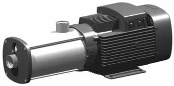
6 2 Product introduction 2. Product introduction Introduction The Grundfos CM and CME pumps are non-self-priming, horizontal, multistage, end-suction centrifugal pumps. The pumps are of the close-coupled. CM pumps are fitted with mains-operated motors whereas the motor for CME pumps has an integrated variable frequency drive. Both CM and CME pumps have mechanical shaft seals. The CM and CME pumps are available in these three material versions: Cast iron (ASTM A48 CL3 / EN-GJL-)* Stainless steel (AISI 34 / EN 1.431) Stainless steel (AISI 316 / EN 1.41). * The impeller, chamber and filling plugs are made of stainless steel (AISI 34 / EN 1.431). The pump shaft is made of stainless steel (AISI 431 / EN 1.57). CM Stainless-steel version Fig. 1 Grundfos CM pumps Cast-iron version The CM pumps are unique products that have been developed in order to fulfill a wide variety of customer demands. The development of the pumps has resulted in no less than five patent applications. TM TM The CM pumps are available in various sizes and numbers of stages to provide the flow and pressure required. The CM pumps consist of two main components: the motor and the pump unit. The motor is a Grundfos motor. The pump unit incorporates optimized hydraulics and offers various s of connections. The pumps offer many advantages; see also Features and benefits on page 1: compact design worldwide usage high reliability service-friendly wide performance range low noise customized solutions. 6

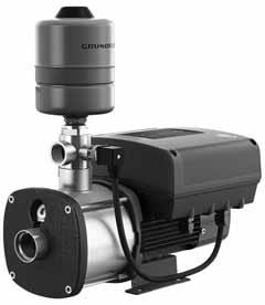
7 2 CME Stainless-steel version Cast-iron version TM TM H Constant curve Fig. 3 Q E-pumps without sensor The pump materials are identical to those of the CM pump range. An E-pump is not just a pump, but a system which is able to solve application problems or save energy in a variety of pump installations. TM Product introduction Fig. 2 Grundfos CME pumps The CME pumps are built on the basis of CM pumps. CME pumps belong to the so-called E-pump family. The difference between the CM and the CME pump ranges is the motor. The CME pump motor is a Grundfos MLE motor. The motor incorporates a variable frequency drive (VFD). Frequency control enables continuously variable control of the motor speed, which makes it possible to set the pump to operation at any duty point. The aim of continuously variable control of the motor speed is to adjust the performance to a given requirement. It is possible to connect a sensor to the built-in variable frequency drive on CME pumps. For further information about CME pumps, see Communication with CME pumps on page 26. The pump materials are identical to those of the CM pump range. CME pumps are used when uncontrolled operation (open loop) is required or when there is a wish to fit a sensor at a later stage in order to enable: Pressure control flow control level control of liquid in a tank temperature control differential pressure control differential temperature control. E-pumps without sensor are also used when a remote analog signal is connected to the setpoint input terminal. 7
8 2 Product introduction New generation CME 3/4 to 3 Hp Permanent magnet motor (Supply voltages T, U) The CME pumps in this range are fitted with the new-generation MLE motors which are permanent-magnet motors incorporating a high-efficiency variable frequency drive. This ensures an even higher efficiency of the pump. The new motor including variable frequency drive has a total efficiency which exceeds the premium efficiency level defined for fixed-speed motors. Standard functional module (FM ) The module has a number of inputs and outputs. The FM has these connections: one analog input two configurable digital inputs two signal relay outputs GENIbus connection. Connection terminals Functional module has been selected as standard for CME pumps. See fig. 4. Terminal Type Function NC C1 NO Normally closed contact Common Normally open contact Signal relay 1 (LIVE or SELV) NC C1 NO NC C2 NO Normally closed contact Common Normally open contact Signal relay 2 (SELV only) +24 V* +24 V* OC DI +24 V* GND +24 V* +24 V* +24 V*/5 V* V*/5 V* + * If an external supply source is used, there must be a connection to GND. Fig. 4 Connection terminals, CME pump + +5 V* NC C2 NO A Y B DI3/OC1 AI1 DI1 +5 V GND GENIbus A GENIbus Y GENIbus B GND +24 V +24 V +5 V GND GDS TX GDS RX AI2 TM DI3/OC1 Digital input/output, configurable. Open collector: Max. 24 V resistive or inductive. 4 AI1 Analog input: - ma / 4- ma V / -5 V / -1 V 2 DI1 Digital input, configurable 5 +5 V Supply to potentiometer and sensor 6 GND Ground A GENIbus, A GENIbus, A (+) Y GENIbus, Y GENIbus, GND B GENIbus, B GENIbus, B (-) 3 GND Ground V Supply V Supply V Supply to potentiometer and sensor 23 GND Ground 25 GDS TX Grundfos Digital Sensor output 24 GDS RX Grundfos Digital Sensor input 7 AI2 Analog input: - ma / 4- ma V / -5 V / -1 V 8
9 2 CME 3/4 to 7.5 Hp Asynchronous motor (Supply voltages M, N, Q) The CME pumps in this range are fitted with the former generation of MLE motors which are asynchronous motors. These motors are energy efficient as standard. The standard I/O module has these connections: start/stop terminals one digital input one setpoint input one sensor input GENIbus connection. Product introduction NC C NO Group 2 L1 L2 L3 Group 3-1 V /4- ma 4- ma 1/ B Y A 1: Digital input 9: GND (frame) 8: +24 V 7: Sensor input B: RS-485B Y: Screen A: RS-485A STOP RUN /4- ma -1 V 1K : GND (frame) 5: +1 V 4: Setpoint input 3: GND (frame) 2: Start/stop TM Fig. 5 Connection terminals 9


10 2 Product introduction Selecting a CME pump Select a CME pump if the following features are required: Controlled operation, i.e. consumption fluctuates constant pressure, flow, or temperature communication with the pump. Adaptation of performance through frequencycontrolled speed offers obvious benefits such as: Energy savings increased comfort control and monitoring of the application and pump performance. For further information about CME pumps, see Communication with CME pumps on page 26. CME Plus CME Plus pumps are built on the basis of CME pumps. In addition to the features of a standard CME, the CME Plus includes a pressure sensor, expansion tank, and discharge piping making it a complete package ready for constant pressure applications. The CME Plus incorporates a stop function ensuring that the pump automatically stops if the water demand drops to a very low level or disappears altogether. The method gives good total operating economy irrespective of the water demand, and the pump is not subjected to overheating and the subsequent risk of damage to the shaft seal. Features and benefits TM TM Modular construction/customized solutions The modular construction of the CM and CME pumps makes it easy to create many different variants based on standard factory parts. This means that it is possible to create pump variants that are customized for the application in question. Worldwide usage With different voltage and frequency combinations, the CM and CME product ranges cover markets worldwide. Various certificates covering worldwide usage are available. Contact Grundfos for details. High reliability New state-of-the-art shaft seal design and materials offering these benefits: high wear resistance and long operating life improved sticking and dry-running capabilities. The pumps are less sensitive to impurities in the pumped liquid than similar pumps of the canned-rotor. Easy installation and service friendly An installation indicator is fitted on three-phase pumps, which makes it easy to see if the electrical connection of the motor is correct. Based on the motor cooling air, it indicates the direction of rotation of the motor. No special service tools required. Kits in stock for quick delivery. All parts available as kits, single parts or in bulk. Service instructions and video make it simple to disassemble and assemble the pump. Service kit instructions available where deemed necessary. Fig. 6 CM and CME pumps CM and CME pumps present the following features and benefits: Compact design and motor are integrated in a compact and user-friendly design. The pump is fitted to a low-profile base plate, making it ideal for installation in systems where a compact pump is required. Fig. 7 Indicator for motor rotation shows black if rotation is correct; white if rotation is incorrect TM
11 2 Wide performance range Can be used in a wide range of applications: washing and cleaning water treatment temperature control pressure boosting chemical industry pharmaceutical industry etc. Product range in WinCAPS and WebCAPS. See section 21. Further product information on page 114. Product introduction Low noise level The CM and CME pumps offer very quiet operation. High-performance hydraulics efficiency is maximized by the optimized hydraulics and carefully crafted production technology. Electrocoated cast-iron parts Optimized corrosion resistance Better efficiency because of smooth surfaces. Customized solutions It is possible to create many different variants of the CM and CME pumps. For further information, see section 17. Customization on page 9. Motor adaptation body modifications. Motors Grundfos motors are remarkably quiet and highly efficient. Grundfos motors are available with integrated variable frequency drive designed for speed-controlled operation. 11
12 3 Performance range 3. Performance range CM, 348 rpm H [m] 1 1 H [ft] 35 CM 348 rpm ISO 996 Annex A CM 1 CM 3 CM 5 CM 1 CM 15 CM Q [US GPM] Q [m³/h] TM CM-A CM-I/G New-generation CME, 6 Hz (Supply voltages T, U) H [m] 1 H [ft] CME 348 rpm 36 6 Hz 1 3 ISO 996 Annex A CME 1 CME 3 CME 5 CME 1 CME Q [US GPM] Q [m³/h] TM CM-A CM-I/G Note: Irrespective of the input frequency, the 1 % speed of CME pumps is approximately 3 rpm. 12
13 3 CME, 348 rpm (Supply voltages M, N, Q) H [m] 1 1 H [ft] 35 CME 348 rpm ISO 996 Annex A Performance range CM 1 CM 3 CM 5 CM 1 CM 15 CM Q [US GPM] Q [m³/h] TM CME-A CME-I/G Note: Irrespective of the input frequency, the 1 % speed of CME pumps is approximately 3 rpm. 13
14 4 Product range 4. Product range 6 Hz Material Shaft seal CM power supply to motor 6 Hz 5/6 Hz Voltage [V] Voltage [V] CME power supply to motor Voltage [V] Cast iron EN-GJL- (CM-A) Stainless steel EN 1.431/AISI 34 (CM-I) Stainless steel EN 1.41/AISI 316 (CM-G) AVBE AVBV AQQE, AQBE AQQV, AQBV AQQK 1 x 115/23 V (supply voltage B) 3 x 8-23/4-48 V (supply voltage E) 3 x 575 V (supply voltage H) 4) 3 x 2-2/ V, (5 Hz)/ 3 x 2-255/38-4 V, (6 Hz) (supply voltage O) 3 x V, (5 Hz)/ 3 x 4-48 V, (6 Hz) (supply voltage J) 3 x V (6 Hz) (supply voltage N) 1 x 8-23 V (6 Hz) (supply voltage M) (To be phased out in 14) 3 x 8-23 V (6 Hz) (supply voltage Q) 3 x 4-48 V (6 Hz) (supply voltage T) 2) 1 x -2 V (6 Hz) (supply voltage U) 2) CM CM CM CM CM CM CM ) CM ) - - CM CM CM CM CM CM CM ) CM ) CM CM CM CM CM CM CM ) CM CM CM CM CM ) CM CM CM CM CM ) Suitable for 6 Hz mains-operated pumps, for CME pumps running at 1 % speed. 2) The new-generation MLE, currently 3/4 to 3 Hp 14
15 5 5. Identification Type key Example CM 1-3 A - R - I - E - A V B E F - A - A - N Type range Sensor variable frequency drive CM: Centrifugal Modular CME: Centrifugal Modular with integrated N: No sensor Rated flow rate Mains plug Rated flow rate [m 3 /h] A: Prepared for cable glands B: Harting plug Number of impellers C: With cable D: Cable gland included Identification version Motor information A: Basic version A: Standard motor (IP55) B: Oversize motor (one flange size larger) B: Phase-insulated motor for use with variable frequency drive E: s with certificates/approvals C: Condensing environments N: CME pump with pressure sensor D: Pt1 in stator P: Undersize motor (one flange size smaller) E: Angular contact bearing T: Oversize motor (two flange sizes larger) F: Motor heater BE: Oversize motor with certificates/approvals G: Three-phase motor with overload protection BN: Oversize motor with pressure sensor H: Single-phase motor with no protection EN: s with certificates/approvals and pressure sensor I: Radio communication not available EP: s with certificates/approvals and undersize motor ET: s with certificates/approvals and double-oversize motor Supply voltage EX: s with certificates/approvals and two other variants selected A: 1 x 2 V, 6 Hz NP: Undersize motor with pressure sensor B: 1 x 115/23 V, 6 Hz NT: Double-oversize motor with pressure sensor B1: 1 x 115/23 V, 6 Hz, with terminal board X: Special pump C: 1 x 2-2 V, 5 Hz D: 1 x 127 V, 6 Hz Pipe connection E: 3 x 8-23/4-48 V, 6 Hz C: Tri-Clamp E1: 3 x 8-23/4-48 V, 6 Hz, with terminal board F: DIN/ANSI/JIS flange F: 3 x 2-2/ V, 5 Hz P: Victaulic coupling G: 3 x /346 V, 5 Hz; -2/ V, 6 Hz R: Whitworth thread Rp (ISO 7/1) H: 3 x 575 V, 6 Hz S: Internal NPT thread I: 3 x V, 5/6 Hz J: 3 x V, 5 Hz; 4-48 V, 6 Hz Materials in contact with pump media K: 1 x -2 V, 5/6 Hz (E-motor) A: Suction and discharge parts EN-GJL- L: 3 x V, 5/6 Hz (E-motor) shaft AISI 34 / EN M: 1 x 8-23 V, 6 Hz (E-motor) Impellers/chambers AISI 34 / EN N: 3 x V, 6 Hz (E-motor) G: Sleeve AISI 316 / EN 1.41 O: 3 x 2-2/ V, 5 Hz 3 x 2-255/38-4 V, 6 Hz shaft AISI 316 / EN 1.41 Q: 3 x 8-23 V, 6 Hz (E-motor) Impellers/chambers AISI 316 / EN 1.41 R: 3 x -23 V, 5/6 Hz (E-motor) I: Sleeve AISI 34 / EN S: 3 x 38-5 V, 5/6 Hz (E-motor) 1) shaft AISI 34 / EN T: 3 x 4-48 V, 6 Hz (E-motor) 1) Impellers/chambers AISI 34 / EN U: 1 x -2 V, 6 Hz (E-motor) 1) X: Special version Rubber parts in pump (excluding neck ring and shaft seal) Material of secondary seal E: EPDM (ethylene propylene) E: EPDM (ethylene propylene) K: FFKM (perflour) K: FFKM (perflour) V: FKM (flour) V: FKM (flour) Note: Gaskets between chambers of cast-iron versions are always made of Tesnit BA-U. Material of stationary seal face B: Carbon, resin-impregnated Q: Silicon carbide (SIC) Shaft seal U: Tungsten carbide A: O-ring seal with fixed driver R: O-ring seal with fixed driver and reduced seal face Material of rotating seal face Q: Silicon carbide (SIC) V: Aluminium oxide (AI3) U: Tungsten carbide Note: The key cannot be used for ordering as not all combinations are possible. 1) The new-generation MLE, currently 3/4 to 3 Hp. * Standard offering in U.S. ** Standard voltage in Canada. Approvals CM CME 15

16 6 Construction 6. Construction The CM and CME pumps are non-self-priming, horizontal, multistage centrifugal pumps. The pumps have an axial suction port and a radial discharge port and are mounted on a base plate. All movable parts are made of stainless steel. The pumps are available with mains-operated motors (CM pumps) and with variable frequency drive motors (CME pumps). All pumps incorporate a maintenance-free mechanical O-ring shaft seal with fixed driver. Motor CM and CME pumps are fitted with totally enclosed, fan-cooled, 2-pole motors. CM pumps up to and including 2 Hp are available with single-phase motors as standard. CME pumps up to and including 1.5 Hp are available with single-phase motors as standard. CM and CME pumps from 2 to 1 Hp are fitted with three-phase motors. Efficiency All three phase motors of 1 Hp and up are energy efficient as standard. Premium efficient motors are available on request. The new-generation MLE motors have a total efficiency which exceeds the premium efficient level defined for fixed-speed motors including the variable frequency drive. Fig. 8 Cast-iron versions Stainless-steel versions CM and CME pumps TM TM TM TM Approvals Approvals Electrical data Insulation class Enclosure class Efficiency Supply voltages (tolerance ± 1 %) CM F TEFC (IP55)* Energy Efficient (IE2)** CME CM 1 x 115/23 V, 6 Hz (B) 3 x 8-23/4-48 V, 6 Hz (E) 3 x 575 V, 6 Hz (H) 3 x V, 5 Hz; 3 x 4-48 V, 6 Hz (J) CME 1 x -2 V, 6 Hz (U) 3 x 8-23 V, 6 Hz (M) 3 x V, 6 Hz (N) 3 x 4-48 V, 6 Hz (T) * IP55 is not recommended for operation in condensing environments. For operation in such environments, see Operation in condensing environments on page 24. **Premium efficient (IE3) available on request TM Fig. 9 CM and CME pump hydraulics 16
17 6 Motor protection CM Single-phase motors, 1 x 115/23 V, 6 Hz, do not incorporate motor protection and must be connected to a motor-protective circuit breaker which can be manually reset. Set the motor-protective circuit breaker according to the rated current of the motor (I 1/1 ). See nameplate. Other single-phase motors have built-in current- and temperature-dependent motor protection in accordance with IEC and require no further motor protection. The motor protection is of the T11, which reacts to both slow- and quick-rising temperatures. The motor protection is automatically reset. Three-phase motors up to 5 Hp must be connected to a motor-protective circuit breaker which can be manually reset. Set the motor-protective circuit breaker according to the rated current of the motor (I 1/1 ). See nameplate. Electronically speed-controlled motors (CME) CME pumps require no external motor protection. The MLE motor incorporates thermal protection against slow overloading and stalled condition (IEC 34-11). Variable frequency drive (VFD) operation All three-phase motors can be connected to a variable frequency drive. Depending on the of variable frequency drive, this may cause increased acoustic noise from the motor. Furthermore, it may cause the motor to be exposed to detrimental voltage peaks. As standard ML 9 motors and above include phase insulation. As standard ML 71- and ML 8-based motors have no phase insulation and must therefore be protected against voltage peaks higher than 65 V (peak value) between the supply terminals. Note: ML 71- and ML 8-based motors with phase insulation are available on request. The above disturbances, i.e. both increased acoustic noise and detrimental voltage peaks, can be eliminated by fitting an LC filter between the variable frequency drive and the motor. For further information, please contact the variable frequency drive supplier or Grundfos. Shaft seal The shaft seal for the CM and CME pumps is of the O-ring, which makes it very flexible when different s of O-rings and seal-face materials are needed. The shaft seal has a fixed seal driver which ensures a reliable rotation of all parts even under the most extreme operating conditions. Due to the special design of the shaft seal and the interfaces to the rest of the pump construction, the dry-running capabilities are improved significantly compared to most other similar shaft seals and pump s. Furthermore, improvements have been made to reduce the risk and effect of sticking. The shaft seal s available can be found in Selection of shaft seal on page 36 where the key parameters of selecting a shaft seal are also described. Fig. 1 Exploded view of shaft seal Note: The available shaft seals for CM and CME pumps are very robust and durable, but dry running must always be avoided. Details regarding operating conditions for the shaft seal can be found in Operating range of the shaft seal on page 24. Further information about the shaft seal can be found in separate documentation covering shaft seals which can be downloaded from WebCAPS. See 21. Further product information on page 114. Title Publication number Shaft seals TM Construction 17
18 6 Construction Sectional drawings CM(E) A (A = cast iron, A48 CL3 / EN-GJL-) TM Fig. 11 CM(E) 1-3 with ML(E) 71 motor Components Pos. Component Pos. Component Pos. Component 2 Discharge part 64c Clamp 153 Ball bearing 4 Chamber 66 Washer (NORD-LOCK ) 155 Bearing cover plate 6 Inlet part 67 Nut 156 Fan 11 O-ring 79 Diverting disc 158 Corrugated spring 25 Plug 15 Shaft seal 158a O-ring 49 Impeller 139b Gasket 159 O-ring 51 shaft 15 Stator housing 164b, 164e Terminal box 64 Spacing pipe 151 Fan cover 191 Base plate 18
19 6 CM(E) I and CM(E) G (I = AISI 34 / EN and G = AISI 316 / EN 1.41) Construction TM Fig. 12 CM(E) 1-3 with ML(E) 71 motor Components Pos. Component Pos. Component Pos. Component 4 Chamber 64c Clamp 155 Bearing cover plate 6 Flange 66 Washer (NORD-LOCK ) 156 Fan 16 Sleeve 67 Nut 157a Gasket 25 Plug 79 Diverting disc 158 Corrugated spring 31 O-ring 15 Shaft seal 158a O-ring 49 Impeller 15 Stator housing 159 O-ring 51 shaft 151 Fan cover 164b, 164e Terminal box 64 Spacing pipe 153 Ball bearing 191 Base plate 19
20 6 Construction Material specification Pos. Description Material Motor parts 156b Motor flange Cast iron 15 Stator housing Silumin (Alu) 151 Fan cover Composite PBT/PC 153 Ball bearing 156 Fan Composite PA 66 3 % GF 158 Corrugated spring Steel 164b Terminal box, MG Composite PC/ASA or 164e Terminal box, MGE silumin (Alu) 191 Base plate Steel, electro-coated Steel, powder-coated, 6 to 1 µ, NCS Diverting disc Silicone fluid (LSR) 155 Bearing cover plate PPS parts 15 Shaft seal, steel parts Shaft seal, seal faces Stainless steel SiC/SiC or Al 2 O 3 /carbon CM(E) A Cast iron (ASTM A48 CL3/ EN-GJL-) material version CM(E) I Stainless steel (AISI 34 / EN 1.431) CM(E) G Stainless steel (AISI 316) / EN 1.41 DIN W.-Nr. ISO/AISI/ASTM DIN W.-Nr. ISO/AISI/ASTM DIN W.-Nr. ISO/AISI/ASTM ASTM A366 / A611-C1 51 shaft Stainless steel AISI ) 158a 159 O-rings EPDM, FKM or FFKM 157a 1) Gasket Paper 139b 2) Gasket Aramide fibers (nbr) 2 2) Discharge part Cast iron 6 2) Inlet part Cast iron ASTM A366 / A611-C ASTM A366 / A611-C / AISI 34/ 1.431/ AISI 34/ 1.41 *) AISI 316 *) 1.41 *) AISI 316 *) 1.41 AISI / 1.41 *) AISI 34/ AISI 316 *) 1.41 AISI / AISI 34/ 1.431/ AISI 34/ 4 Chamber Stainless steel 1.41 *) AISI 316 *) 1.41 *) AISI 316 *) 1.41 AISI Plug Stainless steel 1.44 AISI 316L 1.44 AISI 316L 1.44 AISI 316L 49 Impeller Stainless steel 1.431/ AISI 34/ 1.431/ AISI 34/ 1.41 *) AISI 316 *) 1.41 *) AISI 316 *) 1.41 AISI Spacing pipe Stainless steel 1.41 AISI AISI AISI c Clamp Stainless steel STX 3) STX 3) STX 3) 6 1) Flange Cast iron 16 Sleeve Stainless steel 67 Nut Stainless steel A4 66 Washer (NORD-LOCK ) 1.431/ 1.41 *) AISI 34/ AISI 316 *) 1.41 AISI 316 Steel ) ) ) *) On request. 1) Only in CM(E)-I/G pumps. 2) Only in CM(E)-A pumps. 3) STX ~ CrNiMO ) ~ CrNiMoCuN
21 7 7. Operating conditions Ambient temperature The maximum ambient temperature depends on the liquid temperature. The table below shows within which temperature ranges the CM and CME pumps should be used. Note: The maximum permissible liquid temperature for CM-A and CME-A is +194 F (+9 C). Maximum ambient temperature [ F ( C)] Liquid temperature CM CME 1) CME 2) +131 (+55) +194 (+9) (+5) +212 (+1) - Storage and transport temperature CM: +58 to +158 F ( 5 to +7 C). CME: 22 to +1 F ( 3 to +6 C). Installation altitude Installation altitude is the height above sea level of the installation site. Motors installed at maximum altitude can be loaded 1 %. Motors installed above maximum altitude must not be fully loaded due to the low density and consequently low cooling effect of the air. Operating conditions +113 (+45) +23 (+11) (+) +248 (+1) 1) New-generation CME supply voltages T, U. 2) New-generation CME supply voltages M, N, Q. CM If the ambient temperature for CM pumps exceeds +131 F (+55 C) the motor must not be fully loaded due to the risk of overheating. In such cases, it may be necessary to derate the motor output or use an oversize motor with higher rated output. The CM pumps can be derated in relation to ambient temperature without consequence. Contact Grundfos for further information. P2 [%] 1 CM [%] [ft] [m] Fig. 14 Relationship between motor output ( ) and altitude 3 1 TM t [ C] Fig. 13 Derating of CM pump, in relation to ambient temperature t [ F] CME (variable frequency drive motors) The electronics incorporated in the CME pumps is limiting the maximum ambient temperature. This means that the maximum ambient temperature must not be exceeded. If the pump is operated at temperatures exceeding the maximum ambient temperature, the motor life will be reduced. Maximum ambient temperature CME 3/4 to 3 Hp (supply voltages T, U): +122 F (+5 C). CME 3/4 to 7.5 Hp (supply voltages M, N, Q): +14 F (+ C.) TM Pos. Motor output CM CME 1) CME 1) New-generation CME supply voltages T, U. 21
22 7 Operating conditions Temperatures and pressures Maximum operating pressure and permissible liquid temperature The maximum operating pressure and the permissible liquid temperature depend on the pump material, the of shaft seal and the pumped liquid. Material variant Cast iron (A48 CL3 / EN-GJL-) Shaft seal AVBx Permissible liquid temperature 1) [F ( C)] Maximum operating pressure [psi (bar)] 4 to +14 ( to +) 145 (1) +15 to +194 (+41 to +9) 87 (6) AQQx 4 to +194 ( to +9) 145 (1) Maximum liquid temperature change gradient Cast-iron pumps (CM-A, CME-A) should not be used in applications where rapid temperature changes of more than +81 F (+45 C) may occur. If exposed to such rapid temperature changes, a cast-iron pump may leak. Under such operating conditions, we recommend to use stainless-steel pumps (CM-I, -G and CME-I, -G). Liquid temperature range O-ring material / liquid Permissible liquid temperature [ F ( C)] EPDM 4 to +248 ( to +1) FFKM +32 to +248 ( to +1) FKM / liquids containing water 4 to +194 ( to +9) Stainless steel (AISI 34 / EN 1.431) AVBx AQQx +4 to +14 ( to +) 145 (1) +15 to +194 (+41 to +9) 87 (6) 4 to +194 ( to +9) 3) 232 (16) +195 to +248 (+91 to +1) 2) 145 (1) FKM / oil without water 4 to +248 ( to +1) Stainless steel (AISI 316 / EN 1.41) AVBx AQQx 4 to +14 ( to +) 145 (1) +15 to +194 (+41 to +9) 87 (6) 4 to +194 ( to +9) 3) 232 (16) +195 to +248 (+91 to +1) 2) 145 (1) 1) At liquid temperatures below +32 F ( C), higher motor outputs may be needed due to increased viscosity, for instance if glycol has been added to the water. 2) +248 F (+1 C) applies only if the pump has an AQQE shaft seal. 3) CM-I, -G and CME-I, -G pumps for liquid temperatures below 4 F ( C) are available on request. Please contact Grundfos. 22
23 7 Maximum inlet pressure The maximum inlet pressure of the CM pumps is equal to the maximum operating pressure of the pump minus the pumps discharge pressure against a closed valve. For example: CM5-3 A-S-A-E-AQQE Max. operating pressure: 145 psi Discharge pressure against closed valve: 57 psi Max. inlet pressure=145-57=88 psi Minimum inlet pressure NPSH Calculation of the inlet pressure "H" is recommended in these situations: The liquid temperature is high. The flow is significantly higher than the rated flow. Water is drawn from depths. Water is drawn through long pipes. Inlet conditions are poor. To avoid cavitation, make sure that there is a minimum pressure on the suction side of the pump. The maximum suction lift "H" in feet of head can be calculated as follows: H H f p b NPSH H V Fig. 15 Minimum inlet pressure (NPSH) Note: To avoid cavitation, never select a pump with a duty point too far to the right on the NPSH curve. Always check the NPSH value of the pump at the highest possible flow. Sound pressure The sound pressure values in the table below apply for CM pumps. If the motor output ( ) for a given CM pump is not found in the table, use the nearest rounded-up value. The values for sound pressure include a tolerance of 3 db[a] according to EN ISO Hz 5 Hz TM Operating conditions H = p b NPSH H f H v H s p b = Barometric pressure in feet absolute. (Barometric pressure can be set to 33.9). In closed systems, p b indicates the system pressure in feet. NPSH = Net Positive Suction Head in feet of head. (To be read from the NPSH curve at the highest flow the pump will be delivering). H f = Friction loss in suction pipe in feet of head. (At the highest flow the pump will be delivering). H v = Vapor pressure in feet of head. (To be read from the vapor pressure scale. "H v " depends on the liquid temperature "T m "). H s = Safety margin = minimum 2 ft of head. If the "H" calculated is positive, the pump can operate at a suction lift of maximum "H" feet of head. If the "H" calculated is negative, an inlet pressure of minimum "H" feet of head is required. [Hp (kw)] L pa [db(a)] L pa [db(a)].5 (.37) (.55) (.75) (1.1) (1.5) (2.2) (3.) (4.) (5.5) (7.5) 65 6 The audible noise from CM pumps is primarily noise from the motor fan. The selection of CME pumps will reduce the noise at partial load, as the motor, and consequently, the motor fan runs at a lower speed. Possible flow noise from control valves is also reduced at partial load in the case of the CME pump. Sound pressure values are measured at 3 ft. 23
24 7 Operating conditions Operation in condensing environments If the liquid temperature becomes lower than the ambient temperature, condensation may form in the motor during inactivity. In such cases a motor suited for condensing environments must be used. When installing CM and CME pumps outdoors, provide them with a suitable cover to protect them from build-up of water condensation. See fig. 16. Operating range of the shaft seal The operating range of the shaft seal depends on operating pressure, of shaft seal and liquid temperature. The curve in fig. 17 shows which shaft seals are suitable at a given temperature and a given pressure. The curve applies to clean water. Fig. 16 CME pump with protective cover Motors in outdoor installations radiate heat to and absorb heat from their surroundings. By day, a stopped motor will absorb more heat than it radiates; by night, especially clear nights, radiation from a stopped motor may be so high that the surface temperature falls a few degrees below the air temperature. This may cause the formation of condensation. Condensation on the inner surfaces may result in moisture on the electronic components, including the printed-circuit boards, which means a risk of failure or even destruction of the motor and electronics. Furthermore, the cover protects the motor against direct sunlight. Environmental rating Three-phase ML/MLE motors hold a UL NEMA 3R environmental rating. Single-phase MGE/MLE motors have not been tested against the UL NEMA environmental rating. All motors are IP55. When the rubber plug is removed the rating becomes IP34. This applies to both CM and CME pumps. The use of a cover does not affect the IP rating. TM ** AQQE AQQV AVBE AVBV AQQE AQQV AVBE AVBV AQQE AQQV AQQK AQQE AQQV AQQK AVBE AVBV AQQE * -* Fig. 17 Selection of shaft seals AQQV AQQK AQQE AQQV*** AQQK t [F ] t [C ] * Antifreeze should be added at liquid temperatures below +32 F ( C). ** CM and CME pumps for liquid temperatures below 4 F ( C) are available on request. Please contact Grundfos. *** AQQV above 194 F (+9 C) only in media not containing water. Viscosity The pumping of liquids with densities or kinematic viscosities higher than those of water will cause a considerable pressure drop, a drop in the hydraulic performance and a rise in the power consumption. For instance at liquid temperatures below +32 F ( C), higher motor outputs may be needed due to increased viscosity if glycol has been added to the water. In such situations, the pump should be fitted with a larger motor. If in doubt, contact Grundfos or visit WebCAPS. See page 114. TM
25 7 Installation of pump The pump must be installed on a plane surface and fixed so that it cannot be displaced during start-up and operation. The pump must be installed so that air locks are avoided in the pump housing and pipework; fig. 18 shows the permissible pump positions. Operating conditions Up Floor TM Fig. 18 Permissible pump positions The pump should be installed with easy access for inspection, maintenance and service. The pump should be installed in a well-ventilated location. Frequency of starts and stops Maximum of 1 per hour. 25
26 8 CME pumps 8. CME pumps Communication with CME pumps Communication with CME pumps is possible by means of: control panel on the pump Grundfos GO remote Grundfos R1 remote control a central building management system. Grundfos GO Remote CME pumps can communicate with the Grundfos GO Remote via radio or infrared light. The Grundfos GO Remote enables setting of functions and gives access to status overviews, technical product information and actual operating parameters. The Grundfos GO Remote offers three different mobile interfaces (MI). See fig.. Control panel The operator can change the setpoint settings manually on the control panel of the CME pump terminal box. The design and functionality of the control panels vary, depending on the MLE motor fitted to the CME pump. The control panel of the new-generation CME pumps enables radio communication. The Grundfos Eye at the top of the control panel is a pump status indicator light providing information about the pump operating status. Less or more advanced control panels are available on request. New-generation CME with supply voltages T, U Stop Fig. 19 Standard control panels of CME pumps TM CME with supply voltages M, N, Q TM 76 4 Fig. Grundfos GO Remote Pos Description Grundfos MI 1: Consists of an Apple ipod touch 4G and a Grundfos cover. Grundfos MI 2: Add-on module which can be used in conjunction with Apple ipod touch 4, iphone 4G or later. Grundfos MI 4: Add-on module which can be used in conjunction with Apple ipod touch 5G or iphone 5. The Grundfos GO Remote is available as an accessory. See page Grundfos MI 31: Separate module enabling radio or infrared communication. The module can be used in conjunction with an Android or ios-based Smartphone with Bluetooth connection TM

27 8 R1 remote control The operator communicates with the CME pump by pointing the R1 at the control panel of the CME terminal box. TM CME pumps Fig. 21 R1 remote control With the R1 it is possible to monitor and change control modes and settings of the CME. Central building management system The operator can communicate with a CME pump at a distance. Communication can take place via a central building management system allowing the operator to monitor and change control modes and setpoint settings. The communication interface between the CME pump and central building management systems varies, depending on pump size. New-generation CME 3/4 to 3 Hp (supply voltages T, U) This range of CME pumps can be fitted with a communication interface module (CIM). This means that no external communication interface is required. CME 3/4 to 7.5 Hp (supply voltages M, N, Q) This range of CME pumps communicates via an external communication interface unit (CIU). Supply voltages: T, U CIU 1: LonWorks CIU 15: PROFIBUS DP CIU : Modbus RTU CIU 25: GSM CIU 27: GRM CIU 3: BACnet MS/TP CIM 1: LonWorks CIM 15: PROFIBUS DP CIM : Modbus RTU CIM 25: GSM/GPRS CIM 27: GRM CIM 3: BACnet MS/TP Supply voltages: M, N, Q Fig. 22 Communication via a central building management system TM
28 8 CME pumps Speed control of CME pumps Affinity equations Normally, CME pumps are used in applications characterized by a variable flow. Consequently, it is not possible to select a pump that is constantly operating at its optimum efficiency. In order to achieve optimum operating economy, the duty point should be close to the optimum efficiency (eta) for most operating hours. Between the min. and max. performance curves, CME pumps have an infinite number of performance curves, each representing a specific speed. It may therefore not be possible to select a duty point close to the max. curve. H H n H x Eta Q x n n n x Q n n x n n Q Q n n n Q x n x H n n n H x n x n x H [m] [ft] Max. curve P n P Q x Q n n n Q P n n n P n x x Min. curve Q [m³/h] [gpm] TM P x n x Fig. 24 Affinity equations Legend Q TM Fig. 23 Min. and max. performance curves In situations where it is not possible to select a duty point close to the max. curve, use the affinity equations below. The head (H), the flow rate (Q) and the input power (P) are the appropriate variables for calculating the motor speed (n). Note: The approximated formulas apply on condition that the system characteristic remains unchanged for n n and n x and that it is based on the formula H = k x Q 2 where k is a constant. The power equation implies that the pump efficiency is unchanged at the two speeds. In practice, this is not quite correct. Finally, it is worth noting that the efficiency of the variable frequency drive and the motor must be taken into account if a precise calculation of the power saving resulting from a reduction of the pump speed is wanted. H n H x Q n Q x n n n x n x Rated head Current head Rated flow rate Current flow rate Rated motor speed Current motor speed Rated efficiency Current efficiency WinCAPS and WebCAPS WinCAPS and WebCAPS are selection programs offered by Grundfos. The two programs make it possible to calculate the specific duty point and energy consumption of a CME pump. When you enter the dimensions of the pump, WinCAPS and WebCAPS can calculate the exact duty point and energy consumption. For further information, see page


29 8 CM connected to Grundfos CUE external variable frequency drive Functions Intuitive start-up guide The start-up guide enables easy installation and commissioning as well as plug-and-pump convenience. Few settings need to be made by the installer as the rest is done automatically or preset from the factory. CME pumps Smart user interface GrA 44 TM Fig. 25 Grundfos CUE product range Grundfos CUE is a complete range of external variable frequency drives (VFDs) for pump control in a wide range of applications. Grundfos CUE is designed for wall mounting. Grundfos CUE provides a variety of benefits to the end-user. The benefits include: Grundfos CME pump functionality and user interface application and pump family-related functions increased comfort compared to mains-operated pump solutions simple installation and commissioning compared to standard VFDs. Fig. 26 Grundfos CUE control panel Grundfos CUE features a unique user-friendly control panel with graphic display and easy-to-use buttons. Panel layout resembles the well-known Grundfos R1 remote control, which is used with Grundfos CME pumps. Controlling the value you choose Grundfos CUE has a built-in PI controller offering closed-loop control of a desired value. The values include: constant differential-pressure proportional pressure constant temperature constant flow. Wide product range The CUE product range is quite comprehensive, covering five different voltage ranges, enclosure classes IP/21 (Nema 1) and IP54/55 (Nema 12), and a wide range of output powers. The table below provides a general overview. Input voltage [V] Output voltage [V] Motor 1 x -2 3 x x -2 3 x x x x x
30 9 Approvals and markings 9. Approvals and markings Approvals C-tick mark, New Zealand and Australian EMC. TR certificate. culus The culus approval covers the following supply voltages: 1 x 115/23 V, 6 Hz (supply voltage B) 3 x 8-23/4-48 V, 6 Hz (supply voltage E) 3 x 575 V, 6 Hz (supply voltage H) 1 x 115/23 V, 6 Hz (supply voltage B1) 3 x 8-23/4-48 V, 6 Hz (supply voltage E1) 3 x V, 5/6 Hz (supply voltage I) 3 x V, 5 Hz/3 x 4-48 V, 6 Hz (supply voltage J). s UL778 and C22.2 No 18-1 NEMA 25 (IP code). Overheating protection UL2111 and C22.2 No Note: culus/curus-approved motors have no internal protection. Motors fitted with PTC/PTO have no culus/curus approval. curus motors CME motors comply with UL58C and C22.2 No 14. The curus approval covers the following supply voltages: 3 x V, 5/6 Hz (supply voltage L) 3 x V, 6 Hz (supply voltage N) 1 x 8-23 V, 5/6 Hz (supply voltage M) 3 x 8-23 V, 5/6 Hz (supply voltage Q) 3 x -46 V, 6 Hz (supply voltage G) 1 x V, 6 Hz (supply voltage B) 1 x -2 V, 5/6 Hz (supply voltage K) 3 x 38-5 V, 5/6 Hz (supply voltage S) 3 x 4-48 V, 5/6 Hz (supply voltage T) 1 x -23 V, 5/6 Hz (supply voltage U). Other approvals and compliance with directives GOST (Russia) Compliance with RoHS, directive 2/96/EC CCC CEL EuP. Drinking water approvals WRAS ACS NSF61. Markings 5 C-tick CE culus curus UL TR CCC 3
31 1 1. Certificates Certificate Certificate of compliance with the order Test certificate. Non-specific inspection and testing Inspection certificate 3.1 Inspection certificate Standard test report Material specification report Material specification report with certificate from raw material supplier Duty-point verification report Surface-roughness Vibration report Motor test report Cleaned and dried pump Electro-polished pump Description According to EN 14, 2.1. Grundfos document certifying that the pump supplied is in compliance with the order specifications. According to EN 14, 2.2. Certificate with inspection and test results of a non-specific pump. Grundfos document certifying that the pump supplied is in compliance with the order specifications. Inspection and test results are mentioned in the certificate. Grundfos document certifying that the pump supplied is in compliance with the order specifications. Inspection and test results are mentioned in the certificate. Certificate from the surveyor is included. We offer the following inspection certificates: Lloyds Register of Shipping (LRS) Det Norske Veritas (DNV) Germanischer Lloyd (GL) Bureau Veritas (BV) American Bureau of Shipping (ABS) Registro Italiano Navale Agenture (RINA) China Classification Society (CCS) Russian maritime register of Shipping (RS) Biro Klassifikasio Indonesia (BKI) United States Coast Guard (USCG) Nippon Kaiji Koykai (NKK) Certifies that the main components of the specific pump are manufactured by Grundfos, and that the pump has been QH-tested, inspected and conforms to the full requirements of the appropriate catalogues, drawings and specifications. Certifies the material used for the main components of the specific pump. Certifies the material used for the main components of the specific pump. A material certificate, EN 14, 3.1, will be supplied for each main component. Certifies a test point specified by the customer. Issued according to ISO 996:1999 concerning "Duty point verification". Shows the measured roughness of the cast pump base of the specific pump. The report indicates the values measured at the base inlet and outlet according to ISO 132. Vibration report indicating the values measured during the performance test of the specific pump according to ISO Shows the performance test of the specific motor, including power output, current, temperature, stator windings resistance and insulation test. Confirms that the specific pump has been cleaned and dried, and how it was done. Confirms that the specific pump has been electro-polished. The maximum surface roughness is specified in the report. Certificates Examples of the certificates are shown on page 32. Note: Other certificates are available on request. 31
32 1 Certificates Examples of certificates Certificate of compliance with the order Certificate of compliance with the order EN Test certificate Test certificate Non-specific inspection and testing EN Customer name Customer order no. Customer Tag no. GRUNDFOS order no. Product We the undersigned hereby guarantee and certify that the materials and/or parts for the above mentioned product were manufactured, tested, inspected, and conform to the full requirements of the appropriate catalogues, drawings and/or specifications relative thereto. Customer name Customer order no. Customer TAG no. GRUNDFOS order no. Motor make Flow m 3 /h Head m Power P2 kw Voltage V Frequency Hz Full load current A Motor speed min -1 Part number Part number We the undersigned hereby guarantee and certify that the materials and/or parts for the above mentioned product were manufactured, tested, inspected, and conform to the full requirements of the appropriate catalogues, drawings and / or specifications relative thereto. GRUNDFOS Date: Signature: Name: Dept.: Part no /112 TM GRUNDFOS Date: Signature: Name: Dept.: Part no /112 TM Inspection certificate 3.1 Inspection certificate Inspection certificate. EN Inspection certificate. Russian Maritime Register of Shipping Manufactured by GRUNDFOS order no. GRUNDFOS DUT id. Customer order no. Customer name and address Shipyard / factory Ship / new building Customer TAG no. Classifying society GRUNDFOS authorized department Motor Make Part number Part number Serial no. Serial No. Flow rate (m 3 /h) P2 (kw) Head (m) Voltage (V) Max. ope. P/t (bar / C) Current (A) Din / W. - No. n(min -1 ) Base/ head cover Frequency (Hz) Impeller/guidevanes Insulation class Shaft/sleeve Power factor Customer s requirements Flow rate (m 3 /h) Head (m) Manufactured by GRUNDFOS order no. GRUNDFOS DUT id. Customer order no. Customer name and address Shipyard / factory Ship / new building Customer TAG no. Classifying society Russian Maritime Register of Shipping ( RS ) Motor Make Part number Part number Serial no. Serial No. Flow rate (m 3 /h) P2 (kw) Head (m) Voltage (V) Max. ope. P/t (bar / C) Current (A) Service n(min -1 ) Medium Frequency (Hz) Din / W. - No. Insulation class Base/ head cover Power factor Impeller/guidevanes Shaft/sleeve Test result ref. requirements Q(m 3 /h) H(m) n(min -1 ) I(A) P1(kW) Customer s requirements Flow rate (m 3 /h) Head (m) Hydrostatic test Bar no leaks or deformation observed Test result ref. requirements Q(m 3 /h) H(m) n(min -1 ) I(A) P1(kW) Hydrostatic test Bar no leaks or deformation observed The pump has been marked GRUNDFOS Date: Signature: Name: Dept.: Part no / TM Surveyor signature: Tested date: GRUNDFOS Date: Signature: Name: Dept.: Part no / TM
33 1 Standard test report Standard test report Material specification report Material specification report. Certificates Customer name Customer order no. Customer Tag no. GRUNDFOS order no. Product GRUNDFOS DUT id. Part number We the undersigned hereby guarantee and certify that the materials and/or parts for the above mentioned product were manufactured by GRUNDFOS, tested, inspected, and conform to the full requirements of the appropriate catalogues, drawings and/or specifications relative thereto. The attached test result is from the above mentioned pump. Customer name Customer order no. Customer TAG no. GRUNDFOS order no. GRUNDFOS DUT id. Part number Production code Materials DIN W.-Nr. AISI / ASTM head head cover Shaft Impeller Chamber Outer sleeve Base We the undersigned hereby guarantee and certify that the materials and/or parts for the above mentioned product were manufactured, tested, inspected, and conform to the full requirements of the appropriate catalogues, drawings and/or specifications relative thereto. GRUNDFOS Date: Signature: Name: Dept.: Part no P1 /A72775 TM GRUNDFOS Date: Signature: Name: Dept.: Part no /A72775 TM Material specification report with certificate from raw material supplier Duty-point verification report Material specification report with EN material certificate from raw material supplier Duty point verification report Customer name Customer order no. Customer TAG no. GRUNDFOS order no. GRUNDFOS DUT id. Part number Production code Customer name Customer order no. Customer Tag no. GRUNDFOS order no. Product GRUNDFOS DUT id. Part number We the undersigned hereby guarantee and certify that the materials and/or parts for the above mentioned product were manufactured by GRUNDFOS, tested, inspected, and conform to the full requirements of the appropriate catalogues, drawings and/or specifications relative thereto. Raw materiel no. Supplier certificate no. head head cover Shaft Impeller Chamber Outer sleeve Base We the undersigned hereby guarantee and certify that the materials and/or parts for the above mentioned product were manufactured, tested, inspected, and conform to the full requirements of the appropriate catalogues, drawings and/or specifications relative thereto. GRUNDFOS Date: Signature: Name: Dept.: Part no /A72775 TM GRUNDFOS Date: Signature: Name: Dept.: Part no /A72775 TM
34 11 Selection and sizing 11. Selection and sizing Selection of pumps Selection of pumps should be based on these elements: the duty point of the pump (see fig. 27) dimensional data such as pressure loss as a result of height differences, friction loss in the pipework, pump efficiency, etc. (see fig. 28) pump materials (see 6. Construction on page 16) pump connections (see page 35) shaft seal (see page 36). Duty point of the pump From a duty point it is possible to select a pump on the basis of the curve charts starting on page. Dimensional data When sizing a pump, take the following factors into account: Required flow and pressure at the draw-off point. Pressure loss as a result of height differences (H geo ). Friction loss in the pipework (H f ). It may be necessary to account for pressure loss in connection with long pipes, bends or valves, etc. Best efficiency at the estimated duty point.* NPSH value. For calculation of the NPSH value, see Minimum inlet pressure on page 23. * See Selection of CME pumps on page 36 for further information about sizing CME pumps. H [m] 11 H [ft] CM rpm Required flow and pressure ISO 996 Annex A H f H geo NPSH TM Q [US GPM] Q [m³/h] P2 P2 [kw] [hp] Q [US GPM] NPSH NPSH Eff [m] [ft] [%] 6 Eff NPSH Q [US GPM] Fig. 27 Example of a curve chart TM Fig. 28 Dimensional data efficiency When sizing the pump, the efficiency (eta) should be considered so that the pump will operate at or near its maximum efficiency, for instance on the right-hand side in the curve example in fig. 29. Eff Eta Fig. 29 Best efficiency Q [ m3 Before determining the best efficiency point, the operation pattern of the pump needs to be identified. If the pump is expected to operate at the same duty point, then select a CM pump which is operating at a duty point corresponding with the best efficiency of the pump. The example in fig. 3 shows how to check the pump efficiency when selecting a CM pump. TM
35 11 H [m] H [ft] CM rpm ISO 996 Annex A Duty point connections Tri-Clamp Selection and sizing P2 [kw] NPSH [m] P2 [hp] Fig. 3 Example of a CM pump s duty point materials Select the material variant on the basis of the liquid to be pumped. The table below gives a general recommendation regarding selection of pump material. Liquid to be pumped Clean, non-aggressive liquids such as potable water and oils Industrial liquids and acids Q [US GPM] Q [m³/h] Q [US GPM] NPSH [ft] 6 NPSH Q [US GPM] Material in contact with pump media Cast iron* (A48 CL3 / EN-GJL-) Stainless steel (AISI 34 / EN 1.431) Stainless steel (AISI 316 / EN 1.41) * The impeller, chamber and filling plugs are made of stainless steel (EN 1.431/AISI 34). The pump shaft is made of stainless steel (AISI 431 / EN 1.57). For more specific selection based on the pumped liquid, see 19. ed liquids on page 97, or contact Grundfos. Eff Best efficiency Eff [%] 6 TM CM(E)-A CM(E)-I CM(E)-G PJE coupling Fig. 31 Examples of pump connections ANSI, DIN, JIS flange Selection of pump connection depends on the rated pressure and pipework. To meet any requirement, the CM and CME pumps offer a wide range of flexible connections such as: internal NPT thread Whitworth thread Rp DIN flange Tri-Clamp ANSI flange JIS flange PJE coupling. CM and CME pumps come standard with NPT fittings (see dimensions on pages 52 to 77). TM
 The table below shows the available shaft seal s for CM and CME pumps.")
36 11 Selection and sizing Selection of shaft seal As standard, the CM and CME pumps are fitted with a Grundfos O-ring shaft seal with fixed driver suitable for the most common applications. Fig. 32 Shaft seal (O-ring with fixed driver) The table below shows the available shaft seal s for CM and CME pumps. TM Selection of CME pumps CME pumps are normally used in applications characterized by a variable flow. Consequently, it is not possible to select a pump that is constantly operating at its optimum efficiency. In order to achieve optimum operating economy, the duty point should therefore be close to the optimum efficiency (eff) for most operating hours. For further information see section 8. CME pumps on page 26. Note: Irrespective of the input frequency, the 1 % speed of CME pumps is approximately 3 rpm, corresponding to an input frequency of 6 Hz, i.e. if the input frequency is 5 Hz, the 1 % speed will still be approximately 3 rpm. See CME performance curves on pages 46 to 51. Shaft seal Material Rubber parts AQQE AQQV AQQK AVBE AVBV Stainless steel EPDM (E) FKM (V) FFKM (K) These key parameters must be taken into account when selecting the shaft seal: of pumped liquid liquid temperature maximum pressure. Use fig. 17 on page 24 to select a suitable shaft seal. If the pumped liquid differs from water, a suitable shaft seal can be found in section 19. ed liquids on page 97. Note: The list should be applied with some caution, as factors such as concentration of the pumped liquid, liquid temperature or pressure may affect the chemical resistance of a specific pump version. 36
37 11 CME pump* quick selection chart [psi] CME 1-8, 1.5 Hp 1/6/ CME 3-7, 2 Hp 1/6/ CME 1-4,.75 Hp 1/6/ CME 3-4, 1.5 Hp 1/6/ CME 5-6, 3 Hp 3/6/ CME 5-4, 2 Hp 1/6/ CME 5-2, 1.5 Hp 1/6/ CME 1-3, 5 Hp 3/6/ CME 1-2, 3 Hp 3/6/ CME 1-1, 1.5 Hp 1/6/ CME 1-4, 5 Hp 3/6/ [gpm] Selection and sizing [psi] CME 15-3, 7.5 Hp 3/6/ CME 15-2, 5 Hp 3/6/ CME 25-2, 7.5 Hp 3/6/ CME 15-1, 3 Hp 3/6/ CME 25-1, 5 Hp 3/6/ [gpm] TM * components in contact with pumped liquid: AISI 316 stainless steel. 37
38 11 Selection and sizing Constant-pressure control application A pump supplies tap water from a break tank to various taps in a building. The demand for tap water varies, and so does the system characteristic, according to the required flow. To achieve comfort and energy savings, a constant supply pressure is recommended. h Setpoint p set set Break Break tank tank PI- controller Speed controller Q 1 H 1 Actual value p 1 Pressure transmitter transmitter PT p 1 Taps H n n n x p set h Q 1 Q max Q TM Fig. 33 Constant-pressure control As appears from fig. 33, the solution is a speedcontrolled pump with a PI controller. The PI controller compares the required pressure, p set, with the actual supply pressure, p 1, measured by a pressure transmitter PT. If the actual pressure is higher than the setpoint, the PI controller reduces the speed and consequently the performance of the pump until p 1 = p set. Figure 33 shows what happens when the flow is reduced from Q max. to Q 1. The controller reduces the speed of the pump from n n to n x in order to ensure that the required discharge pressure is p 1 = p set. The pump ensures that the supply pressure is constant in the flow range of to Q max.. The supply pressure is independent of the level (h) in the break tank. If h changes, the PI controller adjusts the speed of the pump so that p 1 always corresponds to the setpoint. 38
39 How to read the curve charts Number of stages. H [m] H [ft] , frequency and ISO standard. CM rpm ISO 996 Annex A QH curve for the individual pump. The bold curves indicate the recommended duty range for best efficiency. Performance differs slightly between A (cast iron/34ss) and I (all 34ss wetted parts) and G (all 316ss wetted parts). This is reflected on the curves with a dashed line representing the A version and a solid line representing I and G versions. How to read the curve charts The power curves indicate the pump input power (P2) based on the number of stages and related to the actual flow. P2 [kw] P2 [hp] Q [US GPM] Q [m³/h] Q [US GPM] NPSH NPSH Eff [m] [ft] [%] 6 Eff NPSH Q [US GPM] The Eff 1 curve shows the efficiency of the pump including motor. The curve is an average curve which represents all the pump s shown in the chart. The NPSH curve is an average curve for all the variants shown. When sizing the pumps, add a safety margin of at least 2 ft (.5 m). TM Fig. 34 How to read the curve charts Guidelines to performance curves The guidelines below apply to the curves shown on the following pages: Tolerances to ISO 996, Annex A, if indicated. The motors used for the measurements are the specifically designed motors for CM and CME pumps. The motors are based on Grundfos standard motors (ML or MLE). Measurements have been made with airless water at a temperature of +68 F (+ C). The curves apply to the following kinematic viscosity: = 1 cst (1 mm 2 /s). The QH curves apply to rated motor speeds of approximately 3 rpm (6 Hz). All curves are based on current motor speeds. The QH curves apply to a fixed speed of 348 rpm for CM pumps. CME QH curves apply to a fixed speed of 348 rpm. Note: Please refer to WebCAPS for more precise curves. In WebCAPS, it is also possible to adjust the curves depending on the density and viscosity. When the motor is running at the lowest or highest rated voltage, the pump performance will usually vary by ± 2-4 ft at a given duty point. All curves are based on pumps fitted with a three-phase motor. CM pumps using single phase or three phase motors may differ in performance. For curves corresponding to specific motors please refer to WebCAPS. Due to the risk of overheating, the pumps should not be used at a flow below the minimum flow rate. The curve in fig. 35 shows the minimum flow rate as a percentage of the rated flow rate in relation to the liquid temperature. Qmin [%] Fig. 35 Minimum flow rate T [ F] TM
40 13 Performance curves Performance curves 13. Performance curves CM 1 H [m] H [ft] CM rpm ISO 996 Annex A Q [US GPM] P2 [kw] Q [m³/h] P2 [hp] NPSH [m] Q [US GPM] NPSH [ft] 3 Eff 1 Eff [%] NPSH Q [US GPM] 1 TM Eff1 = Wire to water efficiency of the pump including motor (see page 39) A version I, G versions
41 Performance curves 13 CM 3 H [m] H [ft] CM rpm ISO 996 Annex A Performance curves Q [US GPM] P2 [kw] Q [m³/h] P2 [hp] Q [US GPM] NPSH NPSH Eff [m] [ft] [%] 25 Eff NPSH Q [US GPM] TM Eff1 = Wire to water efficiency of the pump including motor (see page 39) A version I, G versions 41
42 13 Performance curves Performance curves CM 5 H [m] H [ft] CM rpm ISO 996 Annex A Q [US GPM] P2 [kw] P2 [hp] Q [m³/h] Q [US GPM] NPSH NPSH [m] [ft] 15 5 Eff NPSH Q [US GPM] Eff [%] TM Eff1 = Wire to water efficiency of the pump including motor (see page 39) A version I, G versions 42
43 Performance curves 13 CM 1 H [m] 11 1 H [ft] CM rpm ISO 996 Annex A Performance curves Q [US GPM] P2 [kw] Q [m³/h] P2 [hp] Q [US GPM] NPSH NPSH [m] [ft] 6 Eff Eff [%] 6 1 NPSH Q [US GPM] TM Eff1 = Wire to water efficiency of the pump including motor (see page 39) A version I, G versions 43
44 13 Performance curves Performance curves CM 15 H [m] 8 7 H [ft] CM rpm ISO 996 Annex A Q [US GPM] P2 [kw] P2 [hp] Q [m³/h] Q [US GPM] NPSH NPSH [m] [ft] 1 3 Eff 1 Eff [%] 6 5 NPSH Q [US GPM] TM Eff1 = Wire to water efficiency of the pump including motor (see page 39) A version I, G versions 44
45 Performance curves 13 CM 25 H [m] 5 H [ft] CM rpm ISO 996 Annex A Performance curves Q [US GPM] P2 [kw] P2 [hp] Q [m³/h] Q [US GPM] NPSH NPSH [m] [ft] 6 Eff 1 Eff [%] 6 1 NPSH Q [US GPM] TM Eff1 = Wire to water efficiency of the pump including motor (see page 39) A version I, G versions 45
46 13 Performance curves Performance curves CME 1 H [m] 11 1 H [ft] CME rpm ISO 996 Annex A Q [US GPM] P2 [kw] P2 [hp] Q [m³/h] Q [US GPM] NPSH NPSH [m] [ft] 1 Eff 1 3 Eff [%] NPSH Q [US GPM] 1 TM Eff1 = Wire to water efficiency of the pump including motor (see page 39) A version I, G versions Note: Irrespective of the input frequency, the 1% speed of the CME pumps is approximately 3 rpm. 46
47 Performance curves 13 CME 3 H [m] H [ft] CME rpm ISO 996 Annex A Performance curves Q [US GPM] P2 [kw] Q [m³/h] P2 [hp] Q [US GPM] NPSH NPSH [m] [ft] 25 Eff NPSH Q [US GPM] Eff [%] TM Eff1 = Wire to water efficiency of the pump including motor (see page 39) A version I, G versions Note: Irrespective of the input frequency, the 1% speed of the CME pumps is approximately 3 rpm. 47
48 13 Performance curves Performance curves CME 5 H [m] 9 8 H [ft] CME rpm ISO 996 Annex A Q [US GPM] P2 [kw] P2 [hp] Q [m³/h] Q [US GPM] NPSH NPSH [m] [ft] 15 5 Eff NPSH Q [US GPM] Eff [%] TM Eff1 = Wire to water efficiency of the pump including motor (see page 39) A version I, G versions Note: Irrespective of the input frequency, the 1% speed of the CME pumps is approximately 3 rpm. 48
49 Performance curves 13 CME 1 H [m] 11 1 H [ft] CME rpm ISO 996 Annex A Performance curves Q [US GPM] P2 [kw] P2 [hp] Q [m³/h] Q [US GPM] NPSH NPSH [m] [ft] 6 Eff Eff [%] 6 1 NPSH Q [US GPM] TM Eff1 = Wire to water efficiency of the pump including motor (see page 39) A version I, G versions Note: Irrespective of the input frequency, the 1% speed of the CME pumps is approximately 3 rpm. 49
50 13 Performance curves Performance curves CME 15 H [m] 8 7 H [ft] CME rpm ISO 996 Annex A Q [US GPM] P2 [kw] P2 [hp] Q [m³/h] Q [US GPM] NPSH NPSH [m] [ft] 1 3 Eff 1 Eff [%] 6 5 NPSH Q [US GPM] TM Eff1 = Wire to water efficiency of the pump including motor (see page 39) A version I, G versions Note: Irrespective of the input frequency, the 1% speed of the CME pumps is approximately 3 rpm. 5
51 Performance curves 13 CME 25 H [m] 5 H [ft] CME rpm ISO 996 Annex A Performance curves Q [US GPM] P2 [kw] P2 [hp] Q [m³/h] Q [US GPM] NPSH NPSH [m] [ft] 6 Eta 1 Eff [%] 6 1 NPSH Q [US GPM] TM Eff1 = Wire to water efficiency of the pump including motor (see page 39) A version I, G versions Note: Irrespective of the input frequency, the 1% speed of the CME pumps is approximately 3 rpm. 51
52 14 Technical data Technical data 14. Technical data CM 1-A (A = cast iron, A48 CL3 / EN-GJL-) TM Dimensions 3 x 8-23 V / 4-48 V, 6 Hz (supply voltage E) 3 x 575 V, 6 Hz (supply voltage H) Frame size CM " 1" 3/8" CM " 1" 3/8" CM " 1" 3/8" CM " 1" 3/8" NPT Rp Dimensions [in (mm)] A1 A2 A3 A4 B1 B2 B3 H H1 H2 L1 L2 L3 L4 L5 L6 L7 L8 L9.39 (1).39 (1).39 (1).39 (1) 5.59 (142) 5.59 (142) 5.59 (142) 5.59 (142) 7.52 (191) 7.52 (191) 7.52 (191) 7.52 (191) 5.87 (149) 5.87 (149) 5.87 (149) 5.87 (149) (288) 12.5 (36) (324) (342) 4.49 (114) 5. (132) 5.91 (15) 6.61 (168) 3.5 (89) 4.21 (17) 5.63 (143) 3.39 (86) 4.9 (14) 4.8 (122) (1) 1.1 (28) 1.1 (28) 1.1 (28) 1.1 (28) 6.85 (174) 6.85 (174) 6.85 (174) 6.85 (174) 7.95 (2) 7.95 (2) 7.95 (2) 7.95 (2) 1 x 115/23 V, 6 Hz (supply voltage B) Frame size CM " 1" 3/8" CM " 1" 3/8" CM " 1" 3/8" CM " 1" 3/8" NPT Rp Dimensions [in (mm)] A1 A2 A3 A4 B1 B2 B3 H H1 H2 L1 L2 L3 L4 L5 L6 L7 L8 L9.39 (1).39 (1).39 (1).39 (1) 5.59 (142) 5.59 (142) 5.59 (142) 5.59 (142) 8.19 (8) 8.19 (8) 8.19 (8) 8.19 (8) 5.87 (149) 5.87 (149) 5.87 (149) 5.87 (149) (288) 12.5 (36) (324) (342) 4.49 (114) 5. (132) 5.91 (15) 6.61 (168) 3.5 (89) 4.21 (17) 5.63 (143) 3.39 (86) 4.9 (14) 4.8 (122) (1) 1.1 (28) 1.1 (28) 1.1 (28) 1.1 (28) 6.85 (174) 6.85 (174) 6.85 (174) 6.85 (174) 7.95 (2) 7.95 (2) 7.95 (2) 7.95 (2) 52
53 Technical data 14 CM 1-I and CM 1-G (I = AISI 34 / EN and G = AISI 316 / EN 1.41) Technical data TM Dimensions 3 x 8-23 V / 4-48 V, 6 Hz (supply voltage E) 3 x 575 V, 6 Hz (supply voltage H) Frame size CM " 1" 3/8" CM " 1" 3/8" CM " 1" 3/8" CM " 1" 3/8" CM 1-6* " 1" 3/8" CM 1-7* " 1" 3/8" CM 1-8* " 1" 3/8" CM 1-9* " 1" 3/8" * Only CM-I and CM-G versions are available with this number of stages. 1 x 115/23 V, 6 Hz (supply voltage B) Frame size CM " 1" 3/8" CM " 1" 3/8" CM " 1" 3/8" CM " 1" 3/8" CM 1-6* " 1" 3/8" CM 1-7* " 1" 3/8" CM 1-8* " 1" 3/8" CM 1-9* " 1" 3/8" NPT Rp Dimensions [in (mm)] A1 A2 A3 A4 B1 B2 B3 H H1 H2 L1 L2 L3 L4 L5 L6 L7 L8 L9.39 (1).39 (1).39 (1).39 (1).39 (1).39 (1).39 (1).39 (1) 5.59 (142) 5.59 (142) 5.59 (142) 5.59 (142) 5.59 (142) 5.59 (142) 5.59 (142) 5.59 (142) * Only CM-I and CM-G versions are available with this number of stages (191) 7.52 (191) 7.52 (191) 7.52 (191) 7.52 (191) 7.52 (191) 7.52 (191) 7.52 (191) 6.5 (165) 6.5 (165) 6.5 (165) 6.5 (165) 6.5 (165) 6.5 (165) 6.5 (165) 6.5 (165) NPT Rp Dimensions [in (mm)] A1 A2 A3 A4 B1 B2 B3 H H1 H2 L1 L2 L3 L4 L5 L6 L7 L8 L9.39 (1).39 (1).39 (1).39 (1).39 (1).39 (1).39 (1).39 (1) 5.59 (142) 5.59 (142) 5.59 (142) 5.59 (142) 5.59 (142) 8.7 (5) 8.7 (5) 8.7 (5) 8.19 (8) 8.19 (8) 8.19 (8) 8.19 (8) 8.19 (8) 8.19 (8) 8.19 (8) 8.19 (8) 6.5 (165) 6.5 (165) 6.5 (165) 6.5 (165) 6.5 (165) 6.5 (165) 6.5 (165) 6.5 (165) 12.1 (35) 12.1 (35) (323) (341) (377) (377) (453) (453) 12.1 (35) 12.1 (35) (323) (341) (417) (417) (453) (453) 5.16 (131) 5.16 (131) 5.87 (149) 6.57 (167) 7.99 (3) 7.99 (3) 9.41 (239) 9.41 (239) 5.16 (131) 5.16 (131) 5.87 (149) 6.57 (167) 7.99 (3) 7.99 (3) 9.41 (239) 9.41 (239) 4.21 (17) 4.21 (17) 5.63 (143) 7.5 (179) 7.5 (179) 8.46 (215) 8.46 (215) 4.21 (17) 4.21 (17) 5.63 (143) 7.5 (179) 7.5 (179) 8.46 (215) 8.46 (215) 2.83 (72) 2.83 (72) 3.54 (9) 4.25 (18) 5.67 (144) 5.67 (144) 7.9 (18) 7.9 (18) 2.83 (72) 2.83 (72) 3.54 (9) 4.25 (18) 5.67 (144) 5.67 (144) 7.9 (18) 7.9 (18) 2.36 (6) 2.36 (6) 2.36 (6) 2.36 (6) 2.36 (6) 2.36 (6) 2.36 (6) 2.36 (6) 2.36 (6) 2.36 (6) 2.36 (6) 2.36 (6) 2.36 (6) 2.36 (6) 2.36 (6) 2.36 (6) 6.85 (174) 6.85 (174) 6.85 (174) 6.85 (174) 6.85 (174) 6.85 (174) 8.43 (214) 8.43 (214) 6.85 (174) 6.85 (174) 6.85 (174) 6.85 (174) 8.43 (214) 8.43 (214) 8.43 (214) 8.43 (214) 9.21 (234) 9.21 (234) 9.21 (234) 9.21 (234) 9.21 (234) 9.21 (234) 1.79 (274) 1.79 (274) 9.21 (234) 9.21 (234) 9.21 (234) 9.21 (234) 1.79 (274) 1.79 (274) 1.79 (274) 1.79 (274) 53
54 14 Technical data Technical data CM 3-A (A = cast iron, EN-GJL-) TM Dimensions 3 x 8-23 V / 4-48 V, 6 Hz (supply voltage E) 3 x 575 V, 6 Hz (supply voltage H) Frame size CM " 1" 3/8" CM " 1" 3/8" CM " 1" 3/8" CM " 1" 3/8" NPT Rp Dimensions [in (mm)] A1 A2 A3 A4 B1 B2 B3 H H1 H2 L1 L2 L3 L4 L5 L6 L7 L8 L9.39 (1).39 (1).39 (1).39 (1) 5.59 (142) 5.59 (142) 5.59 (142) 5.59 (142) 7.52 (191) 7.52 (191) 7.52 (191) 7.52 (191) 5.87 (149) 5.87 (149) 5.87 (149) 5.87 (149) (288) 12.5 (36) (324) 15.4 (382) 4.49 (114) 5. (132) 5.91 (15) 6.61 (168) 3.5 (89) 4.21 (17) 5.63 (143) 3.39 (86) 4.9 (14) 4.8 (122) (1) 1.1 (28) 1.1 (28) 1.1 (28) 1.1 (28) 6.85 (174) 6.85 (174) 6.85 (174) 8.43 (214) 7.95 (2) 7.95 (2) 7.95 (2) 9.53 (242) 1 x 115/23 V, 6 Hz (supply voltage B) Frame size CM " 1" 3/8" CM " 1" 3/8" CM " 1" 3/8" CM " 1" 3/8" NPT Rp Dimensions [in (mm)] A1 A2 A3 A4 B1 B2 B3 H H1 H2 L1 L2 L3 L4 L5 L6 L7 L8 L9.39 (1).39 (1).39 (1).39 (1) 5.59 (142) 5.59 (142) 5.59 (142) 8.7 (5) 8.19 (8) 8.19 (8) 8.19 (8) 8.19 (8) 5.87 (149) 5.87 (149) 5.87 (149) 5.87 (149) (288) 12.5 (36) (364) 15.4 (382) 4.49 (114) 5. (132) 5.91 (15) 6.61 (168) 3.5 (89) 4.21 (17) 5.63 (143) 3.39 (86) 4.9 (14) 4.8 (122) (1) 1.1 (28) 1.1 (28) 1.1 (28) 1.1 (28) 6.85 (174) 6.85 (174) 8.43 (214) 8.43 (214) 7.95 (2) 7.95 (2) 9.53 (242) 9.53 (242) 54
55 Technical data 14 CM 3-I and CM 3-G (I = AISI 34 / EN 1.431) and G = AISI 316 / EN 1.41) Technical data TM Dimensions 3 x 8-23 V / 4-48 V, 6 Hz (supply voltage E) 3 x 575 V, 6 Hz (supply voltage H) Frame size CM " 1" 3/8" CM " 1" 3/8" CM " 1" 3/8" CM " 1" 3/8" CM 3-6* " 1" 3/8" CM 3-7* " 1" 3/8" CM 3-8* " 1" 3/8" CM 3-9* " 1" 3/8" * Only CM-I and CM-G versions are available with this number of stages. 1 x 115/23 V, 6 Hz (supply voltage B) Frame size CM " 1" 3/8" CM " 1" 3/8" CM " 1" 3/8" CM " 1" 3/8" CM 3-6* " 1" 3/8" CM 3-7* " 1" 3/8" CM 3-8* " 1" 3/8" * Only CM-I and CM-G versions are available with this number of stages. NPT Rp Dimensions [in (mm)] A1 A2 A3 A4 B1 B2 B3 H H1 H2 L1 L2 L3 L4 L5 L6 L7 L8 L9.39 (1).39 (1).39 (1).39 (1).39 (1).39 (1).39 (1).39 (1) 5.59 (142) 5.59 (142) 5.59 (142) 5.59 (142) 5.59 (142) (1) (1) (1) 7.52 (191) 7.52 (191) 7.52 (191) 7.52 (191) 7.52 (191) 7.87 () 7.87 () 7.87 () 3.54 (9) 3.54 (9) 3.54 (9) 6.5 (165) 6.5 (165) 6.5 (165) 6.5 (165) 6.5 (165) 7.9 (18) 7.9 (18) 7.9 (18) NPT Rp Dimensions [in (mm)] A1 A2 A3 A4 B1 B2 B3 H H1 H2 L1 L2 L3 L4 L5 L6 L7 L8 L9.39 (1).39 (1).39 (1).39 (1).39 (1).39 (1).39 (1) 5.59 (142) 5.59 (142) 5.59 (142) 8.7 (5) (1) (1) (1) 8.19 (8) 8.19 (8) 8.19 (8) 8.19 (8) 9.2 (229) 9.2 (229) 9.2 (229) 3.54 (9) 3.54 (9) 3.54 (9) 6.5 (165) 6.5 (165) 6.5 (165) 6.5 (165) 7.9 (18) 7.9 (18) 7.9 (18) 12. (35) 12. (35) (323) 15. (381) (417) (467) 19.8 (53) 19.8 (53) 12. (35) 12. (35) (363) 15. (381) (467) (467) 19.8 (53) 5.16 (131) 5.16 (131) 5.87 (149) 6.57 (167) 7.99 (3) 9.57 (243) 1.98 (279) 1.98 (279) 5.16 (131) 5.16 (131) 5.87 (149) 6.57 (167) 9.57 (243) 9.57 (243) 1.98 (279) 4.21 (17) 4.21 (17) 5.63 (143) 7.5 (179) 8.98 (228) 1.39 (264) 1.39 (264) 4.21 (17) 4.21 (17) 5.63 (143) 8.98 (228) 8.98 (228) 1.39 (264) 2.83 (72) 2.83 (72) 3.54 (9) 4.25 (18) 5.67 (144) 5.67 (144) 7.9 (18) 7.9 (18) 2.83 (72) 2.83 (72) 3.54 (9) 4.25 (18) 5.67 (144) 5.67 (144) 7.9 (18) 6.1 (155) 6.1 (155) 6.1 (155) 6.1 (155) 6.1 (155) 6.1 (155) 2.36 (6) 2.36 (6) 2.36 (6) 2.36 (6) 2.36 (6) 3.9 (99) 3.9 (99) 3.9 (99) 2.36 (6) 2.36 (6) 2.36 (6) 2.36 (6) 3.9 (99) 3.9 (99) 3.9 (99) 6.85 (174) 6.85 (174) 6.85 (174) 8.43 (214) 8.43 (214) 8.82 (224) 8.82 (224) 8.82 (224) 6.85 (174) 6.85 (174) 8.43 (214) 8.43 (214) 8.82 (224) 8.82 (224) 8.82 (224) 9.21 (234) 9.21 (234) 9.21 (234) 1.79 (274) 1.79 (274) (323) (323) (323) 9.21 (234) 9.21 (234) 1.79 (274) 1.79 (274) (323) (323) (323) 55
56 14 Technical data Technical data CM 5-A (A = cast iron, A48 CL3 / EN-GJL-) TM Dimensions 3 x 8-23 V / 4-48 V, 6 Hz (supply voltage E) 3 x 575 V, 6 Hz (supply voltage H) Frame size CM " 1 1/4" 3/8" CM " 1 1/4" 3/8" CM " 1 1/4" 3/8" CM " 1 1/4" 3/8" NPT Rp Dimensions [in (mm)] A1 A2 A3 A4 B1 B2 B3 H H1 H2 L1 L2 L3 L4 L5 L6 L7 L8 L9.39 (1).39 (1).39 (1).39 (1) 5.59 (142) 5.59 (142) (1) (1) 7.52 (191) 7.52 (191) 7.87 () 7.87 () 3.54 (9) 3.54 (9) 5.87 (149) 5.87 (149) 7.91 (1) 7.91 (1) (288) (346) (415) 17.5 (433) 4.89 (114) 5. (132) 7.52 (191) 8.23 (9) 3.5 (89) 4.21 (17) 6.93 (176) 7.64 (194) 3.39 (86) 4.9 (14) 9.94 (19) 5. (127) 6.1 (155) 6.1 (155) 1.1 (28) 1.1 (28) 3.23 (82) 3.23 (82) 6.85 (174) 8.43 (214) 8.82 (224) 8.82 (224) 7.95 (2) 9.53 (242) 12.5 (36) 12.5 (36) 1 x 115/23 V, 6 Hz (supply voltage B) Frame size CM " 1 1/4" 3/8" CM " 1 1/4" 3/8" CM " 1 1/4" 3/8" CM " 1 1/4" 3/8" NPT Rp Dimensions [in (mm)] A1 A2 A3 A4 B1 B2 B3 H H1 H2 L1 L2 L3 L4 L5 L6 L7 L8 L9.39 (1).39 (1).39 (1).39 (1) 5.59 (142) 8.7 (5) (1) (1) 8.19 (8) 8.19 (8) 8.19 (8) 8.19 (8) 3.54 (9) 3.54 (9) 5.87 (149) 5.87 (149) 7.91 (1) 7.91 (1) (328) (346) (415) 17.5 (433) 4.89 (114) 5. (132) 7.52 (191) 8.23 (9) 3.5 (89) 4.21 (17) 6.93 (176) 7.64 (194) 3.39 (86) 4.9 (14) 9.94 (19) 5. (127) 6.1 (155) 6.1 (155) 1.1 (28) 1.1 (28) 3.23 (82) 3.23 (82) 8.43 (214) 8.43 (214) 8.82 (224) 8.82 (224) 9.53 (242) 9.53 (242) 12.5 (36) 12.5 (36) 56
57 Technical data 14 CM 5-I and CM 5-G (I = AISI 34 / EN and AISI 316 / G = EN 1.41) Technical data TM Dimensions 3 x 8-23 V / 4-48 V, 6 Hz (supply voltage E) 3 x 575 V, 6 Hz (supply voltage H) Frame size CM " 1 1/4" 3/8" CM " 1 1/4" 3/8" CM " 1 1/4" 3/8" CM " 1 1/4" 3/8" CM 5-6* " 1 1/4" 3/8" CM 5-7* " 1 1/4" 3/8" CM 5-8* " 1 1/4" 3/8" * Only CM-G versions are available with this number of stages. 1 x 115/23 V, 6 Hz (supply voltage B) 1 x 2 V, 6 Hz (supply voltage A) Frame size CM " 1 1/4" 3/8" CM " 1 1/4" 3/8" CM " 1 1/4" 3/8" CM " 1 1/4" 3/8" NPT Rp Dimensions [in (mm)] A1 A2 A3 A4 B1 B2 B3 H H1 H2 L1 L2 L3 L4 L5 L6 L7 L8 L9.39 (1).39 (1).39 (1).39 (1).39 (1).39 (1).39 (1) 5.59 (142) 5.59 (142) (198) (199) (1) (1) (1) (1) 6.3 (16) 7.52 (191) 7.52 (191) 7.87 () 7.87 () 7.87 () 7.87 () 8.66 (2) 3.54 (9) 3.54 (9) 3.54 (9) 3.54 (9) 3.94 (1) 6.5 (165) 6.5 (165) 7.9 (18) 7.9 (18) 7.9 (18) 7.9 (18) 7.48 (19) NPT Rp Dimensions [in (mm)] A1 A2 A3 A4 B1 B2 B3 H H1 H2 L1 L2 L3 L4 L5 L6 L7 L8 L9.39 (1).39 (1).39 (1).39 (1) 5.59 (142) (1) (1) 4.25 (8) 4.25 (8) 9.2 (229) 9.2 (229) 3.54 (9) 3.54 (9) 6.5 (165) 6.5 (165) 7.9 (18) 7.9 (18) 12. (35) (345) (413) (431) (467) (467) 22.9 (561) (345) (345) (413) (431) 5.16 (131) 5.16 (131) 7.44 (189) 8.15 (7) 9.57 (243) 9.57 (243) (289) 5.16 (131) 5.16 (131) 7.4 (189) 8.15 (7) 4.22 (17) 4.22 (17) 6.85 (174) 7.56 (192) 8.98 (228) 8.98 (228) 1.79 (274) 4.22 (17) 4.22 (17) 6.85 (174) 7.56 (192) 2.84 (72) 2.84 (72) 3.54 (9) 4.25 (18) 5.67 (144) 5.67 (144) 7.9 (18) 2.84 (72) 2.84 (72) 3.54 (9) 4.25 (18) (1) 6.1 (155) 6.1 (155) 6.1 (155) 6.1 (155) 6.69 (17) 6.1 (155) 6.1 (155) 2.36 (6) 2.36 (6) 3.9 (99) 3.9 (99) 3.9 (99) 3.9 (99) 4.29 (19) 2.36 (6) 2.36 (6) 3.9 (99) 3.9 (99) 6.85 (174) 8.43 (214) 8.82 (224) 8.82 (224) 8.82 (224) 8.82 (224) 1.71 (272) 8.43 (214) 8.43 (214) 8.82 (224) 8.82 (224) 9.21 (234) 1.79 (274) (323) (323) (323) (323) 15 (381) 1.79 (274) 1.79 (274) (323) (323) 57
58 14 Technical data Technical data CM 1-A (A = cast iron, A48 CL3 / EN-GJL-) TM CM 1-A Dimensions 3 x 8-23 V / 4-48 V, 6 Hz (supply voltage E) 3 x 575 V, 6 Hz (supply voltage H) Frame size CM /2" 1 1/2" 3/8" CM 1-2* /2" 1 1/2" 3/8" CM 1-3* /2" 1 1/2" 3/8" * This pump is not available with supply voltage O. 1 x 115/23 V, 6 Hz (supply voltage B) Frame size CM /2" 1 1/2" 3/8" NPT Rp Dimensions [in (mm)] A1 A2 A3 A4 B1 B2 B3 H H1 H2 L1 L2 L3 L4 L5 L6 L7 L8 L9.39 (1).39 (1).39 (1) 7.48 (19) 7.48 (19) 7.8 (198) 7.84 (199) 7.84 (199) (16) 6.3 (16) 8.5 (216) 8.27 (21) 8.66 (2) 3.94 (1) 3.94 (1) 3.94 (1) 9.65 (245) 9.65 (245) 9.65 (245) NPT Rp Dimensions [in (mm)] A1 A2 A3 A4 B1 B2 B3 H H1 H2 L1 L2 L3 L4 L5 L6 L7 L8 L9.39 (1) 8.7 (5) 9.17 (233) 3.94 (1) 9.65 (245) (369) (421) (57) (369) 6.1 (155) 8.62 (219) 9.25 (235) 6.1 (155) 5.16 (131) 8.3) ( (2) 5.16 (131) 3.82 (97) 3.82 (97) 5 (127) 3.82 (97) (1) (1) 6.69 (17) 6.69 (17) 2.28 (58) 3.66 (93) 4.25 (18) 2.28 (58) 8.43 (214) 9.13 (232) 1.71 (272) 8.43 (214) 1.71 (272) (324) (38) 1.71 (272) 58
59 Technical data 14 CM 1-I and CM 1-G (I = EN 1.431/AISI 34 and G = EN 1.41/AISI 316) Technical data TM Dimensions 3 x 8-23 V / 4-48 V, 6 Hz (supply voltage E) 3 x 575 V, 6 Hz (supply voltage H) Frame size CM /2" 1 1/2" 3/8" CM 1-2* /2" 1 1/2" 3/8" CM 1-3* /2" 1 1/2" 3/8" CM 1-4* /2" 1 1/2" 3/8" CM 1-5* /2" 1 1/2" 3/8" * This pump is not available with supply voltage O. 1 x 115/23 V, 6 Hz (supply voltage B) Frame size CM /2" 1 1/2" 3/8" NPT Rp Dimensions [in (mm)] A1 A2 A3 A4 B1 B2 B3 H H1 H2 L1 L2 L3 L4 L5 L6 L7 L8 L9.39 (1).39 (1).39 (1).47 (12).47 (12) 7.9 (18) 7.9 (18) 7.8 (198) 8.66 (2) 8.66 (2) 7.84 (199) 7.84 (199) 8.98 (228) 8.98 (228) 6.3 (16) 6.3 (16) 7.48 (19) 7.48 (19) 8.5 (216) 8.27 (21) 8.66 (2) 9.69 (246) 9.69 (246) 3.94 (1) 3.94 (1) 3.94 (1) 4.41 (112) 4.41 (112) 8.58 (218) 8.58 (218) 8.58 (218) 9.6 (23) 9.6 (23) NPT Rp Dimensions [in (mm)] A1 A2 A3 A4 B1 B2 B3 H H1 H2 L1 L2 L3 L4 L5 L6 L7 L8 L9.39 (1) 8.7 (5) 9.17 (233) 3.94 (1) 8.58 (218) (399) (45) (57) (589) (649) (399) 7.28 (185) 7.5 (179) 9.25 (235) 11.3 (287) (347) 7.28 (185) 6.34 (161) 6.46 (164) 8.66 (2) 1.67 (271) 13.3 (331) 6.34 (161) 4.13 (15) 4.13 (15) 4.13 (15) 5.32 (135) 7.68 (195) 4.13 (15) (1) (1) (1) (1) 6.69 (17) 6.69 (17) 6.77 (172) 6.77 (172) 4.15 (8) 2.91 (74) 5.12 (13) 5.98 (152) 5.98 (152) 4.15 (8) 8.43 (214) 1.71 (272) 1.71 (272) (32) (32) 8.43 (214) (294) (345) (2) (454) (454) (294) 59
60 14 Technical data Technical data CM 15-A (A = cast iron, A48 CL3 / EN-GJL-) TM Dimensions 3 x 8-23 V / 4-48 V, 6 Hz (supply voltage E) 3 x 575 V, 6 Hz (supply voltage H) Frame size CM " 2" 3/8" CM " 2" 3/8" CM " 2" 3/8" NPT Rp Dimensions [in (mm)] A1 A2 A3 A4 B1 B2 B3 H H1 H2 L1 L2 L3 L4 L5 L6 L7 L8 L9.39 (1).39 (1).47 (12) 7.48 (19) 7.8 (198) 8.66 (2) 7.84 (199) 7.84 (199) 8.98 (228) 6.3 (16) 6.3 (16) 7.48 (19) 8.23 (21) 8.66 (2) 9.69 (246) 3.94 (1) 3.94 (1) 4.91) ( (245) 9.65 (245) 1.19 (257) (421) (477) 22.5 (56) 7.48 (19) 8.7 (5) 1.16 (258) 6.89 (175) 7.48 (19) 9.53 (242) 3.82 (97) 3.82 (97) 5. (127) 5.52 (1) 5.52 (1) 5.52 (1) 6.69 (17) 6.69 (17) 6.77 (72) 3.66 (93) 4.25 (18) 5.16 (131) 9.13 (232) 1.71 (272) (32) (324) (38) 17.5 (433) 6
61 Technical data 14 CM 15-I and CM 15-G (I = AISI 34 / EN and G = AISI 316 / EN 1.41) Technical data TM Dimensions 3 x 8-23 V / 4-48 V, 6 Hz (supply voltage E) 3 x 575 V, 6 Hz (supply voltage H) Frame size CM " 2" 3/8" CM " 2" 3/8" CM " 2" 3/8" NPT Rp Dimensions [in (mm)] A1 A2 A3 A4 B1 B2 B3 H H1 H2 L1 L2 L3 L4 L5 L6 L7 L8 L9.39 (1).39 (1).47 (12) 7.9 (18) 7.8 (198) 8.66 (2) 7.84 (199) 7.84 (199) 8.98 (228) 6.3 (16) 6.3 (16) 7.48 (19) 8.23 (21) 8.66 (2) 9.69 (246) 3.94 (1) 3.94 (1) 4.91 (112) 8.58 (218) 8.58 (218) 9.6 (23) (45) (57) 22.1 (559) 8.62 (219) 9.25 (235) 1.12 (257) 8.3 (4) 8.66 (2) 9.49 (241) 4.13 (15) 4.13 (15) 4.13 (15) 5.52 (1) 5.52 (1) 5.52 (1) 6.69 (17) 6.69 (17) 6.77 (172) 4.49 (114) 5.12 (13) 5.98 (152) 9.13 (232) 1.71 (272) (32) (345) (2) (454) 61
62 14 Technical data Technical data CM 25-A (A = cast iron, A48-CL3 / EN-GJL-) TM Dimensions 3 x 8-23 V / 4-48 V, 6 Hz (supply voltage E) 3 x 575 V, 6 Hz (supply voltage H) Frame size CM " 2" 3/8" CM " 2" 3/8" NPT Rp Dimensions [in (mm)] A1 A2 A3 A4 B1 B2 B3 H H1 H2 L1 L2 L3 L4 L5 L6 L7 L8 L9.39 (1).47 (12) 7.8 (198) 8.66 (2) 7.84 (199) 8.98 (228) 6.3 (16) 7.48 (19) 8.66 (2) 9.69 (246) 3.94 (1) 4.91 (112) 9.65 (245) 1.12 (257) (477).87 (53) 8.7 (5) 8.98 (228) 7.48 (19) 8.35 (212) 3.82 (97) 3.82 (97) 5.52 (1) 5.52 (1) 6.69 (17) 6.77 (172) 4.25 (18) 5.16 (131) 1.71 (272) (32) (38) 17.5 (433) 62
63 Technical data 14 CM 25-I and CM 25-G (I = AISI 34 / EN and G = AISI 316 / EN 1.41) Technical data TM Dimensions 3 x 8-23 V / 4-48 V, 6 Hz (supply voltage E) 3 x 575 V, 6 Hz (supply voltage H) Frame size CM " 2" 3/8" CM " 2" 3/8" NPT Rp Dimensions [in (mm)] A1 A2 A3 A4 B1 B2 B3 H H1 H2 L1 L2 L3 L4 L5 L6 L7 L8 L9.39 (1).47 (12) 7.8 (198) 8.66 (2) 7.84 (199) 8.98 (228) 6.3 (16) 7.48 (19) 8.66 (2) 1.81 (246) 3.94 (1) 4.91 (112) 8.58 (218) 9.6 (23) (57) 22.1 (559) 9.25 (235) 1.12 (257) 8.66 (2) 9.49 (241) 4.13 (15) 4.13 (15) 5.52 (1) 5.52 (1) 6.69 (17) 6.77 (172) 5.12 (13) 5.98 (152) 1.71 (272) (32) (2) (454) 63
64 14 Technical data Technical data CME 1-A (A = cast iron, A48 CL3 / EN-GJL-) TM Dimensions 1 x 8-23 V, 6 Hz (supply voltage M) Frame size CME " 1" 3/8" CME " 1" 3/8" CME " 1" 3/8" CME " 1" 3/8" NPT Rp Dimensions [in (mm)] A1 A2 A3 A4 B1 B2 B3 H H1 H2 L1 L2 L3 L4 L5 L6 L7 L8 L9.39 (1).39 (1).39 (1).39 (1) 8.27 (21) 8.27 (21) 8.27 (21) 8.27 (21) 8.46 (215) 8.46 (215) 8.46 (215) 8.46 (215) 5.87 (149) 5.87 (149) 5.87 (149) 5.87 (149) (288) 12.5 (36) (324) 15.4 (382) 4.49 (114) 5. (132) 5.91 (15) 6.61 (168) 3.5 (89) 4.21 (17) 5.63 (143) 3.39 (86) 4.9 (14) 4.8 (122) (1) 1.1 (28) 1.1 (28) 1.1 (28) 1.1 (28) 6.85 (174) 6.85 (174) 6.85 (174) 8.43 (214) 7.95 (2) 7.95 (2) 7.95 (2) 9.53 (242) 1 x -2 V, 6 Hz (supply voltage U) Frame size CME A.75 1" 1" 3/8" CME A.75 1" 1" 3/8" CME A.75 1" 1" 3/8" CME 1-5 8B 1.5 1" 1" 3/8" NPT Rp Dimensions [in (mm)] A1 A2 A3 A4 B1 B2 B3 H H1 H2 L1 L2 L3 L4 L5 L6 L7 L8 L9.39 (1).39 (1).39 (1).39 (1) 8.35 (212) 8.35 (212) 8.35 (212) 8.35 (212) 9.17 (233) 9.17 (233) 9.17 (233) 9.17 (233) 5.87 (149) 5.87 (149) 5.87 (149) 5.87 (149) (39) (327) (345) (363) 4.45 (113) 5.16 (131) 5.87 (149) 6.57 (167) 3.5 (89) 4.21 (17) 5.63 (143) 3.39 (86) 4.9 (14) 4.8 (122) (1) 1.1 (28) 1.1 (28) 1.1 (28) 1.1 (28) 7.72 (196) 7.72 (196) 7.72 (196) 7.72 (196) 8.78 (223) 8.78 (223) 8.78 (223) 8.78 (223) 64
65 Technical data 14 CME 1-I and CME 1-G (I = AISI 34 / EN and G = AISI 316 / EN 1.41) TM Technical data Dimensions 1 x 8-23 V, 6 Hz (supply voltage M) Frame size CME " 1" 3/8" CME " 1" 3/8" CME " 1" 3/8" CME " 1" 3/8" CME " 1" 3/8" CME " 1" 3/8" CME " 1" 3/8" NPT Rp Dimensions [in (mm)] A1 A2 A3 A4 B1 B2 B3 H H1 H2 L1 L2 L3 L4 L5 L6 L7 L8 L9.39 (1) 8.27 (21) 3 x V, 6 Hz (supply voltage N) 3 x 8-23 V, 6 Hz (supply voltage Q) Frame size CME " 1" 3/8".39 (1).39 (1).39 (1).39 (1).39 (1).39 (1) 8.27 (21) 8.27 (21) 8.27 (21) 8.27 (21) 8.27 (21) 8.27 (21) 8.46 (215) 8.46 (215) 8.46 (215) 8.46 (215) 8.46 (215) 8.46 (215) 8.46 (215) 6.5 (165) 6.5 (165) 6.5 (165) 6.5 (165) 6.5 (165) 6.5 (165) 6.5 (165) NPT Rp Dimensions [in (mm)] A1 A2 A3 A4 B1 B2 B3 H H1 H2 L1 L2 L3 L4 L5 L6 L7 L8 L9.39 (1) 1.39 (264) 7.1 (1) 1.12 (257) 3.54 (9) 7.9 (18) 12.1 (35) 12.1 (35) (323) 15. (381) (417) (417) (453) 19.8 (53) 5.16 (131) 5.16 (131) 5.87 (149) 6.57 (167) 7.99 (3) 7.99 (3) 9.41 (239) 1.98 (279) 4.21 (17) 4.21 (17) 5.63 (143) 7.5 (179) 7.5 (179) 8.46 (215) 1.39 (264) 2.83 (72) 2.83 (72) 3.54 (9) 4.25 (18) 5.67 (144) 5.67 (144) 7.9 (18) 7.9 (18) 6.1 (155) 2.36 (6) 2.36 (6) 2.36 (6) 2.36 (6) 2.36 (6) 2.36 (6) 2.36 (6) 3.9 (99) 6.85 (174) 6.85 (174) 6.85 (174) 8.43 (214) 8.43 (214) 8.43 (214) 8.43 (214) 8.82 (224) 9.21 (234) 9.21 (234) 9.21 (234) 1.79 (274) 1.79 (274) 1.79 (274) 1.79 (274) (323) 3 x 4-48 V, 6 Hz (supply voltage T) Frame size P2 CME 1-9 9C 2. 1'' 1'' 3/8'' NPT Rp Dimensions [in (mm)] A1 A2 A3 A4 B1 B2 B3 H H1 H2 L1 L2 L3 L4 L5 L6 L7 L8 L9.39 (1) 1.55 (268) 7.1 (1) 9.76 (248) 3.54 (9) 7.9 (18) 18.9 (48) 11.1 (282) 1.51 (267) 7.9 (18) 6.1 (155) 4.6 (13) 7.76 (197) (3) 1 x -2 V, 6 Hz (supply voltage U) Frame size P2 CME A.75 1" 1" 3/8" CME A.75 1" 1" 3/8" CME A.75 1" 1" 3/8" CME 1-5 8B 1.5 1" 1" 3/8" CME 1-6 8B 1.5 1" 1" 3/8" CME 1-7 8B 1.5 1" 1" 3/8" CME 1-8 8B 1.5 1" 1" 3/8" CME 1-9 9C 2. 1" 1" 3/8" NPT Rp Dimensions [in (mm)] A1 A2 A3 A4 B1 B2 B3 H H1 H2 L1 L2 L3 L4 L5 L6 L7 L8 L9.39 (1).39 (1).39 (1).39 (1).39 (1).39 (1).39 (1).39 (1) 8.35 (212) 8.35 (212) 8.35 (212) 8.35 (212) 8.35 (212) 8.35 (212) 8.35 (212) 8.35 (212) 7.1 (1) 9.17 (233) 9.17 (233) 9.17 (233) 9.17 (233) 9.17 (233) 9.17 (233) 9.17 (233) 9.76 (248) 3.54 (9) 6.5 (165) 6.5 (165) 6.5 (165) 6.5 (165) 6.5 (165) 6.5 (165) 6.5 (165) 7.9 (18) (326) (326) (344) (362) (398) (398) 17.9 (434) (4) 5.12 (13) 5.12 (13) 5.83 (148) 6.54 (166) 7.95 (2) 7.95 (2) 9.37 (238) 11.1 (282) 4.17 (16) 4.17 (16) 4.88 (124) 5.59 (142) (214) 1.51 (267) 2.83 (72) 2.83 (72) 3.54 (9) 4.25 (18) 5.67 (144) 5.67 (144) 7.9 (18) 7.9 (18) 6.1 (155) 2.32 (59) 2.32 (59) 2.32 (59) 2.32 (59) 2.32 (59) 2.32 (59) 2.32 (59) 4.6 (13) 7.72 (196) 7.72 (196) 7.72 (196) 7.72 (196) 7.72 (196) 7.72 (196) 7.72 (196) 6.18 (157) 1. (254) 1. (254) 1. (254) 1. (254) 1. (254) 1. (254) 1. (254) 1.24 (26) 65
66 14 Technical data Technical data CME 3-A (A = cast iron, A48 CL3 / EN-GJL-) TM Dimensions 1 x 8-23 V, 6 Hz (supply voltage M) Frame size CME " 1" 3/8" CME " 1" 3/8" CME " 1" 3/8" CME " 1" 3/8" NPT Rp Dimensions [in (mm)] A1 A2 A3 A4 B1 B2 B3 H H1 H2 L1 L2 L3 L4 L5 L6 L7 L8 L9.39 (1).39 (1).39 (1).39 (1) 8.27 (21) 8.27 (21) 8.27 (21) 8.27 (21) 8.46 (215) 8.46 (215) 8.46 (215) 8.46 (215) 5.87 (149) 5.87 (149) 5.87 (149) 5.87 (149) (288) (346) (364) 15.4 (382) 4.49 (114) 5. (132) 5.91 (15) 6.61 (168) 3.5 (89) 4.21 (17) 5.63 (143) 3.39 (86) 4.9 (14) 4.8 (122) (1) 1.1 (28) 1.1 (28) 1.1 (28) 1.1 (28) 6.85 (174) 8.43 (214) 8.43 (214) 8.43 (214) 7.95 (2) 9.53 (242) 9.53 (242) 9.53 (242) 1 x -2 V, 6 Hz (supply voltage U) Frame size P2 CME A.75 1" 1" 3/8" CME 3-3 8B 1.5 1" 1" 3/8" CME 3-4 8B 1.5 1" 1" 3/8" CME 3-5 8B 1.5 1" 1" 3/8" NPT Rp Dimensions [in (mm)] A1 A2 A3 A4 B1 B2 B3 H H1 H2 L1 L2 L3 L4 L5 L6 L7 L8 L9.39 (1).39 (1).39 (1).39 (1) 8.35 (212) 8.35 (212) 8.35 (212) 8.35 (212) 9.17 (233) 9.17 (233) 9.17 (233) 9.17 (233) 5.87 (149) 5.87 (149) 5.87 (149) 5.87 (149) (39) (327) (345) (363) 4.45 (113) 5.16 (131) 5.87 (149) 6.57 (167) 3.5 (89) 4.21 (17) 5.63 (143) 3.39 (86) 4.9 (14) 4.8 (122) (1) 1.1 (28) 1.1 (28) 1.1 (28) 1.1 (28) 7.72 (196) 7.72 (196) 7.72 (196) 7.72 (196) 8.78 (223) 8.78 (223) 8.78 (223) 8.78 (223) 66
67 Technical data 14 CME 3-I and CME 3-G (I = AISI 34 / EN and G = AISI 316 / EN 1.41) Technical data TM x 8-23 V, 6 Hz (supply voltage M) Frame size CME " 1" 3/8" CME " 1" 3/8" CME " 1" 3/8" CME " 1" 3/8" 3 x V, 6 Hz (supply voltage N) 3 x 8-23 V, 6 Hz (supply voltage Q) Frame size CME " 1" 3/8" CME " 1" 3/8" CME " 1" 3/8" CME " 1" 3/8" NPT Rp Dimensions [in (mm)] A1 A2 A3 A4 B1 B2 B3 H H1 H2 L1 L2 L3 L4 L5 L6 L7 L8 L9.39 (1).39 (1).39 (1).39 (1) 8.27 (21) 8.27 (21) 8.27 (21) 8.27 (21) 8.46 (215) 8.46 (215) 8.46 (215) 8.46 (215) 6.5 (165) 6.5 (165) 6.5 (165) 6.5 (165) NPT Rp Dimensions [in (mm)] A1 A2 A3 A4 B1 B2 B3 H H1 H2 L1 L2 L3 L4 L5 L6 L7 L8 L9.39 (1).39 (1).39 (1).39 (1) 1.39 (264) 1.39 (264) 1.39 (264) 1.39 (264) (1) (1) (1) (1) 1.12 (257) 1.12 (257) 1.12 (257) 1.12 (257) 3.54 (9) 3.54 (9) 3.54 (9) 3.54 (9) 7.9 (18) 7.9 (18) 7.9 (18) 7.9 (18) 12.1 (35) (345) (363) 15. (381) (467) (467) 19.8 (53) (543) 5.16 (131) 5.16 (131) 5.87 (149) 6.57 (167) 9.57 (243) 9.57 (243) 1.98 (279) 1.98 (279) 4.21 (17) 4.21 (17) 5.63 (143) 8.98 (228) 8.98 (228) 1.39 (264) 1.39 (264) 2.83 (72) 2.83 (72) 3.54 (9) 4.25 (18) 5.67 (144) 5.67 (144) 7.9 (18) 7.9 (18) 6.1 (155) 6.1 (155) 6.1 (155) 6.1 (155) 2.36 (6) 2.36 (6) 2.36 (6) 2.36 (6) 3.9 (99) 3.9 (99) 3.9 (99) 3.9 (99) 6.85 (174) 8.43 (214) 8.43 (214) 8.43 (214) 8.82 (224) 8.82 (224) 8.82 (224) 1.39 (264) 9.21 (234) 1.79 (274) 1.79 (274) 1.79 (274) (323) (323) (323) (363) 3 x 4-48 V, 6 Hz (supply voltage T) Frame size CME 3-6 9C 2. 1'' 1'' 3/8'' CME 3-7 9C 2. 1'' 1'' 3/8'' CME 3-8 9D 3. 1'' 1'' 3/8'' CME 3-9 9D 3. 1'' 1'' 3/8'' 1 x -2 V, 6 Hz (supply voltage U) Frame size CME A.75 1" 1" 3/8" CME 3-3 8B 1.5 1" 1" 3/8" CME 3-4 8B 1.5 1" 1" 3/8" CME 3-5 8B 1.5 1" 1" 3/8" CME 3-6 9C 2. 1" 1" 3/8" CME 3-7 9C 2. 1" 1" 3/8" NPT Rp Dimensions [in (mm)] A1 A2 A3 A4 B1 B2 B3 H H1 H2 L1 L2 L3 L4 L5 L6 L7 L8 L9.39 (1).39 (1).39 (1).39 (1) 1.55 (268) 1.55 (268) 1.55 (268) 1.55 (268) (1) (1) (1) (1) 9.76 (248) 9.76 (248) 9.76 (248) 9.76 (248) 3.54 (9) 3.54 (9) 3.54 (9) 3.54 (9) 7.9 (18) 7.9 (18) 7.9 (18) 7.9 (18) NPT Rp Dimensions [in (mm)] A1 A2 A3 A4 B1 B2 B3 H H1 H2 L1 L2 L3 L4 L5 L6 L7 L8 L9.39 (1).39 (1).39 (1).39 (1).39 (1).39 (1) 8.35 (212) 8.35 (212) 8.35 (212) 8.35 (212) 8.35 (212) 8.35 (212) (1) (1) 9.17 (233) 9.17 (233) 9.17 (233) 9.17 (233) 9.76 (248) 9.76 (248) 3.54 (9) 3.54 (9) 6.5 (165) 6.5 (165) 6.5 (165) 6.5 (165) 7.9 (18) 7.9 (18) (444) (444) 18.9 (48) 18.9 (48) (326) (326) (344) (362) (4) (4) 9.69 (246) 9.69 (246) 11.1 (282) 11.1 (282) 5.12 (13) 5.12 (13) 5.83 (148) 6.54 (166) 9.69 (246) 9.69 (246) 9.9 (231) 9.9 (231) 1.51 (267) 1.51 (267) 4.17 (16) 4.17 (16) 4.88 (124) 5.59 (142) 9.9 (231) 9.9 (231) 5.67 (144) 5.67 (144) 7.9 (18) 7.9 (18) 2.83 (72) 2.83 (72) 3.54 (9) 4.25 (18) 5.67 (144) 5.67 (144) 6.1 (155) 6.1 (155) 6.1 (155) 6.1 (155) 6.1 (155) 6.1 (155) 4.6 (13) 4.6 (13) 4.6 (13) 4.6 (13) 2.32 (59) 2.32 (59) 2.32 (59) 2.32 (59) 4.6 (13) 4.6 (13) 7.76 (197) 7.76 (197) 7.76 (197) 7.76 (197) 7.72 (196) 7.72 (196) 7.72 (196) 7.72 (196) 6.18 (157) 6.18 (157) (3) (3) (3) (3) 1. (254) 1. (254) 1. (254) 1. (254) 1.24 (26) 1.24 (26) 67
68 14 Technical data Technical data CME 5-A (A = cast iron, A48 CL3 / EN-GJL-) TM Dimensions 1 x 8-23 V, 6 Hz (supply voltage M) Frame size CME " 1 1/4" 3/8" CME " 1 1/4" 3/8" NPT Rp Dimensions [in (mm)] A1 A2 A3 A4 B1 B2 B3 H H1 H2 L1 L2 L3 L4 L5 L6 L7 L8 L9.39 (1).39 (1) 8.27 (21) 8.27 (21) 8.46 (215) 8.46 (215) 5.87 (149) 5.87 (149) (328) (345) 4.49 (114) 5.16 (131) 3.5 (89) 4.21 (17) 3.39 (86) 4.9 (14) 1.1 (28) 1.1 (28) 8.43 (214) 8.43 (214) 9.53 (242) 9.53 (242) 3 x V, 6 Hz (supply voltage N) 3 x 8-23 V, 6 Hz (supply voltage Q) Frame size CME " 1 1/4" 3/8" CME " 1 1/4" 3/8" NPT Rp Dimensions [in (mm)] A1 A2 A3 A4 B1 B2 B3 H H1 H2 L1 L2 L3 L4 L5 L6 L7 L8 L9.39 (1).39 (1) 1.39 (264) 1.39 (264) (1) (1) 1.12 (257) 1.12 (257) 3.54 (9) 3.54 (9) 7.91 (1) 7.91 (1) (415) 17.5 (433) 7.52 (191) 8.23 (9) 6.93 (176) 7.64 (194) 4.29 (19) 5. (127) 6.1 (155) 6.1 (155) 3.23 (82) 3.23 (82) 8.82 (224) 8.82 (224) 12.5 (36) 12.5 (36) 3 x 4-48 V, 6 Hz (supply voltage T) Frame size CME 5-4 9C 2. 1" 1 1/4" 3/8" CME 5-5 9D 3. 1" 1 1/4" 3/8" NPT Rp Dimensions [in (mm)] A1 A2 A3 A4 B1 B2 B3 H H1 H2 L1 L2 L3 L4 L5 L6 L7 L8 L9.39 (1).39 (1) 1.55 (268) 1.55 (268) (1) (1) 9.76 (248) 9.76 (248) 3.54 (9) 3.54 (9) 7.91 (1) 7.91 (1) 1 (391) (423) 7.64 (194) 8.86 (225) 7.5 (179) 8.27 (21) 4.25 (18) (1) 6.1 (155) 6.1 (155) 3.39 (86) 3.39 ( (197) 7.76 (197) (283) (283) 1 x -2 V, 6 Hz (supply voltage U) Frame size CME 5-2 8B 1.5 1" 1 1/4" 3/8" CME 5-3 8B 1.5 1" 1 1/4" 3/8" CME 5-4 9C 2. 1" 1 1/4" 3/8" NPT Rp Dimensions [in (mm)] A1 A2 A3 A4 B1 B2 B3 H H1 H2 L1 L2 L3 L4 L5 L6 L7 L8 L9.39 (1).39 (1).39 (1) 8.35 (212) 8.35 (212) 8.35 (212) 7.1 (1) 9.17 (233) 9.17 (233) 9.76 ( (9) 5.87 (149) 5.87 (149) 7.91 (1) (39) (327) (351) 4.45 (113) 5.16 (131) 7.64 (194) 3.5 (89) 4.21 (17) 7.5 (179) 3.39 (86) 4.9 (14) 4.25 (18) 6.1 (155) 1.1 (28) 1.1 (28) 3.39 (86) 7.72 (196) 7.72 (196) 6.18 (157) 8.78 (223) 8.78 (223) 9.57 (243) 68
69 Technical data 14 CME 5-I and CME 5-G (I = AISI 34 / EN and G = AISI 316 / EN 1.41) Technical data TM Dimensions 1 x 8-23 V, 6 Hz (supply voltage M) Frame size CME " 1 1/4" 3/8" CME " 1 1/4" 3/8" NPT Rp Dimensions [in (mm)] A1 A2 A3 A4 B1 B2 B3 H H1 H2 L1 L2 L3 L4 L5 L6 L7 L8 L9.39 (1).39 (1) 8.27 (21) 8.27 (21) 8.46 (215) 8.46 (215) 6.5 (165) 6.5 (165) (345) (345) 5.16 (131) 5.16 (131) 4.21 (17) 4.21 (17) 2.83 (72) 2.83 (72) 2.36 (6) 2.36 (6) 8.43 (214) 8.43 (214) 1.79 (274) 1.79 (274) 3 x V, 6 Hz (supply voltage N) 3 x 8-23 V, 6 Hz (supply voltage Q) Frame size CME " 1 1/4" 3/8" CME " 1 1/4" 3/8" CME " 1 1/4" 3/8" CME " 1 1/4" 3/8" NPT Rp Dimensions [in (mm)] A1 A2 A3 A4 B1 B2 B3 H H1 H2 L1 L2 L3 L4 L5 L6 L7 L8 L9.39 (1).39 (1).39 (1).39 (1) 1.39 (264) 1.39 (264) 1.39 (264) 1.39 (264) (1) (1) (1) (1) 1.12 (257) 1.12 (257) 1.12 (257) 1.12 (257) 3.54 (9) 3.54 (9) 3.54 (9) 3.54 (9) 7.9 (18) 7.9 (18) 7.9 (18) 7.9 (18) (413) (431) (57) (57) 7.44 (189) 8.15 (7) 9.57 (243) 9.57 (243) 6.85 (174) 7.56 (192) 8.98 (228) 9.25 (235) 3.54 (9) 4.25 (18) 5.67 (144) 5.67 (144) 6.1 (155) 6.1 (155) 6.1 (155) 6.1 (155) 3.9 (99) 3.9 (99) 3.9 (99) 3.9 (99) 8.82 (224) 8.82 (224) 1.39 (264) 1.39 (264) (323) (323) (363) (363) 3 x 4-48 V, 6 Hz (supply voltage T) Frame size CME 5-4 9C 2. 1'' 1 1/4'' 3/8'' CME 5-5 9C 2. 1'' 1 1/4'' 3/8'' CME 5-6 9D 3. 1'' 1 1/4'' 3/8'' CME 5-7 9D 3. 1'' 1 1/4'' 3/8'' NPT Rp Dimensions [in (mm)] A1 A2 A3 A4 B1 B2 B3 H H1 H2 L1 L2 L3 L4 L5 L6 L7 L8 L9.39 (1).39 (1).39 (1).39 (1) 1.55 (268) 1.55 (268) 1.55 (268) 1.55 (268) (1) (1) (1) (1) 9.76 (248) 9.76 (248) 9.76 (248) 9.76 (248) 3.54 (9) 3.54 (9) 3.54 (9) 3.54 (9) 7.9 (18) 7.9 (18) 7.9 (18) 7.9 (18) (39) 16.6 (8) (444) (444) 7.56 (192) 8.27 (21) 9.69 (246) 9.69 (246) 6.97 (177) 7.68 (195) 9.9 (231) 9.9 (231) 3.54 (9) 4.25 (18) 5.67 (144) 5.67 (144) 6.1 (155) 6.1 (155) 6.1 (155) 6.1 (155) 4.6 (13) 4.6 (13) 4.6 (13) 4.6 (13) 7.76 (197) 7.76 (197) 7.76 (197) 7.76 (197) (3) (3) (3) (3) 1 x -2 V, 6 Hz (supply voltage U) Frame size CME 5-2 8B 1.5 1" 1 1/4'' 3/8" CME 5-3 8B 1.5 1" 1 1/4'' 3/8" CME 5-4 9C 2. 1" 1 1/4'' 3/8" NPT Rp Dimensions [in (mm)] A1 A2 A3 A4 B1 B2 B3 H H1 H2 L1 L2 L3 L4 L5 L6 L7 L8 L9.39 (1).39 (1).39 (1) 8.35 (212) 8.35 (212) 8.35 (212) 7.1 (1) 9.17 (233) 9.17 (233) 9.76 (248) 3.54 (9) 6.5 (165) 6.5 (165) 7.9 (18) (326) (326) 1 (35) 5.12 (13) 5.12 (13) 7.56 (192) 4.17 (16) 4.17 (16) 6.97 (177) 2.83 (72) 2.83 (72) 3.54 (9) 6.1 (155) 2.32 (59) 2.32 (59) 4.6 (13) 7.72 (196) 7.72 (196) 6.18 (157) 1. (254) 1. (254) 1.24 (26) 69
70 14 Technical data Technical data CME 1-A (A = cast iron, A48 CL3 / EN-GJL-) TM Dimensions 1 x 8-23 V, 6 Hz (supply voltage M) Frame size CME /2" 1 1/2" 3/8" NPT Rp Dimensions [in (mm)] A1 A2 A3 A4 B1 B2 B3 H H1 H2 L1 L2 L3 L4 L5 L6 L7 L8 L9.39 (1) 8.27 (21) 9.45 (2) 3.94 (1) 9.65 (245) (339) 3.98 (11) 2.64 (67) 2.28 (58) 8.43 (214) 1.71 (272) 3 x V, 6 Hz (supply voltage N) 3 x 8-23 V, 6 Hz (supply voltage Q) Frame size CME /2" 1 1/2" 3/8" CME /2" 1 1/2" 3/8" 3 x 4-48 V, 6 Hz (supply voltage T) Frame size CME 1-2 9D /2" 1 1/2" 3/8" 1 x -2 V, 6 Hz (supply voltage U) Frame size CME 1-1 8B /2" 1 1/2" 3/8" NPT Rp Dimensions [in (mm)] A1 A2 A3 A4 B1 B2 B3 H H1 H2 L1 L2 L3 L4 L5 L6 L7 L8 L9.39 (1).47 (12) 1.39 (264) (29) 7.84 (199) 8.98 (228) 6.3 (16) 7.48 (19) 1.51 (267) (3) 3.94 (1) 4.41 (112) 9.65 (245) 1.12 (257) (461) 22.5 (56) 7.48 (19) 1.16 (258) 6.89 (175) 9.53 (242) 3.82 (97) 5. (127) (1) (1) 6.69 (17) 6.77 (172) 3.66 (93) 5.16 (131) ( (272) 364) NPT Rp Dimensions [in (mm)] A1 A2 A3 A4 B1 B2 B3 H H1 H2 L1 L2 L3 L4 L5 L6 L7 L8 L9.39 (1) 1.55 (268) 7.83 (199) 6.3 (16) 1.16 (258) 3.94 (1) 9.65 (245) NPT Rp Dimensions [in (mm)] A1 A2 A3 A4 B1 B2 B3 H H1 H2 L1 L2 L3 L4 L5 L6 L7 L8 L9.39 (1) 8.35 (212) 9.17 (233) 3.94 (1) 9.65 (245) (398) (352) 7.48 (19) 6.14 (156) 6.89 (175) 5.16 (131) 3.82 (97) 3.82 (97) (1) 6.69 (17) 3.66 (93) 2.32 (59) (32) 8.19 (8) 7.72 (196) 17.5 (433) (31) 1.4 (255) 7
71 Technical data 14 CME 1-I and CME 1-G (I = AISI 34 / EN and G = AISI 316 / EN 1.41) Technical data TM Dimensions 1 x 8-23 V, 6 Hz (supply voltage M) Frame size CME /2" 1 1/2" 3/8" NPT Rp Dimensions [in (mm)] A1 A2 A3 A4 B1 B2 B3 H H1 H2 L1 L2 L3 L4 L5 L6 L7 L8 L9.39 (1) 8.27 (21) 9.45 (2) 3.94 (1) 8.58 (218) (399) 7.28 (185) 6.34 (161) 4.13 (15) 3.15 (8) 8.43 (214) (294) 3 x V, 6 Hz (supply voltage N) 3 x 8-23 V, 6 Hz (supply voltage Q) Frame size CME /2" 1 1/2" 3/8" CME /2" 1 1/2" 3/8" CME /2" 1 1/2" 3/8" CME /2" 1 1/2" 3/8" 3 x 4-48 V, 6 Hz (supply voltage T) Frame size CME 1-2 9D /2" 1 1/2" 3/8" 1 x -2 V, 6 Hz (supply voltage U) Frame size CME 1-1 8B /2" 1 1/2" 3/8" NPT Rp Dimensions [in (mm)] A1 A2 A3 A4 B1 B2 B3 H H1 H2 L1 L2 L3 L4 L5 L6 L7 L8 L9.39 (1).47 (12).47 (12).47 (12) 1.39 (264) (29) (29) (29) 7.84 (199) 8.98 (228) 8.98 (228) 8.98 (228) 6.3 (16) 7.48 (19) 7.48 (19) 7.48 (19) 1.51 (267) (3) (3) (3) 3.94 (1) 4.41 (112) 4.41 (112) 4.41 (112) 8.58 (218) 9.6 (23) 9.6 (23) 9.6 (23) NPT Rp Dimensions [in (mm)] A1 A2 A3 A4 B1 B2 B3 H H1 H2 L1 L2 L3 L4 L5 L6 L7 L8 L9.39 (1) 1.55 (268) 7.83 (199) 6.3 (16) 1.16 (258) 3.94 (1) 8.58 (218) NPT Rp Dimensions [in (mm)] A1 A2 A3 A4 B1 B2 B3 H H1 H2 L1 L2 L3 L4 L5 L6 L7 L8 L9.39 (1) 8.35 (212) 9.17 (233) 3.94 (1) 8.58 (218) (49) 22.1 (559) (589) (649) (424) (377) 8.62 (219) 1.12 (257) 11.3 (287) (347) 8.46 (215) 7.13 (181) 8.3 (4) 9.49 (241) 1.67 (271) 13.3 (331) 7.87 () 6.18 (157) 4.13 (15) 4.13 (15) 5.32 (135) 7.68 (195) 4.13 (15) 4.13 (15) (1) (1) (1) (1) (1) 6.69 (17) 6.77 (172) 6.77 (172) 6.77 (172) 6.69 (17) 4.49 (114) 5.98 (152) 5.98 (152) 5.98 (152) 4.33 (11) 2.99 (76) 1.71 (272) (32) (32) (32) 8.19 (8) 7.72 (196) (385) (454) (454) (454) (319) 1.71 (272) 71
72 14 Technical data Technical data CME 15-A (A = cast iron, A48 CL3 / EN-GJL-) TM Dimensions 3 x V, 6 Hz (supply voltage N) 3 x 8-23 V, 6 Hz (supply voltage Q) Frame size CME " 2" 3/8" CME " 2" 3/8" CME " 2" 3/8" NPT Rp Dimensions [in (mm)] A1 A2 A3 A4 B1 B2 B3 H H1 H2 L1 L2 L3 L4 L5 L6 L7 L8 L9.39 (1).47 (12).47 (12) 1.39 (264) (29) (29) 7.83 (199) 8.98 (228) 8.98 (228) 6.3 (16) 7.48 (19) 7.48 (19) 1.51 (267) (3) (3) 3.94 (1) 4.41 (112) 4.41 (112) 9.65 (245) 1.12 (257) 1.12 (257) (461).87 (53) 22.5 (56) 7.48 (19) 8.98 (228) 1.16 (258) 6.89 (175) 8.35 (212) 9.53 (242) 3.82 (97) 3.82 (97) 5. (127) (1) (1) (1) 6.69 (17) 6.77 (172) 6.77 (172) 3.66 (93) 5.16 (131) 5.16 (131) 1.71 (272) (32) (32) (364) 17.5 (433) 17.5 (433) 3 x 4-48 V, 6 Hz (supply voltage T) Frame size CME D 3. 2" 2" 3/8" NPT Rp Dimensions [in (mm)] A1 A2 A3 A4 B1 B2 B3 H H1 H2 L1 L2 L3 L4 L5 L6 L7 L8 L9.39 (1) 1.55 (268) 7.83 (199) (16) (258) 3.94 (1) 9.65 (245) (398) 7.48 (19) 6.89 (175) 3.82 (97) (1) 6.69 (17) 3.66 (93) 8.19 (8) (31) 72
73 Technical data 14 CME 15-I and CME 15-G (I = AISI 34 / EN and G = AISI 316 / EN 1.41) Technical data TM Dimensions 3 x V, 6 Hz (supply voltage N) 3 x 8-23 V, 6 Hz (supply voltage Q) Frame size CME " 2" 3/8" CME " 2" 3/8" CME " 2" 3/8" NPT Rp Dimensions [in (mm)] A1 A2 A3 A4 B1 B2 B3 H H1 H2 L1 L2 L3 L4 L5 L6 L7 L8 L9.39 (1).47 (12).47 (12) 1.39 (264) (29) (29) 7.83 (199) 8.98 (228) 8.98 (228) 6.3 (16) 7.48 (19) 7.48 (19) 1.51 (267) (3) (3) 3.94 (1) 4.41 (112) 4.41 (112) 8.58 (218) 9.6 (23) 9.6 (23) (49) 22.1 (559) 22.1 (559) 8.62 (219) 1.12 (257) 1.12 (257) 8.3 (4) 9.49 (241) 9.49 (241) 4.13 (15) 4.13 (15) 4.13 (15) (1) (1) (1) 6.69 (17) 6.77 (172) 6.77 (172) 4.49 (114) 5.98 (152) 5.98 (152) 1.71 (272) (32) (32) (385) (454) (454) 3 x 4-48 V, 6 Hz (supply voltage T) Frame size CME D 3. 2'' 2'' 3/8" NPT Rp Dimensions [in (mm)] A1 A2 A3 A4 B1 B2 B3 H H1 H2 L1 L2 L3 L4 L5 L6 L7 L8 L9.39 (1) 1.55 (268) 7.83 (199) 6.3 (16) 1.16 (258) 3.94 (1) 8.58 (218) (424) 8.46 (215) 7.87 () 4.13 (15) (1) 6.69 (17) 4.33 (11) 8.19 (8) (319) 73
74 14 Technical data Technical data CME 25-A (A = cast iron, A48 CL3 / EN-GJL-) TM Dimensions 3 x V, 6 Hz (supply voltage N) 3 x 8-23 V, 6 Hz (supply voltage Q)* Frame size CME " 2" 3/8" CME " 2" 3/8" * Available for CME 25-1 only. NPT Rp Dimensions [in (mm)] A1 A2 A3 A4 B1 B2 B3 H H1 H2 L1 L2 L3 L4 L5 L6 L7 L8 L9.47 (12).47 (12) (29) (29) 8.98 (228) 8.98 (228) 7.48 (19) 7.48 (19) (3) (3) 4.41 (112) 4.41 (112) 1.12 (257) 1.12 (257).87 (53).87 (53) 8.98 (228) 8.98 (228) 8.35 (212) 8.35 (212) 3.82 (97) 3.82 (97) (1) (1) 6.77 (172) 6.77 (172) 5.16 (131) 5.16 (131) (32) (32) 17.5 (433) 17.5 (433) 74
75 Technical data 14 CME 25-I and CME 25-G (I = AISI 34 / EN and G = AISI 316 / EN 1.41) Technical data TM Dimensions 3 x V, 6 Hz (supply voltage N) 3 x 8-23 V, 6 Hz (supply voltage Q)* Frame size * Available for CME 25-1 only. CME " 2" 3/8" CME " 2" 3/8" NPT Rp Dimensions [in (mm)] A1 A2 A3 A4 B1 B2 B3 H H1 H2 L1 L2 L3 L4 L5 L6 L7 L8 L9.47 (12).47 (12) (29) (29) 8.98 (228) 8.98 (228) 7.48 (19) 7.48 (19) (3) (3) 4.41 (112) 4.41 (112) 9.6 (23) 9.6 (23) 22.1 (559) 22.1 (559) 1.12 (257) 1.12 (257) 9.49 (241) 9.49 (241) 4.13 (15) 4.13 (15) (1) (1) 6.77 (172) 6.77 (172) 5.98 (152) 5.98 (152) (32) (32) (454) (454) 75
76 14 Technical data Technical data CME Plus technical data Z XA NPT Y2 NPT X TM CME Plus 1, 3, 5, 1 kit dimensions X (With 5-way valve) [in (mm)] Note: Dimensions, tolerance +/-.5 inches X A- (With 5-way valve) [in (mm)] Y2 [in (mm)] Z [in (mm)] Kit weight [lb (kg)] CME (267) 9.25 (235) 6. (153) 2.25 (58) 7.2 (3.3) CME (267) 1.5 (267) 6. (153) 2.5 (64) 9.1 (4.1) CME (299) 1.5 (267) 6. (153) 2.5 (64) 12.1 (5.5) CME (337) 15. (381) 6. (153) 4. (12) 16. (7.3) Additional materials Description Material Pressure transducer 4-mA signal 316 SS Diaphragm tank A18 Steel 5-way valve 34 SS / EPDM 76
77 Technical data 14 Y1 Y2 Z Technical data X TM CME Plus 15, 25 kit dimensions X [in (mm)] Note: Dimensions, tolerance +/-.5 inches Y1 [in (mm)] Y2 [in (mm)] Z [in (mm)] Kit weight [lb (kg)] CME (547) 9.75 (248) 6. (153) 1.88 (277) 22.1 (1.) CME (547) 9.75 (248) 6. (153) 1.88 (277) 25.6 (11.6) Additional materials Description Material Pressure transducer 4-mA signal 316 SS Diaphragm tank A18 Steel Nipple 34 SS Bushing 34 SS Union 34 SS Tee 34 SS Hardware Close nipple 34 SS Cross 316 SS Plug 34 SS Pipe nipple 316 SS Bushing for Sensor 316 SS 77
78 15 Weights and shipping volume 15. Weights and shipping volume All weights and volumes refer to CM(E) pumps with standard pipe connections. CM 1-A (A = cast iron, A48 CL3 / EN-GJL-) Supply voltage 1 x 115/23 V, 6 Hz (supply voltage B) 3 x 8-23 V / 4-48 V, 6 Hz (supply voltage E) 3 x 575 V, 6 Hz (supply voltage H) Net weight Gross weight Shipping volume [lb] [kg] [lb] [kg] [ft 3 ] [m 3 ] CM CM CM CM CM CM CM CM CM 3-A (A = cast iron, A48 CL3 / EN-GJL-) Supply voltage 1 x 115/23 V, 6 Hz (supply voltage B) 3 x 8-23 V / 4-48 V, 6 Hz (supply voltage E) 3 x 575 V, 6 Hz (supply voltage H) Net weight Gross weight Shipping volume [lb] [kg] [lb] [kg] [ft 3 ] [m 3 ] CM CM CM CM CM CM CM CM CM 5-A (A = cast iron, A48 CL3 / EN-GJL-) Supply voltage 1 x 115/23 V, 6 Hz (supply voltage B) 3 x 8-23 V / 4-48 V, 6 Hz (supply voltage E) 3 x 575 V, 6 Hz (supply voltage H) Net weight Gross weight Shipping volume [lb] [kg] [lb] [kg] [ft 3 ] [m 3 ] CM CM CM CM CM CM CM
79 15 CM 1-A (A = cast iron, A48 CL3 / EN-GJL-) Net weight Gross weight Shipping volume Supply voltage [lb] [kg] [lb] [kg] [ft 3 ] [m 3 ] 1 x 115/23 V, 6 Hz (supply voltage B) CM x 8-23 V / 4-48 V, 6 Hz (supply voltage E) 3 x 575 V, 6 Hz (supply voltage H) CM 15-A (A = cast iron, A48 CL3 / EN-GJL-) CM CM CM Weights and shipping volume Supply voltage Net weight Gross weight Shipping volume [lb] [kg] [lb] [kg] [ft 3 ] [m 3 ] 3 x 8-23 V / 4-48 V, 6 Hz (supply voltage E) 3 x 575 V, 6 Hz (supply voltage H) CM CM CM CM 25-A (A = cast iron, A48 CL3 / EN-GJL-) Supply voltage Net weight Gross weight Shipping volume [lb] [kg] [lb] [kg] [ft 3 ] [m 3 ] 3 x 8-23 V / 4-48 V, 6 Hz (supply voltage E) 3 x 575 V, 6 Hz (supply voltage H) CM CM
80 15 Weights and shipping volume CM 1-I and CM 1-G (I = AISI 34 / EN and G = AISI 316 / EN 1.41) Supply voltage 1 x 115/23 V, 6 Hz (supply voltage B) 3 x 8-23 V / 4-48 V, 6 Hz (supply voltage E) 3 x 575 V, 6 Hz (supply voltage H) Net weight Gross weight Shipping volume [lb] [kg] [lb] [kg] [ft 3 ] [m 3 ] CM CM CM CM CM CM CM CM CM CM CM CM CM CM CM CM CM 3-I and CM 3-G (I = AISI 34 / EN and G = AISI 316 / EN 1.41) Supply voltage 1 x 115/23 V, 6 Hz (supply voltage B) 3 x 8-23 V / 4-48 V, 6 Hz (supply voltage E) 3 x 575 V, 6 Hz (supply voltage H) Net weight Gross weight Shipping volume [lb] [kg] [lb] [kg] [ft 3 ] [m 3 ] CM CM CM CM CM CM CM CM CM CM CM CM CM CM CM
81 15 CM 5-I and CM 5-G (I = AISI 34 / EN and G = AISI 316 / EN 1.41) Supply voltage 1 x 115/23 V, 6 Hz (supply voltage B) 3 x 8-23 V / 4-48 V, 6 Hz (supply voltage E) 3 x 575 V, 6 Hz (supply voltage H) Net weight Gross weight Shipping volume [lb] [kg] [lb] [kg] [ft 3 ] [m 3 ] CM CM CM CM CM CM CM CM CM CM Weights and shipping volume CM 1-I and CM 1-G (I = AISI 34 / EN and G = AISI 316 / EN 1.41) Net weight Gross weight Shipping volume Supply voltage [lb] [kg] [lb] [kg] [ft 3 ] [m 3 ] 1 x 115/23 V, 6 Hz (supply voltage B) CM x 8-23 V / 4-48 V, 6 Hz (supply voltage E) 3 x 575 V, 6 Hz (supply voltage H) CM CM CM CM CM CM 15-I and CM 15-G (I = AISI 34 / EN and G = AISI 316 / EN 1.41) Supply voltage 3 x 8-23 V / 4-48 V, 6 Hz (supply voltage E) 3 x 575 V, 6 Hz (supply voltage H) Net weight Gross weight Shipping volume [lb] [kg] [lb] [kg] [ft 3 ] [m 3 ] CM CM CM CM 25-I and CM 25-G (I = AISI 34 / EN and G = AISI 316 / EN 1.41) Supply voltage 3 x 8-23 V / 4-48 V, 6 Hz (supply voltage E) 3 x 575 V, 6 Hz (supply voltage H) Net weight Gross weight Shipping volume [lb] [kg] [lb] [kg] [ft 3 ] [m 3 ] CM CM
82 15 Weights and shipping volume CME 1-A (A = cast iron, A48 CL3 / EN-GJL-) Supply voltage 1 x 8-23 V, 6 Hz (supply voltage M) 1 x -2 V, 6 Hz (supply voltage U) CME 3-A (A = cast iron, A48 CL3 / EN-GJL-) Net weight Gross weight Shipping volume [lb] [kg] [lb] [kg] [ft 3 ] [m 3 ] CME CME CME CME CME CME CME CME Supply voltage 1 x 8-23 V, 6 Hz (supply voltage M) 1 x -2 V, 6 Hz (supply voltage U) Net weight Gross weight Shipping volume [lb] [kg] [lb] [kg] [ft 3 ] [m 3 ] CME CME CME CME CME CME CME CME CME 5-A (A = cast iron, A48 CL3 / EN-GJL-) Supply voltage 1 x 8-23 V, 6 Hz (supply voltage M) 3 x V, 6 Hz (supply voltage N) 3 x 8-23 V, 6 Hz (supply voltage Q) 1 x -2 V, 6 Hz (supply voltage U) 3 x 4-48 V, 6 Hz (supply voltage T) Net weight Gross weight Shipping volume [lb] [kg] [lb] [kg] [ft 3 ] [m 3 ] CME CME CME CME CME CME CME CME CME CME 1-A (A = cast iron, A48 CL3 / EN-GJL-) Supply voltage Net weight Gross weight Shipping volume [lb] [kg] [lb] [kg] [ft 3 ] [m 3 ] 1 x 8-23 V, 6 Hz (supply voltage M) CME x V, 6 Hz (supply voltage N) CME x 8-23 V, 6 Hz (supply voltage Q) CME x -2 V, 6 Hz (supply voltage U) CME x 4-48 V, 6 Hz (supply voltage T) CME
83 15 CME 15-A (A = cast iron, A48 CL3 / EN-GJL-) Supply voltage CME 25-A (A = cast iron, A48 CL3 / EN-GJL-) Net weight Gross weight Shipping volume [lb] [kg] [lb] [kg] [ft 3 ] [m 3 ] CME x V, 6 Hz (supply voltage N) 3 x 8-23 V, 6 Hz (supply voltage Q) CME CME x 4-48 V, 6 Hz (supply voltage T) CME Supply voltage 3 x V, 6 Hz (supply voltage N) 3 x 8-23 V, 6 Hz (supply voltage Q)* Net weight Gross weight Shipping volume [lb] [kg] [lb] [kg] [ft 3 ] [m 3 ] CME CME Weights and shipping volume * For CME 25-1 only 83
84 15 Weights and shipping volume CME 1-I and CME 1-G (I = AISI 34 / EN and G = AISI 316 / EN 1.41) Supply voltage Net weight Gross weight Shipping volume [lb] [kg] [lb] [kg] [ft 3 ] [m 3 ] CME CME CME x 8-23 V, 6 Hz (supply voltage M) CME CME CME CME x V, 6 Hz (supply voltage N) CME CME CME CME x -2 V, 6 Hz (supply voltage U) CME CME CME CME CME x 4-48 V, 6 Hz (supply voltage T) CME CME 3-I and CME 3-G (I = AISI 34 / EN and G = AISI 316 / EN 1.41) Supply voltage 1 x 8-23 V, 6 Hz (supply voltage M) 3 x V, 6 Hz (supply voltage N) 1 x -2 V, 6 Hz (supply voltage U) 3 x 4-48 V, 6 Hz (supply voltage T) Net weight Gross weight Shipping volume [lb] [kg] [lb] [kg] [ft 3 ] [m 3 ] CME CME CME CME CME CME CME CME CME CME CME CME CME CME CME CME CME CME
85 15 CME 5-I and CME 5-G (I = AISI 34 / EN 1.431and G = AISI 316 / EN 1.41) Supply voltage 1 x 8-23 V, 6 Hz (supply voltage M) 3 x V, 6 Hz (supply voltage N) 3 x 8-23 V, 6 Hz (supply voltage Q) 1 x -2 V, 6 Hz (supply voltage U) 3 x 4-48 V, 6 Hz (supply voltage T) Net weight Gross weight Shipping volume [lb] [kg] [lb] [kg] [ft 3 ] [m 3 ] CME CME CME CME CME CME CME CME CME CME CME CME CME Weights and shipping volume CME 1-I and CME 1-G (I = AISI 34 / EN and G = AISI 316 / EN 1.41) Net weight Gross weight Shipping volume Supply voltage [lb] [kg] [lb] [kg] [ft 3 ] [m 3 ] 1 x 8-23 V, 6 Hz (supply voltage M) CME CME x V, 6 Hz (supply voltage N) CME x 8-23 V, 6 Hz (supply voltage Q) CME CME x -2 V, 6 Hz (supply voltage U) CME x 4-48 V, 6 Hz (supply voltage T) CME CME 15-I and CME 15-G (I = AISI 34 / EN and G = AISI 316 / EN 1.41) Supply voltage Net weight Gross weight Shipping volume [lb] [kg] [lb] [kg] [ft 3 ] [m 3 ] CME x V, 6 Hz (supply voltage N) 3 x 8-23 V, 6 Hz (supply voltage Q) CME CME x 4-48 V, 6 Hz (supply voltage T) CME CME 25-I and CME 25-G (I = AISI 34 / EN and G = AISI 316 / EN 1.41) Supply voltage 3 x V, 6 Hz (supply voltage N) 3 x 8-23 V, 6 Hz (supply voltage Q)* Net weight Gross weight Shipping volume [lb] [kg] [lb] [kg] [ft 3 ] [m 3 ] CME CME * For CME 25-1 only 85
86 16 Motor data 16. Motor data Mains-operated motors, 6 Hz 1 x 115/23V, 6 Hz (supply voltage B) Frame size Service factor I 1/1 [A] Cos 1/1 I start Speed [rpm] / / / / / / / / x 8-23 V/4-48 V, 6 Hz (supply voltage E) Frame size Service factor I 1/1 [A] Cos 1/1 I start Speed [rpm] / / / / / / / / / / / / / / / / / / / / / / / / x 575 V, 6 Hz (supply voltage H) Frame size Service factor I 1/1 [A] Cos 1/1 I start Speed [rpm]
87 16 Speed-controlled motors 1 x 8-23 V, 6 Hz (supply voltage M) (phased out in 14) Frame size Service factor I 1/1 [A] Cos 1/ Motor data 3 x 8-23 V, 6 Hz (supply voltage Q) Frame size Service factor I 1/1 [A] Cos 1/ x V, 6 Hz (supply voltage N) Frame size Service factor I 1/1 [A] Cos 1/ x 4-48 V, 6 Hz (supply voltage T) Frame size Service factor I 1/1 [A] Cos 1/ x -2 V, 6 Hz (supply voltage U) Frame size Service factor I 1/1 [A] Cos 1/
88 16 Motor data Additional data for speed-controlled motors New-generation CME (supply voltages T, U) Power supply to pump Backup fuse External start/stop input Digital input Setpoint signals Power supply to sensors Sensor signals Signal output Bus input EMC Single-phase 3/4 to 2 Hp (supply voltage U) Three-phase 3/4 to 3 Hp (supply voltage T) 1 x -2 V - 1 %/+ 1 %, 6 Hz, PE. Motor sizes of 3/4 Hp: Max. 1 A. Motor sizes of 1.5 to 2 Hp: Max. 16 A. Standard as well as quick-blow or slow-blow fuses may be used. External potential-free contact. Maximum contact load: Voltage 5 VDC, current < 1 ma. Screened cable.* Maximum cable length: 16 ft (5 m). External potential-free contact. Maximum contact load: Voltage 5 VDC, current < 1 ma. Screened cable.* Potentiometer -5 VDC, 1 kω (via internal voltage supply). Screened cable.* Maximum cable length: 328 ft (1 m). Voltage signal VDC / -5 VDC / -1 VDC, R i > 1 kω. Tolerance: + %/- 3 % at maximum voltage signal. Screened cable.* Maximum cable length: 16 ft (5 m). Current signal - madc / 4- madc, R i = 292 Ω. Tolerance: + %/- 3 % at maximum current signal. Screened cable.* Maximum cable length: 16 ft (5 m). The sensors are supplied with electricity via the motor terminal box. 5 VDC - 5 %/+ 5 %. Maximum load: 5 madc. 24 VDC - 5 %/+ 5 %. Maximum load: 6 madc. Voltage signal VDC / -5 VDC / -1 VDC, R i > 1 kω. Tolerance: + %/- 3 % at maximum voltage signal. Screened cable.* Maximum cable length: 16 ft (5 m). Current signal - madc / 4- madc, R i = 292 Ω. Tolerance: + %/- 3 % at maximum current signal. Screened cable.* Maximum cable length: 16 ft (5 m). Potential-free changeover contact. Minimum contact load when in use: 5 VDC, 1 ma. Screened cable: mm 2 / AWG. Maximum cable length: 16 ft (5 m). Grundfos GENIbus protocol, RS-485. Screened 3-core cable: mm 2 / AWG. Maximum cable length: 16 ft (5 m). 3 x V - 1 %/+ 1 %, 6 Hz, PE. 3 x 38-5 V - 1 %/+ 1 %, 6 Hz, PE. Motor sizes of 3/4 to 1.5 Hp: Max. 6 A. Motor sizes of 2 to 3 Hp: Max. 1 A. Standard as well as quick-blow or slow-blow fuses may be used. EN 618-3: Residential areas, unlimited distribution, corresponding to CISPR 11, class B, group 1. Industrial areas, unlimited distribution, corresponding to CISPR 11, class A, group 1. Enclosure class IP55 (IEC 34-5). Insulation class F (IEC 85). Ambient temperature During operation: +4 to +122 F (- to +5 C). During storage/transport: -22 to +1 F (-3 to +6 C). Relative air humidity Maximum 95 %. * Cross-section min AWG (.5 mm 2 and max. 1.5 mm 2 ). 88
89 16 Additional data for speed-controlled motors Supply voltages M, N, Q Electricity supply to pump Back-up fuse External start/stop input Digital input Setpoint signals Electricity supply to sensors Sensor signals Signal output Bus input Single-phase supply voltage M 1 x 8-23 V 1 %/+ 1 %, 6 Hz, PE. Motor sizes of.75 to 1.5 Hp: Max. 1 A. Standard as well as quick-blow or slow-blow fuses may be used. Potentiometer -1 VDC, 1 k (via internal voltage supply). Screened cable*. Maximum cable length: 33 ft (1 m). Voltage signal -1 VDC, R i > 5 k. Tolerance: + %/ 3 % at maximum voltage signal. Screened cable*. Maximum cable length: 165 ft (5 m). Current signal DC - ma/4- ma, R i = 175. Tolerance: + %/ 3 % at maximum current signal. Screened cable*. Maximum cable length: 165 ft (5 m). The sensors are supplied with electricity via the motor terminal box. 24 VDC ± 1 %. Maximum load: ma. Voltage signal -1 VDC, R i > 5 k. Tolerance: + %/ 3 % at maximum voltage signal. Screened cable*. Maximum cable length: 165 ft (5 m). Current signal DC - ma/4- ma, R i = 175. Tolerance: + %/ 3 % at maximum current signal. Screened cable*. Maximum cable length: 165 ft (5 m). Three-phase supply voltage N, Q 3 x 46-48V 1 %/+ 1 %, 6 Hz, PE. 3 x 8-23V 1 %/+ 1 %, 6 Hz, PE. External potential-free contact. Maximum contact load: Voltage 5 VDC, current < 5 ma. Screened cable*. External potential-free contact. Maximum contact load: Voltage 5 VDC, current < 5 ma. Screened cable*. Potential-free changeover contact. Maximum contact load: 25 VAC, 2 A. Minimum contact load: 5 VDC, 1 ma. Screened cable: AWG ( mm 2 ). Maximum cable length: 165 ft (5 m). Grundfos bus protocol, GENIbus protocol, RS ( mm 2 ) screened 2-core cable. Maximum cable length: 165 ft (5 m). Motor sizes of 2. to 7.5 Hp: Max. 16 A. Standard as well as quick-blow or slow-blow fuses may be used. Potentiometer -1 VDC, 1 k (via internal voltage supply). Screened cable*. Maximum cable length: 33 ft (1 m). Voltage signal -1 VDC, R i > 5 k. Tolerance: + %/ 3 % at maximum voltage signal. Screened cable*. Maximum cable length: 165 ft (5 m). Current signal DC - ma/4- ma, R i = 25. Tolerance: + %/ 3 % at maximum current signal. Screened cable*. Maximum cable length: 165 ft (5 m). The sensors are supplied with electricity via the motor terminal box. 24 VDC ± 1 %. Maximum load: ma. Voltage signal -1 VDC, R i > 5 k. Tolerance: + %/ 3 % at maximum voltage signal. Screened cable*. Maximum cable length: 165 ft (5 m). Current signal DC - ma/4- ma, R i = 25. Tolerance: + %/ 3 % at maximum current signal. Screened cable*. Maximum cable length: 165 ft (5 m). EN Note: When pumps fitted with 1 Hp motors are installed in first environment (residential areas), an additional EMC filter is required to obtain class B, group 1 status. Motor data EMC Motors of.75 to 1.5 Hp: Electromagnetic disturbance first environment (residential areas) unrestricted distribution, corresponding to CISPR 11, class B, group 1. Motors of 1 Hp: Electromagnetic disturbance first environment (residential areas) restricted distribution. Immunity to electromagnetic disturbance second environment (industrial areas) unrestricted distribution, corresponding to CISPR 11, class A, group 1. Enclosure class TEFC (IP55 (IEC 34-5)). Insulation class F (IEC 85). Ambient temperature During operation: 4 F to 14 F ( C to + C). During storage/transport: F to 1 F ( C to +6 C). Relative air humidity Maximum 95 %. * Cross section min AWG (.5 mm 2 and max. 1.5 mm 2 ). 89
90 17 Customization 17. Customization Although the Grundfos CM and CME product range offers a number of pumps for different applications, customers require specific pump solutions to satisfy their needs. Below are the options available for customizing the CM and CME pumps. Contact Grundfos for further information or for requests other than the ones mentioned below. Motors Motor with thermal protection Oversize motor Undersize motor Terminal box position Use of external variable frequency drive Harting plug High-efficiency motors Motor with anticondensation heater Motors with PTC sensors Motors with thermal switches Low noise motors Grundfos offers motors with bimetallic thermal switches or temperature-controlled PTC sensors (thermistors) in the motor windings. In installations where one of the conditions mentioned below is present, the motor size must be evaluated to make sure there will be no risk of overload. ambient temperatures above +131 F (+55 C) liquid temperatures below +32 F ( C) installation at altitudes of more than 33 ft (1 m) above sea level use of glycol or other high-viscous liquids. Alternative motors are available on request. See more information in this section. Available on request. See more information in this section. Other terminal box positions are possible for CM pumps with MG 71 and MG 8 motors. See more information in this section. For most three-phase CM pumps, a variable frequency drive (VFD) supplied by either singleor three-phase supply can be used. In many cases where an external VFD is used, it is necessary to protect the motor against voltage peaks higher than 65 V (peak value). Grundfos offers pumps with phase insulation to protect the pump against voltage peaks up to 1 V (peak values). The supplier of the VFD must be consulted to verify the maximum voltage peaks. Grundfos CUE is a suitable VFD. See page 26. Harting plugs are available for easier installation and maintenance of pumps. CM and CME pumps with three-phase motors ranging from 1.5 to 1 Hp are available with premium efficient (IE3) motors. The heater keeps the motor temperature higher than the ambient temperature and prevents condensation. Built-in PTC sensors (thermistors) protect the motor against rapid as well as slow overheating. PTC sensors must be connected to an external tripping or LiqTec unit connected to the control circuit. Built-in thermal switches protect the motor against rapid as well as slow overheating. Thermal switches must be connected to an external control circuit to protect the motor against slow overheating. The thermal switches require no tripping unit. Motors have the fans removed. These motors do not have UL approval. Under- and over-size motors The available motor sizes are shown in the 16. Motor data section beginning on page 86. Undersize and oversize motors are defined as the next horsepower size below or above the fitted standard motor. Note: The CM 1, 3 and 5 cannot be combined with frame sizes 112 and 132. It is advisable to use an oversize motor if the operating conditions fall outside the standard conditions. We especially recommend oversize motors in these cases: The pump is installed at an altitude of more than 3,28 ft (1 meters) above sea level. The viscosity or density of the pumped liquid is higher than that of water. The ambient temperature exceeds +14 F (+ C) (CME). The ambient temperature exceeds +131 F (+55 C) (CM). It is advisable to use an undersize motor if the operating conditions do not at all reach the standard conditions. Undersize motors can be used in these cases: The viscosity or density of the pumped liquid is lower than that of water. The duty point of the pump is constant, and the flow rate is significantly lower than the recommended maximum flow rate. The duty point of the pump is constant, and the flow rate is significantly lower than the recommended maximum flow rate. Terminal box positions As standard the terminal box is mounted in 12 o clock position as shown in fig. 36. CM pumps with motor frame sizes of 71 and 8 are available with other terminal box positions on special request. 9 o clock (on request) 12 o clock (standard) 3 o clock (on request) TM Fig. 36 Terminal box positions of frame sizes 71 and 8 9
91 17 Standstill heating function The MLE motors fitted to CME pumps incorporate a standstill heating function. No external heater on the stator coil is necessary. The working principle is that AC voltage is applied to the motor windings. The applied AC voltage will not make the motor run, but will ensure that sufficient heat is generated to prevent condensation in the motor. The terminal box is kept warm and dry by the heat generated via the power supply voltage connected. However, it is a condition that the terminal box is not exposed to open air. It must be provided with a suitable cover to protect it from rain and the drain plugs have to be removed to obtain ventilation in motor and terminal box. See Operation in condensing environments on page 24. Functional modules for CME pumps CME pumps offer a number of advantages, depending on hardware combinations and software configuration of the motor. For example, various functional modules are available. New-generation CME 3/4-3 Hp (supply voltages T, U) As standard, these CME pumps are fitted with the standard functional module FM. The basic or advanced module is available as a customized solution. Basic functional module (FM 1) The basic module has only the most necessary inputs for closed- and open-loop operation. The module also enables communication via a GENIbus connection. The basic module has these connections: analog voltage input two digital inputs or one digital input and one opencollector output GENIbus connection. Standard functional module (FM ) The standard module has more inputs and outputs than the basic module and is suitable for even more demanding applications. The standard module has these connections: two analog inputs two digital inputs or one digital input and one opencollector output Grundfos Digital Sensor input and output two signal relay outputs GENIbus connection. Advanced functional module (FM 3) The advanced module has a number of inputs and outputs enabling the motor to be used in advanced applications where many inputs and outputs are required. The advanced module has these connections: three analog inputs one analog output two dedicated digital inputs two configurable digital inputs or open-collector outputs Grundfos Digital Sensor input and output two Pt1/1 inputs LiqTec sensor inputs two signal relay outputs GENIbus connection. CME 3/4 to 7.5 Hp (supply voltages M, N, Q) As standard, these CME pumps are fitted with the standard functional module. The advanced functional module is available as a customized solution. Standard functional module The standard module is used for simple control of one parameter, for instance pressure, differential pressure, temperature, differential temperature or flow rate. The standard module has these connections: one digital input one analog input. Advanced functional module The advanced module is identical to the standard module, but has additional connections for further control options. The advanced module has these connections: three digital inputs one analog input one analog output. Customization 91
92 17 Customization s Low-temperature pump Aggressive liquids Alternative connection positions Surface treatments Alternative connection positions The pump is available with various connection positions on special request. See fig. 37. On request Fig. 37 Alternative connection positions As standard, the CM and CME pumps can be exposed to temperatures down to 4 F ( C). If required, CM and CME pumps can be delivered in a special variant for pumping liquids at 22 F ( 3 C). These pumps have an oversize neck ring ensuring that impellers do not seize up as a result of thermal expansion. Available for CM-I and CM-G versions only. Contact Grundfos. When it is necessary to pump very aggressive liquids, the pump must be fitted with special rubber parts. It is possible to order the pumps with FKM and FFKM rubber parts. The CM and CME pumps are available with the discharge port rotated to the 3 o clock or 9 o clock position. See more information in this section. CM pumps are available with several surface treatment options: cleaned and dried pumps electro-polished pumps alternative coloring. See more information in this section. Standard On request TM Surface treatments Cleaned and dried pumps Cleaned and dried pumps are recommended for use in applications involving strict demands on cleanliness and surface quality, such as low content of silicone. Prior to assembly, all pump parts are cleaned in +1 F to +158 F (+6 to +7 C) water with a cleaning agent. All pump parts are then thoroughly rinsed in de-ionized water and air-dried. The pump is assembled without any use of silicone lubricants. Finally, the pump is packed in silicone-free plastic. Cleaned and dried pumps are not performance-tested. Electro-polished pumps Electro-polished pumps are often used in the pharmaceutical industry and in the food and beverage industry where materials and surface quality must meet strict requirements to hygiene or corrosion resistance. Electro-polishing removes burrs as well as metallic and non-metallic inclusions, providing a smooth, clean and corrosion-resistant stainless-steel surface. First, all components are pickled in a mixture of nitric and hydrofluoric acid. Subsequently, the components are electro-polished in a mixture of sulphuric and phosphoric acid. Finally, the components are passivated in nitric acid. All cast parts are polished mechanically before being electro-polished. To meet the strict hygienic requirements to material and surface quality, we offer electro-polished stainlesssteel pumps with the following surface quality: Surface quality: Ra,8 μm. Alternative coloring All pump s and sizes are available with alternative coloring. We offer custom-built pumps in any NCS- or RAL-specified color to suit your requirements! The paint used is water-based. Painted parts correspond to corrosion class III. 92
 Whitworth thread Rp Tri-Clamp (accessory) ANSI flange (accessory) DIN flange")
93 17 Connections and other variants Pipe connections The CM and CME pumps can be ordered with the following pipe connections on request: Tri-Clamp DIN flange ANSI flange JIS flange PJE coupling. A wide range of pipe connections are available for the CM and CME pumps: internal NPT thread (standard in North America) Whitworth thread Rp Tri-Clamp (accessory) ANSI flange (accessory) DIN flange (accessory) JIS flange (accessory) PJE coupling (accessory). Some of the available pipe connections are shown in fig. 38. Certificates and nameplates Certificates Extra nameplate UR-marked motor Certificate of compliance with the order Test certificate Inspection certificate Standard test report...and many more. Available on request. If the UL-listed product according to UL778 is not available, a pump with UR-marked motor according to UL14 can be offered as an alternative. Customization Tri-Clamp ANSI flange PJE coupling TM Fig. 38 Examples of pipe connections 93
94 18 Advanced use of CME pumps 18. Advanced use of CME pumps Introduction Grundfos CME pumps have many features for the advanced user. Grundfos MLE motors have features such as standstill heating, stop function, and signal relays. These features give a unique opportunity to customize the CME pump. The PC Tool E-products gives access to most of the settings available in the products, as well as the possibility of logging and viewing data. These features are described below. Standstill heating Standstill heating is a feature ensuring that even during standstill periods the motor windings have a certain minimum temperature. Purpose and benefits The purpose of this function is to make the MLE motor more suitable for outdoor installation. During standstill periods, there is a need to keep the motor temperature higher than the ambient temperature to avoid condensation in and on the motor. Traditionally this issue has been solved by using an anti-condensation heater on the stator coil heads. Now Grundfos provides this feature by means of a special function within the MLE motor and terminal box. The MLE motor has standstill heating included. An external heater on the stator coil is not necessary. Applications This function is especially suitable in outdoor applications and at installation sites with fluctuating temperatures. Description The working principle is that AC voltage is applied to the motor windings. The applied AC voltage will ensure that sufficient heat is generated to avoid condensation in the motor. The terminal box is kept warm and dry by the heat generated via the power supply. However, it is a condition that the terminal box is not exposed to open air. It must be provided with a suitable cover to protect it from rain. Stop function The stop function ensures that the pump is stopped at low or no flow. The function is also called low-flow stop function. Purpose and benefits The purpose of the stop function is to stop the pump when low flow is detected. The stop function provides these benefits: The energy consumption is optimized and the system efficiency is improved. Unnecessary heating of the pumped liquid which damages pumps. Wear of the shaft seals is reduced. Noise from operation is reduced. Applications The stop function is used in systems with periodically low or no consumption thus preventing the pump from running against closed valve. Operating conditions for the stop function A pressure sensor, a non-return valve, and a diaphragm tank are required for the stop function to operate properly. Note: The non-return valve must always be installed before the pressure sensor. See fig. 39 and fig.. Fig. 39 Position of the non-return valve and pressure sensor in system with suction lift operation Pressure sensor Non-return valve Pressure sensor Non-return valve Diaphragm tank Diaphragm tank TM TM Fig. Position of the non-return valve and pressure sensor in system with positive inlet pressure When low flow is detected, the pump is in on/off operation. If there is flow, the pump will continue operating according to the setpoint. See fig
95 18 Stop pressure H Start pressure On/off operation Continuous operation TM detected with a switch connected to a digital input configured to dry-running protection. The use of a digital input requires an accessory, such as: a Grundfos Liqtec dry-running switch (for more information on LiqTec, see section. Accessories) a pressure switch installed on the suction side of the pump a float switch installed on the suction side of the pump. The pump cannot restart as long as the digital input is activated. Advanced use of CME pumps Fig. 41 Constant pressure with stop function. Difference between start and stop pressures ( H) Diaphragm tank The stop function requires a diaphragm tank of a certain minimum size. The tank must be installed near the discharge of the pump, and the precharge air pressure must be.7 x setpoint. Recommended diaphragm tank size: CME Tank size [gal (liter)] CME 1 1/4 (1) CME 3, CME 5 1/2 (2) CME 1 2 (8) CME 15, CME (17) If a diaphragm tank of the above size is installed in the system, no additional adjustment should be necessary. If the tank installed is too small, the pump will start and stop often. Tank size will influence at which flow the system will go into start/stop operation. Description The low-flow stop function can operate in two different ways: by means of an integrated "low-flow detection function" by means of an external flow switch connected to the digital input. Low-flow detection function The low-flow detection function will check the flow regularly by reducing the speed for a short time. A small change in pressure or no change in pressure means that there is low flow. Low-flow detection with flow switch When a flow switch detects low flow, the digital input will be activated. Contact Grundfos for further information. Dry-running protection This function protects the pump against dry running. When lack of inlet pressure or water shortage is detected, the pump will be stopped before being damaged. Lack of inlet pressure or water shortage can be 95
96 18 Advanced use of CME pumps Signal relay A signal relay is used to give an output indication of the current operational status of the CME pump. The signal relay is a potential free contact (also called a dry contact). The output signals are typically transmitted to external control systems. Purpose and benefits The signal relays can be set up to indicate several s of operational status. Applications Signal relays can be used in all applications involving a need to read out the operational status to e.g. a control room or to a superior control system. Relay control The relay time is seconds. The relay is controlled by the variable frequency drive software according to the setup of the relay [Ready, Fault, Operation]. 96
97 ed liquids pumps are designed to move thin, non-explosive liquids, not containing solid particles or fibers. The liquid must not chemically attack the pump materials. When pumping liquids with a density and/or viscosity higher than those of water, oversized motors must be used, if required. Whether a pump is suitable for a particular liquid depends on a number of factors of which the most important are the chloride content, ph value, temperature and content of chemicals and oils. Please note that aggressive liquids (for instance seawater and some acids) may attack or dissolve the protective oxide film of the stainless steel and thus cause corrosion. List of pumped liquids A number of typical liquids are listed in the chart. Other pump versions may be applicable, but those stated in the list are considered to be the best choices. The table is intended as a general guide only and cannot replace actual testing of the pumped liquids and pump materials under specific working conditions. The list should, however, be applied with some caution as factors such as concentration of the pumped liquid, liquid temperature or pressure may affect the chemical resistance of a specific pump version. Safety precautions must be taken when pumping dangerous liquids. Notes a b c d e f g To minimize the risk of corrosion the pump must be running continuously, i.e. standstills must not exceed 6 to 8 hours. May contain additives or impurities which can cause shaft seal problems. The density and viscosity may differ from those of water. Consider this when calculating motor and pump performance. In order to avoid corrosion, the liquid must be free of oxygen. Flammable or combustible liquid. Safety precautions must be considered to ensure safe handling of flammable liquids. Handling the liquid above the flashpoint and/or boiling point will require the greatest restrictions. A sealless pump may be required. Contact Grundfos. Risk of crystallization/precipitation on the shaft seal. If oil residues are present, EPDM cannot be used. ed liquids ed liquids Chemical formula Notes Additional information Cast iron (EN-GJL-) Stainless steel (EN 1.431/AISI 34) Stainless steel (EN 1.41/AISI 316) Water Boiler feed water AVBE/AQQE AVBE/AQQE AVBE/AQQE Brackish water a 86 F (3 C), ppm chloride AVBE/AQQE Condensate AVBE/AQQE AVBE/AQQE AVBE/AQQE Cooling and cutting lubricant b AQQV AQQV AQQV Groundwater < 3 ppm chloride AVBE/AQQE AVBE/AQQE AVBE/AQQE Demineralized water < 2 micros/cm (>.5 Meg) AQQE AQQE AQQE Demineralized water > 2 micros/cm (<.5 Meg) AVBE AVBE AVBE District heating water AVBE/AQQE AVBE/AQQE AVBE/AQQE Oil-containing water AVBV/AQQV AVBV/AQQV AVBV/AQQV Softened water AVBE/AQQE AVBE/AQQE AVBE/AQQE Swimming pool water, chlorinated Coolants 14 F ( C), 15 ppm chloride, < 2 ppm free chlorine AVBE/AQQE AVBE/AQQE AVBE/AQQE Calcium chloride CaCl 2 b, c, d, f < 32 F ( C), 3 % AQQE AQQE Ethylene glycol C 2 H 4 (OH) 2 b, c < 122 (5 C) AQQE AQQE AQQE Glycerine (glycerol) C 3 H 5 (OH) 3 b, c < 122 (5 C) AQQE AQQE AQQE Hydrocarbon-based coolant c, e 122 (5 C) AQQV AQQV AQQV Potassium acetate (inhibited) CH 3 COOK b, c, d, f < 68 F ( C) AQQE AQQE AQQE Potassium formate (inhibited) HCOOK b, c, d, f < 68 F ( C) AQQE AQQE AQQE Propylene glycol CH 3 CHOHCH 2 OH b, c < 122 (5 C) AQQE AQQE AQQE Sodium chloride NaCl b, c, d, f < 32 F ( C), 3 % AQQE AQQE 97
98 19 ed liquids ed liquids Fuels Diesel oil e AVBV/AQQV AVBV/AQQV AVBV/AQQV Jet fuel e AVBV/AQQV AVBV/AQQV AVBV/AQQV Kerosene e AVBV/AQQV AVBV/AQQV AVBV/AQQV Naphta e AVBV/AQQV AVBV/AQQV AVBV/AQQV Petrol e AVBV/AQQV AVBV/AQQV AVBV/AQQV Biodiesel e AVBV/AQQV AVBV/AQQV AVBV/AQQV Mineral oils Crude oil b, c, e < 68 F ( C) AQQV AQQV AQQV Mineral lubricating oil c, e AVBV/AQQV AVBV/AQQV AVBV/AQQV Mineral motor oil c, e AVBV/AQQV AVBV/AQQV AVBV/AQQV Synthetic oils Synthetic lubricating oil c, e AVBV/AQQV AVBV/AQQV AVBV/AQQV Synthetic motor oil c, e AVBV/AQQV AVBV/AQQV AVBV/AQQV Silicone oil c AVBV/AQQV AVBV/AQQV AVBV/AQQV Vegetable oils Corn oil b, c AVBV/AQQV AVBV/AQQV AVBV/AQQV Olive oil b, c AVBV/AQQV AVBV/AQQV AVBV/AQQV Peanut oil b, c AVBV/AQQV AVBV/AQQV AVBV/AQQV Rapeseed oil b, c AVBV/AQQV AVBV/AQQV AVBV/AQQV Soy oil b, c AVBV/AQQV AVBV/AQQV AVBV/AQQV Cleaning Alkaline degreasing agent b, g AQQE AQQE AQQE Soap (salts of fatty acids) b < 176 F (8 C) AQQV AQQV AQQV Organic solvents Acetone C 3 H 6 O e 14 F ( C) AVBE/AQQE AVBE/AQQE AVBE/AQQE Ethyl alcohol (ethanol) C 2 H 6 O e 14 F ( C) AVBE/AQQE AVBE/AQQE AVBE/AQQE Isopropyl alcohol C 3 H 7 OH e 14 F ( C) AVBE/AQQE AVBE/AQQE AVBE/AQQE Methyl alcohol (methanol) CH 3 OH e 14 F ( C) AVBE/AQQE AVBE/AQQE AVBE/AQQE Oxidants Hydrogen peroxide H 2 O 2 c 68 F ( C), 25 % AQQE AQQE AQQE Salts Ammonium bicarbonate NH 4 HCO 3 b, c 68 F ( C), 15 % AQQE 1 F (6 C), 3 % AQQE AQQE Copper sulphate CuSO 4 b, c, f 1 F (6 C), 3 % AQQE/AQQV AQQE/AQQV Ferric sulphate Fe 2 (SO 4 ) 3 b, c, f 68 F ( C), 3 % AQQE/AQQV AQQE/AQQV Potassium bicarbonate KHCO 3 b, c 68 F ( C), % AQQE/AQQV 1 F (6 C), 3 % AQQE/AQQV AQQE/AQQV 68 F ( C), % AQQE Sodium carbonate Na 2 CO 3 b, c, f 1 F (6 C), 3 % AQQE AQQE Potassium permanganate KMnO 4 b, c 1 F (6 C), 1 % AQQE AQQE Sodium nitrate NaNO 3 b, c 68 F ( C), 5 % AQQE/AQQV 1 F (6 C), 3 % AQQE/AQQV AQQE/AQQV 68 F ( C), % AQQE/AQQV Sodium nitrite NaNO2 b, c 1 F (6 C), 3 % AQQE/AQQV AQQE/AQQV Sodium phosphate (mono) NaH 2 PO 4 b, c, f 1 F (6 C), % AQQE/AQQV AQQE/AQQV Sodium phosphate (di) Na 2 HPO 4 b, c, f 86 F (3 C), 3 % AQQE/AQQV 1 F (6 C), 3 % AQQE/AQQV AQQE/AQQV 68 F ( C), 1 % AQQE/AQQV Sodium phosphate (tri) Na 3 PO 4 b, c, f 158 F (7 C), % AQQE/AQQV AQQE/AQQV Sodium sulphate Na 2 SO 4 b, c, f 1 F (6 C), 3 % AQQE/AQQV AQQE/AQQV Sodium sulphite Na 2 SO 3 b, c, f Acids Chemical formula Notes Additional information Cast iron (EN-GJL-) Stainless steel (EN 1.431/AISI 34) 68 F ( C), 1 % AQQE/AQQV 1 F (6 C), % AQQE/AQQV AQQE/AQQV 68 F ( C), 15 % AQQE AQQE Acetic acid C 2 H 4 O 2 1 F (6 C), 5 % AQQK AQQK Citric acid C 6 H 8 O 7 c, f 14 F ( C), 5 % AQQE AQQE Stainless steel (EN 1.41/AISI 316) 98
99 19 ed liquids Chemical formula Formic acid CH 2 O 2 c 68 F ( C), 3 % AQQE AQQE 14 F ( C), 3 % AQQK Nitric acid HNO 3 c 77 F (25 C), % AQQE AQQE 14 F ( C), % AQQK AQQK Oxalic acid f 68 F ( C), 1 % AQQE AQQE 122 F (5 C), 1 % AQQK AQQK Phosphoric acid H 3 PO 4 b, c, f 158 F (7 C), % AQQE/AQQV AQQE/AQQV Sulphuric acid H 2 SO 4 b 68 F ( C), 1 % AQQE/AQQV 68 F ( C), 5 % AQQE/AQQV Sulphurous acid 68 F ( C), 1 % AQQE AQQE 122 F (5 C), 1 % AQQK AQQK Alkalies Ammonium hydroxide NH 4 OH 86 F (3 C), 3 % AQQE AQQE AQQE Calcium hydroxide Ca(OH) 2 b 86 F (3 C), 5 % AQQE AQQE AQQE Potassium hydroxide KOH c, f Sodium hydroxide NaOH c, f Notes Additional information Cast iron (EN-GJL-) Stainless steel (EN 1.431/AISI 34) 68 F ( C), % AQQE 1 F (6 C), % AQQE AQQE 68 F ( C), % AQQE 176 F (8 C), % AQQE AQQE Stainless steel (EN 1.41/AISI 316) ed liquids 99
100 Accessories. Accessories Pipework connections Flange sets for CM(E) (DIN/ANSI/JIS) All materials in contact with the pumped liquids are made of stainless steel AISI 316 / EN The pipe stub is made of stainless steel AISI 316 / EN 1.48 and the flange part is made of cast iron EN-GJL-. Flange Pipework connection thread Flange mounted on pump inlet L* [in] Flange mounted on pump outlet Product number 1.6".75".55" CM 1 CM " 4.13" 5.5" TM /4" ANSI 3 lb. NPT CM ".75" 4.13" 4.53" 5.9" TM CM 1 1 1/2" ANSI 3 lb. NPT ".75" 4.76" 5." 6.5" TM CM 15 CM 25 2" ANSI 3 lb. NPT * Length from outer edge of flange to pump suction or discharge port. Note: Please pay attention to the compatibility between pump and flange before ordering. See tables below. CM pumps compatible with ANSI flanges Material version ML 71/8 1-ph ML 71/8 3-ph ML 9 1-ph ML 9 3-ph ML 1 ML 112 CM 1, 3, 5 Cast iron Stainless steel CM 1, 15, 25 Cast iron Stainless steel CME pumps compatible with ANSI flanges CME 1, 3, 5 CME 1, 15, 25 Supply voltages M, N, Q Supply voltages T, U Material version MLE 71/8 MLE 9S MLE 9L MLE 1 MLE 112/132 MLE 71/8 MLE 9 Cast iron 2) Stainless steel 1) Cast iron Stainless steel 1) Only.39" (1 mm) clearance between flange and terminal box. 2) Only.35" (9 mm) clearance between flange and terminal box. 1
101 PJE connection adapter sets for CM(E) PJE connection CM 1 CM 3 thread 1 x 1 NPT D [in (mm)] L* [in (mm)] Product number 1.33 (33.7) 1.9 (48.5) Accessories TM CM 5 CM 1 CM 15 CM x 1 NPT 1.5 x 1.5 NPT 2 x 2 NPT 1.67 (42.4) 1.9 (48.5) (48.3) 1.9 (48.5) (6.3) 1.97 (5.1) * Length from outer edge of PJE connection to pump suction or discharge port. PJE connector adapter sets consist of two (2) PJE connection adapters, two (2) EPDM O-rings, and two (2) FKM O-rings. PJE coupling sets for CM(E) Parts in contact with the pumped liquid are made of stainless steel, AISI 316 / EN 1.41, and rubber. Coupling and pipe stub Pipe stub PN TM CM(E) 15 CM(E) 25 Threaded For welding 115 psi (7 bar) 115 psi (7 bar) Pipework connection 2" NPT DN 5 Rubber parts Number of coupling sets required Product number EPDM FKM 2 ID128 EPDM FKM A PJE coupling set consists of two coupling halves (Victaulic, 77), one gasket, one pipe stub (for welding or threaded), bolts and nuts. 11
102 Accessories Tri-Clamp connections for CM(E) Tri-Clamp TM CM 1 CM 3 thread Tri- Clamp NPT 1.5" CM 5 NPT 1.5" CM 1 NPT 1.5" CM 15 CM 25 NPT 2" D [in (mm)] 2. (5.4) 2. (5.4) 2. (5.4) 2.5 (63.9) L* [in (mm)] 1.6 (.3) 1.4 (35.3) 1.5 (37.4) 1.5 (37.4) Product number * Length from outer edge of Tri-Clamp connection to pump suction or discharge port. Clamping ring, pipe stub and gasket for Tri-Clamp connections Clamping ring Pipe stub Gasket TM TM TM Nominal diameter [mm] A [in (mm)] The clamping ring is made of stainless steel, AISI 34 /EN The pipe stub is made of stainless steel, AISI 316 / EN The gasket is made of PTFE or EPDM. B [in (mm)] A [in (mm)] B [in (mm)] C [in (mm)] D [in (mm)] A [in (mm)] B [in (mm)] CM(E) 1, 3, 5, (38.) 3.7 (92.) 2.4 (59.5).9 (21.5) 2.9 (5.5) 1.4 (35.6) 1.6 (38.6) 1.4 (35.3) 2. (5.5) CM(E) 15, (51.) 4.1 (14.4) 3. (74.).9 (21.5) 2.6 (64.) 2. (48.6) 2.1 (51.6) 1.9 (48.) 2.6 (64.) Pipework connection CM(E) 1, 3, 5, 1 DN 32 CM(E) 15, 25 DN 5 Connection material Stainless steel Gasket Pressure [psi (bar)] Number of coupling sets required Product number EPDM PTFE (16) EPDM PTFE
 for CME Accessories Communication interface modules (CIM) for CME GrA6118 Fig.")
 or SCADA system.")
103 Potentiometer for CME The potentiometer is for setpoint setting and start/stop of the CME pump. Product External potentiometer with cabinet for wall mounting Product number Communication interface units (CIU) for CME Accessories Communication interface modules (CIM) for CME GrA6118 Fig. 43 Grundfos CIU unit Fig. 42 Grundfos CIM modules A CIM module is an add-on communication interface module for the new-generation MLE motors. The CIM module enables data transmission between the pump and an external system, for example a BMS (building management system) or SCADA system. We offer the following CIM modules: Unit Fieldbus protocol Product number CIM 5 GENIbus CIM 1 LonWorks CIM 15 PROFIBUS DP CIM Modbus RTU CIM 25 GSM/GPRS CIM 27 GRM CIM 3 BACnet MS/TP TM A CIU unit enables communication of operating data, such as measured values and setpoints, between CME pumps and a building management system. The CIU unit incorporates a 24-2 VAC/VDC power supply module and a CIM module. It can either be mounted on a DIN rail or on a wall. We offer the following CIU units: Unit Fieldbus protocol Product number CIU 1 LonWorks CIU 15 PROFIBUS DP CIU Modbus RTU CIU 25 GSM CIU 27 GRM Contact Grundfos CIU 3 BACnet MS/TP Note: The CIU is not required for the new-generation CME pumps (supply voltages T, U use the CIM module). For further information about data communication via CIU units and fieldbus protocols, see the CIU documentation available in WebCAPS. 13


104 Accessories Grundfos GO Remote The Grundfos GO Remote is used for wireless infrared or radio communication with the pumps. Various Grundfos GO Remote variants are available. The variants are described in the following. MI 1 The MI 1 is a complete solution, consisting of an Apple ipod touch 4G and a Grundfos cover for infrared and radio communication with Grundfos pumps or systems. MI 31 The MI 31 is a module with built-in infrared and radio communication. The MI 31 must be used in conjunction with an Android or ios-based Smartphone with a Bluetooth connection. The MI 31 has rechargeable Li-ion battery and must be charged separately. TM Fig. 46 MI 31 Fig. 44 MI 1 TM Supplied with the product: Grundfos MI 31 battery charger quick guide. Product numbers Supplied with the product: Apple ipod touch 4G incl. accessories Grundfos MI 1 cover battery charger Quick Guide. MI 2 and MI 4 The MI 2 and MI 4 are an add-on modules with built-in infrared and radio communication. The MI 2 can be used in conjunction with Apple ipod Touch 4, iphone 4 and 4S. The MI 4 can be used in conjunction with Apple ipod Touch 5G, iphone 5 or later. Fig. 45 MI 2 and MI 4 MI 2 MI 4 TM TM Grundfos GO Remote variant Product number Grundfos MI Grundfos MI Grundfos MI Grundfos MI Supported units Make Apple HTC Samsung Model Operating system Note: Similar Android and ios-based devices may work as well, but are not supported by Grundfos. MI 1 MI 2 MI 4 MI 31 ipod touch 4G ios 5. or later iphone 4, 4S ipod touch 5G ios 6. or later iphone 5 Desire S Android or later Sensation Android Galaxy S II or later Galaxy Nexus LG Google Nexus 4 Android 4. or later Android 4.2 or later Supplied with the product: Grundfos MI 2 or 4 sleeve Quick Guide charger cable. 14
105 LiqTec Description LiqTec features: Protects the pump against dry-running. Protects the pump against too high liquid temperature (+266 F ±9 F (13 C ± 5 C)). Has a fail-safe design. If the sensor, sensor cable, electronic unit or power supply fails, the pump stops immediately. The LiqTec is not to be used with the MGFlex motor. Mounting the LiqTec sensor The LiqTec can be fitted to a DIN rail to be incorporated in a control cabinet. Electrical connection Example of electrical connection, see page 17. Calibration of sensor and controller Follow the procedure on the next page. Accessories Functions Fig. 47 LiqTec functions Connection for dry-running sensor 2. Connection for external restarting 3. Motor PTC Green light indicates OK or short-circuited terminals. Red light indicates too high motor temperature. The alarm relay is activated. 4. Connection for PTC sensor This input is not used in connection with E-pumps as the variable frequency drive protects the motor against overload. 5. Sensor indicator light Red light indicates defective sensor or cable. The alarm relay is activated TM Deactivation of the dry-running monitoring function Press the button to deactivate the dry-running monitoring function. Red flashing light. The PTC monitoring function is still active. Press [Restart] to reactivate the dry-running monitoring function. 7. High liquid temperature indicator light Red light indicates too high liquid temperature (+266 F ±9 F (13 C ± 5 C)). The alarm relay is activated. 8. Supply voltage -2 VAC, 5/6 Hz and 8-13 VAC 5/6 Hz. 9. Dry-running indicator light Green light indicates OK (liquid in pump). Red light indicates dry running (no liquid in pump). The alarm relay is activated. 1.Alarm/Run relay output Potential-free changeover contact. Maximum contact load: 25 V, 1 A, AC (inductive load). 11.Auto/Man Changeover between automatic and manual restarting. The default setting is "Man". Changeover is carried out by means of a small screwdriver. When "Auto" has been selected, the alarm indication will automatically be reset 1 to seconds after detection of liquid. 12.Restart Press [Restart] to restart the pump. The button has no influence on the PTC monitoring. 15

106 Accessories Calibration of sensor and controller Step Action Result Connect the sensor to pos. 1 on Controller and connect the power supply to pos. 8 on the Controller. See page 17. Submerge the sensor into the pumped liquid. The pumped liquid and the air temperature are to be +7 F. Note: It is important that the pumped liquid is stagnant as the calibration will be misleading if the sensor is cooled by flowing water. Press the buttons at pos. 6 and pos. 12 on the Controller for approximately seconds. When the green indicator lights at pos. 3 and pos. 9 on the Controller are constantly on, release the buttons at pos. 6 and pos. 12. All red indicator lights (except pos. 7) start flashing. The calibration is completed. Further information Information related to IEC 673-1: Software class A Pollution degree 2 Type 1. The LiqTec has been curus-approved according to UL 58. Maximum pressure: 58 psi ( bar). Maximum liquid temperature: (+266 F ±9 F (13 C ± 5 C)). Maximum ambient temperature: +131 F (+55 C). Power consumption: 5 Watt. Enclosure class: IPX. Maximum cable length: 65.6 ft ( meters). Standard cable: 16.4 ft (5 meters). Extension cable: 49.2 ft (15 meters). Note: The LiqTec is not be connected to the PTC sensor. Assemble a jumper wire between the two terminals at pos. 4 on the Controller. The MLE motor software provides protection against high motor temperature. The LiqTec is designed for DIN rail mounting in a control cabinet. Dry-running protection Single phase power supply LiqTec Sensor 1/2" Cable 16.4 ft (5 m) Extension cable 49.2 ft (15 m) Product number -2 VAC VAC TM
 and 3 (GND) Supply voltage T, U Terminals: 2 (Start/Stop) and 6 (GND) 1 x -2 VAC or 1 X 8-13 VAC TM3 437 514 Fig.")
107 Connection of E-pump to LiqTec Dry-running sensor Accessories Brown Black Blue White Jumper cable Set to automatic resetting Connection terminals on E-pumps: Supply voltage M, N, Q: Terminals: 2 (Start/Stop) and 3 (GND) Supply voltage T, U Terminals: 2 (Start/Stop) and 6 (GND) 1 x -2 VAC or 1 X 8-13 VAC TM Fig. 48 Connection of E-pump to LiqTec Setting the digital input The digital input must be set to "External fault" via the R1. Note: After dry-running fault, the E-pump must be restarted manually. Disposal This product or parts of it must be disposed of in an environmentally sound way: 1. Use the public or private waste collection service. 2. If this is not possible, contact the nearest Grundfos company or service workshop. 17
] Product number EPDM Product number FKM - 87 ( - 6) 97748922 97748953-145 ( - 1) 97748923 97748954-232 ( - 16) 97748924 97748955-362 ( - 25) 97748925 97748956 Technical data Pressure sensor")
108 Accessories Grundfos pressure sensor TM Accessory Supplier Type Pressure sensors Pressure Transmitter with 6 ft screened cable Connection: 1/4" - 18 NPT Grundfos RPI Pressure range [psi (bar)] Product number EPDM Product number FKM - 87 ( - 6) ( - 1) ( - 16) ( - 25) Technical data Pressure sensor Product number Pressure range [psi (bar)] - 87 ( - 6) ( - 1) ( - 16) ( - 25) Max. operating pressure [psi (bar)] 87 (6) Supply voltage VDC Output signal [ma] 4 - Load Impedance Response time 6 Ω at 12.5 VDC 1 Ω at 13.3 V Max 9 Ω at 3 VDC 1 ms typical 5 ms 1/1 FS Resolution Accuracy +32 to +176 F +/- 2. % FS -22 to +212 F +/-2.5% FS Operation temperature -22 to +212 F (-3 to +1 C) Ambient temperature -13 to +1 F (-25 to 6 C) Wetted parts material AISI 316 L Housing material AISI 316 L Enclosure IP 67 Weight [lb (kg)].3 (14) EMC - EN Pressure - mechanical connection Adaptor solution for 1/2" and 1/4" NPT Markings Dimensions 4.33 in. ISO G1/ in. TM Fig. 49 Dimensions RPI transmitter 18
![Pressure sensor Accessory Supplier Type Pressure range [psi (bar)] Product number - 87 ( - 6) 91136169 Accessories - 145 ( - 1) 9113617 Pressure sensors Pressure Transmitter with 6 ft screened cable](/docs-images/95/122800123/images/109-0.jpg "Connection: 1/4\" - 18 NPT Danfoss MBS3-232 ( - 16) 91136171-362 ( - 25) 91136172-58 ( - ) 91136173-87 ( - 6) 91136174 Technical data Pressure sensor Product number 91136169 9113617 91136171 91136172")
109 Pressure sensor Accessory Supplier Type Pressure range [psi (bar)] Product number - 87 ( - 6) Accessories ( - 1) Pressure sensors Pressure Transmitter with 6 ft screened cable Connection: 1/4" - 18 NPT Danfoss MBS3-232 ( - 16) ( - 25) ( - ) ( - 6) Technical data Pressure sensor Product number Pressure range [psi (bar)] - 87 ( - 6) ( - 1) ( - 16) ( - 25) - 58 ( - ) - 87 ( - 6) Max. operating pressure [psi (bar)] 3 (.1) 3 (.1) 75 (51.7) 145 (1) 29 () 29 () Supply voltage 9-32 VDC Output signal [ma] 4 - Insulation resistance > 1 MΩ at 1 V Accuracy, typical +/- FS [%].5 % Response time, max. [ms] 4 ms Medium temperature range [ F ( C)] - to +185 F (- C to +85 C) Ambient temperature range [ F ( C)] - to +185 F (- C to +85 C) Wetted parts, material AISI 316L Housing material AISI 316L Enclosure rating IP65 Weight [lb (kg)].3 (.14) EMC - Emission EN EMC Immunity EN Pressure connection NPT 1/4-18 CE-marked EMC protected in accordance with EU EMC Directive Dimensions TM Fig. 5 Dimensional sketch 19
 1 original DPI bracket (for wall mounting) 1 Grundfos bracket (for mounting on motor) 2 M4 screws for mounting of sensor on bracket 1 M6 screw (self-cutting)")
110 Accessories Grundfos differential-pressure sensor, DPI Grundfos differential-pressure sensor, DPI 1 sensor incl..9 m screened cable (7/16" connections) 1 original DPI bracket (for wall mounting) 1 Grundfos bracket (for mounting on motor) 2 M4 screws for mounting of sensor on bracket 1 M6 screw (self-cutting) for mounting on 3 Hp and smaller 1 M8 screw (self-cutting) for mounting on 5 Hp - 1 Hp 1 M1 screw (self-cutting) for mounting on Hp 1 M12 screw (self-cutting) for mounting on 3 Hp 3 capillary tubes (short/long) 2 fittings (1/4" - 7/16") 5 cable clips (black) Installation and operating instructions Pressure range [psi (bar)] Product number ( -.6) ( - 1.) ( - 1.6) ( - 2.5) ( - 4.) ( - 6.) ( - 1) Select the differential-pressure sensor so that the maximum pressure of the sensor is higher than the maximum differential pressure of the pump. The sensor housing and parts in contact with the liquid are made of Inox DIN (pos. 3) with composite PA top (pos. 2). The connections (pos. 4) are DIN 1.435, 7/16" UNF connection and gaskets are FKM. A black and screened cable (pos. 1) goes through a screwed connection PG with M 12 x 1.5 connection. The sensor is supplied with angular bracket for mounting on motor or bracket for wall mounting. A specially coated silicon chip is used for greater accuracy P2 P1 3 TM Fig. 51 DPI sensor 11
111 Technical data Grundfos differential-pressure sensor, DPI Product number Pressure ranges, differential pressure [psi (bar)] ( -.6) ( - 1.) - 23 ( - 1.6) - 36 ( - 2.5) - 58 ( - 4.) - 87 ( - 6.) Supply voltage 12-3 VDC Output signal 4 - ma Load [Ω] 24 V: max. 5 [Ω], 16 V: max. [Ω], 12 V: max. 1 [Ω] Max. system pressure, P1 and P2 simultaneously [psi (bar)] 232 (16) Rupture pressure [bar] 1.5 x system pressure Measuring accuracy 2.5 % BFSL Response time <.5 seconds Liquid temperature range +14 F to +158 F (-1 C to +7 C) Storage temperature range - F to +176 F (- C to +8 C) Electrical connection 26 GA, 3 ft cable - M12 x 1.5 in sensor top Short-circuit-proof Yes Protected against reverse polarity Yes Over supply voltage Yes Materials in contact with liquid DIN FKM and PPS Enclosure class IP55 Weight [lb] 1.2 EMC (electromagnetic compatibility) According to EN Emission/immunity According to EN Connections 7/16"-UNF Sealing material FKM ( - 1) Accessories Dimensions SW 14 P2 3.3" V supply 1 voltage Brown 2 GND (earth lead) Yellow 3 Signal lead Green 4 Test lead (can be cut off during mounting). This lead must not be connected to the power supply. White 7/16 - UNF P1 ø " " TM TM Fig. 52 Dimensional sketch Fig. 53 Wiring 111
![Accessories Flow transmitters Flow tube in AISI 316 mounted with transmitter Transmitter AISI 316 L 4-mA output signal 2 x flanges 15 ft cable free ends Quick Guide TM4 7362 221 Type Flow range [gpm]](/docs-images/95/122800123/images/112-0.jpg "Connection O-ring Flange Material EPDM FKM Cast Iron Stainless Product number VFI.3-6 1.3-26 3/4\" 97686127 1.3-2.6 3/4\" 97688293 VFI.6-12 2.6 53 1\" 97686129 2.6 53 1\" 97688295 VFI 1.3-25 5.")
112 Accessories Flow transmitters Flow tube in AISI 316 mounted with transmitter Transmitter AISI 316 L 4-mA output signal 2 x flanges 15 ft cable free ends Quick Guide TM Type Flow range [gpm] Connection O-ring Flange Material EPDM FKM Cast Iron Stainless Product number VFI /4" /4" VFI " " VFI /4" /4" VFI /4" /4" VFI " " VFI /2" VFI " VFI " ) For more information about the VFI sensor, see the Grundfos Direct Sensors data booklet, publication number , on (WebCAPS). Gauges Accessory Liquid filled pressure gauge AISI 34/Copper Liquid filled pressure gauge AISI 316 Measuring range [psi] Product number 3" Hg - 3 psi psi ID psi ID psi ID psi ID psi ID psi ID psi ID8568 3" Hg - 3 psi psi ID psi ID857-1 psi ID psi ID psi ID psi ID psi ID psi ID

113 MP 4 motor protector Fig. 54 MP 4 The MP 4 is an electronic motor protector and data collecting unit. Apart from protecting the motor, it can also send information to a control unit via GENIbus, like for instance: trip warning energy consumption input power motor temperature. The MP 4 protects the motor primarily by measuring the motor current by means of a true RMS measurement. The pump is protected secondarily by measuring the temperature with a Tempcon sensor, a Pt1/Pt1 sensor and a PTC sensor/thermal switch. The MP 4 is designed for single- and three-phase motors. Note: The MP 4 must not be used together with variable frequency drives. Features Phase-sequence monitoring indication of current or temperature input for PTC sensor/thermal switch indication of temperature in C or F 4-digit, 7-segment display setting and status reading with the Grundfos R1 remote control setting and status reading via the Grundfos GENIbus fieldbus. TM Tripping conditions Overload underload (dry running) temperature missing phase phase sequence overvoltage undervoltage power factor (cos ) current unbalance. Warnings Overload underload temperature overvoltage undervoltage power factor (cos ) run capacitor (single-phase operation) starting capacitor (single-phase operation) loss of communication in network harmonic distortion. Learning function Phase sequence (three-phase operation) run capacitor (single-phase operation) starting capacitor (single-phase operation) identification and measurement of Pt1/Pt1 sensor circuit. Product number Description Product number MP 4 motor protection Accessories 113


 which can be adapted to the density and viscosity of the pumped liquid and show the")


114 21 Further product information 21. Further product information WebCAPS WebCAPS is a Web-based Computer Aided Product Selection program available on WebCAPS contains detailed information on more than 2, Grundfos products in more than 3 languages. Information in WebCAPS is divided into six sections: catalog literature service sizing replacement cad drawings. Catalog Based on fields of application and pump s, this section contains the following: technical data curves (QH, Eff, P1, P2, etc.) which can be adapted to the density and viscosity of the pumped liquid and show the number of pumps in operation product photos dimensional drawings wiring diagrams quotation texts, etc. Literature This section contains all the latest documents of a given pump, such as data booklets installation and operating instructions service documentation, such as service kit catalog and service kit instructions quick guides product brochures. Service This section contains an easy-to-use interactive service catalog. Here you can find and identify service parts of both existing and discontinued Grundfos pumps. Furthermore, the section contains service videos showing you how to replace service parts. 114


 and 3-dimensional (3D) CAD drawings of most Grundfos pumps.")
.stp, solid drawings (with surfaces).eprt, E-drawings.")
115 1 21 Sizing This section is based on different fields of application and installation examples and gives easy step-by-step instructions in how to size a product: Select the most suitable and efficient pump for your installation. Carry out advanced calculations based on energy, consumption, payback periods, load profiles, life cycle costs, etc. Analyze your selected pump via the built-in life cycle cost tool. Determine the flow velocity in wastewater applications, etc. Further product information Replacement In this section you find a guide to selecting and comparing replacement data of an installed pump in order to replace the pump with a more efficient Grundfos pump. The section contains replacement data of a wide range of pumps produced by other manufacturers than Grundfos. Based on an easy step-by-step guide, you can compare Grundfos pumps with the one you have installed on your site. When you have specified the installed pump, the guide will suggest a number of Grundfos pumps which can improve both comfort and efficiency. CAD drawings In this section, it is possible to download 2-dimensional (2D) and 3-dimensional (3D) CAD drawings of most Grundfos pumps. These formats are available in WebCAPS: 2-dimensional drawings:.dxf, wireframe drawings.dwg, wireframe drawings. 3-dimensional drawings:.dwg, wireframe drawings (without surfaces).stp, solid drawings (with surfaces).eprt, E-drawings. WinCAPS WinCAPS is a Windows-based Computer Aided Product Selection program containing detailed information on more than 2, Grundfos products in more than 3 languages. The program contains the same features and functions as WebCAPS, but is an ideal solution if no internet connection is available. WinCAPS is available on DVD and updated once a year. Fig. 55 WinCAPS DVD 115

116 21 Further product information Grundfos GO Mobile solution for professionals on the GO! Grundfos GO is the mobile tool box for professional users on the go. It is the most comprehensive platform for mobile pump control and pump selection including sizing, replacement and documentation. It offers intuitive, handheld assistance and access to Grundfos online tools, and it saves valuable time for reporting and data collection. GET IT ON Subject to alterations. 116
GRUNDFOS DATA BOOKLET CM, CME. Horizontal, multistage centrifugal pumps 60 Hz
 GRUNDFOS DATA BOOKLET CM, CME Horizontal, multistage centrifugal pumps 6 Hz CM, CME Table of contents 1. Applications 4 2. Product introduction 6 Introduction 6 Features and benefits 7 3. Performance range
Lenntech GRUNDFOS DATA BOOKLET. CME 15. Horizontal, multistage centrifugal pumps 50/60 Hz
 Lenntech info@lenntech.com www.lenntech.com GRUNDFOS DATA BOOKLET CME 15 Horizontal, multistage centrifugal pumps 5/6 Hz General description CME Stainless-steel version Fig. 2 Grundfos CME pumps Cast-iron
UNIT TAG: TYPE OF SERVICE: SUBMITTED BY: APPROVED BY: ORDER NO.: CME3-7 A-S-I-E-AVBE. Pump Data
 Submittal Data PROJECT: REPRESENTATIVE: ENGINEER: CONTRACTOR: UNIT TAG: TYPE OF SERVICE: SUBMITTED BY: APPROVED BY: ORDER NO.: CME3-7 A-S-I-E-AVBE QUANTITY: DATE: DATE: DATE: CME are reliable, quiet and
Company name: GRUDNFOS VisMin Created by: Kimmboy Ancis Phone: Date: 13/03/2017
 Position Qty. Description 1 CME5-4 A-R-A-E-AQQE Product No.: 98395323 Compact, reliable, horizontal, multistage, end-suction centrifugal pump with axial suction port and radial discharge port. The shaft,
GRUNDFOS DATA BOOKLET. Self-priming. 50/60 Hz
 GRUNDFOS DATA BOOKLET CM Self-priming 5/6 Hz CM Table of contents 1. Introduction 3 Product presentation 3 Applications 3 2. Features and benefits 4 3. Type key 5 4. Product range 6 5. Performance range
CME1-4 A-R-I-E-AQQE S-A-D-N
 GRUNDFOS DATA BOOKLET CME1-4 A-R-I-E-AQQE S-A-D-N Grundfos Pump 98394868 Thank you for your interest in our products Please contact us for more information, or visit our website https://www.lenntech.com/grundfos/cmebasis/98394868/cme1-4-a-r-i-e-aqqe.html
CME5-5 A-R-I-E-AQQE S-A-D-N
 GRUNDFOS DATA BOOKLET CME5-5 A-R-I-E-AQQE S-A-D-N Grundfos pump 98396719 Thank you for your interest in our products. Please contact us for more information, or visit our website https://www.lenntech.com/grundfos/cmebasis/98396719/cme5-5-a-r-i-e-aqqe.html
CM, CME GRUNDFOS PRODUCT GUIDE. Horizontal, multistage centrifugal pumps 60 Hz
 phone: 262.634.2386 8.357.8538 Toll-Free U.S. fax: 262.634.6259 888.7.6114 Toll-Free U.S. GRUNDFOS PRODUCT GUIDE Horizontal, multistage centrifugal pumps 6 Hz phone: 262.634.2386 8.357.8538 Toll-Free U.S.
GRUNDFOS DATA BOOKLET CM, CME. Horizontal, multistage centrifugal pumps 50/60 Hz
 GRUNDFOS DATA BOOKLET CM, CME Horizontal, multistage centrifugal pumps 5/6 Hz CM, CME Contents 1. General description 4 Introduction 4 2. Overview 6 3. Applications 7 4. Features and benefits 9 5. Identification
MTR, MTRE, SPK, MTH, MTA
 GRUNDFOS DATA BOOKLET Immersible pumps 5/ Hz Table of contents 1. Introduction 3 2. Applications 4 3. Performance range 6 MTR, 5 Hz 6 MTRE, 5 Hz 6 MTR, Hz 7 MTRE, Hz 7 MTRE high pressure, 5/ Hz 8 SPK,
NBE40-125/139 AS-F2-A-BAQE
 GRUNDFOS DATA BOOKLET NBE-125/139 AS-F2-A-BAQE Grundfos pump 999983 Thank you for your interest in our products. Please contact us for more information, or visit our website https://www.lenntech.com/grundfos/nbe/999983/nbe--125-139-as-f2-a-e-baqe.html
Company name: GRUDNFOS VisMin Created by: Kimmboy Ancis Phone: Date: 13/03/2017
 Position Qty. Description 1 CM5-4 S-R-I-E-AQQE Product No.: 98482185 Compact, reliable, horizontal, multistage, end-suction centrifugal pump with axial suction port and radial discharge port. The pump
TPE 25-80/2-A-O-A-BUBE 1X230 50HZ
 GRUNDFOS DATA BOOKLET TPE 25-8/2-A-O-A-BUBE 1X23 5HZ Grundfos pump 98525643 Thank you for your interest in our products. Please contact us for more information, or visit our website https://www.lenntech.com/grundfos/tpe/98525643/tpe-25-8-2-a-o-a-bube.html
CMBE Booster. Lenntech. Description 50/60 Hz. Horizontal, multistage centrifugal boosters
 GRUNDFOS DATA BOOKLET CMBE Booster Horizontal, multistage centrifugal boosters Description 50/60 Hz Drinking Water System Component NSF / ANSI 61 NSF / ANSI 372 Lenntech info@lenntech.com Tel. +31-152-610-900
TPE S-A-F-A-BUBE
 GRUNDFOS DATA BOOKLET TPE3-18-S-A-F-A-BUBE Grundfos Pump 98437648 Thank you for your interest in our products Please contact us for more information, or visit our website https://www.lenntech.com/grundfos/tpes2/98437648/tpe3--18-s-a-f-a-bube.html
CM5-5 A-R-A-E-AVBE C-A-A-N
 GRUNDFOS DATA BOOKLET CM5-5 A-R-A-E-AVBE C-A-A-N Grundfos pump 9686813 Thank you for your interest in our products. Please contact us for more information, or visit our website https://www.lenntech.com/grundfos/cmbasis/9686813/cm5-5-a-r-a-e-avbe.html
TPE S-A-F-I-BQQE
 GRUNDFOS DATA BOOKLET TPE3 5--S-A-F-I-BQQE Grundfos Pump 98416722 Thank you for your interest in our products Please contact us for more information, or visit our website https://www.lenntech.com/grundfos/tpe3si/98416722/tpe3-5--s-a-f-i-bqqe.html
TPE /4-A-F-A-BAQE 3X400 50HZ
 GRUNDFOS DATA BOOKLET TPE 1-11/-A-F-A-BAQE 3X 5HZ Grundfos Pump 99113 Thank you for your interest in our products Please contact us for more information, or visit our website https://www.lenntech.com/grundfos/tpe/99113/tpe-1-11--a-f-a-baqe.html
TPE /2-S-A-F-A-BAQE 3X400 50HZ
 GRUNDFOS DATA BOOKLET TPE -33/2-S-A-F-A-BAQE 3X HZ Grundfos Pump 99116 Thank you for your interest in our products Please contact us for more information, or visit our website https://www.lenntech.com/grundfos/tpes2/99116/tpe--33-2-s-a-f-a-baqe.html
TPE N-A-F-A-GQQE
 GRUNDFOS DATA BOOKLET TPE2 65-15-N-A-F-A-GQQE Grundfos pump 98438388 Thank you for your interest in our products. Please contact us for more information, or visit our website https://www.lenntech.com/grundfos/tpe/98438388/tpe2-65-15-n-a-f-a-gqqe.html
TPE N-A-F-I-BUBE
 GRUNDFOS DATA BOOKLET TPE2 50-200-N-A-F-I-BUBE Grundfos pump 98416629 Thank you for your interest in our products. Please contact us for more information, or visit our website https://www.lenntech.com/grundfos/tpe3ni/98416629/tpe2-50-200-n-a-f-i-bube.html
Lenntech GRUNDFOS DATA BOOKLET. CM, CME. Horizontal, multistage centrifugal pumps 50/60 Hz
 Lenntech info@lenntech.com www.lenntech.com GRUNDFOS DATA BOOKLET Horizontal, multistage centrifugal pumps 5/6 Hz Contents General description Introduction 4 Overview Overview 6 Applications Applications
CM10-3 A-R-A-E-AVBE F-A-A-N
 GRUNDFOS DATA BOOKLET CM1-3 A-R-A-E-AVBE F-A-A-N Grundfos Pump 9686946 Thank you for your interest in our products Please contact us for more information, or visit our website https://www.lenntech.com/grundfos/cmbasis/9686946/cm1-3-a-r-a-e-avbe.html
CM5-5 A-R-A-E-AVBE F-A-A-N
 GRUNDFOS DATA BOOKLET CM5-5 A-R-A-E-AVBE F-A-A-N Grundfos Pump 9686818 Thank you for your interest in our products Please contact us for more information, or visit our website https://www.lenntech.com/grundfos/cmbasis/9686818/cm5-5-a-r-a-e-avbe.html
CM3-6 A-R-G-E-AQQE C-A-A-N
 GRUNDFOS DATA BOOKLET CM3-6 A-R-G-E-AQQE C-A-A-N Grundfos pump 97516648 Thank you for your interest in our products. Please contact us for more information, or visit our website https://www.lenntech.com/grundfos/cmbasis/97516648/cm3-6-a-r-g-e-aqqe.html
CM5-6 A-R-A-E-AQQE C-A-A-N
 GRUNDFOS DATA BOOKLET CM5-6 A-R-A-E-AQQE C-A-A-N Grundfos pump 97516572 Thank you for your interest in our products. Please contact us for more information, or visit our website https://www.lenntech.com/grundfos/cmbasis/97516572/cm5-6-a-r-a-e-aqqe.html
CM25-1 A-R-G-E-AQQE C-A-A-N
 GRUNDFOS DATA BOOKLET CM25-1 A-R-G-E-AQQE C-A-A-N Grundfos Pump 97516666 Thank you for your interest in our products Please contact us for more information, or visit our website https://www.lenntech.com/grundfos/cmbasis/97516666/cm25-1-a-r-g-e-aqqe.html
TPE N-A-F-A-GQQE
 GRUNDFOS DATA BOOKLET TPE2 1-15-N-A-F-A-GQQE Grundfos Pump 98416973 Thank you for your interest in our products Please contact us for more information, or visit our website https://www.lenntech.com/grundfos/tpe/98416973/tpe2-1-15-n-a-f-a-gqqe.html
CM10-1 A-R-A-E-AQQE F-A-A-N
 GRUNDFOS DATA BOOKLET CM1-1 A-R-A-E-AQQE F-A-A-N Grundfos pump 97516577 Thank you for your interest in our products. Please contact us for more information, or visit our website https://www.lenntech.com/grundfos/cmbasis/97516577/cm1-1-a-r-a-e-aqqe.html
GRUNDFOS DATA BOOKLET CRE, CRIE, CRNE. Vertical, multistage centrifugal E-pumps North America, 60 Hz
 GRUNDFOS DATA BOOKLET Vertical, multistage centrifugal E-pumps North America, 6 z Table of contents 1. Product introduction 3 Pump 9 Motor 9 Terminal box positions 12 Ambient temperature 12 Installation
CM1-5 S-R-I-E-AQQE C-A-A-N
 GRUNDFOS DATA BOOKLET CM1-5 S-R-I-E-AQQE C-A-A-N Grundfos pump 98482158 Thank you for your interest in our products. Please contact us for more information, or visit our website https://www.lenntech.com/grundfos/cmsp0/98482158/cm1-5-s-r-i-e-aqqe.html
CM1-3 S-R-I-E-AQQE C-A-A-N
 GRUNDFOS DATA BOOKLET CM1-3 S-R-I-E-AQQE C-A-A-N Grundfos pump 98482156 Thank you for your interest in our products. Please contact us for more information, or visit our website https://www.lenntech.com/grundfos/cmsp0/98482156/cm1-3-s-r-i-e-aqqe.html
CM1-2 A-R-A-E-AQQE F-A-A-N
 GRUNDFOS DATA BOOKLET CM1-2 A-R-A-E-AQQE F-A-A-N Grundfos pump 97516558 Thank you for your interest in our products. Please contact us for more information, or visit our website https://www.lenntech.com/grundfos/cmbasis/97516558/cm1-2-a-r-a-e-aqqe.html
CM15-1 A-R-I-V-AQQV C-A-A-N
 GRUNDFOS DATA BOOKLET CM15-1 A-R-I-V-AQQV C-A-A-N Grundfos Pump 97515 Thank you for your interest in our products Please contact us for more information, or visit our website https://www.lenntech.com/grundfos/cmbasis/97515/cm15-1-a-r-i-v-aqqv.html
CM5-11 A-R-G-E-AQQE F-A-A-N
 GRUNDFOS DATA BOOKLET CM5-11 A-R-G-E-AQQE F-A-A-N Grundfos Pump 96935476 Thank you for your interest in our products Please contact us for more information, or visit our website https://www.lenntech.com/grundfos/cmbasis/96935476/cm5-11-a-r-g-e-aqqe.html
TPED /4-S-A-F-A-BAQE 3X400 50HZ
 GRUNDFOS DATA BOOKLET TPED -9/-S-A-F-A-BAQE 3X 5HZ Grundfos Pump 99137 Thank you for your interest in our products Please contact us for more information, or visit our website https://www.lenntech.com/grundfos/tpeds/99137/tped--9--s-a-f-a-baqe.html
Set 2 Mini Pust APB50B
 GRUNDFOS DATA BOOKLET Set 2 Mini Pust APB5B.5.11.1 Grundfos Pump 97626581 Thank you for your interest in our products Please contact us for more information, or visit our website https://www.lenntech.com/grundfos/cmbasis/97626581/cm5--a-r-i-e-aqqe.html
CRIE10-03 A-FGJ-I-E-HQQE 3x HZ
 GRUNDFOS DATA BOOKLET CRIE10-03 A-FGJ-I-E-HQQE 3x380-500 60 HZ Grundfos pump 98390289 Thank you for your interest in our products. Please contact us for more information, or visit our website https://www.lenntech.com/grundfos/crie10/98390289/crie-10-3-a-fgj-i-e-hqqe.html
NKE80-160/175A2F2AE-SBQQE
 GRUNDFOS DATA BOOKLET NKE8-1/17AFAE-SBQQE Grundfos Pump 99187 Thank you for your interest in our products Please contact us for more information, or visit our website https://www.lenntech.com/grundfos/nkebasis/99187/nke-8-1-17-a-f-a-e-bqqe.html
CM1-6 A-R-I-E-AQQE F-A-A-N
 GRUNDFOS DATA BOOKLET CM1-6 A-R-I-E-AQQE F-A-A-N Grundfos Pump 97515122 Thank you for your interest in our products Please contact us for more information, or visit our website https://www.lenntech.com/grundfos/cmbasis/97515122/cm1-6-a-r-i-e-aqqe.html
NBE50-250/205 A-F2-A-BAQE
 GRUNDFOS DATA BOOKLET NBE5-25/25 A-F2-A-BAQE Grundfos pump 9518635 Thank you for your interest in our products. Please contact us for more information, or visit our website https://www.lenntech.com/grundfos/nbe/9518635/nbe-5-25-25-a-f2-a-e-baqe.html
CM5-9 A-R-I-E-AQQE F-A-A-N
 GRUNDFOS DATA BOOKLET CM5-9 A-R-I-E-AQQE F-A-A-N Grundfos pump 97571954 Thank you for your interest in our products. Please contact us for more information, or visit our website https://www.lenntech.com/grundfos/cmbasis/97571954/cm5-9-a-r-i-e-aqqe.html
CM3-11 A-R-G-E-AQQE F-A-A-N
 GRUNDFOS DATA BOOKLET CM3-11 A-R-G-E-AQQE F-A-A-N Grundfos pump 96935448 Thank you for your interest in our products. Please contact us for more information, or visit our website https://www.lenntech.com/grundfos/cmbasis/96935448/cm3-11-a-r-g-e-aqqe.html
GRUNDFOS PRODUCT GUIDE CH, CHN. Horizontal multistage end-suction pumps
 GRUNDFOS PRODUCT GUIDE C, CN orizontal multistage endsuction pumps Contents General description Product description 3 Applications 3 Pumped liquids 3 Operating conditions 3 Pump 3 Motor 4 Performance range
CM5-5 A-R-G-V-AQQV F-A-A-N
 GRUNDFOS DATA BOOKLET CM5-5 A-R-G-V-AQQV F-A-A-N Grundfos pump 9686826 Thank you for your interest in our products. Please contact us for more information, or visit our website https://www.lenntech.com/grundfos/cmbasis/9686826/cm5-5-a-r-g-v-aqqv.html
CM3-5 A-R-I-E-AQQE F-A-A-N
 GRUNDFOS DATA BOOKLET CM3-5 A-R-I-E-AQQE F-A-A-N Grundfos pump 9696152 Thank you for your interest in our products. Please contact us for more information, or visit our website https://www.lenntech.com/grundfos/cmbasis/9696152/cm3-5-a-r-i-e-aqqe.html
CM10-3 A-R-G-V-AQQV F-A-A-N
 GRUNDFOS DATA BOOKLET CM10-3 A-R-G-V-AQQV F-A-A-N Grundfos pump 96806984 Thank you for your interest in our products. Please contact us for more information, or visit our website https://www.lenntech.com/grundfos/cmbasis/96806984/cm10-3-a-r-g-v-aqqv.html
GRUNDFOS DATA BOOKLET MTR(E), MTH, MTA. Immersible pumps 50/60 Hz
, MTH, MTA. Immersible pumps 50/60 Hz") GRUNDFOS DATA BOOKLET MTR(E), MT, MTA Immersible pumps 5/6 z Contents Product data Introduction 4 Performance range - MTR, 5 z 5 Performance range - MTRE, 5 z 5 Performance range - MTR, 6 z 6 Performance
GRUNDFOS DATA BOOKLET MTR(E), MT, MTA Immersible pumps 5/6 z Contents Product data Introduction 4 Performance range - MTR, 5 z 5 Performance range - MTRE, 5 z 5 Performance range - MTR, 6 z 6 Performance
NB80-160/161 A-F2-A-BQQE
 GRUNDFOS DATA BOOKLET NB8-16/161 A-F2-A-BQQE Grundfos pump 9943539 Thank you for your interest in our products. Please contact us for more information, or visit our website https://www.lenntech.com/grundfos/nbe/9943539/nbe-125-315-275-as-f2-a-e-bqqe.html
TPED /4-A-F-A-BQQE 3X400 50HZ
 GRUNDFOS DATA BOOKLET TPED 125-3/4-A-F-A-BQQE 3X4 5HZ Grundfos pump 98742617 Thank you for your interest in our products. Please contact us for more information, or visit our website https://www.lenntech.com/grundfos/tped/98742617/tped-125-3-4-a-f-a-bqqe.html
CM1-8 A-R-I-E-AQQE F-A-A-N
 GRUNDFOS DATA BOOKLET CM1-8 A-R-I-E-AQQE F-A-A-N Grundfos pump 9697692 Thank you for your interest in our products. Please contact us for more information, or visit our website https://www.lenntech.com/grundfos/cmbasis/9697692/cm1-8-a-r-i-e-aqqe.html
GRUNDFOS DATA BOOKLET CRE, CRIE, CRNE. Vertical, multistage centrifugal E-pumps 60 Hz
 GRUNDFOS DATA BOOKLET Vertical, multistage centrifugal E-pumps 6 z Table of contents 1. Product introduction 3 Pump 9 Motor 9 Terminal box positions 13 Ambient temperature 13 Installation altitude 13 2.
CRE20-08 A-F-A-E-HQQE 3x HZ
 GRUNDFOS DATA BOOKLET CRE2-8 A-F-A-E-HQQE 3x4 6 HZ Grundfos pump 96514642 Thank you for your interest in our products. Please contact us for more information, or visit our website https://www.lenntech.com/grundfos/cre2/96514642/cre-2-8-a-f-a-e-hqqe.html
CRE A-F-A-E-HQQE 3x HZ
 GRUNDFOS DATA BOOKLET CRE64-2-1 A-F-A-E-HQQE 3x4 6 HZ Grundfos pump 96123995 Thank you for your interest in our products. Please contact us for more information, or visit our website https://www.lenntech.com/grundfos/cre64/96123995/cre-64-2-1-a-f-a-e-hqqe.html
CRE10-12 AN-FJ-A-E-HQQE 3x HZ
 GRUNDFOS DATA BOOKLET CRE1-12 AN-FJ-A-E-HQQE 3x3-5 6 HZ Grundfos Pump 997179 Thank you for your interest in our products Please contact us for more information, or visit our website https://www.lenntech.com/grundfos/cre1/997179/cre-1-12-an-fj-a-e-hqqe.html
CR, CRI, CRN, CRE, CRIE, CRNE
 GRUNDFOS DATA BOOKLET CR, CRI, CRN, CRE, CRIE, CRNE Vertical multistage centrifugal pumps 5 z Irrigation Warehouse Group Pty Ltd iwgroup.com.au Ph 673 6333 Contents Product data Introduction 3 Performance
CR, CRI, CRN, CRE, CRIE, CRNE
 GRUNDFOS DATA BOOKLET CR, CRI, CRN, CRE, CRIE, CRNE Vertical multistage centrifugal pumps 5 z Contents Product data Introduction 3 Performance range of CR, CRI, CRN Performance range of CRE, CRIE, CRNE
CR, CRI, CRN, CRE, CRIE, CRNE
 GRUNDFOS DATA BOOKLET CR, CRI, CRN, CRE, CRIE, CRNE Vertical, multistage centrifugal pumps z CR, CRI, CRN, CRE, CRIE, CRNE Table of contents 1. Product data 3 Introduction 3 Performance range of CR, CRI,
CRE5-16 A-A-A-E-HQQE 3x400 50HZ
 GRUNDFOS DATA BOOKLET CRE5-16 A-A-A-E-HQQE 3x4 5HZ Grundfos Pump 96518432 Thank you for your interest in our products Please contact us for more information, or visit our website http://www.lenntech.com/grundfos/cre5/96518432/cre-5-16-a-a-a-e-hqqe.html
CM, CME GRUNDFOS DATA BOOKLET
 GRUNDFOS DATA BOOKLET Horizontal, multistage centrifugal pumps 5/6 Hz บร ษ ท ด บบล ว พ เอ ม เอ นจ เน ยร ง แอนด เซอร ว ส จ าก ด 2 ม.12 ต.ท าช าง อ.บางกล า จ.สงขลา 911 Tel. 74-298459-61 Fax. 74-29846 Mobile
CR, CRI, CRN, CRE, CRIE, CRNE
 GRUNDFOS DATA BOOKLET CR, CRI, CRN, CRE, CRIE, CRNE Vertical multistage centrifugal pumps 6 z Contents Product data Introduction 3 Performance range - CR, CRI, CRN Performance range - CRE, CRIE, CRNE Applications
CR, CRI, CRN, CRE, CRIE, CRNE
 GRUNDFOS DATA BOOKLET CR, CRI, CRN, CRE, CRIE, CRNE Vertical multistage centrifugal pumps 6 z Contents Product data Introduction 3 Performance range - CR, CRI, CRN Performance range - CRE, CRIE, CRNE Applications
CRE10-02 A-A-A-E-HQQE 1x HZ
 GRUNDFOS DATA BOOKLET CRE1-2 A-A-A-E-HQQE 1x2-24 5 HZ Grundfos Pump 9651251 Thank you for your interest in our products Please contact us for more information, or visit our website http://www.lenntech.com/grundfos/cre1/9651251/cre-1-2-a-a-a-e-hqqe.html
CR A-F-A-V-HBQV 3x400/ HZ
 GRUNDFOS DATA BOOKLET CR12-6-1 A-F-A-V-HBQV 3x4/69 5 HZ Grundfos Pump 95922172 Thank you for your interest in our products Please contact us for more information, or visit our website http://www.lenntech.com/grundfos/crfam/95922172/cr-12-6-1-a-f-a-v-hbqv.html
CR, CRI, CRN, CRE, CRIE, CRNE
 GRUNDFOS DATA BOOKLET CR, CRI, CRN, CRE, CRIE, CRNE Vertical multistage centrifugal pumps 5 z Contents Product data Introduction 3 Performance range of CR, CRI, CRN Performance range of CRE, CRIE, CRNE
CRE15-01 A-F-A-E-HQQE 1x HZ
 GRUNDFOS DATA BOOKLET CRE15-1 A-F-A-E-HQQE 1x22-24 5 HZ Grundfos Pump 96512684 Thank you for your interest in our products Please contact us for more information, or visit our website http://www.lenntech.com/grundfos/cre15/96512684/cre-15-1-a-f-a-e-hqqe.html
CRNE5-10 A-FGJ-G-E-HQQE 3x400 50HZ
 GRUNDFOS DATA BOOKLET CRNE5-1 A-FGJ-G-E-HQQE 3x4 5HZ Grundfos Pump 96518519 Thank you for your interest in our products Please contact us for more information, or visit our website http://www.lenntech.com/grundfos/crne5/96518519/crne-5-1-a-fgj-g-e-hqqe.html
CR-H, CRN-H, CRE-H, CRNE-H
 GRUNDFOS PRODUCT GUIDE CR-, CRN-, CRE-, CRNE- orizontal end-suction multistage centrifugal pumps 6 z Contents Contents Mission 3 Product overview Introduction Performance range 5 Applications 6 Product
TP /2-A-F-A-BAQE 400D 50HZ
 GRUNDFOS DATA BOOKLET TP 32-38/2-A-F-A-BAQE 4D 5HZ Grundfos Pump 968677 Thank you for your interest in our products Please contact us for more information, or visit our website https://www.lenntech.com/grundfos/tp/968677/tp-32-38-2-a-f-a-baqe.html
GRUNDFOS PRODUCT GUIDE. Grundfos E-pumps. Pumps with integrated variable frequency drive
 GRUNDFOS PRODUCT GUIDE Grundfos E-pumps Pumps with integrated variable frequency drive Grundfos E-pumps Table of contents 1. Introduction to E-pumps 3 General introduction 3 2. Product overview 4 Grundfos
CR, CRI, CRN, CRE, CRIE, CRNE
 Grundfos DATA BOOKLET CR, CRI, CRN, CRE, CRIE, CRNE Vertical multistage centrifugal pumps 5 z Contents Product data Introduction 3 Performance range of CR, CRI, CRN Performance range of CRE, CRIE, CRNE
CRN120-7 A-F-G-V-HBQV 75kW 3x400D 50Hz
 GRUNDFOS DATA BOOKLET CRN12-7 A-F-G-V-HBQV 75kW 3x4D 5Hz Grundfos Pump 9592225 Thank you for your interest in our products Please contact us for more information, or visit our website http://www.lenntech.com/grundfos/crn12/9592225/crn-12-7-a-f-g-v-hbqv.html
CR10-10 A-A-A-E-HQQE 3x400D 50 HZ
 GRUNDFOS DATA BOOKLET CR1-1 A-A-A-E-HQQE 3x4D 5 HZ Grundfos Pump 9651232 Thank you for your interest in our products Please contact us for more information, or visit our website http://www.lenntech.com/grundfos/crfam/9651232/cr-1-1-a-a-a-e-hqqe.html
NK40-160/172A1F2AE-SBAQE
 GRUNDFOS DATA BOOKLET NK4-16/172A1F2AE-SBAQE Grundfos pump 9782923 Thank you for your interest in our products. Please contact us for more information, or visit our website https://www.lenntech.com/grundfos/nkbasis/9782923/nk-4-16-172-a1-f-a-e-baqe.html
Grundfos pump
 GRUNDFOS DATA BOOKLET Grundfos pump 96512562 Thank you for your interest in our products. Please contact us for more information, or visit our website https://www.lenntech.com/grundfos/cre1/96512562/cre-1-12-a-a-a-e-hqqe.html
NB /263 AS-F2-A-BAQE
 GRUNDFOS DATA BOOKLET NB125-25/263 AS-F2-A-BAQE Grundfos pump 9832195 Thank you for your interest in our products. Please contact us for more information, or visit our website https://www.lenntech.com/grundfos/nb/9832195/nb-125-25-263-as-f2-a-e-baqe.html
TP /2-A-F-A-BUBE 1X230 50HZ
 GRUNDFOS DATA BOOKLET TP 8-12/2-A-F-A-BUBE 1X23 5HZ Grundfos pump 9642448 Thank you for your interest in our products. Please contact us for more information, or visit our website https://www.lenntech.com/grundfos/tp/9642448/tp-8-12-2-a-f-a-bube.html
CR A-F-A-E-HQQE 3x400/ HZ
 GRUNDFOS DATA BOOKLET CR32-1-2 A-F-A-E-HQQE 3x4/69 5 HZ Grundfos Pump 9612224 Thank you for your interest in our products Please contact us for more information, or visit our website http://www.lenntech.com/grundfos/crfam/9612224/cr-32-1-2-a-f-a-e-hqqe.html
CR45-5 A-F-A-E-HQQE 3x400/ HZ
 GRUNDFOS DATA BOOKLET CR45-5 A-F-A-E-HQQE 3x4/69 5 HZ Grundfos Pump 9612285 Thank you for your interest in our products Please contact us for more information, or visit our website http://www.lenntech.com/grundfos/crfam/9612285/cr-45-5-a-f-a-e-hqqe.html
CRE20-03 A-A-A-E-HQQE 3x HZ
 GRUNDFOS DATA BOOKLET CRE2-3 A-A-A-E-HQQE 3x4 5 HZ Grundfos Pump 9651287 Thank you for your interest in our products Please contact us for more information, or visit our website http://www.lenntech.com/grundfos/cre2/9651287/cre-2-3-a-a-a-e-hqqe.html
CR A-F-A-E-HQQE 3x400/ HZ
 GRUNDFOS DATA BOOKLET CR64-3-2 A-F-A-E-HQQE 3x4/69 5 HZ Grundfos Pump 96123531 Thank you for your interest in our products Please contact us for more information, or visit our website http://www.lenntech.com/grundfos/crfam/96123531/cr-64-3-2-a-f-a-e-hqqe.html
CR15-10 A-F-A-E-HQQE 11kW 3x400D 50Hz
 GRUNDFOS DATA BOOKLET CR15-1 A-F-A-E-HQQE 11kW 3x4D 5Hz Grundfos Pump 965191 Thank you for your interest in our products Please contact us for more information, or visit our website http://www.lenntech.com/grundfos/crfam/965191/cr-15-1-a-f-a-e-hqqe.html
CR45-10 A-F-A-E-HQQE 3x400/ HZ
 GRUNDFOS DATA BOOKLET CR45-1 A-F-A-E-HQQE 3x4/69 5 HZ Grundfos Pump 96122815 Thank you for your interest in our products Please contact us for more information, or visit our website http://www.lenntech.com/grundfos/crfam/96122815/cr-45-1-a-f-a-e-hqqe.html
Hydro MPC-E 3 CRIE5-9 U1 A-A-A-GH GNL
 GRUNDFOS DATA BOOKLET Hydro MPC-E 3 CRIE5-9 U1 A-A-A-GH GNL Grundfos Pump 99324971 Thank you for your interest in our products Please contact us for more information, or visit our website https://www.lenntech.com/grundfos/tpeds2/99324971/tpe3-d-1-15-s-ai-f-a-bqqe.html
CRN15-03 A-P-G-V-HQQV 3x400D 50 HZ
 GRUNDFOS DATA BOOKLET CRN15-3 A-P-G-V-HQQV 3x4D 5 HZ Grundfos Pump 965238 Thank you for your interest in our products Please contact us for more information, or visit our website http://www.lenntech.com/grundfos/crn15/965238/crn-15-3-a-p-g-v-hqqv.html
CR120-2 A-F-A-E-HQQE 3x400/ HZ
 GRUNDFOS DATA BOOKLET CR12-2 A-F-A-E-HQQE 3x4/69 5 HZ Grundfos Pump 95922152 Thank you for your interest in our products Please contact us for more information, or visit our website http://www.lenntech.com/grundfos/crfam/95922152/cr-12-2-a-f-a-e-hqqe.html
CR A-F-A-E-HQQE 3x400/ HZ
 GRUNDFOS DATA BOOKLET CR1-5-1 A-F-A-E-HQQE 3x4/69 5 HZ Grundfos Pump 95922155 Thank you for your interest in our products Please contact us for more information, or visit our website http://www.lenntech.com/grundfos/crfam/95922155/cr-1-5-1-a-f-a-e-hqqe.html
CR A-F-A-E-HQQE 3x400/ HZ
 GRUNDFOS DATA BOOKLET CR12-4-1 A-F-A-E-HQQE 3x4/69 5 HZ Grundfos Pump 95922154 Thank you for your interest in our products Please contact us for more information, or visit our website http://www.lenntech.com/grundfos/crfam/95922154/cr-12-4-1-a-f-a-e-hqqe.html
Company name: GSI Created by: Xiao Ying Wong Phone: Date: 10/03/2017 Client: Client Number: Contact:
 Position Qty. Description 2 NBG 125-8-16/156 A-F2-A-BAQE Product No.: On request Non-self-priming, single-stage, centrifugal volute pump designed according to ISO 5199 with dimensions and rated performance
TP /2-A-F-A-BQQE 400D 50HZ
 GRUNDFOS DATA BOOKLET TP 1-36/2-A-F-A-BQQE 4D 5HZ Grundfos pump 9619194 Thank you for your interest in our products. Please contact us for more information, or visit our website https://www.lenntech.com/grundfos/tp/9619194/tp-1-36-2-a-f-a-bqqe.html
CR A-F-A-V-HQQV 3x400/ HZ
 GRUNDFOS DATA BOOKLET CR64-7-1 A-F-A-V-HQQV 3x4/69 5 HZ Grundfos Pump 96123566 Thank you for your interest in our products Please contact us for more information, or visit our website http://www.lenntech.com/grundfos/crfam/96123566/cr-64-7-1-a-f-a-v-hqqv.html
CR10-08 A-A-A-E-HQQE 3x400D 50 HZ
 GRUNDFOS DATA BOOKLET CR10-08 A-A-A-E-HQQE 3x400D 50 HZ Grundfos pump 96501230 Thank you for your interest in our products. Please contact us for more information, or visit our website https://www.lenntech.com/grundfos/crfam/96501230/cr-10-8-a-a-a-e-hqqe.html
CR5-26 A-FGJ-A-E-HQQE 3x400D 50HZ
 GRUNDFOS DATA BOOKLET CR5-26 A-FGJ-A-E-HQQE 3x4D 5HZ Grundfos Pump 96513391 Thank you for your interest in our products Please contact us for more information, or visit our website http://www.lenntech.com/grundfos/crfam/96513391/cr-5-26-a-fgj-a-e-hqqe.html
CRE45-1 A-F-A-E-HQQE 3x HZ
 GRUNDFOS DATA BOOKLET CRE45-1 A-F-A-E-HQQE 3x4 5 HZ Grundfos Pump 96123387 Thank you for your interest in our products Please contact us for more information, or visit our website http://www.lenntech.com/grundfos/cre45/96123387/cre-45-1-a-f-a-e-hqqe.html
NB /438 A-F1-A-GQQE
 GRUNDFOS DATA BOOKLET NB15-4/438 A-F1-A-GQQE Grundfos pump 983626 Thank you for your interest in our products. Please contact us for more information, or visit our website https://www.lenntech.com/grundfos/nb/983626/nb-15-4-438-a-f1-a-e-gqqe.html
CRN A-F-G-V-HQQV 3x400/ HZ
 GRUNDFOS DATA BOOKLET CRN15-2-1 A-F-G-V-HQQV 3x4/69 5 HZ Grundfos Pump 95922424 Thank you for your interest in our products Please contact us for more information, or visit our website http://www.lenntech.com/grundfos/crn15/95922424/crn-15-2-1-a-f-g-v-hqqv.html
CRN15-17 A-FGJ-G-V-HQQV 3x400/ HZ
 GRUNDFOS DATA BOOKLET CRN15-17 A-FGJ-G-V-HQQV 3x4/69 5 HZ Grundfos Pump 96526 Thank you for your interest in our products Please contact us for more information, or visit our website http://www.lenntech.com/grundfos/crn15/96526/crn-15-17-a-fgj-g-v-hqqv.html
CRN A-F-G-V-HQQV 30kW 3x400D 50Hz
 GRUNDFOS DATA BOOKLET CRN15-3-2 A-F-G-V-HQQV 3kW 3x4D 5Hz Grundfos Pump 95922425 Thank you for your interest in our products Please contact us for more information, or visit our website http://www.lenntech.com/grundfos/crn15/95922425/crn-15-3-2-a-f-g-v-hqqv.html
TP /2-A-F-A-BQQE 400D 50HZ
 GRUNDFOS DATA BOOKLET TP 65-46/2-A-F-A-BQQE 4D 5HZ Grundfos Pump 9687526 Thank you for your interest in our products Please contact us for more information, or visit our website https://www.lenntech.com/grundfos/tp/9687526/tp-65-46-2-a-f-a-bqqe.html
CRNE15-03 A-FGJ-G-V-HQQV 3x HZ
 GRUNDFOS DATA BOOKLET CRNE15-3 A-FGJ-G-V-HQQV 3x4 5 HZ Grundfos Pump 96512744 Thank you for your interest in our products Please contact us for more information, or visit our website http://www.lenntech.com/grundfos/crne15/96512744/crne-15-3-a-fgj-g-v-hqqv.html