300 HYD Model 250 With Electronic Controller
|
|
|
- Sherman Cox
- 5 years ago
- Views:
Transcription
, Italy Tel.")
1 Hydraulic Tunnel Thruster 300 HYD Model 250 With Electronic Controller INSTALLATION OPERATION MAINTENANCE Serial N : Date of Installation : THIS MANUAL MUST BE KEPT ON BOARD AT ALL TIMES Via Philips 5, Monza (MI), Italy Tel Fax
2 To ensure a proper installation, correct usage and long-lasting enjoyment of this equipment, please take time to read this manual thoroughly. Table of Contents Number Description Page 1 General Installation Guidlines 2 2 Tunnel Propeller Drive Leg & Motor Support 3 4 The Hydraulic Motor and its Adapter 4 5 Propellers 4 6 Protection Grill 4 7 Hydraulic General Remarks Hydraulic Specifications 5 9 Hydraulic Custom Pack 6 10 Maintenance 7 11 Notes 8 12 Spare Parts List 9 13 Spare Part Diagram Control System Connections: Electro-Hydraulic Pump Control System Connections: Motor with Clutched PTO Super Power Hydraulic Diagram Positioning and Measurements Warranty Procedures List of Distributors Warranty Document (to be returned) 19 Your thruster is a high quality technical product and should be treated as such. The employment of qualified marine personnel, with experience in bow thruster installation, is strongly advised. Where possible, the boat manufacturer s architects, design departments and/or shipyards should be consulted, prior to installation taking place. For any boat requiring official classification, bodies of approval should also be consulted at the earliest opportunity. In any case, all other bodies, governmental or otherwise, should be contacted to ensure conformity with legal regulations relating to the boat in question. Your thruster should be delivered with the following parts: Hydraulic Motor & Motor Support Controller HYD Drive Leg, Propeller Coupling Pin(s) & Coupling Propellers (2) Safety Stickers x 2 Manual 1
3 1) GENERAL INSTALLATION GUIDLINES Decide on the best location for the SUPER POWER (See drawing: Positioning & Measurements at back of manual). The tunnel must be as low as possible and as far forward as possible. The propellers must not protrude beyond the hull line. The ideal position of the tunnel is such that there is at least the depth of one tunnel diameter from the water line to the top of the fitted tunnel. Decreased performance of the SUPER POWER due to inadequate immersion depth can be compensated by fitting the tunnel as far forward as possible (increasing lever arm movement). The SUPER POWER hydraulic thrusters can be fitted vertically, horizontally or tilting. IMPORTANT: When using tunnels of different thickness (example: metallic tunnel) it is imperative that the area between the drive leg/gasket and the motor support, matches the thickness as indicated in the table on the drawing Positioning & Measurements at back of manual and that the motor support is stable. If you have less than 8 mm thickness, you will require an extra hard rubber gasket between the motor support and the tunnel. 2) TUNNEL When the final tunnel position is determined (and all dimensions have been checked), mark the centre of the tunnel s position and drill a Ø 10 mm hole. Make up a metal compass from 8 mm rod. Fit compass into the Ø 10 mm holes and trace the form of the tunnel on to the hull (elliptical). After cutting out the elliptic hole, disc the interior surface of the hull, by approx. 10 to 15 cm around the holes. The outside surface of the tunnel is then ready to be fibre-glassed. Do not stratify over this zone Fit the tunnel and mark the areas to be fibre-glassed. Sand these areas inside and out. In certain installations it is preferable to drill the position of the thruster support before the installation of the tunnel. Refit the tunnel. Apply reinforced fibreglass filler to all areas, taking care that you fill the gap between hull and tunnel. Stratify with a minimum of 8 coats of material and ISOPHTALIQUE RESINE alternating with mat and roving. In inaccessible areas (i.e. under the tunnel), it is possible to simply apply reinforced filler. 2
4 CAUTION: Do not fibre glass the area of the motor support. It is recommended to lightly sand down the area where the motor support is fitted. On the outside, when the ISOPHTALIQUE RESIN has set, finish with an application of resin and material, followed with an additional coat on the hull, in the tunnel area. To optimise the flow of water while sailing, deflectors & a relief should be fashioned. These can be made up with several coats of reinforced filler in order to obtain the required hydrodynamic lines. Once all fibreglass work is complete, apply a coat of epoxy or gel-coat to waterproof the entire area. 3) PROPELLER DRIVE LEG & MOTOR SUPPORT The leg s gasket and the motor s support can be used to mark up the drilling position, in some cases it might be easier, to mark out the position, and drill before the stratification of the tunnel. Centre and trace the drilling positions for the leg and its support. Fit the leg along with the gasket, in the tunnel. Check general positioning of the propellers. Small pieces of folded cardboard can be used to check the spacing between the propeller tips and the tunnel is even all round. Slight adjustment to align the leg in its tunnel may be necessary. After checks, remove leg etc; remount the assembly, covering the gasket with an oil and salt water resistant jointing compound. After fitting, remove all excess compound. The gasket must be between the leg and the tunnel, and not between the motor support and the tunnel. Care must be taken at all times when fitting the leg into the motor support to ensure that the mating components are dirt free and covered with a light film of grease. IMPORTANT: GRAPHITE GREASE MUST NOT BE USED. Torque values: screw Ø 12 mm = 80 Nm screw; tighten the two fixing screws alternately. Once tightened, ensure that the propeller/s turn freely without touching the tunnel. 3
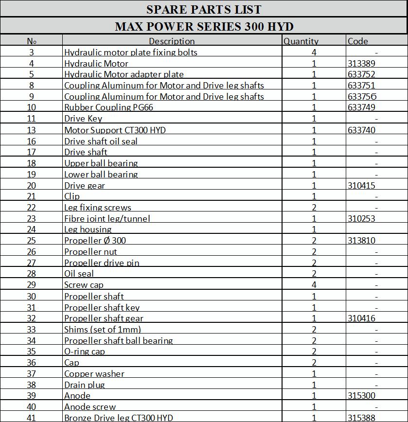
5 4) THE HYDRAULIC MOTOR AND ITS ADAPTER Do not separate the motor from its adapter. Insert the lower drive coupling onto the leg drive shaft (lightly grease the shaft before doing this). Position the red plastic coupling (piece n 10 on Spare Part Diagram ) onto the lower coupling. Before tightening the 2 x 6 mm Allen fixing screws of the lower coupling, make sure that coupling is pushed all the way down on drive leg shaft. Then position the motor and tighten the 4 x 10 mm to 40Nm. IMPORTANT: Please note that the above coupling might need to be adjusted if any other tunnel than a Max Power tunnel (thickness 9mm) is used. The top and bottom coupling pieces should fit tightly together to ensure maximum gripping between them. Check that the propellers turn freely and that there is no tight spot. A certain amount of resistance is normal from the motor. When all is assembled recheck the tightness of all the motor bolts. NOTE: The coupling on the motor side is in place when delivered, do not touch this. 5) PROPELLERS Check the tightness of the oil drain screw (8 mm Allen Key) and the anode (a 10 mm key). IMPORTANT: To prevent limestone deposits from forming (causing damage to the joints), we highly recommend applying silicone grease to the shaft and the joints before assembling the propellers. Fit the fixing pins and propellers NOTE: Position the propeller blades opposed and not in line with one another. Make sure that the propellers turn freely. A certain amount of resistance from the motor is normal. Tighten the 24 mm nuts on each propeller to 27 Nm. Ensure correct protection of hands against the propellers blades. 6) PROTECTION GRILLS With a shallow tunnel installation, we recommend that you protect the propellers by fitting horizontal protection grills. These grills will however modify thruster performance. 7) HYDRAULIC (general remarks) A typical installation of the hydraulic power thruster requires the following elements: oil reservoir/tank hydraulic pump directional control valve hydraulic motor circuit piping oil cooler (depending on type of installation) 4
6 The oil reservoir/tank with return filter and suction strainer should be as close to the pump as possible and on charge. Meaning that the level of the oil should be above the pump, preferably with the oil tank above the water line. For future maintenance, make sure that the return filter is easily accessible. An isolation valve can be fitted to the suction. The pump can be driven by either an internal combustion engine (crankshaft pulley or gearbox PTO) or an electric motor. Depending on the speed and choice of drive, but should always comply with the rated pressure/flow of the thruster. For an internal combustion engine with fixed or variable speed, 3 types of pumps can be used, depending on the unit to be fitted: Direct PTO: Fixed flow pump (***) Variable displacement pump, depending on the model (**) (*) Fixed flow pump with bypass (**) (*) PTO with clutch: Fixed flow pump (**) (*) Variable displacement pump depending on the model (**) (*) Fixed flow pump with bypass (**) (*) On a DC or AC electric motor the following types of pumps can be used: DC MOTOR: Fixed flow pump (*) AC MOTOR: Fixed flow pump or other (**) (*) (***) always require oil cooler (**) require oil cooler when time of operation exceeds 15 minutes, (*) oil cooler not necessary Note: The above choices also depend on capacity of the oil tank etc. The hydraulic directional control valve (DCV) must be equipped with a pressure gauge and pressure relief valve and should preferably be placed as close as possible to the thruster unit. The piping can be flexible or a mix of rigid and flexible type and should have crimp-connected fittings. The piping should match interior diameters and the service pressure equal or above that which has been recommended. The circuits must be as direct as possible and avoid any bends and joints. The circuits must be clean and closed-off until final connection takes place. The thruster hoses arriving at the thruster must be of the thermo-plastic non-conductive type. The hydraulic motor drain line and the return T-line of the DCV should each go separately and directly, back into the top of the oil tank. Use synthetic, mineral or vegetable hydraulic oil, to ISO standard 32 to 48 8) HYDRAULIC SPECIFICATIONS HYD Model 250: Flow = 33/38 litres/min Pressure = 200/220 bars Detailed instructions and diagrams are delivered with each pack, specific to the installation chosen. 5
7 9) HYDRAULIC CUSTOM PACK. Tailor made according to specifications. ELECTRO PUMP PACK: 1 x Electro Pump 24Volt 1 x Power Relay 1 x Fuse Holder 1 x Power Fuse HYDRAULIC CONTROL PACK (12 V / 24 V): 1 Directional Control Valve (Including pressure gauge & Pressure Relieve Valve) 1 Control Panel. RESERVOIR PACK Oil Reservoir 12 / 18 / 40 litres including: Return Filter Suction Strainer Oil Level Sight Gauge/ Thermometer Filler Cap Motor Drain Connection INTERIOR DIAMETERS AND MODULES of the piping between the hydraulic elements: M4 = 1/4 M5 = 5/16 M6 = 3/8 M8 = 1/2 M10 = 5/8 M12 = 3/4 M16 = 1 INTAKE DIAMETERS of standard hydraulic elements MAX POWER: 1 / 2 / 11 = Female BSP 3/4'' 3 / 6 / 7 / 8 / 9 = Female BSP 1/2'', 4 / 5 = Female BSP 3/8'' 10 / 12 = Female BSP 1/4'' M4/5 Directional Control Valve 11 Filter Motor M8 M8 4 5 No Longer than 1.5m If longer increase size. 2 M12/16 Reservoir 1 M8/10 Pump M8/10 3 6
8 10) MAINTENANCE In order to ensure peak performance from your SUPER POWER, the tunnel, the leg and the propellers must be kept clean. IMPORTANT: In order to prevent chalky deposits, which cause damage to the oil seals, we recommend cleaning the shaft and the oil seals first, then applying a layer of silicon oil before assembling the propellers. ANNUAL BASIS: EVERY 5 YEARS: CHANGE the anode (if necessary). CHANGE drive leg oil, if classic (bronze) leg. CHECK the oil and the hydraulic filtration circuit (only if necessary). DRAIN hydraulic oil system and change the filter and refill. THE MAX-POWER TEAM WISHES YOU SUCCESSFUL MANOEUVRING AND ENJOYABLE CRUISING. IT IS IMPORTANT TO KEEP THIS MANUAL ON BOARD! 7
9 Installation Notes 8
10 9
11 300 HYD MAX POWER
12 11
13 12
14 13
15 Super Power Hydraulic: Positioning and Measurements WL E C T D A B Model Dim(mm) A B C D T E Ideal E min Weight 9kg 12kg 20kg 20kg 14
16 Max Power 5, Via Philips Str, 20900, Monza (MI), Italy Tel: +39 (0) , Fax: +39 (0) Introduction The purpose of this document is to set out the terms of warranty cover offered in relation to products purchased by the End User from Max Power or its approved network of resellers. 1. Definitions Authorized Repair Number: The number given by Max Power on reporting a fault with your thruster Dealer: An authorized Max Power sales centre End User: The boat supplied with supplied equipment and the owner thereof Installer: The authorized centre responsible for the installation of your thruster Manufacturer: supplier of the equipment under warranty Pleasure Craft: Vessels used for owner s personal use that have no commercial use (i.e Charter boats or work boats) Resellers: Max Power approved distributors and dealers Serial Number: Number in upper right hand corner of Warranty document Supplier: The manufacturer (Max Power) Warranty: The terms and conditions that are covered by the manufacturer 2. Period of Coverage The equipment manufactured by the Supplier is guaranteed to be free from defective workmanship, components and materials under normal usage conditions for a period of three (3) years from the date of purchase by the End User. This warranty is transferable to subsequent owners of this equipment during the period of coverage. 3. Warranty Registration Register your purchase now at (NB. proof of purchase must be kept throughout the warranty period) 4. Warranty Terms If the material is used for anything other than for pleasure craft, the guarantee is limited to a six-month period. Year 1: All factory testing, diagnosis, repairs and replacements are performed at no charge to the End User; All parts and up to two hours of labour are covered for repairs and replacements conducted in the field. Year 2 & 3: All factory testing, diagnosis, repairs and replacements are performed at no charge to the End User. This excludes any damage or faults occurring from normal wear and tear on the following items: engine, oil seals, relay contacts(if warranty is registered within the 3 month period following installation) 5. Warranty Exclusions Damage due to modifications or installation contrary to published specifications Cost of hauling the boat Damage due to repairs performed by an unauthorized service centre Damage due to lack of normal maintenance services Damage due to water Parts replaced due to normal wear and tear Repairs performed without knowledge of manufacturer (please contact dealer to receive Repair Authorization Number) Tampering of equipment by the End User Cost of travel to and from the job site Cost of economic loss, including injury to any person, damage to property, loss of income or profit, communication, lodging, inconvenience Consequential damage due to failure, including those arising from collision with other vessels or objects 6. Procedural Guidelines PLEASE VIEW THE TROUBLE SHOOTING LIST ON THE MANUAL OF YOUR PRODUCT TO ASCERTAIN OR SOLVE ORIGIN OF PROBLEM PRIOR TO CONTACTING THE DEALER/INSTALLER 1. Contact your dealer/installer to report the problem. If you do not know who this is, contact the nearest Max Power distributor If you are in foreign waters, please contact the nearest Max Power distributor 2. Ensure you have your serial number and model number to hand (top right hand corner of warranty) 3. Dealer/Installer will come to site to decipher the cause of the fault 4. If the cause of fault is due to a manufacturing problem the dealer will contact Max Power to receive Repair Authorization Number. 5. If the problem is due to an installation error please contact your installer. IF POSSIBLE: PLEASE TAKE PHOTOGRAPHS OF THE THRUSTER TO SHOW PROBLEM 7. Service Centers Please go online to find the authorized service station of your area. The warranty as outlined above is only applicable to Max Power manufactured thrusters and optional equipment as used in marine pleasure industry. The supplier holds the exclusive right to test the product and determine whether it is defective 15
Manual CT100 & CT125 April 2008 CT100 12V CT125 24V. With electronic thruster control INSTALLATION OPERATION MAINTENANCE
 CT100 12V CT125 24V With electronic thruster control INSTALLATION OPERATION MAINTENANCE FROM SERIAL NO. 42250 TO 83327 Serial No.: ------------------------------------------------------ Installation date:
CT35 / CT45 With electronic thruster control
 CT35 / CT45 With electronic thruster control INSTALLATION OPERATION MAINTENANCE Serial No.: ------------------------------------------------------ Installation date: -------------------------------------------------
IT IS VERY IMPORTANT TO KEEP THIS MANUAL ON BOARD
 MECHANICAL & ELECTRICAL INSTALLATION GUIDE & MAINTENANCE OVERVIEW Serial N : ---------------------------------------------------- Start up date: ----------------------------------------------- IT IS VERY
VERTICAL RETRACTABLE THRUSTER INSTALLATION OPERATION MAINTENANCE THIS MANUAL MUST BE KEPT ON BOARD AT ALL TIMES
 VERTICAL RETRACTABLE THRUSTER INSTALLATION OPERATION MAINTENANCE THIS MANUAL MUST BE KEPT ON BOARD AT ALL TIMES TABLE OF CONTENTS Number Description Page 1. POSITIONING 3 2. DETERMINE THE LOCATION OF THE
IT IS VERY IMPORTANT TO KEEP THIS MANUAL ON BOARD
 MECHANICAL & ELECTRICAL INSTALLATION GUIDE & MAINTENANCE OVERVIEW Serial N : ---------------------------------------------------- Start up date: ----------------------------------------------- IT IS VERY
Hydraulic Immediate Need Power Pack
 Safety, Operation, and Maintenance Manual WARNING Improper use of this tool can result in serious bodily injury This manual contains important information about product function and safety. Please read
Hydraulic PTO Flow Device
 Safety, Operation, and Maintenance Manual WARNING Improper use of this tool can result in serious bodily injury This manual contains important information about product function and safety. Please read
A copy of this manual must remain on board for consultation.
 MAXPOWER RETRACT R200 FOR BUILT BY DELIVERED A copy of this manual must remain on board for consultation. 1 INSTALLATION MANUAL RETRACT R 200 Last update:december 2014 I. A INTRODUCTION AFTER SALES SERVICE
Boat drive assembly manual
 Boat drive assembly manual Bluefin Dual configuration Design and Manufacture of bespoke electric drive solutions Parts list 1. Boat drive Master controller assembly 2. Boat drive Slave controller assembly
Neptune X6 12/24V SAE 316L Stainless Steel Low Profile Through-Hull Mounted Underwater LED Light Manual
 Neptune X6 12/24V SAE 316L Stainless Steel Low Profile Through-Hull Mounted Underwater LED Light Manual Thank you for purchasing Dr. LED s Neptune X6 underwater LED light. This 1500+ lumen Neptune X6 underwater
Anchormax Vertical Capstan
 Anchormax Vertical Capstan Copyright Vetus-Maxwell APAC Ltd. All rights reserved. Vetus Maxwell APAC Ltd reserves the right to make engineering refinements on all products without notice. Illustrations
Hydraulic Thruster Installation Guide
 Hydraulic Thruster Installation Guide Hydraulic Thruster Installation Guide - Change Log Date Change 03/11/2014 Initial converted release ABT-TRAC 517-A Martin Avenue Rohnert Park, CA 94928 Tel: 707-586-3155
Hydraulic Projects Ltd
 Hydraulic Projects Ltd PC45 Constant Running Marine Autopilot Hydraulic Pump Installation and Service Instructions Serial Number Engineering Excellence FORM_PC45 ISS.4 Released\11 Data Sheets & Manuals\Manuals\Customer
Single Colour Light. TIX202 Interchangeable Flush Fit Thru-Hull Light. Installation and Operation Guide. Rev
 Single Colour Light TIX202 Interchangeable Flush Fit Thru-Hull Light Installation and Operation Guide Rev 3 45-0038 Congratulations! You have purchased a LUMISHORE advanced technology LED underwater light.
Scania Used Vehicle Extended Driveline Warranty
 Scania Used Vehicle Extended Driveline Warranty Scania Dealers supply Approved Used Vehicles with the Scania Used Vehicle Extended Driveline Warranty to first purchasers from the Dealership subject to
SILVERWAKE CONTRACTUAL WARRANTY
 970311098 SILVERWAKE CONTRACTUAL WARRANTY CONTENTS Identification of product and type of warranty applicable...2 SILVERWAKE RECREATIONAL... 3 9 SILVERWAKE PROFESSIONAL... 10 14 SILVERWAKE commissioning
ZF W220. Marine Propulsion Systems
 Marine Propulsion Systems Vertical offset, direct mount marine transmission. Maximum Input** Duty kw hp RPM Medium 253 339 3200 Continuous 213 285 3200 ** Must not be exceeded Description Reverse reduction
ZF W220 Vertical offset, direct mount marine transmission.
 Marine Propulsion Systems Vertical offset, direct mount marine transmission. Maximum Input** Duty kw hp RPM Medium 253 339 3200 Continuous 213 285 3200 ** Must not be exceeded Description Robust design
Contents INTRODUCTION... 2 CHECK YOU HAVE RECEIVED... 4 WHAT YOU WILL NEED...4 TECHNICAL CHARACTERISTICS...5 WIRING DIAGRAMES...6 CABLES...
 Contents Page INTRODUCTION... 2 CHECK YOU HAVE RECEIVED... 4 WHAT YOU WILL NEED...4 TECHNICAL CHARACTERISTICS...5 WIRING DIAGRAMES...6 CABLES...6 BATTERY...7 CHARGE CONTROLLER...8 FUSE...8 TOWERS...8 INSTALLATIONS...9
ZF W650. Marine Propulsion Systems
 Marine Propulsion Systems Vertical offset, direct mount marine transmission. Description Reverse reduction marine transmission with hydraulically actuated multi-disc clutches. Robust design also withstands
SELF PRIMING CHEMICAL SERVICE PUMPS
 SELF PRIMING CHEMICAL SERVICE PUMPS INSTALLATION AND OPERATING INSTRUCTIONS This Manual covers: SELF PRIMING MODEL RANGE J50ECX TO J250ECX STAINLESS STEEL*, and NON METALLIC SEAL PUMP MODEL: SERIAL NO:
ZF 30 M. Marine Propulsion Systems
 Marine Propulsion Systems Vertical offset, direct mount marine transmission. Description Reverse reduction marine transmission with mechanically actuated multi-disc clutches. Suitable for high performance
version 1.0 Installation manual for a Thoosa inboard engine BEFORE COMMENCING THE INSTALLATION, PLEASE READ THIS MANUAL.
 version 1.0 Installation manual for a Thoosa inboard engine BEFORE COMMENCING THE INSTALLATION, PLEASE READ THIS MANUAL. ASMO Marine 1 Index: Thank you for choosing an electric inboard system from Asmo
INSTALLATION AND OPERATING
 Publication T5-704, Rev. 4 Dated: November 1, 2006 INSTALLATION AND OPERATING MANUAL T50-P TURBOTWIN Engine Air Starter AN 99-448 TABLE OF CONTENTS Section Subject Page 1.0 General Information. 1 2.0 Orientation
Air Operated Double Diaphragm Pump. M-Pump ½ Metallic Non Metallic Pump INSTALLATION, OPERATION & MAINTENANCE MANUAL
 Air Operated Double Diaphragm Pump M-Pump ½ Metallic Non Metallic Pump INSTALLATION, OPERATION & MAINTENANCE MANUAL 0.5 I.O.M rev 05. 12/2015 INDEX Title Section Introduction.1 Safety.2 Warranty, General
TWO-STAGE HYDRAULIC PUMP. RWP55-IBT-Air
 ORIGINAL INSTRUCTIONS Form No.1000458 5 SPX Corporation 5885 11th Street Rockford, IL 61109-3699 USA Tech. Services: (800) 477-8326 Fax: (800) 765-8326 Order Entry: (800) 541-1418 Fax: (800) 288-7031 Internet
CROSBY SERIES 800 AND 900 OMNI-TRIM PRESSURE RELIEF VALVES INSTALLATION AND MAINTENANCE INSTRUCTIONS
 any and all liability arising out of the same. Any installation, maintenance, adjustment, repair and testing performed on pressure relief valves should be done in accordance with the requirements of all
Pump Operating and Maintenance Manual - Models
 Pump Operating and Maintenance Manual - Models 78-00111 - 78-0057 Thank you for purchasing the SDI Diaphragm Pump manufactured by Comet Pump. Comet produces quality products which are safe, efficient and
ZF A 7 Down angle, direct mount marine transmission.
 Marine Propulsion Systems 7 Down angle, direct mount marine transmission. Description Robust design also withstands continuous duty in workboat applications. Fully works tested, reliable and simple to
CHAPTER 20: Operation and maintenance
 Pressurized Irrigation Techniques 20.1 CHAPTER 20: Operation and maintenance INTRODUCTION The efficient operation of an irrigation system depends mainly on the ability of the farmer to make the best use
ZF 220. Marine Propulsion Systems
 Marine Propulsion Systems Vertical offset, direct mount marine transmission. Description Robust design also withstands continuous duty in workboat applications. Fully works tested, reliable and simple
ZF 25 MA. Marine Propulsion Systems
 Marine Propulsion Systems 8 Down angle, direct mount marine transmission. Description Reverse reduction marine transmission with mechanically actuated multi-disc clutches. Suitable for high performance
ZF 15 MA. Marine Propulsion Systems
 Marine Propulsion Systems 8 Down angle, direct mount marine transmission. Description Reverse reduction marine transmission with mechanically actuated multi-disc clutches. Suitable for high performance
ZF Marine Propulsion Systems
 Marine Propulsion Systems Vertical offset, direct mount marine transmission. Description Suitable for high performance applications in luxury motoryachts, sport fishers, express cruisers etc. Reverse reduction
AIR COMPRESSOR OPERATING INSTRUCTION AND PARTS LIST
 AIR COMPRESSOR OPERATING INSTRUCTION AND PARTS LIST BELT TYPE IMPORTANT PLEASE MAKE CERTAIN THAT THE PERSON WHO IS TO USE THIS EQUIPMENT CAREFULLY READS AND UNDERSTANDS THESE INSTRUCTIONS BEFORE STARTING
ZF 15 M. Marine Propulsion Systems
 Marine Propulsion Systems Vertical offset, direct mount marine transmission. Description Reverse reduction marine transmission with mechanically actuated multi-disc clutches. Suitable for high performance
ZF 7600 V. Marine Propulsion Systems
 Marine Propulsion Systems 8 V-drive, remote mount marine transmission. Description 3 shaft, reverse reduction transmission with hydraulic clutch mounted on the input shaft and another one mounted on the
TIX402 EOS Installation and Operating Guide
 TIX402 EOS Integrated System TIX402 EOS Installation and Operating Guide Congratulations! You have purchased a LUMISHORE advanced LED technology underwater lighting system. Every care has been taken to
ZF Marine Propulsion Systems
 Marine Propulsion Systems Vertical offset, direct mount marine transmission. Description Reverse reduction marine transmission with hydraulically actuated multi-disc clutches. Suitable for high performance
ZF 25 M. Marine Propulsion Systems
 Marine Propulsion Systems Vertical offset, direct mount marine transmission. Description Reverse reduction marine transmission with mechanically actuated multi-disc clutches. Suitable for high performance
Hydraulic hand-punching tool HS-6. Art convincing solutions
 Hydraulic punching tools INSTRUCTION MANUAL Hydraulic hand-punching tool HS-6 Art. 217602 convincing solutions Contents 1 Technical Data Page 2 2 Safety Instructions Page 2 3 Tool Operation Page 3 3 Tool
Starting up hydraulic systems
 General / Installation A hydraulic system that operates economically, safely, and trouble-free requires careful planning, as well as proper installation and start-up. Conscientious maintenance has a considerable
ZF 45-1 Vertical offset, direct mount marine transmission.
 Marine Propulsion Systems Vertical offset, direct mount marine transmission. Maximum Input** Duty kw hp RPM Pleasure 259 347 5500 Light 250 335 5500 Medium 241 324 5500 Continuous 137 184 3200 ** Must
MODEL NUMBER: MEDIUM DUTY ONBOARD AIR SYSTEM
 MODEL NUMBER: 10003 MEDIUM DUTY ONBOARD AIR SYSTEM IMPORTANT: It is essential that you and any other operator of this product read and understand the contents of this manual before installing and using
Power. On Your Terms.
 Power. On Your Terms. 10 YEAR LIMITED WARRANTY PHI 1310 TM 1 SIMPLIPHI POWER, INC. REV102016 10 YEAR LIMITED WARRANTY: PHI 1310 TM LIMITED PRO-RATED WARRANTY COVERAGE The SimpliPhi Power PHI 1310 as supplied
T1/T2 HYDRAULIC RAM INSTALLATION & SERVICE HANDBOOK
 T1/T2 HYDRAULIC RAM INSTALLATION & SERVICE HANDBOOK SERIAL NUMBER NOTIFICATION The information contained in this document is subject to change without prior notice. Navico UK Ltd. shall not be liable for
INDEX. Company Profile 2-3. Introduction 4. Electric Thruster: System Selection 4. Main Features 5. System Composition 6-7.
 B O W T H R U S T E R S INDEX Company Profile 2-3 Introduction 4 Electric Thruster System Selection 4 Main Features 5 System Composition 6-7 Order Guide 8-9 Accessories 10-12 Hydraulic Thruster System
PARTS LIST RECOMMENDATIONS INSTALLATION TESTING THE FLOW RATE MAINTENANCE PROBLEM SOLVING GUARANTEE. Connection. Cleaning the leaf trap page 28
 C O N T E N T S PARTS LIST page 20 RECOMMENDATIONS page 22 INSTALLATION page 23 Connection page 24 Connecting to the skimmer or one of the skimmers page 24 Connecting to the vacuum point page 25 (overall
STāSIS Engineering R8 Brake System
 STāSIS Engineering R8 Brake System Brake Kit Installation Instruction Application Guide SE811-B30-91-00 R8 Brake System Special Tools Required Qty Description 1 10 MM Allen Head Socket 1 M10 Triple Square
Single Colour Light. TIX301 Interchangeable Flush Fit Thru-Hull Light. Installation and Operation Guide
 Single Colour Light TIX301 Interchangeable Flush Fit Thru-Hull Light Installation and Operation Guide Congratulations! You have purchased a LUMISHORE advanced technology LED underwater light. Every care
CLEAN ROOM DEVICES, LLC "WHERE TUBING AND FITTINGS COME TOGETHER"
 CLEAN ROOM DEVICES, LLC "WHERE TUBING AND FITTINGS COME TOGETHER" CRD600 Automatic Fitting Inserter OPERATIONS MANUAL VERSION 2.1 LAST EDITED 7.25.14 DOCUMENT NUMBER 001 cleanroomdevices.com 1 Table of
ZF 305 A 7 Down angle, direct mount marine transmission.
 Marine Propulsion Systems 7 Down angle, direct mount marine transmission. Description Maximum Input** Duty kw hp RPM Pleasure 617 827 3000 Light 559 749 3000 Medium 426 572 3000 Continuous 388 521 3000
CRD600 Automatic Fitting Inserter
 CRD600 Automatic Fitting Inserter OPERATIONS MANUAL VERSION 2.3 LAST EDITED 12.07.2018 cleanroomdevices.com 1 Table of Contents Title Page.. 1 Table of Contents. 2 1.0 General Product & Safety Information...3
1100 Series. Marine Propulsion Engine M250C and M300C. Powered by Your Needs
 1100 Series Marine Propulsion Engine M250C and M300C These are the latest addition to the common platform concept of 1100 Series diesel engines. Assembled on a new high technology production line, these
ZF 7600 A 8 Down angle, remote mount marine transmission.
 Marine Propulsion Systems 8 Down angle, remote mount marine transmission. Description Maximum Input** Duty kw hp RPM Pleasure 2880 3860 2300 Light 2814 3771 2300 Medium 2471 3311 2300 Continuous 1847 2475
26 - COOLING SYSTEM CONTENTS ENGINE COOLING - DESCRIPTION... 3 ENGINE COOLING - OPERATION... 9 COOLING SYSTEM FAULTS... 1
 26 - COOLING SYSTEM CONTENTS Page LAND ROVER V8 DESCRIPTION AND OPERATION ENGINE COOLING - DESCRIPTION... 3 ENGINE COOLING - OPERATION... 9 FAULT DIAGNOSIS COOLING SYSTEM FAULTS... 1 REPAIR COOLANT - DRAIN
HGV VARIABLE HYDRAULIC GENERATOR SYSTEMS
 Internet: http://www.dynaset.com 00 HGV VARIABLE HYDRAULIC GENERATOR SYSTEMS INSTRUCTIONS Internet: http://www.dynaset.com 00 GENERAL NOTES DYNASET variable hydraulic generator system, especially designed
ZF Marine Propulsion Systems
 Marine Propulsion Systems Vertical offset, direct mount marine transmission. Description Robust design also withstands continuous duty in workboat applications. Fully works tested, reliable and simple
Operating Instructions
 Page 1 of 11 CONTENTS 1 PURPOSE... 3 2 APPLICATION... 3 3 DESCRIPTION... 3 4 FUNCTION... 5 5 TECHNICAL PARAMETERS... 5 6 TYPE IDENTIFICATION KEY MMP... 6 7 DIMENSIONAL DRAWING... 7 8 HYDRAULIC DIAGRAM...
Cable resistance thermometer Model TR40
 Electrical temperature measurement Cable resistance thermometer Model TR40 WIKA data sheet TE 60.40 for further approvals see page 11 Applications For direct installation into the process Machine building
INSTALLATION AND OPERATING MANUAL
 Publication T3-76, Rev. 1 Dated: May 9, 21 INSTALLATION AND OPERATING MANUAL MODEL: T3-I TURBOTWIN Engine Air Starter AN96-419 From Tech Development Inc 68 Poe Ave. Dayton OH 45414 Tel: (937) 898-96 Fax:
SUBMERSIBLE WATER PUMPS
 SUBMERSIBLE WATER PUMPS Model Nos. CS85S - CS85SA CS120S - CS120SA CS185S - CS185SA CS240S - CS240SA CS305S - CS305SA OPERATING & MAINTENANCE INSTRUCTIONS 1000 CONTENTS Warranty conditions... 3 Safety
1000 Series M135 Marine Propulsion Engine 99 kw ( rpm
 Premium engine features for reliability and durability minimises engine down time and service costs. Lowest cost of ownership in its class it pays to compare running costs. Unrivalled worldwide parts and
ZF A 7 Down angle, direct mount marine transmission.
 Marine Propulsion Systems 7 Down angle, direct mount marine transmission. Description Robust design also withstands continuous duty in workboat applications. Fully works tested, reliable and simple to
10 Year Limited Warranty
 Power. On Your Terms. 10 Year Limited Warranty PHI 2.7 TM PHI 3.5 TM 60A SIMPLIPHI POWER, INC. REV020618 10 Year Limited Warranty: PHI 2.7 TM PHI 3.5 TM 60A 24V 48V Limited Pro-Rated Warranty Coverage
Portable Electric/Gas Compressor Operating Instructions
 Portable Electric/Gas Compressor Operating Instructions NOTICE Carefully read this instruction manual before attempting to operate this compressor. MODEL # SERIAL # 1-800-551-2406 TABLE OF CONTENTS Safety
OWNERS MANUAL INSTALLATION AND OPERATING INSTRUCTIONS REPAIR PARTS LIST. Centrifugal Pump Primer MODEL 6D, HAN-DEE PRIMER
 OWNERS MANUAL INSTALLATION AND OPERATING INSTRUCTIONS REPAIR PARTS LIST Centrifugal Pump Primer 383 0893 MODEL 6D, HAN-DEE PRIMER IMPORTANT For best possible performance continuous, satisfactory operation,
Air Actuated Hydraulic Bottle Jack on Wheels
 Operating Instructions & Parts Manual Air Actuated Hydraulic Bottle Jack on Wheels Model Number 18127 18207 Capacity 12 Ton 20 Ton Shinn Fu Co. of America, Inc. 2002 10939 N. Pomona Avenue Kansas City,
ZF 301 C. Marine Propulsion Systems
 Marine Propulsion Systems Co-axial, direct mount marine transmission. Description Robust design also withstands continuous duty in workboat applications. Fully works tested, reliable and simple to install.
series BUTTERFLY VALVE DOUBLE ECCENTRIC FLANGED FAF 3800 PRODUCTION STANDARDS DN100 DN2000 PN Design EN 593 EN ISO Flanged
 PRODUCTION STANDARDS DN100 DN2000 PN 10-16-25 Design EN 593 Connection End Connection EN 1092-2 ISO 7005-2 - Flanged EN 558 Series 14 DIN 3202 F4 Marking EN 19 Tests EN 12266-1 Corrosion Protection Electrostatic
TT Electric Thruster TT 2.0
 TT Electric Thruster 110-140TT 2.0 Owner s Installations, Operation & servicing manual GB 1- Introduction Dear Customer, Thank you for choosing Lewmar. Lewmar products are world renowned for their quality,
SLR / SLR-S/N. Instruction Manual. Walrus America Inc
 SLR / SLR-S/N Instruction Manual Walrus America Inc 1. Installation and Connection 1.1. Pump Installation The pump should be sited in a well ventilated and frost-free position. The distance between pumps-motors
Instruction Manual Extruder Sensor Rheomex 252/254
 Instruction Manual Extruder Sensor Rheomex 252/254 Part No. 002-8632 3-1-014-2 08.1992 Thermo Haake Thermo Haake (USA) Rheo s.a. (France) Dieselstraße 4 53 W. Century Road 99 Route de Versailles D-76227
Innovatech User Manual. Predator 2400 T H E S U R F A C E P R E P A R A T I O N S P E C I A L I S T S
 Innovatech User Manual Predator 2400 T H E S U R F A C E P R E P A R A T I O N S P E C I A L I S T S CONTENTS Introduction... 3 Delivery... 3 Grinder Specifications... 4 Safety Warning... 4 Controls and
Series 867 Reduced Pressure Zone Assemblies
 RP/IS-F-867 INSTALLATION INSTRUCTIONS Series 867 Reduced Pressure Zone Assemblies 2 1 2" 3" (65 80mm) INDEX 867-NRS Installation Instructions....................................... 2-3 Service, Repair
HGS SYSTEM Workshop Manual M103 01
 HGS SYSTEM Workshop Manual M0 0 HGS SYSTEM VERSION.0 EN/0-00 Autobusfabriek BOVA b.v. De Vest 9 5555 XL Valkenswaard The Netherlands Phone: + (0) 40 0846 Fax: + (0) 40 09477 E-mail: basis@bova.nl Website:
ZF 3360 Vertical offset, direct or remote mount marine transmission.
 Marine Propulsion Systems Vertical offset, direct or remote mount marine transmission. Maximum Input** Duty kw hp RPM Pleasure 1791 2400 2450 Light 1635 2191 2450 ** Must not be exceeded Description 3
VADA - V75-S PRODUCT OVERVIEW CONSTRUCTION USAGE LIMITATIONS MOTOR WARRANTY
 PRODUCT OVERVIEW The VADA V75-S submersible pumps are suitable for installation in traditional wells, water deposits, collection tanks, clear watercourses, lakes etc. The V75-S provides a hydraulic system
ZF 85 IV 12 V-drive, direct mount marine transmission.
 Marine Propulsion Systems 12 V-drive, direct mount marine transmission. Maximum Input** Duty kw hp RPM Pleasure 389 522 3500 Light 365 489 3500 Medium 311 416 3500 Continuous 232 311 3200 ** Must not be
1100 Series M250C Marine Propulsion Engine 186 kw ( rpm
 These are the latest addition to the common platform concept of 1106 Series diesel engines. Assembled on a new high technology production line, these ultra clean engines will provide a superior replacement
INSTRUCTION MANUAL & PARTS BOOK. Vibratory Screed
 INSTRUCTION MANUAL & PARTS BOOK Vibratory Screed 200 COMMERCE DRIVE, FREEHOLD, NEW JERSEY, USA, 07728, 732-566-5400 FAX 732-5444 Doc. # OI-M09201 Current Rev. 07 Revised: 11/2013 Orig. Rel.: 06/2014 SAFETY
performance by NEXUS NETWORK Log transducer Installation Manual English
 performance by NEXUS NETWORK Log transducer Installation Manual English LOG TH43 English 10-1 English LOG TH43 This manual is written for NX2 Log transducer 1.00 Edition: September 2002 10-2 LOG TH43 English
ZF 85 A 8 Down angle, direct mount marine transmission.
 Marine Propulsion Systems 8 Down angle, direct mount marine transmission. Description Maximum Input** Duty kw hp RPM Pleasure 501 671 4500 Light 469 628 4500 Medium 376 505 4500 Continuous 222 298 3200
DM-135 DRUM MOWER USER S MANUAL
 DM-135 DRUM MOWER USER S MANUAL 1 DM135 DRUM MOWER INSTRUCTIONS CHAPTER 1 SAFE OPERATION Do not attempt to operate the mower until you have read the operator s manual and all the safety signs on the mower.
TECHNICAL SERVICE MANUAL
 Electronic copies of the most current TSM issue can be found on the Viking Pump website at www.vikingpump.com TECHNICAL SERVICE MANUAL industrial heavy duty motor speed pumps SERIES 4076 AND 4176 SIZES
ZF 301 A 10 Down angle, direct mount marine transmission.
 Marine Propulsion Systems 10 Down angle, direct mount marine transmission. Maximum Input** Duty kw hp RPM Pleasure 385 516 3000 Light 347 465 3000 Medium 273 366 3000 Continuous 204 273 3000 ** Must not
EU DECLARATION CONFORMANCE
 LOGIFLEX ELF / ELFS EU DECLARATION CONFORMANCE Manufacturer: Logitrans A/S Hillerupvej 35 DK-6760 Ribe Denmark It is hereby declared that: Machine: Productgroup: Logiflex Type: ELF/ELFS Year of manufacture/
ZF 3355 Vertical offset, direct or remote mount marine transmission.
 Marine Propulsion Systems Vertical offset, direct or remote mount marine transmission. Maximum Input** Duty kw hp RPM Pleasure 1589 2130 2600 Light 1431 1917 2600 Medium 1239 1660 2600 ** Must not be exceeded
Heavy Duty Engine Cranes
 Heavy Duty Engine Cranes Operating Instructions & Parts Manual Model Number Atd-7484 Atd-7485 (Foldable Legs) Capacity 2 Ton 2 Ton Model Atd-7484 Model Atd-7485 Atd Tools Inc. 160 Enterprise Drive, Wentzville,
ZF 2050 A. Marine Propulsion Systems
 Marine Propulsion Systems 10 Down angle, direct or remote mount marine transmission. Description 3 shaft, reverse reduction transmission with hydraulic clutch mounted on the input shaft and another one
CONTENT. Developed by Volvo Penta 4. Propeller anatomy 5. Duoprop technology 7 PROPELLERS FOR AQUAMATIC. Duoprop for DP280, 290 drives.
 Propeller guide A PERFECT MATCH A correct choice of propeller is absolutely vital to get the most out of your engine and boat. Their performance decides whether the power produced by your engine and drive
 OWNERS MANUAL www.prodriveoutboards.com PO Box 949 129 S Main St. Loreauville, LA PH#: 337-229-0034 FAX#: 337-229-2302 1 TO THE OWNER Thank you for purchasing a Pro-Drive Shallow Water Outboard. Your unit
ZF 220 A. Marine Propulsion Systems
 Marine Propulsion Systems 10 Down angle, direct mount marine transmission. Description Reverse reduction marine transmission with hydraulically actuated multi-disc clutches. Suitable for high performance
ZF Marine Propulsion Systems
 Marine Propulsion Systems Vertical offset, remote mount marine transmission. Description 3 shaft, reverse reduction transmission with hydraulic clutch mounted on the input shaft and another one mounted
ZF 360 A 7 Down angle, direct mount marine transmission.
 Marine Propulsion Systems Description 7 Down angle, direct mount marine transmission. Maximum Input** Duty kw hp RPM Pleasure 875 1172 3000 Light 797 1069 3000 Medium 638 856 3000 Continuous 540 724 3000
ZF A. Marine Propulsion Systems
 Marine Propulsion Systems 7 Down angle, direct mount marine transmission. Maximum Input** Duty kw hp RPM Pleasure 1173 1573 3000 Light 1069 1433 3000 Medium 808 1083 3000 Continuous 745 999 3000 ** Must
Premium Supply. Tilt Deck. Models PCK-TD PCK-PTD. Operator s Manual and Installation Instructions
 Tilt Deck Models PCK-TD PCK-PTD Operator s Manual and Installation Instructions Premium Supply 2038 West Interstate 30 866-934-0777 Proud members of: and June 1, 2015 Table of Contents Introduction...
INSTALLATION MANUAL. Installation Details Warranty Wolfen 122 Wall Bubbler Wolfen 90 Wall Bubbler Wolfen Hob Bubbler
 INSTALLATION MANUAL 252418 Wolfen 122 Wall Bubbler 252465 Wolfen 90 Wall Bubbler 252419 Wolfen Hob Bubbler 252420 Wolfen Remote Button Bubbler Installation Details Warranty CONTENTS Intro 03 Technical
Speedometer log sensor
 Speedometer log sensor Paddlewheel Product reference : 90-60-457 USER GUIDE and INSTALLATION GUIDE nke Sailing competition Z.I. Kerandré Rue Gutenberg 56700 HENNEBONT- FRANCE http://www.nke.fr n indigo
SERVICE MANUAL. Chairman. Playman/Robo
 SERVICE MANUAL Chairman Playman/Robo US How to contact Permobil Permobil Inc. USA 6961 Eastgate Blvd. Lebanon, TN 37090 USA Phone: 800-736-0925 Fax: 800-231-3256 Email: info@permobilusa.com Head Office