G Series Technical Guide 9959 Impeller
|
|
|
- Lionel Harvey
- 5 years ago
- Views:
Transcription

1


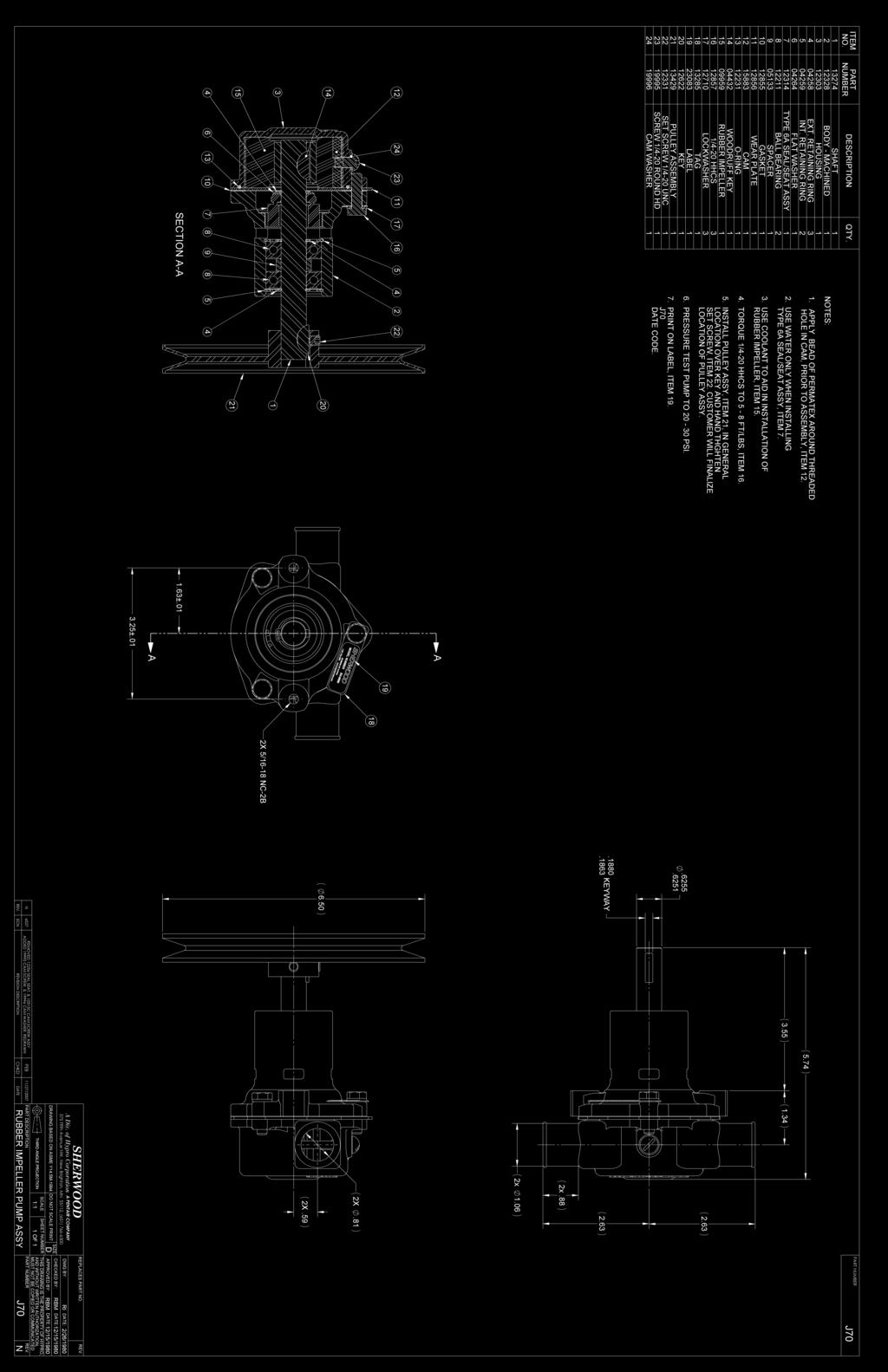
2 The Original Engine Cooling Pump Since G Series Technical Guide 9959 Impeller Identification G30-2 & G30-2B G21 G9901 & G9903* K75 & K75B J70 G15 *(G /2 pulley; G pulley)

3 Assembly / Disassembly Instructions / The following assembly/disassembly procedures apply to all G Series pumps. Deviations from pump to pump are primarily a result of different methods of drive and mounting. Disassembly: A. Remove the screws (1) and lockwashers (2) that hold the body (3) and housing (4) together. B. The housing assembly including the impeller (5) can be removed from the body assembly, along with the o-ring (6), spacer plate (7) and gasket (8). C. Remove the woodruff key (9) from the shaft (10). If the shaft is to be used again, and if it is put in a vise, always use lead over the jaws of the vise so that the shaft is not damaged. D. Remove the retaining ring (11 or 15) from the shaft (impeller end). The shoulder washer (12) and seat assembly (13) can now be removed. E. From the drive end of the pump (pulley end, hub end, shaft end), remove retaining ring, remove pin (17), remove woodruff key (18) and loosen setscrew if used. NOTE: If the pulley (23) or hub (24) is pressed on the shaft, it will be necessary to locate a support directly between the pump body and pulley or hub as close to the shaft as possible. Press the shaft out of the pulley or hub. Make sure the body is free and not supported. F. Remove the large internal retaining ring (16) from the body at the end of the bearing. G. Support the body, and press the shaft, bearings (19), spacer (20) and retaining rings (11) out through the bearing or pulley end of the body. H. The seal assembly (14) is pressed into the body. It can be removed by pushing a tool through the bearing end and up against the metal or back side of the seal. NOTE: On some pumps there is a spacer located between the pulley (hub) and bearing on the shaft. On other pumps, the bearings are positioned on the shaft with a retaining ring on each end. Support the bearings on the inner race, and push the shaft out of the bearings. Assembly: A. When assembling the cam (21), put Permatex #1 on the backside of the cam and the screw (22) that retains the cam. Wipe off any Permatex that gets into the impeller cavity. B. Assemble a retaining ring (11) on the shaft into the second groove from the impeller end. Push the ball bearing (19) over the shaft (10). Press on the inner race of the bearing. Push the bearing up against the retaining ring. Assemble a spacer and then the second ball bearing. Assemble the second retaining ring over the shaft and up against the ball bearing, if required. C. There is a large internal retaining ring (16) located in the body that provides a shoulder for the bearings (approximately 1.38" from the bearing end of the body). If it has been removed, it must be inserted at this time. D. Press the mechanical seal (14) into the body from the impeller end. Make sure that seal is pressed in square. A tool should be used to assure proper assembly. E. Push the bearing and shaft assembly into the body using care not to cock the bearing. A tool is recommended that will give you uniform pressure on the bearing outer race. Lock the bearing in place with the large internal retaining ring. F. Assemble the seat assembly (13), shoulder washer (12) and retaining ring (11 or 15) over the shaft from the impeller end. Locate the white ceramic surface against the seal Do not damage (scratch) the white ceramic surface of the seat, or the seal and seat assembly might leak. Lubricate the rubber part of the seat and use a tool for ease of assembly. G. While supporting the shaft, press the pulley (23) or hub (24) onto the shaft. Secure pulley/hub with pin (17) or key (18) and retaining ring or setscrew as needed. H. Press the woodruff key (9) into the shaft. Make sure the stainless steel key is used at this location. I. Assemble the impeller (5) into the housing (4). 1
4 Assembly / Disassembly Instructions (continued) J. Assemble the gasket (8) and spacer plate (7) on the body (3), and line up the screw holes. Replace the lockwashers (2) and tighten the screws (1). K. Make sure the o-ring (6) is properly located in the groove in the housing. A small dab of grease will help hold it in position until the housing to body screws are tightened. Sherwood # G15 G21 G30-2B G30-2 G9901 G9903 J70 K75B Engine Manufacturer Chris Craft Chris Craft Chris Craft Volvo/OMC Volvo/OMC Commander Engine Model &8 Cyl 4 Cyl 302&351 ITEM QTY CM Screw Lockwasher Body Housing Impeller O-ring End Plate Gasket Key Shaft Retaining Ring (Ext) 2/ Washer Retaining Ring (Ext) Retaining Ring (Int) Pin Key Ball Bearing Spacer Cam Cam Screw Drive Pulley or Gear Hub /14 Water Seal/Seat Assy Minor Repair Kit Major Repair Kit Inspection The #1 reason for premature engine wear is overheating. To maintain engine performance, insist upon genuine Sherwood impellers and service kits. Recommended inspection to be performed at any service interval: Impeller Wear Plate Cam Cover Inspect for cracks or tears. Also, inspect for excessive abrasion of vane ends. Replace annually, or if any of the conditions exist, as in the picture below.* Inspect for wear, flatness, and pin for fatigue. Replace at minor and major pump rebuild or if wear is evident to maintain pump flow and suction performance. Pitting Replace at major pump rebuild or if pitting/wear is evident. Mechanical Seal Replace at major pump rebuild or if wear exists to maintain pump flow and suction performance..... Replace at minor and major pump rebuild or if leaking. Lip Seal Replace at minor and major pump rebuild or if leaking. Shaft Bearing Inspect for wear in area of lip seal and rubber impeller. Grooving of lip seal area or heavy fretting of the impeller end shaft will require shaft replacement Inspect for loss of grease, corrosion or rough rotation. Replace at major pump rebuild or if in doubt. * See maintenance schedule on back page Bead Worn To A Flat Ripped Vane Cavitation Tear Bowed (set) 2
5 Preventative Maintenance Pleasure Boating Commercial/Fishing Use Maintenance (Low Hours) (High Hours) Schedule Light Duty Severe Duty Heavy Duty Severe Duty (High RPM, Silt or Sand) (High RPM, Silt or Sand) Impeller Kit Every year 6 months 6 months 3 months Minor Kit 2 years Every year Every year 6 months Major Kit 4 years 2 years 2 years Every year Impeller Kit Minor Kit Major Kit 09959K Impeller Impeller Impeller O-Ring O-Ring O-Ring Gasket Gasket Gasket Seal Seal Snap Ring Snap Ring Key Key Washer Washer Snap Rings Snap Rings Bearings End Plate Cam Cam Screw G15 X X X G21 X X X G30-2B X X X G30-2 X X X G9901 X X X G9903 X X X G55-2 X X X J70 X X X K75B X X X 7/05 Form L-3047
G Series Technical Guide Impeller
 The Original Engine Cooling Pump Since 1921 www.sherwoodpumps.com G Series Technical Guide 10615 Impeller Identification G5, G7, G7B & G50 G45-1 G45-2 & G46 M70 & M71 L10B K90 Assembly / Disassembly Instructions
SHERWOOD A Div. of Hypro Corporation A PENTAIR COMPANY 375 Fifth Avenue NW, New Brighton, MN 55112, (651) SIZE C SHEET NUMBER 1 OF 1
 SIZE C SHEET NUMBER 1 OF 1") ITEM NO. PART NUMBER DESCRIPTION QTY. 1 854 SHAFT 1 1510 BODY 1 10596 HOUSING 1 4 1079 COVER 1 5 1085 CAM 1 6 105 CAM SCREW 10-NFT 1 7 107 FIBRE GASKET 1 8 1086 FIBRE GASKET 1 9 0075 BUSHING - GRAPHITE
ITEM NO. PART NUMBER DESCRIPTION QTY. 1 854 SHAFT 1 1510 BODY 1 10596 HOUSING 1 4 1079 COVER 1 5 1085 CAM 1 6 105 CAM SCREW 10-NFT 1 7 107 FIBRE GASKET 1 8 1086 FIBRE GASKET 1 9 0075 BUSHING - GRAPHITE
27000 Pump Series Technical Guide
 The Original Engine Cooling Pump Since 1921 www.sherwoodpumps.com 27000 Pump Series Technical Guide Identification P2701-01, P2704-01, P2708-01 P2703-01, P2705-01, P2709-01 P2701X, P2702-01, P2706-01,
18000 Pump Series Technical Guide
 The Original Engine Cooling Pump Since 1921 www.sherwoodpumps.com 18000 Pump Series Technical Guide Identification G1801 and G1805 G1807 and G18071-01 G1804, G1806 and G18061-01 G1808, G18081-01, G18082-01
18000 Pump Series Technical Guide
 The Original Engine Cooling Pump Since 1921 www.sherwoodpumps.com 18000 Pump Series Technical Guide Identification G1801 and G1805 G1807 and G18071-01 G1804, G1806 and G18061-01 G1811-01 G1808, G18081-01,
26000 Pump Series Technical Guide
 The Original Engine Cooling Pump Since 1921 www.sherwoodpumps.com 26000 Pump Series Technical Guide Identification G2601-01, G2603-01 Note: G2603-01 has an integrated cam. (There is no cam screw as the
4.2 WATER PUMP (GEAR CASE MOUNTED AND LATER) (GCM)
 (GCM)") SERIES 60 SERVICE MANUAL 4.2 WATER PUMP (GEAR CASE MOUNTED - 1991 AND LATER) (GCM) The centrifugal-type water pump circulates the engine coolant through the cooling system. The pump is mounted on the rear
SERIES 60 SERVICE MANUAL 4.2 WATER PUMP (GEAR CASE MOUNTED - 1991 AND LATER) (GCM) The centrifugal-type water pump circulates the engine coolant through the cooling system. The pump is mounted on the rear
INSTRUCTIONS FOR OVERHAUL OF RAMEY RE SERIES WINCH
 INSTRUCTIONS FOR OVERHAUL OF RAMEY RE 12000 SERIES WINCH DISASSEMBLY 1. Drain oil from gear housing by removing plug # from bottom of gear housing. Remove relief fitting # and reducer # from top of gear
Maintenance Information
 16606022 Edition 3 May 2014 Air Drill 728 Series Maintenance Information Save These Instructions Product Safety Information WARNING Failure to observe the following warnings, and to avoid these potentially
Maintenance Information
 45528270 Edition 1 June 2007 Barring Motor T480 Series Maintenance Information Save These Instructions WARNING Always wear eye protection when operating or performing maintenance on this Barring Motor.
Pneumatic Axial Die Grinder also for Underwater Use Type , 0050
 M a s c h i n e n f a b r i k G m b H Pneumatic Axial Die Grinder also for Underwater Use Type 1 5077 0010 0020, 0050 Illustration can differ from the original Repair Manual and Compiled: 18.07.11 150770010_0020_0050_Inst_en_Version_00
NOTE: Visit our website at for video repair procedures, under the Tools section.
 Repair Instructions Hypro Repair Tools: Tool Box No. 3010-0168 1/4" Allen Wrench No. 3020-0008 Support Bars (2) No. 3010-0064 Port Brush No. 3010-0066 1/16" Allen Wrench No. 3020-0009 Brush Holder No.
Gear Products Inc N. 161st E. Ave. Tulsa, OK Phone (918) Fax (918)
 Fax (918)") SERVICE MANUAL Disassembly & Assembly Procedures Worm Gear Swing Drive 003 Series Gear Products Inc. 1111 N. 161st E. Ave. Tulsa, OK 74116 Phone (918) 234-3044 Fax (918) 234-3455 Worm Gear Swing Drive
SERVICE MANUAL Disassembly & Assembly Procedures Worm Gear Swing Drive 003 Series Gear Products Inc. 1111 N. 161st E. Ave. Tulsa, OK 74116 Phone (918) 234-3044 Fax (918) 234-3455 Worm Gear Swing Drive
Zoom and Print Options
 1 of 63 8/26/2017, 7:04 AM Vehicle» Transmission and Drivetrain» Transfer Case» Service and Repair» Procedures» Isuzu T150» Overhaul (Unit Repair)» 1. Transfer Case Disassemble Transfer Case Disassemble
8 TROUBLESHOOTING
 8 DRIVE AND DRIVEN PULLEYS/ SCHEMATIC DRAWING------------------------------------------------------------------------- 8-1 SERVICE INFORMATION-----------------------------------------------------------------------
Maintenance Information
 45761848 Edition 3 February 2014 Air Die Grinder AC4A, SC4A and XC4A Series Maintenance Information Save These Instructions Product Safety Information WARNING Failure to observe the following warnings,
Maintenance Information
 04581245 Edition 2 May 2014 Air Grinder, Die Grinder and Sander Series G2 (Angle) Maintenance Information Save These Instructions Product Safety Information WARNING Failure to observe the following warnings,
DRIVE SHAFT & FRONT AXLE
 DRIVE SHAFT & FRONT AXLE Return To Main Table of Contents GENERAL... 2 DRIVE SHAFT... 6 HUB AND KNUCKLE... 13 FRONT AXLE... 15 GENERAL GENERAL SPECIFICATIONS Drive shaft Joint type Outer Inner Length (Joint
INSTRUCTION MANUAL AND PARTS LIST FOR 3SIC AND 4SIC SERIES PUMPS
 TM INSTRUCTION MANUAL AND PARTS LIST FOR 3SIC AND 4SIC SERIES PUMPS WARNING This manual, and General Instructions Manual, CA-1 should be read thoroughly prior to pump installation, operation or maintenance.
Maintenance Information
 80234313 Edition 2 May 2014 Air Grinder, Die Grinder, Sander and Belt Sander Series G1 (Angle) Maintenance Information Save These Instructions Product Safety Information WARNING Failure to observe the
HYDRAULICS. TX420 & & lower. Hydraulic Tandem Pump Removal. 4. Remove the LH side panel (Fig. 0388).
.") TX420 & 425 240000299 & lower 4. Remove the LH side panel (Fig. 0388). Hydraulic Tandem Pump Removal Note: Cleanliness is a key factor in a successful repair of any hydraulic system. Thoroughly clean all
TX420 & 425 240000299 & lower 4. Remove the LH side panel (Fig. 0388). Hydraulic Tandem Pump Removal Note: Cleanliness is a key factor in a successful repair of any hydraulic system. Thoroughly clean all
Product Service Manual For DLH12DHT SERIES PUMPS
 Product Service Manual For DLH12DHT SERIES PUMPS Pump Size Bill of Material Assembly Drawing 275 3217 / 568 - DLH12DHTX-275 Figure 3 312 3220 / 561 - DLH12DHT 312 Figure 3 3220 / 567 - DLH12DHT - 312 P
DESCRIPTION SPECIFICATIONS
 Please read and save this Repair Parts Manual. Read this manual and the General Operating Instructions carefully before attempting to assemble, install, operate or maintain the product described. Protect
Maintenance Information
 16575219 Edition 4 October 2013 Air Screwdrivers QP1P, QP1S and QP1T Series Maintenance Information Save These Instructions Product Safety Information WARNING Failure to observe the following warnings,
8. DRIVE AND DRIVEN PULLEYS/
 8 DRIVE AND DRIVEN PULLEYS/ SCHEMATIC DRAWING ---------------------------------------------- 8-1 SERVICE INFORMATION -------------------------------------------- 8-2 TROUBLESHOOTING -------------------------------------------------
1988 Chevrolet Pickup V SUSPENSION - FRONT (4WD)' 'Front Suspension - "V" Series 1988 SUSPENSION - FRONT (4WD) Front Suspension - "V" Series
' 'Front Suspension - V Series 1988 SUSPENSION - FRONT (4WD) Front Suspension - V Series") 1988 SUSPENSION - FRONT (4WD) Front Suspension - "V" Series DESCRIPTION NOTE: Vehicle serial numbers used in this article has been abbreviated for common reference to Chevrolet and GMC models. Chevrolet
1988 SUSPENSION - FRONT (4WD) Front Suspension - "V" Series DESCRIPTION NOTE: Vehicle serial numbers used in this article has been abbreviated for common reference to Chevrolet and GMC models. Chevrolet
Maintenance Information
 16575128 Edition 2 May 2014 Air Grinder, Sander or Polisher 77A Series Maintenance Information Save These Instructions Product Safety Information Failure to observe the following warnings, and to avoid
Bronze Close-Coupled Self-Priming Flexible Impeller Pumps
 Please read and save this Repair Parts Manual. Read this manual and the General Operating Instructions carefully before attempting to assemble, install, operate or maintain the product described. Protect
MAINTENANCE CLEANING. MECHANICAL SEAL REPLACEMENT Refer to figures 1 and 2. SHIM ADJUSTMENT
 Please read and save this Repair Parts Manual. Read this manual and the General Operating Instructions carefully before attempting to assemble, install, operate or maintain the product described. Protect
1. Remove the parking brake assembly. 2. Remove the 4 bolts holding the yoke flange and drum. Remove the yoke flange and drive.
 Disassembly NOTE: To replace the brake assembly, brake shoe and lining assemblies, or other operational components the complete parking brake assembly must be removed from the vehicle. 1. Remove the parking
Transmission Overhaul Procedures-Bench Service
 How to Assemble the Lower Reverse Idler Gear Assembly Special Instructions In 1996 Eaton changed the reverse idler system design. In the nut design, the reverse idler bearing was lubricated through a hole
INSTRUCTION MANUAL AND PARTS LIST FOR PG/RG3D_-187, 218, 250 and 312 SERIES PUMPS
 INSTRUCTION MANUAL AND PARTS LIST FOR PG/RG3D_-187, 218, 250 and 312 SERIES PUMPS WARNING This Instruction Manual and General Instructions Manual, CA-1, should be read thoroughly prior to pump installation,
Maintenance Information
 80234313 Edition 1 June 2006 Air Grinder, Die Grinder, Sander and Belt Sander Series G1 (Angle) Maintenance Information Save These Instructions WARNING Always wear eye protection when operating or performing
Pneumatic Angle Grinder also for Underwater Use Type
 M a s c h i n e n f a b r i k G m b H Pneumatic Angle Grinder also for Underwater Use Type 1 4311 0050 Illustration can differ from the original Repair Manual and Spare Parts List Compiled: 22.06.11 143110050_Inst_en_Version_00
TC20 Chain Driven Power Take-Off Overhaul Instructions
 TC20 Chain Driven Power Take-Off Overhaul Instructions Table of Contents Section Page Introduction 4 Ordering Repair Parts 4 General Information 5 Special Tools 6 Disassembly See Page 2 Reassembly See
Fig. 1: Exploded view of the 2WD hub and bearings
 Page 1 of 8 Front Wheel Bearings REPLACEMENT NOTE: Sodium-based grease is not compatible with lithium-based grease. Read the package labels and be careful not to mix the two types. If there is any doubt
PRODUCT SERVICE MANUAL. BK6DHZ(C)-250, 275, 312 and 400 PUMPS
-250, 275, 312 and 400 PUMPS") PRODUCT SERVICE MANUAL BK6DHZ(C)-250, 275, 312 and 400 PUMPS WARNING This manual, and the GENERAL INSTRUCTION MANUAL, SRM00046, should be read thoroughly prior to pump installation, operation or maintenance.
PRODUCT SERVICE MANUAL BK6DHZ(C)-250, 275, 312 and 400 PUMPS WARNING This manual, and the GENERAL INSTRUCTION MANUAL, SRM00046, should be read thoroughly prior to pump installation, operation or maintenance.
Wheel end bearing and seal installation guide. Automotive edition Featuring front and rear wheel drive models
 Wheel end bearing and seal installation guide Automotive edition Featuring front and rear wheel drive models Introduction Contents The SKF Seal and Bearing lnstallation Guide (SKF #457809) covers the removal
GT SERIES WET PRIME PUMPS SERVICE MANUAL
 SERVICE MANUAL BEFORE GETTING STARTED This manual is intended as a guide to disassembly and reassembly of a Pioneer Pump. It is to be used only by trained and experienced service technicians who are familiar
ALLDATA Online Lexus LS 400 V8-4.0L (1UZ-FE) - Front. Front
 - Front. Front") Page 1 of 18 Home Account Contact ALLDATA Log Out Help PAUL REDEHOFT Select Vehicle New TSBs Technician's Reference Component Search: OK 1991 Lexus LS 400 V8-4.0L (1UZ-FE) Conversion Calculator Vehicle
Page 1 of 18 Home Account Contact ALLDATA Log Out Help PAUL REDEHOFT Select Vehicle New TSBs Technician's Reference Component Search: OK 1991 Lexus LS 400 V8-4.0L (1UZ-FE) Conversion Calculator Vehicle
9. DRIVE AND DRIVEN PULLEYS/ KICK STARTER AGILITY ~6.0kg-m g-m g-m 9-0
 9 5.0~6.0kg-m 3.5-4.5g-m 9 3.5-4.0g-m 9-0 SERVICE INFORMATION...9-1 DRIVE BELT...9-5 TROUBLESHOOTING...9-1 DRIVE PULLEY...9-6 LEFT CRANKCASE COVER...9-2 CLUTCH/DRIVEN PULLEY...9-9...9-2 SERVICE INFORMATION
PRODUCT SERVICE MANUAL FOR _G3D -350 and 400 SERIES PUMPS (Idler Cup and Hydrostatic Thrust Designs)
") PRODUCT SERVICE MANUAL FOR _G3D -350 and 400 SERIES PUMPS (Idler Cup and Hydrostatic Thrust Designs) WARNING The Imo General Installation Operation, Maintenance, and Troubleshooting Manual, (No. SRM00046),
PRODUCT SERVICE MANUAL FOR _G3D -350 and 400 SERIES PUMPS (Idler Cup and Hydrostatic Thrust Designs) WARNING The Imo General Installation Operation, Maintenance, and Troubleshooting Manual, (No. SRM00046),
REMOVE FRONT WHEEL RH
 518 OVERHAUL POWER STEERING Do not overtighten when using a vise. When installing, coat the parts indicated by the arrows with power steering fluid (see page 517 ). 1. REMOVE FRONT WHEEL RH 2. DRAIN POWER
PRODUCT SERVICE MANUAL FOR BK12DHZ PUMPS
 PRODUCT SERVICE MANUAL FOR BK12DHZ PUMPS WARNING This manual, and the GENERAL INSTRUCTION MANUAL SRM00046, should be read thoroughly prior to pump installation, operation or maintenance. Manual No. SRM00095
OPERATION, MAINTENANCE AND OVERHAUL INSTRUCTIONS FOR PB18 SERIES PORTABLE PUMPS
 WATEROUS COMPANY Form No. F 2058 South St. Paul, Minnesota 55075 January, 1992 OPERATION, MAINTENANCE AND OVERHAUL INSTRUCTIONS FOR PB18 SERIES PORTABLE PUMPS Printed in U.S.A. Waterous Company F 2058
INSTRUCTION MANUAL AND PARTS LIST FOR 3G SERIES PUMPS SIZES 95 THROUGH 162
 TM INSTRUCTION MANUAL AND PARTS LIST FOR 3G SERIES PUMPS SIZES 95 THROUGH 162 This instruction manual is now identified as SRM00020 WARNING This Special Instruction Manual and General Instructions Manual,
1.28 ACCESSORY DRIVE. Accessory Drive Assembly Related Parts (Former Design) SERIES 60 SERVICE MANUAL. 1. Locknut 8. Drive Gear
 SERIES 60 SERVICE MANUAL. 1. Locknut 8. Drive Gear") SERIES 60 SERVICE MANUAL 1.28 ACCESSORY DRIVE The accessory drive assembly is mounted to the front of the gear case cover and utilizes a two-groove pulley to drive the alternator. See Figure 1-413, and
SERIES 60 SERVICE MANUAL 1.28 ACCESSORY DRIVE The accessory drive assembly is mounted to the front of the gear case cover and utilizes a two-groove pulley to drive the alternator. See Figure 1-413, and
TIMING CHAIN. TIMING CHAIN Removal and Installation EM-35 PFP:13028 EBS00I2X KBIA2511E
 TIMING CHAIN Removal and Installation PFP:13028 EBS00I2X A EM C D E F G H I J K L M KBIA2511E EM-35 1. Camshaft sprocket (left bank EXH) 2. Camshaft sprocket (left bank INT) 3. Camshaft sprocket (right
Maintenance Instructions
 General Note These instructions contain information common to more than one model of Bevel Gear Drive. To simplify reading, similar models have been grouped as follows: GROUP 1 Models 11, 0, 1,, (illustrated),,
AIRGO MISTING SYSTEM MAINTENANCE
 AIRGO MISTING SYSTEM MAINTENANCE WARNING: Disconnect the fan and misting pump from power before servicing. Service schedule Schedule Procedure 50 hours of operation Initial oil change 300 hours of operation,500
Installation and Service Instructions. ST Series Pumps
 Installation and Service Instructions ST Series Pumps! WARNING READ MANUAL before operating or working on a Tuthill ST Series pump. Page 2 of 24 4/24/03 Table of Contents Page 4 Page 5 Page 5 Page 6 Page
354 CHAPTER EIGHT WATER PUMP
 354 CHAPTER EIGHT 33 Shift handle F : Forward N : Neutral R : Reverse proper alignment of the water tube to the water pump opening during each installation attempt. Make sure the locating pins enter the
Maintenance Information
 16573370 Edition 2 February 2014 Air Grinder 99V Series Maintenance Information Save These Instructions Product Safety Information WARNING Failure to observe the following warnings, and to avoid these
AT Clutch Major Service Sizes 25, 55, 115
 P-1404 819-0324 AT Clutch Major Service Sizes 25, 55, 115 Installation Instructions Contents Introduction............................ 2 Warranty....................... back cover Failure to follow these
1. Remove the crankshaft pulley, engine coolant pump pulley and drive belt. 2. Remove the timing belt cover.
 DISASSEMBLY 1. Remove the crankshaft pulley, engine coolant pump pulley and drive belt. 2. Remove the timing belt cover. 3. Turn the crankshaft clockwise and align the timing marks so as to bring the No.
Models Series Series
 PumpAgents.com - Click here for Pricing/Ordering Models 11860-Series 11870-Series SELF-PRIMING PUMPS ELECTRO-MAGNETIC CLUTCH UNIT FEATURES Body: Impeller: Shaft: Seal: Ports: Bearings: Weight: Bronze Nitrile
Maintenance Information
 16573347 Edition 2 February 2014 Air Grinder Series 88H Maintenance Information Save These Instructions Product Safety Information WARNING Failure to observe the following warnings, and to avoid these
Overhaul Instructions. S100 Series Centrifugal Fire Pumps. Table of Contents F /22/02 1/19/18
 S100 Series Centrifugal Fire Pumps Overhaul Instructions Form No. F-1031 Section 4219 Issue Date 02/22/02 Rev. Date 1/19/18 Table of Contents Section Page Introduction 4 Ordering Repair Parts 4 Pump Models
SA 8 FRONT AXLE HUB COMPONENTS
 SA8 FRONT AXLE HUB COMPONENTS SA9 REMOVAL OF FRONT AXLE HUB 1. REMOVE COTTER PIN, LOCK NUT CAP AND BEARING LOCK NUT (a) Remove the cotter pin and lock nut cap. (b) Loosen the bearing lock nut while depressing
DISASSEMBLY AND ASSEMBLY
 211-02-1 Power Steering 211-02-1 DISASSEMBLY AND ASSEMBLY Steering Gear Special Tool(s) Holding Fixture, Transmission 307-003 (T57L-500-B) Special Tool(s) Installer, Worm Bearing Locknut 211-012 (T66P-3553-B)
Maintenance Information
 16572554 Edition 2 May 2014 Air Drill 44SMA, 44SMA-EU Maintenance Information Save These Instructions Product Safety Information WARNING Failure to observe the following warnings, and to avoid these potentially
GENESIS COUPE(BK) > 2010 > G 3.8 DOHC > Steering System
 > 2010 > G 3.8 DOHC > Steering System") GENESIS COUPE(BK) > 2010 > G 3.8 DOHC > Steering System Steering System > General Information > Specifications Specifications Steering gear Oil pump Steering angle Power steering oil Item Specification
GENESIS COUPE(BK) > 2010 > G 3.8 DOHC > Steering System Steering System > General Information > Specifications Specifications Steering gear Oil pump Steering angle Power steering oil Item Specification
Section Periodic Inspection and Lubrication (At First 25 Hours, First 50 Hours, First 100 Hours and Subsequently at 100-Hour Intervals)
") Airmaster Propellers Ltd Variable Pitch Constant Speed Propellers for Light Aircraft Airmaster Propellers Ltd Unit B, 144 Central Park Dr PO Box 21220, Henderson Auckland, New Zealand Ph: +64 9 8360065
Airmaster Propellers Ltd Variable Pitch Constant Speed Propellers for Light Aircraft Airmaster Propellers Ltd Unit B, 144 Central Park Dr PO Box 21220, Henderson Auckland, New Zealand Ph: +64 9 8360065
Installation, Operation and Maintenance Manual SCP/SFP SELF PRIMING PUMPS
 Installation, Operation and Maintenance Manual SCP/SFP SELF PRIMING PUMPS IMPORTANT - WARRANTY CLAUSE ROTECH PUMPS: Pumps manufactured & assembled by Rotech, are covered by warranty for free of manufacturing
INSTRUCTION MANUAL AND PARTS LIST FOR SERIES 8L-630J AND 630M WARNING
 INSTRUCTION MANUAL AND PARTS LIST FOR SERIES 8L-630J AND 630M WARNING READ CA-l AND TIDS INSTRUCTION MANUAL PRIOR TO INSTALLATION, OPERATION OR MAINTENANCE WARNING This Instruction Manual and General Instructions
Rineer 15 Series Hydraulic Motor Service Manual
 Section 4-2 Rineer 15 Series Hydraulic Motor Service Manual Removal of 15 Series Shaft Seal Step 1 Remove snap ring. See Figure 1. WARNING: Use caution when removing snap ring. If released accidentally,
DESCRIPTION MAINTENANCE
 Specifications Information and Repair Parts Manual 316F-95 and 316F-99 Please read and save this Repair Parts Manual. Read this manual and the General Operating Instructions carefully before attempting
TROUBLESHOOTING. Avoid getting grease and oil on the drive belt and pulley faces.
 8 KICK STARTER/DRIVE PULLEY/ SERVICE INFORMATION... 8-2 TROUBLESHOOTING... 8-2 LEFT CRANKCASE COVER... 8-3 DRIVE PULLEY... 8-3... 8-7 KICK STARTER... 8-14 0 1 SERVICE INFORMATION GENERAL INSTRUCTIONS Avoid
BRAKE SYSTEM Return To Main Table of Contents
 BRAKE SYSTEM Return To Main Table of Contents GENERAL... 2 BRAKE PEDAL... 10 MASTER CYLINDER... 13 BRAKE BOOSTER... 16 BRAKE LINE... 18 PROPORTIONING VALVE... 19 FRONT DISC BRAKE... 20 REAR DRUM BRAKE...
Maintenance Information
 16573321 Edition 3 February 2014 Air Grinder Series 61H Maintenance Information Save These Instructions Product Safety Information WARNING Failure to observe the following warnings, and to avoid these
Wyco Tool Company CHAPTER 1 GENERAL INFORMATION. a) Purpose of Vibration
 Purpose of Vibration") CHAPTER 1 GENERAL INFORMATION a) Purpose of Vibration The use of internal vibration is required to improve the workability of low slump concrete used in slip form paving. Low slump concrete reduces edge
CHAPTER 1 GENERAL INFORMATION a) Purpose of Vibration The use of internal vibration is required to improve the workability of low slump concrete used in slip form paving. Low slump concrete reduces edge
Maintenance Information
 Form 16573321 Edition 1 July 2004 Air Grinder Series 61H Maintenance Information Save These Instructions Always wear eye protection when operating or performing maintenance on this tool. Always turn off
INSTRUCTION MANUAL AND PARTS LIST FOR PG/RG3D-275 SERIES PUMPS (Idler Cup and Hydrostatic Thrust Designs)
") TM INSTRUCTION MANUAL AND PARTS LIST FOR PG/RG3D-275 SERIES PUMPS (Idler Cup and Hydrostatic Thrust Designs) WARNING This Instruction Manual and General Instructions Manual, CA-1, should be read thoroughly
TM INSTRUCTION MANUAL AND PARTS LIST FOR PG/RG3D-275 SERIES PUMPS (Idler Cup and Hydrostatic Thrust Designs) WARNING This Instruction Manual and General Instructions Manual, CA-1, should be read thoroughly
1990 SUSPENSION Front ES250, LS400
 SUSPENSION - FRONT Article Text 1990 Lexus LS 400 For Lextreme Copyright 1998 Mitchell Repair Information Company, LLC Thursday, January 29, 2004 04:56PM ARTICLE BEGINNING 1990 SUSPENSION Front ES250,
INSTRUCTION AND REPAIR MANUAL MODELS 341A, 342A AND 344A 6
 SECTION 6 ITEM 0 DATED JUNE 1998 SUPERSEDES ITEMS 1, 2, DATED MARCH 1992 INSTRUCTION AND REPAIR MANUAL MODELS 1A, 2A AND A 6 NOTE This repair manual is applicable to pump Models 1A, 2A and A. All photos
1/2" AIR DRIVEN DIAPHRAGM PUMP
 1/2" DRIVEN DIAPHRAGM PUMP OPERATION AND SERVICE GUIDE O-1225D NOV. 2008 Page 1 of 6 Refer to Bulletin P-605, Parts List P-9151 DRIVEN, DOUBLE DIAPHRAGM PUMP MANUAL Congratulations on purchasing one of
Binks MODELS & AGITATOR DRIVE UNITS
 Binks MODELS 31-393 & 31-394 AGITATOR DRIVE UNITS for Agitator Equipped Drum MODEL 31-393 Includes the following items: 1, 2, and 3. 1 MODEL 31-394 shown. 17 4 3 2 12 13 14 15 2 3 8 5 9 11 8 10 6 7 17
SUSPENSION - FRONT Infiniti G20 DESCRIPTION ADJUSTMENTS & INSPECTION SUSPENSION Front G20
 SUSPENSION - FRONT 1992 Infiniti G20 1991-92 SUSPENSION Front G20 DESCRIPTION G20 uses a 4-wheel independent multi-link suspension system. Transverse links are connected to bottom of steering knuckle.
TRANSMISSION AND TRANSFER CASE
 TJ TRANSMISSION AND TRANSFER CASE 21-1 TRANSMISSION AND TRANSFER CASE TABLE OF CONTENTS page MANUAL TRANSMISSION - NSG370...1 AUTOMATIC TRANSMISSION - 42RLE...37 page TRANSFER CASE - NV231...165 TRANSFER
CLUTCH CONTENTS SERVICE DIAGNOSIS. (a) Worn or damaged disc assembly. (b) Grease or oil on disc facings. (c) Improperly adjusted cover assembly.
 Worn or damaged disc assembly. (b) Grease or oil on disc facings. (c) Improperly adjusted cover assembly.") CLUTCH CONTENTS -GROUP 6 Page CLUTCH HOUSING ALIGNMENT... 6 CLUTCH PEDAL FREE PLAY 1 CLUTCH RELEASE BEARING 5 CLUTCH RELEASE FORK... 5 CLUTCH SERVICING 2 PILOT BUSHING CRANKSHAFT TO TRANSMISSION DRIVE
CLUTCH CONTENTS -GROUP 6 Page CLUTCH HOUSING ALIGNMENT... 6 CLUTCH PEDAL FREE PLAY 1 CLUTCH RELEASE BEARING 5 CLUTCH RELEASE FORK... 5 CLUTCH SERVICING 2 PILOT BUSHING CRANKSHAFT TO TRANSMISSION DRIVE
15.Main Shaft Assembly
 15.Main Shaft Assembly A: REMOVAL 1) Remove the manual transmission assembly from vehicle. 2) Remove the transfer case with extension case assembly.
STERNDRIVE UNIT 3 B GEAR HOUSINGS MR/ALPHA ONE/ALPHA ONE SS
 STERNDRIVE UNIT 3 B 23146 GEAR HOUSINGS MR/ALPHA ONE/ALPHA ONE SS Table of Contents Page Identification........................... 3B-1 Specifications.......................... 3B-1 Torque Specifications................
Installation Instructions
 Preparing your vehicle to install your brake system upgrade 1. Rack the vehicle. 2. If you don t have a rack, then you must take extra safety precautions. 3. Choose a firmly packed and level ground to
2003 Dodge Pickup R DRIVE AXLES' 'Axle Shafts - Front - Ram Pickup WD DRIVE AXLES
 2002-04 DRIVE AXLES Axle Shafts - Front - Ram Pickup 1500 4WD DESCRIPTION Vehicles equipped with 4WD and C205F front axle assembly use equal length axle shaft system to deliver power from front differential
MAINTENANCE DESCRIPTION. Specifications Information and Repair Parts Manual &
 Please read and save this Repair Parts Manual. Read this manual and the General Operating Instructions carefully before attempting to assemble, install, operate or maintain the product described. Protect
12. FRONT WHEEL/FRONT BRAKE/
 12 4.5kgm 0.9kg-m 4.5kg-m 12-0 SERVICE INFORMATION... 12-1 HYDRAULIC BRAKE... 12-10 TROUBLESHOOTING... 12-2 FRONT SHOCK ABSORBER... 12-16 FRONT WHEEL... 12-3 STEERING HANDLEBAR... 12-19 FRONT BRAKE...
3M Overhaul Service Kit
 SERVICE INSTRUCTIONS FOR 3M 12,000 RPM 3 in. (77 mm) RANDOM ORBITAL SANDERS 3M Overhaul Service Kit The part number 20346, 3M Overhaul Service Kit, contains all the replacement parts that naturally wear
Housing (Front) - Remove
 - Remove") SENR9978-01 63 1. Lift the assembly (3) of the idler gear and the hub over the housing for the crankshaft front seal (2) and insert the hub into the recess in the cylinder block. Refer to illustration
SENR9978-01 63 1. Lift the assembly (3) of the idler gear and the hub over the housing for the crankshaft front seal (2) and insert the hub into the recess in the cylinder block. Refer to illustration
CP-1, CP-2, CP-2L & CPD-2 Series Overhaul
 CP-1, CP-2, CP-2L, CPD-2, E301-A and E302-A Series Fire Pumps Overhaul Instructions Form No. F-1031 Section 4205.1 Issue Date 02/88 Rev. Date 01/18/08 Table of Contents Safety Information.................................
Drop-In Inside Blowout Preventer Valve
 Drop-In Inside Blowout Preventer Valve Disassembly and Assembly Procedures Global Manufacturing, Inc. Lafayette, Louisiana USA 70508 Ph (337) 237-1727 Fax (337) 232-9353 Disassembly and Assembly Procedures
5. Front Drive Shaft FRONT DRIVE SHAFT. B: INSTALLATION 1) Insert the BJ into hub splines.
 Insert the BJ into hub splines.") 5. Front Drive Shaft A: REMOVAL 1) Jack-up the vehicle, support it with rigid racks, and then remove the front wheel cap and wheels. 2) Raise the caulking portion of axle nut. 3) Depress the brake pedal
5. Front Drive Shaft A: REMOVAL 1) Jack-up the vehicle, support it with rigid racks, and then remove the front wheel cap and wheels. 2) Raise the caulking portion of axle nut. 3) Depress the brake pedal
S i. wp U-i >-;t(iw> - r^r? *. - * CHAPTER 5. CHASSIS
 wp U-i >-;t(iw> - r^r? *. - * S i CHAPTER 5. CHASSIS 5-1. FRONT WHEEL 5-2 A. Removal 5-2 B. Front Axle Inspection 5-2 C. Front Wheel Inspection 5-2 D. Brake Shoe Wear Inspection 5-2 E. Brake Drum Inspection
SD Bendix DD-3 & SD-3 Safety Actuators PUSH PLATE & SHAFT ASSY. LOCKPORT SERVICE DIAPHRAGM SEPARATOR LOCKING PISTON O-RING LOCKING PISTON
 SD-02-4600 Bendix DD-3 & SD-3 Safety Actuators AUXILIARY DIAPHRAGM SERVICE DIAPHRAGM SEPARATOR PUSH PLATE & SHAFT ASSY. LOCKING PISTON O-RING LOCKING PISTON LOCKPORT DRAIN SLOT RETURN SPRING CAP O-RING
MANUAL TRANSAXLE Return to Main Table of Contents
 MANUAL TRANSAXLE Return to Main Table of Contents GENERAL... 2 MANUAL TRANSAXLE CONTROL... 12 SHIFT LEVER ASSEMBLY... 14 MANUAL TRANSAXLE... 15 MANUAL TRANSAXLE ASSEMBLY... 17 FIFTH SPEED SYNCHRONIZER
Service and Repair CAMSHAFT
 Service and Repair CAMSHAFT Removal and Installation REMOVAL 1. Remove front timing chain case, camshaft sprocket, timing chain and rear timing chain case. Refer to "REMOVAL". 2. Remove camshaft position
Maintenance Information
 16596199 Edition 2 May 2014 Air Drill 33 Series Maintenance Information Save These Instructions Product Safety Information WARNING Failure to observe the following warnings, and to avoid these potentially
INTEGRAL POWER STEERING GEAR FORD Applies to F-100 F-350 (4X2), F-150 F-250 (4X4) And Bronco
, F-150 F-250 (4X4) And Bronco") Rockcrawler Steering Shop Manual page1 The following is from the Ford 1978 Truck Shop Manual, Volume 1 Chassis. It is provided here as a courtesy to classic Ford owners who would like to perform their
Rockcrawler Steering Shop Manual page1 The following is from the Ford 1978 Truck Shop Manual, Volume 1 Chassis. It is provided here as a courtesy to classic Ford owners who would like to perform their
B190 8 H.P. Lawn Vacuum (1995) Page 1 of 22 Chute Assembly
 Page 1 of 22 Chute Assembly") 245-315B190 8 H.P. Lawn Vacuum (1995) Page 1 of 22 Chute Assembly 245-315B190 8 H.P. Lawn Vacuum (1995) Page 2 of 22 Chute Assembly Ref # Part Number Qty S/P/F Description 1 681-0068 1 S CHUTE ASSEMBLY
245-315B190 8 H.P. Lawn Vacuum (1995) Page 1 of 22 Chute Assembly 245-315B190 8 H.P. Lawn Vacuum (1995) Page 2 of 22 Chute Assembly Ref # Part Number Qty S/P/F Description 1 681-0068 1 S CHUTE ASSEMBLY
Air-Assist Service Jack Max. Capacity: 10 Tons
 Form No. 565786 Parts List & Operating Instructions for: 1511B Air-Assist Service Jack Max. Capacity: 10 Tons 109 67 66 68 77 69 70 78 95 94 107 106 108 26 71 72 72 93 X L 65 75 92 91 90 89 88 87 86 85
FRONT FINAL DRIVE SECTION FFD CONTENTS D DRIVELINE/AXLE FFD-1 FFD
 D DRIVELINE/AXLE SECTION FFD A FRONT FINAL DRIVE B C FFD CONTENTS E PRECAUTIONS... 2 Precautions... 2 Precautions for Liquid Gasket... 2 REMOVAL OF LIQUID GASKET SEALING... 2 LIQUID GASKET APPLICATION