Apollo Sprayers HVLP. Instruction Manual 7700 Series. Apollo Sprayers lnternational, Inc Joshua Way Vista, CA
|
|
|
- Christal Boone
- 5 years ago
- Views:
Transcription


1 Apollo Sprayers HVLP Instruction Manual 7700 Series Apollo Sprayers lnternational, Inc Joshua Way Vista, CA
2 1. Safety Introduction About Your New Spray Gun The 7700 AtomiZer & Turbine Systems O.S. Overspray Control/Texturing Feature The 7700 AtomiZer As A Bleeder Type Spray Gun Setup Installing Air Relief Mechanism (Turbine Systems Only) Installing And Using The O.S. (Overspray) Control Cup Assemblies And Turbine Air Installing A One Quart Cup Assembly (For Use With Turbine Air) Installing A One Quart Cup Assembly (Turbine Air) Assembly Of Your Pressure Pot System The 7700 AtomiZer & Compressed Air Preparation Of 7700 AtomiZer For Production Spraying Installing Cup Air Regulator And Gauge (Compressor Only) Using Your 7700 AtomiZer With An Optional Handle Air Regulator Operation Spray Patterns Spray Gun Technique Using The 7700 AtomiZer With A Turbine System Using The 7700 AtomiZer With Compressed Air Selecting Nozzles, Needles And Air Caps Understanding Your Viscosity Meter Know Your Coating Properties Apollo HVLP Turbine Properties Cleaning Your 7700 AtomiZer Spray Gun Record Of Spray Gun Use Record Of Spray Gun Maintenance Troubleshooting Diagram & Parts List Warranty


3 1. Safety Read all instructions and safety precautions before operation. Indicates a hazardous situation, which, if not avoided, will result in death or serious injury. Indicates a hazardous situation, which, if not avoided, could result in death or serious injury. Indicates a hazardous situation, which, if not avoided, could result in minor or moderate injury. NOTICE Indicates a situation that could result in damage to the equipment or other property. Risk of fire or explosion! Solvent and paint fumes can explode or ignite, causing severe injury and property damage. Paints and solvents containing HALOGENATED HYDROCARBONS can react explosively with aluminum. Always check the product s label before using these materials in the unit. Hazardous vapors: Paint, solvents, insecticides and other materials may be harmful if inhaled, causing severe nausea, fainting or poisoning. Make sure the room is well ventilated. Avoid all ignition sources, such as static electricity, sparks, open flames, hot objects, sparks from connecting and disconnecting power cords, and working light switches. Follow the material and solvent manufacturers safety precautions and warnings. Do not use liquids with flash points less than 100 F (38 C). Static electricity can be produced by HVLP spraying. Make sure any electrically conductive object being sprayed is grounded to prevent static sparking. The sprayer is grounded through the electrical cord to prevent static sparking. Use a respirator or mask whenever there is a chance that vapors may be inhaled. Read all instructions with the mask to ensure that the mask will provide the necessary protection against the inhalation of harmful vapors. NOTICE Tipping the spray gun causes the spray gun to clog. Dried spray material also clogs the pressure delivery tube and fittings. The spray gun does not function when clogging occurs. 3


4 2. Introduction You are about to experience a unique, superb performing TrueHVLP spray gun. The Apollo 7700 AtomiZer offers the most modern and advanced HVLP technology available today. Special features are our new Xpansive Fan Control, and MicroTech Atomization Technology. Please take a few minutes to read about these features so that you can experience the ease and benefits of TrueHVLP spray finishing. The Apollo 7700 AtomiZer spray gun comes pretested and packaged in a custom spray gun case for proper storage and protection. You should have the following items in the case: A 7700 AtomiZer spray gun with 1.0mm nozzle and needle paired with a B Air Cap (Gold) installed. Wrench (Spanner) Cleaning Brush Air Feed Connector (#22) Non-return valve 1 x 1 quart (1 liter) cup top gasket OR 1 x 250cc/600cc/1000cc (dependent on the cup size) cup top gasket OR 1 x 8 ounce cup top gasket Sample bottle spray gun lube Instruction manual 2.1 About Your New Spray Gun The Apollo 7700 AtomiZer HVLP spray gun is a multi-use, multi-purpose HVLP spray gun. The 7700 AtomiZer will operate on most professional HVLP turbine systems or as a TrueHVLP spray gun on any air compressor (3hp 20 gal [75 liter] tank or larger). The 7700 AtomiZer is designed to operate as a production spray gun from a fluid feed system, a bottom mounted cup gun or as a top mounted cup gun. 2.2 The 7700 AtomiZer & Turbine Systems The 7700 AtomiZer is a standard turbine spray gun non-bleed type. When the turbine is turned on, NO air will flow through the spray gun. When the trigger is partially pulled, air will flow through the air cap. When the trigger is fully pulled, paint will flow through the nozzle (tip) to meet the air flow, atomize and project to your work surface. It is most important that your turbine system be equipped with a proper internal air relief valve to handle the back pressure when the trigger is released and the turbine is running. All Apollo models manufactured after 2007 which includes; 725, 825, 835, 835VR, 1025, 1035, 1040VR, 1050, 1050VR, Power-3, Power-4, Power-5, Precision-5 and Precision-6 are equipped with an internal air relief valve. All other Apollo models manufactured prior to 2007 and not previously listed will require an external relief valve that must be attached to the air outlet on the turbine before using the 7700 Atomizer spray gun. Failure to install part number A7538A when using the 7700 AtomiZer spray gun with older turbine systems can cause premature failure of the turbine motor due to excessive back pressure and will void your warranty. If you are using the Apollo 7700 AtomiZer spray gun with a turbine system other than one manufactured by APOLLO, it is advised to inquire with the turbine manufacturer to determine if your unit is configured to accept a non-bleed spray gun. If you are not sure, or if you cannot get accurate information it is strongly advised that you install Apollo part number A7538 prior to using the 7700 AtomiZer spray gun. 4


5 2.3 O.S. Overspray Control/Texturing Feature The O.S. control will permit the safe reduction of air flow and air pressure from the turbine, when necessary. The O.S. control should be used if an extremely thin coating or low viscosity product is being sprayed and you desire to reduce atomizing pressure to achieve maximum efficiency and the least amount of overspray for your turbine unit. The O.S. control can also be used to create a textured or splatter effect with selected coatings. NOTE: O.S. Control is not needed when using an 835VR, 1050VR or Precision 5 variable speed turbine system. 2.4 The 7700 AtomiZer As A Bleeder Type Spray Gun With the appropriate optional adapter, the 7700 AtomiZer can be operated as a bleeder type spray gun. Note there is a blanking cap (#12B page 33) above the material adjusting screw (#19, page 33), this is where the upper port air hose coupler (#12C, page 33) fits. Make sure you also blank the bottom of the handle with part (#28, page 33). This arrangement will bypass the non-bleeder valve assembly and allow you to operate your 7700T spray gun as a bleeder style gun. Sometimes it s not convenient to have the hose connected to the bottom of the handle. This option also allows you to hold the hose in a different position, by connecting your air hose to the top of the spray head and running the hose over your shoulder. This is especially nice when spraying, hoods on cars, tables, or inside bathtubs. 5
 As previously noted, Apollo Models 725, 825, 835, 835VR, 1025, 1035, 1040VR, 1050, 1050VR, Power Series and Precision Series have an air")


6 3. Setup 3.1 Installing Air Relief Mechanism (Turbine Systems Only) As previously noted, Apollo Models 725, 825, 835, 835VR, 1025, 1035, 1040VR, 1050, 1050VR, Power Series and Precision Series have an air relief mechanism internally installed and DO NOT require an external air relief mechanism. All other Apollo Models require the installation of Apollo Part # A7538A to the turbine air outlet prior to operating The AtomiZer 7700 spray gun. The air relief mechanism Part #A7538A must also be installed on ANY MAKE turbine system that does not have an air relief mechanism installed. If using with a system other than Apollo, please check with the manufacturer to determine if a non-bleed spray gun can be safely operated on your system. If not, install Part #A7538A before operating the 7700 AtomiZer spray gun. A7538 To install Part #A7538A Air Relief Mechanism, first locate and remove the Air Hose Quick Connect. Second, screw the air relief mechanism onto the turbine air outlet. Third, screw the Air Hose Quick Connect onto the Air Relief Mechanism. Make sure to install the Air Relief Mechanism with the bleed hole pointing upwards. Failure to do so, will blow dust and dirt around on the floor while you are spraying. 6
 to its full open position. It is now ready to use. Keep the O.S. control in the full open position when not in use.")

7 3.2 Installing And Using The O.S. (Overspray) Control To install the optional O.S. control follow these steps: 1. Remove the Upper Port Cap (12B, Page 33) and screw O.S. control in its place. 2. Rotate the O.S. control air flow screw counterclockwise (anticlockwise) to its full open position. It is now ready to use. Keep the O.S. control in the full open position when not in use. Rotate the O.S. Control air flow screw counterclockwise (anti-clockwise) until it stops, this is its full open position. To operate, turn the air flow control screw clockwise at least 2/3 of the way in. Test spray to see if the reduced flow of air reduces overspray/pressure to your desire. If not, continue to rotate the air flow control screw until the desired results are achieved. Be sure that you still have enough pressure to atomize your coating to provide a good quality finish. If not, increase the air flow by turning the screw counterclockwise until you feel you have the most efficient results. To create a textured or splattered paint effect, turn the air control screw all the way closed (clockwise). Do not thin your paint, or if you have to, thin it very slightly to permit it to flow. Hold the spray gun further back from the work piece than you normally would for regular finish spraying, at least 8 or more. You should now have a splatter effect. Adjust paint viscosity accordingly to produce desired particle size. In order to properly protect your turbine, you cannot completely shut off the air flow with the OS Control. If you still feel that you are experiencing overspray, please refer to your instruction manual or to our website FAQ pages for additional information. 3.3 Cup Assemblies and Turbine Air A variety of cup assemblies are available for the 7700 AtomiZer. You can install a standard 1 quart (1 liter) cup assembly to the 7700 AtomiZer spray gun. An 8oz. (250cc) mini-cup assembly can be installed on the 7700 AtomiZer spray gun when smaller quantities of material are to be sprayed or when a smaller cup assembly is desired. 7


8 A 3oz (88cc) super-mini cup assembly can be installed on the 7700 for even smaller quantities of material or for compliance with local regulations. A top mounted gravity cup can also be used. Apollo offers a 250cc, 600cc and 1000cc top mounted cup. 250cc Cup 600cc Cup 1000cc Cup The 7700 AtomiZer can also be used as a production spray gun in conjunction with any size pressure pot. Apollo offers a 2 quart (2 liter), a 2.5 gallon (10 liter), and 10 gallon (37 liter) pressure pot (not shown). 8
 that blanks the material connector not being used and make sure that it is installed on the top material connection (#30, page 33). 2.")
9 3.4 Installing A One Quart Cup Assembly (For Use With Turbine Air) To install a standard 1 quart (1 liter) cup assembly to the 7700 AtomiZer turbine spray gun follow these simple instructions: 1. Locate the cap (#11, page 33) that blanks the material connector not being used and make sure that it is installed on the top material connection (#30, page 33). 2. Screw the cups center bolt to the material connector (#29, page 33), finger tight. 3. Locate the brass air feed nipple on the cup top and rotate the cup lid so that the brass nipple is in the 7 o clock position and the cup lever is in the front of the gun. 4. While holding the cup assembly firmly, tighten the cups center bolt with the wrench (spanner) supplied. 9
, and the other end to the brass nipple in the top of the cup lid.")
10 5. Remove the stainless steel screw located on the side of the spray gun and replace it with the air feed connector (#22, page 33) located in the plastic bag inside your spray gun box. 6. Join the air hose to the spray gun from the cup. Connect one end of the air hose to the air feed connector (#22, page 33), and the other end to the brass nipple in the top of the cup lid. Be sure that the black half of the valve is facing toward the cup Installing A Mini Cup Assembly An 8oz. (250cc) or 3oz. (88cc) cup assembly can also be installed on the material connector when smaller quantities of material are to be sprayed or when a smaller cup assembly is desired. 10

 that blanks the unused material connection and make sure that it is installed onto the bottom material connection (#29, page 33). 2.")
11 To install the 8oz. (250cc) or 3oz. (88cc) cup assembly, first install the material adapter, A4150. Locate the material connector (#29, page 33) and screw the material adapter on. Follow the installation instructions for the 1 quart (1 liter) cup assembly Installing A Gravity Fed Cup Assembly (Turbine Air Only). 1. Locate the cap (#11, page 33) that blanks the unused material connection and make sure that it is installed onto the bottom material connection (#29, page 33). 2. Screw the top feed cup to the top material connection (#30, page 33) and tighten with the wrench (spanner). You are now ready to spray. 3. Sometimes when spraying heavy materials cup pressure is required. If cup pressure is required, remove the stainless steel screw located in the side of the spray gun and replace it with the brass air feed connector (#22, page 33). This is where your air hose joins the spray gun from the cup.


 of air pressure is adequate to push most average viscosity fluids to the spray gun nozzle.")
12 4. Connect one end of the air hose to the air feed connector (#22, page 33) and the other end to the brass nipple in the top of the cup lid. Be sure that the black half of the valve is facing toward the cup. 3.5 Assembly Of Your Pressure Pot System There are many advantages to using pressure pots with a turbine system. Apollo Sprayers have made this very easy with our fluid feed systems, 4500 and By removing the paint cup from the spray gun you immediately reduce the overall weight of the spray gun by approximately 50%. You also get a smaller tool to hold in your hand thereby allowing you to more easily access the back of cabinets or other tight spaces where a standard cup gun would not fit. By using a pressure pot you are able to spray larger quantities of material without stopping to refill a smaller cup. This can save a lot of time on a long job where you are spraying the same material all the time. Using a pressure pot with any size turbine system is very easy. All you need is any size pressure pot, a fluid hose and a small air compressor. When using a remote cup or pressure pot, it is necessary to introduce compressed air in order to pressurize the remote pot and move the fluid from the pot to the spray gun tip/nozzle. In general 5PSI (0.345 Bar) of air pressure is adequate to push most average viscosity fluids to the spray gun nozzle. Higher pressure would only be necessary for heavier viscosity fluids or if you are spraying up a ladder where the fluid has to travel more than 6 feet in elevation. To set up your 7700 AtomiZer for use with a pressure pot, follow these instructions: 1. Connect the black fluid hose to the fluid outlet on the top of the pressure pot. Refer to your pressure pot instructions for the specific location of the fluid outlet. 2. Seal the threads with Teflon tape and tighten with a wrench (spanner) to assure no fluid leaks once you pressurize the pot. 3. Connect the air line from your compressor to the air inlet on the pressure pot. This should be a male quick connect adjacent to the regulator and gauge. If your quick connect is the same style as the one on the pot you can pull back the ring on the female end and insert into the male end, releasing the ring to fasten them together. 4. Connect the other end of the black fluid line to the material connector on the spray gun. (#29, page 33). NOTE: Make sure that the top material connector (#30, page 33) has been capped with the material blanking cap (#11, page 33).

 by unscrewing")

13 NOTICE Do not attempt to remove part# 29 or 30, page 33. Spray gun may leak internally. 5. Connect your turbine air hose as normal. 3.6 The 7700 AtomiZer & Compressed Air The 7700 AtomiZer spray gun can easily become a TrueHVLP compressed air spray gun (conversion gun) by unscrewing the male Turbine quick connect coupler (#27, page 33) and replacing it with the compressed air handle coupler (#37, page 33) or screwing a standard male compressed air fitting directly into the turbine handle coupler Installing A Cup Assembly (Compressed Air) To install a standard 1 quart (1 liter) cup assembly to the spray gun follow these simple instructions: 1. Locate the cap (#11, page 33) that blanks the material connector not being used and make sure that it is installed on the top material connection (#30, page 33). 2. Screw the cups center bolt to the material connector (#30, page 33), finger tight.
 supplied. 5.")
14 3. Locate the brass air feed nipple on the cup top and rotate the cup lid so that the brass nipple is in the 7 o clock position. 4. While holding the cup assembly firmly, tighten the cups center bolt with the wrench (spanner) supplied. 5. Remove the stainless steel screw located in the side of the spray gun and replace it with the brass air feed connector (#22, page 33). 15
 An 8oz. (250cc) or 3oz.")
15 6. Join the air hose to the spray gun from the cup. Connect one end of the air hose to the air feed connector (#22, page 33), and the other end to the brass nipple in the top of the cup lid. Be sure that the black half of the valve is facing toward the cup Installing A Mini Cup Assembly (Compressed Air) An 8oz. (250cc) or 3oz. (88cc) cup assembly can also be installed on the material connector when smaller quantities of material are to be sprayed or when a smaller cup assembly is desired. 1. To install the 8oz. (250cc) or 3oz. (88cc) cup assembly first install the material adapter, A4150. Locate the material connector (#29, page 33) and screw the material adapter on, make sure you seal the threads with Teflon tape or other thread sealer. Follow the installation instructions for the 1 quart (1 liter) cup assembly. 16
 that blanks the unused material connection and make sure")
.")


16 3.6.3 Installing a Gravity Fed Cup Assembly (Compressed Air Only) 1. Locate the cap (#11, page 33) that blanks the unused material connection and make sure that it is installed onto the bottom material connection (#29, page 33). 2. Screw the top feed cup to the top material connection (#30, page 33). You are now ready to spray. 3. Sometimes when spraying heavy materials cup pressure is required. Attach the cup air pressure regulator to the bottom of the spray gun handle. 4. Connect one end of the air hose to the cup air pressure regulator. 5. Connect the other end of the air hose to the brass nipple in the top of the cup lid. Be sure that the black half of the valve is facing toward the cup. 17
 air tank or larger. We recommend a pressure pot with two regulators.")
17 3.6.4 Using Your 7700 AtomiZer With A Pressure Pot Using a pressure pot with your 7700 AtomiZer spray gun is very easy. All you need is any size pressure pot, a fluid hose, a 3/8 diameter air hose and any air compressor 3hp with a 20 gal (75 liter) air tank or larger. We recommend a pressure pot with two regulators. One to regulate air pressure to the spray gun and a second to regulate air pressure to the pressure pot. The basic 7700C AtomiZer spray gun is ready to set up for production use with your pressure pot. If you are converting your 7700 AtomiZer from a cup gun to production, follow these steps first. If not, skip to step one of Section 3.7 for preparation: 1. Disconnect the air feed tube from the side of the spray gun. 2. Remove the air feed connector (#22, page 33) and reinstall the blanking screw. 3. If you were using a gravity cup, move the blanking cap from the bottom connector to the top. NOTE: Make sure that the top material connector (#30, page 33) has been capped with the material blanking cap (#11, page 33). NOTICE Do not attempt to remove part# 29 or 30, page 33. Spray gun may leak internally. 18
. 3.")

18 3.7 Preparation Of 7700 AtomiZer For Production Spraying 1. Apply a thread sealer or Teflon tape around the threads of the fluid connector (#29, page 33) on the spray gun. 2. Connect fluid hose to the fluid connector on the spray gun. Tighten firmly with a wrench (spanner). 3. Connect 3/8 air hose to handle coupler (#37, page 33) of the 7700 AtomiZer spray gun using a quick connect coupler. 4. Connect the fluid hose to the fluid outlet on the top of the pressure pot. Refer to your pressure pot instructions for the specific location of the fluid outlet. Seal the threads with thread sealer or Teflon tape and tighten with a wrench (spanner) to assure no fluid leaks once you pressurize the pot. 2.5 gallon (10 litre) deluxe pressure pot. 2 quart (2 litre) pressure pot. 5. Connect the 3/8 air line to the regulator air outlet on the pressure pot. 6. Connect the air line from your compressor to the air inlet on the pressure pot. This should be a male quick connect adjacent to the regulator and gauge. If your quick connect is the same style as the one on the pot you can pull back the ring on the female end and insert into the male end, releasing the ring to fasten them together. It is necessary to test the air pressure in the pressure pot to make sure that it is appropriate for the viscosity of material being sprayed and the situation in which it is being sprayed. You don t want the material coming out too quickly so that you get runs and sags, but you also don t want it to come out too slowly so that you are spraying very slowly. To test the air pressure in the pressure pot follow these simple instructions: 1. DO NOT turn on the regulator to the spray gun. 2. Make sure your air hose and material hose are connected appropriately to the pressure pot. 3. Turn on your air compressor and wait until you have about 5PSI (0.345 Bar) in the pressure pot. Then, pull the trigger on the spray gun until a stream of fluid flows from the tip/nozzle. NOTE: This may take a few minutes depending on the length of your fluid hose. 4. Adjust the pressure on the pot regulator until the fluid drops off or bends at approximately 2-1/2 (6.35cm). 5. Your pot air pressure should be correct at this point, however, if the stream bends too short then increase the air pressure. If the stream bends too far, then reduce the air pressure. If you need additional help, please feel free to call our technicians at Depressurize pressure pot using safety valve when equipment will be idle for a while. This will prevent excess fluid from remaining in fluid hose, and prevent a possible accident if the trigger is pulled causing material to stream from the spray gun. Always ensure that the remote pot is tightly sealed, and all gaskets are in good shape, to prevent air and fluid leaks. Be sure to flush and clean the fluid hose at the end of a work session. For smaller jobs, insert a one gallon can inside a 2.5 gallon (10 litre) pressure pot. This will help to keep the inside of the pot cleaner and reduce the time necessary for cleaning up when you are finished. 19


19 3.8 Installing Cup Air Regulator And Gauge (Compressor Only) (Optional item) Recommended when using gravity cup with pressure. When using The 7700 AtomiZer with compressed air and a pressurized gravity cup, it is necessary to regulate the pressure to the cup to ensure proper delivery of material to the spray nozzle (approximately 3psi 5psi). Failure to install the air regulator can result in leakage around the cup seal, and/or poor finish quality. No regulator is necessary when using The 7700 AtomiZer as a production spray gun from a pressure pot system or other styles of cup assemblies. 1. Install the compressed air handle coupler onto the bottom of the handle (#37, page 33). 2. Thread the regulator onto the handle coupler so that the gauge is located to the right of the spray gun. 3. Once your gravity cup of choice is installed connect the air feed tube from the brass nipple on the regulator to the brass nipple on the cup lid. 4. Be sure that the black half of the valve is facing toward the cup. 3.9 Using Your 7700 AtomiZer With An Optional Handle Air Regulator. Your 7700 AtomiZer spray gun can be used with a regulator attached at the bottom of the handle. This will allow you to adjust your air pressure from the spray gun, rather than your wall regulator or compressor. To install the handle air regulator follow these instructions: 1. Locate the compressed air handle coupler (#37, page 33). 2. Attach regulator as shown in picture. 3. Attach quick connect coupler to regulator. 4. Attach air hose to quick connect coupler and adjust air pressure as needed. 20


20 4. Operation The Apollo 7700 AtomiZer has a unique and simple fan pattern control. Locate the Fan Adjustment Ring. Turn the spray gun on its side and notice the fan size indicator stamped into the spray head casting, just to the right of the fan adjustment ring. You will notice that there is a - sign at the top and a + sign at the bottom with two arrows indicating the direction of rotation. Rotating the ring UPWARD will begin to reduce the size of the fan pattern until the pattern is round. Rotating the ring DOWNWARD will provide a full, open, wide pattern. (Relative to the distance the spray gun is held from the work surface). To adjust the direction of the fan pattern, loosen the air cap ring, (#1, page 33) rotate the air cap ears (#2, page 33) to either a vertical or horizontal position as noted in the diagram. This will provide your vertical or horizontal fan pattern. 4.1 Spray Patterns Fig. 1 Use this position when spraying across from side to side. Fig. 2 Use this position when spraying from top to bottom. Fig. 3 Use this position for spotting small objects, corners and sharp angles. Install the appropriate fluid nozzle, needle assembly and color coded air cap (A, B, C or D) for the viscosity of the fluid being sprayed. See chart for recommendations (Section 4.5). Your spray gun is supplied with a 1.0mm Fluid Nozzle and Needle Assembly paired with a B (Gold) air cap. Prepare coating. (Thinning if necessary). Filter and pour into spray gun. See chart. Viscosity Chart Guideline Coating Thin/Reduce Viscosity in Seconds Lacquers 25% - 50% seconds Sanding Sealer 20% - 30% seconds Enamels 20% - 40% seconds Stains use from can 15 seconds Acrylic Enamel 50% - 60% seconds Catalyzed Polyurethane 10% - 30% seconds Varnishes 20% - 30% seconds Waterbase Coatings 00% - 10% seconds Viscosity chart should be used as a guide to thinning various coatings. Actual reduction will depend upon model turbine used, flow out properties of the coating and the final visual results of the sprayed work piece. Seconds quoted are measured in a Zahn #2 Viscosity Cup. 21
21 Zahn Cup sec (#2) Zahn Cup sec (#4) Ford cup sec (#3) Ford cup sec (#4) Poise P Centi-poise cp Krebs KU Saybolt SSU Connect the appropriate air hose to the spray gun. Begin turning the material flow screw (#19, page 33) anti or counter clockwise 1 2 full turns. Look at the size of the fluid pattern and flow volume. Adjust before applying material to your substrate. If you have too much fluid flow turn the material flow screw clockwise. If you do not have enough fluid flow, adjust the material flow screw anti/counter clockwise. Hold spray gun 4 8 (10cm-20cm) from your work surface depending on the size of your substrate. Closer is generally preferred for highest efficiency and the least amount of overspray. Follow the proper spray technique as outlined in the spray technique diagram. You can increase or decrease the fluid flow as desired as well as the distance from your work surface as necessary. Adjust the Fan Pattern Control Ring as desired. 4.2 Spray Gun Technique Like any skill, practice makes perfect. Never try to rush the spray finishing process. Learn the characteristics of the coating you will be spraying. Build up layers of material (3 4 applications or more if necessary). Sand between coats and allow proper drying time between applications. It is important to remember to always keep the distance of the spray gun the same when moving across your work (or up and down). (Called a pass ). Do not rotate or turn your wrist from side to side. Move the spray gun across your work from end to end. Be sure to maintain the same speed of movement. This will ensure an even application of coating. Always release the trigger at the end of a pass. Continue spraying in the opposite direction overlapping your previous coat by 1/3rd to 1/2. When finished you should have an even wet coat on your work. If you have dry spots you have overlapped too wide. If you have heavy or wet spots, or runs you have overlapped too much. When spraying a large or preassembled piece, start at the top and work down. Try to spray the hard to reach and underneath surfaces first. Common sense and some forethought will prevent errors. Remember, that a light wet film will generally produce better results than a heavy wet coat. When spraying a vertical surface it is advisable to spray a thin/light tack coat first, followed by a normal light wet coat. This technique will help prevent runs and sags. When using your APOLLO spray gun you control five variables: 1. Fluid Flow 2. Distance of the spray gun from your substrate (4-8 avg., closer if necessary). 3. Pattern Direction (Vertical, Horizontal & Round fan) 4. Speed of application 5. Fan Pattern Size (adjust fan control ring) Items 1, 2 & 4 directly relate to each other. 22
 located at the bottom of the spray gun handle. 2. Connect the other end of the air hose to your Turbine. 3. Turn on your turbine.")
22 4.3 Using The 7700 AtomiZer With A Turbine System After set up of spray gun is complete: 1. Connect the air hose to the male air quick connect (#27, page 33) located at the bottom of the spray gun handle. 2. Connect the other end of the air hose to your Turbine. 3. Turn on your turbine. Make sure air is always coming out of the air relief mechanism. (If external). 4. You are ready to spray and apply coating to your work, follow general spraying instructions. 4.4 Using The 7700 AtomiZer With Compressed Air Be sure air lines are clean, moisture and oil free. Drain any in-line filters. Be sure the compressor you are using will maintain continuous air (flow pressure) to continuously supply the spray gun. Generally a 3hp air compressor with a 20 gallon (75 liter) tank will maintain continuous air at 13PSI - 19PSI (0.9 Bar Bar). A larger compressor might be necessary if spraying high viscosity materials at higher PSI. Set the regulator to the spray gun as follows: 6 PSI - 12 PSI (0.414 Bar Bar) for thin, low viscosity fluids. 13PSI - 23PSI (0.9 Bar Bar) for medium to high viscosity fluids. Without Air Regulator Without Air Regulator With Air Regulator With Air Regulator 7700C Pressure Settings - Std. Air Cap Inlet 22PSI 20PSI 19PSI 17PSI 15PSI 13PSI 10PSI 8PSI 5PSI Air Cap 10PSI 9PSI 8PSI 7PSI 6PSI 5PSI 4PSI 3PSI 2PSI 7700C Pressure Settings - HS Air Cap Inlet 22PSI 20PSI 19PSI 17PSI 15PSI 13PSI 11PSI 9PSI 6PSI Air Cap 10PSI 9PSI 8PSI 7PSI 6PS 5PSI 4PSI 3PSI 2PSI 7700C Pressure Settings - Std. Air Cap Inlet 23PSI 21PSI 18PSI 16PSI 14PSI 12PSI 9PSI 7PSI 4PSI Air Cap 10PSI 9PSI 8PSI 7PSI 6PS 5PSI 4PSI 3PSI 2PSI 7700C Pressure Settings - HS Air Cap Inlet 23PSI 21PSI 18.5PSI 16.5PSI 14PSI 12PSI 9.5PSI 7PSI 5PSI Air Cap 10PSI 9PSI 8PSI 7PSI 6PSI 5PSI 4PSI 3PSI 2PSI Chart shown with Standard Air Cap, Turbine coupler and high flow fittings. Chart shown with High Solids Air Cap, Turbine coupler and high flow fittings. Chart shown with Standard Air Cap, Turbine coupler with 1/4 x 1/4 adapter and regulator - no high flow fittings. Chart shown with High Solids Air Cap, Turbine coupler with 1/4 x 1/4 adapter and regulator - no high flow fittings. * All tests performed with Material Screw open 2 full turns, full trigger pull and 3/8 x 20 air hose with high flow fittings from wall regulator forward. High flow fittings only reduce the sealed pressure needed to achieve 10PSI at the air cap, but does not reduce the amount of inlet flow pressure needed to achieve 10PSI Air Cap pressure. Pressure s quoted are flow pressures, sealed pressure s will vary depending on the size of your air compressor and any restrictions in the air lines. Use these settings as a guideline. Always use the lowest pressure that produces the best atomization and visual results. This will provide the highest efficiency and lowest overspray. You are ready to spray. Follow the general spraying directions for the best operation of your spray gun. For further assistance please visit our website at or call our customer service associates at (HVLP). 23


23 4.5 Selecting Nozzles, Needles And Air Caps The selection chart below is a general guideline of a recommended nozzle, needle and air cap size to use with various coatings and viscosities for the Apollo 7500 AtomiZer spray guns. Different coatings as well as different brands often have properties that will work better with an alternative size nozzle and needle or alternative air cap. Most often our standard recommendation will work perfectly. Other times you might want to experiment with a different combination. (Nozzle and needle sizes always need to be paired). In general, a smaller nozzle size would be used for a thin or low viscosity product. This helps control the flow of fluid and ensure that all of the fluid is properly atomized. As viscosity increases, or higher fluid flow is desired, a larger nozzle/needle pair is suggested as well as a matching air cap. Apollo offers two different air cap sets. Our standard air caps for fine atomization and distribution of coating (Available in sizes A, B, C and D) and our HS (High Solids) air caps designed to increase nozzle pressure for hard to atomize and higher solids products. The HS series is available in sizes B, C and D. For further assistance please visit our website at or call our customer service associates at (HVLP). Standard Air Caps High Solids Air Caps NOTE: Every time you change nozzle sizes you will need to reseat the air distributor gasket, item #5. To do so, pull it out of the front of the air distributor and reinstall it so that it is flush with the front of the air distributor. TIP/NEEDLE SIZE 0.8MM(.031) 1.0MM (.039) FLUID NOZZLES, NEEDLE ASSEMBLIES, AIR CAPS & VISCOSITY APPLICATION VISCOSITY AIR CAP ZAHN #2 Inks, Dyes, Stains, extremely thin viscosity fluids, Water based finishes 16 seconds A All purpose, thin lacquers, thin enamels, Water based finishes, Automotive, Marine, Airplane finish seconds B or B-HS 1.3MM (0.051) Same as 1.0mm above except slightly higher viscosity seconds B or B-HS 1.5MM (.059) Catalyzed lacquers, Conversion Varnish, Primers, Automotive, Marine, Airplane finishes, Varnish, High Viscosity Industrial Coatings, Urethanes, Enamels seconds B or B-HS 1.8MM (0.07) Same as 1.5mm above except slightly higher viscosity seconds C or C-HS 2.0MM (.079) 2.5MM (.098) Thinned latex paint, Multi-spec, Heavy Primers, Butyrate, nitrate dope, High Viscosity Industrial Coatings seconds C or C-HS Thinned latex paint, Multi-spec, Solvent adhesives, Wax based strippers 35+ seconds D or D-HS 25

24 7700 Nozzles and Needle Identification When pairing the 7700 needles and nozzles together it is important to look at the markings on both the needle and the nozzle. The nozzle has the actual size laser marked onto the side of the nozzle itself. The needle has a stock number laser marked onto the shaft. The first 3 numbers of the stock number do not mean anything. The last 3-4 numbers are the size of the needle. Below, we have put together a chart showing what the various nozzle sizes we offer for the 7700 series spray gun and the corresponding needle identification numbers which they are paired with. If you have any questions please give customer service a call at Nozzle Size Needle Identification 0.8mm mm mm mm mm mm mm Please note: The 1.3mm and 1.5mm nozzles use the same size needle. The 1.8mm and 2.0mm nozzles use the same size needle also. All other size nozzles are paired with only one needle size. 4.6 Understanding Your Viscosity Meter Using the APOLLOSPRAY viscosity meter is an accurate way of measuring the thickness/viscosity of a coating in order to ensure a fine finish. The viscosity meter will accurately measure many different varieties of materials including, but not limited to: Lacquers, Sealers, Enamels, Stains, Oils and Waterbornes. TO USE: Take a stopwatch, the APOLLOSPRAY viscosity meter and the coating/ material/paint to be measured. 1. Dip the Viscosity meter into the coating. 2. Start the stopwatch as soon as you pull the cup out of the coating. 3. The coating will run out of the hole in the bottom of the cup in a steady stream. 4. As soon as you see the FIRST break in the stream, stop the watch. The time shown is equivalent to #2 Zahn seconds. 5. Clean the cup and store. If the time you get is more than the recommended or desired time, then you need to thin your material. Use the appropriate thinner to the correct proportion for your mixture. Retest, following steps 1-4. Continue to thin until the desired viscosity is reached or until you reach the maximum thinning recommended by the manufacturer of the coating you are trying to spray. For further assistance please visit our website at or call our customer service associates at (HVLP). 4.7 Know Your Coating Properties Coatings are a blend of resins and additives to create a product that will provide a protective and beautifying surface to your work piece. Different resins have different properties. It is important to use the correct coating to achieve a desired result. Manufacturers of coatings can control the resin solids content, production viscosity, sheen, color, flow-out enhancement and other properties as well. Some products offer ways to adjust the coating properties such as speeding up or slowing down the drying time, adding catalysts to strengthen the molecular bond or adding flatting agents to lower the sheen. Manufacturers will often give some guidelines on how to thin their product for spray application. There are many different types of spray equipment in use. Coatings manufacturers cannot address all of them. It is important for the finisher to understand the spray equipment and to use common sense to arrive at the correct fluid viscosity to produce the best possible results with the selected coating and the equipment being used.
25 4.7.1 Your Choice Of Coatings And Viscosity Extremely thin, watery or light bodied fluids such as inks, aniline dyes and oil stains can generally be used straight from the can. Most water based finishing products are also formulated to be used straight from the can without thinning with a 3 stage or larger turbine. Most other coating products will need to be thinned anywhere from 10% to 50% depending on the available air pressure of the turbine model and the properties of the coating selected. 4.8 Apollo HVLP Turbine Properties Each Apollo Turbine Unit offers the finisher a maximum operating pressure. This pressure is determined by the size and output of the unit you have selected. The maximum available pressure will have a direct bearing upon the viscosity of the fluid that you choose to spray. Atomizing pressure and fluid viscosity directly relate to the efficiency of the equipment operation and the quality of the results that you will achieve. Apollo Models 835VR and 1050VR offer the additional option to reduce and set atomizing pressure with the variable speed control installed on these units including an accurate pressure display module. Model Turbine Size Sealed Max Pressure 700, Stage 4.5 PSI, 0.31 BAR 800, 825, ECO-MINI 3 Stage 5.5 PSI, 0.38 BAR 835, 835VR, ECO-3, POWER-3 3 Stage 7.0 PSI, 0.48 BAR Stage 6.0 PSI, 0.41 BAR 1000, Stage 8.0 PSI, 0.55 BAR 1035, POWER-4 4 Stage 9.0 PSI, 0.62 BAR 1050, 1050VR, POWER-5, PRECISION-5 5 Stage 9.5 PSI, 0.70 BAR 1100 Multi Stage 3.5 PSI 10 PSI, 0.24 BAR BAR 1200 Multi Stage 3.5 PSI 10 PSI, 0.24 BAR BAR PRECISION-6 Multi Stage 14.5 PSI, 1.0 BAR 4.9 Cleaning Your 7700 AtomiZer Spray Gun After you have finished spraying, follow these simple steps to clean your Apollo spray gun: Partial Cleaning Cleaning your 7700 AtomiZer spray gun does not have to be a difficult task. Often, when spraying a variety of clear coatings, a thorough rinsing and wiping of basic parts is all that may be necessary. The basic steps below are for simple and easy cleaning of your Apollo 7700 AtomiZer spray gun. 1. Empty any unused material (paint) from the cup and wash out any residue with an appropriate cleaner compatible with the coating, or water if using water-based material. Partially fill the cup with cleaner and spray through the gun to flush out the material passages. 2. Remove the Air Cap (#2) and clean. Ensure that all the air holes in the air cap are clean. 3. Using a brush and solvent, remove any paint deposits on the outer surface of the tip/nozzle (#3). (Apollo FS1900 cleaning brush kit recommended). 4. Unscrew and remove the Material Adjustment Screw (#19). 5. Remove the needle spring (#20). 6. Pull the trigger and then pull the needle (#21) out through the back of the spray gun. 7. Remove the fluid nozzle (#3) with the wrench (spanner) provided. 8. Clean both fluid nozzle and needle assembly using cleaner or water and a brush. 9. Reassemble following the instructions in the next section for thorough cleaning. Make sure to oil the needle spring (#20), the Air Valve Stem (#14) and the Gland Seal (#24) to prevent the needle from sticking. 10. To adjust the Gland nut (#23) tighten until the needle sticks, then back off the nut about 1/8 turn. Do not over tighten the gland nut or the needle will stick. Do not under tighten or the Gland Seal will leak. 11. Check the Cup Top Gasket and replace if damaged. Always seat the cup top gasket flat in the cup groove. Failure to do this will allow the cup to drip and impair the spray pattern due to loss of cup pressure. NOTE: When reassembling your spray gun, do not tighten down the Air Cap Ring (#1). This will ensure that if there is any material residue on the threads it will not dry and seal itself to the Air Cap (#2).
, air cap")

. 2.")
. 3.")
26 4.9.2 Thorough Cleaning Follow steps above for partial cleaning. To further disassemble the spray gun now that you have already removed the air cap ring (#1), air cap (#2), fluid nozzle (#3) and needle (#21), locate the air cap seal (#4). To remove the air cap seal, lay the spray gun on its side. 1. Locate the small groove on the air cap seal. You can rotate the groove to a comfortable position for removal. (3 o clock or 9 o clock). 2. Place the flat tip of the wrench (spanner) in the air cap seal groove. Push in and pry up until the air cap seal pops out. (Clean if necessary). 3. Remove the air distributor (#6) and clean if necessary. 3. Remove the fan adjustment ring (#8) and air distributor plate (#7). The air distributor plate is attached to the ring. These two pieces separate. Clean them both if necessary. 28
. Clean if necessary. 4.9.3 Re-Assemble The Spray Gun 1.")


27 Note: Make sure you reassemble the two pieces correctly or you will only get a round fan pattern. 4. Remove the fan adjustment seal (#9). Clean if necessary Re-Assemble The Spray Gun 1. Insert the fan adjustment seal (#9). 2. Insert the fan adjustment ring and air distributor plate. (#7 and #8). If you have separated these two pieces it is critical that the white air distributor plate is correctly re-inserted into the fan adjustment ring. Note that the open slots on the air distributor plate must be visible through the holes of the fan adjustment ring at the 12 o clock and 6 o clock positions. 3. Using the back end of the needle, move the distributor plate so that the round hole is at the 5 o clock position. DO NOT put the distributor plate and fan adjustment ring together as show in the picture marked incorrect. You will only be able to achieve a round spray pattern.
 back onto the spray gun, finger tight.")
. Rotate fan adjustment ring again.")


28 4. Place the Air Distributor onto the body of the spray gun aligning the pin with the hole in the spray gun body at the 5 o clock position. 5. Screw the fluid nozzle (#3) back onto the spray gun, finger tight. Rotate the fan adjustment ring to be sure it rotates freely and easily. Tighten the nozzle slightly more with the wrench (spanner). Rotate fan adjustment ring again. Do not over tighten the fluid nozzle as it will stop the fan adjustment ring from rotating. If too tight, back off slightly. Be sure that the fluid nozzle is not too loose or leaking will occur. 6. Insert the air cap seal (#4). To insert, observe both sides of the seal. One side should have three small circles. This side goes toward the spray gun. Snap the air cap seal onto the air distributor (#6). 7. Push the needle (#21) back into the spray gun.

. Pressure will remain in the spray cup when unit is off.")

29 8. Insert the Needle spring into the Material Adjustment Screw (#19). 9. Install the Material Adjustment Screw with Needle Spring (#20). 10. Install air cap and air cap ring. Spray gun is now re-assembled and ready to use. Periodically, use Apollo lubricant to lubricate the air valve bushing as shown. NOTE: When reassembling your spray gun, do not tighten down the Air Cap Ring (#1). This will ensure that if there is any material residue on the threads it will not dry and seal itself to the Air Cap (#2). Pressure will remain in the spray cup when unit is off. If you pull the trigger back, a stream of fluid will flow. To prevent accidents, turn material flow screw clockwise until it is completely closed. The trigger is now locked in the closed position. To relief the cup pressure prior to opening the cup use the twist connector located between the check valve and the cup lid. Undo the connector and the air pressure will exhaust through the tube. If you don t relieve the air pressure prior to opening the lid on the cup, paint can fly out and down the side of the cup.
30 5. Record Of Spray Gun Use Record Of Spray Gun Use Model Serial # Date Purchased Date Hours Of Use Total Hours Turbine Recommended Maintenance: Clean and/or change pre-filters and/or cartridge filters every 50 hours or when necessary. See Accessories Page for appropriate filter replacement for your model. 6. Record Of Spray Gun Maintenance Date Record Of Spray Gun Maintenance Maintenance Performed 31
31 7. Troubleshooting 1. Your paint cup is full of material, the HVLP air is supplied to the spray gun, trigger is pulled and no paint comes out Reason: Cup not pressurizing. A. Check Non-return valve installed correctly. (Black half facing toward cup) B. Check Non-return valve. Clean or replace as necessary. C. Check Air feed connector has a blockage. Check and clean as necessary. D. Check to make sure the cup is clamped tight. E. Check the cup top gasket to make sure that the gasket is not damaged or worn and that the cup is sealing correctly on it. Replace if necessary. F. Gravity cup: check air pressure feed line is properly connected and not crimped. G. Gravity cup: check the cup top gasket to make sure that the gasket is not damaged or worn and that the cup is sealing correctly on it. Replace if necessary. 2. If you think that you are getting too much overspray Try: A. Moving the spray gun closer to the work (Turbine or compressor). B. Reduce the fluid flow (Turbine or compressor) C. Considering using a smaller nozzle and needle assembly (Turbine or compressor) D. Reduce air pressure (Compressor or Precision series turbines) 3. If the sprayed surface is not flat and level after drying (orange peel effect) Try: A. Increasing air pressure (Compressor or Turbine Models 835VR, 1050VR, 1100 & 1200, POWER-5, PRECISION-5, PRECISION-6) B. Thin the coating more. (Turbine or compressor) 4. If the finish looks like dry mist or if you think the speed of the application is too slow. Try: A. Increasing the fluid flow B. Moving the spray gun slower C. Moving the spray gun closer to the work piece D. Thin the coating more. 5. Fan Pattern Control Ring is hard to rotate or will not turn. Try: A. Loosening the fluid nozzle slightly. (Caution Do not loosen to much or leakage will occur) B. Locate and slightly loosen air cap assembly screw (#5). 6. When rotating Fan Pattern Control Ring you only get a round spray pattern. Try: Locate part (#7) Air Distributor Plate which is attached to part (#8) Air Distributor Ring. The position of the air distributor plate is critical to the operation of the Fan Pattern Control Ring. (See page 29 for correct and incorrect position). Adjust if necessary. 7. When using a gravity cup fluid delivery is slow or fan pattern size too small. Best performance with the gravity cup requires cup pressure. Be sure that the air feed tube is attached from the Air Feed Connector (#22, page 33) to the brass nipple at the top of the gravity cup. If you have any additional questions please refer to our website located at or call our technical service line at
32 6. Diagram & Parts List 33
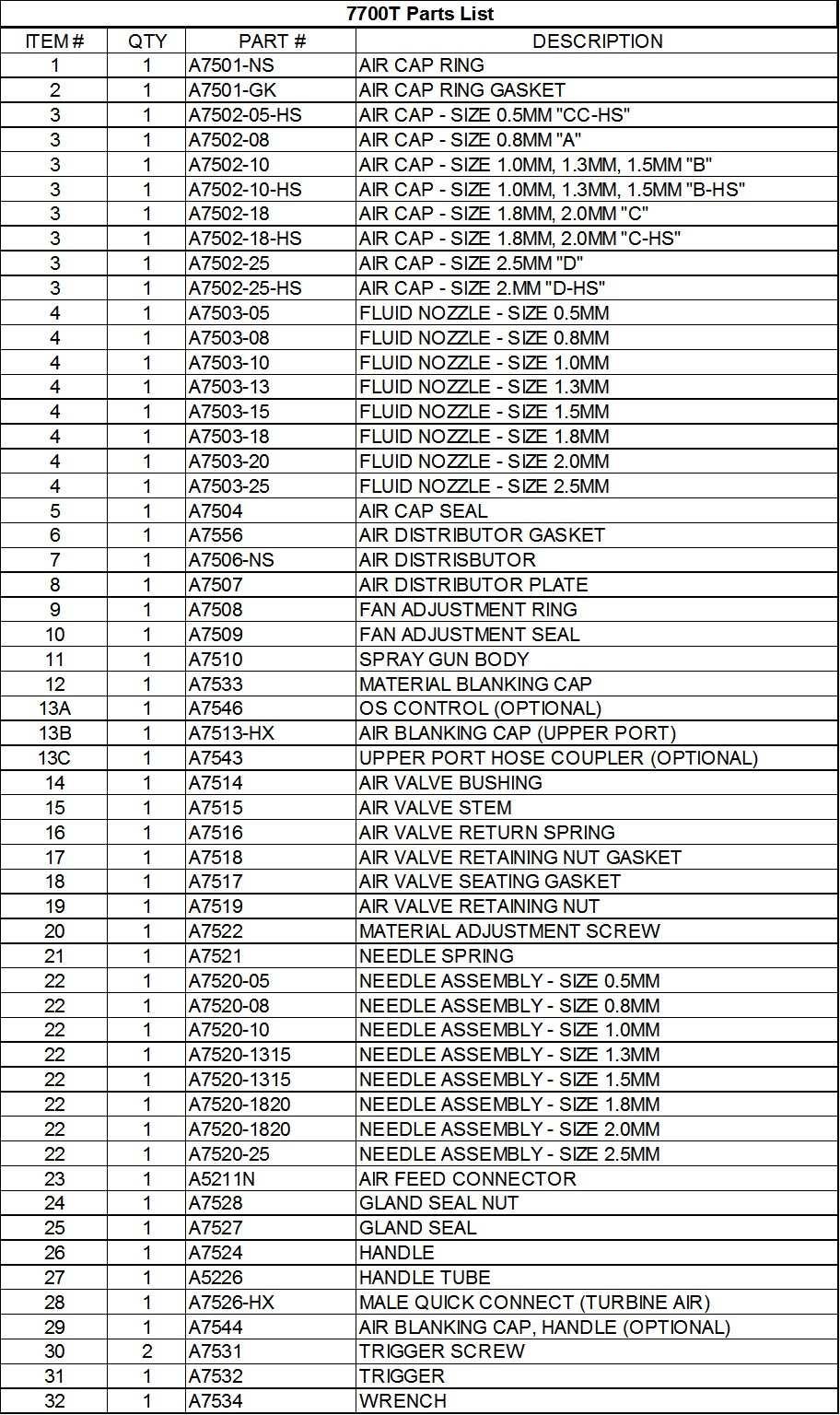
33 34
34 Model A Quart Cup Assembly Parts List Diagram # Part # Description 1 A5274 Center bolt/pick-up tube 2 A5276 Air Relief - Cap, Base & Gasket 2 A5276 Air Relief - Cap, Base & Gasket 3 A5271 Yoke 4 A5278 Lever 5 A5270 Cup top casting 6 A5280 Cup top gasket (White poly) 7 A4254 Material Filter 8 A5272 Cup top lock nut 9 A5324 Air Stem 10 A5299 Air Feed Tube 11 A5265 Non-return valve 12 A5275 Quick release cup
Apollo Sprayers HVLP. Instruction Manual 7500 Series A.. tom. Apollo Sprayers lnt'l., Inc Joshua Way Vista, CA
 Apollo Sprayers HVLP Instruction Manual 7500 Series A.. tom Apollo Sprayers lnt'l., Inc. 1040 Joshua Way Vista, CA 92081 760-727-8300 www.hvlp.com 1. Safety... 3 2. Introduction... 4 2.1 About Your New
Apollo Sprayers HVLP. Instruction Manual 7500 Series A.. tom. Apollo Sprayers lnt'l., Inc Joshua Way Vista, CA
 Apollo Sprayers HVLP Instruction Manual 7500 Series A.. tom Apollo Sprayers lnt'l., Inc. 1030 Joshua Way Vista, CA 92081 760-727-8300 www.hvlp.com 1. Safety... 3 2. Introduction... 4 2.1 About Your New
Instruction Manual. This manual contains important warnings and instructions. Please read these instructions carefully and keep for your reference.
 Instruction Manual This manual contains important warnings and instructions. Please read these instructions carefully and keep for your reference. 2014 Apollo Sprayers International, Inc. Table of Contents
ApolloSprayers POWER SERIES Turbine Instruction Manual
 ApolloSprayers POWER SERIES Turbine Instruction Manual Table of Contents 1 Safety... 3 2 TrueHVLP Spray Finishing Systems... 5 2.1 How Your HVLP Turbine System Works... 5 2.2 How Your Spray Gun Works...
Instruction Manual BY APOLLOSPRAYERS
 I-MISER 3 0 0 0 BY APOLLOSPRAYERS Instruction Manual This manual contains important warnings and instructions. Please read these instructions carefully and keep for your reference. 2015 Apollo Sprayers
ApolloSprayers PRECISION-5 Turbine Instruction Manual
 ApolloSprayers PRECISION-5 Turbine Instruction Manual Table of Contents 1 Safety... 3 2 TrueHVLP Spray Finishing Systems... 5 2.1 How Your HVLP Turbine System Works... 5 2.2 How Your Spray Gun Works...
ApolloSprayers Turbine Instruction Manual
 ApolloSprayers Turbine Instruction Manual 1 1. Safety... 3 2. TrueHVLP Spray Finishing Systems... 5 2.1 How Your HVLP Turbine System Works... 5 2.2 How Your Spray Gun Works... 5 2.3 Preparing To Use Your
INSTRUCTIONS. US Patent Pending HVLP Turbine Guns
 INSTRUCTIONS 309317 INSTRUCTIONS This manual contains important warnings and information. READ AND KEEP FOR REFERENCE. Rev. A US Patent Pending HVLP Turbine Guns 10 psi (0.07 MPa,.7 bar) Maximum Inlet
INSTRUCTION MANUAL (For Professional Use Only) T5020 MIST APPLICATOR
 T5020 MIST APPLICATOR") INSTRUCTION MANUAL (For Professional Use Only) T5020 MIST APPLICATOR DO NOT USE EQUIPMENT BEFORE READING THIS MANUAL This manual contains important warnings and instructions. Please read these instructions
INSTRUCTION MANUAL (For Professional Use Only) T5020 MIST APPLICATOR DO NOT USE EQUIPMENT BEFORE READING THIS MANUAL This manual contains important warnings and instructions. Please read these instructions
Thank you for purchasing a Campbell Hausfeld product. If you have any technical questions about this product, please call
 Please read and save these instructions. Read carefully before attempting to assemble, install, operate or maintain the product described. Protect yourself and others by observing all safety information.
D Instructions/Parts. Siphon Feed Detail Spray Gun D
 Instructions/Parts D-5-55 Siphon Feed Detail Spray Gun FOR PRODUCT INFORMATION CALL: 1-800-742-7731 309991D Important Safety Instructions Read all warnings and instructions in this manual. Save these instructions.
MGFHVLP. Instructions/Parts. Mini Gravity Feed System E. Part No Includes MGFHVLP Mini Gravity Feed Spray Gun and MGC 125 Gravity Cup.
 Instructions/Parts MGFHVLP Mini Gravity Feed System FOR PRODUCT INFORMATION CALL: 1-800-742-7731 309989E For gravity feed spraying of automotive colors and clears. Ideal for touch-up and detail work. Important
Owners Manual The Leading Manufacturer of HVLP Turbines, Spray Guns and Parts Since
 Owners Manual The Leading Manufacturer of HVLP Turbines, Spray Guns and Parts Since 1994 1 WARRANTY THIS NEW TURBINE UNIT AND SPRAY GUN ARE COMPLETELY COVERED UNDER WARRANTY AGAINST DEFECTS IN MATERIAL
.6 Liter (20 oz.) Touch Up Spray Gun 126-A
 Touch Up Spray Gun 126-A") .6 Liter (20 oz.) Touch Up Spray Gun 126-A Usage Instructions & Parts List www.fibreglast.com 1.800.821.3283 385 Carr Drive Brookville, OH 45309 Operating Instructions & Suggestions This is a heavy duty
.6 Liter (20 oz.) Touch Up Spray Gun 126-A Usage Instructions & Parts List www.fibreglast.com 1.800.821.3283 385 Carr Drive Brookville, OH 45309 Operating Instructions & Suggestions This is a heavy duty
5-STAGE ELECTRIC TURBINE
 Item #15334 5-STAGE ELECTRIC TURBINE HVLP PAINT SYSTEM INSTRUCTIONS SAFETY INFORMATION READ INSTRUCTIONS! Thoroughly read and understand this instruction manual before using. Save manual for future reference.
Electric Airless Sprayers Operating Instructions
 Electric Airless Sprayers Operating Instructions 309365 Rev. A 3000 psi (210 bar, 21 MPa) Maximum Working Pressure How To Perform: Component Identification....... 3 Setup........................... 4 Startup..........................
GRAVITY FEED SPRAY GUN & CUP SPECIFICATIONS. Operating Instructions Warning Information Parts Breakdown. Fluid Orifice mm. Air Inlet:...
 Operating Instructions Warning Information Parts Breakdown SPECIFICATIONS Fluid Orifice... 1.4mm Air Inlet:...1/4 NPT Rec. Max. Inlet Pressure:...50 PSI CFM:... 3.1 at 50 PSI Nozzle Pressure... 10 PSI
T1-Titanium Non-HVLP Spray Gun
 T1-Titanium Non-HVLP Spray Gun THE SPRAY GUN PEOPLE FOR PRODUCT INFORMATION CALL: 1-800-742-7731 Important Safety Instructions Read all warnings and instructions in this manual. Save these instructions.
ATD-6810 SPRAY GUN W/CUP INSTRUCTION MANUAL
 ATD-6810 SPRAY GUN W/CUP INSTRUCTION MANUAL Read this Instruction Manual carefully and understand it completely, basic precaution should be strictly followed to prevent the damage to the tool and injury
ATTENTION! READ BEFORE ATTACHING THE AIR HOSE
 Binks SV50 HVLP GRAVITY FEED SPRAY GUN & TOUCHUP GUN ATTENTION READ BEFORE ATTACHING THE AIR HOSE HVLP AIR SUPPLY REQUIREMENTS FULL SIZE GUN: 30 PSI inlet pressure provides 10 PSI at the air cap. Consumes
C.qrk 9/28/00 7:01 AM Page 1. NB Spray Guns. Owner s Manual Form No C 1999 Wagner Corporation-All rights reserved
 0276712C.qrk 9/28/00 7:01 AM Page 1 NB Spray Guns Owner s Manual 0900 Form No. 0276712C 1999 Wagner Corporation-All rights reserved 0276712C.qrk 9/28/00 7:01 AM Page 2 EXPLOSION HAZAD - Incompatible materials.
DISPLACEMENT PUMP INSTRUCTIONS-PARTS LIST Rev. K. Model , Series A Model , Series B Model , Series A
 INSTRUCTIONS-PARTS LIST INSTRUCTIONS This manual contains important warnings and information. READ AND KEEP FOR REFERENCE. DISPLACEMENT PUMP 308190 Rev. K 3000 psi (210 bar) MAXIMUM WORKING PRESSURE Model
Airless Spray Gun INSTRUCTIONS DP psi (345 bar) Maximum Working Pressure
 Maximum Working Pressure") INSTRUCTIONS DP-6376 Airless Spray Gun 5000 psi (345 bar) Maximum Working Pressure INSTRUCTIONS This manual contains important warnings and information. READ AND KEEP FOR REFERENCE. Table of Contents Warnings......................................
INSTRUCTIONS DP-6376 Airless Spray Gun 5000 psi (345 bar) Maximum Working Pressure INSTRUCTIONS This manual contains important warnings and information. READ AND KEEP FOR REFERENCE. Table of Contents Warnings......................................
Binks Model M1-G HVLP GRAVITY FEED SPRAY GUN
 Binks Model M1-G HVLP GRAVITY FEED SPRAY GUN The Binks M1-G HVLP Gravity Feed Gun is a high quality sprayer that produces fine finish for compliant and non-compliant areas. A superbly balanced forged aluminum
ATD PIECE HVLP SPRAY GUN SET INSTRUCTION MANUAL
 ATD-6904 6 PIECE HVLP SPRAY GUN SET INSTRUCTION MANUAL Read this manual carefully and understand it completely. Retain manual for future use. Always follow safety precautions to prevent personal injury
MicroCoat. System Operating Manual MC2000 Series. MC785, MC785-WF Spray Valves. US: UK: Mexico:
 MicroCoat System Operating Manual MC2 Series MC785, MC785-WF Spray Valves A NORDSON COMPANY US: 8-498-8865 UK: 8 585733 Mexico: 1-8-556-3484 Introduction The MicroCoat System provides precise lubrication
Binks Model 95 SPRAY GUN
 Binks Model 95 SPRAY GUN Model 95 Signature Series Spray Gun This handheld gun is the premier spray gun in the Binks line. A combination of the three best industrial spray guns, Model 95 sets a new standard.
ATD MM PRIMER GUN W/CUP INSTRUCTION MANUAL
 ATD-6902 1.8MM PRIMER GUN W/CUP INSTRUCTION MANUAL Read this manual carefully and understand it completely. Retain manual for future use. Always follow safety precautions to prevent personal injury and/or
H2O-C14 AAA FINE FINISH SERIES PUMP OUTFIT
 PRODUCT INFORMATION H2O-C14 AAA FINE FINISH SERIES PUMP OUTFIT The H2O-C14 AAA pump system is an air assisted airless unit which combines airless and conventional or HVLP air atomization technologies to
ATD MM TOUCH UP GUN W/CUP INSTRUCTION MANUAL
 ATD-6903 1.0MM TOUCH UP GUN W/CUP INSTRUCTION MANUAL Read this manual carefully and understand it completely. Retain manual for future use. Always follow safety precautions to prevent personal injury and/or
USE and MAINTENANCE INSTRUCTION MANUAL AZ3 HTE2 AZ3 HTE2 HVLP GRAVITY. SPRAY GUN Series. en it fr es pt de se
 USE and MAINTENANCE INSTRUCTION MANUAL AZ3 HTE2 AZ3 HTE2 HVLP GRAVITY SPRAY GUN Series en it fr es pt de se TECHNICAL DATA Technical AZ3 HTE2 AZ3 HTE2 HVLP 1.0 80 180 1.3 10-15HTE 140 200 240 1.5 2.0 160
MACH 1A HVLP (MACH 1AV HVLP) Automatic Airspray Gun
 Automatic Airspray Gun") MACH 1A HVLP (MACH 1AV HVLP) Automatic Airspray Gun Your new Binks MACH 1A HVLP Automatic Spray Gun is exceptionally rugged in construction, and is built to stand up under hard, continuous use. However,
MACH 1A HVLP (MACH 1AV HVLP) Automatic Airspray Gun Your new Binks MACH 1A HVLP Automatic Spray Gun is exceptionally rugged in construction, and is built to stand up under hard, continuous use. However,
Page 1 of 19. Part# /10/2006
 Part# 1002733-01 10/10/2006 This manual contains important information concerning the installation and operation of the gun washers listed above. Read manual thoroughly and keep for future reference INSTRUCTIONS
MicroCoat System Operating Manual MC4000 Series MC785M, MC785M-WF Spray Valves
 MicroCoat System Operating Manual MC Series MC785M, MC785M-WF Spray Valves A NORDSON COMPANY Introduction The MicroCoat System provides precise lubrication control for metal stamping operations. The MC
B14 AAA FINE FINISH SERIES PUMP OUTFIT
 PRODUCT INFORMATION B14 AAA FINE FINISH SERIES PUMP OUTFIT The B14 AAA pump system is an air assisted airless unit which combines airless and conventional or HVLP air atomization technologies to produce
NEW! NEW! Series 3100H HVLP AirSpray Gun HVLP 1 Qt. Cup Siphon Fed Guns Air Requirements: PSI
 High Transfer Efficiency AQMD Compliant Ultra-Fine Atomization Precision Fan Control Easy-Clean Gun Body Built-In Cheater Valve Series 3100H HVLP AirSpray Gun HVLP 1 Qt. Cup Siphon Fed Guns Air Requirements:
Model No. SP Low Volume Low Pressure (LVLP) Gravity Feed Spray Gun
 Gravity Feed Spray Gun") Model No. SP-33000 Low Volume Low Pressure (LVLP) Gravity Feed Spray Gun - 1 - TABLE OF CONTENTS: 1. Description 2. Specification and Technical Data 3. Important Safety Instruction 4. Instructions for
Model No. SP-33000 Low Volume Low Pressure (LVLP) Gravity Feed Spray Gun - 1 - TABLE OF CONTENTS: 1. Description 2. Specification and Technical Data 3. Important Safety Instruction 4. Instructions for
EP1306N 5 Gallon Can Extruder System Rev. A June EP1306N Operation Manual
 EP1306N Operation Manual 1 THIS PAGE HAS BEEN INTENTIONALLY LEFT BLANK 2 TABLE OF CONTENTS SECTION 1: SAFETY... 4 1. GENERAL SAFETY... 5 2. PUMP SAFETY... 5 3. FLUID PRESSURE AND COMPATIBILITY... 6 4.
Pro Gun (Model: UCpro and UCPro Plus)
") Undercoating/Rustproofing Pro Gun (Model: UCpro and UCPro Plus) Professional Undercoating and Rustproofing gun designed to apply protective coatings such as waterborne and solvent based under coatings,
Undercoating/Rustproofing Pro Gun (Model: UCpro and UCPro Plus) Professional Undercoating and Rustproofing gun designed to apply protective coatings such as waterborne and solvent based under coatings,
USE and MAINTENANCE INSTRUCTION MANUAL W-300 W-300 WB LPH-300 GRAVITY. SPRAY GUN Series. en it fr es pt de se
 USE and MAINTENANCE INSTRUCTION MANUAL W-300 W-300 WB LPH-300 GRAVITY SPRAY GUN Series en it fr es pt de se TECHNICAL DATA High T.E.C. series Nozzle_Needle set Combination W-300 WB W-300 W-300-081G 0.8
B14 AAA FINE FINISH SERIES PUMP OUTFIT
 PRODUCT INFORMATION B14 AAA FINE FINISH SERIES PUMP OUTFIT The B14 AAA pump system is an air assisted airless unit which combines airless and conventional or HVLP air atomization technologies to produce
Binks Model 95SL SPRAY GUN
 Binks 95SL spray gun is the latest innovation in the 95 model line of spray guns. The 95SL is slim and streamlined, and weighs less than other models. These features make this product the gun of choice
Model 95G Gravity Feed Spray Gun
 Model 95G Gravity Feed Spray Gun INTRODUCTION This unique spray gun is engineered with sprayer comfort, operating simplicity, and paint usage efficiency in mind. Ideal for automotive refinishing, test
AUTOMATIC AIRSPRAY GUN
 INSTRUCTION MANUAL AUTOMATIC AIRSPRAY GUN Manual : 0407 573.011.212 Date : 19/07/04 Supersede : KREMLIN REXSON - Site de Stains : 150, avenue de Stalingrad 93 245 - STAINS CEDEX - FRANCE Téléphone : 33
RAZOR. RAZOR HVLP Spray Guns
 RAZOR RAZOR HVLP Spray Guns Provides generous material flow that helps you get the job done quickly Offers exceptional atomization rate Promotes a superior finish Proven effective for clear coat, base
Model 95G Gravity Feed Spray Gun 6119-XXXX-X
 Model 95G Gravity Feed Spray Gun 6119-XXXX-X Introduction This unique spray gun is engineered with sprayer comfort, operating simplicity, and paint usage efficiency in mind. Ideal for automotive refinishing,
Gel Coat Cup Gun 120-A
 Gel Coat Cup Gun 120-A Usage Instructions & Parts List www.fibreglast.com 1.800.821.3283 385 Carr Drive Brookville, OH 45309 Operating Instructions & Suggestions Your model 120-A spray gun is quick and
Binks AIRLESS 1 SPRAY GUN
 Binks AIRLESS 1 SPRAY GUN (For Professional Use Only) Model 6700-0080-0 Less Tip OPERATION AND MAINTENANCE INSTRUCTIONS OPERATING INSTRUCTIONS: The following steps and recommendations should be followed
Fuji Spray LX 20 HVLP Compressor Spray Gun User Manual
 Fuji Spray LX 20 HVLP Compressor Spray Gun 6265G LX-20 Gravity 6260S LX-20 Pressure Feed User Manual Page 2 of 13 Contents Contents and Specifications... 1 Safety Precautions... 2 3 Assembly... 4 Operation...
Binks MACH 1SL HVLP SPRAY GUN Mach 1SLA (Adjustable Fluid Inlet) & Mach 1SLV (Vitreous)
 & Mach 1SLV (Vitreous)") Binks MACH 1SL HVLP SPRAY GUN Mach 1SLA (Adjustable Inlet) & Mach 1SLV (Vitreous) The Binks MACH 1SL HVLP Gun is a top quality high performance air spray gun. You only have to pick it up to feel the difference.
Binks MACH 1SL HVLP SPRAY GUN Mach 1SLA (Adjustable Inlet) & Mach 1SLV (Vitreous) The Binks MACH 1SL HVLP Gun is a top quality high performance air spray gun. You only have to pick it up to feel the difference.
Binks Cub SL HVLP TOUCH-UP and COATINGS SPRAY GUN
 Binks Cub SL HVLP TOUCH-UP and COATINGS SPRAY GUN Binks Mach 1 Cub SL HVLP Gun is the finest touch-up and specialty coatings gun available today. The gun has been ergonomically designed to give operators
Fast-Flo Pump INSTRUCTIONS-PARTS LIST. Table of Contents 1:1 RATIO
 INSTRUCTIONS-PARTS LIST INSTRUCTIONS This manual contains important warnings and information. READ AND KEEP FOR REFERENCE. First choice when quality counts. 07 7 Rev. Z Supersedes W Includes Rev. Y changes
Zip-Tex Spray Gun. Instructions A. Model psi (0.86 MPa, 8.6bar) Maximum Working Pressure
 Maximum Working Pressure") Instructions Zip-Tex Spray Gun 311159A - For water-based materials only - (Consult your material supplier for Warnings and Application Requirements) Model 249458 125 psi (0.86 MPa, 8.6bar) Maximum Working
Instructions Zip-Tex Spray Gun 311159A - For water-based materials only - (Consult your material supplier for Warnings and Application Requirements) Model 249458 125 psi (0.86 MPa, 8.6bar) Maximum Working
Corrosion Control Equipment and Supplies
 Distributed by: Corrosion Control Equipment and Supplies Houston Office: 248 McCarty Dr. Houston, TX 77029-1195 (713) 672-8251 Fax (713) 672-6636 1-800-CLEMTEX www.clemtex.com clemtex@clemtex.com Dallas
HVLP CONTRACTOR. Self-contained and easily portable fine-finish sprayers. PROVEN QUALITY. LEADING TECHNOLOGY.
 HVLP Self-contained and easily portable fine-finish sprayers. CONTRACTOR PROVEN QUALITY. LEADING TECHNOLOGY. HVLP-Turbine Gun Concentrate on applying the finish, not working the gun! Get superior results
Binks AIRLESS 1M SPRAY GUN
 Binks AIRLESS 1M SPRAY GUN (For Professional Use Only) Model 44-6000 OPERATION AND MAINTENANCE INSTRUCTIONS OPERATING INSTRUCTIONS: The following steps and recommendations should be followed to get the
MODEL NUMBER: BD-116C USER GUIDE
 Airbrush MODEL NUMBER: BD-116C USER GUIDE WEBSITE: EMAIL: www.airbrushheaven.co.uk enquiries@airbrushheaven.co.uk 1 YEAR WARRANTY Contents 1. Welcome Section 2. General Information & Safety Instructions
Operation Manual FLG-G5 Transtech Gravity Spray Gun SB-E ISS.05
 Operation Manual FLG-G5 Transtech Gravity Spray Gun SB-E-2-790 ISS.05 Operation Manual FLG5 Gravity-feed Spray Gun Important Read and follow all instructions and Safety Precautions before using this equipment
TS1251 PRESSURE DISPENSER USER'S MANUAL
 TS1251 PRESSURE DISPENSER USER'S MANUAL TABLE OF CONTENTS SECTION DESCRIPTION PAGE NUMBER 1.0 CAUTIONS AND WARNINGS... 3 2.0 INTRODUCTION... 4 3.0 DESCRIPTION... 4 & 5 4.0 SET UP AND INSTALLATION... 6
Spray Equipment for Every Purpose Industrial Selection Guide
 Spray Finishing Equipment Selection Guide A98-142R Spray Equipment for Every Purpose Industrial Selection Guide Choosing a Spray Outfit is as easy as 1 2 3! 1 Paint Usage Per Day Getting Paint to the Spray
Model 570 Automatic Mastic Airless Spray Gun
 Model 570 Automatic Mastic Airless Spray Gun 6700-0000-7 For Professional Use Only warning high pressure warning Maximum working Pressure Up to 4000 pounds per square inch Do not point spray gun at any
Maintenance Information
 51984144 Edition 6 May 2014 Air Paving Breaker MX60 & MX90 Maintenance Information Save These Instructions Product Safety Information WARNING Failure to observe the following warnings, and to avoid these
Instructions Parts List
 Instructions Parts List : RATIO Fast Flo Pump Air operated piston transfer pump for low viscosity fluids. For professional use only. Only models that are EX certified are approved for use in European explosive
Binks Cub SL HVLP TOUCH-UP and COATINGS SPRAY GUN
 Binks Mach 1 Cub SL HVLP Gun is the finest touch-up and specialty coatings gun available today. The gun has been ergonomically designed to give operators superb control and comfort over a range of uses.
Model 550 Automatic Airless Spray Gun
 Model 550 Automatic Airless Spray Gun For Professional Use Only warning high pressure warning Maximum Working pressure Up to 3000 pounds per square inch Do not point spray gun at any part of the human
LG-60-3PT-WP-309-BL-TSC
 55 Model No: LG-0-PT-WP-0-BL-TSC 0 Gallon Point Lawn & Garden Sprayer W/Pump & Coupler & Boomless Boom Assembly / Operation Instructions / Parts ASSEMBLY Most of the sprayer has been assembled at the factory..
Illustration Key 1. Fluid Inlet, 1/4 NPS(m) 2. Air Nozzle 3. Retaining Ring 4. Fan Control 5. Fluid Control Knob 6. Gun Body 7. Air Inlet 1/4 NPS(m)
 2. Air Nozzle 3. Retaining Ring 4. Fan Control 5. Fluid Control Knob 6. Gun Body 7. Air Inlet 1/4 NPS(m)") Binks Mach 1 Cub SL HVLP Gun is the finest touch-up and specialty coatings gun available today. The gun has been ergonomically designed to give operators superb control and comfort over a range of uses.
Binks Mach 1 Cub SL HVLP Gun is the finest touch-up and specialty coatings gun available today. The gun has been ergonomically designed to give operators superb control and comfort over a range of uses.
AIR COMPRESSOR OPERATING INSTRUCTION AND PARTS LIST
 AIR COMPRESSOR OPERATING INSTRUCTION AND PARTS LIST BELT TYPE IMPORTANT PLEASE MAKE CERTAIN THAT THE PERSON WHO IS TO USE THIS EQUIPMENT CAREFULLY READS AND UNDERSTANDS THESE INSTRUCTIONS BEFORE STARTING
Brake System H TX, H2.0TXS [B475]; H TX [B466] Safety Precautions Maintenance and Repair
![Brake System H TX, H2.0TXS [B475]; H TX [B466] Safety Precautions Maintenance and Repair](/thumbs/86/93834005.jpg "Brake System H TX, H2.0TXS [B475]; H TX [B466] Safety Precautions Maintenance and Repair") HMM180001 Brake System H1.5-1.8TX, H2.0TXS [B475]; H2.5-3.5TX [B466] Safety Precautions Maintenance and Repair When lifting parts or assemblies, make sure all slings, chains, or cables are correctly fastened,
HMM180001 Brake System H1.5-1.8TX, H2.0TXS [B475]; H2.5-3.5TX [B466] Safety Precautions Maintenance and Repair When lifting parts or assemblies, make sure all slings, chains, or cables are correctly fastened,
Backpack Sprayer. Use and Care Manual
 Backpack Sprayer Use and Care Manual BACKPACK SPRAYER CAUTION: Read and follow all instructions Do Not Return This Backpack To The Store For Help, Information or Parts, Call : 1-800-311-9903 The Fountainhead
Binks Model 2001 AND 2001V SPRAY GUNS
 Binks Model 2001 AND 2001V SPRAY GUNS 1 2 3 4 Your new Binks spray gun is exceptionally rugged in construction, and is built to stand up under hard, continuous use. However, like any other fine precision
SPEEFLO. PowrTex 300dd / 600dd Texture Sprayers. Owner s Manual For professional use only. Do not use this equipment before reading this manual!
 Owner s Manual For professional use only Do not use this equipment before reading this manual! SPEEFLO PowrTex 300dd / 600dd Texture Sprayers These sprayers are for use with water-based materials only!
MACH 1A HVLP (MACH 1AV HVLP) Automatic Airspray Gun
 Automatic Airspray Gun") MACH 1A HVLP (MACH 1AV HVLP) Automatic Airspray Gun Your new Binks MACH 1A HVLP Automatic Spray Gun is exceptionally rugged in construction, and is built to stand up under hard, continuous use. However,
MACH 1A HVLP (MACH 1AV HVLP) Automatic Airspray Gun Your new Binks MACH 1A HVLP Automatic Spray Gun is exceptionally rugged in construction, and is built to stand up under hard, continuous use. However,
QUALSPRAY 1 QUART PRESSURIZED CUPS Copyright , Homestead Finishing Products. All rights reserved
 QUALSPRAY 1 QUART PRESSURIZED CUPS Copyright 2003-2006, Homestead Finishing Products. All rights reserved Thank you for your purchase of the QualSpray QS-32 1 quart pressurized cup. With proper care and
METAL BLACKENING SYSTEM
 Item #15357 METAL BLACKENING SYSTEM INSTRUCTIONS The Eastwood Metal Blackening System replicates the factory Black Oxide coating found on many automotive bolts and fasteners as well as numerous small parts.
Binks MACH 1SL HVLP Spray Gun 7000-XXXX-X
 Binks MACH 1SL HVLP Spray Gun 7000-XXXX-X Mach 1SLA (7001-XXXX-X) The Binks MACH 1SL HVLP Gun is a top quality high performance air spray gun. You only have to pick it up to feel the difference. Its superbly
LINE PAINT SPRAY GUN VERFPISTOOL INSTRUCTION MANUAL HANDLEIDING FAT-0111 FAT-0111 EN NL. Zhong Nan Trading CO., Gompertsstraat nr.
 Operation manual and security instructions inside the box. Use safety glasses. Keep this tool away from children. Ford Motor Company trademarks and trade dress used under license to Nine HKG, Ltd. fordmotorcompany.com
Page 1 of 12. Part# /30/2016
 Part# 1007480-02 9/30/2016 This manual contains important information concerning the installation and operation of the gun washers listed above. Read manual thoroughly and keep for future reference. INSTRUCTIONS
OPERATOR S MANUAL PROFESSIONAL CONTRACTOR PRODUCTS. Model 1240 Model 1260 Model 2260
 2719 Lake City Way, Burnaby, BC, V5A 2Z6? P.O. Box 75, Custer WA 98240-0052? Phone: (604) 420-6543 Fax: (604) 420-8725 OPERATOR S MANUAL Model 1240 Model 1260 Model 2260 PROFESSIONAL CONTRACTOR PRODUCTS
DIRECT-DRIVE PRESSURE WASHERS
 DIRECT-DRIVE PRESSURE WASHERS PJG SERIES PRESSURE WASHER MANUFACTURED BY: PJG-2001 PJG-2501-6.5 PJG-2501 PJG-3000 PJG-3001 PJG-3501 PJG-4001 OPERATOR s INTRODUCTION Thank you for purchasing a Mancorp Pressure
2-1/4 Gallon Sprayer
 2-/4 Gallon Sprayer 94008 ASSEMBLY AND OPERATING INSTRUCTIONS 349 Mission Oaks Blvd., Camarillo, CA 930 Visit our Web site at http://www.harborfreight.com Copyright 2005 by Harbor Freight Tools. All rights
BINKS MODEL 460 LIGHTWEIGHT AUTOMATIC SPRAY GUN
 SERVICE MANUAL EN BINKS MODEL 460 LIGHTWEIGHT AUTOMATIC SPRAY GUN AIR FLOW ADJUSTMENT Clockwise to reduce pressure; Counterclockwise to increase pressure. 1/2" DIA. MOUNTING HOLE FLUID NEEDLE ADJUSTMENT
MODEL NUMBER: BD-132 USER GUIDE
 Airbrush MODEL NUMBER: BD-132 USER GUIDE WEBSITE: EMAIL: www.airbrushheaven.co.uk enquiries@airbrushheaven.co.uk 1 YEAR WARRANTY Contents 1. Welcome Section 2. General Information & Safety Instructions
GX-7A, GX-7 DI, and GX Spray Guns
 Operation, Parts, Service, Repair GX-7A, GX-7 DI, and GX-7 400 Spray Guns 311321M EN For use with non-flammable polyurethane foams, two-component coating systems (polyureas), and some two-component epoxy
Troubleshooting Guide for Pumps ATD ATD ATD5289
 PROBLEM: Your pump does not work? There are Three Basic Problems! Troubleshooting Guide for Pumps ATD5217 - ATD5219 - ATD5289 Air Motor Operates but nothing comes out. This is the most common problem.
Heavy Duty Sprayer Owners Manual Model MS-O
 Heavy Duty Sprayer Owners Manual Model MS-O Table of Contents Warranty 4 Warning 5 Assembly and Preparation 6 Operation 7 Cleaning and Storage 7 Standard Spray Gun & Parts List 8 Trigger Style Spray Gun
Operating manual GA 250AL GA 400AL. Edition 07 / Automatic Airless Spraygun. II 2GX (Atex 95)
") Operating manual GA 250AL GA 400AL Edition 07 / 2005 Automatic Airless Spraygun II 2GX (Atex 95) Contents 1 ABOUT THESE INSTRUCTIONS 5 1.1 Languages 5 1.2 Warnings, notes and symbols in these instructions
Operating manual GA 250AL GA 400AL Edition 07 / 2005 Automatic Airless Spraygun II 2GX (Atex 95) Contents 1 ABOUT THESE INSTRUCTIONS 5 1.1 Languages 5 1.2 Warnings, notes and symbols in these instructions
SB ISS.04. Operation Manual AGMDPRO Automatic Spray Gun
 EN SB-2-991 ISS.04 Operation Manual AGMDPRO Automatic Spray Gun Table of Contents Topic Page Specification and Materials of Construction 3 EC Declaration of Conformity 3 Safety Precautions 4 Model Part
PRODUCT OPERATING MANUAL
 PRODUCT OPERATING MANUAL PANBLAST TM CS37 SUCTION BLAST CABINET Manual Number: ZVP PC 0069 00 SECTION 1. GENERAL INFORMATION 2. ASSEMBLY & INSTALLATION INSTRUCTIONS 3. OPERATING INSTRUCTIONS 4. MAINTENANCE
AA1500 AIR-ASSISTED AIRLESS SPRAY GUN (WITH AA10 AIR AIR CAP AND FAN SIZE ADJUSTMENT FEATURE)
") AA1500 AIR-ASSISTED AIRLESS SPRAY GUN (WITH AA10 AIR AIR CAP AND FAN SIZE ADJUSTMENT FEATURE) The following instructions provide the necessary information for the proper operation and preventive maintenance
AA1500 AIR-ASSISTED AIRLESS SPRAY GUN (WITH AA10 AIR AIR CAP AND FAN SIZE ADJUSTMENT FEATURE) The following instructions provide the necessary information for the proper operation and preventive maintenance
CT0866 ORIGINAL INSTRUCTIONS SAVE
 600ML SPRAY GUN CT0866 ORIGINAL INSTRUCTIONS Cannon Tools Limited Address: 20 Station Road, Rowley Regis, West Midlands, B65 0JU.U.K. SAVE THESE INSTRUCTIONS AND PRECAUTIONS. READ ALL PRECAUTONS AND INSTRUCTIONS
Cylinder and Valve: AirHawk II Air Mask
 Cylinder and Valve: AirHawk II Air Mask MAINTENANCE AND REPAIR MSA 011 (L) Rev. 0 MSA 2010 Prnt. Spec. 10000005389(I) Mat. 10104218 Doc. 10104218 Parts List Cylinder Replacement Kits Item P/N Description
WARNING Carefully Read These Instructions Before Use
 DO NOT RETURN THIS SPRAYER TO STORE Call: 1-800-950-4458 Backpack Sprayer Use and Care Manual Manufactured for Northern Tool + Equipment Co., Inc. WARNING Carefully Read These Instructions Before Use Model
OWNER S MANUAL. Model: TR-40-GAS ( ) (40 Gallon Lawn & Garden Trailer Sprayer w/5-nozzle Boom Assembly) Technical Specifications
 (40 Gallon Lawn & Garden Trailer Sprayer w/5-nozzle Boom Assembly) Technical Specifications") OWNER S MANUAL Model: TR-40-GAS (5301339) (40 Gallon Lawn & Garden Trailer Sprayer w/5-nozzle Boom Assembly) Technical Specifications 40 Gal. Corrosion-Resistant Polyethylene Tank 5.5 HP Briggs & Stratton
OWNER S MANUAL Model: TR-40-GAS (5301339) (40 Gallon Lawn & Garden Trailer Sprayer w/5-nozzle Boom Assembly) Technical Specifications 40 Gal. Corrosion-Resistant Polyethylene Tank 5.5 HP Briggs & Stratton
36-1 DP PLEASE READ BEFORE USING THIS EQUIPMENT
 36-1 DP PLEASE READ BEFORE USING THIS EQUIPMENT DP 36-1 Assembly Instructions PLEASE READ INSTRUCTIONS COMPLETELY BEFORE STARTING We thank you for purchasing the DP-36 pressure system. This system has
Installation & Operation Manual. IMPORTANT: This manual contains important information. READ AND KEEP FOR REFERENCE.
 Elecronic Preset Meter 2 Industrial Handheld Series Model EPM2-IND Standard Series IMPORTANT: This manual contains important information. READ AND KEEP FOR REFERENCE. IOM-139-02-EN (1-12) 53400-139 Rev.
SPECIFICATIONS Horsepower: 1.5 HP Running Maximum PSI: 125 PSI Tank Capacity: 15 Gallons CFM: 6 40 PSI 5 90 PSI
 15 GALLON AIR COMPRESSOR Model: 7678 DO NOT RETURN TO STORE Please call 800-348-5004 for parts and service CALIFORNIA PROPOSITION 65 WARNING: You can create dust when you cut, sand, drill or grind materials
TWO-STAGE HYDRAULIC PUMP. RWP55-IBT-Air
 ORIGINAL INSTRUCTIONS Form No.1000458 5 SPX Corporation 5885 11th Street Rockford, IL 61109-3699 USA Tech. Services: (800) 477-8326 Fax: (800) 765-8326 Order Entry: (800) 541-1418 Fax: (800) 288-7031 Internet
SERIES OPERATION AND MAINTENANCE MANUAL
 SERIES OPERATION AND MAINTENANCE MANUAL This manual CONTAINS IMPORTANT WARNINGS, S and OTHER INSTRUCTIONS. Read and understand the instruction manual Carefully, before use and retain it for reference.
Model PRO 3500hc Electrostatic Air Spray Gun 65 kv, HIGH CONDUCTIVITY, MANUAL GUN
 INSTRUCTIONS-PARTS LIST This manual contains important warnings and information. READ AND KEEP FOR REFERENCE. 308018 Rev. W INSTRUCTIONS Model PRO 3500hc Electrostatic Air Spray Gun 65 kv, HIGH CONDUCTIVITY,