(12) INTERNATIONAL APPLICATION PUBLISHED UNDER THE PATENT COOPERATION TREATY (PCT)
|
|
|
- Laurence Day
- 5 years ago
- Views:
Transcription
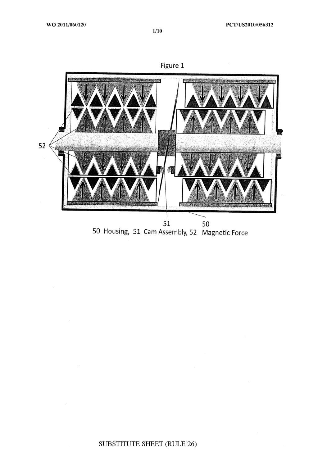
1 (12) INTERNATIONAL APPLICATION PUBLISHED UNDER THE PATENT COOPERATION TREATY (PCT) (19) World Intellectual Property Organization International Bureau (10) International Publication Number (43) International Publication Date t 19 May 2011 ( ) WO 201 1/ Al (51) International Patent Classification: (81) Designated States (unless otherwise indicated, for every H02K 49/10 ( ) kind of national protection available): AE, AG, AL, AM, AO, AT, AU, AZ, BA, BB, BG, BH, BR, BW, BY, BZ, (21) International Application Number: CA, CH, CL, CN, CO, CR, CU, CZ, DE, DK, DM, DO, PCT/US2010/ DZ, EC, EE, EG, ES, FI, GB, GD, GE, GH, GM, GT, (22) International Filing Date: HN, HR, HU, ID, JL, IN, IS, JP, KE, KG, KM, KN, KP, 11 November 2010 ( ) KR, KZ, LA, LC, LK, LR, LS, LT, LU, LY, MA, MD, (25) Filing Language: English ME, MG, MK, MN, MW, MX, MY, MZ, NA, NG, NI, NO, NZ, OM, PE, PG, PH, PL, PT, RO, RS, RU, SC, SD, (26) Publication Langi English SE, SG, SK, SL, SM, ST, SV, SY, TH, TJ, TM, TN, TR, TT, TZ, UA, UG, US, UZ, VC, VN, ZA, ZM, ZW. (30) Priority Data: 61/261, November 2009 ( ) US (84) Designated States (unless otherwise indicated, for every 12/943, November 2010 ( ) US kind of regional protection available): ARIPO (BW, GH, GM, KE, LR, LS, MW, MZ, NA, SD, SL, SZ, TZ, UG, (71) Applicant (for all designated States except US): AP ZM, ZW), Eurasian (AM, AZ, BY, KG, KZ, MD, RU, TJ, PLIED MAGNETICS RESEARCH, INC. [US/US]; TM), European (AL, AT, BE, BG, CH, CY, CZ, DE, DK, 3320 Jewel Cave Drive, Las Vegas, NV (US). EE, ES, FI, FR, GB, GR, HR, HU, IE, IS, IT, LT, LU, LV, MC, MK, MT, NL, NO, PL, PT, RO, RS, SE, SI, SK, (72) Inventors; and SM, TR), OAPI (BF, BJ, CF, CG, CI, CM, GA, GN, GQ, (75) Inventors/Applicants (for US only): TAYLOR, Junior, GW, ML, MR, NE, SN, TD, TG). Franklin [US/US]; 3320 Jewel Cave Drive, Las Vegas, NV (US). NEYWICK, Kenneth, Everett Published: [US/US]; 3320 Jewel Cave Drive, Las Vegas, NV (US). DWYER, Patrick, Earl [US/US]; 3320 Jewel with international search report (Art. 21(3)) Cave Drive, Las Vegas, NV (US). (74) Agent: MOY, Jeffrey, D.; Weiss & Moy, P.C., 4204 N. Brown Avenue, Scottsdale, AZ (US). (54) Title: ISOLATION TIMING MAGNETIC MOTOR Figure o 50 Housing, 51 Cam Assembly, 52 Magnetic Force o (57) Abstract: A magnetic motor has a shaft. An upper magnet is attached to the shaft and positioned around an upper perimeter of the shaft. A lower magnet is positioned around a lower perimeter of the shaft. A plurality of grooves is formed in the upper magnet and the lower magnet. Field diversion bands are positioned within the plurality of grooves.
2 ISOLATION TIMING MAGNETIC MOTOR AND METHOD RELATED APPLICATIONS [0001] The present patent application is related to and claims the benefit o f U.S. Provisional Application entitled, "Isolation and Timing Magnetic Motor", filed November 13, 2009, having U.S. Serial No. 61/261, 206, in the name o f the same inventors, and which is incorporated herein by reference in its entirety. BACKGROUND [0002] Embodiments o f this disclosure relate generally to motors, and, more specifically, to a magnetic motor that creates a new paradigm in how energy is produced. The intent o f this design i s to create a functional magnetic motor with significant torque and to can b e self starting. [0003] Magnets and magnetism, including electromagnetism, have been incorporated and used historically in an assortment o f designs. A review o f the "prior art"
3 reveals distinct and different designs separate from this invention. Functionality and efficiency is lacking in some form or fashion in every instance, particularly in areas related to the facilitation of production of torque force, the methods of control of the torque forces produced including directionality, and the maintenance of the torque force produced and resultant usable Kinetic Energy. [0004] U. S. Patent No. 6,433,452B1 issued to Graham, discloses a magnetic motor wherein rotation of an output shaft i s achieved by means of a cam wheel which i s interconnected to the output shaft and an associated power rod operatively associated therewith with a magnet attached to the power rod. Multiple magnets are affixed to the outer periphery of a balance wheel which is interconnected to the output shaft. Linear movement of the magnet mounted on the power rod together with intermittent attractive or repulsive forces between magnet mounted on the power rod and multiple magnets mounted on the balance wheel provides continuous rotation to the output shaft. [0005] U. S. Patent No. 5,753,990 issued to Flynn et al., discloses a device for converting magnetic to mechanical force. The device has a member having an axis about which it i s rotatable, the member having a peripheral edge portion formed of a material that i s affected b y the presence of a magnetic force adjacent thereto. A t least one magnetic member is positioned
4 adjacent the peripheral portion of the rotatable member to produce a magnetic coupling force there between. The peripheral portion of the rotatable member has a shape such that the magnetic coupling between the magnetic member and the peripheral portion of the rotatable member varies continuously a s the rotatable member rotates. [0006]. S. Patent No. 4,598,221 issued to Lawson et al., discloses a self -starting rotational motor that uses a magnetic propelling force. The motor is based on the principle of maintaining interacting substantially perpendicular rotor and stator magnet flux field one within the other without gaps or spacing around the entire circumference of the magnet stator. The rotor magnets are controlled and moved relative to the stator magnets by a mechanism whereby the perpendicular rotor and stator magnet flux fields are maintained constantly in interacting relationship to produce turning of the rotor in one direction. [0007] U. S. Patent No. 4,196,365 issued to Presley, discloses a permanent magnet motor comprising a rotating shaft and a rotating magnet coupled to rotate with the shaft and sweeping a disc-like area a s the shaft rotates. A reciprocating magnet aligned to repel the rotary magnet is positioned adjacent to the area swept by the rotating magnet. Means coupled to the reciprocating magnet i s provided to forcefully displace the
5 reciprocating magnet toward the rotating magnet a s the rotating magnet is passing a top dead center position and for displacing the reciprocating magnet away from the rotating magnet after the rotating magnet has passed the bottom dead center position. [0008] The first design forces a magnet in and out of the magnetic field. Our design moves a magnet through the field and uses diversion techniques to move the field out o f the way when the field could hamper rotation of the armature. [0009] Some o f these designs have a rotating center that is extremely different from the present invention. In one case the design does not contain magnets in the rotating portion. Further the rotating disk changes mass a s a function of the degrees o f rotation or changes radius a s a function o f degrees o f rotation. Neither of these takes place in the present invention having a rotating shuttle armature. [0010] Other designs deal with perpendicular fields and rotating or rocking a magnet inside a field. The present invention works with parallel fields and the magnets are moving through the field. The present invention use shields to divert the magnetic fields when the magnets need to rotate through the opposing rotational fields. [0011] Finally another design contains a rotating disk with magnets incorporated on the face of the disk. The present application utilizes magnets that make up a rotating armature.
6 This design also incorporates a long bar that toggles back and forth with the use o f a solenoid that is timed off of a cam. Our design has no such toggling bar. [0012] Therefore, it would be desirable to provide a system and method that overcomes the above. SUMMARY [0013] In accordance with one embodiment, a magnetic motor has a shaft. A n upper magnet i s attached to the shaft and positioned around an upper perimeter o f the shaft. A lower magnet i s positioned around a lower perimeter o f the shaft. A plurality of grooves i s formed in the upper magnet and the lower magnet. Field diversion bands are positioned within the plurality of grooves. [0014] The features, functions, and advantages can be achieved independently in various embodiments o f the disclosure o r may be combined in yet other embodiments. DRAWINGS [0015] Embodiments of the disclosure will become more fully understood from the detailed description and the accompanying drawings, wherein: [0016] FIG 1 is a cross-sectional view of the magnetic motor perpendicular to shaft rotation.
7 [0017] FIG 2A i s a cross-sectional view of the stationary field assembly parallel to the shaft. [0018] FIG 2B i s a cross-sectional view of the stationary field assembly perpendicular to the shaft. [0019] FIG 3A is a cross-sectional view o f the shuttle armature assembly parallel to the shaft. [0020] FIG 3B is a cross-sectional view o f the shuttle armature assembly perpendicular to the shaft. [0021] FIG 4Ά is a cross-sectional view o f the shuttle armature inside the stationary field assembly parallel to the shaft. [0022] FIG 4B is a cross-sectional view o f the shuttle armature inside the stationary field assembly perpendicular to the shaft. [0023] FIG 5Ά is a cross-sectional view o f the magnet motor assembly perpendicular to the shaft with diversion bands aligned and magnets aligned. [0024] FIG 5B is a cross-sectional view of the magnet motor assembly perpendicular to the shaft with diversion rings aligned to center o f magnet positions. [0025] FIG A shows two magnetic motors mounted to the same shaft with a cam between them. In this orientation the two motors are 180 degree out of sync with each other.
8 [0026] FIG 6B shows the same assembly a s FIG A after shaft rotates 180 degrees. [0027] FIG 7Ά shows the inner and outer arc magnets. [0028] FIG 7B shows a cross-section of the inner and outer arc magnets. [0029] FIG 8A to FIG 8G shows different positions the shuttle armature achieves a s it rotates in a cross-sectional view perpendicular to the axis o f rotation. [0030] FIG 8A' to FIG 8G' shows different positions the shuttle armature achieves a s it rotates in a cross-sectional view parallel to the axis of rotation. DETAILED DESCRIPTION [0031] In the Figures, the following reference numbers be used [0032] 2 0 Mild steel tubing [0033] 2 1 Arc magnets [0034] 2 2 Field diversion bands [0035] 2 3 Gap between top and bottom magnets [0036] 2 4 Non ferrous bonding compound [0037] 3 0 Mild steel tube shaft [0038] 3 1 Arc magnets [0039] 32 Field diversion rings [0040] 33 Gap between magnets
9 [0041] 3 4 Non ferrous bonding compound [0042] 3 5 Bearings [0043] 40 Shuttle armature assembly [0044] 4 1 Stationary field assembly [0045] 42 Gap between shuttle armature assembly and stationary field assembly [0046] 5 0 Housing [0047] 5 1 Cam assembly [0048] 0 outer arc magnet [0049] 61 inner arc magnet [0050] The present invention for a magnetic motor will produce shaft power that can be connected to any thing that needs to move or produce power. The key to this product line is the use of plates or rings to divert the magnetic fields when the field interferes with producing rotation. Sliding a diversion ring or plate perpendicular to a magnetic field takes very little energy as compared to pulling a magnet or plate in and out of a field. Further we can control the speed and torque of rotation by controlling the amount of diversion allowed by controlling the distance the shuttle armature is allowed to travel [0051] FIG 1 shows two magnetic motors in a completed assembly. The second assembly is aligned 180 degrees of rotation away from the first assembly. There is a cam (51) (in
10 this design it is situated between the two motors) which i s used to cause the armature to shuttle back and forth as it rotates. The magnet force (52) is shown aligned in the left motor and blocked by the diversion rings on the right motor. [0052] FIG 2A shows two arc magnets (21) mounted on opposite sides o f the inside of a steel tube (20). Fig 2A also shows the diversion rings (22) mounted in the groves of the arc magnets but going all the way around. There is a gap (23) between the two arc magnets. [0053] FIG 2B i s a cross section view of Fig 2A. This figure shows how the arc magnets (21) are grooved. It also shows the placement of the diversion rings (22) in the groves of the arc magnets (21). The arc magnets (21) are secured to the inside of the steel tube (20). A non ferrous bonding material (24) is used to affix the rings (22) inside the groves but not touching the magnets. [0054] FIG 3A shows two arc magnets (31) mounted on opposite sides of the shaft (30). Fig 3A also shows the diversion rings (32) mounted in the groves o f the arc magnets (31) but going all the way around. Between the two arc magnets is a small gap (33). [0055] FIG 3B i s a cross section view o f Fig 3A. This figure shows how the arc magnets (31) are grooved. It shows the placement of the diversion rings (32) in the groves of the arc
11 magnets (31). The arc magnets are secured to the shaft (30). A non ferrous bonding material (34) is used to affix the rings (32) inside the groves but not touching the magnets. Fig 3B also shows bearings (35) on the shaft to allow it to rotate and shuttle. [0056] FIG 4A shows the shuttle armature (40) placed inside the stationary field assembly (41) with a small gap (42) between the two all the way around. [0057] FIG 4B is a cross-sectional view showing the shuttle armature (40) inside the stationary field assembly (41) with bearings (35) on the ends of the shuttle armature allowing it to rotate inside the stationary field assembly (41) and to shift in and out of the stationary field assembly (41). [0058] FIG 5A shows the diversion rings (22 and 32) aligned in the inner (40) to the outer (41) assemblies. The diversion rings (22 and 32) are aligned to allow the magnetic fields to interact a s shown in Fig 1 on the left side. [0059] FIG 5B shows the diversion rings (22 and 32) aligned to the arc magnet points between the inner (40) and outer (41) assemblies. The diversion rings (22 and 32) are aligned to divert the magnetic fields and prevent them from interacting as shown in Fig 1 on the right side. [0060] FIG 6A shows the alignment o f two motor assemblies on the same shaft 30. One is mounted 180 degrees of
12 rotation away from the other. This shows how multiple motors can be aligned to produce torque in different relative angles of rotation. This allows for more continuous torque along a single shaft 30. [0061] FIG 6B shows the armature after it rotates 180 degrees from its position in Fig 6A. This shows how the interaction between magnets 3 1 in the first half of the paired motors goes from a torque position to a non torque position, while the right side moves from a non torque state to a torque state, thus providing torque for a greater duration of rotation around the shaft 30. [0062] FIG 7A shows the inner (61) and outer (60) arc magnets. These figures give what appears to be a better shape o f magnet to use than the bar magnets 3 0 in the previous embodiments. [0063] FIG 7B shows the groves through a cross-section of the inner (61) and outer (60) arc magnets. This view shows how the points and groves are made into the arc magnets. [0064] FIG 8A to FIG 8G shows different positions the shuttle armature achieves a s it rotates in a cross-sectional view perpendicular to the axis of rotation. This sequence of figures steps through one full rotation of the shuttle armature. It shows how the shuttle armature magnets change their orientation in relation to the outer field assembly magnets.
13 [0065] FIG 8Α' to FIG 8G' shows different positions the shuttle armature achieves a s it rotates in a cross-sectional view parallel to the axis of rotation. This sequence of figures steps through one full rotation of the shuttle armature. It shows how the shuttle armature moves in and out o f the outer field assembly. A s it moves in and out the relative position of the diversion rings in the armature and the outer assembly i s changed. Figures 8A to 8G correlate to 8A' to 8G'. [0066] A single motor unit consists o f a stationary field assembly, a shuttle armature, a pair of end plates with shuttle cams, a torque shaft and enclosing housing. The stationary field assembly is contained in a mild steel tubing which acts also a s a magnetic circuit to divert all outward magnetic force (from centerline) of the arc magnets bonded inside and bonded to the inner arc surfaces are bands of mild steel for magnetic diversion (of inward). The shuttle armature consists of a pair of arc magnets bonded and banded to a mild steel tube at the ends of are support bushings that have the cam followers and fastenings to the torque shaft which passes through the end plates. During rotation of the torque shaft the rear end plate cam is timed to shuttle the armature to the front and the front end plate cam is timed to shuttle the armature to the rear. During the 160 degrees torque effort the armature diversion bands and the field diversion bands exposes the
14 magnetic fields. During the 180 degrees of free wheel the shuttle is aligned to divert all field/armature magnetic fields. The Stationary Field Assembly can be rotated 180 degrees for reversal o f shaft rotation and power control. OPERATION [0067] This design can be made to be self starting b y inserting the armature in the beginning pull position and from there it will continue to spin. Inserting the armature in the neutral position will keep the motor from starting until an external force i s added to rotate the shaft 180 degrees and from there it will b e self powered. [0068] The cam design and operation is not detailed in this application a s it can be completed in so many different ways. There are numerous mechanical and electronic systems that can be used to manage the amount of shuttling the armature performs. In successive designs there will be more detail which includes speed and torque management. These designs will vary with the type o f device the motor is installed in and the needs of the device. The operation and timing of the cam is important a s the synchronization with the magnetic field and the rings diverting the fields can b e used to manage the performance and direction of the motor.
15 [0069] Basic operation begins a s the diversions rings are shuttled back and forth to expose the attractive or opposing magnetic fields to each other allowing them to pull each other together or push each other apart. A s depicted in the figure sequence 8A to 8C. The diversion rings are moved back to a position diverting the fields as the armature rotates blocking the attractive or opposing force. A s depicted in figure sequence 8D to 8G. This allows the armature to free rotate without the magnetic fields trying to reverse the forward rotation. The cycle repeats allowing the motor to continue to operate producing usable shaft power. [0070] This technology design can b e scaled to fit into an integrated circuit. It can be packaged like a battery to replace existing batteries. Its size can be increased to be larger than any existing generators by stacking magnets in all three dimensions. Multiple motors can be combined on the same shaft (in parallel) to increase torque. Multiple motors or parallel shafts o f motors can be combined with chains, belts, gears and/or other transmission techniques. It i s also possible to have one armature inside another armature and so on to increase torque. Very quickly this design will b e sized to fit any power need: micro, small, medium, large and extra large. [0071] In this design the armature i s shuttling in and out of the magnetic field. However, it can be designed where
16 the outer field assembly is shuttling while the inner armature i s only rotating. This design appears to be less productive but may have applications in specific needs areas when used with other systems. It should also be noted that the armature in this design could be fixed and not rotate while the outer assembly does both rotate and shuttle in and out of the magnetic fields. [0072] The diversion has been performed in proof o f concept experiments in several ways. The diversion rings are the most practical means at this time. This has also been accomplished with a cylinder that slides in between the armature and outer field assembly. It passes through the magnetic field when it needs to be diverted. The cylinder passes from one side to the other and then back again on the second cycle. [0073] Diversion has also been accomplished in a fixed mode situation. The shields are situated adjacent to fixed magnets. One set is located one a disk or armature and a second set make a ring around the outside o f the armature or outer field assembly. The shields are located such that they divert the fields on the back side o f the magnets away from the magnets on the disk a s they pass. [0074] One potential design uses the magnetic force to lift and gravity to pull the mass down on a down stroke while the diversion of the magnetic fields is taking place.
17 [0075] The primary design discussed in this PPA uses arc magnets with ridges, a s this seems to be the strongest combination at this time. Previous designs have included regular arc magnets, bar magnets, round magnets, spherical magnets, and button magnets. Each o f these designs has been practical but again this PPA is focused on what seems to be the best at this time. [0076] Early production designs will be focused for transportation. The designs will be fitted into any product that requires a source o f power, or a need to move. Some things that will happen quickly may include cell phones, home electronics, appliances, and generators. Some designs will b e used to provide personal emergency or permanent home and business power. The possibilities are as endless as the imagination. [0077] Some of the early designs may be better suited for different applications. The first uses flat arced plates and bar magnets between the plates, the armature is a round plate with opposing bar magnets between. There can be many plates stacked in a row. The metal plates act to divert the fields to the edges of the plates with minimal field in the gaps between then. The armature plates are shifted to align with the outer arc plates for torque and miss-aligned for minimal torque.
18 [0078] Second flat plate design uses metal plates that can be bent at different angles to conduct a field to the point of the armature without actually having the magnets right b y the armature. See figure below for one such design. It should be noted that the longer the metal plates the weaker the fields at the armature. This technique could be used to bring a magnetic field to a place where you don't want or can't get the magnet into. [0079] The basic premise of the present invention is that the magnetic fields can b e diverted o r isolated, this being the key principle in this design. Using this diversion technique, magnetic forces are allowed to interact only when they apply torque to the armature. Further, using this technique to concentrate the magnetic field to a point or ridge should provide greater torque with the same strength magnets. Additionally, the diversion technique is used to remove the interaction between the magnetic fields or provide magnetic isolation when it interferes with the direction of rotation. This is accomplished by providing a field diverter or isolation which can be moved in and out of the fields. It appears with the current data that it i s best to move these diverters perpendicular to the field lines. [0080] FIG. 9 shows a more practicle way to assemble a motor with continous torque through the full rotation of the
19 shaft. The motor armature i s made o f a series o f arc magnets bonded to the shaft with diversion rings in between them. The outer assemble contains a series of magnets bonded to the outer housing and diversion rings in between. These outer magnets can be aranged in a sequence of different angles of rotation to create continous pull around the shaft. A s with the other motors the center armature i s shifted back and forth allowing the different fields to interact. In this design the the arc magnets are created with a single point and bonded in series together to create a multipoint arc magnet [0081] While embodiments of the disclosure have been described in terms of various specific embodiments, those skilled in the art will recognize that the embodiments of the disclosure can be practiced with modifications within the spirit and scope o f the claims.
20 What is claimed is : 1. A magnetic motor comprising: a shaft; a n upper magnet attached t o the shaft and positioned around a n upper perimeter o f the shaft; a lower magnet positioned around a lower perimeter o f the shaft ; a plurality o f grooves formed i n the upper magnet and the lower magnet; and field diversion bands positioned within the plurality o f grooves. 2. The magnetic motor o f Claim 1, further comprising bearings attached t o a first end and a second end o f the shaft. 3. The magnetic motor o f Claim 1, further comprising a nonmetallic bonding compound positioned within the grooves formed i n the upper magnet and the lower magnet. 4. The magnetic motor o f Claim 1, further comprising a nonmetallic bonding compound positioned within the grooves formed i n the upper magnet and the lower magnet t o affix the field
21 diversion bands within the plurality of grooves formed in the upper magnet and the lower magnet and separated from the upper magnet and the lower magnet. 5. The magnetic motor of Claim 1, further comprising a tube positioned around the upper magnet and the lower magnet, the shaft positioned through a central area of the tube. 6. The magnetic motor of Claim 1, further comprising bearings positioned on a first end and a second end of the shaft. 7. The magnetic motor of Claim 1, further comprising a cam assembly to move the shaft back and forth a s the shaft rotates. 8. A magnetic motor system comprising: a first motor a second motor assembly; assembly; a shaft positioned through the first motor assembly and the second motor assembly, wherein the first motor assembly and the second motor assembly each comprises:
22 an upper magnet attached to the shaft and positioned around an upper perimeter o f the shaft; a lower magnet positioned around a lower perimeter of the shaft; a plurality of grooves formed in the upper magnet and the lower magnet; and field diversion bands positioned within the plurality of grooves ; wherein the first motor assembly is approximately 180 of rotation away from the second motor assembly. 9. The magnetic motor of Claim 8, further comprising a cam assembly positioned between the first motor assembly and the second motor assembly. 10. The magnetic motor of Claim 8, further comprising bearings attached to a first end and a second end of the shaft. 11. The magnetic motor o f Claim 8, further comprising a non-metallic bonding compound positioned within the grooves formed in the upper magnet and the lower magnet.
23 12. The magnetic motor of Claim 8, further comprising a non-metallic bonding compound positioned within the grooves formed in the upper magnet and the lower magnet to affix the field diversion bands within the plurality of grooves formed in the upper magnet and the lower magnet and separated from the upper magnet and the lower magnet. 13. The magnetic motor o f Claim 8, further comprising a tube positioned around the upper magnet and the lower magnet of the first motor assembly and the second motor assembly, the shaft positioned through a central area of the tube. 14. The magnetic motor of Claim 8, further comprising bearings positioned on a first end and a second end of the shaft.
24
25
26

27
28

29
30
31
32
33
34 INTERNATIONAL SEARCH REPORT International application No. PCT/US201 0/ A. CLASSIFICATION O F SUBJECT MATTER IPC(8) - H02K 49/1 0 ( ) USPC /1 52 According to International Patent Classification (IPC) or to both national classification and IPC B. FIELDS SEARCHED Minimum documentation searched (classification-system followed by classification symbols) IPC(8) - 49/10, 1/00, 1/06, 1/12, 1/22, 21/00, 21/26, 23/04, 23/46 ( ) USPC - 310/152, 103, 115, 116, , , , , , , 190, 191, 254.1, 268 Documentation searched other than minimum documentation to the extent that such documents are included in the fields searched Electronic data base consulted during the international search (name of data base and, where practicable, search terms used) MicroPatent, IP.com, Google Scholar C. DOCUMENTS CONSIDERED TO BE RELEVANT Category* Citation of document, with indication, where appropriate, of the relevant passages Relevant to claim No. US 2007/ A1 (OWEN et al) 29 March 2007 ( ) entire document US 3,501,658 A (MORLEY) 17 March 1970 ( ) entire document 7, 9 US 2003/ A1 (BRYANT) 05 June 2003 ( ) entire document 8-14 US 5,109,172 A (PACE) 28 April 1992 ( ) entire document 1-14 US 2007/ A1 (RAYNER) 23 August 2007 ( ) entire document 1-14 US 2009/ A1 (Al et al) 2 1 May 2009 ( ) entire document 1-14 Further documents are listed in the continuation of Box C. * Special categories of cited documents: "T" later document published after the international filing date or priority "A" document defining the general state of the art which is not considered date and not in conflict with the application but cited to understand to be of particular relevance the principle or theory underlying the invention "E" earlierapplication or patent but published on or after the international "X" document of particular relevance; the claimed invention cannot be filing date considered novel or cannot be considered to involve an inventive "L" document which may throw doubts on priority claim(s) or which is step when the document is taken alone cited to establish the publication date of another citation or other "Y" special reason (as specified) document of particular relevance; the claimed invention cannot be considered to involve an inventive step when the document is "O" document referring to an oral disclosure, use, exhibition or other combined with one or more other such documents, such combination means being obvious to a person skilled in the art "P" document published prior to the international filing date but later than "&" document member of the same patent family the priority date claimed Date of the actual completion of the international search Date of mailing of the international search report 06 January JAN 2011 Name and mailing address of the ISA US Mail Stop PCT, Attn: ISA/US, Commissioner for Patents P.O. Box 1450, Alexandria, Virginia Facsimile No Form PCT SA 2 10 (second sheet) (July 2009) Authorized officer: Blaine R. Copenheaver
WO 2013/ A2. 22 August 2013 ( ) P O P C T. kind of national protection available): AE, AG, AL, AM, [Continued on nextpage]
![WO 2013/ A2. 22 August 2013 ( ) P O P C T. kind of national protection available): AE, AG, AL, AM, [Continued on nextpage]](/thumbs/85/92868376.jpg "WO 2013/ A2. 22 August 2013 ( ) P O P C T. kind of national protection available): AE, AG, AL, AM, [Continued on nextpage]") (12) INTERNATIONAL APPLICATION PUBLISHED UNDER THE PATENT COOPERATION TREATY (PCT) (19) World Intellectual Property Organization International Bureau (10) International Publication Number (43) International
(12) INTERNATIONAL APPLICATION PUBLISHED UNDER THE PATENT COOPERATION TREATY (PCT) (19) World Intellectual Property Organization International Bureau (10) International Publication Number (43) International
18 February 2010 ( ) WO 2010/ A2
 WO 2010/ A2") (12) INTERNATIONAL APPLICATION PUBLISHED UNDER THE PATENT COOPERATION TREATY (PCT) (19) World Intellectual Property Organization International Bureau (43) International Publication Date (10) International
(12) INTERNATIONAL APPLICATION PUBLISHED UNDER THE PATENT COOPERATION TREATY (PCT) (19) World Intellectual Property Organization International Bureau (43) International Publication Date (10) International
WO 2014/ Al. 18 September 2014 ( ) P O P C T
 P O P C T") (12) INTERNATIONAL APPLICATION PUBLISHED UNDER THE PATENT COOPERATION TREATY (PCT) (19) World Intellectual Property Organization International Bureau (10) International Publication Number (43) International
(12) INTERNATIONAL APPLICATION PUBLISHED UNDER THE PATENT COOPERATION TREATY (PCT) (19) World Intellectual Property Organization International Bureau (10) International Publication Number (43) International
WO 2017/ Al. 10 August 2017 ( ) P O P C T
 P O P C T") (12) INTERNATIONAL APPLICATION PUBLISHED UNDER THE PATENT COOPERATION TREATY (PCT) (19) World Intellectual Property Organization International Bureau (10) International Publication Number (43) International
(12) INTERNATIONAL APPLICATION PUBLISHED UNDER THE PATENT COOPERATION TREATY (PCT) (19) World Intellectual Property Organization International Bureau (10) International Publication Number (43) International
(12) INTERNATIONAL APPLICATION PUBLISHED UNDER THE PATENT COOPERATION TREATY (PCT) PCT
 INTERNATIONAL APPLICATION PUBLISHED UNDER THE PATENT COOPERATION TREATY (PCT) PCT") ;;;;;;;;;;;;;;; ;;;;;;;;;;;;;;; - (12) INTERNATIONAL APPLICATION PUBLISHED UNDER THE PATENT COOPERATION TREATY (PCT) (19) World Intellectual Property Organization International Bureau (43) International
;;;;;;;;;;;;;;; ;;;;;;;;;;;;;;; - (12) INTERNATIONAL APPLICATION PUBLISHED UNDER THE PATENT COOPERATION TREATY (PCT) (19) World Intellectual Property Organization International Bureau (43) International
Published: with international search report (Art. 21(3)) FIGURE 1
) FIGURE 1") (12) INTERNATIONAL APPLICATION PUBLISHED UNDER THE PATENT COOPERATION TREATY (PCT) (19) World Intellectual Property Organization International Bureau (10) International Publication Number (43) International
(12) INTERNATIONAL APPLICATION PUBLISHED UNDER THE PATENT COOPERATION TREATY (PCT) (19) World Intellectual Property Organization International Bureau (10) International Publication Number (43) International
SC, SD, SE, SG, SK, SL, SM, ST, SV, SY, TH, TJ, TM,
 (12) INTERNATIONAL APPLICATION PUBLISHED UNDER THE PATENT COOPERATION TREATY (PCT) (19) World Intellectual Property Organization International Bureau (10) International Publication Number (43) International
(51) Int Cl.: B66C 13/14 ( ) B66C 3/00 ( ) A01G 23/08 ( ) E02F 9/22 ( ) E02F 3/36 ( )
 Int Cl.: B66C 13/14 ( ) B66C 3/00 ( ) A01G 23/08 ( ) E02F 9/22 ( ) E02F 3/36 ( )") (19) TEPZZ 8 4Z59A_T (11) EP 2 824 059 A1 (12) EUROPEAN PATENT APPLICATION (43) Date of publication: 14.01.2015 Bulletin 2015/03 (21) Application number: 13181144.0 (51) Int Cl.: B66C 13/14 (2006.01) B66C
(19) TEPZZ 8 4Z59A_T (11) EP 2 824 059 A1 (12) EUROPEAN PATENT APPLICATION (43) Date of publication: 14.01.2015 Bulletin 2015/03 (21) Application number: 13181144.0 (51) Int Cl.: B66C 13/14 (2006.01) B66C
(43) International Publication Date WO 2014/ Al 15 May ( ) W P O P C T
 International Publication Date WO 2014/ Al 15 May ( ) W P O P C T") (12) INTERNATIONAL APPLICATION PUBLISHED UNDER THE PATENT COOPERATION TREATY (PCT) (19) World Intellectual Property Organization International Bureau (10) International Publication Number (43) International
(12) INTERNATIONAL APPLICATION PUBLISHED UNDER THE PATENT COOPERATION TREATY (PCT) (19) World Intellectual Property Organization International Bureau (10) International Publication Number (43) International
WO 2016/ Al. (10) International Publication Number (43) International Publication Date. 22 September 2016 (22.09.
 International Publication Number (43) International Publication Date. 22 September 2016 (22.09.") (12) INTERNATIONAL APPLICATION PUBLISHED UNDER THE PATENT COOPERATION TREATY (PCT) (19) World Intellectual Property Organization International Bureau (10) International Publication Number (43) International
(12) INTERNATIONAL APPLICATION PUBLISHED UNDER THE PATENT COOPERATION TREATY (PCT) (19) World Intellectual Property Organization International Bureau (10) International Publication Number (43) International
EP A2 (19) (11) EP A2 (12) EUROPEAN PATENT APPLICATION. (43) Date of publication: Bulletin 2012/42
 (11) EP A2 (12) EUROPEAN PATENT APPLICATION. (43) Date of publication: Bulletin 2012/42") (19) (12) EUROPEAN PATENT APPLICATION (11) EP 2 512 002 A2 (43) Date of publication: 17.10.2012 Bulletin 2012/42 (51) Int Cl.: H02J 7/00 (2006.01) H02J 7/35 (2006.01) (21) Application number: 11250613.4
(19) (12) EUROPEAN PATENT APPLICATION (11) EP 2 512 002 A2 (43) Date of publication: 17.10.2012 Bulletin 2012/42 (51) Int Cl.: H02J 7/00 (2006.01) H02J 7/35 (2006.01) (21) Application number: 11250613.4
(12) INTERNATIONAL APPLICATION PUBLISHED UNDER THE PATENT COOPERATION TREATY (PCT)
 INTERNATIONAL APPLICATION PUBLISHED UNDER THE PATENT COOPERATION TREATY (PCT)") (12) INTERNATIONAL APPLICATION PUBLISHED UNDER THE PATENT COOPERATION TREATY (PCT) (19) World Intellectual Property Organization International Bureau (10) International Publication Number (43) International
(12) INTERNATIONAL APPLICATION PUBLISHED UNDER THE PATENT COOPERATION TREATY (PCT) (19) World Intellectual Property Organization International Bureau (10) International Publication Number (43) International
*EP A1* EP A1 (19) (11) EP A1 (12) EUROPEAN PATENT APPLICATION. (43) Date of publication: Bulletin 2005/41
 (11) EP A1 (12) EUROPEAN PATENT APPLICATION. (43) Date of publication: Bulletin 2005/41") (19) Europäisches Patentamt European Patent Office Office européen des brevets *EP001585051A1* (11) EP 1 585 051 A1 (12) EUROPEAN PATENT APPLICATION (43) Date of publication: 12.10.2005 Bulletin 2005/41
(19) Europäisches Patentamt European Patent Office Office européen des brevets *EP001585051A1* (11) EP 1 585 051 A1 (12) EUROPEAN PATENT APPLICATION (43) Date of publication: 12.10.2005 Bulletin 2005/41
SC, SD, SE, SG, SK, SL, SM, ST, SV, SY, TH, TJ, TM, TN, TR, TT, TZ, UA, UG, US, UZ, VC, VN, ZA, ZM, ZW. PCT/IB2012/001617
 (12) INTERNATIONAL APPLICATION PUBLISHED UNDER THE PATENT COOPERATION TREATY (PCT) (19) World Intellectual Property Organization International Bureau (10) International Publication Number (43) International
TEPZZ Z Z 85A_T EP A1 (19) (11) EP A1. (12) EUROPEAN PATENT APPLICATION published in accordance with Art.
 (11) EP A1. (12) EUROPEAN PATENT APPLICATION published in accordance with Art.") (19) TEPZZ Z Z 8A_T (11) EP 3 0 38 A1 (12) EUROPEAN PATENT APPLICATION published in accordance with Art. 13(4) EPC (43) Date of publication: 18.0.16 Bulletin 16/ (21) Application number: 1482271.7 (22)
(19) TEPZZ Z Z 8A_T (11) EP 3 0 38 A1 (12) EUROPEAN PATENT APPLICATION published in accordance with Art. 13(4) EPC (43) Date of publication: 18.0.16 Bulletin 16/ (21) Application number: 1482271.7 (22)
GM, KE, LR, LS, MW, MZ, NA, RW, SD, SL, SZ, TZ, Road, Farmington, CT (US).
.") (12) INTERNATIONAL APPLICATION PUBLISHED UNDER THE PATENT COOPERATION TREATY (PCT) (19) World Intellectual Property Organization International Bureau (10) International Publication Number (43) International
(12) INTERNATIONAL APPLICATION PUBLISHED UNDER THE PATENT COOPERATION TREATY (PCT) (19) World Intellectual Property Organization International Bureau (10) International Publication Number (43) International
TEPZZ A T EP A2 (19) (11) EP A2 (12) EUROPEAN PATENT APPLICATION. (51) Int Cl.: F16H 47/04 ( )
 (11) EP A2 (12) EUROPEAN PATENT APPLICATION. (51) Int Cl.: F16H 47/04 ( )") (19) TEPZZ 6774A T (11) EP 2 67 74 A2 (12) EUROPEAN PATENT APPLICATION (43) Date of publication: 30.10.2013 Bulletin 2013/44 (1) Int Cl.: F16H 47/04 (2006.01) (21) Application number: 1316271.1 (22) Date
(19) TEPZZ 6774A T (11) EP 2 67 74 A2 (12) EUROPEAN PATENT APPLICATION (43) Date of publication: 30.10.2013 Bulletin 2013/44 (1) Int Cl.: F16H 47/04 (2006.01) (21) Application number: 1316271.1 (22) Date
WO 2017/ Al. 9 February 2017 ( ) P O P C T
 P O P C T") (12) INTERNATIONAL APPLICATION PUBLISHED UNDER THE PATENT COOPERATION TREATY (PCT) (19) World Intellectual Property Organization International Bureau (10) International Publication Number (43) International
(12) INTERNATIONAL APPLICATION PUBLISHED UNDER THE PATENT COOPERATION TREATY (PCT) (19) World Intellectual Property Organization International Bureau (10) International Publication Number (43) International
TEPZZ 7_ Z6ZA_T EP A1 (19) (11) EP A1 (12) EUROPEAN PATENT APPLICATION. (51) Int Cl.: H02K 1/27 ( ) H02K 7/18 (2006.
 (11) EP A1 (12) EUROPEAN PATENT APPLICATION. (51) Int Cl.: H02K 1/27 ( ) H02K 7/18 (2006.") (19) TEPZZ 7_ Z6ZA_T (11) EP 2 712 060 A1 (12) EUROPEAN PATENT APPLICATION (43) Date of publication: 26.03.2014 Bulletin 2014/13 (51) Int Cl.: H02K 1/27 (2006.01) H02K 7/18 (2006.01) (21) Application number:
(19) TEPZZ 7_ Z6ZA_T (11) EP 2 712 060 A1 (12) EUROPEAN PATENT APPLICATION (43) Date of publication: 26.03.2014 Bulletin 2014/13 (51) Int Cl.: H02K 1/27 (2006.01) H02K 7/18 (2006.01) (21) Application number:
(51) Int Cl.: B41F 31/30 ( ) B41F 31/34 ( ) B41F 31/36 ( ) B41F 13/20 ( ) B41F 7/04 ( ) B41F 7/12 (2006.
 Int Cl.: B41F 31/30 ( ) B41F 31/34 ( ) B41F 31/36 ( ) B41F 13/20 ( ) B41F 7/04 ( ) B41F 7/12 (2006.") (19) TEPZZ 7ZZ5Z4A T (11) EP 2 700 504 A2 (12) EUROPEAN PATENT APPLICATION (43) Date of publication: 26.02.2014 Bulletin 2014/09 (21) Application number: 13179814.2 (51) Int Cl.: B41F 31/30 (2006.01) B41F
(19) TEPZZ 7ZZ5Z4A T (11) EP 2 700 504 A2 (12) EUROPEAN PATENT APPLICATION (43) Date of publication: 26.02.2014 Bulletin 2014/09 (21) Application number: 13179814.2 (51) Int Cl.: B41F 31/30 (2006.01) B41F
EP A1 (19) (11) EP A1 (12) EUROPEAN PATENT APPLICATION. (43) Date of publication: Bulletin 2008/04
 (11) EP A1 (12) EUROPEAN PATENT APPLICATION. (43) Date of publication: Bulletin 2008/04") (19) (12) EUROPEAN PATENT APPLICATION (11) EP 1 880 821 A1 (43) Date of publication: 23.01.2008 Bulletin 2008/04 (51) Int Cl.: B29C 45/14 (2006.01) H04M 1/02 (2006.01) (21) Application number: 07008807.5
(19) (12) EUROPEAN PATENT APPLICATION (11) EP 1 880 821 A1 (43) Date of publication: 23.01.2008 Bulletin 2008/04 (51) Int Cl.: B29C 45/14 (2006.01) H04M 1/02 (2006.01) (21) Application number: 07008807.5
TEPZZ 67_744A_T EP A1 (19) (11) EP A1 (12) EUROPEAN PATENT APPLICATION. (51) Int Cl.: B60K 6/10 ( )
 (11) EP A1 (12) EUROPEAN PATENT APPLICATION. (51) Int Cl.: B60K 6/10 ( )") (19) TEPZZ 67_744A_T (11) EP 2 671 744 A1 (12) EUROPEAN PATENT APPLICATION (43) Date of publication: 11.12.2013 Bulletin 2013/50 (51) Int Cl.: B60K 6/10 (2006.01) (21) Application number: 13169502.5 (22)
(19) TEPZZ 67_744A_T (11) EP 2 671 744 A1 (12) EUROPEAN PATENT APPLICATION (43) Date of publication: 11.12.2013 Bulletin 2013/50 (51) Int Cl.: B60K 6/10 (2006.01) (21) Application number: 13169502.5 (22)
TEPZZ 5 59 A T EP A2 (19) (11) EP A2 (12) EUROPEAN PATENT APPLICATION
 (11) EP A2 (12) EUROPEAN PATENT APPLICATION") (19) TEPZZ 5 59 A T (11) EP 2 535 922 A2 (12) EUROPEAN PATENT APPLICATION (43) Date of publication: 19.12.2012 Bulletin 2012/51 (21) Application number: 12172230.0 (51) Int Cl.: H01J 61/26 (2006.01) H01J
(19) TEPZZ 5 59 A T (11) EP 2 535 922 A2 (12) EUROPEAN PATENT APPLICATION (43) Date of publication: 19.12.2012 Bulletin 2012/51 (21) Application number: 12172230.0 (51) Int Cl.: H01J 61/26 (2006.01) H01J
EP A1 (19) (11) EP A1 (12) EUROPEAN PATENT APPLICATION. (43) Date of publication: Bulletin 2009/04
 (11) EP A1 (12) EUROPEAN PATENT APPLICATION. (43) Date of publication: Bulletin 2009/04") (19) (12) EUROPEAN PATENT APPLICATION (11) EP 2 017 118 A1 (43) Date of publication: 21.01.2009 Bulletin 2009/04 (51) Int Cl.: B60M 1/06 (2006.01) B60M 3/04 (2006.01) (21) Application number: 08159353.5
(19) (12) EUROPEAN PATENT APPLICATION (11) EP 2 017 118 A1 (43) Date of publication: 21.01.2009 Bulletin 2009/04 (51) Int Cl.: B60M 1/06 (2006.01) B60M 3/04 (2006.01) (21) Application number: 08159353.5
TEPZZ 7 Z4_ZA_T EP A1 (19) (11) EP A1 (12) EUROPEAN PATENT APPLICATION. (43) Date of publication: Bulletin 2014/20
 (11) EP A1 (12) EUROPEAN PATENT APPLICATION. (43) Date of publication: Bulletin 2014/20") (19) TEPZZ 7 Z4_ZA_T (11) EP 2 730 410 A1 (12) EUROPEAN PATENT APPLICATION (43) Date of publication: 14.05.2014 Bulletin 2014/20 (21) Application number: 13191611.6 (22) Date of filing: 05.11.2013 (51)
(19) TEPZZ 7 Z4_ZA_T (11) EP 2 730 410 A1 (12) EUROPEAN PATENT APPLICATION (43) Date of publication: 14.05.2014 Bulletin 2014/20 (21) Application number: 13191611.6 (22) Date of filing: 05.11.2013 (51)
A Practical Guide to Free Energy Devices
 A Practical Guide to Free Energy Devices Part PatD20: Last updated: 26th September 2006 Author: Patrick J. Kelly This patent covers a device which is claimed to have a greater output power than the input
TEPZZ 6Z7 _6A_T EP A1 (19) (11) EP A1 (12) EUROPEAN PATENT APPLICATION. (43) Date of publication: Bulletin 2013/26
 (11) EP A1 (12) EUROPEAN PATENT APPLICATION. (43) Date of publication: Bulletin 2013/26") (19) TEPZZ 6Z7 _6A_T (11) EP 2 607 216 A1 (12) EUROPEAN PATENT APPLICATION (43) Date of publication: 26.06.2013 Bulletin 2013/26 (51) Int Cl.: B62D 55/21 (2006.01) (21) Application number: 13160462.1 (22)
(19) TEPZZ 6Z7 _6A_T (11) EP 2 607 216 A1 (12) EUROPEAN PATENT APPLICATION (43) Date of publication: 26.06.2013 Bulletin 2013/26 (51) Int Cl.: B62D 55/21 (2006.01) (21) Application number: 13160462.1 (22)
TEPZZ Z6 Z79A_T EP A1 (19) (11) EP A1 (12) EUROPEAN PATENT APPLICATION. (51) Int Cl.: G01L 19/14 ( ) G01L 19/00 (2006.
 (11) EP A1 (12) EUROPEAN PATENT APPLICATION. (51) Int Cl.: G01L 19/14 ( ) G01L 19/00 (2006.") (19) TEPZZ Z6 Z79A_T (11) EP 3 062 079 A1 (12) EUROPEAN PATENT APPLICATION (43) Date of publication: 31.08.2016 Bulletin 2016/3 (1) Int Cl.: G01L 19/14 (2006.01) G01L 19/00 (2006.01) (21) Application number:
(19) TEPZZ Z6 Z79A_T (11) EP 3 062 079 A1 (12) EUROPEAN PATENT APPLICATION (43) Date of publication: 31.08.2016 Bulletin 2016/3 (1) Int Cl.: G01L 19/14 (2006.01) G01L 19/00 (2006.01) (21) Application number:
*EP A1* EP A1 (19) (11) EP A1 (12) EUROPEAN PATENT APPLICATION. (43) Date of publication: Bulletin 2003/49
 (11) EP A1 (12) EUROPEAN PATENT APPLICATION. (43) Date of publication: Bulletin 2003/49") (19) Europäisches Patentamt European Patent Office Office européen des brevets *EP001366948A1* (11) EP 1 366 948 A1 (12) EUROPEAN PATENT APPLICATION (43) Date of publication: 03.12.2003 Bulletin 2003/49
(19) Europäisches Patentamt European Patent Office Office européen des brevets *EP001366948A1* (11) EP 1 366 948 A1 (12) EUROPEAN PATENT APPLICATION (43) Date of publication: 03.12.2003 Bulletin 2003/49
(12) INTERNATIONAL APPLICATION PUBLISHED UNDER THE PATENT COOPERATION TREATY (PCT)
 INTERNATIONAL APPLICATION PUBLISHED UNDER THE PATENT COOPERATION TREATY (PCT)") (12) INTERNATIONAL APPLICATION PUBLISHED UNDER THE PATENT COOPERATION TREATY (PCT) (19) World Intellectual Property Organization International Bureau (10) International Publication Number (43) International
(12) INTERNATIONAL APPLICATION PUBLISHED UNDER THE PATENT COOPERATION TREATY (PCT) (19) World Intellectual Property Organization International Bureau (10) International Publication Number (43) International
TEPZZ 6 6 8_A_T EP A1 (19) (11) EP A1 (12) EUROPEAN PATENT APPLICATION. (51) Int Cl.:
 (11) EP A1 (12) EUROPEAN PATENT APPLICATION. (51) Int Cl.:") (19) TEPZZ 6 6 8_A_T (11) EP 2 626 281 A1 (12) EUROPEAN PATENT APPLICATION (43) Date of publication: 14.08.2013 Bulletin 2013/33 (1) Int Cl.: B62D 3/00 (2006.01) (21) Application number: 1214679.0 (22)
(19) TEPZZ 6 6 8_A_T (11) EP 2 626 281 A1 (12) EUROPEAN PATENT APPLICATION (43) Date of publication: 14.08.2013 Bulletin 2013/33 (1) Int Cl.: B62D 3/00 (2006.01) (21) Application number: 1214679.0 (22)
(12) INTERNATIONAL APPLICATION PUBLISHED UNDER THE PATENT COOPERATION TREATY (PCT) PCT
 INTERNATIONAL APPLICATION PUBLISHED UNDER THE PATENT COOPERATION TREATY (PCT) PCT") - ;;;;;;;;;;;;;;; - -;;;;;;;;;;;;;;; ;;;;;;;;;;;;;;; (12) INTERNATIONAL APPLICATION PUBLISHED UNDER THE PATENT COOPERATION TREATY (PCT) (19) World Intellectual Property Organization International Bureau
- ;;;;;;;;;;;;;;; - -;;;;;;;;;;;;;;; ;;;;;;;;;;;;;;; (12) INTERNATIONAL APPLICATION PUBLISHED UNDER THE PATENT COOPERATION TREATY (PCT) (19) World Intellectual Property Organization International Bureau
TEPZZ 557 A_T EP A1 (19) (11) EP A1 (12) EUROPEAN PATENT APPLICATION
 (11) EP A1 (12) EUROPEAN PATENT APPLICATION") (19) TEPZZ 557 A_T (11) EP 3 115 573 A1 (12) EUROPEAN PATENT APPLICATION (43) Date of publication: 11.01.2017 Bulletin 2017/02 (21) Application number: 16176199.4 (51) Int Cl.: F02B 25/20 (2006.01) F02M
(19) TEPZZ 557 A_T (11) EP 3 115 573 A1 (12) EUROPEAN PATENT APPLICATION (43) Date of publication: 11.01.2017 Bulletin 2017/02 (21) Application number: 16176199.4 (51) Int Cl.: F02B 25/20 (2006.01) F02M
*EP A1* EP A1 (19) (11) EP A1 (12) EUROPEAN PATENT APPLICATION. (43) Date of publication: Bulletin 2001/43
 (11) EP A1 (12) EUROPEAN PATENT APPLICATION. (43) Date of publication: Bulletin 2001/43") (19) Europäisches Patentamt European Patent Office Office européen des brevets *EP001147979A1* (11) EP 1 147 979 A1 (12) EUROPEAN PATENT APPLICATION (43) Date of publication: 24.10.2001 Bulletin 2001/43
(19) Europäisches Patentamt European Patent Office Office européen des brevets *EP001147979A1* (11) EP 1 147 979 A1 (12) EUROPEAN PATENT APPLICATION (43) Date of publication: 24.10.2001 Bulletin 2001/43
~ mi mi ii mi ii imiii i ii ii i ii European Patent Office Office europeen des brevets (11) EP A1 EUROPEAN PATENT APPLICATION
 EP A1 EUROPEAN PATENT APPLICATION") (19) J (12) ~ mi mi ii mi ii imiii i ii ii i ii European Patent Office Office europeen des brevets (11) EP 0 770 762 A1 EUROPEAN PATENT APPLICATION (43) Date of publication: (51) Int. CI.6: F01 L 1/14,
(19) J (12) ~ mi mi ii mi ii imiii i ii ii i ii European Patent Office Office europeen des brevets (11) EP 0 770 762 A1 EUROPEAN PATENT APPLICATION (43) Date of publication: (51) Int. CI.6: F01 L 1/14,
(51) Int Cl.: B61F 5/38 ( ) (54) Two- axle bogie for railway vehicle with radially adjustable wheelsets with cross coupling
 Int Cl.: B61F 5/38 ( ) (54) Two- axle bogie for railway vehicle with radially adjustable wheelsets with cross coupling") (19) (12) EUROPEAN PATENT APPLICATION (11) EP 2 157 007 A1 (43) Date of publication: 24.02.2010 Bulletin 2010/08 (51) Int Cl.: B61F 5/38 (2006.01) (21) Application number: 09475002.3 (22) Date of filing:
(19) (12) EUROPEAN PATENT APPLICATION (11) EP 2 157 007 A1 (43) Date of publication: 24.02.2010 Bulletin 2010/08 (51) Int Cl.: B61F 5/38 (2006.01) (21) Application number: 09475002.3 (22) Date of filing:
EP A1 (19) (11) EP A1 (12) EUROPEAN PATENT APPLICATION. (43) Date of publication: Bulletin 2006/42
 (11) EP A1 (12) EUROPEAN PATENT APPLICATION. (43) Date of publication: Bulletin 2006/42") (19) Europäisches Patentamt European Patent Office Office européen des brevets (12) EUROPEAN PATENT APPLICATION (11) EP 1 712 388 A1 (43) Date of publication: 18.10.2006 Bulletin 2006/42 (51) Int Cl.:
(19) Europäisches Patentamt European Patent Office Office européen des brevets (12) EUROPEAN PATENT APPLICATION (11) EP 1 712 388 A1 (43) Date of publication: 18.10.2006 Bulletin 2006/42 (51) Int Cl.:
(51) Int Cl.: H02J 7/00 ( ) H02J 7/02 ( ) A61B 17/00 ( )
 Int Cl.: H02J 7/00 ( ) H02J 7/02 ( ) A61B 17/00 ( )") (19) TEPZZ_684 96B_T (11) EP 1 684 396 B1 (12) EUROPEAN PATENT SPECIFICATION (4) Date of publication and mention of the grant of the patent: 29.04. Bulletin /18 (1) Int Cl.: H02J 7/00 (06.01) H02J 7/02
(19) TEPZZ_684 96B_T (11) EP 1 684 396 B1 (12) EUROPEAN PATENT SPECIFICATION (4) Date of publication and mention of the grant of the patent: 29.04. Bulletin /18 (1) Int Cl.: H02J 7/00 (06.01) H02J 7/02
A Practical Guide to Free Energy Devices
 A Practical Guide to Free Energy Devices Part PatD11: Last updated: 3rd February 2006 Author: Patrick J. Kelly Electrical power is frequently generated by spinning the shaft of a generator which has some
(12) INTERNATIONAL APPLICATION PUBLISHED UNDER THE PATENT COOPERATION TREATY (PCT) CORRECTED VERSION FIG. 6C
 INTERNATIONAL APPLICATION PUBLISHED UNDER THE PATENT COOPERATION TREATY (PCT) CORRECTED VERSION FIG. 6C") (12) INTERNATIONAL APPLICATION PUBLISHED UNDER THE PATENT COOPERATION TREATY (PCT) (19) World Intellectual Property Organization International Bureau (43) International Publication Date 30 October 2014
(12) INTERNATIONAL APPLICATION PUBLISHED UNDER THE PATENT COOPERATION TREATY (PCT) (19) World Intellectual Property Organization International Bureau (43) International Publication Date 30 October 2014
EP A2 (19) (11) EP A2 (12) EUROPEAN PATENT APPLICATION. (43) Date of publication: Bulletin 2010/09
 (11) EP A2 (12) EUROPEAN PATENT APPLICATION. (43) Date of publication: Bulletin 2010/09") (19) (12) EUROPEAN PATENT APPLICATION (11) EP 2 159 888 A2 (43) Date of publication: 03.03.2010 Bulletin 2010/09 (51) Int Cl.: H01R 13/53 (2006.01) (21) Application number: 09167901.9 (22) Date of filing:
(19) (12) EUROPEAN PATENT APPLICATION (11) EP 2 159 888 A2 (43) Date of publication: 03.03.2010 Bulletin 2010/09 (51) Int Cl.: H01R 13/53 (2006.01) (21) Application number: 09167901.9 (22) Date of filing:
Europaisches Patentamt 1 1 European Patent Office Office europeen des brevets (11) EP A1 EUROPEAN PATENT APPLICATION
 EP A1 EUROPEAN PATENT APPLICATION") (19) J (12) Europaisches Patentamt 1 1 European Patent Office Office europeen des brevets (11) EP 0 774 824 A1 EUROPEAN PATENT APPLICATION (43) Date of publication: ition: (51) IntCI.6: H02K 3/52, H02K
(19) J (12) Europaisches Patentamt 1 1 European Patent Office Office europeen des brevets (11) EP 0 774 824 A1 EUROPEAN PATENT APPLICATION (43) Date of publication: ition: (51) IntCI.6: H02K 3/52, H02K
r 299 PCT Diese Veröffentlichung entspricht O o Diese Veröffentlichung entspricht EP_ _NWA1 0\ Fig. 2
 Diese Veröffentlichung entspricht EP_02582932_NWA1 (12) INTERNATIONAL APPLICATION PUBLISHED UNDER THE PATENT COOPERATION TREATY (PCT) (19) World Intellectual Property Organization International Bureau
*EP A1* EP A1 (19) (11) EP A1 (12) EUROPEAN PATENT APPLICATION. (43) Date of publication: Bulletin 2005/20
 (11) EP A1 (12) EUROPEAN PATENT APPLICATION. (43) Date of publication: Bulletin 2005/20") (19) Europäisches Patentamt European Patent Office Office européen des brevets *EP001531305A1* (11) EP 1 531 305 A1 (12) EUROPEAN PATENT APPLICATION (43) Date of publication: 18.05.2005 Bulletin 2005/20
(19) Europäisches Patentamt European Patent Office Office européen des brevets *EP001531305A1* (11) EP 1 531 305 A1 (12) EUROPEAN PATENT APPLICATION (43) Date of publication: 18.05.2005 Bulletin 2005/20
TEPZZ 55_5Z6A T EP A2 (19) (11) EP A2 (12) EUROPEAN PATENT APPLICATION. (43) Date of publication: Bulletin 2013/05
 (11) EP A2 (12) EUROPEAN PATENT APPLICATION. (43) Date of publication: Bulletin 2013/05") (19) TEPZZ _Z6A T (11) EP 2 1 06 A2 (12) EUROPEAN PATENT APPLICATION (43) Date of publication: 30.01.2013 Bulletin 2013/0 (1) Int Cl.: F02K 1/72 (2006.01) (21) Application number: 1217601.0 (22) Date of
(19) TEPZZ _Z6A T (11) EP 2 1 06 A2 (12) EUROPEAN PATENT APPLICATION (43) Date of publication: 30.01.2013 Bulletin 2013/0 (1) Int Cl.: F02K 1/72 (2006.01) (21) Application number: 1217601.0 (22) Date of
TEPZZ _84894A_T EP A1 (19) (11) EP A1 (12) EUROPEAN PATENT APPLICATION. (51) Int Cl.: F23N 5/12 ( ) F23N 5/24 (2006.
 (11) EP A1 (12) EUROPEAN PATENT APPLICATION. (51) Int Cl.: F23N 5/12 ( ) F23N 5/24 (2006.") (19) TEPZZ _84894A_T (11) EP 3 184 894 A1 (12) EUROPEAN PATENT APPLICATION (43) Date of publication: 28.06.17 Bulletin 17/26 (1) Int Cl.: F23N /12 (06.01) F23N /24 (06.01) (21) Application number: 1681.0
(19) TEPZZ _84894A_T (11) EP 3 184 894 A1 (12) EUROPEAN PATENT APPLICATION (43) Date of publication: 28.06.17 Bulletin 17/26 (1) Int Cl.: F23N /12 (06.01) F23N /24 (06.01) (21) Application number: 1681.0
TEPZZ 7 Z88A_T EP A1 (19) (11) EP A1. (12) EUROPEAN PATENT APPLICATION published in accordance with Art.
 (11) EP A1. (12) EUROPEAN PATENT APPLICATION published in accordance with Art.") (19) TEPZZ 7 Z88A_T (11) EP 2 722 088 A1 (12) EUROPEAN PATENT APPLICATION published in accordance with Art. 13(4) EPC (43) Date of publication: 23.04.2014 Bulletin 2014/17 (21) Application number: 12799927.4
(19) TEPZZ 7 Z88A_T (11) EP 2 722 088 A1 (12) EUROPEAN PATENT APPLICATION published in accordance with Art. 13(4) EPC (43) Date of publication: 23.04.2014 Bulletin 2014/17 (21) Application number: 12799927.4
NOTICE. The above identified patent application is available for licensing. Requests for information should be addressed to:
 Serial Number 09/208.155 Filing Date 1 December 1998 Inventor Peter W. Machado Edward C. Baccei NOTICE The above identified patent application is available for licensing. Requests for information should
(12) United States Patent
 United States Patent") (12) United States Patent US009277323B2 (10) Patent No.: L0cke et al. (45) Date of Patent: Mar. 1, 2016 (54) COMPACT AUDIO SPEAKER (56) References Cited (71) Applicant: Apple Inc., Cupertino, CA (US) U.S.
(12) United States Patent US009277323B2 (10) Patent No.: L0cke et al. (45) Date of Patent: Mar. 1, 2016 (54) COMPACT AUDIO SPEAKER (56) References Cited (71) Applicant: Apple Inc., Cupertino, CA (US) U.S.
NOTICE. The above identified patent application is available for licensing. Requests for information should be addressed to:
 Serial No.. Filing Date July Inventor Richard Bonin NOTICE The above identified patent application is available for licensing. Requests for information should be addressed to: OFFICE OF NAVAL RESEARCH
TEPZZ 9 Z79A_T EP A1 (19) (11) EP A1 (12) EUROPEAN PATENT APPLICATION
 (11) EP A1 (12) EUROPEAN PATENT APPLICATION") (19) TEPZZ 9 Z79A_T (11) EP 2 922 079 A1 (12) EUROPEAN PATENT APPLICATION (43) Date of publication: 23.09.2015 Bulletin 2015/39 (21) Application number: 151573.2 (51) Int Cl.: H01H 31/12 (2006.01) H01H
(19) TEPZZ 9 Z79A_T (11) EP 2 922 079 A1 (12) EUROPEAN PATENT APPLICATION (43) Date of publication: 23.09.2015 Bulletin 2015/39 (21) Application number: 151573.2 (51) Int Cl.: H01H 31/12 (2006.01) H01H
USOO582O2OOA United States Patent (19) 11 Patent Number: 5,820,200 Zubillaga et al. (45) Date of Patent: Oct. 13, 1998
 11 Patent Number: 5,820,200 Zubillaga et al. (45) Date of Patent: Oct. 13, 1998") USOO582O2OOA United States Patent (19) 11 Patent Number: Zubillaga et al. (45) Date of Patent: Oct. 13, 1998 54 RETRACTABLE MOTORCYCLE COVERING 4,171,145 10/1979 Pearson, Sr.... 296/78.1 SYSTEM 5,052,738
USOO582O2OOA United States Patent (19) 11 Patent Number: Zubillaga et al. (45) Date of Patent: Oct. 13, 1998 54 RETRACTABLE MOTORCYCLE COVERING 4,171,145 10/1979 Pearson, Sr.... 296/78.1 SYSTEM 5,052,738
MG, MK, MN, MW, MX, MY, MZ, NA, NG, NI, NO, NZ, OM, PA, PE, PG, PH, PL, PT, QA, RO, RS, RU, RW, SA, (21) International Application Number:
 International Application Number:") (12) INTERNATIONAL APPLICATION PUBLISHED UNDER THE PATENT COOPERATION TREATY (PCT) (19) World Intellectual Property Organization International Bureau (10) International Publication Number (43) International
(12) INTERNATIONAL APPLICATION PUBLISHED UNDER THE PATENT COOPERATION TREATY (PCT) (19) World Intellectual Property Organization International Bureau (10) International Publication Number (43) International
EP A2 (19) (11) EP A2 (12) EUROPEAN PATENT APPLICATION. (43) Date of publication: Bulletin 2007/47
 (11) EP A2 (12) EUROPEAN PATENT APPLICATION. (43) Date of publication: Bulletin 2007/47") (19) (12) EUROPEAN PATENT APPLICATION (11) EP 1 88 077 A2 (43) Date of publication: 21.11.2007 Bulletin 2007/47 (1) Int Cl.: H01L 23/367 (2006.01) H01L 2/06 (2006.01) (21) Application number: 070731.2
(19) (12) EUROPEAN PATENT APPLICATION (11) EP 1 88 077 A2 (43) Date of publication: 21.11.2007 Bulletin 2007/47 (1) Int Cl.: H01L 23/367 (2006.01) H01L 2/06 (2006.01) (21) Application number: 070731.2
TEPZZ Z85967A_T EP A1 (19) (11) EP A1. (12) EUROPEAN PATENT APPLICATION published in accordance with Art.
 (11) EP A1. (12) EUROPEAN PATENT APPLICATION published in accordance with Art.") (19) TEPZZ Z8967A_T (11) EP 3 08 967 A1 (12) EUROPEAN PATENT APPLICATION published in accordance with Art. 3(4) EPC (43) Date of publication: 26..16 Bulletin 16/43 (21) Application number: 14871329.0 (22)
(19) TEPZZ Z8967A_T (11) EP 3 08 967 A1 (12) EUROPEAN PATENT APPLICATION published in accordance with Art. 3(4) EPC (43) Date of publication: 26..16 Bulletin 16/43 (21) Application number: 14871329.0 (22)
(12) United States Patent (10) Patent No.: US 7,592,736 B2
 United States Patent (10) Patent No.: US 7,592,736 B2") US007592736 B2 (12) United States Patent (10) Patent No.: US 7,592,736 B2 Scott et al. (45) Date of Patent: Sep. 22, 2009 (54) PERMANENT MAGNET ELECTRIC (56) References Cited GENERATOR WITH ROTOR CIRCUMIFERENTIALLY
US007592736 B2 (12) United States Patent (10) Patent No.: US 7,592,736 B2 Scott et al. (45) Date of Patent: Sep. 22, 2009 (54) PERMANENT MAGNET ELECTRIC (56) References Cited GENERATOR WITH ROTOR CIRCUMIFERENTIALLY
(12) STANDARD PATENT (11) Application No. AU B2 (19) AUSTRALIAN PATENT OFFICE
 STANDARD PATENT (11) Application No. AU B2 (19) AUSTRALIAN PATENT OFFICE") (12) STANDARD PATENT (11) Application No. AU 2006243814 B2 (19) AUSTRALIAN PATENT OFFICE (54) Title Non-pneumatic tyre assembly (51) International Patent Classification(s) B60C 7/00 (2006.01) B60C 7/16
(12) STANDARD PATENT (11) Application No. AU 2006243814 B2 (19) AUSTRALIAN PATENT OFFICE (54) Title Non-pneumatic tyre assembly (51) International Patent Classification(s) B60C 7/00 (2006.01) B60C 7/16
Your interest is appreciated and hope the next 37 pages offers great profit potential for your new business. Copyright 2017 Frank Seghezzi
 Description and comparison of the ultimate new power source, from small engines to power stations, which should be of interest to Governments the general public and private Investors Your interest is appreciated
TEPZZ ZZ9 78A_T EP A1 (19) (11) EP A1 (12) EUROPEAN PATENT APPLICATION. (51) Int Cl.: B65D 85/804 ( )
 (11) EP A1 (12) EUROPEAN PATENT APPLICATION. (51) Int Cl.: B65D 85/804 ( )") (19) TEPZZ ZZ9 78A_T (11) EP 3 009 378 A1 (12) EUROPEAN PATENT APPLICATION (43) Date of publication:.04.16 Bulletin 16/16 (1) Int Cl.: B6D 8/804 (06.01) (21) Application number: 1189391.4 (22) Date of
(19) TEPZZ ZZ9 78A_T (11) EP 3 009 378 A1 (12) EUROPEAN PATENT APPLICATION (43) Date of publication:.04.16 Bulletin 16/16 (1) Int Cl.: B6D 8/804 (06.01) (21) Application number: 1189391.4 (22) Date of
TEPZZ Z 44Z8A_T EP A1 (19) (11) EP A1 (12) EUROPEAN PATENT APPLICATION. (51) Int Cl.: B64D 33/02 ( ) B64D 41/00 (2006.
 (11) EP A1 (12) EUROPEAN PATENT APPLICATION. (51) Int Cl.: B64D 33/02 ( ) B64D 41/00 (2006.") (19) TEPZZ Z 44Z8A_T (11) EP 3 034 8 A1 (12) EUROPEAN PATENT APPLICATION (43) Date of publication: 22.06.16 Bulletin 16/2 (1) Int Cl.: B64D 33/02 (06.01) B64D 41/00 (06.01) (21) Application number: 1199431.6
(19) TEPZZ Z 44Z8A_T (11) EP 3 034 8 A1 (12) EUROPEAN PATENT APPLICATION (43) Date of publication: 22.06.16 Bulletin 16/2 (1) Int Cl.: B64D 33/02 (06.01) B64D 41/00 (06.01) (21) Application number: 1199431.6
US Patent 7,151,332 19th December 2006 Inventor: Stephen Kundel MOTOR HAVING RECIPROCATING AND ROTATING PERMANENT MAGNETS
 STEPHEN KUNDEL US Patent 7,151,332 19th December 2006 Inventor: Stephen Kundel MOTOR HAVING RECIPROCATING AND ROTATING PERMANENT MAGNETS This patent describes a motor powered mainly by permanent magnets.
TEPZZ ZZ _A_T EP A1 (19) (11) EP A1 (12) EUROPEAN PATENT APPLICATION. (51) Int Cl.: F28F 3/10 ( ) F28F 3/08 (2006.
 (11) EP A1 (12) EUROPEAN PATENT APPLICATION. (51) Int Cl.: F28F 3/10 ( ) F28F 3/08 (2006.") (19) TEPZZ ZZ _A_T (11) EP 3 001 131 A1 (12) EUROPEAN PATENT APPLICATION (43) Date of publication:.03.16 Bulletin 16/13 (1) Int Cl.: F28F 3/ (06.01) F28F 3/08 (06.01) (21) Application number: 1418664.2
(19) TEPZZ ZZ _A_T (11) EP 3 001 131 A1 (12) EUROPEAN PATENT APPLICATION (43) Date of publication:.03.16 Bulletin 16/13 (1) Int Cl.: F28F 3/ (06.01) F28F 3/08 (06.01) (21) Application number: 1418664.2
9 December 2010 ( ) WO 2010/ Al
 WO 2010/ Al") (12) INTERNATIONAL APPLICATION PUBLISHED UNDER THE PATENT COOPERATION TREATY (PCT) (19) World Intellectual Property Organization International Bureau (43) International Publication Date (10) International
(12) INTERNATIONAL APPLICATION PUBLISHED UNDER THE PATENT COOPERATION TREATY (PCT) (19) World Intellectual Property Organization International Bureau (43) International Publication Date (10) International
(12) United States Patent
 United States Patent") (12) United States Patent Swihla et al. USOO6287091B1 (10) Patent No.: (45) Date of Patent: US 6,287,091 B1 Sep. 11, 2001 (54) TURBOCHARGER WITH NOZZLE RING COUPLNG (75) Inventors: Gary R Svihla, Clarendon
(12) United States Patent Swihla et al. USOO6287091B1 (10) Patent No.: (45) Date of Patent: US 6,287,091 B1 Sep. 11, 2001 (54) TURBOCHARGER WITH NOZZLE RING COUPLNG (75) Inventors: Gary R Svihla, Clarendon
(12) United States Patent (10) Patent No.: US 6,484,362 B1
 United States Patent (10) Patent No.: US 6,484,362 B1") USOO648.4362B1 (12) United States Patent (10) Patent No.: US 6,484,362 B1 Ku0 (45) Date of Patent: Nov. 26, 2002 (54) RETRACTABLE HANDLE ASSEMBLY WITH 5,692,266 A 12/1997 Tsai... 16/113.1 MULTIPLE ENGAGING
USOO648.4362B1 (12) United States Patent (10) Patent No.: US 6,484,362 B1 Ku0 (45) Date of Patent: Nov. 26, 2002 (54) RETRACTABLE HANDLE ASSEMBLY WITH 5,692,266 A 12/1997 Tsai... 16/113.1 MULTIPLE ENGAGING
(12) Patent Application Publication (10) Pub. No.: US 2014/ A1
 Patent Application Publication (10) Pub. No.: US 2014/ A1") (19) United States (12) Patent Application Publication (10) Pub. No.: US 2014/0018203A1 HUANG et al. US 20140018203A1 (43) Pub. Date: Jan. 16, 2014 (54) (71) (72) (73) (21) (22) (30) TWO-STAGE DIFFERENTIAL
(19) United States (12) Patent Application Publication (10) Pub. No.: US 2014/0018203A1 HUANG et al. US 20140018203A1 (43) Pub. Date: Jan. 16, 2014 (54) (71) (72) (73) (21) (22) (30) TWO-STAGE DIFFERENTIAL
(12) Patent Application Publication (10) Pub. No.: US 2006/ A1. Lee et al. (43) Pub. Date: Mar. 9, 2006
 Patent Application Publication (10) Pub. No.: US 2006/ A1. Lee et al. (43) Pub. Date: Mar. 9, 2006") US 2006005 1222A1 (19) United States (12) Patent Application Publication (10) Pub. No.: US 2006/0051222 A1 Lee et al. (43) Pub. Date: Mar. 9, 2006 (54) MINIATURE PUMP FOR LIQUID COOLING Publication Classification
US 2006005 1222A1 (19) United States (12) Patent Application Publication (10) Pub. No.: US 2006/0051222 A1 Lee et al. (43) Pub. Date: Mar. 9, 2006 (54) MINIATURE PUMP FOR LIQUID COOLING Publication Classification
(54) LITHIUM SECONDARY BATTERY PACK HAVING ENBLOC CLIP FORM COMBINED TO COINCIDE WITH TWO OR FOUR BATTERY COMPARTMENTS OF ELECTRONIC DEVICE
 LITHIUM SECONDARY BATTERY PACK HAVING ENBLOC CLIP FORM COMBINED TO COINCIDE WITH TWO OR FOUR BATTERY COMPARTMENTS OF ELECTRONIC DEVICE") (19) TEPZZ Z79_8ZA_T (11) EP 3 079 180 A1 (12) EUROPEAN PATENT APPLICATION published in accordance with Art. 3(4) EPC (43) Date of publication: 12..16 Bulletin 16/41 (21) Application number: 14867926.9
(19) TEPZZ Z79_8ZA_T (11) EP 3 079 180 A1 (12) EUROPEAN PATENT APPLICATION published in accordance with Art. 3(4) EPC (43) Date of publication: 12..16 Bulletin 16/41 (21) Application number: 14867926.9
TEPZZ 9 4 7A_T EP A1 (19) (11) EP A1 (12) EUROPEAN PATENT APPLICATION
 (11) EP A1 (12) EUROPEAN PATENT APPLICATION") (19) TEPZZ 9 4 7A_T (11) EP 2 924 237 A1 (12) EUROPEAN PATENT APPLICATION (43) Date of publication:.09.1 Bulletin 1/ (21) Application number: 143822.3 (1) Int Cl.: F01D /08 (06.01) F01D 11/00 (06.01) F01D
(19) TEPZZ 9 4 7A_T (11) EP 2 924 237 A1 (12) EUROPEAN PATENT APPLICATION (43) Date of publication:.09.1 Bulletin 1/ (21) Application number: 143822.3 (1) Int Cl.: F01D /08 (06.01) F01D 11/00 (06.01) F01D
TEPZZ 7 8Z6ZA_T EP A1 (19) (11) EP A1 (12) EUROPEAN PATENT APPLICATION
 (11) EP A1 (12) EUROPEAN PATENT APPLICATION") (19) TEPZZ 7 8Z6ZA_T (11) EP 2 738 060 A1 (12) EUROPEAN PATENT APPLICATION (43) Date of publication: 04.06.2014 Bulletin 2014/23 (21) Application number: 12194849.1 (51) Int Cl.: B61D 41/04 (2006.01) B60N
(19) TEPZZ 7 8Z6ZA_T (11) EP 2 738 060 A1 (12) EUROPEAN PATENT APPLICATION (43) Date of publication: 04.06.2014 Bulletin 2014/23 (21) Application number: 12194849.1 (51) Int Cl.: B61D 41/04 (2006.01) B60N
TEPZZ 57847_B_T EP B1 (19) (11) EP B1 (12) EUROPEAN PATENT SPECIFICATION
 (11) EP B1 (12) EUROPEAN PATENT SPECIFICATION") (19) TEPZZ 57847_B_T (11) EP 2 578 471 B1 (12) EUROPEAN PATENT SPECIFICATION (45) Date of publication and mention of the grant of the patent: 16.03.2016 Bulletin 2016/11 (21) Application number: 11789623.3
(19) TEPZZ 57847_B_T (11) EP 2 578 471 B1 (12) EUROPEAN PATENT SPECIFICATION (45) Date of publication and mention of the grant of the patent: 16.03.2016 Bulletin 2016/11 (21) Application number: 11789623.3
NOTICE. The above identified patent application is available for licensing. Requests for information should be addressed to:
 Serial Number 045.963 Filing Date 18 March 1998 Inventor Michael W. Williams James B. Walsh NOTICE The above identified patent application is available for licensing. Requests for information should be
III III III. United States Patent 19 Justice. 11 Patent Number: position. The panels are under tension in their up position
 United States Patent 19 Justice (54) (76) (21) 22) (51) (52) 58 56) TRUCK BED LOAD ORGANIZER APPARATUS Inventor: 4,733,898 Kendall Justice, P.O. Box 20489, Wickenburg, Ariz. 85358 Appl. No.: 358,765 Filed:
(12) United States Patent
 United States Patent") (1) United States Patent US007 1158B1 (10) Patent No.: US 7,115,8 B1 Day et al. (45) Date of Patent: Oct. 3, 006 (54) INDIRECT ENTRY CABLE GLAND (56) References Cited ASSEMBLY U.S. PATENT DOCUMENTS (75)
(1) United States Patent US007 1158B1 (10) Patent No.: US 7,115,8 B1 Day et al. (45) Date of Patent: Oct. 3, 006 (54) INDIRECT ENTRY CABLE GLAND (56) References Cited ASSEMBLY U.S. PATENT DOCUMENTS (75)
(12) United States Patent (10) Patent No.: US 6,429,647 B1
 United States Patent (10) Patent No.: US 6,429,647 B1") USOO6429647B1 (12) United States Patent (10) Patent No.: US 6,429,647 B1 Nicholson (45) Date of Patent: Aug. 6, 2002 (54) ANGULAR POSITION SENSOR AND 5,444,369 A 8/1995 Luetzow... 324/207.2 METHOD OF MAKING
USOO6429647B1 (12) United States Patent (10) Patent No.: US 6,429,647 B1 Nicholson (45) Date of Patent: Aug. 6, 2002 (54) ANGULAR POSITION SENSOR AND 5,444,369 A 8/1995 Luetzow... 324/207.2 METHOD OF MAKING
(12) Patent Application Publication (10) Pub. No.: US 2017/ A1
 Patent Application Publication (10) Pub. No.: US 2017/ A1") (19) United States (12) Patent Application Publication (10) Pub. No.: US 2017/0119137 A1 Cirincione, II et al. US 201701 19137A1 (43) Pub. Date: May 4, 2017 (54) (71) (72) (21) (22) (60) IMPACT ABSORBNG
(19) United States (12) Patent Application Publication (10) Pub. No.: US 2017/0119137 A1 Cirincione, II et al. US 201701 19137A1 (43) Pub. Date: May 4, 2017 (54) (71) (72) (21) (22) (60) IMPACT ABSORBNG
TEPZZ A_T EP A1 (19) (11) EP A1 (12) EUROPEAN PATENT APPLICATION
 (11) EP A1 (12) EUROPEAN PATENT APPLICATION") (19) TEPZZ 9778 A_T (11) EP 2 977 82 A1 (12) EUROPEAN PATENT APPLICATION (43) Date of publication: 27.01.16 Bulletin 16/04 (21) Application number: 1417804.4 (1) Int Cl.: F02B 19/ (06.01) F02B 19/12 (06.01)
(19) TEPZZ 9778 A_T (11) EP 2 977 82 A1 (12) EUROPEAN PATENT APPLICATION (43) Date of publication: 27.01.16 Bulletin 16/04 (21) Application number: 1417804.4 (1) Int Cl.: F02B 19/ (06.01) F02B 19/12 (06.01)
od f 11 (12) United States Patent US 7,080,599 B2 Taylor Jul. 25, 2006 (45) Date of Patent: (10) Patent No.:
 United States Patent US 7,080,599 B2 Taylor Jul. 25, 2006 (45) Date of Patent: (10) Patent No.:") US007080599B2 (12) United States Patent Taylor (10) Patent No.: (45) Date of Patent: Jul. 25, 2006 (54) RAILROAD HOPPER CAR TRANSVERSE DOOR ACTUATING MECHANISM (76) Inventor: Fred J. Taylor, 6485 Rogers
US007080599B2 (12) United States Patent Taylor (10) Patent No.: (45) Date of Patent: Jul. 25, 2006 (54) RAILROAD HOPPER CAR TRANSVERSE DOOR ACTUATING MECHANISM (76) Inventor: Fred J. Taylor, 6485 Rogers
United States Patent (19)
") United States Patent (19) Minnerop 54) DEVICE FOR WATER COOLING OF ROLLED STEEL SECTIONS 75 Inventor: Michael Minnerop, Ratingen, Germany 73 Assignee: SMS Schloemann-Siemag Aktiengesellschaft, Dusseldorf,
United States Patent (19) Minnerop 54) DEVICE FOR WATER COOLING OF ROLLED STEEL SECTIONS 75 Inventor: Michael Minnerop, Ratingen, Germany 73 Assignee: SMS Schloemann-Siemag Aktiengesellschaft, Dusseldorf,
(12) Patent Application Publication (10) Pub. No.: US 2004/ A1
 Patent Application Publication (10) Pub. No.: US 2004/ A1") (19) United States US 2004O104636A1 (12) Patent Application Publication (10) Pub. No.: US 2004/0104636A1 Ortt et al. (43) Pub. Date: (54) STATOR ASSEMBLY WITH AN (52) U.S. Cl.... 310/154.08; 310/89; 310/154.12;
(19) United States US 2004O104636A1 (12) Patent Application Publication (10) Pub. No.: US 2004/0104636A1 Ortt et al. (43) Pub. Date: (54) STATOR ASSEMBLY WITH AN (52) U.S. Cl.... 310/154.08; 310/89; 310/154.12;
(12) United States Patent
 United States Patent") USOO7324657B2 (12) United States Patent Kobayashi et al. (10) Patent No.: (45) Date of Patent: US 7,324,657 B2 Jan. 29, 2008 (54) (75) (73) (*) (21) (22) (65) (30) Foreign Application Priority Data Mar.
USOO7324657B2 (12) United States Patent Kobayashi et al. (10) Patent No.: (45) Date of Patent: US 7,324,657 B2 Jan. 29, 2008 (54) (75) (73) (*) (21) (22) (65) (30) Foreign Application Priority Data Mar.
(12) Patent Application Publication (10) Pub. No.: US 2011/ A1
 Patent Application Publication (10) Pub. No.: US 2011/ A1") (19) United States (12) Patent Application Publication (10) Pub. No.: US 2011/0226455A1 Al-Anizi et al. US 2011 0226455A1 (43) Pub. Date: Sep. 22, 2011 (54) (75) (73) (21) (22) SLOTTED IMPINGEMENT PLATES
(19) United States (12) Patent Application Publication (10) Pub. No.: US 2011/0226455A1 Al-Anizi et al. US 2011 0226455A1 (43) Pub. Date: Sep. 22, 2011 (54) (75) (73) (21) (22) SLOTTED IMPINGEMENT PLATES
(12) United States Patent (10) Patent No.: US 6,603,232 B2. Van Dine et al. (45) Date of Patent: Aug. 5, 2003
 United States Patent (10) Patent No.: US 6,603,232 B2. Van Dine et al. (45) Date of Patent: Aug. 5, 2003") USOO6603232B2 (12) United States Patent (10) Patent No.: Van Dine et al. (45) Date of Patent: Aug. 5, 2003 (54) PERMANENT MAGNET RETAINING 4,745,319 A * 5/1988 Tomite et al.... 310/154.26 ARRANGEMENT FOR
USOO6603232B2 (12) United States Patent (10) Patent No.: Van Dine et al. (45) Date of Patent: Aug. 5, 2003 (54) PERMANENT MAGNET RETAINING 4,745,319 A * 5/1988 Tomite et al.... 310/154.26 ARRANGEMENT FOR
United States Patent 19 Schechter
 United States Patent 19 Schechter (54) 75 73) 21) (22) (51) (52) 58 (56) SPOOL VALVE CONTROL OF AN ELECTROHYDRAULIC CAMILESS WALVETRAIN Inventor: Michael M. Schechter, Farmington Hills, Mich. Assignee:
/6/6 64. Oct. 14, , Vi: 2,613,753. Wa?ter C. Stueóira
 Oct. 14, 1952 W. C. STUEBING, JR MOTORIZED DRIVE WHEEL ASSEMBLY FOR LIFT TKUCKS. OR THE LIKE Filed Sept. 26, 1946 3. Sheets-Sheet 1 NVENTOR Wa?ter C. Stueóira BY 64. /6/6 NE, Vi: Oct. 14, 1952 W. C. STUEBING,
New Challenges for the Transatlantic Cooperation N. LOHL, EASA
 New Challenges for the Transatlantic Cooperation N. LOHL, EASA IAQG General Assembly München 16th October 2009 Introduction: IAQB and EASA International Aerospace Quality Group, IAQB refers to: Culture
(12) United States Patent (10) Patent No.: US 8,215,503 B2. Appel et al. (45) Date of Patent: Jul. 10, 2012
 United States Patent (10) Patent No.: US 8,215,503 B2. Appel et al. (45) Date of Patent: Jul. 10, 2012") US008215503B2 (12) United States Patent (10) Patent No.: US 8,215,503 B2 Appel et al. (45) Date of Patent: Jul. 10, 2012 (54) CRANE WITH TELESCOPIC BOOM 3,921,819 A * 1 1/1975 Spain... 212,349 4,394,108
US008215503B2 (12) United States Patent (10) Patent No.: US 8,215,503 B2 Appel et al. (45) Date of Patent: Jul. 10, 2012 (54) CRANE WITH TELESCOPIC BOOM 3,921,819 A * 1 1/1975 Spain... 212,349 4,394,108
(12) United States Patent (10) Patent No.: US 6,205,840 B1
 United States Patent (10) Patent No.: US 6,205,840 B1") USOO620584OB1 (12) United States Patent (10) Patent No.: US 6,205,840 B1 Thompson (45) Date of Patent: Mar. 27, 2001 (54) TIME CLOCK BREATHALYZER 4,749,553 * 6/1988 Lopez et al.... 73/23.3 X COMBINATION
USOO620584OB1 (12) United States Patent (10) Patent No.: US 6,205,840 B1 Thompson (45) Date of Patent: Mar. 27, 2001 (54) TIME CLOCK BREATHALYZER 4,749,553 * 6/1988 Lopez et al.... 73/23.3 X COMBINATION
3 23S Sé. -Né 33% (12) United States Patent US 6,742,409 B2. Jun. 1, (45) Date of Patent: (10) Patent No.: 6B M 2 O. (51) Int. Cl...
 United States Patent US 6,742,409 B2. Jun. 1, (45) Date of Patent: (10) Patent No.: 6B M 2 O. (51) Int. Cl...") (12) United States Patent Blanchard USOO6742409B2 (10) Patent No.: (45) Date of Patent: Jun. 1, 2004 (54) DEVICE FORTRANSMISSION BETWEEN A PRIMARY MOTOR SHAFT AND AN OUTPUT SHAFT AND LAWN MOWER PROVIDED
(12) United States Patent Blanchard USOO6742409B2 (10) Patent No.: (45) Date of Patent: Jun. 1, 2004 (54) DEVICE FORTRANSMISSION BETWEEN A PRIMARY MOTOR SHAFT AND AN OUTPUT SHAFT AND LAWN MOWER PROVIDED
TEPZZ Z56 96A_T EP A1 (19) (11) EP A1 (12) EUROPEAN PATENT APPLICATION. (43) Date of publication: Bulletin 2016/33
 (11) EP A1 (12) EUROPEAN PATENT APPLICATION. (43) Date of publication: Bulletin 2016/33") (19) TEPZZ Z6 96A_T (11) EP 3 06 396 A1 (12) EUROPEAN PATENT APPLICATION (43) Date of publication: 17.08.16 Bulletin 16/33 (21) Application number: 161074.4 (1) Int Cl.: B60T 8/17 (06.01) B60T 8/88 (06.01)
(19) TEPZZ Z6 96A_T (11) EP 3 06 396 A1 (12) EUROPEAN PATENT APPLICATION (43) Date of publication: 17.08.16 Bulletin 16/33 (21) Application number: 161074.4 (1) Int Cl.: B60T 8/17 (06.01) B60T 8/88 (06.01)
NOTICE. The above identified patent application is available for licensing. Requests for information should be addressed to:
 Se rial Number 954.885 Filing Date 9 October 1997 Inventor Paul E. Moodv NOTICE The above identified patent application is available for licensing. Requests for information should be addressed to: OFFICE
United States Patent (19) Belter
 Belter") United States Patent (19) Belter 11) 45) Patent Number: Date of Patent: 4,746,023 May 24, 1988 (54) PUNCTURABLE OIL SEAL 75) Inventor: Jerome G. Belter, Mt. Prospect, Ill. 73) Assignee: Dana Corporation,
United States Patent (19) Belter 11) 45) Patent Number: Date of Patent: 4,746,023 May 24, 1988 (54) PUNCTURABLE OIL SEAL 75) Inventor: Jerome G. Belter, Mt. Prospect, Ill. 73) Assignee: Dana Corporation,
NOTICE. The above identified patent application is available for licensing. Requests for information should be addressed to:
 Serial Number 09/652.305 Filing Date 20 August 2000 Inventor Antoniko M. Amaral Stanley J. Olson NOTICE The above identified patent application is available for licensing. Requests for information should
(12) Patent Application Publication (10) Pub. No.: US 2008/ A1
 Patent Application Publication (10) Pub. No.: US 2008/ A1") (19) United States US 20080000052A1 (12) Patent Application Publication (10) Pub. No.: US 2008/0000052 A1 Hong et al. (43) Pub. Date: Jan. 3, 2008 (54) REFRIGERATOR (75) Inventors: Dae Jin Hong, Jangseong-gun
(19) United States US 20080000052A1 (12) Patent Application Publication (10) Pub. No.: US 2008/0000052 A1 Hong et al. (43) Pub. Date: Jan. 3, 2008 (54) REFRIGERATOR (75) Inventors: Dae Jin Hong, Jangseong-gun
2009 Europe / US International Aviation Safety Conference
 2009 Europe / US International Aviation Safety Conference Standardisation, EASA model Edmund Bohland Section Manager EASA-Standardisation 1 The European regulatory system Legislative Role Executive Role
(12) Patent Application Publication (10) Pub. No.: US 2011/ A1
 Patent Application Publication (10) Pub. No.: US 2011/ A1") US 2011 01 17420A1 (19) United States (12) Patent Application Publication (10) Pub. No.: US 2011/0117420 A1 Kim et al. (43) Pub. Date: May 19, 2011 (54) BUS BAR AND BATTERY MODULE INCLUDING THE SAME (52)
US 2011 01 17420A1 (19) United States (12) Patent Application Publication (10) Pub. No.: US 2011/0117420 A1 Kim et al. (43) Pub. Date: May 19, 2011 (54) BUS BAR AND BATTERY MODULE INCLUDING THE SAME (52)
(12) Patent Application Publication (10) Pub. No.: US 2002/ A1
 Patent Application Publication (10) Pub. No.: US 2002/ A1") (19) United States US 2002O00861 OA1 (12) Patent Application Publication (10) Pub. No.: US 2002/0008610 A1 PetersOn (43) Pub. Date: Jan. 24, 2002 (54) KEY FOB WITH SLIDABLE COVER (75) Inventor: John Peterson,
(19) United States US 2002O00861 OA1 (12) Patent Application Publication (10) Pub. No.: US 2002/0008610 A1 PetersOn (43) Pub. Date: Jan. 24, 2002 (54) KEY FOB WITH SLIDABLE COVER (75) Inventor: John Peterson,
Europaisches Patentamt European Patent Office. Publication number: Office europeen des brevets EUROPEAN PATENT APPLICATION
 Europaisches Patentamt J t European Patent Office Publication number: 0 265 682 Office europeen des brevets A1 EUROPEAN PATENT APPLICATION Application number: 87114152.9 Date of filing: 28.09.87 int. ci*
Damper for brake noise reduction (brake drums)
") Iowa State University From the SelectedWorks of Jonathan A. Wickert September 5, 000 Damper for brake noise reduction (brake drums) Jonathan A. Wickert, Carnegie Mellon University Adnan Akay Available
Iowa State University From the SelectedWorks of Jonathan A. Wickert September 5, 000 Damper for brake noise reduction (brake drums) Jonathan A. Wickert, Carnegie Mellon University Adnan Akay Available
The Innovation Company. LTG Aktiengesellschaft. Technical Brochure. LTG Air Distribution. Highly-tight shut-off damper KLB
 Technical Brochure LTG Air Distribution Highly-tight shut-off damper KLB Notes Dimensions stated in this brochure are in mm. Dimensions stated in this brochure are subject to General Tolerances according