Installation, Operation and Maintenance Instructions
|
|
|
- Simon Barker
- 5 years ago
- Views:
Transcription
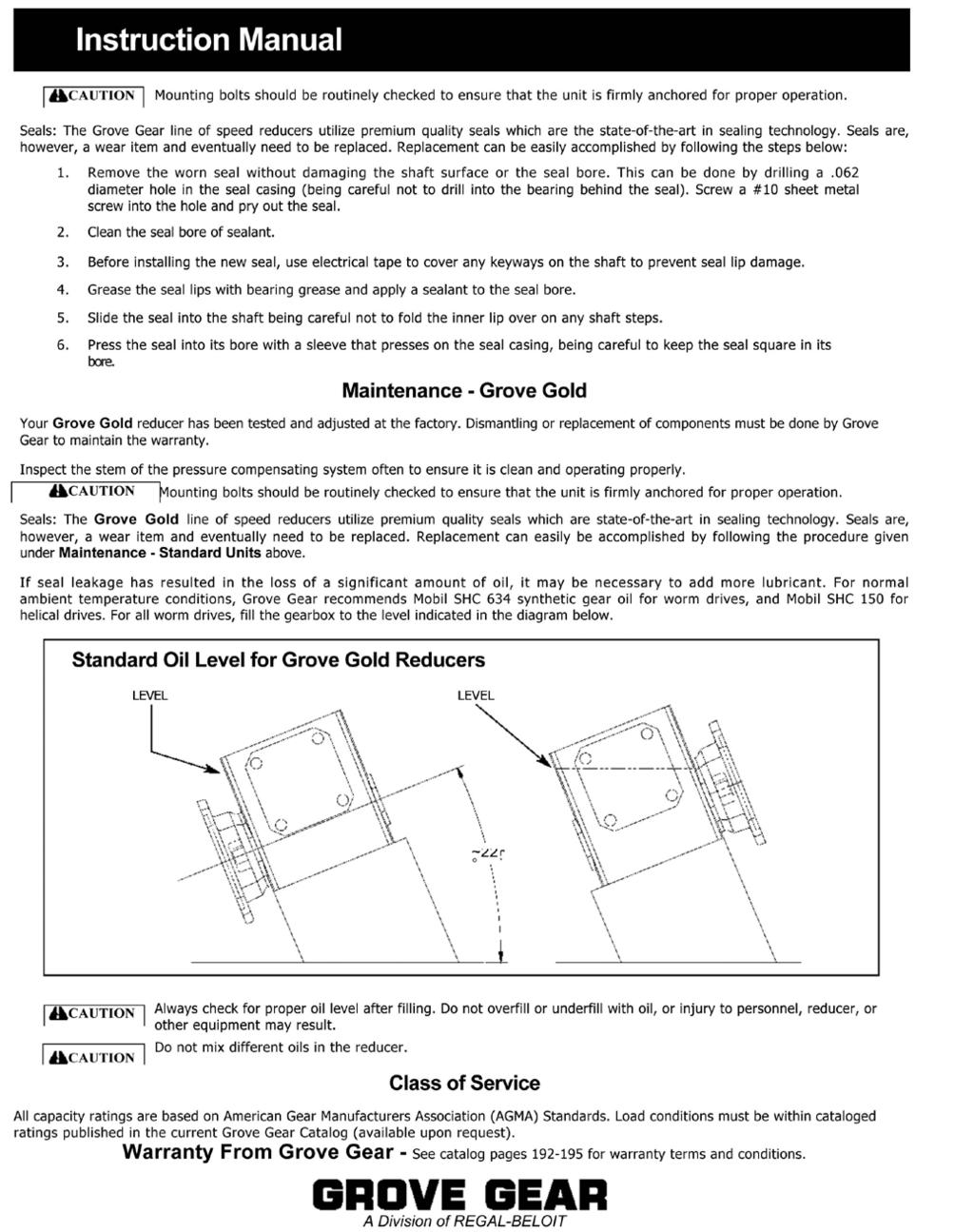
1 SM Installation, Operation and Maintenance Instructions EDDY CURRENT SEPARATOR Model ECS xtreme ERIEZ MAGNETICS HEADQUARTERS: 2200 ASBURY ROAD, ERIE, PA U.S.A. WORLD AUTHORITY IN ADVANCED TECHNOLOGY FOR MAGNETIC, VIBRATORY and INSPECTION APPLICATIONS
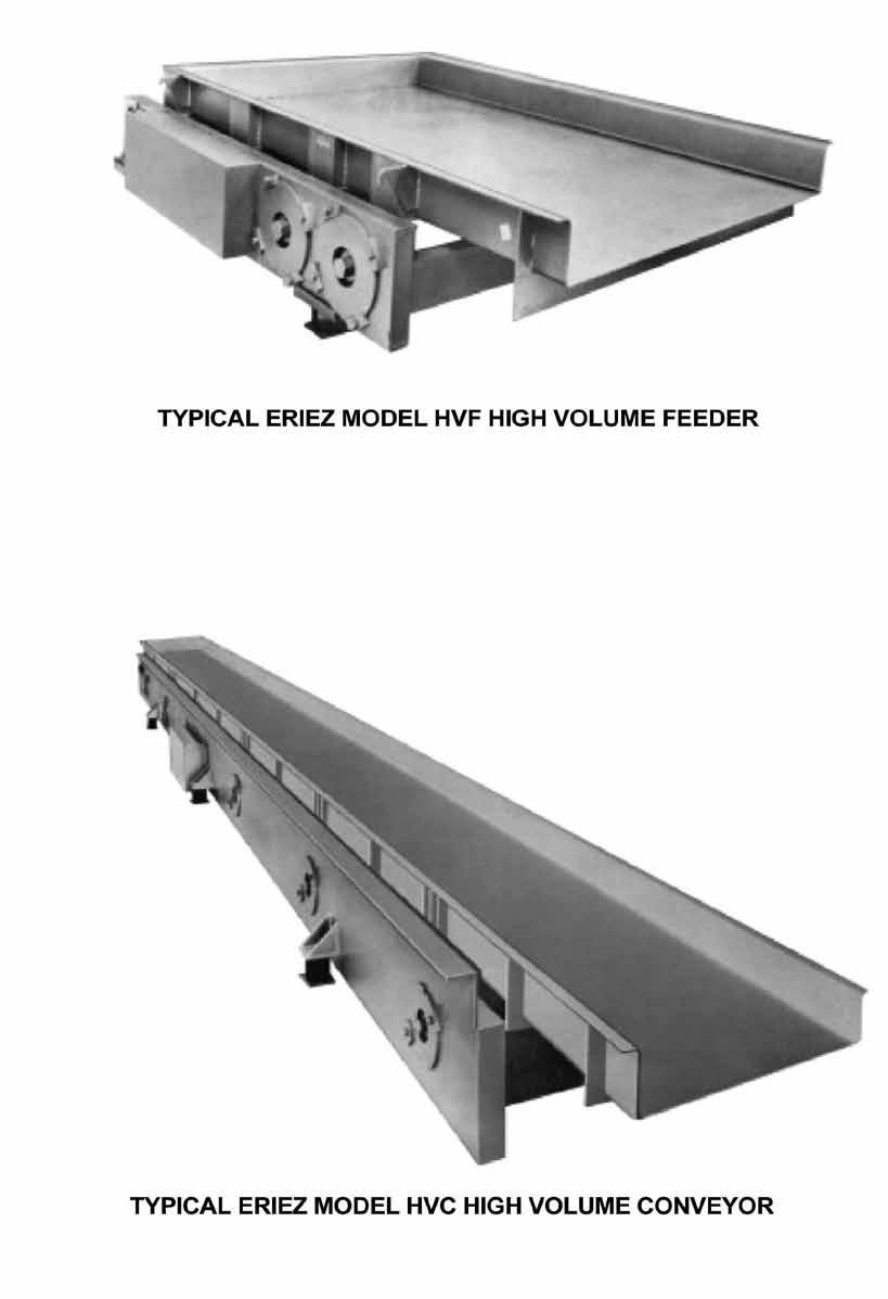
2 Table of Contents Eddy Current Separator Principles of Operation General Description Warning Installation Operation Splitter Setting Maintenance Pulleys and Rotor Devcon Ceramic White Resin and Hardener Conveyor Belt Gear Reducer Bearings Replacement Replacement of Rotor Pillow Block Bearings Replacement of Inner Shell Bearings Shell Replacement Tail Pulley Pillow Blocks Bearings Maintenance Tail Pulley Pillow Blocks Rotor Pillow Blocks Inner Shell Bearing Sheaves and V-Belts Daily Preventative Maintenance Required Maintenance ECS Separator Belt or Rotor Installation Procedure Belt Change Procedure Rotor Installation Procedure Belt Repair Kit Information Manufacturer s Information Flex-A-Line Speed Reducers Instruction Manual Engineering Data Eriez HVF Feeders & HVC Conveyors Installation, Operation and Maintenance Instructions
3 Principles of Operation The nonferrous metallic separator consists of an external drum, an internal permanent magnetic rotor, a drive, and belt conveyor. The external drum shell of non-metallic composite material rotates at conventional speed. The internal full diameter Rare Earth alternating polarity rotor turns at much higher RPM than the external shell. Through the induction of eddy currents and the resulting repelling forces, the alternating magnetic field selectively repels the nonferrous metals and physically separates them from other materials with minimum product loss. 3
4 General Description The Eddy Current Separator Xtreme (ECS) is furnished with a 14" diameter eddy current rotor, tail pulley, pillow block bearings, conveyor belt side guides, protective hood, and optional product discharge hoppers and splitter assemblies. The frame is of welded structural steel construction. The rotor drive consists of an electric motor, coupled to the rotor by sheaves and matched V-belts with a fully enclosed belt guard. The rotor speed can be of fixed or variable speed depending on options purchased. (See Electrical section of this manual for details.) The conveyor belt drive consists of an electrical motor, with a shaft mounted gear reducer on the tail pulley shaft. The belt speed can be fixed or variable speed depending on options purchased. (See Electrical section of this manual.) The ECS is shipped completely assembled. The optional pan feeder and control are separate and require hook-up. The Eddy Current Separator is designed to operate with a minimum amount of ferrous material in the waste stream. If necessary, Eriez Drum, Pulleys and Belt Magnets should be placed upstream to remove this material. Eddy Current Separator Application Rev XE Light Duty Material Recovery Facility (MRF) Metals Sorting 3" Products REA Type Eddy Xtreme Eddy Many MRFs Majority of Applications including...asr Shredder Fluff, MRF, MSW, Plastic, Glass, Ash, Foundry, Computer Scrap 4
5 WARNING PROVISION MUST BE MADE TO SHUT DOWN THE USER FEED CONVEYOR BEFORE STOPPING THE EDDY CURRENT SEPARATOR. THIS WILL PREVENT MATERIAL LAYING ON THE SEPARATOR CONVEYOR BELT WITH THE ROTOR STILL COASTING. STRAY FERROUS LAYING IN THE ROTOR AREA COULD HEAT UP AND CAUSE DAMAGE TO THE BELT AND ROTOR. 5
6 Installation Use care in uncrating to avoid damage to the equipment. Unit has been adjusted and tested at the factory prior to shipment. Pulleys have been installed with care to provide alignment of shafts and bearings. If there is a question of damage to the separator from rough handling in shipment, shaft alignment and belt adjustment should be checked. Particularly check the Electrical Control for any concealed damage to terminal boards, etc. When preparing to bolt the unit in the installation, shims should be used to ensure that all legs are sitting on a firm surface. The ECS should be leveled square. Do not pull bolts to frame by tightening, but shim from mounting surface to legs to prevent any twisting of the frame when hold down bolts are tightened. Note that all support legs should be supported rigidly from below. Optional feeder shall be shipped either loose or secured on frame work. If loose, feeder shall be lifted and placed onto mounting pads. If on frame work, release securing cables/straps that hold feeder. Turn now to the Electrical section of this manual to wire and check the control. 6
7 Operation A. Clear the installation area of any loose tools or other materials which may be attracted to the magnetic rotor. The main disconnect and Eddy Current Separator hatch panels, if supplied, must be closed. The Emergency Stop switch must be pulled out. B. Manual Mode (Local) The hand mode of operation is primarily intended for maintenance. The rotor will not run in this mode as it is possible to damage the shell or conveyor belt if the rotor is running with the conveyor off. Move the auto-hand selector switch into the hand mode. Push the conveyor start button to start the conveyor belt. Note that the conveyor start/stop push buttons only work in this mode. Momentarily start the conveyor drive in the "Hand Mode" and observe the direction of the belt. If belt rotation is incorrect, check the motor leads. If belt adjustment is necessary, due to misalignment during shipping, reposition the bearings on the tail pulley by take-up screws on either side of the pulley. Do not over tighten, as it is possible to pull the rotor shell into the rotor. It may be necessary to loosen one side rather than tighten the other to track the belt. The belt should only be tightened enough to allow the belt to run and track properly. Check the guides along the lower edges of the side guide. They should be within 1/8" of the belt. Improperly adjusted guides can cause damage to the belt. C. Auto Mode (Local) Push System Start push button. The conveyor starts first followed by the rotor. Note: The start button must be held for a second or two for the speed switch to close. With the conveyor tracked and running, observe the direction of rotation of the rotor. If the rotation is wrong, check motor leads. To stop, push the Emergency Stop Button. D. Automatic Mode (Remote) The system operates the same as in Local Automatic. The system will not run in remote mode if the hand-auto selector switch is in the hand mode. 7
8 Splitter Setting The splitter setting will vary depending on material being sent to the machine. Ideally a factory representative should be present during start-up to set the splitter and explain the various adjustments that may be required to optimize recovery. If one is not present and you are dealing with MSW or mixed recyclables, start with the splitter set 12" horizontally from the rotor surface and vertically set at the rotor centerline. Fine tune from this point. Typical splitter gaps for aluminum beverage cans are 12" on Ferrite, 15-18" on REM, and 20-24" on RE. Alternate method: Run product on conveyor with rotor off, and set splitter approximately 1-2" in front of material trajectory. 8
9 Maintenance A. Pulleys and Rotor The Eddy Current Separator is designed to operate with a minimum amount of ferrous material in the feed. For this reason, the rotor shell must be checked daily for any metallic particles stuck to the O.D. This is done by turning the machine off, opening the access door and rotating the rotor shell by hand to view the entire circumference. Remove any foreign matter immediately. Serious damage to the rotor shell will occur if cleaning is not done on a regular basis. Shell surfaces with missing tile(s) can be repaired with brushable ceramic (Devcon). See attached sheet. The magnetic rotor in an Eriez Eddy Current Separator incorporates high strength permanent magnets arranged in a special circuit. These magnets are bonded to the rotor hub and are then wrapped under tension with carbon fiber, using a proprietary process. Eriez has analyzed and tested the bonding and wrapping processes and the resulting rotor structure (including a test to destruction) to assure the integrity of the complete assembly. Because the rotor operates at high speed in close proximity to personnel and other equipment, failure could result in severe damage and/or personnel injury or death. It is important that the rotor structural integrity not be compromised by third party repairs. Any repair affecting the structural integrity of the ECS high speed rotor should be carried out only by Eriez or Eriez technicians. CAUTION! NEVER ATTEMPT TO CLEAN THE MACHINE WHILE IT IS RUNNING! 9
10 10
11 11
12 Maintenance (cont.) B. Conveyor Belt Check the conveyor belt for holes cuts, etc. that go all the way through. Patch immediately as fine materials will go through to the shell and cause severe damage. Worn areas of the belt should also be repaired to prevent the eventual formulation of holes. The belt is a urethane conveyor belt with cleats and sidewalls. Most rips, punctures, cuts, etc. can be quickly repaired with the optional belt repair kit, which includes a heat gun, fabric, tools, clamps and instructions in a plastic case. The kit, Eriez part number , is highly recommended. Observe the belt tracking while the machine is warm and running. if necessary, adjust. Because the eddy currents are shallow, thin belts (i.e., 1/8" or less) increase separation. However, thin belts are more susceptible to wear through and possible contamination of the shell surface with ferrous material. Experience should be your guide on optimum belt thickness for your particular application. If a spliced belt is used, make sure the lacing is non-metallic and is covered both top and bottom with a flexible flap cold vulcanized to the belt. Exact replacement endless belts are available from Eriez. To replace the belt with an endless belt all guards, covers and the slider plate need to be removed, as well as the conveyor drive pulley. Remove the four bolts from each side of the rotor pillow blocks see drawing 4N for reference. Do not remove the pillow block Item 6 from the frame. They are located and shimmed in place with a fixture at the factory. If it is ever necessary to remove them from the frame, take care to scribe around its base to make sure it is returned to its original location along with any shims that may have been used. Remove the sheave from the driven end and place a 6-foot long 2-3/4 ID tube or pipe over the drive shaft. Place the new belt on the pipe toward the rotor. Lift the rotor clear of the pillow blocks with a sling on the end of the pipe or tube and a sling on the non-drive side of the rotor. Slide the new belt over the rotor. Lower the rotor to the pillow blocks and bolt it back in place. Reinstall the sheave, the conveyor drive pulley, the slider plate, and all guards and covers. Re-track the belt. C. Gear Reducer Refer to individual section for manufacturer's instructions. D. Bearings Replacement The ECS incorporates three pairs of bearings: The rotor pillow block bearings (item 12 in attached drawing 4N ), the inner shell bearings (item 11), and the tail pulley pillow block bearings. Each has its own lubrication requirements. (See Bearing Maintenance) 1. Replacement of Rotor Pillow Block Bearings CAUTION: THE ECS ROTOR HAS A VERY STRONG PERMANENT MAGNET FIELD PRESENT ON THE SHELL SURFACE THAT WILL QUICKLY ATTRACT MAGNETIC TOOLS AND ITEMS TO THE SHELL SURFACE. EXTREME CARE MUST BE TAKEN TO KEEP ALL MAGNETICALLY ATTRACTIVE ITEMS AWAY FROM THE ROTOR TO AVOID INJURY OR SHELL DAMAGE. IF THE ECS ROTOR IS REMOVED FROM THE EQUIPMENT, USE EXTREME CARE TO KEEP ALL METAL ITEMS AWAY FROM THE ROTOR. a. Remove all guards, covers and the slider plate to access the rotor assembly. b. Relieve the tension on the conveyor belt at the tail pulley c. Loosen and remove the motor V belts, and remove the rotor drive sheave on the ECS shaft. d. Refer to drawing 4N and the two exploded view drawings showing the rotor bearing parts and shell details for the following instructions. e. Remove the hex head bolts (items 18) from the pillow blocks (item 6) on each side of the frame. NOTE: Do not remove the pillow block Item 6 from the frame. They are located and shimmed in place with a fixture at the factory. If it is necessary to remove them from the frame, scribe around pillow block base to make sure it is returned to its original location, and insure that the shims are placed in the proper location. 12
13 Maintenance (cont.) If the rotor pillow block and/or shell bearing is to be replaced on the machine, then it is necessary to lift the rotor off of the bearing pillow blocks and place it on a stiff wood structure supported on the frame between the pillow blocks and the tail pulley. The wood support frame should also have wood stops on each side so that the ECS rotor cannot roll in either direction. To facilitate the non-magnetic support frame, the ECS drive motor should be removed. Ensure that the tail pulley is far enough away from the ECS rotor so that it is not attracted to the ECS rotor. Place a nonferrous barrier (wood blocks) between the tail pulley and ECS rotor on support frame for a safe work environment. f. Loop a sling around each grease cover (item 3), and lift slowly until the shell support (item 10) clears the pillow blocks (item 6) and lower the rotor until it makes contact on the suitable nonferrous nonmagnetic (wood) work surface. An alternate lift location is to screw bolts into each end of the ECS shaft, and sling around the bolts. It may also be useful to have a 6-foot length of 2-3/4 ID tubing or pipe to slide over the drive side shaft to aid in moving the rotor from under the belt. With either rotor removal method, be certain that the rotor does not come in contact with the tail pulley g. Remove the bearing covers items 7 and 8 by removing the hex head bolts items 16 and 18. h. Remove bolts (item 20) fastening the bearing housing (item 9) from the shell support (item 10). i. Straighten the locking tab and remove the locknut item 23. Remove the socket head cap screws item 20 and slide off the bearing housing item 9. If it resists removal use two 1/2-13 bolts threaded into opposite tapped holes to push it off. Note the 1/8-inch notch for grease in the bearing housing item 9 should be positioned downward when reassembling. j. Fashion a bearing puller similar to that shown on drawing 4N Using the puller remove the bearing item 12. A minimal amount of heat can be applied to the inside bearing race to reduce the press fit between the bearing race and the shaft for ease of bearing removal. k. After bearing is removed, allow the shaft to cool (if heat was applied) and inspect shaft surfaces for nicks or burrs. Lightly file off any imperfections that would inhibit proper bearing installation onto the shaft. Remove all of the old grease from the bearing housing l. Install the new bearing onto the shaft. Never hit the bearing races directly with a hammer, and never tap on the outside bearing race. Use a soft aluminum tube that fits over the shaft and only contacts the ID race. Use a brass or dead weight hammer to impact the tube to drive the bearing onto the shaft. The bearing can be heated via a bearing heater or an oven to 200F to reduce the press fit on the shaft to assist in driving the bearing on the shaft. m. Install the bearing housing and covers in the reverse order that they were removed. Always take care not to impact or adversely load the bearing races during re-assembly. n. NOTE: Make certain that grease purge holes in the bearing housing (item 9) aligns with the purge hole in the shell supports (item 5 and item 10) o. Thoroughly pack the bearings with grease (Mobil Polyrex EM) until the grease purges through the pressure relief cavity located in the shell supports (items 5 and 10). Look between the shell bearing cover and the shell support to visually determine when the grease begins to purge through the pressure relief cavity. p. Replace the ECS rotor back into the pillow blocks, Make certain that the grease purge in the shell support is located in the bottom most location, and bolt the shell support to the pillow block. q. Remove the bearing covers and scoop out half of the grease from the top half pf the covers and the top half of the grease from against the bearing race. Make certain that clean tools/rags are used, and do not nick the race or any bearing balls. NOTE: Removing this amount of grease will provide the volume required to accept the grease that is purged from the bearing raceways during operation. This purging will reduce the friction between the grease and the moving parts of the bearing, and allow the bearing operating temperature to cool to roughly 30 F above ambient. Failure to remove the grease will result in the bearings operating hotter for a longer amount of time until the grease leaches through the shell support purge or labyrinth 13
14 Maintenance (cont.) seals. Extended high temperature operating periods will shorten grease life. r. Replace bearing covers. s. Clean the drive side shaft and install the drive side shaft seal (item 24). Place a small amount of grease between the bearing housing and the shaft seal to keep dirt from entering the labyrinth seal in the bearing cover. t. Reassemble the ECS machine in the reverse order that it was disassembled. Make certain that the pulley belts are properly aligned between the motor sheave and ECS shaft sheave Fig. 1 14
15 Maintenance (cont.) 15
16 Maintenance (cont.) 2. Replacement of Inner Shell Bearings a. Remove the rotor pillow block bearings per instructions provide in the replacement of rotor pillow block bearings section b. Remove the shell supports (item 5 and item 10) from the shaft. c. Remove flat head socket screws (items 21) from the grease cover (item 3). d. Remove flat head socket screws (items 19) and slide the end flange (item 4) off of the shaft. e. Tap the bearing(s) out from the backside of the end flange item 4 f. Install the new bearing by gently tapping the bearing outside race into the end flange with a block of wood and hammer. g. Remove all of the old grease from the grease cover, and fill with new grease (Mobil Polyrex EM) h. Reinstall the grease cover on the end flange and pack the grease cover until grease is purging from around the entire shaft. i. Reinstall the Shell support, and follow the rotor bearing installation instructions from the REPLACEMENT OF ROTOR PILLOW BLOCK BEARINGS section. 3. Shell Replacement To replace the shell, the ECS rotor should be removed from the machine and taken to a clean work area. a. Remove side guides and slider bed from the ECS machine b. Loosen the tail pulley bolts and remove the motor drive assembly from the pulley shaft and slide the tail pulley forward to provide as much belt slack as possible. c. Remove the tail pulley pillow block bearing bolts from the frame. d. Lift the tail pulley and slide a wood support structure underneath the tail pulley. e. Slide the tail pulley out from the frame far enough slip the belt off of the tail pulley. Keep the tail pulley supported so that it cannot drop off of the frame. f. Lift the tail pulley up, and remove the wood support structure to allow the belt to drop. g. Replace the tail pulley and bolt the pulley pillow block bearings to the frame h. Remove the ECS rotor (with belt) from the rotor pillow blocks per the instructions provided in the REPLACEMENT OF ROTOR PILLOW BLOCK BEARINGS section. Move the rotor to a clean area to remove the shell. i. Remove the rotor pillow block bearings and the shell end flange as instructed in the REPLACE- MENT OF ROTOR PILLOW BLOCK BEARINGS section and REPLACEMENT OF SHELL INNER BEARINGS sections j. Support the non-drive ECS shaft on a block of wood and use a six foot long 2-3/4 inch ID pipe to lift the drive side shaft high enough to slip the shell off of the rotor. Place a block of wood under the drive side shaft and lower the pipe until the shaft is supported on the wood block. k. Slip the pipe off of the shaft, remove the old shell, and replace a new shell on the pipe. l. Clean and inspect the rotor for damage, Small lines or grooves in the carbon fiber wrap are acceptable. However, wrap damage greater that is greater than a 1/2 inch groove should be brought to the attention of Eriez Magnetics Service department for consultation. m. Slip the pipe back on the shaft, lift the ECS rotor and slide the new shell over the rotor. n. Follow the instructions for replacing the inner shell bearings and rotor pillow block bearings in the respective sections in this guide. Eriez recommends that new bearings be used if bearings were removed from their housings. Reinstall the rotor in the machine and reinstall the belt over the tail pulley in the reverse order that the belt was removed from the tail pulley. Re-install the slider bed and all guards in the reverse order that they were removed. 4. Tail Pulley Pillow Blocks. To remove or replace a bearing, loosen the set screws on its collar and pull it from the shaft. 16
17 Maintenance (cont.) E. Bearings Maintenance 1. Tail Pulley Pillow Blocks. Lubricate every two months with a lithium base NLG1 grade 2 grease. The bearings should be lubricated while rotating and the grease pumped in slowly until a slight bead forms around the seals. 2. Rotor Pillow Blocks. Lubricate every 6 months with Mobilith Polyrex EM or equivalent. The bearings should be lubricated while rotating using the top offset grease fitting. Add.5oz (12" through 48" wide units) or.7oz (60" wide units) of grease. After 1 year of lubrications, remove the bearing cap and remove all of the old grease. Refill the housing 1/2 full of grease, 6.3 oz (12" through 48" wide units) or 6.8oz (60" wide units). 3. Inner shell bearing The inner shell bearing grease purge chamber incorporates grease fittings. The actual bearings are lubed and sealed for life; the grease injected through the fitting in the purge chamber is intended to provide an additional seal to prevent damage from contamination. The grease will purge out around the shaft area, thereby, flushing out contaminants. Check the shaft in this area at least every two weeks for visible grease. If no grease is visible, clean the area between the shaft and the grease retainer and add only Mobilith Polyrex EM grease through the fitting until grease is discharged around the shaft. A relief plug is provided and should be removed during lubing so as not to damage the bearing seal with excessive pressure. F. Sheaves and V-Belts Check for shiny spots, frays or splits. Replace as required. G. Daily Preventative Maintenance See decal on ECS, a copy of which is shown on the following page. 17
18 Required Maintenance IMPORTANT! TURN OFF AND LOCK OUT POWER TO THE EDDY CURRENT SEPARATOR WHILE CARRYING OUT ALL PROCEDURES WHICH INVOLVE CONTACT WITH THE MACHINE. FAILURE TO DO THIS MAY RESULT IN SERIOUS PERSONAL INJURY OR DAMAGE TO THE EDDY CURRENT SEPARATOR. DAILY: Check for and remove any metal particles stuck to the belt or the outer surface of the rotor shell. Check for and remove debris build-up on and around the motors. Check for and remove debris build-up on the splitter and discharge chutes. Check for and patch holes and worn spots on the conveyor belt. Adjust side guides and brushes for minimum clearance to the conveyor belt (plastic guides 1/4"). Remove any material build-up in the side guide brushes (if fitted). Observe and adjust conveyor belt tracking after the machine warms up. Check the feeder tray (if any) for material build-up and clean as required. CAUTION! Door must be closed while unit is running. Failure to observe this precaution may result in damage to the machine and/or serious personal injury. IMPORTANT! With unit turned off check rotor shell for ferrous contamination on a daily basis MAXIMUM ROTOR SPEED 2600 RPM EVERY TWO WEEKS: Add Mobil PolyrexEM AW3 or Mobil XHP223 or equivalent at the fittings at the end of the rotor until grease is discharged around the shaft. Check and lube the tail pulley bearings as specified in the IOM. 18
19 ECS Separator Belt or Rotor Installation Procedure The following procedure is recommended for the installation of an endless conveyor belt or a new or replacement rotor for an Eddy Current Separator. Special items required are two 3" ID pipes eight feet long. These pipes will slide over the ends of the rotor and tail pulley shafts during belt removal or replacement. A. Belt Change Procedure 1. Working from the drive side, remove the belt guard, driven sheave, V-belt and loosen the reducer torque arm. 2. Remove both side guide assemblies from the machine. If you have a standard unit skip to step Remove side guide access hatch, Fig 1 marked "A" (flip three latches). 4. Remove remaining top half of side guide, Fig 1 marked "B" (four bolts to side guide supports). 5. Remove bolts on side guide supports (4), Fig 1 marked "C", releasing slide plate. Remove. 6. Remove four nuts holding bottom half of side guide, Fig 1 marked "D". Remove bottom half. 7. Slice belt across width and remove towards the front of the unit from the underside while standing in first discharge chute. 8. After the belt is removed, inspect rotor shell carefully for any damage. If there is any evidence of a shell breach, notify factory immediately. 9. While in the process of installing the new belt, do not allow any material to attach itself to the rotor. If the ECS is allowed to run with material stuck to the shell, severe damage could occur 10. Loosen pillow blocks and take up on tail pulley, Fig 1 marked "E". It may be helpful to remove the motor from the reducer as this is a shaft mounted unit and the motor will swivel downward if the support arm is removed to allow full adjustment of the take up. Mark the location of the rotor pillow blocks. 11. Clean out any material that may be caked up inside the lower side guides or around brushes. 12. If installing a belt that is weld spliced, reference instructions supplied in welding kit. B. Rotor Installation Procedure 1. Ensure that the magnetic rotor is clean and free of any foreign objects. 2. Slide pipes onto rotor drive side and tail pulley shaft ends. (See Fig 2.) 3. Place belt onto pipe. 4. Lifting the tail pulley and rotor with the pipes, slide the belt into place. See Fig 2. Fig Reinstall pillow block bearings at the original locations. 6. Replace V-belt, Sheave, belt guard and readjust reducer torque arm. 7. Adjust belt for proper tracking. Be careful not to over tension the belt, as the shell that surrounds the rotor could be pulled into the spinning rotor and result in damage. 8. When the belt is tracking at the center at the pulleys, readjust the belt skirting to within 1/8" of belt surface. Check the tracking on the underside of the unit to make sure the side walls are not rubbing along the side guides. 9. Allow the unit to run at least 30 minutes prior to running material while closely monitoring the belt tracking. 10. Continue to monitor the belt tracking periodically. The belt may need some break in time and this could result in the belt tracking off and causing damage to the belt. 19

20 ECS Separator Belt or Rotor Installation Procedure (cont.) C. Belt Repair Kit Information Welding Kit Contains all the necessary tools and materials required to splice all styles of conveyor belting endless by heat welding. Description Quantity 1. NOVITANE Welding Procedure Manual 1 only Gauge Galvanized Steel (4" wide x long) 2 each 3. NOVITANE Welding Rod - 3 sizes 1/8" Round 75 Ft. 5/32" Triangular 50 Ft. 1/4" Triangular 50 Ft. 4. Stelnel Hot Air Gun #HG-2000-E with a 9 mm nozzle, 1 only 5. Welding Trial Belt Samples IG COS (12) 3 each FG-90/85 K (8) 3 each 6. Teflon Coated Glass Fabric (010" x 72" wide x 12" long) 1 only 7. Spring Clamps (2" opening x 6" long) 4 each 8. Cutting Pliers 1 only 9. Roller (1" wide x 1" diem) 1 only 10. Angle Head Utility Knife 1 only 11. Carrying Case 1 only 20
21 Manufacturer s Information 21
22 22
23 23
24 24
25 25
26 26
27 27
28 28
29 29
30 30
31 31
32 32
33 Installation, Operation and Maintenance Instructions HVF Feeders and HVC Conveyors ERIEZ MAGNETICS HEADQUARTERS: 2200 ASBURY ROAD, ERIE, PA U.S.A. WORLD AUTHORITY IN ADVANCED TECHNOLOGY FOR MAGNETIC, VIBRATORY and INSPECTION APPLICATIONS 33
34 Table of Contents ERIEZ HVF FEEDERS AND HVC CONVEYORS Introduction Installation Shipping Damage Handling Installation Warning Hopper Design and Feeder Capacity Wiring Special Troughs and Attachments Operation Deflection Deflection Adjustment Maintenance Lubrication Adjustments Spring Replacement Belt Replacement Bearing Replacement Spare Parts Troubleshooting
35 Introduction This manual describes Eriez new mechanical vibrating feeders and conveyors. The easy-to-clean, all-metal pans provide low cost movement to a wide variety of materials. The pans can be supplied open or enclosed, with liners or screens, and with a variety of inlets and outlets. A careful reading of these Installation, Operation and Maintenance Instructions will assure the most efficient and dependable performance of this equipment. Please include the model and serial number found on the nameplate with any correspondence concerning your feeder or conveyor. CAUTION: Safety labels must be affixed to this product. Should the safety label(s) be damaged, dislodged or removed, contact Eriez for replacement. WARNING: Suspension mounting inherently involves risk of damage to property or injury to personnel located under or near the equipment, should a suspension component fail. As with all suspended equipment, access to the area under this machine should be restricted. Specifications for suspension components given in this manual are suggestions only, and the user is entirely responsible for final selection of suspension method and details. Select and properly use suspension components with rated capacities (including all appropriate reduction factors) that provide adequate safety when the weight of the equipment and all possible loading conditions and upsets are taken into account. Consult Eriez at if additional information regarding Eriez equipment is needed to make this selection. 35
36 36 Introduction (cont.)
37 Installation Shipping Damage When you receive your feeder or conveyor, examine it carefully for damage. If damage is found, report it immediately to Eriez Magnetics and the carrier. Handling It is important to handle this equipment carefully to avoid twisting or bending the frame or pans. If lift lugs are provided, they must be used; otherwise, lift with slings. A spreader board over the pan should be used to prevent your chain or cable from bending the pan while lifting. An excessively large amount of weight placed on the pans or springs could damage the unit. Installation Feeders are usually suspended from hooks on the pan with rubber isolation springs. Base mounting is used only where the headload from customer s material is small. The isolation assemblies should be welded to suitable overhead structure or hopper (Figure 1). Wire rope and/or turnbuckles may be used for greater suspension heights. For proper operation, all suspension points should have nearly equal tension. When base mounting is used, attach the spring pads provided to floor or framework. Be sure that there is adequate clearance between any solid object and the pan or base. Feeders are usually suspended with a downslope of up to 10 degrees. At this downslope the Model HVF feeders can attain velocities of up to 100 feet per minute (.5 mps), depending upon material characteristics. Warning: Suspension components provided by Eriez have been properly sized for the equipment weight and normal operating loads, including reasonable upset conditions and safety factors. However, the design cannot take account of extreme operating or installation conditions of which Eriez may not be aware. The ultimate decision as to the adequacy of any suspension component, whether Eriez-supplied or customer-supplied, is the responsibility of the installer and user. You should select all suspension components with proper consideration of the equipment weight, normal and upset operating loads, and safety factors. If you need any further information about the equipment characteristics for your suspension design, please contact Eriez. The suspension design itself should be carried out by properly qualified engineering personnel. Failure to observe these precautions can result in death, serious personnel injury, and/ or equipment damage. Hopper Design and Feeder Capacity For vibratory feeders to perform at maximum capacity, it is important to design bins and hoppers for optimal material flow patterns. This is best achieved with the following guidelines. The hopper throat opening T (see Figure 1) should be at least 2.5 times the largest particle diameter, for randomly sized material. Diameter here refers to the size of the largest circle that will barely con tain an irregularly-shaped particle. For applications with all particles nearly the same size, T should be 5 times the nominal particle diameter. T = Hopper-Throat Opening H = Gate-Height Opening 37
38 Installation (cont.) Best flow patterns result when the gate height H is at least twice the throat dimension T, as shown in Figure 2. Values of H equal to T are acceptable, but when H becomes less than T material flow patterns are not uniform and usually result in dead zones where little or no flow occurs, as shown in Figure 3. The capacity of a vibratory feeder is given by: Q = (W x d x D x v) / K Where English Metric Q = capacity TPH MTPH W = tray width inches mm d = material depth inches mm D = material density lb/cuft g/cu cm v = flow velocity ft/min m/min K = constant 4,800 16,700 Wiring Wiring to the motor should enter from a flexible conduit. Use of a motor starter and circuit protection is recommended. Wiring must be properly sized to prevent line voltage drop. Motors commonly supplied are 1725 rpm, dual voltage polyphase. Connect wiring according to the manufacturer s instructions, usually located on the nameplate or in the conduit box cover. Motor rotation should be such that the top of the pulley rotates in the opposite direction from the feed of the pan. However, some materials feed better with the belt turning in the same direction as the feed. When controller is supplied connect according to instructions enclosed with this equipment. Special Troughs and Attachments Eriez Engineering Service Department should always be consulted before undertaking the design or construction of special troughs. The troughs as furnished by Eriez should not be modified or attachments added without first consulting Eriez, as the feeders and conveyors are a tuned mass system and damage will result. Doing so will void the warranty. Along with the hopper design, the flow velocity v depends on material characteristics such as particle size, size distribution, and moisture content. 38

 and touching the pan side with the pencil point while the pan is operating.")
39 Operation Deflection Eriez mechanical conveyors and feeders are normally set at approximately 7/16-inch (11 mm) pan deflection. This can be checked with an Eriez deflection sticker. The sticker is read while the equipment is operating by looking at the optical illusion in which the printed circles appear as double. Read the deflection where a pair of circles just touch together. A deflection sticker is shown actual size in Figure 4. The deflection may also be read by holding a pencil very steadily (resting against a solid object) and touching the pan side with the pencil point while the pan is operating. Then stop the equipment and measure the deflection indicated by the line drawn on the side of the pan. Do not operate at pan deflections greater than 7/16-inch (11 mm) because spring damage will result. The total of pan deflection and base deflection must not exceed 11/16-inch (17 mm). These deflections should be taken at full voltage and with material feeding at maximum capacity. Deflection Adjustment The deflection may be changed by means of the adjustable drive sheave. Making the sheave smaller in pitch diameter will slow down the eccentric shaft and decrease the deflection. Increasing the drive sheave pitch diameter will increase deflection. To adjust the drive sheave: 1. Loosen motor plate mounting bolts (Figure 5). 2. Slide motor plate forward to loosen belt. 3. Loosen set screws that lock sheave halves. 4. Turn sheave haives so they move apart to decrease the pitch diameter or turn the opposite way to increase diameter. 5. Replace key and tighten set screws. 6. Reinstall belt and pull motor tight against belt. 7. Tighten motor plate mounting bolts. If the driven sheave is removed, the tapered bushing must be carefully tightened to prevent slipping on the shaft. Tighten each bolt in the bushing until each is tightened to about 10 ft. Ib (7 Nm). Be sure to recheck the torque because tightening one bolt will loosen the others. NOTE: Material build-up on pan may increase pan deflection and cause tray, base or tuning spring failure. CAUTION: Do not operate the unit with any associated equipment in direct contact with any part of the vibratory unit. 39

40 Operation (cont.) The manual variable speed drive (MVS) consists of a variable pitch sheave with an adjustment handwheel on the motor and a spring loaded companion sheave on the eccentric shaft. The companion sheave will change pitch diameter in response to changes made to the adjustable motor sheave while remaining at the same center distance. In operation, turning the handwheel counterclockwise while the motor is running will increase the speed and deflection and turning the handwheel clockwise will decrease speed and deflection. The motor sheave has an internal maximum speed stop which is factory set; however this stop may be overpowered and damaged by continued turning the handwheel with excessive force after the maximum speed stop has become engaged. This will cause the unit to over-deflect beyond its design deflection and cause premature failures. When the handwheel is turned to the point where the maximum speed stop is engaged, DO NOT FORCE IT TO TURN ANY FURTHER! When replacing belts, be sure to set the motor at the same center distance as it came from the factory. Incorrect center distances will cause the maximum speed to increase which will cause the unit to over-deflect and fail. To set the proper center distance, you must open the motor sheave until the belt can ride at the smallest pitch diameter at the bottom of the groove. Then position the belt in the driven sheave so that the top of the belt is even with the outside diameter of the driven sheave (at the maximum pitch diameter). Slide the motor mount back until there is some tension on the belt and lock the mount in that location. Upon starting the motor, turning the handwheel counterclockwise will give the proper belt tension. Some MVS drives use asymmetrical belts which means that one side of the belt is made at a different angle than the other. On these units it is necessary to install the belt so that the sides of the belt match the sides of the sheaves. 40

41 Maintenance Lubrication Bearings should be lubricated approximately every 200 hours of operation with grease gun suitable for roller bearings. This bearing is factory lubricated with No. 2 consistency lithium base grease which is suitable for most applications. However, extra protection is necessary if bearing is subjected to excessive moisture, dust, or corrosive vapor. In these cases, bearing should contain as much grease as speed will permit (a full bearing with consequent slight leakage through the seal is the best protection against contaminant entry). In extremely dirty environments, the bearing should be purged daily to flush out contaminants. For added protection, it is advisable to shroud the bearing from falling material. Adjustments DEFLECTION As mentioned earlier, the deflection is set at time of manufacture at approximately 7/16 inch (11 mm). Deflection may be adjusted by changing the speed as described in the preceding section. SPRING ANGLE Spring angle is factory set at the optimum setting. If special conditions warrant changing the spring angle proceed as follows (see Figure 8): The following table is a general guide for normal operating conditions. However, some situations may require a change in lubricating periods as dictated by experience. If the bearing is exposed to unusual operating conditions, consult a reputable grease manufacturer. 1. Loosen spring center bolt. 2. Loosen clamp bolts. 3. Rotate spring in the base channel to the desired angle. Normally all springs are set at the same angle. NOTE: Alignment marks on the spring frame represent Tighten clamp bolts. 5. Tighten center bolts and torque to required values. Torque spring center bolts as follows: If these springs are removed for any reason, they must be replaced and set at the same angle of inclination from the horizontal as originally set. When replacing motors, replace with an identical hp, rpm and voltage motor and insure all sheaves are in proper alignment. Excessive belt wear will result if belts are operated misaligned. Always replace worn belts. 41
 deflection at the midspan when moderate pressure is applied by hand. Excessively loose or tight belts will wear rapidly.")
42 Maintenance (cont.) Belt Periodically inspect the belt for tension and wear. The belt should be tensioned to allow approximately 1/2-inch (13 mm) deflection at the midspan when moderate pressure is applied by hand. Excessively loose or tight belts will wear rapidly. A new belt should be readjusted after a few hours of operation. Spring Replacement 1. Note angle at which old spring is set. 2. Remove old spring as shown (Figure 9). 3. Install new spring and set angle as described earlier. NOTE: It is best to replace springs one at a time so that the pan will be supported by the remaining springs. Bearing Replacement When replacing bearings DO NOT use set screws to attach collar to shaft. Doing so will cause premature bearing failure. The eccentric shaft must be able to move freely on the inner race of the bearing. 42
43 Spare Parts 43
44 Troubleshooting 2011 ERIEZ Manufacturing co. World Authority in Advanced Technology for Magnetic, Vibratory and Inspection Applications HEADQUARTERS: 2200 ASBURY ROAD, ERIE, PA U.S.A. Telephone 814/ / Fax 814/ International Fax 814/ Web Site: MANUFACTURING FACILITIES IN: AUSTRALIA BRAZIL CHINA INDIA JAPAN MEXICO SOUTH AFRICA UNITED KINGDOM UNITED STATES 211-1C-SSC-ARN 2011 ERIEZ MANUFACTURING CO. PRINTED IN USA 44
Installation, Operation and Maintenance Instructions
 SM-780-1 Installation, Operation and Maintenance Instructions EDDY CURRENT SEPARATOR Model ECS REA CARTRIDGE DESIGN 12 48 ERIEZ MAGNETICS HEADQUARTERS: 2200 ASBURY ROAD, ERIE, PA 16506-1440 U.S.A. WORLD
Installation, Operation and Maintenance Instructions
 SM-305J Installation, Operation and Maintenance Instructions Suspended permanent magnets ERIEZ MAGNETICS HEADQUARTERS: 2200 ASBURY ROAD, ERIE, PA 16506 1402 U.S.A. WORLD AUTHORITY IN ADVANCED TECHNOLOGY
Installation, Operation and Maintenance Instructions
 VM-3364L Installation, Operation and Maintenance Instructions VIBRATORY FEEDERS MODELS - 58B, 62B, 65B, 68B, 70B & 75B ERIEZ MAGNETICS HEADQUARTERS: 2200 ASBURY ROAD, ERIE, PA 16506 1402 U.S.A. WORLD AUTHORITY
Installation, Operation and Maintenance Instructions
 SM-328D Installation, Operation and Maintenance Instructions suspended electromagnets for hazardous locations se-700u series, manual cleaning Se-700usc series, self cleaning ERIEZ MAGNETICS HEADQUARTERS:
BELT CONVEYORS. Installation, Operation and Maintenance Instructions MJ-2800B
 MJ-2800B Installation, Operation and Maintenance Instructions BELT CONVEYORS ERIEZ MAGNETICS HEADQUARTERS: 2200 ASBURY ROAD, ERIE, PA 16506 1440 U.S.A. WORLD AUTHORITY IN ADVANCED TECHNOLOGY FOR MAGNETIC,
Installation, Operation and Maintenance Instructions
 SM-140C Installation, Operation and Maintenance Instructions Magnetic Humps and Round Pipe Separators ERIEZ MAGNETICS HEADQUARTERS: 2200 ASBURY ROAD, ERIE, PA 16506 1440 U.S.A. WORLD AUTHORITY IN ADVANCED
Installation, Operation and Maintenance Instructions
 MJ-2100G Installation, Operation and Maintenance Instructions S ERIEZ MAGNETICS HEADQUARTERS: 2200 ASBURY ROAD, ERIE, PA 16506 U.S.A. WORLD AUTHORITY IEPARATION TECHNOLOGIES 1 Magna-Rails Introduction
Installation, Operation and Maintenance Instructions
 SM-141 Installation, Operation and Maintenance Instructions MAGNEtic humps & round pipe separators ERIEZ WORLD HEADQUARTERS: 2200 ASBURY ROAD, ERIE, PA 16506 1402 U.S.A. WORLD AUTHORITY IN SEPARATION TECHNOLOGIES
Installation, Operation and Maintenance Instructions
 VM-3153B Installation, Operation and Maintenance Instructions Vibratory feeder model 26C ERIEZ MAGNETICS HEADQUARTERS: 2200 ASBURY ROAD, ERIE, PA 16506 1402 U.S.A. WORLD AUTHORITY IN ADVANCED TECHNOLOGY
Installation, Operation and Maintenance Instructions
 VM-3015F Installation, Operation and Maintenance Instructions Vibratory feeder model 15A ERIEZ MAGNETICS HEADQUARTERS: 2200 ASBURY ROAD, ERIE, PA 16506 1402 U.S.A. WORLD AUTHORITY IN ADVANCED TECHNOLOGY
INSTRUCTION MANUAL INTERNAL GEAR PUMP TITAN G-4124A SERIES=> FLANGED TITAN G-124A SERIES => FLANGED MODELS:
 INSTRUCTION MANUAL INTERNAL GEAR PUMP TITAN G-4124A SERIES=> FLANGED TITAN G-124A SERIES => FLANGED MODELS: G-H, G-HL, G-K, G-KK, G-L, G-LQ, G-LL, GLS, G-Q, G-QS 1 Contents Maintenance Thrust bearing adjustment
Installation and Maintenance Manual For. Dings Self-Cleaning Permanent Overhead Magnet
 Installation and Maintenance Manual For Dings Self-Cleaning Permanent Overhead Table of Contents General Information... 1 Installation Procedures Unpacking and Handling... 2 Storage... 3 Installation and
UNIT VIBRATOR MODELS 60U AND 70U
 VM-3560B Installation, Operation and Maintenance Instructions UNIT VIBRATOR MODELS 60U AND 70U ERIEZ MAGNETICS HEADQUARTERS: 2200 ASBURY ROAD, ERIE, PA 16506 1440 U.S.A. WORLD AUTHORITY IN ADVANCED TECHNOLOGY
feeder Vibratory feeder
 VM-3155C Installation, Operation and Maintenance Instructions Vibratory feeder model hs36 Vibratory feeder model 36C ERIEZ MAGNETICS HEADQUARTERS: 2200 ASBURY ROAD, ERIE, PA 16506 1402 U.S.A. WORLD AUTHORITY
Fluid-O-Tech ROTOFLOW ROTARY VANE PUMP REBUILD MANUAL
 Fluid-O-Tech PUMP TECHNOLOGY AT ITS BEST WWW.FLUID-O-TECH.COM Office: 161 Atwater St., Plantsville, CT 06479 Phone: (860) 276-9270 Fax: (860) 620-0193 ROTOFLOW ROTARY VANE PUMP REBUILD MANUAL 08/09 Ed.,
Jet Fans. Instruction Manual READ AND SAVE THESE INSTRUCTIONS WARRANTY
 Jet Fans Instruction Manual READ AND SAVE THESE INSTRUCTIONS WARRANTY All Leader Fan products are guaranteed to be free from defects of workmanship or material and to function satisfactorily when properly
Instruction Manual for HSPA Take-Up Units
 Installation Instruction Manual for HSPA Take-Up Units Warning: To ensure the drive is not unexpectedly started, turn off and lockout the power source before proceeding. Failure to observe these precautions
PERMANENT MAGNETIC AND RARE EARTH
 COOLANT CLEANERS PERMANENT MAGNETIC AND RARE EARTH Smooth-faced and extended-pole Coolant Cleaners extend the life of cutting tools, grinding wheels, pumps and coolant fluids. FEATURES & Benefits Cleaner
Maintenance Information
 16573370 Edition 2 February 2014 Air Grinder 99V Series Maintenance Information Save These Instructions Product Safety Information WARNING Failure to observe the following warnings, and to avoid these
MARLEY ENGINEERED PRODUCTS OPERATING INSTRUCTIONS AND PARTS LIST
 MARLEY ENGINEERED PRODUCTS OPERATING INSTRUCTIONS AND PARTS LIST TUBE AXIAL DUCT FANS INDUSTRIAL PROPELLER FANS INDUSTRIAL ROOF EXHAUSTERS HEAVY DUTY MAN/PRODUCT COOLERS WARNING BY ACCEPTANCE OF THIS MERCHANDISE,
Instruction Manual For DODGE. Airport Baggage Handling Systems Speed Reducers
 Instruction Manual For DODGE Airport Baggage Handling Systems Speed Reducers ABHS TXT109 - TXT115 - TXT125 ABHS TXT209 - TXT215 - TXT225 ABHS TXT309A - TXT315A - TXT325A ABHS TXT409A - TXT415A - TXT425A
INSTALLATION, OPERATION, AND MAINTENANCE MANUAL CNW DHK PVK
 FRP Centrifugal & Inline Fans Bulletin 90-01- NOV2002 INSTALLATION, OPERATION, AND MAINTENANCE MANUAL This publication contains the installation, operation and maintenance instructions for the following
Maintenance and Repair
 Maintenance and Repair WARNING ALWAYS shut off the engine, remove key from ignition, make sure the engine is cool, and disconnect the spark plug and positive battery terminal from the battery before cleaning,
TECHNICAL SERVICE MANUAL
 Electronic copies of the most current TSM issue can be found on the Viking Pump website at www.vikingpump.com TECHNICAL SERVICE MANUAL HEAVY-DUTY Stainless steel BRACKET MOUNTED PUMPS SERIES 127 AND 4127
MODEL VBO-HV & VBO UPBLAST PROPELLER ROOF FANS
 READ AND SAVE THESE INSTRUCTIONS 9668-D Heinrich Hertz Drive, San Diego, CA 92154 PH: 619-946-1224 MODEL VBO-HV & VBO UPBLAST PROPELLER ROOF FANS SHIPPING INSPECTION Romlair Model VBO-HV & VBO fans are
INSTALLATION, OPERATION AND MAINTENANCE MANUAL WALL EXHAUST FANS BELT & DIRECT DRIVE XB, HV, HVA, ADD, DDS, DDP
 INSTALLATION, OPERATION AND MAINTENANCE MANUAL WALL EXHAUST FANS BELT & DIRECT DRIVE XB, HV, HVA, ADD, DDS, DDP The purpose of this manual is to aid in the proper installation and operation of the fans.
READ AND SAVE THESE INSTRUCTIONS
 READ AND SAVE THESE INSTRUCTIONS Part #469003 Model Vektor -H Installation Operation and Maintenance Manual for Vektor-H Laboratory Exhaust System Receiving Greenheck model Vektor-H fans are thoroughly
SERIES G3DB/AG3DB ELEVATOR
 TM INSTRUCTIONS AND PARTS LIST SERIES G3DB/AG3DB ELEVATOR WARNING This manual, and GENERAL INSTRUCTIONS MANUAL, CA-1, should be read thoroughly prior to pump installation, operation or maintenance. SRM00059
Installation, Operation and Maintenance Instructions
 VM-3154B Installation, Operation and Maintenance Instructions Vibratory feeder model hs36 ERIEZ MAGNETICS HEADQUARTERS: 2200 ASBURY ROAD, ERIE, PA 16506 1440 U.S.A. WORLD AUTHORITY IN ADVANCED TECHNOLOGY
McCannalok HIGH PERFORMANCE BUTTERFLY VALVE OPERATION AND MAINTENANCE MANUAL. The High Performance Company
 McCannalok HIGH PERFORMANCE BUTTERFLY VALVE OPERATION AND MAINTENANCE MANUAL The High Performance Company Table of Contents Safety Information - Definition of Terms... 1 Introduction... 1 Installation...
Operation and Maintenance Manual. Series BI Centrifugal Blowers
 Operation and Maintenance Manual Series BI Centrifugal Blowers This publication contains the installation, operation and maintenance instructions for standard units of the Monoxivent Series BI-Centrifugal
TSL and QSL Inline Centrifugal and Mixed Flow Fans
 TSL and QSL Inline Centrifugal and Mixed Flow Fans INSTALLATION, OPERATION & MAINTENANCE MANUAL ES-89 September 07 Throughout this manual, there are a number of HAZARD S that must be read and adhered to
Installation, Operation and Maintenance Instructions
 FJ-201A Installation, Operation and Maintenance Instructions Oil Belt Skimmers Model 83-1000E, 83-1225, 83-2000E ERIEZ MAGNETICS HEADQUARTERS: 2200 ASBURY ROAD, ERIE, PA 16506 1402 U.S.A. WORLD AUTHORITY
MAGNETIC PULLEYS ERIEZ MAGNETICS
 SM-240E Installation, Operation and Maintenance Instructions MAGNETIC PULLEYS ERIEZ MAGNETICS HEADQUARTERS: 2200 ASBURY ROAD, ERIE, PA 16506 1440 U.S.A. WORLD AUTHORITY IN ADVANCED TECHNOLOGY FOR MAGNETIC,
CONTENTS. VIKING PUMP, INC. A Unit of IDEX Corporation Cedar Falls, IA USA SECTION TSM 710.1
 TECHNICAL SERVICE MANUAL industrial heavy duty motor speed pumps SERIES 4076 AND 4176 SIZES hle, ate and ale SECTION TSM 710.1 PAGE 1 of 8 ISSUE B CONTENTS Introduction....................... 1 Safety
A B C D E F. Tools Required (supplied by others)
") Page 1 of 17 Parts List Below Deck Automatic Retractable Security Cover Kit (1) Tube End Bearing Plate (A) (1) Rope Reel and Cover Drum Motor Assembly (B) (1) Cover Drum (1) Pulley Support Channel (2)
Page 1 of 17 Parts List Below Deck Automatic Retractable Security Cover Kit (1) Tube End Bearing Plate (A) (1) Rope Reel and Cover Drum Motor Assembly (B) (1) Cover Drum (1) Pulley Support Channel (2)
READ AND SAVE THESE INSTRUCTIONS. Air Boss MP600M Vertical Air Flow Mist Precipitator Industrial Applications. TRION
 READ AND SAVE THESE INSTRUCTIONS Vertical Air Flow Mist Precipitator Industrial Applications TRION Vertical Air Flow Mist Precipitator for Industrial Applications Table of Contents Design...2 Installation...2
TECHNICAL SERVICE MANUAL
 Electronic copies of the most current TSM issue can be found on the Viking Pump website at www.vikingpump.com TECHNICAL SERVICE MANUAL industrial heavy duty motor speed pumps SERIES 4076 AND 4176 SIZES
VIBRATORY FEEDER MODELS - 52A & 56A
 VM-3350D Installation, Operation and Maintenance Instructions VIBRATORY FEEDER MODELS - 52A & 56A ERIEZ MAGNETICS HEADQUARTERS: 2200 ASBURY ROAD, P.O. BOX 10608, ERIE, PA 16514 0608 U.S.A. WORLD AUTHORITY
INSTALLATION, OPERATION, AND MAINTENANCE MANUAL RBK FRP FAN
 Bulletin 62-January-20-09 ROOF UPBLAST & SIDEWALL CENTRIFUGAL FIBERGLASS EXHAUST FAN INSTALLATION, OPERATION, AND MAINTENANCE MANUAL RBK FRP FAN The M.K. Plastics catalog on the above corrosion resistant
Maintenance Instructions
 General Note These instructions contain information common to more than one model of Bevel Gear Drive. To simplify reading, similar models have been grouped as follows: GROUP 1 Models 11, 0, 1,, (illustrated),,
TECHNICAL SERVICE MANUAL
 Electronic copies of the most current TSM issue can be found on the Viking Pump website at www.vikingcom TECHNICAL SERVICE MANUAL abrasive liquid pumps SERIES 4625 SIZES f - fh SECTION TSM 410.1 PAGE 1
PRODUCT OBSOLETED 4Q16
 Electronic copies of the most current TSM issue can be found on the Viking Pump website at www.vikingcom TECHNICAL SERVICE MANUAL abrasive liquid pumps SERIES 4625 SIZES f - fh SECTION TSM 410.1 PAGE 1
INSTALLATION AND MAINTENANCE MANUAL
 TYPE 2 PTO INSTALLATION AND MAINTENANCE MANUAL P.O. Box 8148 Wichita Falls, Texas 76307 1600 Fisher Rd. Wichita Falls, Texas 76305 Phone: (940) 7611971 Fax: (940) 7611989 www.wptpower.com email: info@wptpower.com
INSTALLATION, OPERATION AND MAINTENANCE MANUAL WALL EXHAUST FANS BELT DRIVE XBL FANS
 INSTALLATION, OPERATION AND MAINTENANCE MANUAL WALL EXHAUST FANS BELT DRIVE XBL FANS The purpose of this manual is to aid in the proper installation and operation of the fans. These instructions are intended
3M Overhaul Service Kit
 SERVICE INSTRUCTIONS FOR 3M 12,000 RPM 5 in. (127 mm) and 6 in. (150 mm) RANDOM ORBITAL SANDERS 3M Overhaul Service Kit The part number 20347, 3M Overhaul Service Kit, contains all the replacement parts
CAUTION MAINTENANCE INFORMATION CONNECTING AND DISCONNECTING CHAIN
 CONNECTING AND DISCONNECTING CHAIN Introduction Chains are manufactured with connectors, either pins or rivets of various constructions depending upon the chain type, i.e., offset or straight sidebar,
Provided by: Operating, Maintenance & Parts Manual
 Provided by: www.hoistsdirect.com TB681.qxd 11/29/2004 3:04 PM Page 1 Operating, Maintenance & Parts Manual TB603 Manually Lever Operated Chain Hoist 1100 POUNDS MAXIMUM CAPACITY (500 kg) Follow all instructions
ALUMINUM CAN RECYCLING MUNICIPAL WASTE WOOD WASTE PLASTICS E-SCRAP AUTOMOTIVE SHREDDING GLASS CULLET MATERIAL RECOVERY FACILITIES
 Separate aluminum, die-cast metal, or copper from nonmetallic material. Dings continues its tradition of innovative design offering new features that optimize separation and simplify maintenance. The new
Air Boss Model M3000. Industrial Air Cleaner READ AND SAVE THESE INSTRUCTIONS. TRION
 READ AND SAVE THESE INSTRUCTIONS Air Boss Industrial Air Cleaner TRION www.trioniaq.com Industrial Air Cleaner AIR BOSS M3000 TABLE OF CONTENTS Specifications...3 Principles of Operation...3 New Unit Inspection...3
TECHNICAL SERVICE MANUAL
 TECHNICAL SERVICE MANUAL HEAVY-DUTY bracket mounted PUMPS SERIES 4193 AND 493 SIZES GG - AL SECTION TSM 154 PAGE 1 of 10 ISSUE C CONTENTS Introduction....................... 1 Special Information...................
Valtek Auxiliary Handwheels and Limit Stops
 Valtek Auxiliary s and Limit Stops Table of Contents Page 1 General information 2 Installation 2 Side-mounted handwheels, size 25 and 50 (linear actuators) 3 Side-mounted handwheels, size 100 and 200 (linear
Maximum operating temperature for standard motors = 110 C. Shut down temperature in case of a malfunction = 115 C.
 Section 3 Maintenance & Troubleshooting General Inspection Lubrication & Bearings Type of Grease WARNING: UL rated motors must only be serviced by authorized Baldor Service Centers if these motors are
HIGH PRESSURE CONTROL VALVE PISTON BALANCED
 PISTON BALANCED All Rights Reserved. All contents of this publication including illustrations are believed to be reliable. And while efforts have been made to ensure their accuracy, they are not to be
READ AND SAVE THESE INSTRUCTIONS. Centrifugal Downblast Exhaust Fan Belt Driven for Roof & Wall Mounting
 READ AND SAVE THESE INSTRUCTIONS INSTALLATION, OPERATING INSTRUCTIONS & PARTS MANUAL Centrifugal Downblast Exhaust Fan Belt Driven for Roof & Wall Mounting Electrical wiring and connections should be done
Maintenance Information
 16573347 Edition 2 February 2014 Air Grinder Series 88H Maintenance Information Save These Instructions Product Safety Information WARNING Failure to observe the following warnings, and to avoid these
ONYX VALVE CO MODEL DAC-PFO Installation & Maintenance
 ONYX VALVE CO MODEL DAC-PFO Installation & Maintenance OPERATION: (01-10) The Onyx series DAC-PFO pinch valve fails open on loss of air. This simple spring and air bag arrangement that drives a pair of
MAINTAINING YOUR BEHLEN STITCHER
 MAINTAINING YOUR BEHLEN STITCHER Your Behlen stitcher was designed to give years of trouble free service. The design of your machine contains the best combination of function and reliability. In order
SERVICE MANUAL. PVR15-Manifold Series Pump. J Design Series INSTALLATION. Ordering Code PVR15 - _ RM - _ - - J
 SERVICE MANUAL PVR15-Manifold Series Pump Installation, Startup, Operating Instructions, Parts Pages, Repair Procedures J Design Series This service manual applies to products with Ordering Codes like
INSTALLATION/OPERATION/MAINTENANCE INSTRUCTIONS FOR ARCHON MODELS WD2010L, WD2010, WD2010H WASHDOWN STATIONS. ARCHON Industries, Inc.
 ARCHON Industries, Inc. Washdown Stations Models WD2010L, WD2010, WD2010H Installation / Operation / Maintenance Instructions 1 This manual has been prepared as an aid and guide for personnel involved
PFadvantage MF 6850/6855; Ideal 9080/9090
 MF 6850/6855; Ideal 9080/9090 Note: Indented items indicate parts included in an Quantity by Model assembly listed above MF Ideal Part Name/Description Part Number 6850 6855 9080 9090 Instruction Kit MF
Installation, Operation, and Maintenance Manual
 Installation, Operation, and Maintenance Manual API 6D Piston Check Valve - IOM: Installation, Operation and Maintenance Manual 1/16 Table of Contents 1 INTRODUCTION... 3 1.1 SCOPE... 3 1.2 DISCLAIMER...
Service Manual. Climate Control Inc.
 SECTION 2 Service - Clutch Servicing (Removal & Installation) - Shaft Seal Servicing (Removal & Installation) - Head & Valve Plate Servicing (Removal & Installation) - Baseplate Servicing (Removal & Installation)
Installation, Operation and Maintenance Instructions
 VM-3156E Installation, Operation and Maintenance Instructions Vibratory feeder models hs-46, HS-56, & HS-66 ERIEZ MAGNETICS HEADQUARTERS: 2200 ASBURY ROAD, ERIE, PA 16506 1402 U.S.A. WORLD AUTHORITY IN
MODEL MA4210 Installation and Operation Manual Important:
 MODEL MA4210 Installation and Operation Manual Important: This manual contains specific cautionary statements relative to worker safety. Read this manual thoroughly and follow as directed. It is impossible
Thomas Disc Couplings Installation and Maintenance Series 52 Sizes with classical disc pack TM (Page 1 of 10) DANGER!
 DANGER!") Thomas Disc Couplings Installation and Maintenance Series 52 Sizes 125-925 with classical disc pack TM (Page 1 of 10) This is the Original Document in English Language Figure 1-1. General Information Thomas
Thomas Disc Couplings Installation and Maintenance Series 52 Sizes 125-925 with classical disc pack TM (Page 1 of 10) This is the Original Document in English Language Figure 1-1. General Information Thomas
2.- HANDLING OF VALVES BEFORE ASSEMBLY 3.- FITTING THE VALVE TO THE REST OF THE ASSEMBLY 5.- PERIODICAL INSPECTION OF THE VALVE AND MAINTENANCE
 Page 1 of 16 CONTENTS 1.- INTRODUCTION 2.- HANDLING OF VALVES BEFORE ASSEMBLY 3.- FITTING THE VALVE TO THE REST OF THE ASSEMBLY 4.- OPERATION OF A BALL VALVE 5.- PERIODICAL INSPECTION OF THE VALVE AND
REMOVAL & INSTALLATION
 REMOVAL & INSTALLATION Removal 1. Center steering wheel. Disconnect negative battery cable. Remove steering coupling shield (if equipped). Disconnect steering shaft at flexible coupling or pot joint. Note
VIBRATORY FEEDERS AND CONVEYORS
 VIBRATORY FEEDERS AND CONVEYORS MODELS HVF, TM, HVC, SM, AND VMC FEATURES & BENEFITS Adjustable-angle rubber springs Low profile minimum headroom Flow rates to 60 ft/minute (18mpm) Simple, stable, variable
RolsplicerTM. Maintenance Manual And Illustrated Parts List
 RolsplicerTM Maintenance Manual And Illustrated Parts List List of Illustrations Figure Page. Rolsplicer 3 2. Roller Adjustment 4 3. Rolsplicer 6 4. Lid Hold Down Assembly 8 5. Automatic Lid Speed Adjustment
1989 Jeep Cherokee. STEERING COLUMN' '1989 STEERING Jeep Steering Columns STEERING COLUMN STEERING Jeep Steering Columns
 STEERING COLUMN 1989 STEERING Jeep Steering Columns DESCRIPTION All models use collapsible steering columns. All columns have integral ignition switch and locking device. Optional tilt wheel is available
READ AND SAVE THESE INSTRUCTIONS. High Velocity Restaurant-Duty Utility Set Belt Driven for Roof Mounting
 READ AND SAVE THESE INSTRUCTIONS INSTALLATION, OPERATING INSTRUCTIONS & PARTS MANUAL High Velocity Restaurant-Duty Utility Set Belt Driven for Roof Mounting Electrical wiring and connections should be
TECHNICAL SERVICE MANUAL HEAVY-DUTY BRACKET MOUNTED PUMPS SERIES 120 and SERIES 124 MODELS J, K, KK, L, LQ, LL AND LM
 TECHNICAL SERVICE MANUAL HEAVY-DUTY BRACKET MOUNTED PUMPS SERIES 120 and SERIES 124 MODELS J, K, KK, L, LQ, LL AND LM SECTION 3 BULLETIN TSM-120-124-V ISSUE B-2005 CONTENTS Special Information 2 Maintenance
DRIVE AXLE Volvo 960 DESCRIPTION & OPERATION AXLE IDENTIFICATION DRIVE AXLES Volvo Differentials & Axle Shafts
 DRIVE AXLE 1994 Volvo 960 1994 DRIVE AXLES Volvo Differentials & Axle Shafts 960 DESCRIPTION & OPERATION All 960 station wagon models use type 1041 rear axle assembly. All 960 4-door models use type 1045
Maintenance Information
 16572679 Edition 2 May 2014 Air Drill QP Series Maintenance Information Save These Instructions Product Safety Information WARNING Failure to observe the following warnings, and to avoid these potentially
REPAIR PROCEDURES MANUAL
 REPAIR PROCEDURES MANUAL PVX Series Vane Pumps A Design Series Step-by-Step Guide to Troubleshooting and Repairing PVX Series Vane Pumps Introduction Thank you for choosing Continental Hydraulics PVX Vane
Maintenance Information
 45528270 Edition 1 June 2007 Barring Motor T480 Series Maintenance Information Save These Instructions WARNING Always wear eye protection when operating or performing maintenance on this Barring Motor.
Model 320 / 320A Hinge Assembly
 MANUFACTURING CO. THE FIRST NAME IN QUALITY COUPLINGS Installation, Inspection, Operation & Maintenance Guide Model 320 / 320A Hinge Assembly IMPORTANT Read these instructions completely before installing,
ONYX VALVE CO MODEL CAR, CAP-PFO Installation & Maintenance
 ONYX VALVE CO MODEL CAR, CAP-PFO Installation & Maintenance OPERATION: (4-2010) The Onyx series CAR-PFO and CAP-PFO pinch valves fail open on loss of air. The simple spring and air bag arrangement drives
TECHNICAL SERVICE MANUAL GENERAL PURPOSE BRACKET MOUNTED PUMPS SERIES 115 MODELS G, GX2, H and HX4
 TECHNICAL SERVICE MANUAL GENERAL PURPOSE BRACKET MOUNTED PUMPS SERIES 115 MODELS G, GX2, H and HX4 SECTION 2 BULLETIN TSM-115-C ISSUE A CONTENTS Special Information 2 Maintenance 2 Packed Pump Breakdown
SKF Flex Coupling Installation Instructions
 SKF Flex Coupling Installation Instructions The performance of the coupling depends largely upon how you install and maintain. 1. Thoroughly clean all components, paying particular attention to the removal
Tooling Assistance Center
 Safeguards are designed into this application equipment to protect operators and maintenance personnel from most hazards during equipment operation. However, certain safety precautions must be taken by
OPERATOR MANUAL Combo Belt Conveyor
 1 OPERATOR MANUAL Combo Belt Conveyor Document No. 11-01, Rev., 0816 2 WARNINGS THIS CONVEYOR IS DESIGNED FOR A SPECIFIC APPLICATION. CHECK FRAME AND METAL BELT FOR DAMAGE DURING SHIPMENT. READ THE MANUAL
Emergency Smoke Control Centrifugal Roof Exhaust Fans
 IN THIS SECTION Emergency Smoke Control Centrifugal Roof Exhaust Fans HA~~ISAI~ SYSTEl\t1S, INC. Heat:ing &.-Air Condit:ioning Inst:allat:ion &,-Service -------- READ AND SAVE THESE INSTRUCTIONS [RGREENHECK
BOLT-ON AND WELD-ON FLUSH FLOOR SLIDEOUT SYSTEMS OPERATION AND SERVICE MANUAL
 BOLT-ON AND WELD-ON FLUSH FLOOR SLIDEOUT SYSTEMS OPERATION AND SERVICE MANUAL TABLE OF CONTENTS SYSTEM...... Warning........ Description...... Prior to Operation OPERATION... Main Components... Mechanical...
Instruction Manual for PTI Split Block Bearing Units For SAF, SDAF, SN, SNG, SNHF, S3000K & SD Series Housings
 Instruction Manual for PTI Split Block Bearing Units For SAF, SDAF, SN, SNG, SNHF, S3000K & SD Series Housings Installation SDAF SD & S3000 SAF Warning: To ensure that the drive is not unexpectedly started,
3M Overhaul Service Kit
 SERVICE INSTRUCTIONS FOR 3M 12,000 RPM 3 in. (77 mm) RANDOM ORBITAL SANDERS 3M Overhaul Service Kit The part number 20346, 3M Overhaul Service Kit, contains all the replacement parts that naturally wear
OPERATION MANUAL INTERNAL GEAR PUMP. Models: NG-H, NG-HL, NG-K, NG-KK, NG-L, NG-LQ, NG-LL, NG-LS, NG-Q, NG-QS. Tel: Fax:
 OPERATION MANUAL INTERNAL GEAR PUMP Models: NG-H, NG-HL, NG-K, NG-KK, NG-L, NG-LQ, NG-LL, NG-LS, NG-Q, NG-QS. 1 Contents Pump Designation System Maintenance Thrust bearing adjustment Pressure Relief Valve
TECHNICAL SERVICE MANUAL
 TECHNICAL SERVICE MANUAL ABRASIVE LIQUID HEAVY-DUTY BRACKET MOUNTED PUMPS SERIES 4625 SIZES H - M SECTION TSM 410.2 PAGE 1 of 10 ISSUE C CONTENTS Introduction....................... 1 Special Information...................
INSTALLATION, OPERATION, LUBRICATION, & MAINTENANCE MANUAL FOR THE 300-G JUMBO PUGMILL
 INSTALLATION, OPERATION, LUBRICATION, & MAINTENANCE MANUAL FOR THE 300-G JUMBO PUGMILL Contents: I. Lifting instructions II. Installation III. Prior to start-up IV. After 40 hours operation V. Maintenance
Lbs Kgs Ft M
 Installation Instructions for 92600 ATV Winch 3000 lb. Rated Pull SPECIFICATIONS Rated line pull: 3000 lbs. (1360kgs) single line Motor: Permanent magnetic DC 12V with 1.2 hp. /0.9kw output Gear: Differential
Maintenance Information
 80234313 Edition 1 June 2006 Air Grinder, Die Grinder, Sander and Belt Sander Series G1 (Angle) Maintenance Information Save These Instructions WARNING Always wear eye protection when operating or performing
Service Instructions. Syntron MF-200-B Electromechanical Vibratory Feeder
 Service Instructions Syntron MF-200-B Electromechanical Vibratory Feeder Service Instructions Syntron Electromechanical Vibratory Feeder Model: MF-200-B Contents Page Introduction 1 Theory of Operation
Bray/ VAAS Slurry Series Knife Gate Valve 760/762/765/766/767/768 Series Operation and Maintenance Manual
 Bray/ VAAS Knife Gate Valve 760/762/765/766/767/768 Series Table of Contents Definition of Terms 1 Safety Instructions 1 Introduction 2 Unpacking 2 Storage 2 Installation 3 Commissioning 3 Cylinder-Operated
Installation Vertical Pump: Installation 'CM' and 'CDM' Style: Operation:
 Installation Vertical Pump: Gusher vertical end suction pumps with integral shaft is easily installed and put into service. With the one piece shaft design there is no couplings to align, no shims or no
 DRUM BRAKE RIMS Periodic inspection of drum brake rims is necessary to determine indications of uneven or excessive wear. In general, brake rim failures other that regular wear are caused by brake linings
Models RE & RES. Rotary Electric Vibrators. Installation, Operating and Maintenance Instructions
 Models RE & RES Rotary Electric Vibrators Installation, Operating and Maintenance Instructions IMPORTANT: The dependable performance and safe operation of the RE and RES rotary electric vibrator requires
ONYX VALVE CO MODEL DAO-ADA Installation & Maintenance
 ONYX VALVE CO MODEL DAO-ADA Installation & Maintenance OPERATION: (4-2010) The Onyx DAO-ADA pinch valve is an open frame valve without housing enclosure and fails last position on loss of air. This actuator
INSTALLATION AND OPERATING MANUAL
 Dated: May 10, 2001 INSTALLATION AND OPERATING MANUAL MODEL: T30-Y TURBOTWIN Engine Air Starter From Tech Development Inc AN96-425 6800 Poe Ave. Dayton OH 45414 Tel: (937) 898-9600 Fax: (937) 898-8431
Maintenance Information
 04581245 Edition 2 May 2014 Air Grinder, Die Grinder and Sander Series G2 (Angle) Maintenance Information Save These Instructions Product Safety Information WARNING Failure to observe the following warnings,