INTRODUCTION AN IMPORTANT SAFETY MESSAGE:
|
|
|
- Louisa Dixon
- 5 years ago
- Views:
Transcription

1
2 INTRODUCTION Congratulations on your purchase of this 650UTV. It represents the result of many years of experience in the production of fine sporting, touring, and pacesetting racing machines. Whit the purchase of this, you can now appreciate the high degree of craftsmanship and reliability This manual will provide you with a good basic understanding of the features and operation of this UTV. This manual includes important safety information. It provides information about special techniques and skills necessary to ride your UTV. It also includes basic maintenance and inspection procedures. If you have any questions regarding the operation or maintenance of your UTV, please consult the dealer. AN IMPORTANT SAFETY MESSAGE: READ THIS MANUAL TOGETHER WITH TIPS FOR THE UTV RIDER CAREFULLY AND COMPLETELY BEFORE OPERATING YOUR UTV. MAKE SURE YOU UNDERSTAND ALL INSTRUCTIONS. PAY CLOSE ATTENTION TO THE WARNING AND CAUTION LABELS ON THE UTV. NEVER OPERATE AN UTV WITHOUT PROPER TRAINING OR INSTRUCTION. THIS UTV, AND ANY OTHER UTV OVER 90cc, SHOULD NOT BE RIDDEN BY ANY ONE UNDER 16 YEARS OF AGE.
3 IMPORTANT MANUAL INFORMATION FAILURE TO FOLLOW THE WARNINGS CONTAINED IN THIS MANUAL CAN RESULT IN SERIOUS INJURY OR DEATH. Particularly important information is distinguished in this manual by the following notations: The Safety Alert Symbol means ATTENTION! YOUR SAFETY IS INVOLVED! Failure to follow WARNING instructions could result in severe injury or death to the machine operator, a bystander or a person inspecting or repairing the machine. A CAUTION indicates special precautions that must be taken to avoid damage to the machine. NOTE: A NOTE provides key information to make procedures easier or clearer.
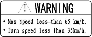
4 IMPORTANT NOTICE Curve speed must be smaller than 30km/h(19miles/h). This UTV is designed and manufactured OFF-ROAD use only. It is illegal and unsafe to operate this UTV on any public street, road or highway. This UTV complies with all applicable OFF-ROAD noise level and spark arrester laws and regulations in effect at the time of manufacture. Please check your local riding laws and regulations before operating this UTV. When the temperature is below -20 (-4 F), please park the UTV in the place where the temperature is higher than -20 (-4 F). After the UTV has warmed up, the UTV can be started. Please check page 6-2 on the warming up process. When the temperature is higher than 38 (100 F), and when you park the UTV after it run at high speed, please turn off the flameout switch firstly, while make the radiator fan still work for 1 minute, then turn off the power switch to save the battery. IMPORTANT NOTICE The 500/650 series UTV has the same methods for using, inspection, and maintenance. With the details of using, inspection and maintenance, the instruction is suitable for all 500/650 UTV.
5 CONTENTS 1 LOCATION OF THE WARNING 2 AND SPECIFICATION LABELS SAFETY INFORMATION DESCRIPTION AND VEHICLE IDENTIFICATION 3-1 Identification number records 3-3 Key identification number 3-4 Vehicle identification number 3-5 Model label CONTROL FUNCTIONS 4-1 Main switch 4-1 Indicator and warning lights 4-2 Multi-function meter unit 4-5 Switches 4-7 Accelerator pedal 4-12 Brake pedal 4-13 Parking brake lever 4-14 Drive select lever 4-14 Fuel tank cap 4-15 Seats 4-15 Seat belts 4-16 Glove compartment 4-19 Cargo bed 4-19 Front and rear shock absorber adjustment 4-22 Trailer hitch bracket 4-24 Auxiliary DC jack PRE-OPERATION CHECKS 5-1 Front and rear brakes 5-2 Fuel 5-4 Engine oil 5-5 Coolant 5-6 Final gear oil 5-7 Differential gear oil 5-7 Accelerator pedal 5-7 Seat belts 5-7 Steering 5-8 Fittings and fasteners 5-8 Lights 5-8 Switches 5-8
6 Tires 5-9 How to measure tire pressure 5-10 Tire wear limit OPERATION 6-1 Starting a cold engine 6-1 Starting a warm engine 6-3 Jump-starting 6-3 Warming up 6-5 Drive select lever operation and reverse driving 6-4 Engine brake-in 6-5 Parking 6-6 Parking on a slope 6-7 Accessories and loading DRIVING YOUR VEHICLE 7-1 Getting to know your vehicle 7-1 Learning to operate your vehicle 7-5 Turning your vehicle 7-6 Braking 7-7 Going uphill 7-7 Going downhill 7-9 Crossing through shallow water 7-11 Riding over rough terrain 7-13 Riding in brush or wooded areas 7-14 Encountering obstacles on the trail PERIODIC MAINTENANCE AND ADJUSTMENT 8-1 Owner s manual and tool kit 8-1 Periodic maintenance chart for The emission control system 8-4 General maintenance and lubrication chart 8-5 Hood 8-7 Console 8-9 Engine oil and oil filter cartridge 8-9 Final gear oil 8-14 Differential gear oil 8-16 Coolant 8-18 Axle boots 8-19 Spark plug inspection 8-20 Cleaning the air filter elements 8-23
7 V-belt cooling duct check hose 8-26 V-belt case drain plug 8-26 Cleaning the spark arrester 8-27 Front brake pad check 8-29 Rear brake pad check 8-29 Checking the brake fluid level 8-30 Brake fluid replacement 8-31 Checking the brake pedal 8-31 Parking brake lever free play adjustment 8-33 Brake light switch adjustment 8-34 Cable inspection and lubrication 8-35 Brake pedal and accelerator pedal lubrication 8-36 Rear knuckle upper and lower pivot lubrication 8-36 Steering shaft lubrication 8-37 Wheel removal 8-37 Wheel installation 8-37 Battery 8-38 Battery maintenance 8-40 Fuse replacement 8-41 Replacing a headlight bulb Headlight beam adjustment 8-45 Tail/brake light bulb replacement 8-46 Troubleshooting 8-49 Troubleshooting charts 8-49 CLEANING AND STORAGE 9-1 A. Cleaning 9-1 B. Storage 9-3 SPECIFICATIONS 10-1 NOLSE REGULATION 11-1 MAINTENANCE RECORD 12-1
8 LOCATION OF THE WARNING AND SPECIFICATION LABELS Read and understand all of the labels on your vehicle. They contain important 1-1

9 information for safe and proper operation of your vehicle. Never remove any labels from your vehicle. If a label becomes difficult to read or comes off, a replacement label is available from your dealer. 1-2

10 1-3


11 1-4
12 SAFETY INFORMATION This off-highway utility vehicle handles differently from other vehicles including cars and ATVs. SEVERE INJURY OR DEATH can result you do not follow these instructions: Read this manual and all labels carefully and follow the operating procedures described. This vehicle is designed to carry the diver and one passenger.never carry passengers in the cargo bed. Always be sure the driver and passenger are wearing seat belts. Never give a ride to a passenger who is too small to reach and hold the handgrip on the enclosure. Always avoid operating the vehicle on any paved surfaces, including sidewalks, driveways, parking lots, and streets. Never operate this vehicle on any public street, road, or highway, even a dirt or gravel one. Never operate this vehicle without wearing an approved motorcycle helmet that fits properly. You should also wear eye protection(goggles or a face shield), gloves, over-the-ankle boots, long-sleeved shirt or jacket, and long pants. Never consume alcohol or drugs before or while operating this vehicle. Never operate at speeds too fast for your skills or the conditions. Always go at a speed that is proper for the terrain, visibility, operating conditions, and your experience. Never attempt jumps of other stunts. Always inspect your vehicle each time you use it to be sure it is in safe operating condition, 2-1
13 Always follow the inspection and maintenance procedures and schedules described in this manual. Always keep both hands, arms, feet, and legs inside the vehicle at all times during operation. Keep your feet on the floorboard. Never hold onto the enclosure except when using the handgrip inside the enclosure. Otherwise, your hand could be injured if it is caught between the enclosure and an obstacle outside the vehicle. Always keep both hands on the steering wheel when driving. Never wrap your thumbs and fingers around the steering wheel. This is particularly important when driving in rough terrain. The front wheels will move right and left as they respond to the terrain, and this movement will be felt in the steering wheel. A sudden jolt could wrench the steering wheel around, and your thumbs or fingers could be injured if they are in the way of the steering wheel spokes. Always go slowly and be extra careful when operating on unfamiliar terrain.always be alert to changing terrain conditions when driving the vehicle. Never operate on excessively rough, slippery, or loose terrain until you have learned and practiced the skills necessary to control the vehicle on such terrain. Always be especially cautious on these kinds of terrain. Never turn at excessive speed. Practice turning at slow speeds before attempting to turn at faster speeds. Do not attempt turns on steep inclines. Never operate the vehicle on hills that are too steep for it or for your abilities. Go straight up and down hills where possible. Maximum slope angle:15 2-2
14 Never operate on hills that are slippery or ones where you will not be able to see far enough ahead of you. Never go over the top of a hill at speed if you cannot see what is on other side. Always follow proper procedures for going uphill. If you lose control and cannot continue up a hill, back down the hill with the engine in reverse gear. Use engine braking to help you go slowly. If necessary, use the brakes gradually to help you go slowly. Always check terrain before going down hills. Go as slowly ad possible. Never go down a hill at high speed. Always check for obstacles before operating in a new area. Never operate the vehicle in fast flowing water or water deeper than the floorboards on this model. Remember that wet brakes may have reduced stopping ability. Test your brakes after leaving water. If necessary, apply them several times to let friction dry out the linings. Always be sure there are no obstacles or people behind you when you operate in reverse. When it is safe to proceed in reverse, go slowly. Do not brake abruptly when carrying loads in the cargo bed. Always use the size and type of tires specified in this manual. Always maintain proper tire pressure as described in this manual. Never exceed the stated load capacity. Cargo should be as far forward in the bed as possible, and distributed evenly from side to side. Be sure cargo is secured so that it cannot move around during operation. Reduce speed and follow instructions in this manual for carrying cargo or pulling a trailer. Allow greater distance for braking. 2-3
15 WARNING POTENTIAL HAZARD Improper handling of gasoline. WHAT CAN HAPPEN Gasoline can catch fire and you could be burned. HOW TO AVOID THE HAZARD Always turn off the engine when refueling. Do not refuel right after the engine has been running and is still very hot. Do not spill gasoline on the engine or exhaust pipe/muffler when refueling. Never refuel while smoking, or while in the vicinity of sparks, open flames, or other sources of ignition such as the pilot light of water heaters and clothes dryers. When transporting the vehicle in anot- 2-4
16 2-5 her vehicle, be sure it is kept in an upright position. Otherwise, fuel may leak out of the carburetor or fuel tank. WHAT CAN HAPPEN Gasoline is poisonous and can cause injuries. HOW TO AVOID THE HAZARD If you should swallow some gasoline or inhale a lot of gasoline vapor, or get some gasoline in your eyes, see your doctor immediately. If gasoline spills on your skin, wash with soap and water. If gasoline spills on your clothing, change your clothes.
17 WARNING POTENTIAL HAZARD Starting or running the engine in a closed area. WHAT CAN HAPPEN Exhaust fumes are poisonous and may cause loss of consciousness and death within a short time. HOW TO AVOID THE HAZARD Always operate your vehicle in an area with adequate ventilation. 2-6


18 DESCRIPTION AND VEHICLE IDENTIFICATION 3-1
19 1. Headlights 2. Front shock absorber assembly adjusting ring 3. Brake fluid reservoir 4. Air filter element(engine and air intake duct) 5. V-belt case 6. Driver seat 7. Driver seat belt 8. Spark plug 9. Cargo bed 10. Tail/brake lights 11. Spark arrester 12. Rear shock absorber assembly adjusting ring 13. Cargo bed release levers 14. Fuel tank cap 15. Passenger seat belt 16. Passenger seat 17. Coolant reservoir 18. Oil filter cartridge 19. Engine oil dipstick 20. Battery 21. Fuses 22. Radiator cap 3-2

20 3-3
21 23. Low/High switch 24. Light switch 25. Emergency switch 26. Turn light switch 27. Ignition switch 28. Horn switch 29. Steering wheel 30. Main switch 31. Brake pedal 32. Accelerator pedal 33. Parking brake lever 34. On-Command four-wheel-drive and differential lock switches 35. Multi-function meter unit 36. Auxiliary DC jack 37. Drive select lever 38 Winch control connection NOTE: The vehicle you have purchased may differ slightly from those in the figures of this manual. Identification number records Record the key identification number, vehicle identification number and model label 3-4 information in spaces provided for assistance when ordering spare parts from a dealer or for reference in case the vehicle is stolen. 1.KEY IDENTIFICATION NUMBER:
22 2.VEHICLE IDENTIFICATION NUMBER: 3.MODEL LABEL INFORMATION Key identification number The key identification number is stamped on the key as shown in the following illustration, This number can be used for ordering a new key. 1. Key identification number Vehicle identification number The Vehicle identification number is stamped into the frame. 3-5


23 information will be needed to order spare parts from your dealer. 1. Vehicle identification number NOTE: The vehicle identification number is used to identify your vehicle 1. Model label Model label The model label is affixed to the frame under the driver seat. Record the information on this label in the space provided. This 3-6

24 CONTROL FUNCTIONS Main switch 1. Main switch Functions of the respective switch positions are as follows: ON: All electrical circuits are supplied with power, and the headlights and taillights come on when the light switch is on. OFF: All electrical circuits are switched off. The key can be removed in this position. START: The electric starter is engaged by turning and holding the key in this position. Release the key when the engine starts. 4-1
25 1 CAUTION: Do not operate the electric starter continuously for more than 5 seconds, or starter damage could occur. Wait at least 5 seconds between each operation of the electric starter to let it cool. Do not turn the key to the START position with the engine running, or damage to the electric starter can result. See starting instructions prior to starting the engine. (See pages for details.) 4-2 Indicator and warning lights 1. High-range indicator light H 2. Parking brake indicator light P 3. Low-range indicator light L 4. Four-wheel locked showing light 5. Neutral indicator light N 6. Reverse indicator light R 7. On-Command four-wheel-drive/differential gear lock indicator / 8. Coolant temperature warning light 9. Far light indicator 10. Position indicator 11. Emergency indicator On-Command differential gear lock indicator light DIFF. LOCK
26 On-Command differential gear lock indicator light DIFF. LOCK This indicator light and the On-Command differential gear lock indicator in the display come on when the On-command differential gear lock switch is set to the LOCK position. NOTE: When the switch is set to LOCK, the On-Command differential gear lock indicator light will flash until the differential gear is locked. Low-range indicator light L This indicator light comes on when the drive select lever is in the L position. High-range indicator light H This indicator light comes on when the drive select lever is in the H position. Neutral indicator light N This indicator light comes on when the drive select lever is in the N position. Reverse indicator light R This indicator light comes on when the drive select lever is in the R reverse position. Furthermore, this indicator light flashes when the engine is being raced for 10 seconds or more. NOTE: If the indicator light flashes under any other circumstances or the speedometer does not show the speed while riding, have a dealer check the speed sensor circuit. Parking brake indicator light P This indicator light comes on when the parking brake is applied. 4-3
27 On-Command four-wheel-drive/differential gear lock indicator / The On- Command four- wheel-drive indicator comes on when the On-Command four- wheel-drive switch is set to the 4WD position. The On-Command differential gear lock indicator in the On-Command four-wheeldrive indicator also comes on when the On-Command differential gear lock switch is set to the LOCK position. NOTE: Due to the synchronizing mechanism in the differential gear case, the four-wheeldrive indicator may not come on until the vehicle starts moving. When the on-command differential gear lock switch is set to LOCK, the indicator will flash until the differential gear is locked. Coolant temperature warning light When the coolant temperature reaches a specified level, this light comes on to warn that the coolant temperature is too hot, If the light comes on during operation, stop the engine as soon as it is safe to do so and allow the engine to cool down for about 15 minutes. (See page ) CAUTION: The engine may overheat if the vehicle is overloaded. If this happens, reduce the load to specification. After restarting, make sure that the light is out. Continuous use while the light is on may cause damage to the engine. 4-4

28 Multi-function meter unit 1. Speedometer 2. Turning speed demenstration 3. Clock/Hour button 4. Metrical/english system 5. Clock/Hour meter 6. Odometer/Tripmeter A / Tripmeter B 7. TRIP/ODO button 8. Left turning light indicator 9. Right turning light indicator The multi-function meter unit is equipped with the following: a speedometer (which shows the riding speed) an odometer (which shows the total distance traveled) two tripmeters (which show the distance traveled since they were last set to zero) a clock an hour meter (which shows the total time the key has been turned to ON ) a fuel meter Odometer and trip meter modes Pushing the TRIP/ODO button switches the display between the odometer mode ODO and the trip meter modes A and B in the following order: ODO TRIP A TRIP B ODO To reset a trip meter, select it by pushing the TRIP/ODO button, and then push the TRIP/ODO button for at least three seconds. The trip meters can be used to estimate the distance that can be traveled 4-5
29 with a full tank of fuel. This information will enable you to plan future fuel stops. NOTE: Holding in the TRIP/ODO button and then turning the key to ON switches the display between mph and km/h. Clock mode Pushing the button switches the display between the clock mode CLOCK and the hour meter mode HOUR in the following order: CLOCK HOUR CLOCK To set the clock 1. Set into the clock mode. 2. Press the watch button for 3-5 seconds. 3. Press the button of KM/MILE to set the hours. 4. Press the button of TRIP/000 to set the minutes. 4-6 Press the watch button for 3-5 seconds, and then release it, the clock will begin to work. Fuel meter The fuel meter will indicate the fuel volume. As the fuel is running out, the indicator will turn green into red, Vice versa. 1. Fuel level warning indicator 2. Fuel meter

30 Switches 1. Ignition switch 2. Low/High beam switch 3.Emergency light switch 4. Horn switch 5. Turn signal light switch 6. Light switch Ignition switch Set the switch to downward position before start the engine or change the switch to upward position to cut off the pulse signal. Light switch OFF/ / Set the switch to to turn on the low beam. Set the switch to to turn on the high beam. Emergency light switch Set the switch to upward position to turn on 4-7
31 all the head lights and taillights, All the lights will flash. Horn switch Pull down and hold the horn switch to start the horn. Turn signal light switch Set the switch to upward position to turn on the left signal lights and set the switch to downward position to turn on the right signal lights. Light switch Set the switch to middle position to turn on the head lights and taillights; set the switch to upward position to turn on the small lights. CAUTION: Do not use the headlights with the engine turned off for an extended period of time. The battery may discharge to the point that the starter motor will not operate properly. If this should happen, remove the battery and recharge it. On-Command four-wheel drive and diff- erential gear lock switches 1. On-Command four-wheel drive switch 2WD / 4 WD 2. Differential gear lock switch LOCK / 4WD This vehicle is equipped with an On-Com- mand four wheel-drive switch 2WD / 4WD and a differential gear lock switch 4WD / LOCK. Select the appropriate drive 4-8
32 according to terrain and the conditions. Two-wheel drive ( 2WD ): Power is supplied to the rear wheels only. Four-wheel drive ( 4WD ): Power is supplied to the rear and front wheels. Four wheel drive with the differential gear locked ( 4WD-LOCK ): Power is supplied to the rear and front wheels when the differential gear is locked ( DIFF.LOCK ).Unlike the 4WD mode, all wheels turn at the same speed regardless of traction. 4-9 WARNING POTENTIAL HAZARD Changing from 2WD to 4WD or from 4WD to 4WD-LOCK ( DIFF.LOCK ), or vice-versa while the vehicle is moving. WHAT CAN HAPPEN The vehicle handles differently in 2WD than in 4WD and in 4WD-LOCK in some circumstances. Changing from 2WD to 4WD or from 4WD to 4WD LOCK, or vice-versa while moving may cause the vehicle to unexpectedly handle differ- ently. This could distract the operator and increase the risk of losing control and an accident. HOW TO AVOID THE HAZARD Always stop the vehicle before chang- ing from 2WD to 4WD or from 4WDto 4WD LOCK, or vice-versa.
33 On-Command four-wheel-drive switch 2WD/4WD On-Command differential gear lock switch 4WD / LOCK 1. Select lever 2. On-Command four wheel-drive switch 2WD/4WD 1. On-Command differential gear lock switch 4WD / LOCK 2. Select lever To change from 2WD to 4WD,stop the To lock the differential gear in 4WD, stop the vehicle, and then set the switch to vehicle, make sure the On-Command four-wheel-drive switch is set to 4WD,move 4WD.When the vehicle is in 4WD, the the select lever to position,and then set 4WD indicator will come on in the the switch to LOCK. When the differential multi-function meter unit display.to change gear is locked, the differential gear lock from 4WD to 2WD.stop the vehicle,be sure indicator light ( DIFF. LOCK ) will come on the select lever is set to position, and along with the differential gear lock indicator then set the switch to 2WD. in the multifunction meter unit display.to release the differential gear lock, stop the 4-10
34 vehicle and set the switch to 4WD. WARNING POTENTIAL HAZARD Riding too fast while the vehicle is in 4WD-LOCK. WHAT CAN HAPPEN All wheels turn at the same speed when the differential is locked, so it takes more effort to turn the vehicle. The amount of effort required is greater the faster you go. You may lose control and have an accident if you cannot make a sharp enough turn for the speed you are traveling. HOW TO AVOID THE HAZARD Always ride at a slow speed when the vehicle is in 4WD-LOCK, and allow extra time and distance for maneuvers. NOTE: When the switch is set to LOCK, the differential gear lock indicator and indicator light will flash until the differential gear is locked. When the indicator and indicator light are flashing, turning the steering wheel back and forth will help the differential gear lock to engage. Riding before the differential gear lock is properly engaged (e.g.,when the indica- tor and indicator light are flashing)will cause the engine speed to be limited until engagement is complete. 4-11

35 Accelerator pedal Press the accelerator pedal down to increase engine speed. Spring pressure returns the pedal to the rest position when released. Always check that the accelerator pedal returns normally before staring the engine. 1.Accelerate pedal Before starting the engine, check the accelerate pedal to be sure it is operating smoothly. Make sure the accelerator pedal fully returns to the idle position as soon as it is released. WARNING POTENTIAL HAZARD Malfunction of the accelerator pedal. WHAT CAN HAPPEN The accelerator pedal could de hard to operate, making it difficult to speed up or slow down when you need to.this could cause an accident. HOW TO AVOID THE HAZARD Check the operation of the accelerator pedal before you start the engine.if it does not work smoothly, check for the cause. Correct the problem before operating the vehicle. Consult a dealer if you can t find or solve the problem yourself. 4-12
36 Brake pedal Press the brake pedal to slow or stop the vehicle. Parking brake lever The parking brake lever is located at the right side of the driver s seat. It will help hold the vehicle from moving while parked. To set the parking brake, pull the lever up completely. To release the parking brake, pull up on the lever, press the release button, and then push the lever all the way down. Spring pressure helps return the lever to the released position. Be sure to fully release the parking brake before starting out, Failure to do so may result in poor performance and premature wearing of the rear brake and V-belt. 1. Brake pedal 4-13


37 1. Parking brake lever 2. Release button 1. Drive select lever Drive select lever The drive select lever is used to shift you vehicle into the low, high, neutral and reverse positions. (Refer to pages for the drive select lever operation.) 4-14


38 Fuel tank cap Remove the fuel tank cap by turning it counterclockwise. Seats To remove a seat, pull its seat lock lever upward, lift the front of the seat, and then slide the seat forward and up. 1. Fuel tank cap 1. Seat lock lever ( 2) 4-15


39 To install a seat, insert the projection on the rear of the seat into the seat holders and push down on the seat at the front. WARNING POTENTIAL HAZARD A loose seat. WHAT CAN HAPPEN The operator could lose control or the operator or passenger could fall if the seat is loose during operation. HOW TO AVOID THE HAZARD Make sure the seat is securely latched. Seat belts This vehicle is equipped with three-point seat belts for both the operator and passenger. Always wear the seat belt while riding in the vehicle. 4-16

40 1. Seat belt ( 2) 2. Latch plate ( 2) 3. Buckle ( 2) To wear the seat belt properly, do the following: 1. Hold the latch plate as you pull the belt across your lap and chest. Make sure the belt is not twisted and is not caught on any portion of the vehicle, your clothing, or any equipment you are carrying. 2. Push the latch plate into the buckle until it clicks. Pull up on the latch plate to make sure it is secure Buckle 2. Latch plate 3. Put the lap portion of the belt low on your hips. Push down on the buckle end of the belt as you pull up on the shoulder part so the belt is snug across your hips. 4. Position the shoulder belt over your shoulder and across your chest. The shoulder belt should fit against your

41 chest. If it is loose, pull the belt out all the way and then let it retract. 5. To release the buckle, firmly press the release button. WARNING POTENTIAL HAZARD Not wearing the seat belt. Wearing the seat belt improperly. WHAT CAN HAPPEN There is increased risk of being killed or seriously injured in an accident. HOW TO AVOID THE HAZARD Always wear your seat belt when riding in the vehicle. Be sure the seat belt is close-fitting across your hips and chest and is latched securely. 1. Buckle 2. Release button 4-18


42 Glove compartment 1CAUTION: Cargo bed To protect from damage, do not put metal products, like tools or sharply edged products directly in the glove compartment. If they must be stored, wrap them in appropriate cushion material. 1. Cargo bed 2. Tailgate 4-19

43 Opening and closing the tailgate Lifting and lowering the cargo bed 1. Tailgate 2. Latch ( 2) To open Pull up the latches, and then lower the tailgate. To close Rotate the tailgate upward and place the tailgate in the original position. 1. Cargo bed release lever To lift Push down the cargo bed release lever To lower Lower the cargo bed slowly to its original position and be sure that it is locked into place. Maximum load limit:100kg (220lb) 4-20
44 WARNING POTENTIAL HAZARD Pinch points. WHAT CAN HAPPEN You or someone else could be pinched between the cargo bed and the frame when the bed is being lowered. HOW TO AVOID THE HAZARD Before closing the bed, be sure others are standing away from the vehicle. Keep hands and fingers away from the pinch points between the bed and the frame. WARNING POTENTIAL HAZARD Overloading the cargo bed WHAT CAN HAPPEN Could cause changes in vehicle handl- ing which could lead to an accident. HOW TO AVOID THE HAZARD Never exceed the stated maximum load limit for this cargo bed. Cargo should be properly distributed and securely attached. Reduce speed when carrying cargo. Al- low further distance for braking. 4-21
45 WARNING POTENTIAL HAZARD Carrying a passenger in the cargo bed WHAT CAN HAPPEN The passenger could fall, be thrown out, or be struck by objects in the cargo bed. HOW TO AVOID THE HAZARD Never carry a passenger in the cargo bed. This cargo bed is designed to carry cargo only. Front and rear shock absorber adjustment The spring preload can be adjusted to suit the operating conditions. You can reduce preload for a softer ride, or increase preload if frequent bottoming occurs 1CAUTION: Frequent or severe bottoming can cause increased wear or damage to the vehicle. Adjust the spring preload as follows. To increase the spring preload, turn the adjusting ring in direction. To decrease the spring preload, turn the adjusting ring in direction. 4-22
46 1. Spring preload adjusting ring 2. Position indicator NOTE: A special wrench can be obtained at a dealer to make this adjustment. 1. Special wrench Standard position: B A-Minimum(soft) E-Maximum(hard) 4-23

47 WARNING POTENTIAL HAZARD Improper shock absorber adjustment. WHAT CAN HAPPEN Uneven adjustment can cause poor handling and loss of stability, which could lead to an accident. HOW TO AVOID THE HAZARD Always adjust the shock absorbers on the left and right side to the same setting. Trailer hitch bracket This vehicle is equipped with a 5 cm (2 in) receiver bracket for a standard trailer hitch. Trailer towing equipment can be obtained at a dealer. (See pages for precaution information.) 4-24


48 Auxiliary DC jack The auxiliary DC jack is located at the right side of the front panel. The auxiliary DC jack can be used for suitable work lights, radios, etc. The auxiliary DC jack should only be used when the engine is running. 2. Start the engine. (See pages ) 3. Open the auxiliary DC jack cap, and then insert the accessory power plug into the jack. 1. Auxiliary DC jack 1. Auxiliary DC jack cap 1. Set the light switch to OFF. Maximum rated capacity for the auxiliary DC jack: DC 12V, 120W (10 A) 4. When the auxiliary DC jack is not being 4-25
49 used, cover it with the cap. 1CAUTION: Do not use accessories requiring more than the above maximum capacity. This may overload the circuit and cause the fuse to blow. If accessories are used without the engine running or with the headlights turned on, the battery will lose its charge and engine starting may become difficult. Do not use an automotive cigarette lighter or other access with a plug that gets hot because the jack can be damaged. 4-26
50 PRE-OPERATION CHECKS Before using this vehicle, check the following points: ITEM ROUTINE PAGE Check operation, free play, fluid level and fluid leakage. Brakes Fill with DOT 4 brake fluid if necessary , Parking brake Check for proper operation, condition and free play Check oil level. Fuel Fill with oil if necessary. Check oil level. Engine oil 5-5, Fill with oil if necessary. Check coolant level. Coolant reservoir 5-6, Fill with coolant if necessary. Final gear oil / Check for leakage. 5-7, Differential gear oil Accelerator pedal Check for proper accelerator pedal operation. 5-7 Seat belts Check for proper operation and belt wear. 5-7 Steering Check for proper operation. 5-8 Fittings and fasteners Check all fittings and fasteners. 5-8 Lights and switches Check for proper operation. 5-8, Wheels and tires Check tire pressure, wear and damage , Axle boots Check for damage
51 WARNING POTENTIAL HAZARD Failure to inspect the vehicle before operating. Failure to properly maintain the vehicle. WHAT CAN HAPPEN Increases the possibility of an accide- nt or equipment damage. HOW TO AVOID THE HAZARD Always inspect your vehicle each time you use it to make sure the vehicle is in safe operating condition. Always follow the inspection and maintenance procedures and schedules described in the Owner s Manual. Front and rear brakes Brake pedal Check for correct brake pedal free play. If the brake pedal free play is incorrect, have a dealer adjust it. (See pages 8-36.) Check the operation of the brake pedal. It should move smoothly and there should be a firm feeling when the brakes are applied. If not, have the vehicle inspected by a dealer. Brake fluid level Check the brake fluid level. Add fluid if necessary. (See pages ) Recommended brake fluid: DOT 4 5-2
52 Brake fluid leakage Check to see if any brake fluid is leaking out of the pipe joints or the brake fluid reservoir. Apply the brakes firmly for one minute. If there is any leakage, have the vehicle inspected by a dealer. Brake operation Test the brakes at slow speed after starting out to make sure they are working properly. If the brakes do not provide proper braking performance, inspect the brake system. (See pages ) WARNING POTENTIAL HAZARD Driving with improperly operating brakes. WHAT CAN HAPPEN You could lose braking ability, which could lead to an accident. HOW TO AVOID THE HAZARD Always check the brakes at the start of every ride. Do not operate the vehicle if you find any problem with the brakes. If a problem cannot be corrected by the adjustment procedures provided in this manual, have the vehicle inspected by a dealer. 5-3
53 Fuel Make sure there is sufficient gasoline in the tank. Recommended fuel: Unleaded gasoline only Fuel tank capacity: 30.0L (6.60lmp gal, 7.93US gal) 1CAUTION: Use only unleaded gasoline. The use of leaded gasoline will cause severe damage to internal engine parts, such as the valves and piston rings, as well as to the exhaust system. Your engine has been designed to use regular unleaded gasoline with a pump octane number ([R+M] /2) of 86 or higher, or research octane number of 91 or higher. If knocking or pinging occurs, use a different brand of gasoline or premium unleaded fuel. Unleaded fuel will give you longer spark plug life and reduced maintenance cost. Gasohol There are two types of gasohol; gasohol containing ethanol and that containing methanol. Gasohol containing ethanol can be used if ethanol content does not exceed 10%. Gasohol containing methanol is not recommended by because it may cause fuel system damage or vehicle performance problems. 5-4
54 WARNING POTENTIAL HAZARD Improper care when refueling. WHAT CAN HAPPEN Fuel can spill, which can cause a fire and severe injury. Fuel expands when it heats up. If the fuel tank is overfilled, fuel could spill out due to heat from the engine or the sun. HOW TO AVOID THE HAZARD Do not overfill the fuel tank. Be careful not to spill fuel, especially on the engine or exhaust pipe. Wipe up any spilled fuel immediately. Be sure the fuel tank cap is closed securely. Engine oil Make sure the engine oil is at the specified level. Add oil as necessary. (See pages ) 1CAUTION: In order to prevent clutch slippage (since the engine oil also lubricates the clutch), do not mix any chemical additives. Do not use oils with a diesel specification of CD or oils of a higher quality than specified. In addition, do not use oils labeled ENERGYCONSERVING II or higher. Make sure that no foreign material enters the crankcase. Recommended engine oil type and quantity: See page
55 Coolant Check the coolant level in the coolant reservoir when the engine is cold. (The coolant level will vary with engine temperature.) The coolant level is satisfactory if it is between the minimum and maximum level marks on the coolant reservoir. If the coolant level is at or below the minimum level mark, add additional coolant to bring the level up to maximum level mark. If coolant is not available, add distilled water. Change the coolant every two years. (See pages )for details.) 1CAUTION: Hard water or salt water is harmful to the engine. You may use soft water if you cannot get distilled water. WARNING POTENTIAL HAZARD Removing the radiator cap when the engine and radiator are still hot. WHAT CAN HAPPEN You could be burned by hot fluid and steam blown out under pressure. HOW TO AVOID THE HAZARD Wait for the engine to cool before removing the radiator cap. Always use a thick rag over the cap. Allow any remaining pressure to escape before completely removing the cap. Coolant reservoir capacity (up to the maximum level mark): 0.35L(0.31lmp qt, 0.37US qt) 5-6
56 Final gear oil Make sure the final gear oil is at the specified level. Add oil as necessary. (See pages for details.) Recommended oil: SAE 80 API GL-4 Hypoid gear oil If desired, an SAE 80W90 hypoid gear oil may be used for all conditions. NOTE: GL-4 is a quality and additive rating, GL-5 or GL-6 rated hypoid gear oils may also be used. Differential gear oil Make sure the differential gear oil is at the specified level. Add oil as necessary. (See pages for details.) Recommended oil: SAE 80 API GL-5 Hypoid gear oil Accelerator pedal Check to see that the accelerator pedal operates correctly. It must operate smoothly and fully spring back to the idle position when released. Have a dealer repair as necessary for proper operation. Seat belts Make sure that both seat belts are not frayed or damaged. The seat belt must move smoothly when pulled out and retract on its own when released. The latch plate should click securely into the buckle and release when the release button is pushed firmly. Wash off any dirt or mud which could affect operation. Have a dealer repair as necessary for proper operation. 5-7
57 Steering Park on level ground. Turn the steering wheel right and left. Check for excessive free play abnormal noises, or a rough feeling. Have a dealer repair as necessary for proper operation. Fittings and fasteners Always check the tightness of chassis fittings and fasteners before a ride. Take the vehicle to a dealer or refer to the Service Manual for correct tightening torque. Lights Check the headlights and tail/brake lights to make sure they are in working condition. Repair as necessary for proper operation. Switches Check the operation of all switches. Have a dealer repair as necessary for proper operation. Tires WARNING POTENTIAL HAZARD Operating this vehicle with improper tires, or with improper or uneven tire pressure. WHAT CAN HAPPEN Use of improper tires on this vehicle, or operation of this vehicle with improper or uneven tire pressure, may cause loss of control, increasing your risk of accident. HOW TO AVOID THE HAZARD? 1. The tires listed below have been approved by Motor Manufac turing corporation of America for this model. Other tire combinations are not recommended. Size Type Front PR Rear PR 5-8
58 3. Tire pressure below the minimum specified could cause the tire to dislodge from the rim under severe riding conditions. The following are minimums: Front 63 kpa (0.64kgf/cm 2,9psi) Rear 63 kpa (0.64kgf/cm 2,9psi) 2. The tires should be set to the recommended pressure: Recommended tire pressure Front 70kpa (0.7 kgf/cm 2,10psi) Rear 70kpa (0.7 kgf/cm 2,10psi) Check and adjust tire pressures when the tires are cold. Tire pressures must be equal on both sides. 4.Use no more than the following pressures when seating the tire beads. Front 250kpa (2.5kgf/cm 2,36psi) Rear 250kpa (2.5kgf/cm 2,36psi) Higher pressures may cause the tire to burst. Inflate the tires very slowly and carefully. Fast inflation could cause the tire to burst. 5-9
59 How to measure tire pressure Use the tire pressure gauge. NOTE: The tire pressure gauge is included as stan- dard equipment. Make two measurements of the tire pressure and use the second reading. Dust or dirt in the gauge could cause the first reading to be incorrect. tions: Front Rear Recommended pressure Minimum Maximum 70kpa 63kpa 77kpa (0.70kgf/ cm 2, (0.64kgf/ cm 2, (0.77kgf/ cm 2, 10pai) 9pai) 11pai) 70kpa 63kpa 77kpa (0.70kgf/ cm 2, (0.64kgf/ cm 2, (0.77kgf/ cm 2, 10pai) 9pai) 11pai) Set pressure with tires cold. Set tire pressures to the following specifica- 1. Tire pressure gauge Tire wear limit 5-10
60 When the tire groove decreases to 3 mm (0.12 in) due to wear, replace the tire. a. Tire wear limit 5-11
61 OPERATION WARNING POTENTIAL HAZARD Operating vehicle without being familiar with all controls. WHAT CAN HAPPEN Loss of control, which could cause an accident or injury. HOW TO AVOID THE HAZARD Read the Owner s Manual carefully. If there is a control or function you do not understand, ask your dealer. Starting a cold engine WARNING POTENTIAL HAZARD Freezing control cables in cold weather. WHAT CAN HAPPEN You could be unable to control the vehicle, which could lead to an accident or collision. HOW TO AVOID THE HAZARD When riding in cold weather, always make sure all control cables work smoothly before you begin riding Apply the brake. 2. Shift the drive select lever into the neutral position.
62 NOTE: When the drive select lever is in the neutral position, the neutral indicator light should come on. If the neutral indicator light does not come on, ask a dealer to inspect the electric circuit. The engine can be started in any gear if the brake is applied. However, it is recommended to shift into neutral before starting the engine. 3. With your foot off the accelerator pedal, start the engine by turning the key to START. NOTE: If the engine fails to start, release the key, and then try starting again. Wait a few seconds before the next attempt. Each cranking should be as short as possible to preserve battery energy. Do not crank the engine more than 5 seconds on each attempt. 6-2 CAUTION: See the Engine break-in section prior to operating the engine for the first time. Starting a warm engine To start a warm engine, refer to the Starting a cold engine section. The starter (choke) should not be used. Press the accelerator pedal slightly. Jump-starting Jump-starting the vehicle should be avoided. The battery should be removed and charged instead. However, if the vehicle must be jumpstarted, proceed as follows. 1. Turn the key to OFF. 2. Open the hood. (See pages for hood opening and closing procedures.) 3. Remove the battery compartment cover.

63 4. Using a charged 12V battery, connect the positive lead of the jumper cable to the positive terminal of the battery in the vehicle and the other end of the positive lead to the positive terminal of the charged battery. WARNING Do not connect the negative lead of the jumper cable to the negative terminal of the battery in the vehicle. Be especially careful not to: touch the positive lead of the jumper cable to the negative lead. reverse the polarity of the jumper cables when connecting to the batteries-battery explosion and/or serious damage to the electrical system may occur. 1. Jumper cable positive lead 2. Jumper cable negative lead 5. Connect the negative lead of the jumper cable to the negative terminal of the charged battery and the other end of the negative lead to an unpainted metal surface of the vehicle Start the engine. (Refer to Starting a cold engine on pages ) 7. After the engine starts, disconnect the negative lead of the jumper cable from the vehicle and charged battery, and then disconnect the positive lead of the jumper cable from the charged battery and the battery in the vehicle. 8. Install the battery compartment cover. 9. Close the hood.

64 Warming up To get maximum engine life, always warm up the engine before starting off. Never accelerate hard with a cold engine! To see whether or not the engine is warm, check if it responds to the throttle normally. Drive select lever operation and reverse driving 2. Apply the brakes, press the left button, then shift by moving the drive select lever along the shift guide. NOTE: Make sure that the drive select lever is completely shifted into position. 1CAUTION: Before shifting, you must stop the vehicle and take your foot off the accelerator pedal. Otherwise, the transmission may be damaged. Shifting: Neutral to High and High to Low 1. Stop the vehicle. Keep your foot off the accelerator pedal. 3. Release the brakes and press the accelerator pedal gradually. 6-4
65 NOTE: When in reverse, the reverse indicator light should be on. If the light does not come on, ask a dealer to inspect the reverse indicator light electrical circuit. Due to the synchronizing mechanism in the engine, the light may not come on until the vehicle starts moving. 4. Check behind for people or obstacles, then release the brake pedal. 5. Press the accelerator pedal gradually and continue to watch to the rear while backing. WARNING POTENTIAL HAZARD Improperly operating in reverse. WHAT CAN HAPPEN You could hit an obstacle or person behind you, resulting in serious injury. HOW TO AVOID THE HAZARD When you shift into reverse, make sure there are no obstacles or people behind you. When it is safe to proceed, go slowly. Engine break-in There is never a more important period in the life of your vehicle than the period between zero and 20 hours. For this reason, we ask that you carefully read the following material. Because the engine is brand new, you must not put an 6-5
66 excessive load on it for the first several hours of running. During the first 20 hours, the various parts in the engine wear and polish themselves to the correct operating clearances. During this period, prolonged full throttle operation or any condition which might result in excessive engine heating must be avoided. However, momentary (2-3 seconds maximum) full throttle operation under load does not harm the engine. Each full throttle acceleration sequence should be followed with a substantial rest period for the engine by cruising at lower r/min so the engine can rid itself of the temporary build up of heat. If any abnormality is noticed during this period, consult a dealer. throttle. Allow a cooling off period of five to ten minutes after every hour of operation. Vary the speed of the vehicle from time to time. Do not operate it at one set throttle position hours: Avoid prolonged operation above 3/4 throttle. Rev the vehicle freely but do not use full throttle at any time. After break-in: The vehicle can now be operated normally. Parking When parking, stop the engine and shift the drive select lever into the neutral position. Apply the parking brake to help prevent the vehicle from rolling hours: Avoid continuous operation above half 6-6
67 Parking on a slope 1. Bring the vehicle to a stop by applying the brakes. 2. Stop the engine. 3. With the brakes applied, set the parking brake. NOTE: Like many other vehicles, the parking brake acts on the rear wheels. For the parking brake to have the effect of braking all four wheels, shift to 4WD before stopping the engine. WARNING POTENTIAL HAZARD Parking on a hill or other incline. WHAT CAN HAPPEN The vehicle could roll out of control, increasing the chance of an accident. HOW TO AVOID THE HAZARD Avoid parking on hills or other inclines. If you must park on an incline, apply the parking brake, and block the front and rear wheels with rocks or other objects. Do not park the vehicle at all on hills that are so steep you could not walk up them easily. 6-7
68 Accessories and loading Accessories Accessories can affect the handing and control of your vehicle. Keep the following in mind when considering an accessory or operating a vehicle which has accessories. Choose only accessories designed for your vehicle. Your dealer has a variety of genuine accessories. Other accessories may also be available on the market. However, it is not possible for to test all non accessories, nor have any control over the quality or suitability of them. Choose a genuine accessory, or one that is equivalent in design and quality. Accessories should be rigidly and securely mounted. An accessory which can shift position or come off while you are operating could affect your ability to control the vehicle. Do not mount an accessory where it could interfere with your ability to control the vehicle. Examples include (but are not limited to) an object that limits your ability to turn the steering wheel or one that limits your view. Use extra caution when driving a vehicle with accessories. The vehicle may handle differently than it does without accessories. Loading Cargo or a trailer can change the stability and handling of a vehicle. You must use common sense and good judgment when carrying cargo or towing a trailer. Keep the following points in mind: Never exceed the weight limits shown. An overloaded vehicle can be unstable. 6-8
69 MAXIMUM LOADING LIMIT Vehicle loading limit (total weight of cargo, operator, passenger and accessories, and tongue weight): 400Kg (880 lb) Cargo bed:100kg (220 lb) Trailer hitch: Pulling load (total weight of trailer and cargo):550kgf (1,212lbf) Tongue weight (vertical weight on trailer hitch point):50kgf (110lbf) Choose a trailer hitch drawbar designed for use with a 5 cm (2in) receiver.(see page 4-25 for more information) Do not exceed the maximum tongue weight. You can measure tongue weight with a bathroom scale. Put the tongue of the loaded trailer on the scale with the tongue at hitch height. Adjust the load in the trailer, if necessary, to reduce the 6-9 weight on hitch. If you are carrying cargo and towing a trailer, include the tongue weight in the maximum vehicle load limit. Load cargo in the cargo bed as close to the center of the vehicle as possible and tie it down using the cargo hooks equipped on the cargo bed. Tie down cargo securely in the trailer. Make sure cargo in the trailer cannot move around. A shifting load can cause an accident. Make sure the load does not interfere with controls or your ability to see where you are going. Drive more slowly than would without a load. The more weight you carry, the slower you should go. Although conditions vary, it is good practice not to exceed low range whenever you are
70 carrying heavier loads or when towing a trailer. Allow more braking distance. A heavier vehicle takes longer distance to stop. Avoid making sharp turns unless at very slow speeds. Avoid hills and rough terrain. Choose terrain carefully. Added weight affects the stability and handling of the vehicle. WARNING POTENTIAL HAZARD Overloading this vehicle or carrying or towing cargo improperly. WHAT CAN HAPPEN Could cause changes in vehicle handling which could lead to an accident. HOW TO AVOID THE HAZARD Never exceed the stated load capacity for this vehicle. Cargo should be properly distributed and securely attached. Reduce speed when carrying cargo or pulling a trailer. Allow greater distance for braking. 6-10
71 DRIVING YOUR VEHICLE GETTING TO KNOW YOUR VEHICLE This off-highway utility vehicle will handle and maneuver differently form an ordinary passenger car or other vehicle. Before you begin to use your vehicle, be sure you have read this Owner, s Manual completely and understand of the controls. Pay particular attention to the safety information on pages Please also read all caution and warning labels on your vehicle. This vehicle is designed for the operator and one passenger. The driver and passenger must always wear a seat belt. Never carry passengers in the cargo bed. WARNING POTENTIAL HAZARD Not wearing the seat belt. Wearing the seat belt improperly. WHAT CAN HAPPEN There is increased risk of being killed or seriously injured in an accident. HOW TO AVOID THE HAZARD Always wear your seat belt when riding in the vehicle. Be sure the seat belt is close-fitting across your hips and chest and is latched securely. 7-1

72 WARNING POTENTIAL HAZARD Carrying a passenger in the cargo bed. WHAT CAN HAPPEN The passenger could fall or be struck by objects in the cargo bed. HOW TO AVOID THE HAZARD Never carry a passenger in the cargo bed. The cargo bed is designed to carry cargo only. The total weight of operator, passenger, accessories, cargo, trailer tongue weight, and the vehicle itself must not exceed 943Kg (2,000 lb). (See Loading on page 6-11.) Carrying a passenger and cargo can affect vehicle handling. 7-2
73 WARNING POTENTIAL HAZARD Overloading this vehicle or carrying or towing cargo improperly. WHAT CAN HAPPEN Could cause changes in vehicle handling which could lead to an accident. HOW TO AVOID THE HAZARD Never exceed the stated load capacity for this vehicle. Cargo should be properly distributed and securely attached. Reduce speed when carrying cargo or pulling a trailer. Allow greater distance for braking. Always follow the instructions in your Owner s Manual for carrying cargo or pulling a trailer. The driver and passenger must always wear a seat belt and an approved motorcycle helmet. Also wear eye protection and protective clothing, including over-the-ankle boots, gloves, a long-sleeved shirt or jacket, and long pants. Keep hands and feet inside the vehicle at all times. 7-3

74 WARNING POTENTIAL HAZARD Operating this vehicle without wearing an approved motorcycle helmet, eye protection, and protective clothing. WHAT CAN HAPPEN Operating without an approved motorcycle helmet increases your chances of a severe head injury or death in the event of an accident. Operating without eye protection can result in an accident and increases your chances of a severe injury in the event of an accident. HOW TO AVOID THE HAZARD Always wear an approved motorcycle helmet that fits properly. You should also wear: eye protection (goggles or face shield) gloves boots long-sleeved shirt or jacket long pants 7-4
75 LEARNING TO OPERATE YOUR VEHICLE You should become familiar with the performance characteristics of the vehicle in a large, flat area that is free of obstacles and other vehicles. Practice control of the accelerator pedal, brakes, steering, and drive select lever. Drive first at slow speed and become comfortable at that speed before gradually increasing your speed. Become familiar with the way the vehicle feels in low and high ranges, first in two-wheel drive (2WD) and then in four-wheel drive (4WD) and four-wheel drive with the differential locked (DIFF. LOCK). Also practice driving in reverse. Take the time to learn basic operation before attempting more difficult maneuvers. Perform the Pre-Operation Checks on pages Set the parking brake, shift to neutral, and follow the instructions on page 6-1 to start the engine. Once it has warmed up and you have turned the choke off, you are ready to begin driving your vehicle. With the engine idling, shift the drive select lever into low or high. Then release the parking brake. Press the accelerator pedal slowly and smoothly. The centrifugal clutch will engage and you will start to accelerate. Avoid higher speeds until you are thoroughly familiar with the operation of your vehicle. When slowing down or stopping, take your foot off the accelerator pedal and smoothly press the brake pedal. Improper use of the brakes can cause the tires to lose traction, reducing control and increasing the possibility of an accident. 7-5
 than four-wheel drive (4WD). Steering takes the most effort in 4WD with the differential locked (DIFF.LOCK).")
76 1CAUTION: Do not shift from low to high or vice versa without coming to a complete stop and waiting for the engine to return to normal idle speed. Damage to the engine or drive train may occur. TURNING YOUR VEHICLE The vehicle is easier to steer in two-wheel drive (2WD) than four-wheel drive (4WD). Steering takes the most effort in 4WD with the differential locked (DIFF.LOCK). It is possible for the vehicle to roll over or go out of control if you attempt sharp, high-speed turns. You should also be careful making sharp turns on rough terrain. Do not attempt to turn around or make abrupt maneuvers on slope. Position your hands on the steering wheel so that your thumbs and fingers do not wrap around the wheel. This is particularly important when driving in rough terrain. The front wheels will move right and left as they respond to the terrain, and this movement will be felt in the steering wheel. A sudden jolt could wrench the steering wheel around, and your thumbs or fingers could be injured if they are in the way of the steering wheel spokes. 7-6
77 BRAKING Braking ability is affected by the type of terrain. In most cases, gradually application of the brakes is more effective than abrupt braking, particularly on loose surfaces like gravel. Always allow for greater braking distance on rough, loose, or slippery surfaces. GOING UPHILL Do not attempt to climb hills until you have mastered basic maneuvers on flat ground. Use proper driving techniques to avoid overturns on hills and slopes. Drive straight up hills, and avoid crossing the side of a hill, which increases your chance of rollover. Practice first on gentle slopes before attempting steeper hills. Always check the terrain carefully before attempting any hill. Use common sense and remember that some hills are too steep for you to climb. Choose carefully which hills you attempt to climb. Avoid hills with slippery surfaces or ones where you will not be able to see far enough ahead of you. Maximum slope angle:15 7-7
78 WARNING POTENTIAL HAZARD Operating on excessively steep hills. WHAT CAN HAPPEN The vehicle can over turn more easily on extremely steep hills than on level surfaces or small hills. HOW TO AVOID THE HAZARD Never operate your vehicle on hills too steep for it or your abilities. Never operate vehicles on hills steeper than 15. Do not drive across the face of a hill. Go straight up the hill. Practice on smaller hills before attempting large hills. Before climbing the hill, first be sure you are operating in low range 4WD or, if necessary, with 4WD Diff. Lock. To climb a hill, you need traction, momentum, and steady throttle. Travel fast enough to keep your momentum going, but not so fast that you cannot react to changes in the terrain as you climb. Slow down when you reach the crest of the hill if you cannot clearly see what is on the other side-there could be another person, an obstacle, or a sharp drop off. 7-8
79 If you start to lose traction or momentum when climbing, and you decide you will be unable to continue, use the brakes to come to a stop. Do not attempt to turn the vehicle around. With your foot on the brake, look behind you and plan your descent. Shift the drive select lever in reverse so you can use the engine brake if necessary to slow your descent. Release the brake and begin to coast down the hill. Use engine braking as much as possible, gently applying the brakes when necessary. GOING DOWNHILL Check the terrain carefully before going down a hill. When possible, choose a path that lets you drive your vehicle straight downhill. Avoid sharp angles that could allow the vehicle to pitch or roll over. Carefully choose your path and drive no faster than you will be able to react to obstacles that may appear. 7-9
80 WARNING POTENTIAL HAZARD Going down a hill improperly. WHAT CAN HAPPEN Could cause loss of control or cause the vehicle to overturn. HOW TO AVOID THE HAZARD Always check the terrain carefully before you start down any hill. Never go down a hill at high speed. Avoid going down a hill at an angle that would cause the vehicle to lean sharply to one side. Go straight down the hill where possible. Before starting down hill, make sure the vehicle is in low-range 4WD. On most slopes, this will let you use engine braking to help you go downhill slowly. Go as slowly as possible. If you are starting to go too fast, apply the brake gently. Avoid sudden application of the brakes, which could cause the vehicle to start sliding. If you are sliding or skidding, try to steer in the direction the vehicle is sliding to help you regain control. If you must turn on the hill to avoid an obstacle, do so slowly an carefully. if the vehicle starts to tip, gradually steer in the downhill direction if there are no obstacles in your path. As you regain proper balance, gradually steer again in the direction you want to go. 7-10
81 CROSSING THROUGH SHALLOW WATER If you must cross shallow, slow moving water up to the depth of the vehicle s floorboards, choose your path carefully to avoid sharp drop-offs, large rocks, or slippery surfaces that could cause the vehicle to overturn. Never operate through water deeper than 33 cm (13in) or fast flowing water. Wet brakes may have reduced effectiveness. After leaving the water, test your brakes. If necessary, apply the brakes several times to let friction dry out the linings. WARNING POTENTIAL HAZARD Operating this vehicle through deep or fast-flowing water. WHAT CAN HAPPEN Loss of control, which could result in an accident including overturn, which could increase the risk of drowning. HOW TO AVOID THE HAZARD Never operate this vehicle in fast flowing water or in water deeper than 33cm (13in). Remember that wet brakes may have reduced stopping ability. Test your brakes after leaving water. If necessary, apply them several times to let friction dry out the linings. 7-11

82 1CAUTION: After riding your vehicle in water, be sure to drain the trapped water by removing the check hose at the bottom of the air filter case, the V-belt cooling duct check hose, the drive select lever box check hose and the V-belt case drain plug. Wash the vehicle in fresh water if it has been operated in salt water or muddy conditions. 1.Air filter case check hose 1.V-belt cooling duct check hose 7-12

83 1. Drive select lever box check hose 1.V-belt case drain plug RIDING OVER ROUGH TERRAIN Operating over rough terrain should be done with caution. Look for obstacles that could cause damage to the vehicle or could lead to a rollover accident. Avoid jumping the vehicle as injury, loss of control, and damage to the vehicle could occur. 7-13

84 WARNING POTENTIAL HAZARD Failure to use extra care when operating this vehicle on unfamiliar terrain. WHAT CAN HAPPEN You can come upon hidden rocks, bumps, or holes, without enough time to react. Could result in the vehicle overturning or going out of control. HOW TO AVOID THE HAZARD Go slowly and be extra careful when operating on unfamiliar terrain. Always be alert to changing terrain conditions when operating the vehicle. 7-14
85 RIDING IN BRUSH OR WOODED AREAS When operating in areas with brush or trees, watch carefully on both sides and above the vehicle for obstacles such as branches that the vehicle might hit, causing an accident, or for brush that might enter the vehicle as you pass and strike the driver or passenger. Never hold onto the enclosure so your hand is outside the vehicle. Hold only onto the handgrip inside the enclosure. ENCOUNTERING OBSTACLES ON THE TRAIL If you cannot go around an obstacle such as a fallen tree trunk or a ditch,stop the vehicle where it is safe to do so.set the parking brake and get out to inspect the area thoroughly.look from both your approach side and the exit side.if you believe you can continue safely,decide the path that will allow you to get over the obstacle at as close to a right angle as possible to minimize vehicle tipping.go only fast enough to maintain your momentum but still give yourself plenty of time to react to changes in conditions.if there is any question about your ability to maneuver safely over the obstacle,you should turn around,if the ground is flat and you have the room,or back up until you find a less difficult path. 7-15
86 WARNING POTENTIAL HAZARD Improperly operating over obstacles. WHAT CAN HAPPEN Could cause loss of control or a collision. Could cause the vehicle to overturn. HOW TO AVOID THE HAZARD Before operating in a new area, check for obstacles. Use extreme caution when operating over large obstacles, such as large rocks or fallen trees. 7-16
87 PERIODIC MAINTENANCE AND ADJUSTMENT Periodic inspection, adjustment and lubrication will keep your vehicle in the safest and most efficient condition possible. Safety is an obligation of the vehicle owner. The most important points of vehicle inspection, adjustment and lubrication are explained on the following pages. WARNING POTENTIAL HAZARD Servicing an engine while it is running. WHAT CAN HAPPEN Moving parts can catch clothing or parts of the body, causing injury. Electrical components can cause shocks or can start fires. HOW TO AVOID THE HAZARD Turn off the engine when performing maintenance unless otherwise specified. Have a dealer perform service if you are not familiar with vehicle service. 8-1
88 1. Owner s tool kit 2. Tire pressure gauge The service information included in this manual is intended to provide you, the owner, with the necessary information for completing your own preventive maintenance and minor repairs. The tools provided in the Owner s tool kit are sufficient for this purpose, except that a torque wrench is also necessary to properly tighten nuts and bolts. NOTE: If you do not have a torque wrench available during a service operation requiring one, take your vehicle to dealer to check the torque settings and adjust them as necessary. 8-2
89 WARNING POTENTIAL HAZARD Operating this vehicle with improper modifications. WHAT CAN HAPPEN Improper installation of accessories or modification of this vehicle may cause changes in handling which in some situations could lead to an accident. HOW TO AVOID THE HAZARD Never modify this vehicle through improper installation or use of accessories. All parts and accessories added to this vehicle should be genuine or equivalent components designed for use on this vehicle and should be installed and used according to instructions. If you have questions, consult an authorized vehicle dealer. 8-3
90 Periodic maintenance chart for the emission control system NOTE: For vehicles not equipped with an odometer or hour meter, follow the month maintenance intervals. For vehicles equipped with an odometer or an hour meter, follow the km(mi) or hours maintenance intervals. However, keep in mind that if the vehicle isn t used for a long period of time, the month maintenance intervals should be followed. Items marked with an asterisk should be performed by dealer as they require special tools, data and technical skills. INITIAL EVERY Whichever Month ITEM ROUTINE Comes first Km 320 1,200 2,400 2,400 4,800 (mi) (200) (750) (1,500) (1,500) (3,000) hours Fuel line* Check fuel hose for cracks or damage. Replace if necessary. Valves* Check valve clearance. Adjust if necessary. Spark plug Check condition. Adjust gap and clean. Replace if necessary. Carburetor* Check idle speed/starter operation. Adjust if necessary. Crankcase breather Check breather hose for cracks or damage. system* Replace if necessary. Check for leakage. Exhaust system* Tighten if necessary. Replace gasket(s) if necessary. Spark arrester Clean. Sensor Clean. to clean for each 500km (312ml) 8-4
91 General maintenance and lubrication chart ITEM Cooling system Air filter elements (engine and air intake duct) ROUTINE Whichever Comes first Check coolant leakage. Repair if necessary. Replace coolant every 24 months. Clean. Replace if necessary. 8-5 INITIAL EVERY Month Km (mi) 320 (200) 1,200 (750) 2,400 (1,500) 2,400 (1,500) 4,800 (3,000) hours Every hours (More often in wet or dusty areas.) Engine oil Replace (warm engine before draining.) Engine oil filter cartridge Replace Final gear oil Differential gear oil Check oil lever oil leakage. Replace. Front brake* Check operation/brake pad wear/fluid leakage/see page 8-6. COrrect if necessary. Replace pads if worn to the limit. Rear brake* Check operation/brake pad wear/fluid leakage/see NOTE page 8-6. Correct if necessary. Replace pads if worn to the limit. Accelerator pedal* Check operation and free play. V-belt* Check operation. Check for wear, cracks, or damage. Wheels* Check balance/damage/runout. Replace if necessary. Check bearing assemblies for looseness/damaged. Wheel bearings* Repair if damaged. Front and rear suspension* Check operation and for leakage. Check toe-in/adjust if necessary.
92 ITEM Steering system* Rear upper and lower knuckle pivots* ROUTINE Whichever Comes first Check operation and for looseness/replace if damaged. Check toe-in/adjust if necessary INITIAL EVERY Month Km (mi) 320 (200) 1,200 (750) 2,400 (1,500) 2,400 (1,500) 4,800 (3,000) hours Lubricate with lithium soap-based grease. Drive shaft universal joint* Lubricate with lithium-soap-based grease. Engine mount* Front and rear axle boots* Check for cracks or damage. Check bolt tightness. Check operation. Replace if damaged. Stabilizer bushings* Check for cracks or damage. Fittings and fasteners* NOTE: Recommended brake fluld:dot4 Brake fluid replacement. Check all chassis fittings and fasteners. Check if necessary. When disassembling the master cylinder or caliper, replace the brake fluid. Normality check the brake fluid level and add fluid as required. On the inner parts of the master cylinder and caliper, replace the oil seals every two years. Replace the brake hoses every four years, or if cracked or damaged. 8-6

93 Hood To open Unhook the hood latches, and then slowly tilt the hood up until it stops. 1. Hood 1. Latch( 2) 8-7
94 To close Lower the hood slowly to its original position, and then hook the hood latches. Secure projections 1on the underside of the hood into slots 2 on the back of the instrument panel. Secure slots 3on the side of the hood around projections 4 on the frame. 1CAUTION: Make sure that all cables and wires are in place when closing the hood. Do not drive the vehicle with the hood open, unlatched, or removed. 1. Projection ( 2) 2. Slot ( 2) 3. Slot ( 2) 4. Projection ( 2) 8-8
95 Console To remove 1. Remove the seats. (See pages for seat removal and installation procedures.) 2. Pull up the parking brake lever. 3. Pull the console upward (the drive select lever boot will come loose.) To install 1. Place the console in its original position. 2. Pull down the parking brake lever. 3. Install the seats. 1CAUTION: When installing the console, be sure not to pinch the cables or wires. Make sure that the drive select lever boot fits securely around the edge of the hole in the console. 1. Console 8-9 Engine oil and oil filter cartridge The engine oil level should be checked before each operation. In addition, the oil
 3. Check the engine oil level on a cold engine.")
96 must be changed and the oil filter cartridge replaced at the intervals specified in the periodic maintenance and lubrication chart. To check the engine oil level 1. Place the vehicle on a level surface. 2. Remove the console. (See page 8-9 for console removal and installation procedures.) 3. Check the engine oil level on a cold engine. NOTE: If the engine was started before checking the oil level, be sure to warm up the engine sufficiently, and then wait at least ten minutes until the oil settles for an accurate reading. 4. Remove the engine oil filler cap and wipe off the dipstick with a clean rag. 5. Insert the dipstick in the oil filler hole (without screwing it in), and then remove it again to check the oil level NOTE: The engine oil should be between the minimum and maximum level marks. 1. Maximum level mark 2. Minimum level mark 3. Dipstick 4. Engine oil filler cap 6. If the engine oil is at or below the minimum level mark, add sufficient oil of the recommended type to raise it to the correct level. 7. Insert the dipstick into the oil filler hole, and then tighten the oil filler cap.

97 8. Install the console. To change the engine oil (with or without oil filter cartridge replacement) 1. Remove the console. (See page 8-9 for console removal and installation procedures.) 2. Place an oil pan under the engine to collect the used oil, and then remove the engine oil filler cap. 3. Remove the engine oil drain bolt to drain the oil from the crankcase. 1. Engine oil drain bolt NOTE: Skip steps 4-6 if the oil filter cartridge is not being replaced. 4. Remove the oil filter cartridge with an oil filter wrench Oil filter cartridge 2. Oil filter wrench NOTE: An oil filter wrench is available at a nearby
 1. Oil filler cartridge 2. Torque wrench 7. Install the engine oil drain bolt, and then tighten it to the specified torque. 1. O-ring 6.")
98 dealer. 5. Apply a light coat of engine oil to the O-ring of the new oil filter cartridge. NOTE: Make sure the O-ring is seated properly. Tightening torque: Oil filter cartridge: 17Nm (1.7m kgf, 12 ft lbf) 1. Oil filler cartridge 2. Torque wrench 7. Install the engine oil drain bolt, and then tighten it to the specified torque. 1. O-ring 6. Install the new oil filter cartridge with an oil filter wrench, and then tighten it to the specified torque with a torque wrench. Tightening torque: Engine oil drain bolt: 30Nm (3.0m kgf, 22 ft lbf) 8. Add the specified amount of recomm- 8-12
99 ended engine oil, and then install the engine oil filler cap and tighten it. Recommended engine oil: See page Oil quantity: Without oil filter cartridge replacement: 1.9 L (1.67 lmp qt, 2.01 US qt) With oil filter cartridge replacement: 2.0 L (1.76 lmp qt, 2.11 US qt) 1CAUTION: In order to prevent clutch slippage (since the engine oil also lubricates the clutch), do not mix any chemical additives. Do not use oils with a diesel specification of CD or oils of a higher quality than specified. In addition, do not use oils labeled ENERGY CONSERVING II or higher. Make sure that no foreign material enters the crankcase. 9. Start the engine, and then let it idle for several minutes while checking it for oil leakage. If oil is leaking, immediately turn the engine off and check for the cause. 10. Turn the engine off, wait at least ten minutes, and then check the oil level and correct it if necessary. 11. Install the console. 8-13
100 hole. Final gear oil Checking the final gear oil level 1. Place the vehicle on a level surface. 2. Remove the oil filler bolt, and then check the oil level in the final gear case. 3. If the oil is below the brim of the filler hole, add sufficient oil of the recommended type to raise it to the correct level. 1CAUTION: 1. Be sure no foreign material enters the final gear case. 2. Please clean the sensor every 500km period 4. Install the oil filler bolt, and then tighten it to the specified torque. 1. Speedometer sensor 2. final gear oil 3. Correct oil level NOTE: The oil level should be at the brim of the filler 8-14 Tightening torque: Final gear oil filler bolt: 23 Nm (2.3 m kgf, 17 ft lbf)
 5.")
101 Changing the final gear oil 1. Place the vehicle on a level surface. 2. Place a container under the final gear case to collect the used oil. 3. Remove the oil filler bolt and the drain bolt to drain the oil. Tightening torque: Final gear oil drain bolt: 20 Nm (2.0 m kgf, 14 ft lbf ) 5. Add the recommended final gear oil up to the brim of the filler hole. Recommended oil: SAE 80 API GL-4Hypoid gear oil Oil quantity: 0.25 L (0.22 lmp qt, 0.26 US qt) 1CAUTION: Be sure no foreign material enters the final gear case. 6. Install the oil filler bolt, and then tighten it to the specified torque. 1. Final gear oil drain bolt 4. Install the drain bolt, and then tighten it to the specified torque. Tightening torque: Final gear oil filler bolt: 23 Nm (2.3 m kgf, 17 ft lbf) 8-15
102 7. Check for oil leakage. If oil leakage is found, check for the cause. Differential gear oil Checking the differential gear oil level 1. Place the vehicle on a level surface. 2. Remove the differential gear oil filler bolt and check the oil level. It should be up to the brim of the filler hole. If the level is low, add sufficient oil of the recommended type to raise it to the specified level. 1. Differential gear oil filler bolt 2. Correct oil level 3. Differential gear oil 1CAUTION: Be sure no foreign material enters the differential gear case. 3. Install the differential gear oil filler bolt, and then tighten it to the specified orque. 8-16

103 Tightening torque: Differential gear oil filler bolt: 23Nm (2.3 m kgf, 17 ft lbf) Changing the differential gear oil 1. Place the vehicle on a level surface. 2. Place a container under the differential gear case to collect the used oil. 3. Remove the differential gear oil filler bolt and differential gear oil drain bolt to drain the oil 1. Differential gear oil drain bolt 4. Install the differential gear oil drain bolt, and tighten it to the specified torque. Tightening torque: Differential gear oil drain bolt: 9.8Nm (0.98 m kgf, 7.1 ft lbf) 5. Fill the differential gear case with the recommended oil Recommended oil: SAE 80 API GL-5 Hypoid gear oil Oil quantity: 0.32 L (0.28 lmp qt, 0.34 US qt) 1CAUTION: Be sure no foreign material enters the differential gear case. 6. Install the differential gear oil filler bolt,

104 and then tighten it to the specified torque. Tightening torque: Differential gear oil filler bolt: 23Nm (2.3m kgf, 17 ft lbf) NOTE: The coolant should be between the minimum and maximum level marks. 7. Check for oil leakage. If oil leakage is found, check for the cause. Coolant The coolant level should be checked before each ride. Checking the coolant level 1. Place the vehicle on a level surface. 2. Open the hood. (See pages for hood opening and closing procedures.) 3. Check the coolant level in the coolant reservoir when the engine is cold as the coolant level varies with engine temperature Coolant reservoir cap 2. Maximum level mark 3. Minimum level mark 4. If the coolant is at or below the minimum level mark, remove the reservoir cap,
 1CAUTION: Mix anti freeze with distilled water only. However, if distilled water is not available, soft water may be used for refilling.")
105 add coolant to the maximum level mark, install the reservoir cap, and then close the hood. Coolant reservoir capacity (up to the maximum level mark): 0.35L (0.31 lmp qt, 0.37 US qt) 1CAUTION: Mix anti freeze with distilled water only. However, if distilled water is not available, soft water may be used for refilling. Changing the coolant The coolant must be changed by a dealer at the intervals specified in the periodic maintenance and lubrication chart. NOTE: Adding water instead of coolant lowers the antifreeze content of the coolant. If water is used instead of coolant, have a dealer check the antifreeze content of the coolant as soon as possible. The radiator fan is automatically switched on or off according to the coolant temperature in the radiator. If your vehicle overheats, see page 8-49 for details. Axle boots Check the protective boots for holes or tears. If any damage is found, have them replaced by a dealer. 1. Front axle boot ( 2 each side) 8-19

 2. Remove the spark plug cap.")
106 Spark plug inspection Removal 1. Lift the cargo bed up. (See pages for cargo bed lifting and lowering procedures.) 2. Remove the spark plug cap. 1. Rear axle boot ( 2 each side) 1. Spark plug cap 8-20

107 3. Use the spark plug wrench in the tool kit to remove the spark plug as shown. 1. Spark plug wrench Inspection The spark plug is an important engine component and is easy to inspect. The condition of the spark plug can indicate the condition of the engine. The ideal color of the porcelain insulator around the center electrode is a medium-to-light tan for a vehicle that is being ridden normally. Do not attempt to diagnose such problems yourself. Instead, take the vehicle to a dealer. You should periodically remove and inspect the spark plug because heat and deposits will cause the spark plug to slowly break down and erode. If electrode erosion becomes excessive, or if carbon and other deposits are excessive, you should replace the spark plug with the specified plug. Specified spark plug: DCPR7E(NGK) 8-21
108 Installation 1. Measure the electrode gap with a wire thickness gauge and, if necessary, adjust the gap to specification. Spark plug gap: mm( in) 3. Install the spark plug and tighten it to the specified torque. Tightening torque: Spark plug: 17.5 Nm(1.75 m kgf, 12.7 ft lbf) NOTE: If a torque wrench is not available when you are installing the spark plug, a good estimate of the correct torque is 1/4 to 1/2 turn past finger tight. Have the spark plug tightened to the specified torque as soon as possible. 4. Install the spark plug cap. 5. Lower the cargo bed. a. Spark plug gap 2. Clean the surface of the spark plug gasket and its mating surface, and then wipe off any grime from the spark plug threads. 8-22

109 Cleaning the engine air filter element NOTE: There is a check hose at the bottom of the air filter case. If dust or water collects in this hose, empty the hose and clean the air filter element and air filter case. Remove the seats. (See pages for seat removal and installation procedures. ) Remove the console.(see page 8-9 for console removal and installation procedures.) 3. Remove the air filter case cover by unhooking the holders. 1. Screw ( 4) 2. Air filter case cover 4. Remove the air filter element. 5. Remove the sponge material from its frame. 8-23


110 1. Air filter element WARNING POTENTIAL HAZARD Using low flash point solvents or gasoline to clean the sponge material. WHAT CAN HAPPEN Low flash point solvents or gasoline can catch fire or explode. HOW TO AVOID THE HAZARD Use parts cleaning solvent to clean the sponge material. 1. Air filter frame 2. Sponge material 3. Element retaining plate 6. Wash the sponge material gently but thoroughly in solvent Squeeze the excess solvent out of the sponge material and let it dry. 1CAUTION: Do not twist the sponge material when squeezing it. 8. Inspect the sponge material and replace it if damaged. 9. Thoroughly apply foam air filter oil or other quality liquid foam air filter oil (not spray type) to the sponge material.

111 NOTE: The sponge material should be wet but not dripping. 10. Pull the sponge material over its frame. 11. Install the air filter element. 12. Install the air filter case cover and be sure the crankcase breather hose is connected. NOTE: The air filter element should be cleaned every hours. It should be cleaned and lubricated more often if the vehicle is operated in extremely dusty areas. Each time air filter element maintenance is performed, check the air inlet to the air filter case for obstructions. Check the air filter element rubber joint to the carburetor and manifold fittings securely to avoid the possibility of unfiltered air entering the engine. 1. Crankcase breather hose 13. Install the console. 14. Install the seats CAUTION: Never operate the engine with the air filter element removed. This will allow unfiltered air to enter, causing rapid engine wear and possible engine damage. Additionally, operation without the air filter element will affect carburetor jetting with subsequent poor performance and possible engine overheating.
112 V-belt cooling duct check hose The V-belt cooling duct check hose is located under the driver seat.(see pages for seat removal and installation procedures.) If dust or water collects in the V-belt cooling duct check hose, remove the hose and clean it. V-belt case drain plug The V-belt case drain plug is located under the driver seat.(see pages for seat removal and installation procedures.) After riding in water deep enough to allow water to enter the V-belt case, remove the drain plug to drain any water from the case. NOTE: If water drains from the V-belt case after removing the drain plug, have a dealer inspect the vehicle as the water may affect other engine parts. 1. V-belt cooling duct check hose 8-26

113 1. V-belt case drain plug Cleaning the spark arrester Be sure the exhaust pipe and muffler are cool before cleaning the spark arrester. 1. Remove the bolts. 1. Bolt( 3) 2. Remove the tailpipe by pulling it out of the muffler. 3. Tap the tailpipe lightly, and then use a wire brush to remove any carbon deposits from the spark arrester portion of the tailpipe and inside of the tailpipe housing. 8-27
 WARNING POTENTIAL HAZARD Improper cleaning of the spark arrester. Hot exhaust system WHAT CAN HAPPEN Could injure the eyes.")
114 1. Tailpipe 2. Spark arrester 4. Insert the tailpipe into the muffler and align the bolt holes. 5. Install the tailpipe by installing the bolts, and then tighten the bolts to the specified torque. Tightening torque: Tailpipe bolt: 9.5 Nm(0.95 m kgf, 6.9 ft lbf) WARNING POTENTIAL HAZARD Improper cleaning of the spark arrester. Hot exhaust system WHAT CAN HAPPEN Could injure the eyes. Could cause burns. Could cause carbon monoxide poisoning, possibly leading to death. Could start a fire. HOW TO AVOID THE HAZARD When cleaning the spark arrester: Always let the exhaust system cool prior to touching exhaust components. Do not start the engine when cleaning the exhaust system. 8-28

115 Front brake pad check Each brake pad is provided with wear indicator grooves, which allow you to check the brake pad wear without having to disassemble the brake. To check the brake pad wear, check the wear indicator grooves. If a brake pad has worn to the point that the wear indicator grooves have almost disappeared, have a dealer replace the brake pads as a set. 1. Brake pad wear indicator groove NOTE: The wheels need to be removed to check the brake pads. (See pages for wheel removal and installation procedures.) Rear brake pad check Each brake pad is provided with wear indicator grooves, which allow you to check the brake pad wear without having to disassemble the brake. To check the brake pad wear, check the wear indicator grooves. If a brake pad has worn to the point that the wear indicator grooves have almost disappeared, have a dealer replace the brake pads as a set. 8-29


116 1. Brake pad wear indicator groove Checking the brake fluid level 1. Minimum level mark Insufficient brake fluid may let air enter the brake system, possibly causing the brakes to become ineffective. Before riding, check that the brake fluid is above the minimum level mark and replenish if necessary. A low brake fluid level may indicate worn brake pads and/or brake system leakage. If the brake fluid level is low, be sure to check the brake pads for wear and the brake system for leakage. The brake fluid reservoir is located under the 8-30
117 hood. (See pages for hood opening and closing procedures.) Observe these precautions: When checking the fluid level, make sure the top of the brake fluid reservoir is level. Use only the recommended quality brake fluid. Otherwise, the rubber seals may deteriorate, causing leakage and poor braking performance Recommended brake fluid: DOT 4 Refill with the same type of brake fluid. Mixing fluids may result a harmful chemical reaction and lead to poor braking performance. Be careful that water does not enter the brake fluid reservoir when refilling. Water will significantly lower the boiling point of the fluid and may result in vapor lock. Brake fluid may deteriorate painted surfaces or plastic parts. Always clean up spilled fluid immediately. Have a dealer inspect the brake system if the brake fluid level goes down. Brake fluid replacement Complete fluid replacement should be done only by trained service personnel. Have a dealer replace the following components during periodic maintenance or when they are damaged or leaking. Replace the oil seals every two years. Replace the brake hoses every four years. Checking the brake pedal Have a dealer check the brakes at the intervals specified in the periodic maintenance and lubrication chart. There should be no free play in the brake pedal. 8-31

118 The brakes should operate smoothly and there should be no brake drag. If the brakes feel soft or spongy, this could indicate air in the brake system. Have a dealer check the brake system if necessary. 1. Brake pedal WARNING POTENTIAL HAZARD Operating with improperly serviced or adjusted brakes. WHAT CAN HAPPEN You could lose braking ability, which could lead to an accident. HOW TO AVOID THE HAZARD After servicing: Make sure the brakes operate smoothly and that the brake pedal position is correct. Make sure the brakes do not drag. All air must be bled from the brake system. Replacement of brake components requires professional knowledge. These procedures should be performed by a dealer. 8-32
 3. Remove the console. (See page 8-9 for console removal and installation procedures.) 4. Check the parking brake lever free play.")
119 Parking brake lever free play adjustment Periodically check the parking brake lever free play and adjust it if necessary. 1. Shift the drive select lever into low gear L. 2. Remove the seats. (See page for seat removal and installation procedures.) 3. Remove the console. (See page 8-9 for console removal and installation procedures.) 4. Check the parking brake lever free play. The maximum free play is equal to one click of the parking brake lever. If necessary, adjust the free play as follows. NOTE: The parking brake lever must be released when checking and adjusting the parking brake lever free play. 8-33

120 5. Loosen the locknut. 1. Locknut 2. Adjusting nut 6. Turn the adjusting nut in direction to increase the free play or in direction to decrease the free play. 7. Tighten the locknut. 8. Install the console. 9. Install the seats. Brake light switch adjustment The brake light switch, which is activated by the brake pedal, is properly adjusted when the brake light comes on just before braking takes effect. If necessary, adjust the brake light switch as follows. 1. Open the hood. (See pages for hood opening and closing procedures.) 2. Turn the adjusting nut while holding the brake light switch in place. To make the brake light switch in place. To make the brake light come on earlier, turn the adjusting nut in direction. To make the brake light come on later, turn the adjusting nut in direction. 8-34
121 1. Brake light switch. 2. Adjusting nut 3. Close the hood. Cable inspection and lubrication WARNING POTENTIAL HAZARD Damaged control cables. WHAT CAN HAPPEN Corrosion can result when the outer covering of control cables becomes damaged. Cables can also become frayed or kinked. Operation of controls could be restricted, which could cause an accident or injury. HOW TO AVOID THE HAZARD Inspect cables frequently. Replace damaged cables Lubricate the inner cables and the cable ends. If the cables do not operate smoothly, ask a dealer to replace them. Recommended lubricant: Engine oil
 Recommended lubricant: Lithium-soap-based grease Steering shaft lubrication Lubricate the pivot points.")
122 Brake pedal and accelerator pedal lubrication Lubricate the pivoting parts. Lubricate the knuckle upper and lower pivots with a grease gun. Recommended lubricant: Lithium-soap-based grease (all-purpose grease) Recommended lubricant: Lithium-soap-based grease Steering shaft lubrication Lubricate the pivot points. Rear knuckle upper and lower pivot lubrication 8-36 Recommended lubricant: Lithium-soap-based grease (all-purpose grease)
 Wheel installation 1. Install the wheel and the nuts. Tapered nuts are used for both the front and rear wheels.")
123 Wheel removal Loosen the wheel nuts. Elevate the vehicle and place a suitable stand under the frame. Remove the nuts from the wheel. Remove the wheel. 1. Nut( 4) Wheel installation 1. Install the wheel and the nuts. Tapered nuts are used for both the front and rear wheels. Install the nut with its tapered side towards the wheel. 8-37
124 Battery This vehicle is equipped with a sealed-type battery. Therefore it is not necessary to check the electrolyte or add distilled water in the battery. If the battery seems to have discharged, consult a dealer. 1. Tapered nut 2. Lower the vehicle so that the wheel is on the ground. 3. Tighten the wheel nuts to the specified torque. 1CAUTION: Do not try to remove the sealing caps of the battery cells. You may damage the battery. Wheel nut torque: Front:55Nm(5.5 m kgf,40 ft lbf) Rear:55Nm(5.5 m kgf,40 ft lbf) 8-38
125 WARNING POTENTIAL HAZARD Failure to handle batteries or battery electrolyte carefully. WHAT CAN HAPPEN You could be poisoned. You could be severely burned by the sulfuric acid in battery electrolyte. Batteries produce explosive gases. HOW TO AVOID THE HAZARD Avoid contact with skin, eyes or clothing. Always shield eyes when working near batteries. Keep out of reach of children. Antidote: EXTERNAL: Flush with water. INTERNAL: Drink large quantities of water or milk. Follow with milk of magnesia, beaten egg or vegetable oil. Get prompt medical attention. EYES: Flush with water for 15 minutes and get prompt medical attention. Keep batteries away from sparks, flames, cigarettes or other sources of ignition. Ventilate when charging or using in a closed space. 8-39
126 Battery maintenance 1. When the vehicle is not used for a month or longer, remove the battery and store it in a cool, dark place. Completely recharge the battery before reinstallation. 1CAUTION: A special battery charger (constant voltage/ampere or constant voltage) is required for recharging a sealed-type battery. Using a conventional battery charger may shorten the battery life. 1. Negative battery lead 2. Positive battery lead 2. Always make sure the connections are correct when putting the battery back in the vehicle. 8-40
 If a fuse is blown, turn off the main switch and install a new fuse of the specified amperage. If a fuse is blown, replace it as follows. 1.")
127 Fuse replacement The main fuse and the fuse box are located under the hood.(see pages for hood opening and closing procedures.) If a fuse is blown, turn off the main switch and install a new fuse of the specified amperage. If a fuse is blown, replace it as follows. 1. Remove the battery compartment cover by lifting it up and pulling it out. 1. Battery compartment cover 2. Turn the key to OFF and turn off the electrical circuit in question. 1CAUTION: To prevent accidental short-circuiting, turn off the main switch when checking or replacing a fuse. 3. Remove the blown fuse, and then install a new fuse of the specified amperage. 8-41

128 1. Main fuse 2. Headlight fuse 3. Multi-function meter unit fuse 4. Radiator fan fuse 5. Four-wheel-drive motor fuse 6. Flasher fuse 7. Auxiliary DC jack fuse Oil pump fuse 9. Back up fuse Specified fuse: Main fuse: Headlight fuse: Flasher fuse: Auxiliary DC jack fuse: Meter unit fuse: Radiator fan fuse: Four-wheel-drive motor Fuse: Oil pump fuse: Back up fuse; 30.0A 15.0A 15.0A 10.0A 15.0A 10.0A 15.0A 15.0A 10/ 15 /20A 8-42

129 4. Turn the key to ON and turn on the electrical circuit in question to check if the device operates. 5. If the fuse immediately blows again, have a dealer check the electrical system. 6. Install the battery compartment cover. 7. Close the hood. WARNING POTENTIAL HAZARD Using an improper fuse WHAT CAN HAPPEN An improper fuse can cause damage to the electrical system, which could lead to a fire. HOW TO AVOID THE HAZARD A/ways use a fuse of the specified rating. Never use a material in place of the proper fuse Replacing a headlight bulb If a headlight bulb bums out, replace it as follows. 1. Lift the hood up.(see pages for hood opening and closing procedures.) 2. Remove the cover at the rear of the headlight by pulling it off. 1. Cover at the rear of the headlight


130 3. Remove the headlight bulb connection line by pulling it off. 1. Headlight bulb connection line 4. Remove the headlight bulb holder screw. 1. Headlight bulb holder screw 5. Remove the defective bulb by pulling it out. WARNING POTENTIAL HAZARD A headlight bulb is hot when it is on and immediately after it is turned off. WHAT CAN HAPPEN You can be burned, or a fire could start if the bulb touches something flammable. HOW TO AVOID THE HAZARD Wait for the bulb to cool before touching or removing it. 6. Insert a new headlight bulb into the bulb holder by pushing it in. 8-44

131 7. Install the bulb holder by pushing it is and turning it clockwise. 8. Install the bulb holder cover and the cover at the rear of the headlight. 1. Do not touch the glass part of the bulb. 1CAUTION: Do not touch the glass part of the headlight bulb to keep it free from oil, otherwise the transparency of the glass, the luminosity of the bulb, and the bulb life will be adversely affected. Thoroughly clean off any dirt and fingerprints on the headlight bulb using a cloth moistened with alcohol or thinner. 1CAUTION: Make sure the headlight bulb holder cover is securely fitted over the bulb holder and seated properly. 9. Close the hood. 10. Adjust the headlight beam if necessary. Headlight beam adjustment 1CAUTION: It is advisable to have a dealer make this adjustment. To raise the beam, turn the adjusting screw 8-45


 or panel")
132 counterclockwise To lower the beam, turn the adjusting screw clockwise. quick fasteners and bolts. 1. Panel A 1. Headlight beam adjusting screw Tail/brake light bulb replacement If a tail/brake light bulb burns out, replace it as follows: 1. Remove panel A (if replacing the left tail/brake bulb) or panel B (if replacing the right tail/brake bulb) by removing the 1. Panel B 8-46

by turning it clockwise. 6.")
133 1. Quick fastener( 6) 2. Bolt( 2) 3. Panel A 2. Remove the bulb holder(together with the bulb)by turning it counterclockwise. 1. Tail/brake light bulb holder 3. Push the defective bulb in and turn it counterclockwise to remove it from the bulb holder. 4. Push a new bulb in and turn it clockwise to install in the bulb holder. 5. Install the bulb holder(together with the bulb)by turning it clockwise. 6. Install the panel by installing the quick fasteners and bolts, and then tighten the bolts to the specified torque. 8-47
READ THIS MANUAL CAREFULLY! It contains important safety information. OWNER S MANUAL YXR66FAV
 READ THIS MANUAL CAREFULLY! It contains important safety information. OWNER S MANUAL LIT-11626-19-41 YXR66FAV 5UG-F8199-12 EBU00776 EVU00010 1ĪNTRODUCTION Congratulations on your purchase of the Yamaha
MASSIMO ALLIGATOR 700 and MSU 700. Owner s Manual
 MASSIMO ALLIGATOR 700 and MSU 700 Owner s Manual Owner Manual INTRODUCTION Congratulations on your purchase of the Massimo Alligator 700 or MSU 700. This Owner s / Operator s manual will provide you information
INTRODUCTION. Owner's Manual IMPORTANT SAFETY MESSAGES
 Owner s Manual Owner's Manual INTRODUCTION Congratulations on your purchase of a Massimo UTV. This Owner s / Operator s manual will provide you information regarding safe operation, operational instructions,
MASSIMO MASSIMO MASSIMO MASSIMO MASSIMO MASSIMO MASSIMO MASSIMO
 SIIMO MASSIII SIIMO INTRODUCTION Congratulations on your purchase of the 700UTV-5. It represents the result of many years of experience in the production of fine sporting, touring, and pacesetting racing
YFM66FAV OWNER S MANUAL WARNING. READ THIS MANUAL CAREFULLY! It contains important safety information.
 READ THIS MANUAL CAREFULLY! It contains important safety information. OWNER S MANUAL WARNING LIT-11626-19-09 YFM66FAV This ATV should not be ridden by anyone under 16 years of age. 2C6-28199-10 EBU00776
YFM660FR OWNER S MANUAL WARNING. READ THIS MANUAL CAREFULLY! It contains important safety information.
 READ THIS MANUAL CAREFULLY! It contains important safety information. OWNER S MANUAL WARNING LIT-11626-16-34 YFM660FR This ATV should not be ridden by anyone under 16 years of age. 5KM-28199-11 EBU00776
YFM7FGPY OWNER S MANUAL WARNING. READ THIS MANUAL CAREFULLY! It contains important safety information.
 READ THIS MANUAL CAREFULLY! It contains important safety information. OWNER S MANUAL WARNING LIT-11626-22-42 YFM7FGPY This ATV should not be ridden by anyone under 16 years of age. 43P-28199-10 EBU17092
YFM7FGPW OWNER S MANUAL LIT B WARNING. READ THIS MANUAL CAREFULLY! It contains important safety information.
 READ THIS MANUAL CAREFULLY! It contains important safety information. OWNER S MANUAL WARNING LIT-11626-20-11 YFM7FGPW This ATV should not be ridden by anyone under 16 years of age. 3B4-28199-10 EBU17091
YFZ450S OWNER S MANUAL WARNING. READ THIS MANUAL CAREFULLY! It contains important safety information.
 READ THIS MANUAL CAREFULLY! It contains important safety information. OWNER S MANUAL WARNING LIT-11626-17-11 YFZ450S This ATV should not be ridden by anyone under 16 years of age. 5TG-28199-10 EBU00776
OWNER S MANUAL POWERSPORTS HS360ATV HS400ATV. No one under the age of 16 should operate this ATV
 POWERSPORTS ORTS OWNER S MANUAL HS360ATV HS400ATV No one under the age of 16 should operate this ATV (888)-405-8725 Coleman Powersports 364 S. Smith Rd. Tempe, AZ. 85281 REV032514 Owner s Manual Owner
HS500ATV OWNER S MANUAL POWERSPORTS. Model: No one under the age of 16 should operate this ATV
 POWERSPORTS OWNER S MANUAL Model: HS500ATV No one under the age of 16 should operate this ATV (888) 405-8725 Coleman Powersports 1775 E. University Dr., Tempe, AZ 85281 colemanpowered.com Owner Manual
YFM35RY OWNER S MANUAL WARNING. READ THIS MANUAL CAREFULLY! It contains important safety information.
 READ THIS MANUAL CAREFULLY! It contains important safety information. OWNER S MANUAL WARNING LIT-11626-22-12 YFM35RY This ATV should not be ridden by anyone under 16 years of age. 5YT-28199-16 EBU17092
YFZ450V OWNER S MANUAL. READ THIS MANUAL CAREFULLY! It contains important safety information.
 READ THIS MANUAL CAREFULLY! It contains important safety information. OWNER S MANUAL w LIT-11626-19-32 YFZ450V This ATV should not be ridden by anyone under 16 years of age. 5TG-28199-12 EBU13320 INTRODUCTION
YFM7FGPA YFM7FGPHA This ATV should not be ridden by anyone under 16 years of age.
 READ THIS MANUAL CAREFULLY! It contains important safety information. OWNER S MANUAL WARNING LIT-11626-24-05 YFM7FGPA YFM7FGPHA This ATV should not be ridden by anyone under 16 years of age. 1DT-28199-10
OWNER S/OPERATOR S MANUAL
 OWNER S/OPERATOR S MANUAL : Read this Manual, and any Supplements Carefully Before Operating Vehicle. Assembly Operation Maintenance THIS VEHICLE IS NOT DESIGNED FOR USE ON RENTAL TRACKS OR RACING XY200U
YFS200V OWNER S MANUAL. READ THIS MANUAL CAREFULLY! It contains important safety information.
 READ THIS MANUAL CAREFULLY! It contains important safety information. OWNER S MANUAL w LIT-11626-19-14 YFS200V This ATV should not be ridden by anyone under 16 years of age. 5VM-28199-13 EBU13320 INTRODUCTION
The engine exhaust gas from this product contains CO, which is deadly gas and could cause headaches, giddy, or lose consciousness, even death.
 600(CF600-5) Read, understand, and follow all of the instructions and safety precautions in this manual and on all product labels. Failure to follow the safety precautions could result in serious injury
OWNER S MANUAL APU06E/APU06EL (EFI 4 4 WD) READ THIS MANUAL CAREFULLY! It contains important safety information.
 READ THIS MANUAL CAREFULLY! It contains important safety information.") OWNER S MANUAL APU06E/APU06EL (EFI 4 4 WD) READ THIS MANUAL CAREFULLY! It contains important safety information. WARNING! Operation of this UTV by children under the age of 16 Increase of the risk of severe
OWNER S MANUAL APU06E/APU06EL (EFI 4 4 WD) READ THIS MANUAL CAREFULLY! It contains important safety information. WARNING! Operation of this UTV by children under the age of 16 Increase of the risk of severe
MXU 500 / MXU 500 IRS ATV off road
 MXU 500 / MXU 500 IRS ATV off road Do not remove this Owner s Manual from the vehicle. Read this manual carefully before operating the vehicle as it contains important safety information. Owner s Manual
YFM125GZ This A This ATV should not be ridden by anyone under 16 years of age.
 READ THIS MANUAL CAREFULLY! It contains important safety information. OWNER S MANUAL WARNING LIT--- YFMGZ This A This ATV should not be ridden by anyone under years of age. C-- EBU0 Read this manual carefully
MXU 300/250/150 OFF-ROAD
 OWNER'S MANUAL KWANG YANG MOTOR CO.,LTD. MXU 300/250/150 OFF-ROAD Issued: 01.JUL.2005 IMPORTANT NOTICES READ THIS MANUAL CAREFULLY Your Owner's Manual contains important information on safety, operation,
ATV-320 R OWNER S MANUAL
 ATV-320 R OWNER S MANUAL FOREWORD May we, the manufacturer, take this opportunity to thank you for choosing our ATV to serve you. This Owner s Manual is prepared for you to properly operate in safety.
Light condition and operation Windshield glass condition Wiper blade condition Paint condition and corrosion Fluid leaks Door and hood lock condition
 GENERAL CHECKS Engine Compartment The following should be checked regularly: Engine oil level and condition Transmission fluid level and condition Brake fluid level Clutch fluid level Engine coolant level
WARNING - BEFORE YOU DRIVE
 See back cover for a pre-ride checklist section 3 operation WARNING - BEFORE YOU DRIVE 1. Always perform a pre-ride inspection of the vehicle using the checklist provided on the back cover of this manual.
Mongoose 270 OWNER'S MANUAL OFF-ROAD
 OWNER'S MANUAL Mongoose 270 OFF-ROAD Do not remove this Owner s Manual from this ATV according to the guidelines and agreement with the U.S. Consumer Product Safety Commission. Read this manual carefully.
ATV-320 S/U ATV-320SD S/U OWNER S MANUAL V
 ATV-320 S/U ATV-320SD S/U OWNER S MANUAL V1.0 2014.03.01 0 FOREWORD May we, the manufacturer, take this opportunity to thank you for choosing our ATV to serve you. This Owner s Manual is prepared for you
1.CONTENTS 1. Contents Control location Before riding Safe riding Driving Use genuine spare parts Use
 1.CONTENTS 1. Contents... 1 2. Control location... 3 3. Before riding... 4 4. Safe riding... 4 5. Driving... 5 6. Use genuine spare parts... 5 7. Use of each component... 6 Gauges... 6 Operation of ignition
9-2 In case of emergency
 In case of emergency If you park your vehicle in case of an emergency... 9-2 Temporary spare tire... 9-2 Maintenance tools... 9-3 Flat tires... 9-5 Changing a flat tire... 9-5 Tire pressure monitoring
SECTION 8 2 DO IT YOURSELF MAINTENANCE. Chassis
 DO IT YOURSELF MAINTENANCE Chassis SECTION 8 2 Checking the coolant level of the traction motor................ 184 Checking the radiator....................................... 185 Checking brake fluid........................................
Trench Filler for Compact Utility Loaders
 Form No. 3353-608 Rev A Trench Filler for Compact Utility Loaders Model No. 22472 260000001 and Up Operator s Manual Register your product at www.toro.com Original Instructions (EN) Contents Page Introduction................................
SECTION 1 7 OPERATION OF INSTRUMENTS AND CONTROLS Ignition switch, Transmission and Parking brake
 SECTION 1 7 OPERATION OF INSTRUMENTS AND CONTROLS Ignition switch, Transmission and Parking brake Ignition switch.............................................. 114 Automatic transmission.....................................
Follow the Age Recommendation Adult Supervision should be present for all people under the age of 18.
 Your Kart will provide you with many years of service and pleasure. Providing you take responsibility for your own safety and understand the challenges you can meet while driving. There is much that you
SECTION 6 2 SERVICE PROCEDURES AND SPECIFICATIONS. Engine. Specifications
 SERVICE PROCEDURES AND SPECIFICATIONS Engine SECTION 6 2 Specifications........................................... 170 Fuel.................................................... 172 Facts about engine oil
Log Splitter. Owner/Operator Manual. Models HCWP1-26
 Log Splitter Owner/Operator Manual Models HCWP1-26 SAFETY..........................2 SAFETY WARNING SYMBOL.........3 SAFETY RULES.................. 4-5 SPECIFICATIONS................. 6 CONTROLS AND FEATURES.......
OWNER S MANUAL PZ50RTX PZ50GTX PZ50MTX PZ50VTX 8GK LIT
 OWNER S MANUAL PZ50RTX PZ50GTX PZ50MTX PZ50VTX LIT-12628-02-68 8GK-28199-11 ESU10040 Introduction ESU10120 Congratulations on your purchase of a Yamaha snowmobile. This model is the result of Yamaha s
MUDD-OX INC. MAX AND BUFFALO ATV OPERATOR S MANUAL MODEL YEARS DO NOT REMOVE THIS OPERATOR S MANUAL FROM THIS VEHICLE
 MUDD-OX INC. MAX AND BUFFALO ATV OPERATOR S MANUAL MODEL YEARS 1990-2015 DO NOT REMOVE THIS OPERATOR S MANUAL FROM THIS VEHICLE For parts and accessories visit www.max6x6.com 1 Your ATV can be hazardous
SECTION 6 2 SERVICE PROCEDURES AND SPECIFICATIONS. Engine. Specifications
 SERVICE PROCEDURES AND SPECIFICATIONS Engine SECTION 6 2 Specifications........................................... 162 Fuel.................................................... 164 Facts about engine oil
Part 7 DO IT YOURSELF MAINTENANCE
 Part 7 DO IT YOURSELF MAINTENANCE Chapter 7 2 Engine and Chassis Checking the engine oil level Checking the engine coolant level Checking brake fluid Checking power steering fluid Checking tire pressure
WARNINGS FOR TYPE II ATV
 Improper vehicle use can result in SEVERE INJURY or DEATH NEVER Operate: Without first viewing owner's manual and quick start guide. With more than one passenger. On public roads. On paved surfaces-pavement
Towing and Road Service Guide For The Lexus CT200h. Quality and Education Services AAA Automotive 1000 AAA Drive Heathrow, FL 32746
 Towing and Road Service Guide For The Lexus CT200h Quality and Education Services AAA Automotive 1000 AAA Drive Heathrow, FL 32746 January 4 th, 2011 1 Index General Vehicle Information Major Component
Towing and Road Service Guide For The 2010 Lexus HS250H. Quality and Education Services AAA Automotive 1000 AAA Drive Heathrow, FL 32746
 Towing and Road Service Guide For The 2010 Lexus HS250H Quality and Education Services AAA Automotive 1000 AAA Drive Heathrow, FL 32746 October 7, 2009 Index General Vehicle Information Major Component
OWNER S MANUAL. 500 Go-kart. READ THIS MANUAL CAREFULLY! It contains important safety information.
 READ THIS MANUAL CAREFULLY! It contains important safety information. 500 Go-kart OWNER S MANUAL 4 4 This Go-kart should not be ridden by anyone under 16 years of age. INTRODUCTION Congratulations on your
SECTION 6 3 SERVICE PROCEDURES AND SPECIFICATIONS. Chassis
 SERVICE PROCEDURES AND SPECIFICATIONS Chassis SECTION 6 3 Specifications........................................... 208 Checking brake fluid...................................... 210 Checking power steering
May we, the manufacturer, take this opportunity to thank you for choosing our ATV to serve you.
 FOREWORD May we, the manufacturer, take this opportunity to thank you for choosing our ATV to serve you. This Owner s Manual is prepared for you the details as to operate and maintenance necessarily to
Honda TRX420TM/FM FOURTRAX 420/4 4 OWNER S MANUAL
 Honda TRX420TM/FM FOURTRAX 420/4 4 OWNER S MANUAL Introduction Congratulations on choosing your Honda ATV. When you own a Honda, you re part of a worldwide family of satisfied customers people who appreciate
The following procedures should be observed to ensure safe driving.
 Driving the vehicle The following procedures should be observed to ensure safe driving. n Starting the hybrid system ( P. 162) n Driving STEP 1 With the brake pedal depressed, shift the shift lever to
INTRODUCTION Dear Valued ODES Customer,
 WARNING Operation of this UTV by anyone under the age of 16 may increase the risk of severe injury or death!!! This vehicle can roll if not driven properly!!! Adult supervision is always required. Anyone
OWNER S MANUAL XV1700PCR XV1700PCRC
 OWNER S MANUAL XV1700PCR XV1700PCRC LIT-11626-16-36 5PX-28199-11 EAU03438 EAU00002 INTRODUCTION Congratulations on your purchase of the Yamaha XV1700PC/XV1700PCC. This model is the result of Yamaha s vast
SECTION 7 2 DO IT YOURSELF MAINTENANCE MR2 U. Engine and Chassis
 SECTION 7 2 DO IT YOURSELF MAINTENANCE Engine and Chassis Checking the engine oil level................................. 168 Checking the engine coolant level............................ 169 Checking brake
Towing and Road Service Guide For The Lexus ES300h. Quality and Education Services AAA Automotive 1000 AAA Drive Heathrow, FL 32746
 Towing and Road Service Guide For The Lexus ES300h Quality and Education Services AAA Automotive 1000 AAA Drive Heathrow, FL 32746 September 7, 2012 1 Index General Vehicle Information Major Component
Wheel Horse. 44 Snowthrower. for 5xi Lawn and Garden Tractors. Model No & Up. Operator s Manual
 FORM NO. 8 Rev A Wheel Horse Snowthrower for 5xi Lawn and Garden Tractors Model No. 7966 890050 & Up Operator s Manual IMPORTANT: Read this manual, and your tractor manual, carefully. They contain information
SECTION 5 IN CASE OF AN EMERGENCY. In case of an emergency
 IN CASE OF AN EMERGENCY SECTION 5 In case of an emergency If your vehicle will not start................................... 360 If your hybrid system stalls while driving....................... 364 If
ATV-50/90/100 I/II/V OWNER S MANUAL
 1 ATV-50/90/100 I/II/V OWNER S MANUAL FOREWORD May we, the manufacturer, take this opportunity to thank you for choosing our ATV to serve you. This Owner s Manual is prepared for you the details as to
RedGum GP160 Splitter. Owner s Manual
 RedGum GP160 Splitter Owner s Manual Product Description & Intended Purpose: This Log Splitter / Wood Splitter is an outdoor product that splits wood logs for use as fuel in a fireplace or a woodstove.
Part 1 OPERATION OF INSTRUMENTS AND CONTROLS
 Part 1 OPERATION OF INSTRUMENTS AND CONTROLS Chapter 1-6 Ignition switch, Transmission and Parking brake Ignition switch with steering lock Automatic transmission Manual transmission Four-wheel drive system
OWNER S MANUAL FZS1000P FZS1000PC
 OWNER S MANUAL LIT-11626-15-30 FZS1000P FZS1000PC 5LV-28199-11 EAU03438 EAU00002 INTRODUCTION Congratulations on your purchase of the Yamaha FZS1000. This model is the result of Yamaha s vast experience
This manual should be considered a permanent part of the ATV and should remain with the ATV when it is resold.
 This manual should be considered a permanent part of the ATV and should remain with the ATV when it is resold. This publication includes the latest production information available before printing. Honda
NOTES FOR SAFETY OPERATOR-ONLY.
 NOTES FOR SAFETY Both the parents and their child must fully understand everything in this manual before riding. This vehicle is for OPERATOR-ONLY. This vehicle is only designed for operation on level,
SECTION 6 3 SERVICE PROCEDURES AND SPECIFICATIONS. Chassis
 SECTION 6 3 SERVICE PROCEDURES AND SPECIFICATIONS Chassis Specifications 206 Checking brake fluid 208 Checking power steering fluid 209 Checking tire pressure 210 Rotating tires 211 Checking and replacing
The engine exhaust gas from this product contains CO, which is deadly gas and could cause headaches, giddy, or lose consciousness, even death.
 Read, understand, and follow all of the instructions and safety precautions in this manual and on all product labels. Failure to follow the safety precautions could result in serious injury or death. The
SECTION 6 3 SERVICE PROCEDURES AND SPECIFICATIONS. Chassis
 SERVICE PROCEDURES AND SPECIFICATIONS Chassis SECTION 6 3 Specifications........................................... 204 Checking brake fluid...................................... 206 Checking brake pedal
ALL TERRAIN VEHICLE Craftsman 300 Electric Start Engine 2 Wheel or 4-Wheel Drive Automatic Transmission Model Number:
 Operator s Manual ALL TERRAIN VEHICLE Craftsman 300 Electric Start Engine 2 Wheel or 4-Wheel Drive Automatic Transmission Model Number: 108.27807 Before operating this vehicle, the owner and each operator
9-2 In case of emergency/if you park your vehicle in case of an emergency
 In case of emergency If you park your vehicle in case of an emergency... 9-2 Temporary spare tire... 9-2 Maintenance tools... 9-3 Screwdriver and wheel nut wrench... 9-4 Under the rear floor... 9-4 Flat
This manual should be considered a permanent part of the ATV and should remain with the ATV when it is resold.
 This manual should be considered a permanent part of the ATV and should remain with the ATV when it is resold. This publication includes the latest production information available before printing. Honda
Operator Manual. The most important component is you. This operator manual. has information for. all models of series. B plus some options and
 Operator Manual This operator manual has information for all models of series B plus some options and accessories. Some of the illustrations and information may not apply to your truck. The most important
Electric Car User Manual
 Electric Car User Manual The owner s manual contains important safety information as well as assembly, use and maintenance instructions. The Ride-on Car must be assembled by an adult who has read and understands
OWNER S MANUAL RS90RX RS90GTX RS90GTAX RS90LTX RS90LTGTX 8GM LIT
 OWNER S MANUAL RS90RX RS90GTX RS90GTAX RS90LTX RS90LTGTX LIT-12628-02-70 8GM-28199-10 ESU10040 Introduction ESU10120 Congratulations on your purchase of a Yamaha snowmobile. This model is the result of
Little Chief 200cc. Owner s Manual. Adult supervision required for any rider below 16 year of age GIO MOTORS
 Little Chief 200cc Owner s Manual Adult supervision required for any rider below 16 year of age GIO MOTORS INTRODUCTION Congratulations on your purchase of the GIO 200cc Little Chief UTV. With the purchase
OWNER S MANUAL YZF-R1R YZF-R1RC
 OWNER S MANUAL YZF-R1R YZF-R1RC LIT-11626-16-40 5PW-28199-11 EAU03438 EAU00002 INTRODUCTION Congratulations on your purchase of the Yamaha YZF-R1 / YZF-R1C. This model is the result of Yamaha s vast experience
SECTION 3 STARTING AND DRIVING MR2 U
 STARTING AND DRIVING SECTION 3 Before starting the engine................................... 122 How to start the engine...................................... 122 Tips for driving in various conditions...........................
Owner s manual JNSZ650UV
 Owner s manual JNSZ650UV INTRODUCTION Thank you for choosing JOYNER JNSZ650UV. It represents the result of many years of JOYNER experience in the production of utility vehicles. With the purchase of this
Read this manual carefully. It contains important safety information. No one under the age of 16 should operate this ATV WD250U CAMO
 WD250UR / WD250U ATV Read this manual carefully. It contains important safety information. No one under the age of 16 should operate this ATV OWNER S MANUAL Minimum Age Requirement 16 WD250UR RED WD250U
SECTION 6 3 SERVICE PROCEDURES AND SPECIFICATIONS. Chassis
 SERVICE PROCEDURES AND SPECIFICATIONS Chassis SECTION 6 3 Specifications........................................... 178 Checking clutch pedal freeplay............................ 180 Checking brake and
MOTORINI GP 50. User s Manual.
 MOTORINI GP 50 User s Manual www.motorini.co.uk Dear user: Thank you for choosing to buy a Motorini GP 50 This manual provides the correct operation and maintenance methods for safe riding and maintaining
WARNING. The engine exhaust from this product contains chemicals known to cause cancer, birth defects or other reproductive harm.
 WARNING The engine exhaust from this product contains chemicals known to cause cancer, birth defects or other reproductive harm. A card containing important ATV safety information should be attached to
WARNING. The engine exhaust from this product contains chemicals known to cause cancer, birth defects or other reproductive harm.
 WARNING The engine exhaust from this product contains chemicals known to cause cancer, birth defects or other reproductive harm. We ve created a web site just for YOU! S S S S S S Check it out... Technical
WARNING. Improper vehicle use can result in SEVERE INJURY or DEATH. NEVER CARRY PASSENGERS
 Improper vehicle use can result in SEVERE INJURY or DEATH. ALWAYS USE AN APPROVED HELMET AND PROTECTIVE GEAR NEVER USE ON PUBLIC ROADS NEVER CARRY PASSENGERS NEVER USE WITH DRUGS OR ALCOHOL NEVER: Operate
610 BUSHEL MANURE SPREADER
 610 BUSHEL MANURE SPREADER RODA MANUFACTURING 1008 LOCUST ST. HULL, IA. 51239 Art s-way Manufacturing 712-439-2366 Co., Inc. Hwy 9 West - PO Box 288 WWW.RODAMFG.COM Armstrong, IA. 50514 U.S.A 2 INTRODUCTION
Hammerhead GTS 150. Owner's Manual for Maintenance and Safety
 Hammerhead GTS 150 Owner's Manual for Maintenance and Safety WARNING Read, understand, and follow all of the instructions and safety precautions in this manual and on all product labels. Failure to follow
2017 Hammerhead R-150. Owner's Manual for Maintenance and Safety
 2017 Hammerhead R-150 Owner's Manual for Maintenance and Safety 1 POLARIS and HAMMERHEAD are trademarks of POLARIS Industries Inc. Copyright 2016 POLARIS Industries Inc. All information contained within
LUBRICATION AND MAINTENANCE
 DN LUBRICATION AND MAINTENANCE 0-1 LUBRICATION AND MAINTENANCE TABLE OF CONTENTS LUBRICANTS... 1 MAINTENANCE SCHEDULES... 3 JUMP STARTING, TOWING AND HOISTING... 8 LUBRICANTS TABLE OF CONTENTS SERVICE
SECTION 4 IN CASE OF AN EMERGENCY L/C 100_U
 IN CASE OF AN EMERGENCY SECTION 4 If your vehicle will not start................................... 194 If your engine stalls while driving............................. 197 If you cannot increase the engine
OWNER S MANUAL FZS10X FZS10XC LIT C
 OWNER S MANUAL LIT-11626-21-51 FZS10X FZS10XC 3C3-28199-12 EAU10041 INTRODUCTION EAU10080 Congratulations on your purchase of the Yamaha FZS10X/FZS10XC. This model is the result of Yamaha s vast experience
ENGLISH. Utility Vehicle. Owner's Manual. Original instructions
 ENGLISH Utility Vehicle Owner's Manual Original instructions Quick Reference Guide This Quick Reference Guide will assist you in finding the information you're looking for. GENERAL INFORMATION BREAK-IN
SECTION 3 2 STARTING AND DRIVING. Driving tips
 STARTING AND DRIVING Driving tips SECTION 3 2 Break-in period.......................................... 140 Operation in foreign countries............................. 140 Tips for driving in various conditions........................
DAZON Limited Warranty
 1 DAZON Limited Warranty The warranty policy applies to those cases where the new seller vehicle unloaded from its shipping container, set up and delivered by authorize dealer and under normal use and
Read this manual carefully. It contains important safety information. Children under the age of 16 should be supervised by a responsible adult.
 WD90 Read this manual carefully. It contains important safety information. Children under the age of 16 should be supervised by a responsible adult. OWNER S MANUAL Minimum Age Requirement: 10 Model: 90cc
WD400U-2 OWNER S MANUAL. Minimum Age Requirement 16
 WD400U-2 Read this manual carefully. It contains important safety information. No one under the age of 16 should operate this ATV. OWNER S MANUAL Minimum Age Requirement 16 For More information on ATV
This manual should be considered a permanent part of the ATV and should remain with the ATV when it is resold.
 This manual should be considered a permanent part of the ATV and should remain with the ATV when it is resold. This Owner s Manual covers the TRX500FM and TRX500FPM models. You may find descriptions of
9-2. If you park your vehicle in an emergency. Temporary spare tire. NOTE When the hazard warning flasher is on, the turn signals do not work.
 In case of emergency If you park your vehicle in an emergency... 9-2 Temporary spare tire... 9-2 Maintenance tools... 9-3 Legacy... 9-4 Outback... 9-5 Flat tires... 9-5 Changing a flat tire... 9-5 Storing
Improper vehicle use can result in SEVERE INJURY or DEATH.
 Pantone 426C Improper vehicle use can result in SEVERE INJURY or DEATH. NEVER Operate: At speeds too fast for your skills or the conditions. After or while using Alcohol or Drugs. On hills steeper than
ATV Safety... Important safety information you should know, plus a look at the safety related labels on your ATV.
 Contents These pages give an overview of the contents of your owner s manual. The first page of each section lists the topics covered in that section. ATV Safety... Important safety information you should
MODEL HD99 HYDRAULIC ONE MAN TOWABLE EARTHDRILL
 DO NOT THROW AWAY IMPORTANT MANUAL MODEL HD99 HYDRAULIC ONE MAN TOWABLE EARTHDRILL Operators Manual GROUND HOG, INC. P.O.BOX 290 San Bernardino, CA. 92402 Phone (909) 478-5700 Fax (909) 478-5710 E-mail:
CF500-B/CF600-B CF500-C/CF600-C
 CF500-B/CF600-B CF500-C/CF600-C TYPE I TYPE II This ATV should not be ridden by anyone under 16 years of age. Passengers under 12 are prohibited. This ATV is an off-road vehicle. WARNINGS FOR TYPE I ATV
YFM45KDXJ/YFM45KPXJ YFM45KDHJ/YFM45KPAJ YFM45KPHJ
 READ THIS MANUAL CAREFULLY! It contains important safety information. LIRE ATTENTIVEMENT CE MANUEL! Il comprend d importantes informations de sécurité. LEA ESTE MANUAL ATENTAMENTE! Contiene indicaciones
GROUNDS CRUISER GC9520KW
 Safety Instructions, Installation & Operator s Manual For GROUNDS CRUISER GC9520KW Thank you for buying a SNAPPER Product! Before operating your machine, read this manual carefully and pay particular attention
SECTION 8 1 DO IT YOURSELF MAINTENANCE. Introduction
 SECTION 8 1 DO IT YOURSELF MAINTENANCE Introduction Motor compartment overview................................ 176 Fuse locations............................................. 177 Do it yourself service
Read this manual carefully before operating this vehicle. OWNER S MANUAL FZ6RZ(C) LIT P
 LIT P") Read this manual carefully before operating this vehicle. OWNER S MANUAL LIT-626-23-69 FZ6RZ(C) 36P-2899- EAU0042 Read this manual carefully before operating this vehicle. This manual should stay with
Read this manual carefully before operating this vehicle. OWNER S MANUAL LIT-626-23-69 FZ6RZ(C) 36P-2899- EAU0042 Read this manual carefully before operating this vehicle. This manual should stay with
Engine coolant. Introduction WARNING
 Engine coolant Introduction In this section you ll find information about: Warning light and engine coolant temperature gauge Engine coolant specifications Checking engine coolant level and topping off
Improper vehicle use can result in SEVERE INJURY or DEATH.
 Pantone 426C Improper vehicle use can result in SEVERE INJURY or DEATH. NEVER Operate: At speeds too fast for your skills or the conditions. After or while using Alcohol or Drugs. On hills steeper than