User Manual Temperature Calibrator JOFRA ATC-125/140/156/157/250/320/650 A/B Copyright 2005 AMETEK DENMARK A/S ( UK)
|
|
|
- Rosaline Warner
- 5 years ago
- Views:
Transcription


1 User Manual Temperature Calibrator JOFRA ATC-125/140/156/157/250/320/650 A/B Copyright 2005 AMETEK DENMARK A/S ( UK)
2
3 Fig 1a (calibrator view) 6 Reference sensor (if available) 5 CA LI BRAT IO N INS T RUME NTS 1 ESC 7 i F1 F2 F3 F4 F5 _
4 _ Fig 1b 9 Reference sensor (if available) CALIBRATION INSTRUMENTS 1 ESC i 9 6 F1 F2 F3 F4 F (calibrato r
5 Fig. 2 (display and keyboard) 6 CALIBRATION INSTRUMENTS (heading) (icon) 7 8 (information) 9 (functions)
6 Fig 3 (connections both A and B versions) 11 1 Fuse 230V 5AF/115V 10AF 115V + + TC Switch Test V MAX. 45V MAX + ma Act Sync. + ma Pas. - - V RS232 6 Ref. Input
7 Fig 4 Calibrator Overview I SET temp. Calibration Run calibration Show calibration Switch test Run switch test Show results Auto step Run auto step Show results Setup See Calibrator Overview cont
8 Fig 5 (c I SET temp. Calibrator Overview cont. Calibration Switch test See Calibrator Overview Auto step Setup Load setup Save setup (ATC-140/250 A/B only) Display contrast Temperature More More More More Input Input Stirrer Stability criteria More More Stability criteria More More Access code Access code Factory defaults Factory defaults About About a
9 lfig 6 (calib Calibration Run calibration Next Edit Copy work order No Next No Yes Yes Calibration info see Calibration information Start calibration No Yes Stop calibration Finish Show results

10 Fig 7 (calibration 2) Calibration information
11 Fig 8 (switch test) Switch Test Overview Switch test Yes Stop sw. test No Finish Run switch test Start Show result Sw. test setup Back to sw test Back to sw test Show results Finish Sw. test setup Back to result
12 Fig 9 (auto step) Auto-step Overview Auto step Yes Stop auto step No Finish Run auto step Start Auto step result Pause Back to auto step Back to auto step Show results Finish Auto step setup Back to result
13 Fig 10 (setup 1) Setup page 1 Setup Load setup Load No Yes Save setup Save Display contrast Less More Temperature Setup page 1 cont. More Setup page
14 Fig 11 (setup 1b) Setup page 1 cont. Setup Temperature Unit C F K Resolution SET 1 READ TRUE 0.1 SENSOR 0.01 Max. SET temp. Edit Convert to temp. Voltage 0-4V Low voltage Low volt temp. More Setup page 2 Voltage 0-12V Current 4-20mA Cold junc. compens. High voltage High voltage temp. Low current Low curr.temp. High current High curr. temp. Compens. mode Manual value
15 Fig 12 (setup 2) Setup page 1 Setup page 2 More Input Reference sensor Select source - Internal Select source - External Convert to temperature SET follows TRUE Sensor u. test Type of sensor Voltage 0-4V 0-12V Current 4-20mA Type of sensor Convert to temperature Yes/No RTD Convert to temperature Thermo couples More More E J K L More More Pt10 (IEC) Pt50 (P) Pt100 (IEC, Mill, P) Pt500 (IEC) Pt1000 (IEC) Cu50 (M, Cu) Cu100 (M, Cu) Stability criteria Edit None More N R S More Access code Edit Type of sensor Convert to temperature Yes/No More More T U XK (Russian) More Setup page
16 Fig 13 (setup 3) Setup page 2 Setup page 3 More No No Exit Factory defaults Yes Yes About
17 Fig 14 Stirrer speed Setup More Stirrer menu Edit Accept
18
19 List of contents 1.0 Introduction List of equipment received Safety instructions Operating the calibrator Before use Setting up the dry-block calibrator Setting up the liquid bath calibrator During use Keyboard Display Connections Calibrator functions overview Setting the speed level of the stirrer (liquid baths only) Selecting the SET temperature Calibration Running a calibration Showing calibration results SWITCH TEST Running a switch test Showing switch test results AUTO STEP Running an auto step calibration Showing auto step test results SETUP Loading a setup Saving a setup Adjusting the display contrast Altering the temperature display settings Setting the sensor input parameters (B-versions only) Altering stability criteria Setting the access code Resetting the calibrator setup to factory defaults About the calibrator Setting the mains voltage and replacing the fuses After use Handling the dry-block calibrator
20 5.2 Handling the liquid-bath calibrator
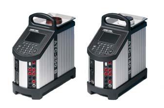
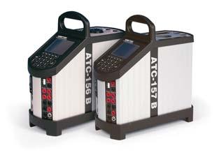
21 1.0 Introduction This user manual applies to the following instruments: JOFRA ATC-125 A Cooling calibrator JOFRA ATC-125 B Cooling calibrator with input panel JOFRA ATC-140 A Cooling calibrator JOFRA ATC-140 B Cooling calibrator with input panel JOFRA ATC-156 A Cooling calibrator JOFRA ATC-156 B Cooling calibrator with input panel JOFRA ATC-157 A Cooling calibrator JOFRA ATC-157 B Cooling calibrator with input panel JOFRA ATC-250 A Heating calibrator JOFRA ATC-250 B Heating calibrator with input panel JOFRA ATC-320 A Heating calibrator JOFRA ATC-320 B Heating calibrator with input panel JOFRA ATC-650 A Heating calibrator JOFRA ATC-650 B Heating calibrator with input panel These instruments are temperature calibrators designed to calibrate temperature sensors and thermostats. The ATC-125/156/157/320/650 A/B instruments are all designed as dry-block calibrators, where as the ATC-140/250 A/B instruments are designed to be used both as dry-block calibrators and liquid baths. Read this manual carefully before using the instrument and ensure that all safety instructions and warnings are observed
22 1.1 List of equipment received When you receive the instrument, the following should be enclosed: 1 calibrator 1 mains cable 2 sets of test cables (2 black, 2 red only B-versions) 1 CD-ROM containing software package JOFRACAL 1 AMETRIM-ATC/DTI software package to adjust the ATC series 1 RS232 serial cable 1 tool for insertion tube 1 traceable certificate (A versions) 2 traceable certificates (B versions) 1 reference manual 1 user manual ATC-125/156/157/320/650 A/B only 1 insertion tube user specified (incl. reference bore) 3 pcs. insulation plugs for 6, 10, 16 mm sensors (ATC-125/156 A/B only) or 3 pcs. insulation plugs for 5, 8, 11 mm sensors (ATC-157 A/B only) ATC-140/250 A/B only (dry-block) 1 dry block kit metric consisting of : - 1 insertion tube, multi-hole, metric, with 11 bores (incl. reference bore) - 1 pcs. insulation plug for multi-hole, metric (ATC-140 A/B only) or 1 dry block kit inch consisting of : - 1 insertion tube, multi-hole, inch, with 11 bores (incl. reference bore) - 1 pcs. insulation plug for multi-hole, inch (ATC-140 A/B only)
23 ATC-140/250 A/B only (liquid bath) 1 liquid bath kit consisting of : - 1 sensor basket - 2 lids for transportation / calibration - 1 stirring magnet - 1 stirring magnet remover - 1 liquid drainage syringe - 1 silicone oil

24 2.0 Safety instructions Read this manual carefully before using the instrument! In order to avoid any personal injuries and/or damage to the instrument all safety instructions and warnings must be observed. Disposal WEEE Directive These calibrators contain Electrical and Electronic circuits and must be recycled or disposed of properly (in accordance with the WEEE Directive 2002/96/EC). Warning About the use: The calibrator must not be used for any purposes other than those described in this manual. The calibrator has been designed for interior use only and should not be used in hazardous areas, where vapour or gas leaks, etc. may constitute a danger of explosion. The calibrator must be kept free within an area of 20 cm on all sides and 1 metre above the calibrator. NEVER use heat transfer fluids such as silicone, oil, paste, etc. in the dry-block calibrators. These fluids may penetrate the calibrator and cause damage or create poisonous fumes. When cleaning the well, REMEMBER to wear goggles when using compressed air in the dry-block calibrator and cleaning oil in the liquid bath calibrator
25 The ATC-125 contains the gases R-1270 and R-704 under pressure. The calibrator must under no conditions be stored or operated at ambient temperatures above 60 C (140 F) About the front panel: For B versions only, the sockets on the input module must NEVER be connected to voltages exceeding 5V for the TC/RTD sockets and 45V for the ma/v sockets proportional to ground. Thermostats must not be connected to any other voltage sources during test. About the insertion tubes and sensor: NEVER leave hot insertion tubes which have been removed from the calibrator unsupervised they may constitute a fire hazard. If you intend to store the calibrator in the optional aluminium carrying case after use, you must ensure that the instrument has cooled down to a temperature below 100 C/212 F before placing it in the carrying case. About the fuses: The fuse box must not be removed from the power control switch until the mains cable has been disconnected. The two main fuses must be identical and correspond to the chosen voltage. About the liquid bath: Ensure that the sensor is absolutely clean and dry as a few drops of water in the well (liquid bath) might cause a steam explosion. AMETEK Denmark A/S does not take any responsibility, if the well is filled with other fluids than the recommended
26 Heat transfer fluids must only be used in calibrators prepared as a liquid bath. If these fluids are overheated they will create noxious or toxic fumes. Proper ventilation must be used. Product information on the fluid must be carefully investigated before use. Do not handle hot oil. If the oil is heated beyond the flash point, it may constitute a fire hazard. Always set the max. SET temperature to a temperature 20 C below the flash point. Do not pour cold oil into a hot well it might cause an explosion. Do not pour water or any other liquid into a bath filled with hot oil. E.g. only a few drops of water might cause a steam explosion, if poured into 250 C hot oil. Caution Hot surface This symbol is engraved in the grid plate. Do not touch the grid plate, the well or the insertion tube when the calibrator is heating up they may be very hot. Do not touch the lid or the spill tray when the calibrator is heating up they may be very hot (liquid baths only). Do not touch the tip of the sensor when it is removed from the insertion tube/well it may be very hot. Do not touch the handle of the calibrator during use it may be very hot
27 Caution Cold surface If the calibrator has reached a temperature below 0 C/32 F, ice crystals may form on the insertion tube and on the well. This, in turn, may cause verdigris to form on the material. To prevent this from happening, the insertion tube and the well must be dried. This is done by heating up the calibrator to min. 100 C/212 F and any water left will evaporate. Remove the insulation plug while heating up. It is very important that humidity in the well and insertion tube is removed to prevent corrosion and frost expansion damages. Do not touch the well or insertion tube when these are below 0 C/32 F they can create frost-bites. Caution About the use: Do not use the instrument if the internal fan is out of order. About the liquid bath: Be careful not to overfill the well with oil. The oil level rises several centimetres when the temperature is rising to maximum. Do not attempt to remove hot oil overflow with the liquid drainage tube, as it might melt. When heated to high temperatures the liquid bath calibrator should be placed under an exhaust hood to remove any vapors given off by the oil. About the insertion tube and sensor: The tip of the sensor should rest at the bottom of the sensor basket for optimum results (liquid baths only)
28 If the sensor-under-test is short, be careful not to submerge the handle or wire inlet in the oil, as this might damage the sensor (liquid baths only). The insertion tube must always be removed from the calibrator after use. The humidity in the air may cause corrosion oxidation on the insertion tube inside the instrument. There is a risk that the insertion tube may get stuck if this is allowed to happen. Note The product liability only applies if the instrument is subject to a manufacturing defect. This liability becomes void if the user fails to follow the instructions set out in this manual or uses unauthorised spare parts
29 3.0 Operating the calibrator 3.1 Before use The ATC-B-version has a precision reference input. To achieve the high precision, a set of sensor coefficients relating to the specific sensor must be present in the ATC. Before use of the ATC, ensure that the correct coefficients in the ATC are equal to those from the sensors calibration certificate. This is done with the PC software JOFRACAL included on the CD. Please read how to do in the chapter Reference Sensors in the JOFRACAL user manual on the CD. Warning The calibrator must not be used for any purposes other than those described in this manual. The calibrator has been designed for interior use only and should not be used in hazardous areas, where vapour or gas leaks, etc. may constitute a danger of explosion. For B versions only, the sockets on the input module (fig. 3) must NEVER be connected to voltages exceeding 5V for the TC/RTD sockets and 45V for the ma/v sockets proportional to ground. Thermostats must not be connected to any other voltage sources during test. NEVER use heat transfer fluids, such as silicone, oil, paste, etc. to help inserting sensors in dry-block calibrators. These fluids may penetrate the calibrator and cause damage or create poisonous fumes. The calibrator must be kept free within an area of 20 cm on all sides and 1 metre above the calibrator. The ATC-125 contains the gases R-1270 and R-704 under pressure. The calibrator must under no conditions be stored or operated at ambient temperatures above 60 C (140 F)
30 3.1.1 Setting up the dry-block calibrator Follow the instructions below before using the calibrator (cf. fig. 1a) 1. Place the calibrator on an even horizontal surface where you intend to use it (pos. 1). Caution Do not use the instrument if the internal fan is out of order. Ensure a free supply of air to the internal fan located at the bottom of the instrument (pos. 2). 2. The area around the calibrator should be free of draught, dirt, flammable substances, etc. 3. Check that the voltage setting, shown on the power control switch (pos. 3), is identical to the mains voltage used. 4. Plug in the mains cable below the power control switch (pos. 4) and check that the earth connection is present. 5. Select an insertion tube (pos. 5) with a boring diameter matching the sensor (pos. 6) to be calibrated. Ensure that both the well and the insertion tube are clean. Insert the tube into the well. 6. Place the sensor (pos. 6) in the insertion tube (pos. 5) as shown in fig. 1a Setting up the liquid bath calibrator Follow the instructions below before using the calibrator (cf. fig. 1b). 1. Place the calibrator on an even horizontal surface in that place where you intend to use it. Place it in a way that will minimize the risk of tilting (pos. 1). It is recommended to cover the surface with a disposable cover in order to protect the surface against the silicone oil, if spilled. It is also recommendable to have a sufficient amount of disposable paper towels within reach
31 Caution Do not use the instrument if the internal fan is out of order. Ensure a free supply of air to the internal fan located at the bottom of the instrument (pos. 2). 2. The area around the calibrator should be free of draught, dirt, flammable substances, etc. 3. Place the parts from the liquid bath kit in the well in the following order : A. stirring magnet (pos. 3) B. sensor basket (pos.4) C. silicone oil (pos. 5) The recommended oil volume to a given test temperature is listed in the tables below. The recommended volumes must be adjusted to the actual job. ATC-250 A/B ATC-140 A/B For recommended 50 cst oil For recommended 10 cst oil 0 C - 50 C 100% -20 C - 50 C 100% 50 C C 95% 50 C C 95% 100 C C 90% 100 C C 90% 150 C C 85% 200 C C 80% Warning Do not pour cold oil into a hot well it might cause an explosion. AMETEK Denmark A/S does not take any responsibility, if the well is filled with other fluids than those recommended
32 Caution Be careful not to overfill the well with oil. The oil level rises several centimetres when the temperature is rising to maximum. Do not attempt to remove overflow of hot oil with the liquid drainage syringe, as it might melt. 4. The sensor basket (pos. 4) is marked with an optimum oil level mark (100%). When filling the well with oil and placing the sensors, this mark must never be exceeded. 5. Check that the voltage setting, shown on the power control switch (pos. 6), is identical to the mains voltage used. 6. Plug in the mains cable below the power control switch (pos. 7) and check that the earth connection is present. Switch on the calibrator. 7. Follow the procedure section 3.7 to access the Stirrer control menu. 8. Follow the procedure section 3.8 to select the SETtemperature according to the tables above. 9. Carefully monitor the oil level in the well, as the temperature rises, to prevent overflow. 10. Holes with a boring diameter matching the sensors to be calibrated must be drilled into the lid (pos. 8) before using it. 11. Place the calibration lid (pos. 8) onto the well, when the SETtemperature has been obtained. Warning Ensure that the sensor is absolutely clean and dry as a few drops of water might cause a steam explosion. 12. Place the sensor (pos. 9) vertically into the well using the optional support rod set for sensors for a correct position during calibration
33 Caution The tip of the sensor should rest at the bottom of the sensor basket for optimum results. If the sensor under test is short, be careful not to submerge the handle or wire inlet in the oil, as this might damage the sensor. 13. Start the calibration following the calibration procedure in this manual
34 3.2 During use Warning (liquid baths only) If the oil is heated beyond the fire point, it may constitute a fire hazard. Always set the max. SET temperature to a temperature 20 C below the flash point. Do not pour water or any other liquid into a bath filled with hot oil. E.g. only a few drops of water might cause a steam explosion, if poured into 250 C hot oil. Caution Hot surface This symbol is engraved in the grid plate. Do not touch the grid plate, the well or the insertion tube when the calibrator is heating up they may be very hot. Do not touch the lid or the spill tray when the calibrator is heating up they may be very hot (liquid baths only). Do not touch the tip of the sensor when it is removed from the insertion tube/well it may be very hot. Do not touch the handle of the calibrator during use it may be very hot. Caution (liquid baths only) It is vital that the stirring magnet is in place and spinning before any calibration attempts. The spinning magnet ensures optimum temperature homogeneity in the oil. It is strongly recommended to leave the lid on during calibration. Calibration without the lid may affect the temperature stability and homogeneity. When heated to high temperatures, the liquid bath calibrator should be placed under a exhaust hood to remove any vapors given off by the oil
35 3.3 Keyboard The keys on the keyboard activate the following functions (cf. fig. 2): Pos. Description SOFT KEYS used to select menu options displayed in the LCD. ENTER KEY used to accept selected options or entered values. NUMERIC KEYS used to type in values. INFORMATION KEY used to display the status of the parameters involved with the function currently selected. ESC KEY (escape key) used to cancel a selection/edit or return to previous menu. 3.4 Display The four separate areas within the display are used to indicate the following (cf. fig. 2): Pos. Description Informs you, by providing a heading, of the current function selected. Indicates, by use of an icon, the status of the calibrator. Provides the bulk of information and data available within the selection. Shows you the functions of the soft keys
36 3.5 Connections The instrument is designed for the following connections (cf. fig. 3): Pos. Description Power control switch with a cable connection and on/off switch. It also contains the main fuse. See section 4.0 for information on how to change the fuses and to adjust the voltage setting of the power control switch. Connection for synchronization output. Relay which is switching, when temperature stability is achieved. Connection for RS232 communication. Note that all PC-equipment, which are connected to the calibrator must observe the directive IEC950. Input for RTD sensor (2, 3 and 4 wire). Connection to chassis (earth/ground). Input for reference sensor. Voltage input. Passive ma input. Active ma input with 24V supply for transmitter. Connection for thermostat test. Note that this connection is for dead switches. TC connection for thermocouples. One of the inputs either,,, or can be selected displaying the SENSOR temperature in the setup and can be displayed as TRUE temperature. Note: Only the sensor type, which is to be tested, should be connected to the input panel
37 3.6 Calibrator functions overview The instrument's functions are divided into groups. See figs. 4 and Setting the speed level of the stirrer (liquid baths only) Follow the instructions to set the speed level of the stirrer (cf. fig. 14): Press to access the Set-Up menu. Press for more choices. Press to access the Stirrer menu. Press to edit the speed level of the stirrer. It is now possible to choose a speed setting between 0 and 50. Normal setting is between 10 and 15. Press to accept the value and return to the main menu screen. Caution If the speed level chosen is too high, the magnet will fall of and there will be no stirring in the oil. With no stirring of the oil, temperature gradients will emerge in the bath, which will again affect the result of the calibration
38 3.8 Selecting the SET temperature Follow the instructions to define the SET temperature (cf. fig. 4): Press. A cursor appears in the SET temperature field. Use the numeric keys to enter a new value, or to edit the existing value. Press to accept the value and return to the main menu screen. The calibrator now starts working towards the new SET temperature. 3.9 Calibration Note This Calibration function is for B versions only. This function enables you to perform automatic calibrations of multiple temperature sensors, using identical or similar settings that are defined in work orders created in the "JOFRACAL" PC program. For ease of use, the following instructions (cf. fig. 6) are split into two sections: Running a calibration Press to select the Calibration menu. Note: Calibration information is available in several places throughout the calibration menus using. Press to select the Run calibration menu. Use and to scroll through the list and highlight an existing work order
39 Press to continue the calibration using the highlighted work order or, Press to create a copy of the work order. Then press to accept the new name. Press to continue the calibration without editing the basic parameters or, Press to start the editor. Make the necessary changes, exit the editor and continue the calibration. If the sensor under test is a thermocouple sensor and the manual compensation mode is selected in work orders, a cold junction temperature must be defined. Press if you wish to overwrite the existing calibration and continue. If the work order is defined as a manual input, use: To enter values during the calibration. To enter values after the calibration. Follow the instructions on screen to connect the sensors and press to start the calibration. Note: a calibration can be stopped at any time, but this will erase all the calibration data. Follow the instructions on screen: To reposition the sensors (when an external manual heat source is used). To enter the step values (when manual input is required). When the calibration is complete, press or to store the results in the calibrator
40 3.9.2 Showing calibration results Press to select the Calibration menu. Press to select the Show calibration menu. Use and to scroll through the list and highlight a specific work order. Press to display the calibration details for the selected work order. The calibration results can be uploaded with the JOFRACAL PC program. This enables you to print out the results on a certificate SWITCH TEST Note This Switch test function is for B versions only. Switch test automatically locates the switch temperature of a thermostat. Three parameters are required: Start temperature (T 1 ) End temperature (T 2 ) Rate of change in temperature (slope rate). Hysteresis of a thermostat can also be obtained here. For ease of use, the following instructions (cf. fig. 8) are split into two sections:
41 Running a switch test Press to select the Switch test menu. Press to select Run switch test. Press a function soft key ( ) to enable the editor: (Note that T 1 can be greater than T 2 ) To edit the first set temperature (T 1 ). To edit the second set temperature (T 2 ). To determine hysteresis, toggle between "Yes" (a two temperature measurement) and "No" (a single temperature measurement). To edit the slope rate. The permitted range is C/min./ F/min. Note: the slope rate should be set so that the thermostat sensor can follow the temperature in the calibrator's well. Make the necessary changes and exit the editor by pressing. Press to start the switch test. While the switch test is in progress, you can press: To show the current switch test results. To review the switch test setup (no editing is possible). To stop the switch test at any time. When the switch test is complete, press or to store the results in the calibrator and return to the Switch test menu Showing switch test results Two types of switch test results are available: Results during a switch test. Results of a finished switch test
42 Results during a switch test Press to select Show result. This shows the results that are currently available. These results change as the test progresses. Press to return to the switch test. Results of a finished switch test Press to select the Switch test menu. Press to select Show result. Press a function soft key ( ) to select the results for one of the last five tests. The data in the information field is the same as that displayed at the end of the switch test AUTO STEP Auto step is used to step automatically between a range of different calibration temperatures. For ease of use, the following instructions (cf. fig. 9) are split into two sections: Running an auto step calibration Press to select the Auto step menu. Press to select Run auto step. Press to enable the editor to change the following values: No of steps: the number of temperature steps per direction (T 1 T x ). When a Two-way mode is selected,
43 the same number of steps are used for the second direction (T x T 1 ). Mode: toggle between "One-way" and "Two-way". Hold time: defines the time (in minutes) the temperature is maintained (after it is stable) for each step. T step values: must be set within the sensors permitted range. Make the necessary changes and exit the editor by pressing. Press to start the Auto step test. While the step test is in progress, you can press: To review the Auto step result (no editing is possible). To pause the test. and Force the test to jump a step (previous or next), regardless of the temperature step's stability. To stop the Auto step test. When the Auto step test is complete the results are displayed. Press or to finish the test and store the results in the calibrator Showing auto step test results Press to select the Auto step menu. Press to select Show results. Press a function soft key ( ) to select one of the last five Auto step tests stored in the calibrator. The data in the information field is the same as that displayed at the end of the Auto step test
44 3.12 SETUP The setup of this calibrator is divided into nine functions. Access to these functions is via three separate setup pages. The function keys and are used to navigate through these pages and functions (cf. figs. 10, 11, 12 and 13). For ease of use, the instructions are divided into 9 sections, each representing a function. Press to select the Setup menu Loading a setup (cf. fig. 10) Press (setup page 1) to select Load setup. Note that loading a setup results in all the parameters in the setup menu being overwritten. Use the keyboard to select a calibrator setup number (1 9). Press to load the selected setup. A warning informs you that the active setup will be overwritten. Press if you are sure you want to overwrite the existing setup and return to the Setup menu Saving a setup (cf. fig. 10) Press (setup page 1) to select Save setup to registry. Use the keyboard to select a register number (1 9). Press to save the current setup in the selected register and return to the Setup menu
45 Adjusting the display contrast (cf. fig. 10) Press (setup page 1) to select Display contrast. Press to make the display darker or display lighter. to make the Press to accept the new setting and return to the Setup menu Altering the temperature display settings (cf. fig. 11) Press (setup page 1) to select the Temperature menu. Use the function soft keys to set the parameters displayed. Setting the temperature units Press to select Unit. To select the temperature units, press: - To select Celsius. - To select Fahrenheit. - To select Kelvin. Press to accept the new setting. Setting the temperature resolution (cf. fig. 11) Press to select Temperature resolution. Press a function soft key to select the temperature type: - To select SET. - To select READ. - To select TRUE. - To select SENSOR. Press a function soft key to set the resolution
46 1 resolution. 0.1 resolution resolution. Press to accept the new setting and return to the Temperature resolution menu. Setting the max. SET temperature (cf. fig. 11) Press to select Max. SET temperature. Press. A cursor appears in the Max. SET temperature value. Use the numeric keys to enter a new value or press to edit the existing value. Press to accept the new setting and return to the Max. SET temperature menu. Converting electrical inputs to temperatures (cf. fig. 11) Press to select the Conversion to temp. menu. Setting voltage or current input conversions from the electric signal to a temperature reading. Press a function soft key ( ) to select the type of input. Press a function soft key to select a parameter and start the editor. Low input (voltage or current). Low input temperature that corresponds to the low level electrical signal. High input (voltage or current). High input temperature that corresponds to the high level electrical signal. Use the numeric keys to set a new value or press to edit the existing value
47 Make the necessary changes and press to accept the new setting(s), and to return to the Conversion to temperatures menu. Setting cold junction compensation temperatures Press to select Cold junction compensation. Press a function soft key to enable the editor: - To select compensation mode; toggle between Automatic and Manual. Note: when the automatic mode is selected, the calibrator measures the temperature in the T/C connector and uses this for the cold junction compensation of the thermocouple. - To define a Manual temperature for the cold junction compensation. This can be used when an external cold junction temperature can be established. Make the necessary changes and press to accept the new setting(s) and return to the Cold junction compensation menu Setting the sensor input parameters (B-versions only) (cf. fig. 12) Press (setup page 2) to select Input. Selecting the reference sensor input Press to select Reference sensor. Press a function soft key to enable the editor: - To select Internal reference source. Results in displaying the reference as READ. - To select External reference source (reference input on front panel). Results in displaying the reference as TRUE and the Internal reference is displayed as READ (a secondary value)
48 Check that the displayed serial number is the same, as on the reference sensor otherwise the sensors coefficients need to be downloaded to the ATC. This is done with the PC software JOFRACAL included on the CD. Please read how to do in the chapter Reference Sensors in the JOFRACAL user manual on the CD. - To change Convert to temperature function. Yes sets the readout of the External reference as a temperature. No sets the readout of the External reference in Ω values. - To change SET follows TRUE; toggle between On and Off. This function enables you to reach an exact TRUE temperature measured by the External reference sensor. Note that when ON is selected, the calibrator will let the temperature be set by the TRUE temperature. This means it will take longer before the calibrator indicates stable. Note: Set follows TRUE is only relevant when the External reference sensor is displayed in temperature units. Make the necessary changes and press to accept the new setting(s) and return to the Input menu. Note that when SET follows TRUE is on, it is indicated by a -symbol at the SET temperature. Selecting the input from the sensor under test Press to select Sensor under test. Press to select type of sensor
49 Press a function soft key to select a specific type of sensor: For voltage sensors (0 4V or 0 12V). For a 4 20mA sensor. For RTD sensors (Pt10, Pt50, Pt100, Pt500, Pt1000 Cu50 or Cu100). For thermocouple sensors (E, J, K, L, N, R, S, T, U or XK). For None (no sensor connected). Press a function soft key to select a specific sensor and return to the Sensor under test menu, which now displays the selected sensor and the convert to temperature status. Press to select Convert to temperature. This toggles between Yes (where inputs are converted to temperatures) and No (where no conversion is made). Press to accept the new settings and return to the Input menu Altering stability criteria (cf. fig. 12) Press (setup page 2) to select Stability criteria. The parameters displayed depend on the sensor selected. When none of the parameters displayed are active, then the calibrator s internal reference criteria provide the time to stable value. Stability values defined here are added to the internal reference stability criteria. Press to select the editor. Stability Time and Extended Stability Time can be set (in minutes) using integers from Stability intervals can be set in 0.01 steps from ±0.01 ±
50 Make the necessary changes and press to accept the new setting(s) and exit the editor Setting the access code The following features can be protected by an access code: Resetting the calibrator to Factory default settings. Setting the Maximum SET Temperature. Editing the Access code while it is enabled. (cf. fig. 12) Press (setup page 2) to select Access code. Press to start the editor. Use the numeric keys to type in a value from 0000 to (Typing 0000 disables the access code function.) Press to accept the new access code and exit the editor Resetting the calibrator setup to factory defaults Resetting to the factory default settings changes the setup to the initial settings (cf. fig. 13) Press (setup page 3) to restore Factory defaults. Caution By pressing (yes) the following will be deleted : Work orders Setup parameters Autostep results Switch test results
51 Press to restore Default factory settings About the calibrator (cf. fig. 13) Press (setup page 3) to select About. This informs you about the calibrator type, the software version installed and the date when it was last calibrated. Press or to return to the Setup menu
52 7 i 4 _ Setting the mains voltage and replacing the fuses Warning The fuse box must not be removed from the power control switch until the mains cable has been disconnected. The two main fuses must be identical and correspond to the chosen voltage. CAL IBRAT ION IN ST RUM ENTS F1 F2 F3 F4 F ESC Locate the main fuses in the fuse box in the power control switch and check the voltage of the power control switch (on/off switch (230V/115V)). If the voltage of the power control switch differs from the line voltage, you must adjust the voltage of the power control switch. Open the lid of the fuse box using a screwdriver. Remove the fuse box. Remove both fuses and insert two new fuses. These must be identical and should correspond to the line voltage. ATC-125/140/156/157: 115V, 5AT = 60B315 / 230V, 2.5AT = ATC-250/320/650: 115V, 10AF = 60B302 / 230V, 5AF = 60B
53 If the fuses blow immediately after you have replaced them, the calibrator should be returned to the manufacturer for service. Slide the fuse box into place with the correct voltage turning upwards
54 5.0 After use 5.1 Handling the dry-block calibrator Warning NEVER leave hot insertion tubes which have been removed from the calibrator unsupervised they may constitute a fire hazard. If you intend to store the calibrator in the optional aluminium carrying case after use, you must ensure that the instrument has cooled to a temperature below 100 C/212 F before placing it in the carrying case. Caution The insertion tube must always be removed from the calibrator after use. The humidity in the air may cause corrosion oxidation to form on the insertion tube inside the instrument. There is a risk that the insertion tube may become stuck if this is allowed to happen. Caution Cold surface If the calibrator has reached a temperature below 0 C/32 F, ice crystals may form on the insertion tube and on the well. This, in turn, may cause verdigris to form on the material. To prevent this from happening, the insertion tube and the well must be dried. This is done by heating up the calibrator to min. 100 C/212 F and any water left will evaporate. Remove the insulation plug while heating up. It is very important that humidity in the well and insertion tube is removed to prevent corrosion and frost expansion damages
55 Do not touch the well or insertion tube when these are below 0 C/32 F they can create frost-bites. The following routine must be observed before the insertion tube is removed and the instrument switched off : 1. If the calibrator has been heated to temperatures greater than 100 C/212 F, you must wait until the instrument reaches a temperature less than 100 C/212 F before you switch it off. 2. If the calibrator has reached a temperature less than 0 C/32 F, it should be heated to a temperature of 100 C/212 F (applies only to the ATC-125/140/156/157 AB models). Remove the insulation plug while heating up. 3. Switch off the calibrator using the power control switch (pos. 1 fig. 3). 4. Remove the insertion tube from the calibrator using the tool supplied. 5. Optional: Store the calibrator in its protective, aluminium carrying case. 5.2 Handling the liquid-bath calibrator It is not recommendable to leave the oil in the well for long-term storage. It is recommended to remove the oil from the well before transportation of the calibrator. Warning Do not handle hot oil. Do not attempt to remove overflow of hot oil with the liquid drainage tube, as it might melt. Do not leave any oil in the spill tray, as it might leak into the calibrator
56 Do not touch the items removed from the well - they may be very hot. NEVER leave hot items, which have been removed from the well, unsupervised they may constitute a fire hazard. The following routines must be observed before emptying the well : 1. Switch off the calibrator using the power control switch (pos. 7 fig. 1b). 2. Before handling the oil, it must be cooled down to a temperature close to ambient. 3. Remove the sensor basket and clean it with disposable paper towels. 4. Remove the stirring magnet using the stirring magnet remover supplied and clean it with disposable paper towels. 5. Empty the well using the liquid drainage tube supplied. Tilting the calibrator is not recommendable, as it increases the risk of splashing oil all over the test area. 6. Any remaining oil in the well is cleaned up using disposable paper towels. It is recommendable to use the optional cleaning oil when cleaning the well. Warning REMEMBER, wear goggles when using the cleaning oil. Do not inhale vapours. Proper ventilation must be used. Product information on cleaning oil must be carefully investigated before use
User manual Temperature Calibrator JOFRA CTC-140/320/650 A/B JOFRA CTC-1200 A Copyright 2005 AMETEK DENMARK A/S ( UK)
") User manual Temperature Calibrator JOFRA CTC-140/320/650 A/B JOFRA CTC-1200 A Copyright 2005 AMETEK DENMARK A/S (123199-UK) FIG. 1 1 2 3 4 5 CALI BRAT ION I NSTRUM ENTS 6 + - Switch Test RS232 7 8 11
User manual Temperature Calibrator JOFRA CTC-140/320/650 A/B JOFRA CTC-1200 A Copyright 2005 AMETEK DENMARK A/S (123199-UK) FIG. 1 1 2 3 4 5 CALI BRAT ION I NSTRUM ENTS 6 + - Switch Test RS232 7 8 11
User Manual Reference/Professional Temperature Calibrator Jofra RTC-125/157/158/159/250/700 A/B/C Jofra PTC-125/155/350/425/660 A/B/C
 User Manual Reference/Professional Temperature Calibrator Jofra RTC-125/157/158/159/250/700 A/B/C Jofra PTC-125/155/350/425/660 A/B/C User Manual Reference/ Professional Temperature Calibrator JOFRA RTC-156/157/158/159/250/700
User Manual Reference/Professional Temperature Calibrator JOFRA RTC-156/157/158/159/250/700 A/B/C JOFRA PTC-125/155/350/660 A/B/C
 User Manual Reference/Professional Temperature Calibrator JOFRA RTC-156/157/158/159/250/700 A/B/C JOFRA PTC-125/155/350/660 A/B/C User Manual Reference/ Professional Temperature Calibrator JOFRA RTC-156/157/158/159/250/700
User manual Temperature Calibrator JOFRA CTC-140/320/650 A/B JOFRA CTC-1200 A
 User manual Temperature Calibrator JOFRA CTC-140/320/650 A/B JOFRA CTC-1200 A User manual Temperature Calibrator JOFRA CTC-140/320/650 A/B JOFRA CTC-1200 A Copyright 2005 AMETEK DENMARK A/S (123199-UK)
Reference Manual Reference Temperature Calibrator JOFRA RTC-156/157/158/159/250/700 A/B/C
 Reference Manual Reference Temperature Calibrator JOFRA RTC-156/157/158/159/250/700 A/B/C Reference Manual Reference Temperature Calibrator JOFRA RTC-156/157/158/159/250/700 A/B/C Copyright 2012 AMETEK
Reference Manual Professional Temperature Calibrator Jofra PTC-125/155/350/425/660 A/B/C
 Reference Manual Professional Temperature Calibrator Jofra PTC-125/155/350/425/660 A/B/C Reference Manual Professional Temperature Calibrator JOFRA PTC-125/155/350/425/660 A/B/C Copyright 2012 AMETEK Denmark
Reference manual Reference Temperature Calibrator Jofra RTC-156/157/158/159/187/250/700 A/B/C
 Reference manual Reference Temperature Calibrator Jofra RTC-156/157/158/159/187/250/700 A/B/C Reference Manual Reference Temperature Calibrator JOFRA RTC-156/157/158/159/187/250/700 A/B/C Copyright 2012
User Manual Compact Temperature Calibrator Jofra CTC-155/350/660 A/C
 User Manual Compact Temperature Calibrator Jofra CTC-155/350/660 A/C User Manual Compact Temperature Calibrator JOFRA CTC-155/350/660 A/C Copyright 2016 AMETEK Denmark A/S List of contents 1.0 Introduction...
User- and Reference manual Temperature Calibrator JOFRA ETC-125 A / 400 A / 400 R
 User- and Reference manual Temperature Calibrator JOFRA ETC-125 A / 400 A / 400 R User- and Reference manual Temperature Calibrator JOFRA ETC-125 A / 400 A / 400 R Copyright 2005 AMETEK Denmark A/S (123943-UK)
Reference Manual Temperature Calibrator JOFRA ITC-155/320/650 A Copyright 2002 AMETEK DENMARK A/S
 Reference Manual Temperature Calibrator JOFRA ITC-155/320/650 A Copyright 2002 AMETEK DENMARK A/S About this manual. The structure of the manual This reference manual is aimed at users who are familiar
User- and Reference manual Temperature Calibrator JOFRA ETC-125 A / 400 A / 400 R Copyright 2005 AMETEK DENMARK A/S ( UK)
") User- and Reference manual Temperature Calibrator JOFRA ETC-125 A / 400 A / 400 R Copyright 2005 AMETEK DENMARK A/S (123943-UK) About this manual. The structure of the user- and reference manual The user
User- and Reference manual Temperature Calibrator JOFRA ETC-125 A / 400 A / 400 R Copyright 2005 AMETEK DENMARK A/S (123943-UK) About this manual. The structure of the user- and reference manual The user
Reference manual Compact Temperatur Calibrator Jofra CTC-140/320/650 A/B Jofra CTC-1200 A
 Reference manual Compact Temperatur Calibrator Jofra CTC-140/320/650 A/B Jofra CTC-1200 A Reference Manual Temperature Calibrator JOFRA CTC-140/320/650 A/B JOFRA CTC-1200 A Copyright 2003 AMETEK Denmark
Reference manual Industrial Temperatur Calibrator Jofra ITC-155/320/650 A
 Reference manual Industrial Temperatur Calibrator Jofra ITC-155/320/650 A Reference Manual Temperature Calibrator JOFRA ITC-155/320/650 A Copyright 2007 AMETEK Denmark A/S About this manual. The structure
Reference manual Temperature Calibrator JOFRA MTC-140/320/650 A
 Reference manual Temperature Calibrator JOFRA MTC-140/320/650 A Reference Manual Temperature Calibrator MTC-140/320/650 A Copyright 2001 AMETEK Denmark A/S About this manual. The structure of the manual
Service Manual Temperature Calibrators JOFRA CTC-140/320/650 A/B, CTC-1200 A JF INSTRUMENTS MTC-140/320/650 A Copyright 2003 AMETEK DENMARK A/S
 Service Manual Temperature Calibrators JOFRA CTC-140/320/650 A/B, CTC-1200 A JF INSTRUMENTS MTC-140/320/650 A Copyright 2003 AMETEK DENMARK A/S 2 26-03-2004 List of contents 1.0 General...4 1.1 Introduction...
ATC series JOFRA TM. Advanced Temperature Calibrator. Your choice for optimum temperature calibration. Specification Sheet NOTICE
 t e m p e r a t u r e Specification Sheet JOFRA TM Advanced Temperature Calibrator ATC series NOTICE New ATC models for both liquid and dry-block calibration Your choice for optimum temperature calibration
51 & 52 Series II. Users Manual. Thermometer. Test Equipment Depot Washington Street Melrose, MA TestEquipmentDepot.
 51 & 52 Series II Thermometer Test Equipment Depot - 800.517.8431-99 Washington Street Melrose, MA 02176 - TestEquipmentDepot.com Users Manual English September 1999 Rev.2, 11/10 1999-2010 Fluke Corporation,
Service Manual Temperature Calibrator JOFRA ATC-125/140/155/156/157/250/320/650 A/B Copyright 2007 AMETEK Denmark A/S
 Service Manual Temperature Calibrator JOFRA ATC-125/140/155/156/157/250/320/650 A/B Copyright 2007 AMETEK Denmark A/S 2 18-09-2007 122770 06 List of contents 1.0 General... 5 1.1 Introduction... 5 1.2
Model ATC-156/157/320 and 650 Advanced Temperature Calibrator
 t e m p e r a t u r e 99 Washington Street Melrose, MA 02176 Phone 781-665-1400 Toll Free 1-800-571-8431 Visit us at www.testequipmentdepot.com Specification Sheet SS-CP-2285-US Model ATC-156/157/320 and
 Distributed by: www.jameco.com 1-800-831-4242 The content and copyrights of the attached material are the property of its owner. 51 & 52 Series II Thermometer Users Manual English September 1999 Rev.1,
Model ATC-140/250 Advanced Temperature Calibrator
 t e m p e r a t u r e Model ATC-140/250 Advanced Temperature Calibrator Wide temperature range ATC-140-20 to 140 C (-4 to 284 F) ATC-250 28 to 250 C (82 to 482 F) Liquid bath or dry-block Use ATC-140 and
ITC series. Industrial Temperature Calibrators. Portable and easy-to-use temperature calibrator
 Specification Sheet temperature ITC series Industrial Temperature Calibrators Portable and easy-to-use temperature calibrator Wide temperature range ITC-155-23 to 155 C (-9 to 311 F) ITC-320 33 to 320
ST Wiring diagram. Product description. Temperature controller. Order number
 ST7-31.3 Temperature controller Order number 9154.12 Wiring diagram Product description The switching exits of the thermostatic controller can be programmed as -two-point controller with alarm -three-point
Series TCL-650S-D / TCL-165S-D TCL-M165S-B / TCL-M255S-B
 . Series TCL-650S-D / TCL-165S-D TCL-M165S-B / TCL-M255S-B Temperature Calibrator - 2 - Series TCL Series TCL Table of contents page 0 About this operating manual... 5 1 Device description... 6 1.1 Delivery,
Model ATC-125. Advanced Temperature Calibrator. Patented! t e m p e r a t u r e
 t e m p e r a t u r e 99 Washington Street Melrose, MA 02176 Phone 781-665-1400 Toll Free 1-800-517-8431 Visit us at www.testequipmentdepot.com Advanced Temperature Calibrator Model ATC-125 Patented! Wide
9142-B-P-156/AF. User s Guide. Field Metrology Well. Distribution is limited to DoD and U.S. DoD contractors only.
 9142-B-P-156/AF Field Metrology Well User s Guide Distribution is limited to DoD and U.S. DoD contractors only. May 2013 2013 Fluke Corporation. All rights reserved. Specifications are subject to change
User manual ma Loop Calibrator Jofra macal
 User manual ma Loop Calibrator Jofra macal User Manual macal ma loop Calibrator Copyright 2005 AMETEK DENMARK A/S LIST OF CONTENTS 1. INTRODUCTION 1.1 PACKING LIST... 2 2. SAFETY INSTRUCTIONS... 2 3.
ITC series. Industrial Temperature Calibrators. Portable and easy-to-use temperature calibrator
 t e m p e r a t u r e ITC series Industrial Temperature Calibrators Portable and easy-to-use temperature calibrator Wide temperature range ITC-155-23 to 155 C (-9 to 311 F) ITC-320 33 to 320 C (91 to 608
Model ATC-125 Advanced Temperature Calibrator
 t e m p e r a t u r e Model ATC-125 Advanced Temperature Calibrator Wide temperature range ATC-125 ultra cooler: -90 C to 125 C / -130 F to 257 F Portable calibration at low temperature State of the art
Lumitester PD-30. Instruction Manual. Table of Contents
 Table of Contents Lumitester PD-30 Instruction Manual Thank you very much for purchasing the Lumitester PD-30. All of this Instruction Manual must be read before operation of this product for safe and
DT304. Digital Temperature Logger INSTRUCTION MANUAL
 Test Equipment Depot - 800.517.8431-99 Washington Street Melrose, MA 02176 - TestEquipmentDepot.com DT304 INSTRUCTION MANUAL Digital Temperature Logger TABLE OF CONTENTS Introduction..........................................1
6109A / 7109A. Portable Calibration Baths. Four times more calibration throughput with twice the accuracy of Micro-Baths and dry-block calibrators
 6109A / 7109A Portable Calibration Baths Four times more calibration throughput with twice the accuracy of Micro-Baths and dry-block calibrators Portable calibration baths designed for clean process applications
CTC series. Compact Temperature Calibrators. Fast, timesaving, and reliable true temperature calibrator. Specification Sheet
 t e m p e r a t u r e Specification Sheet CTC series Compact Temperature Calibrators Fast, timesaving, and reliable true temperature calibrator Temperature ranges CTC-140 A -17 to 140 C / -1 to 284 F CTC-320
ST48-WHUV.102. Wiring diagram. Product description. PID controller. Order number
 ST48-WHUV.12 PID controller Order number 935.15 Wiring diagram Product description This micro-processed controller serves for temperature control at high measuring accuracy. Beside resistance sensors and
Model ITC-155/320 and 650 Industrial Temperature Calibrator
 t e m p e r a t u r e SS-CP-228-US NEW IMPROVED ACCURACY SPECIFICATIONS Model ITC-155/20 and 50 Industrial Temperature Calibrator Wide temperature range ITC-155-2 to 155 C / -9 to 11 F ITC-20 to 20 C /
USER S MANUAL G SERIES USER S MANUAL. Ref.49-MG000EN08
 USER S MANUAL G SERIES USER S MANUAL Ref.49-MG000EN08 Index USER S MANUAL 1. DESCRIPTION OF THE SERIE G SCALE... 1 1.1. KEYBOARD...1 2. INTRODUCTION... 2 2.1. GENERAL SPECIFICATIONS...2 2.2. OPERATIONAL
PHscan30S Pocket ph Meter Instruction Manual
 PHscan30S Pocket ph Meter Instruction Manual BANTE INSTRUMENTS CO., LTD PHscan30S Pocket ph Meter 1 Thank you for selecting the PHscan30S pocket ph meter. This manual provides a step-by-step guide to help
BT403. A Geno Technology, Inc. (USA) brand name. BT-300 Power Supply. Cat. No. BT
 brand name. BT-300 Power Supply. Cat. No. BT") BT403 A Geno Technology, Inc. (USA) brand name BT-300 Power Supply Cat. No. BT403 1-800-628-7730 1-314-991-6034 info@btlabsystems.com WARNING... 3 SAFETY INFORMATION... 3 ENVIRONMENTAL CONDITIONS... 4
BT403 A Geno Technology, Inc. (USA) brand name BT-300 Power Supply Cat. No. BT403 1-800-628-7730 1-314-991-6034 info@btlabsystems.com WARNING... 3 SAFETY INFORMATION... 3 ENVIRONMENTAL CONDITIONS... 4
CX-SERIES ADVANCED BATTERY CHARGER
 CX-SERIES ADVANCED BATTERY CHARGER Table of Content 1. IMPORTANT SAFETY INFORMATION... 2 1-1 General Safety Precautions... 2 1-2 Battery Precautions... 2 2. FEATURES... 3 2-1 Battery Charging Curve...
Eclipse Solar Suitcase
 Eclipse Solar Suitcase Renogy 100W 200W 2775 E. Philadelphia St., Ontario, CA 91761 1-800-330-8678 Version 1.0 Important Safety Instructions Please save these instructions. This manual contains important
User Manual Solar Charge Controller 3KW
 User Manual Solar Charge Controller 3KW Version: 1.3 CONTENTS 1 ABOUT THIS MANUAL... 1 1.1 Purpose... 1 1.2 Scope... 1 1.3 SAFETY INSTRUCTIONS... 1 2 INTRODUCTION... 2 2.1 Features... 2 2.2 Product Overview...
Induction Power Supplies
 Induction Power Supplies 7.5kW; 135 400kHz 480V version (Integral Heat Station) User s Guide Model 7.5-135/400-3-480 SMD Control Brds Rev. D 5/08 Table of Contents 1. Specifications and features...3 2.
CBC-9130 / V 30A / 24V 15A Pro. Charger. Operation manual
 CBC-9130 / 9215 12V 30A / 24V 15A Pro. Charger Operation manual Keep this manual in a safe place for quick reference at all times. This manual contains important safety and operation instructions for correct
EXPERT 2V4SA. Temperature Controller. User s manual CLEAN MODE COMPENSATION HUMIDITY OUTSIDE TEMPERATURE
 CLEAN MODE Temperature Controller User s manual CURRENT CONDITIONS ROOM TEMPERATURE PROBE TEMPERATURE OUTSIDE TEMPERATURE RELATIVE HUMIDITY STATIC PRESSURE TIME / DATE SETTINGS SET POINT / CURVE MINIMUM
 IU0U automatic charger Read these instructions carefully before the installation and commissioning and keep them in a safe place. Pass it on to the buyer in case of the further sale of the system. Contents
Installation Guide. ECL Comfort 210 / 310, application A231 / A Table of Contents
 1.0 Table of Contents 1.0 Table of Contents... 1 1.1 Important safety and product information..................... 2 2.0 Installation... 4 2.1 Before you start.....................................................
EC200 ELECTRONIC CONTROL SYSTEM
 1 INTRODUCING THE EC200 ELECTRONIC CONTROL SYSTEM With the use of new technology and an innovative approach to user interfacing, the EC200 Power Control System provides a complete control solution for
SB-300 Operator s Manual
 Test Equipment SB-300 Operator s Manual 20 Hand Held-Accuracy with a 40 Amp Load The SB-300 is a hand-held tester that is the auto industry s answer to portability in a professionally accurate battery
WP37 & HT37 User Manual
 WP37 & HT37 User Manual Origio WP37 & HT37 Warming Plates & Heated Trolley Warming Plates WP37 300 WP37 500 Heated Trolley HT37 Origio WP37 Component Description Heated work surface Model WP37 300 Power
Temperature Calibrator
 724 Temperature Calibrator Product Overview PN 1547851 February 2000 Rev.2, 8/05 2000-2005 Fluke Corporation. All rights reserved. Printed in U.S.A. All product names are trademarks of their respective
Lingenfelter NCC-002 Nitrous Control Center Quick Setup Guide
 Introduction: Lingenfelter NCC-002 Nitrous Control Center Quick Setup Guide The NCC-002 is capable of controlling two stages of progressive nitrous and fuel. If the NCC-002 is configured only for nitrous,
Fuel Level FL1. FL1 - User s manual. Rev Revision#2.0, 28/11/2014 For firmware version 1.2
 Fuel Level FL1 Revision#2.0, 28/11/2014 For firmware version 1.2 FL1 - User s manual Page intentionally left blank SECTIONS MECHANICAL INSTALLATION ELECTRICAL INSTALLATION OPERATING INSTRUCTIONS INSTRUMENT
OPERATING MANUAL Digital Diesel Control Remote control panel for WhisperPower generator sets
 Art. nr. 40200261 OPERATING MANUAL Digital Diesel Control Remote control panel for WhisperPower generator sets WHISPERPOWER BV Kelvinlaan 82 9207 JB Drachten Netherlands Tel.: +31-512-571550 Fax.: +31-512-571599
Inlet Controller TC5-ITA USER'S MANUAL. M rev. 02 K rev. 00
 Inlet Controller TC5-ITA USER'S MANUAL M 890-00047 rev. 02 K 895-00458 rev. 00 TABLE OF CONTENTS PRECAUTIONS... 3 FEATURES... 4 LOCATION OF THE CONTROLS... 5 Status Leds...5 Internal Switches...6 INSTALLATION
Standard Operating Procedure for the Struers Grinding and Polishing Tools
 Standard Operating Procedure for the Struers Grinding and Polishing Tools Page 1 of 19 Contents About the Struers Grinding and Polishing System... 2 RotoPol 31... 2 Rotoforce 4... 3 Multidoser... 4 Rotocom...
MTC Series. Marine Temperature Calibrator
 MTC Series Marine Temperature Calibrator Save Time, Save Money Up to 3 Year Calibration Interval Maximize accuracy with a one year recommended calibration interval, or lower your cost of ownership by extending
Model CTC-series Compact Temperature Calibrator
 t e m p e r a t u r e Model CTC-series Compact Temperature Calibrator Temperature ranges CTC-140 A -17 to 140 C / -1 to 284 F CTC-320 A 33 to 320 C / 91 to 608 F CTC-320 B 33 to 320 C / 91 to 608 F CTC-650
MODEL 520 REMOTE START ENGINE MANAGEMENT SYSTEM
 MODEL 520 REMOTE START ENGINE MANAGEMENT SYSTEM DSE 520 ISSUE 4 4/4/02 MR 1 TABLE OF CONTENTS Section Page INTRODUCTION... 4 CLARIFICATION OF NOTATION USED WITHIN THIS PUBLICATION.... 4 1. OPERATION...
ELIOS 25 DIGITAL CONTROL UNIT WITH LCD DISPLAY FOR THERMAL SOLAR SYSTEMS TDS 006 M00 0SE A
 ELIOS 25 DIGITAL CONTROL UNIT WITH LCD DISPLAY FOR THERMAL SOLAR SYSTEMS TDS 006 M00 0SE 012945A0 040906 1 MAIN FEATURES Power supply 230V~ ±10% 50Hz Backlit alphanumeric LCD display Management of 5 output
DIGITAL BATTERY TORQUE WRENCH (BC-RAD SELECT) USER GUIDE
 USER GUIDE") DIGITAL BATTERY TORQUE WRENCH (BC-RAD SELECT) USER GUIDE W.CHRISTIE (INDUSTRIAL) LTD CHRISTIE HOUSE, MEADOWBANK ROAD, ROTHERHAM, SOUTH YORKSHIRE, S61 2NF, UK T: +44(0)1709 550088 F: +44(0)1709 550030 E:
DIGITAL BATTERY TORQUE WRENCH (BC-RAD SELECT) USER GUIDE W.CHRISTIE (INDUSTRIAL) LTD CHRISTIE HOUSE, MEADOWBANK ROAD, ROTHERHAM, SOUTH YORKSHIRE, S61 2NF, UK T: +44(0)1709 550088 F: +44(0)1709 550030 E:
Temperature calibrators
 Operating manual (Translation) Operating manual... page 1-56 Temperature calibrators TP17 / TPM series SIKA Ba_TP17-TPM_en 02/2018. Please keep this operating manual for future reference. If the device
ECscan30 Pocket Conductivity/TDS Tester Instruction Manual
 ECscan30 Pocket Conductivity/TDS Tester Instruction Manual BANTE INSTRUMENTS CO., LTD ECscan30 Pocket Conductivity/TDS Tester 1 Thank you for selecting the ECscan30 pocket conductivity tester. This manual
Model CTC-series Compact Temperature Calibrator
 t e m p e r a t u r e 99 Washington Street Melrose, MA 02176 Phone 781-665-1400 Toll Free 1-800-571-8431 Visit us at www.testequipmentdepot.com Model CTC-series Compact Temperature Calibrator Temperature
The Traveler Series: Adventurer
 The Traveler Series: Adventurer RENOGY 30A Flush Mount Charge Controller Manual 2775 E. Philadelphia St., Ontario, CA 91761 1-800-330-8678 Version: 2.2 Important Safety Instructions Please save these instructions.
l The Battery Tester is designed for measuring the l AC four-terminal method to measure the internal
 Certificate of Calibration We hereby certify that this product has been calibrated and found to be in accordance with the applicable SPECIFICATIONS and STANDARDS. Accuracies of the standard equipment used
Bante220 Portable ph Meter Instruction Manual
 Bante220 Portable ph Meter Instruction Manual BANTE INSTRUMENTS CO., LTD Bante220 Portable ph Meter 1 Introduction Thank you for selecting the Bante220 portable ph meter. This manual provides a step-by-step
OPERATIONS MANUAL CR Thermoreactor
 OPERATIONS MANUAL CR 2200 Thermoreactor CR 2200 Note For the most recent version of the manual, please visit www.ysi.com. Contact Copyright YSI 1725 Brannum Lane Yellow Springs, OH 45387 USA Tel: +1 937-767-7241
Cannondale Diagnostic Tool Manual
 Cannondale Diagnostic Tool Manual For vehicles (ATV & Motorcycles) equipped with the MC1000 Engine Management System Software CD P/N 971-5001983 Data Cable P/N 971-5001984 POTENTIAL HAZARD Running the
Installation and Operating Instructions. Solar System Controller ISC3030
 Installation and Operating Instructions Solar System Controller ISC3030 ABOUT THIS MANUAL These operating instructions come with the product and should be kept with it as a reference to all user s of the
MoistureMatch A next generation grain tester
 MoistureMatch A next generation grain tester A next generation moisture tester incorporating new and unique technology. Finally, a portable tester that will more accurately match and track with the commercial
Rover Series. Rover 20A 40A Maximum Power Point Tracking Solar Charge Controller
 Rover Series Rover 20A 40A Maximum Power Point Tracking Solar Charge Controller 0 2775 E. Philadelphia St., Ontario, CA 91761 1-800-330-8678 Version 1.5 Important Safety Instructions Please save these
ECONOMISER SERIES E2T USER MANUAL
 TURBO S.R.L. Electronic Control Systems for Dust Collectors e-mail: info@turbocontrols.it web: www.turbocontrols.it TEL. ++39 (0)362 574024 FAX ++39 (0)362 574092 ECONOMISER SERIES E2T USER MANUAL 24/06/2014
Multi-gauge configuration For software V101
 Multi-gauge configuration For software V101 General Information The Multi-Gauge comes pre-configured and ready to go. Usually one need not make any extra settings. The only change one will wish to make
TMD90A Dual Input Digital Thermometer
 TMD90A Dual Input Digital Thermometer User Manual For detailed specifications and ordering info go to www.testequipmentdepot.com TMD90A Dual Input Thermometer Contents Safety Information 2 Symbols Used
Installation and Operating Instructions. MPPT Solar System Controller ISC3040
 Installation and Operating Instructions MPPT Solar System Controller ISC3040 ABOUT THIS MANUAL These operating instructions come with the product and should be kept with it as a reference to all user s
ECscan20 Pocket Conductivity Tester Instruction Manual
 ECscan20 Pocket Conductivity Tester Instruction Manual BANTE INSTRUMENTS CO., LTD ECscan20 Pocket Conductivity Tester 1 Thank you for selecting the ECscan20 pocket conductivity tester. This manual provides
PowerView PV380-R2 Mechanical Configuration
 PowerView PV380-R2 Mechanical Configuration Operations Manual *Products covered in this document comply with European Council electromagnetic compatibility directive 2004/108/EC and electrical safety directive
JConn Inv. PID Controller Instruction Manual
 JConn Inv. PID Controller Instruction Manual This information is specific to the Mypin TA4 based controller sold by JConn Inv. but it should work for most TA4 types - within limits. Table of Contents 1.
Envirotainer RAP e2 Container Operations Manual
 Operations Manual This manual is valid for: RAP container, P/N 140010R-() Version 1.5: 2016-04-15 www.envirotainer.com Operations Manual RECORD OF REVISION RECORD OF REVISION VER. NO. ISSUE DATE REVISION
Owner smanual Banks OttoMind Programmer
 with Installation Instructions Owner smanual Banks OttoMind Programmer w/economind Features 01-07 GM 8.1L Workhorse Class-A Motor Home 99-07 4.8L, 5.3L, 6.0L, 8.1L Trucks THIS MANUAL IS FOR USE WITH P/N
Operating Instructions. bluesmart Active
 Table of contents 1. Overview 3 2. Safety 3 2.1 Symbols in these instructions 3 2.2 Intended use 4 2.3 Responsibility of the operator 4 3. Setup and function 4 3.1 Brief description 4 3.2 Overview 5 3.3
USER GUIDE Digital Thermostat GUIDE D UTILISATION Thermostat digital Bedienungsanleitung Termostato digital 50-72
 BT D-01 1 2 USER GUIDE GB Digital Thermostat 4-25 GUIDE D UTILISATION F Thermostat digital 26-49 Bedienungsanleitung D Termostato digital 50-72 GUÍA DE USUARIO ES Termostato digital 74-97 GUIA DO UTILIZADOR
B-RAD Select USER MANUAL TABLE OF CONTENTS
 TABLE OF CONTENTS TABLE OF CONTENTS... 1 MANUAL REVISION HISTORY... 2 IMPORTANT SAFETY NOTICE... 3 1.0 General Information... 5 1.1 System Components... 5 1.2 Specifications... 5 1.2.1 Torque Ranges...
Digital Formaldehyde Meter
 USER GUIDE Digital Formaldehyde Meter Model FM100 Introduction EXTECH INSTRUMENTS Thank you for selecting the Extech Instruments Model FM100. The FM100 measures Formaldehyde CH 2 O (HCHO) concentration,
The Traveler Series TM : Adventurer
 The Traveler Series TM : Adventurer 30A PWM Flush Mount Charge Controller w/ LCD Display 2775 E. Philadelphia St., Ontario, CA 91761 1-800-330-8678 Version: 3.4 Important Safety Instructions Please save
Installation and Operating Instructions. Solar System Controller ISC3020
 Installation and Operating Instructions Solar System Controller ISC3020 ABOUT THIS MANUAL These operating instructions come with the product and should be kept with it as a reference to all user s of
FireLite Operation Manual
 FireLite Operation Manual Whip Mix Corporation 361 Farmington Ave. P.O. Box 17183 Louisville, KY 40217-0183 USA 502-637-1451 800-626-5651 Fax 502-634-4512 www.whipmix.com Table of Contents Specifications...2
User manual. Standard Modular Chiller HP 1/8 compressors with CAREL driver Application program for pco 1, pco 2, pco 3, pco C and pco XS.
 Standard Modular Chiller HP 1/8 compressors with CAREL driver Application program for pco 1, pco 2, pco 3, pco C and pco XS. User manual Manual version: 2.4 dated 27/02/08 Program code: FLSTDmMCDE LEGGI
MAKING MODERN LIVING POSSIBLE. UniLynx Indoor Installation Manual. ULX 1800i ULX 3000i ULX 3600i ULX 5400i SOLAR INVERTERS
 MAKING MODERN LIVING POSSIBLE UniLynx Indoor Installation Manual ULX 1800i ULX 3000i ULX 3600i ULX 5400i SOLAR INVERTERS Contents Contents 1. Introduction 2 Introduction 2 Installation Sequence 2 Important
Issue 2.0 December EPAS Midi User Manual EPAS35
 Issue 2.0 December 2017 EPAS Midi EPAS35 CONTENTS 1 Introduction 4 1.1 What is EPAS Desktop Pro? 4 1.2 About This Manual 4 1.3 Typographical Conventions 5 1.4 Getting Technical Support 5 2 Getting Started
Integrated temperature test and calibration bench Model CBS-SC4000
 Calibration technology Integrated temperature test and calibration bench Model CBS-SC4000 WIKA data sheet CT 92.33 Applications Testing and calibration of temperature measuring instruments such as: - Mercury
PURE SINE WAVE DC TO AC POWER INVERTER
 PURE SINE WAVE DC TO AC POWER INVERTER 60S-12A / 60S-24A 60S-12E / 60S-24E 100S-12A / 100S-24A 100S-12E / 100S-24E 150S-12A / 150S-24A 150S-12E / 150S-24E Instruction manual SINE WAVE INVERTER Please read
Begin to Use The New ESC: Before use the new ESC please carefully check every connections are correct or not. Yellow motor wire B Blue motor wire A
 HIMOTO ZTW Brushless Electronic Speed Control for car or truck Thank you for purchasing ZTW Brushless Electronic Speed Controller(ESC). The ZTW electronic speed control (ESC) is specifically designed for
FL-100-R (109) Operations and Installation Manual
 Operations and Installation Manual") Page 1 of 23 All specification subject to change 2002-2005 FL-100-R (109) Operations and Installation Manual This manual is certified for use with instrument serial number ASL000000 Use of this manual
Page 1 of 23 All specification subject to change 2002-2005 FL-100-R (109) Operations and Installation Manual This manual is certified for use with instrument serial number ASL000000 Use of this manual
Manual Calibrator PCE-IC1
 www.pce-industrial-needs.com Tursdale Technical Services Ltd Unit N12B Tursdale Business Park Co. Durham DH6 5PG United Kingdom Phone: +44 ( 0 ) 191 377 3398 Fax: +44 ( 0 ) 191 377 3357 info@tursdaletechnicalservices.co.uk
WE INCREASE UPTIME AND EFFICIENCY IN THE REFRIGERATION INDUSTRY
 Instruction Manual HBDF MK2 Defrost Sensor For automatic defrosting of evaporators Simple Setup, only two parameters and execution of a zero/start point during start-up. instruction manual - HBDF mk2 defrost
βeta 20A AUTO 12V/24V SOLAR CHARGE CONTROLLER WITH REMOTE METER
 βeta 20A AUTO 12V/24V SOLAR CHARGE CONTROLLER WITH REMOTE METER USER MANUAL βeta 20A AUTO 12V/24V SOLAR CHARGE CONTROLLER WITH REMOTE METER (OPTIONAL) CHARACTERISTICS LCD display: all systems parameters
MAGPOWR Spyder-Plus-S1 Tension Control
 MAGPOWR TENSION CONTROL MAGPOWR Spyder-Plus-S1 Tension Control Instruction Manual Figure 1 EN MI 850A351 1 A COPYRIGHT All of the information herein is the exclusive proprietary property of Maxcess International,
BRAKE TESTER DECELEROMETER
 OC3010_GBM_21009 BRAKE TESTER DECELEROMETER OWNER S MANUAL Version 8.++ ORBIT CONTROLS AG Zürcherstrasse 137 CH-8952 Schlieren/ZH Tel: + 41 44 730 2753 Fax: + 41 44 730 2783 info@orbitcontrols.ch www.orbitcontrols.ch
SmartPak Welding Controller WK-MPS-16 Constant Current
 SmartPak Welding Controller WK-MPS-16 Constant Current Features Latest state of the art ATMEL 8 bit microprocessor technology Synchronous digital welding control allows absolute precision Up to16 programmers