EM303A Caravan Manoeuvring System
|
|
|
- Sophia Powers
- 5 years ago
- Views:
Transcription


1 EM303A Caravan Manoeuvring System
2 TABLE OF CONTENTS Package contents (Parts list) Introduction Intended use Specifications Installation - safety guidelines Installation - mechanical components Installation - electrical/electronic components Installation - twin axle Operation - safety guidelines Operation - motor units Operation - remote control handset Operation - electronic control unit Operation - getting started Operation - hitching and unhitching Maintenance Trouble-shooting PACKAGE CONTENTS Ref Qte Description 1 1 Motor unit (A) 2 1 Motor unit (B) 3 1 Main cross bar 4 1 Electronic control unit 5 1 Remote control handset with lanyard 6 1 Emergency key 7 2 Aluminium chassis clamp plates (set) 8 4 Bolt - M10x Chassis U plate 10 1 Instruction manual 11 1 Convoluted cable trunking 14 1 Positive (+) red battery cable 1.8m including fuse holder & 80A fuse 15 1 Negative (-) black battery cable 1.6m 16 8 Bolt - M10x Nylon nut M Washer 10mmØ Screw - M4x Cable trunking P-clip 19.2mm Cable P-clip 10.4mm 22 4 Battery terminal connector 8mmØ 23 2 Battery terminal connector 6mmØ 24 4 Spade fork connector big 25 3 Cable number markers (1,2,3,4) 26 3 Cable polarity markers (+,-) Cable tie 2x Battery isolation switch, cover & key 30 2 Roller distance spacers 20x Rubber isolation shell for battery isolation switch 33 2 Screw M5x Spade fork connector small
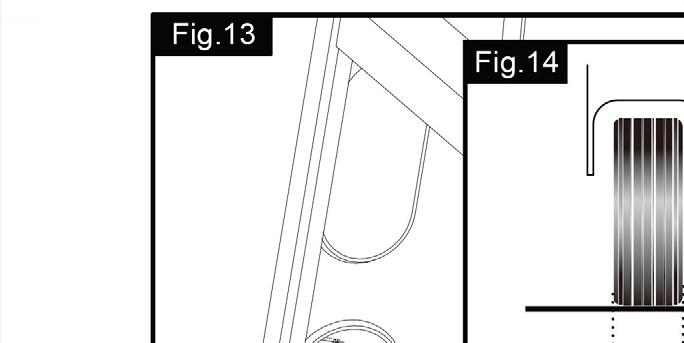
3 INTRODUCTION Congratulations on choosing the emove EM303A caravan manoeuvring system. This has been produced according to very high standards and has undergone careful quality control procedures. Simply by using the remote control handset you can move your caravan effortlessly into any position required within operating guidelines. Soft start and soft stop technology allows you to manoeuvre your caravan even more accurately without any shocks. The caravan manoeuvring system consists of two 12V motor-power rollers, a 12V electronic control unit and a remote control handset. To function, the motor-powered rollers must be engaged against the tyres of your caravan. The emove EM303A caravan manoeuvring system is provided with an automatic engaging system. By pushing two buttons on the remote control, both motor-powered rollers will be simply pressed on the tyre. Once this is done the manoeuvring system is ready for operation. The remote control will allow you to move your caravan in any direction. You can even rotate the caravan on its own axis without moving forwards or backwards (this function just can work under the single-axle function ). Before proceeding with installation and starting to use the manoeuvring system, please read this manual very carefully and be aware of all the safety instructions! The owner of the caravan will always be responsible for correct use. Keep this manual inside your caravan for future reference. INTENDED USE The emove EM303A caravan manoeuvring system is suitable for single axle and double axle caravans. Suitable only for L-profiled and U-profiled chassis with a chassis thickness between min. 2.8mm and max. 3.5mm. Depending on the weight of the caravan, the manoeuvring system cannot overcome obstructions that are more than about 2cm in height without assistance (please use wedges as a ramp). The standard installation kit only provides parts for installing the caravan manoeuvring system within the measurements given in Fig. 14. SPECIFICATIONS Designation Operational voltage Average current consumption Maximum current consumption Transmitting frequency remote control Speed Weight (2 motor set) Permissible overall Weight single axle (2 motors) Permissible overall Weight double axle (2 motors) Permissible overall Weight double axle (4 motors) Minimum width (caravan/trailer) Maximum width (caravan/trailer) Maximum tyre width Power source (battery) emove EM303A 12 Volt DC 20 Ampere 100 Ampere 868MHz approx. 9cm per sec. approx. 34kg (exclusive battery) 2250kg hard flat surfaces, 1800kg other surfaces, 1500kg on 18% gradient. 2250kg hard flat surfaces, 1800kg other surfaces, 1500kg on 18% gradient. 3500kg hard flat surfaces, 2500kg other surfaces, 1800kg on 18% gradient. 1800mm 2500mm 205mm LiFePO4: 12V, 20Ah Lead acid: 12V, 80Ah (min.) INSTALLATION - SAFETY GUIDELINES Read this user manual carefully before installation and use. Failure to comply with these rules could result in serious injury or damage to property. These symbols identify important safety precautions. They mean CAUTION! WARNING! SAFETY FIRST! IMPORTANT INFORMATION! Before starting installation under the caravan: Check the towing load of your vehicle and the gross weight of your caravan in order to establish whether they are designed for the additional weight. The manoeuvring system itself has a weight of about 34kg and a traditional lead acid battery has a weight of about 20-25kg.
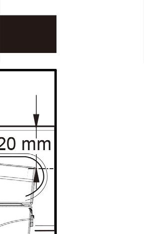
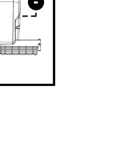
4 Check the minimal installation dimensions of the manoeuvring system based on figure 14. Only use adapters and accessories that are supplied or recommended by the manufacturer. Check that the caravan is disconnected from the battery supply and the mains electrical supply. Check that the tyres are not over worn and do have the same size and design (fitting to new or nearly new tyres is the best option). Make sure that the tyre-pressures are correct to the recommendation. Make sure the chassis is in good condition without any damage and is free from rust, dirt etc. Stop work immediately if you are in doubt about the assembly or any procedures and consult one of our engineers (Please refer to contact information on the last page of this manual). Locate the battery isolation switch to be accessible at all times when parking and moving the caravan. Do not remove, change or alter any parts of the chassis, axle, suspension or brake mechanism. Any drilling of holes in the chassis is not allowed. Do not install the unit if you are under the influence of drugs, alcohol or medication that could impair your ability to use the equipment safely. INSTALLATION - MECHANICAL COMPONENTS FOR PROFESSIONAL INSTALLATION ONLY! These instructions are for general guidance. Installation procedures may vary depending on caravan type. Working under a vehicle without appropriate support is extremely dangerous! Please refer to figure 13 for an overview of the whole assembly fully fitted. Place the caravan on a hard, level surface. The use of a lifting ramp or an assembly pit is ideal for access and personal safety. Unpack all the components and check for the presence of all parts (see package contents list). Write down, on the product warranty registration card, the 10-digit serial number (this is located on an aluminium plate on the side of one of the motor units). Clean the area of your chassis where you need to mount all components to ensure a good fitting. Make sure the caravan is prepared for installation. Check before installation that important areas, such as drains/spare tyre etc. do not cause any obstruction to the function of the caravan manoeuvring system. Ensure both rollers are in the DISENGAGED position (Fig. 10), as the unit will not fit correctly otherwise (Note: when fully disengaged, the pointer is positioned in the beginning of the yellow area). Loosely assemble the left hand motor unit (1), right hand motor unit (2) and main cross bar (3) (Fig. 1). The nuts (Fig. 1A), on the cross bar (3) to secure both motor units, must be no more than finger-tight at this stage. Note: In principle, the unit should be fitted in front of the caravan road wheels, but if fitting in this position is not possible because of obstacles or a too high hitch ball weight, it is permissible to fit it to the rear of the wheels by rotating the whole assembly (Fig. 1) by 180 degrees. Loosely fit the two clamping assemblies (7) to the chassis (Fig. 2 & 13) and attach. Use the bolts M10x60, nuts M10 and washers M10 (8,17,18) and put them in the diagonal positioned holes of the aluminium chassis clamp plates. Nuts must be no more than finger-tight. Assemble the pre-mounted manoeuvring system on the aluminium chassis clamp plates by using the two U- shaped brackets (9), bolts M10x50, nuts M10 and washers M10 (16,17,18). Nuts must be no more than fingertight. Make sure that aluminium drive rollers of the motors are approximately on the same altitude as the centre (axle) of the caravan wheel (0mm~40mm, see Fig. 10). As well make sure that between the top of the motor housing and the floor of the caravan is minimal 20mm space to make sure the motors can move freely (see Fig. 10 & 15). To compensate a possible unevenness (and lower the motors), emove has a set of distance plates available. One set can compensate 15mm. In total three sets can be used so that an altitude of 45mm can be compensated.
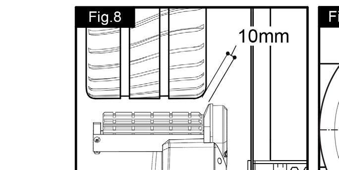
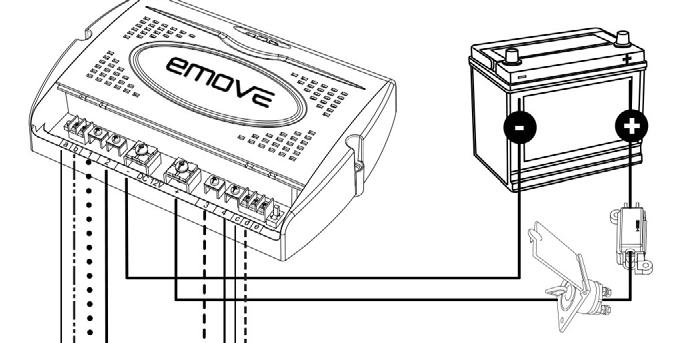
5 Adequate ground clearance: Please notice that the min. distance between the lowest line of motors and ground is 110mm, no matter what kind of chassis or install situation. Make sure that the main cross bar (3) is positioned in the middle of the caravan (the centre of the bar is marked). With the main assembly is loosely fitted onto the chassis, slide the whole assembly along the chassis until the rollers are 20mm away from the surface of the centre each tyre (Fig. 10). Two 20mm spacers (30) are provided. It is vitally important that each roller is at exactly the same distance away from the tyre. The whole assembly must be parallel to the caravan/trailer axle. Slide the motor units in or out of the cross bar (3) accordingly to ensure the roller will have the maximum possible contact with the tread of the tyre. Ensure that the position of each motor unit does not obstruct shock absorbers (if fitted) and that the gear cover (Fig. 8) is not too close to the surface of the tyre/shock absorber. The minimum clearance when the drive units swivelled in is 10mm. Re-check that there is sufficient space available (minimal 20mm) between the top of the motor housing and the floor of the caravan so the motors can move freely (Fig. 15). Fully tighten the four bolts (Fig. 1A) on the main cross bar (3) and lock them by the additional nuts. Fully tighten all the nylon nuts on both clamping assemblies (Fig. 2). First tighten the diagonal placed M10x60 bolts with a 20Nm torque, and then M10x50 bolts to a 40Nm torque. Re-check the distance of 20mm from the rollers to the tires, the position of the aluminium rollers in addition to the surface of the tire and finally the distance between the gear cover (Fig. 8) and the tires & shock absorbers (>10mm). The weight of the caravan must be on the wheels when doing this. If necessary, loosen the bolts and re-adjust the position of the assembly. Re-check that all bolts/nuts have been tightened to the correct torque! The main mechanical components have now been installed. INSTALLATION - ELECTRICAL/ELECTRONIC COMPONENTS Make sure the 12V supply from the battery and any 230V electricity supply are disconnected. Remove battery cable terminals and disconnect any external electrical power before starting work. Find a suitable place for the electronic control unit (4), such as a storage area, under a seat or a bed. Make sure this place is dry and close to the battery (40cm to 60cm). The electronic control unit can be mounted vertically on a side wall or be mounted flat. When mounted vertically, the connections must point downwards to avoid any short-circuits by objects falling into. Fix the electronic control unit securely into position with two screws M5x40 (33). Note: if the provided screws are not of suitable length or type for the desired location/material please substitute these as appropriate. Drill a 25mm hole through the floor of the caravan approximately 150mm centrally in front of the control unit (4) terminals. Caution! Take extra care to avoid any chassis members, gas pipes and electrical wires! Route and connect the motor-cables in accordance with wiring diagram (Fig. 12) (red = positive, black = negative). The wiring diagram (Fig Table. A (see below)) depicts the wiring route when installing the motor units in front of the wheels/axle towards the frame. Please refer to table B (below) for fitment of the motor units to the rear of the axle.
6 Table. A FRONT OF AXLE FITTING (4,6mm 2 cables) Motor unit A Positive (+) cable to terminal 4 Motor unit A Negative (-) cable to terminal 3 Motor unit B Positive (+) cable to terminal 2 Motor unit B Negative (-) cable to terminal 1 Automatic engaging system (1,5mm 2 cables): Motor unit A: Positive (+) cable to terminal d Motor unit A: Negative (-) cable to terminal c Motor unit B: Positive (+) cable to terminal b Motor unit B: Negative (-) cable to terminal a Table. B REAR OF AXLE FITTING (4,6mm 2 cables) Motor A Positive (+) cable to terminal 1 Motor A Negative (-) cable to terminal 2 Motor B Positive (+) cable to terminal 3 Motor B Negative (-) cable to terminal 4 Automatic engaging system (1,5mm 2 cables): Motor unit A: Positive (+) cable to terminal b Motor unit A: Negative (-) cable to terminal a Motor unit B: Positive (+) cable to terminal d Motor unit B: Negative (-) cable to terminal c Mark the motor cables (12 & 13) for both motor units using the cable markers (25). The cables for the left and the right motor should have the same length. Avoid any loops. Connect the spade connectors to the motors. Please note that the red cable is connected to the terminal under the moulded + symbol on the weatherproof terminal cover. Remember to leave a small amount of slack cable near the motors to allow for their movement when the drive rollers are engaged. Route all the cables along the underside of the caravan floor, inside the supplied convoluted trunking (11) (this will protect the electrical cables against sharp edges and dirt) and through the drilled hole. Secure the cable trunking (11) to the chassis or under body of the caravan by using the P-Clips (20) and screws (19). Once the all cables are through the drilled hole next to the control unit (4), cut the cables, ensuring that they are the same length. Remove approx. 5mm of the insulation from the ends. Fix the big spade fork connectors (24) to the motor cables and the small spade fork connectors (34) to the automatic-engaging-cables by using crimping pliers. A secure and good quality connection on each cable is essential. Attach the spade fork connectors to the terminals on the control unit (see wiring diagram Fig. 12) and fix them tightly by the screws. A safe and good quality connection on each cable is again essential. Find a suitable place for the battery power isolation switch (29) which includes an external holder with hinged cover. Important: The switch must be mounted onto the exterior body of the caravan and be easily accessible from the outside of the caravan in case of any emergency. The switch must be mounted close to the location of the battery in order to keep the length of the battery cables to a minimum. Use the cardboard template to position the hole positions and the drill holes. Mount the switch and the housing with the bolts, washers and nuts, and finally mount it on the caravan with stainless steel screws (19). Route the positive (+) power cable (including fuse) from the battery to the battery power isolation switch (29) and than further to the control unit (4). The electronic connections of the battery power isolation switch (29) must be covered by the supplied rubber isolation shells (31). Route the negative (-) power cable directly to the control unit (4). No cables may be routed over the control unit! Again it is recommended to use the supplied trunking (11) to protect the cables against sharp edges. Attach the trunking with P-clips (20) and P-clip screws (19). Cut the cables to an appropriate length and remove approx. 5mm of the insulation from the ends. Fix the battery terminal connectors by using crimping pliers. Two types of battery terminal connector (22 & 23) are provided for use as appropriate. A secure and good quality connection on each cable is essential. Connect the battery cables (14 & 15) to the control unit (4): Attach the spade fork connectors to the positive (+) en negative (-) terminal of the control box and fix them tightly by the screws. Connect the battery cables to the existing battery terminals (red = positive, black = negative).
7 Caution! Make sure that you do not reverse the Positive (+) and Negative (-) connections. Incorrect connection (reverse polarity) will result in damage to the control unit. Connect the battery cables (14 & 15) to the control unit (4). Seal the 25mm hole in vehicle under body using plastic body sealant. Installation of the caravan manoeuvring system is now complete. INSTALLATION TWIN AXLE This manual describes the general installation and use of the manoeuvring system for single axle caravans. When you use the manoeuvring system for a twin axle caravan, please check the following: Permissible overall weight twin axle (2 motors) Permissible overall weight twin axle (4 motors) 1800kg (1500kg on 18% gradient) 2500kg (1800kg on 18% gradient) 2 motors: The procedure for installing a 2 motors manoeuvring system on a twin axle caravan is the same as for a single axle caravan. The electronic control unit (4) only must be prepared for twin axle use: Turn off the battery power isolation switch and move the single/twin axle function switch (Fig 3S/T) on the control unit to the twin axle position (Fig. 3T), so that the manoeuvring system can be used for a twin axle caravan. In the twin axle function when making curves, all wheels will drive but at a different speed. 4 motors: The procedure for installing a 4 motors manoeuvring system on a twin axle caravan is similar than for a single axle caravan but then with two sets of manoeuvring system. Follow the procedure for installing the mechanical components twice: one time for the manoeuvring set mounted in front of the twin axle and one time for the manoeuvring set mounted behind the twin axle. Follow the procedure for installing the electrical/electronic components twice: one time for the manoeuvring set mounted in front of the twin axle and one time for the manoeuvring set mounted behind the twin axle. Note: When installing the four motors it will be necessary to use one higher capacity battery to supply both sets of manoeuvring system (including two electronic control units and two of battery power isolation switches). Do not use two separate batteries for a 4 motors manoeuvring system on a twin axle caravan. Now both electronic control units (4) must be prepared for twin axle use: Turn off the battery power isolation switch and move the single/twin axle function switch (Fig 3S/T) on the control unit to the twin axle position (Fig. 3T), so that the manoeuvring system can be used for a twin axle caravan. In the twin axle function when making curves, all wheels will drive but at a different speed. Finally both electronic control units (4) must be prepared for the use of only one remote handset (32). The remote handset need to be synchronised with both electronic control units using the following procedure: Check the installation in accordance with the installation instructions and ensure that the drive rollers are not applied. Check that the battery is properly connected, check the condition of the battery and that a voltage of 12V is present at the control unit. Please ensure that both battery isolation switches are on. Activate the remote control handset by sliding the slide switch to On -I (Fig. 5A). The green LED on the remote control handset (Fig. 5H) starts to flash slowly. Press the reset button (Fig. 3A) on the control unit. All three LED s on the control unit (Fig. 3B, 3C & 3D) will flash slowly. Press both forwards (Fig. 5B) and reverse (Fig. 5C) button on the remote control handset for about 3 seconds. Then the handset buzzer will give a short beep to confirm that the synchronisation is complete. After successful synchronisation, the green LED on the control unit (Fig. 3B) and on the remote control handset (Fig. 5H) will illuminate continuously. Repeat this procedure with the second electronic control unit. Turn the remote handset Off and then On again so both control units will be activated. The installation of the caravan manoeuvring system for twin axle use is now complete. For details of the operation, use and all the LED and button functions, please refer to the standard chapters of this manual.
8 OPERATION - SAFETY GUIDELINES Practice operating the manoeuvring system in an open area before using for the first time. This is to fully familiarise yourself with the handset / manoeuvring system operation. Before use, always check the caravan manoeuvring system for any damage. When towing or moving the caravan please be aware, at all times, that ground clearance is reduced when the manoeuvring system has been fitted. Always ensure that children and pets are kept well out of the way during operation. When operating the system, ensure that no hairs, fingers or other body parts, clothing or any other objects carried on the body can become trapped by moving or rotating parts (e.g. drive rollers). In the event of malfunctions, pull on the handbrake immediately and turn off the main isolation power switch. To maintain signal strength, always make sure that, during manoeuvring, the distance between the remote control and the caravan does not exceed 5 metres. Due to the nature of a radio signal, it can get corrupted by external terrain or objects. So there may be small areas around the caravan where the quality of reception reduces, hence the manoeuvring system may stop momentarily. Always be aware that the manoeuvring system increases the weight of your caravan or trailer. So this reduces the payload of the caravan. Do not exceed the total safe working load of 1800kg laden weight (caravan including load) when 2 motors are used and 2500kg laden weight (caravan including load) when 4 motors (twin axle) are used. Always make sure that the rollers are fully disengaged from the tyres when the manoeuvring system is not in use. This is better for the tyres and for the system. Always make sure that the rollers are fully disengaged before towing/moving the caravan by vehicle or manpower. This can damage the tyres, manoeuvring system and the towing vehicle. Always make sure that after you have finished using the manoeuvring system, the battery power isolation switch (29) is switched off and the key is removed and stored in a safe place (out of reach of children or other unauthorised people). If you switch off, the battery will be discharged by the small current. Always make sure that the remote control handset is switched off and stored (in the wall holder) in a safe place (out of reach of children or other unauthorised people). If you switch off, the battery will be discharged by the small current. Do not rely on the manoeuvring system to act as a brake. Always apply the handbrake after manoeuvring, before disengaging the drive rollers from the tyres. Do not use the manoeuvring system as a support when jacking up the caravan, since this can damage the drive unit. Depending on the weight of the caravan, the manoeuvring system cannot overcome all obstructions without assistance. Please use wedges as a ramp. All wheels and tyres on the caravan must be of the same size and design. If tyres are worn or new tyres are fitted, the distance between the drive rollers and the tyres may need readjusting (see - Mechanical Sensitive objects such as cameras, DVD-Players etc. Must not be kept in the stowage box near the control unit or the motor cable. They can be damaged by the electromagnetic fields. Do not make any modifications on the caravan manoeuvring system (mechanical or electronically). This can be very dangerous! No warranty claim will be accepted and we cannot guarantee the function of the system if any modifications are made. We will not be liable for any damage whatsoever caused as a result of incorrect installation, operation or modification.
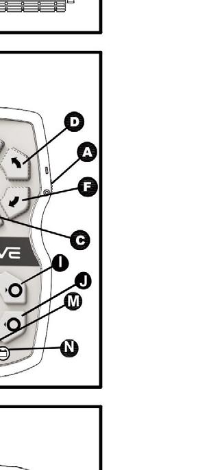
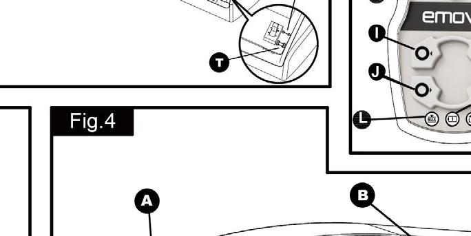
9 OPERATION - MOTOR UNITS The manoeuvring system has two motor units (1 & 2). In general they are mounted in front of the axle of the caravan. Both units are identical but cannot be switched. Fig. 4 A. Aluminium drive roller B. 12V Motor C. Motor connection terminals (+ and -) D. Motor for automatic engaging system E. Base unit F. Drive unit G. Gear Traction indicator label: The yellow-green-red traction indicator label (Fig. 11A), on the side of each motor unit indicates if the roller is depressing the tyre sufficiently to provide adequate traction. If the pointer is in the yellow area Rollers are not touching or depressing the tyre sufficiently. If the pointer is in the green area Rollers should be connecting correctly to the tyre (margin of 15mm). If the pointer is in the red area Rollers are connected to the tyre but in an extreme position. It could be that the tyre of the caravan has insufficient air pressure or the drive unit has been knocked out of position and a visit to a workshop is required to reposition the assembly. Disconnect the motor powered rollers in case of emergency: In the case that the caravan battery is discharged to far to automatically take of the motor powered rollers of the tyre, or there is a defect, you can also do this manually. See figures 9 & 9.1. Take the plastic cap (Fig. 9B) at the rear side of the housing of the motor for the automatic engaging system. If necessary use a screwdriver. Place the emergency key (6) on the emergency socket in the motor unit (Fig. 9A & 9.1C) and turn it until the motor unit including motor powered rollers are in the beginning position. Repeat this also on the motor unit on the other side. Put the plastic caps back on the motor housing. As soon as the battery is charged again, or the problem is solved, the motor powered rollers automatically work again. OPERATION - REMOTE CONTROL HANDSET The remote control handset (5) is powered by one PP3 9Volt battery, and is activated by moving the slide switch to -I (Fig. 5A). Once activated the green LED (Fig. 5H) will illuminate and the directional controls can now be used. Fig. 5 A. Slide switch O and -I) B. Caravan forwards (both wheels rotate in forwards direction) C. Caravan reverse (both wheels rotate in reverse direction) D. Caravan left forwards (right wheel rotates in forwards direction) E. Caravan right forwards (left wheel rotates in forwards direction) F. Caravan left reverse (right wheel rotates in reverse direction) G. Caravan right reverse (left wheel rotates in reverse direction) H. Green LED: reflects status of the remote control and caravan manoeuvring system I. Two handed service for automatic engaging of the motor powered rollers to the tyre J. Two handed service for automatic disengaging of the motor powered rollers from the tyre K. Blue LED: reflects status of the automatic engaging system L. Red overload LED: Amp overload protection is activated. Wait about 60 seconds and try again. M. Blue 9V battery LED: The internal 9V battery of handset is near empty and needs to be replaced. N. Blue battery voltage LED: Caravan battery voltage too low or too high. When you drive straight forwards or reverse (press button B or C), it is also possible to adjust the direction by additional pressing button D or E (when driving forwards) or button F or G (when driving reverse). In addition, the (E) and (F) buttons or (D) and (G) buttons may be pressed at the same time to turn the caravan around on its own axis without moving forward or backward (this function just can work under the -axle When you switch within 2 seconds from forward driving to reverse driving (and the other way around), a small delay of 1 second will appear to protect the electronics and the motors.
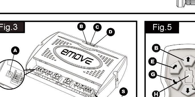
10 The slide switch (Fig. 5A) also acts as an The automatic engaging system: To activate the automatic engaging system of the motor powered rollers on the tyre, press the two buttons for engaging (Fig. 5I) or disengaging (Fig. 5J) for at least three seconds. The blue LED (Fig. 5K) will blink fast during these three seconds and every second there will be a beep. This warns you that the system will be activated! Engaging: After these three seconds the motor powered rollers will be pressed against the tyre, and the blue LED will illuminate constant. Now you can release the two buttons. When the motor powered rollers are pressed on the tyre strongly enough you hear a short beep, the blue LED will switch off and the system is ready to use. Disengaging: after these three seconds the motor powered rollers will be released from the tyre, and the blue LED will illuminate constant. Now you can release the two buttons. When the motor powered rollers are completely disengaged you hear a short beep, the blue LED will switch off and is the system ready for transport. The remote hand set switches off: After 3 minutes, if no button is pressed: After 2 minutes the buzzer will beep for 5 times with a repetition after 3 minutes. Than the system switches in the - modes. After 6 minutes, if one of the movement buttons is permanently held down: After 5 minutes the buzzer will beep for 5 times with a repetition after 6 minutes. Than the system switches in the - modes. The green LED goes off and the remote control handset is in the - modes which means that there always will be used some current which causes the battery to go down. So always make sure the remote control handset is turned off by the slide switch. To reactivate the remote control, move slide switch to O and then back to -I after approximately 1 second. Error messages via the remote control handset: Error messages of the emove EM303A will be communicated via the remote control handset by the green LED (Fig. 5H), the error message (Fig. 5L, 5M & 5N) and a buzzer signal: Green LED (Fig. 5H) off, no buzzer: remote control handset is turned off and also system is not activated Green LED (Fig. 5H) continue on, no buzzer: remote control handset is turned on and system is activated and ready to use. Green LED (Fig. 5H) is blinking, no buzzer: no communication between handset and control unit. This could be because of too much distance between remote control handset and control unit, or the battery isolation switch for manoeuvring system is not turned on or that there is a distortion signal disturbing the communication. As soon as connection is good again the green LED will be continue on and the system is ready to use. Blue battery voltage LED (Fig. 5N) is blinking in combination with buzzer (2 times blinking, break, 2 times blinking, break etc.): Battery voltage too low (<10V). Battery needs to be recharged. Blue battery voltage LED (Fig. 5N) is blinking in combination with buzzer (4 times blinking, break, 4 times blinking, break etc.): Battery Voltage too high (over charged). Try to discharge the battery by turning on a user (for example a lamp or water-pump). Red overload LED (Fig. 5L) is blinking in combination with buzzer (6 times blinking, break, 6 times blinking, break etc.): Amp overload protection is activated. Wait about 60 seconds and try again. Blue 9V battery LED (Fig. 5M) is blinking, no buzzer: The internal 9V battery is near empty and needs to be replaced. Changing batteries in the remote control: When the battery is empty (blue 9V battery LED (Fig. 5M) is blinking), it needs to be replaced. Open the rear cover of the handset (Fig. 7A). Take out the dead/old battery and dispose in the appropriate way. Install a new replacement battery (Fig. 7.1). Make sure to use a leak proof PP3 (9Volt) battery (No claims under guarantee can be considered for damage caused by leaking batteries). Close the rear cover again. Dead and used batteries may leak and damage the remote control handset! Remove the batteries if the handset is not going to be used for an extended period. OPERATION - ELECTRONIC CONTROL UNIT The electronic control unit (4), which is mounted inside your caravan, is responsible for controlling the manoeuvring system. The control unit has three one pushbutton and one slide switch (Fig. 3): Green LED (Fig. 3B): Power LED continuously illuminated when system is activated (by moving slide switch to -I). If the handset far away from the control unit, beyond the availably distance, this LED will go out. Blue LED (Fig. 3C): Error message LED concerning caravan battery:
11 Blue LED is blinking (2 times blinking, break, 2 times blinking, break etc.): Battery voltage too low (<10V). Battery needs to be recharged. Blue LED is blinking (4 times blinking, break, 4 times blinking, break etc.): Battery Voltage too high (over charged). Try to discharge the battery by turning on a user (for example a lamp or water-pump). Red LED (Fig. 3D) is blinking (6 times blinking, break, 6 times blinking, break etc.): Amp overload protection is activated. Wait about 60 seconds and try again. In general all error messages will reset automatically after one minute. If this is not the case, reset the electronics of the manoeuvring system by switching off the system via the isolation switch and the remote control handset for at least 15 seconds and then turning it on again. The Reset Button (Fig. 3A): The remote control handset and the control unit are synchronised with each other in the factory. If the control unit or the remote control handset is replaced, they must be re-synchronised as described below: Check the installation in accordance with the installation instructions and ensure that the drive rollers are not applied. Check that the battery is properly connected, check the condition of the battery and that a voltage of 12 V is present at the control unit. Please ensure that the battery isolation switch is on. Activate the remote control handset by sliding the slide switch to -I (Fig. 5A). The green LED on the remote control handset (Fig. 5H) starts to flash slowly. Press the reset button (Fig. 3A) on the control unit. All three on the control unit (Fig. 3B, 3C & 3D) will flash slowly. Press both forwards (Fig. 5B) and reverse (Fig. 5C) button on the remote control handset for about 3 seconds. Then the handset buzzer will give a short beep to confirm that the synchronisation is complete. After successful synchronisation, the green LED on the control unit (Fig. 3B) and on the remote control handset (Fig. 5H) will illuminate continuously. The single-twin axle function switch (Fig. 3S/T): The emove EM303A caravan manoeuvring system is suitable for both single axle and twin axle caravans. You just need to pull the single-twin axle function switch (Fig 3S/T) on the control unit, so that the manoeuvring system can be used for a single-axle caravan or a twinaxle caravan (for 2 motor use but also for 4 motor use). In the twin axle function the all wheels will drive but at a different speed. The switch standard pre-selected for single axle use (Fig 3S). For twin axle use, just move the switch to the twin axle position (Fig. 3T). When move the single-twin axle function switch, the battery power isolation switch (29) must be turned off. OPERATION - GETTING STARTED Please make sure you read the safety instructions very carefully and make sure that you follow these guidelines! Make sure that the battery that supplies the system is fully charged and in good condition. Make sure that the caravan is free from the vehicle and the handbrake is on. Also make sure that the corner steady feet are fully raised. Turn on the battery power isolation switch (29). Activate the manoeuvring system by move slide switch to -I on the remote control (Fig. 5A). The green LED (Fig. 5H) on the remote control handset will illuminate and you will hear a short beep. The remote control is ready for use. Press at the same time, during at least three seconds, the two buttons for engaging the motor powered rollers (Fig. 5I). The blue LED (Fig. 5H) will blink fast during these three seconds and every second there will be a beep. This warns you that the system will be activated! After these three seconds the motor powered rollers will be pressed against the tyre and the blue LED will illuminate constant. Now you can release the two buttons. When the motor powered rollers are pressed on the tyre strongly enough, the blue LED will switch off and is the system ready to manoeuvre. The colour of the traction indicator label (Fig. 11A) should be into the green area. Before operating the manoeuvring system, release the handbrake. Now you can choose the movements according the symbols shown on the remote control. Straight forward (Fig. 5B), straight reverse (Fig. 5C), left forward (Fig. 5D), left reverse (Fig. 5F), right forward (Fig. 5E), right reverse (Fig. 5G).
12 In addition, the left forward (Fig. 5D) and right reverse (Fig. 5G) buttons or right forward (Fig. 5E) and left reverse (Fig. 5F) buttons may be pressed at the same time to turn the caravan around on its own axis without moving forward or backward (this function just can work under the -axle When you drive straight forwards or reverse (press button 5B or 5C), it is also possible to adjust the direction by additional pressing button 5D or 5E (when driving forwards) or button 5F or 5G (when driving reverse). Because of the technology, the caravan will slowly speed up. Because of the technology, the caravan will stop slowly. This allows you to manoeuvre your caravan even more accurately without any shocks. WARNING: When the buttons on the remote control handset are released, the caravan will slowly stop after 0.5 second and continue to move about 6cm (depending on final speed). When the buttons of the remote control handset are released when the system is still in the stage (slowly speed up), the caravan will stop immediately. After the stage the caravan moves according one fixed speed. The speed can increase a little when going downhill and decrease a little when going uphill. TIP: The manoeuvring system is more efficient when reversing the caravan up an incline. When you are ready with manoeuvring you need to secure the handbrake. Press at the same time, during at least three seconds, the two buttons for disengaging the motor powered rollers (Fig. 5J). The blue LED (Fig. 5H) will blink fast during these three seconds and every second there will be a beep. This warns you that the system will be activated! After these three seconds the motor powered rollers will be released from the tyre and the blue LED will illuminate constant, now you can release the two buttons. When the motor powered rollers are completely disengaged the blue LED will switch off and the system is ready for transport. After manoeuvring, deactivate the manoeuvring system by moving the slide switch to -O on the remote control handset (Fig. 5A). The green LED (Fig. 5H) on the remote control handset will turn off. Store remote control in a safe place (out of reach of children or other unauthorised people). Turn off the battery power isolation switch. Before you start driving always make sure that the both drive units are fully disengaged! OPERATION - HITCHING AND UNHITCHING It is possible to position the hitch exactly over a stationery tow ball using the manoeuvring system. But please be very careful! Use the button controls on the remote control to bring the hitch of the caravan to the car. The soft start technology allows you to locate the tow-ball of the car by centimetre. It is better reach the tow ball with several short rather than trying to do it in one WARNING: When the buttons on the remote control handset are released, the caravan will slowly stop after 0.5 second and continue to move about 6cm (depending on final speed). When the buttons of the remote control handset are released when the system is still in the stage (slowly speed up), the caravan will stop immediately. When the hitch is right above the tow ball of the vehicle, lower the hitch to the ball and engage in the normal way using the jockey wheel. Release the rollers from the tyres. You cannot tow the caravan with the drive units are engaged! Before you start driving always make sure that the both drive units are fully disengaged! Trying to drive away with the drive units still engaged, will damage the manoeuvring system, your caravan tyres and strain your tow vehicle! MAINTENANCE To prevent the battery from becoming totally discharged during long periods of inactivity it must be disconnected, fully charged and frost-proof stored. Please check regularly that the rollers of the drive units are free of any dirt, or debris that may have been picked up from the road.
13 Regularly clean the drive units with a water hose to dissolve mud etc. Please check regularly the distance between the rollers and the tyres. In the neutral (fully disengaged) position this must be about 20mm. Once a year have your caravan manoeuvring system maintained and visually inspected. This inspection must include all the bolt/nut connections, the cables and electrical connections and lubrication of movable parts/joints. In case of any failure or problem, please contact your emove supplier. TROUBLE SHOOTING Should your manoeuvring system fail to operate, please check the following: Unit fails to operate, does not function at all: Make sure that the battery power isolation switch (29) is turned on. Check the cable-connection between the caravan battery and the control unit. Check the fuse (80A) in the red positive battery cable (Fig. 6). If the fuse is blown, it must be replaced with a fuse of the same value (80A). Never the fuse (if needed contact your emove supplier). To replace the fuse, first disconnect the positive (+) power cable from the battery. Than release the mounting screws that hold the fuse (Fig. 6A), replace the fuse (Fig. 6B), and finally tighten the screws securely. Close the housing of the fuse and connect the positive (+) power cable again to the battery. The system is ready again for use. Check the battery of the remote control handset. If empty, renew the 9V battery. Caravan battery could be empty. If empty, recharge completely or renew caravan battery before taking any further action. Caravan battery could be overloaded. Check your charging equipment and try to discharge the battery by connecting/using a light or any other load. If this does not give any result, renew caravan battery before taking any further action. Check the distance between the remote control and the caravan is not more than 5 metres. If there is no signal between the remote control handset and the control unit, the manoeuvring system will not function at all and the green LED on handset is blinking. Check if there is any distortion signal (other transmitter, high power cables, Wifi etc.) that disturbs a good communication between remote control handset and control unit. If there is no good communication between the control unit and remote control handset, the manoeuvring system will not function and the green LED on remote control handset is blinking. In general, all error messages will reset automatically after one minute. If this is not the case, reset the electronics of the manoeuvring system by switching off the manoeuvring system via the isolation switch and the remote control handset for at least 15 seconds and then turn them on again. Unit fails to operate or moves intermittently: Check the battery of the remote control. If empty, renew the 9V battery. Caravan battery could be empty. If empty, recharge completely or renew caravan battery before taking any further action. Caravan battery could be low - with the rollers engaged. Check the voltage drop on the caravan battery, if this drops well below 10 volts, charge or renew caravan battery Caravan battery could be overloaded. Check your charging equipment and try to discharge the battery by connecting/using a light or other load. If this does not give any result, renew caravan battery before taking any further action. Check the cable-connection between the caravan battery and the control unit. Badly connected or corroded battery terminals can cause intermittent problems, check battery terminals, clean and connect again. Check the distance between the remote control and the caravan is not more than 5metres. If there is no signal between the remote control handset and the control unit, the manoeuvring system will not function at all and the green LED on handset is blinking.
14 Check if there is any distortion signal (other transmitter, high power cables, Wifi etc.) that disturbs a good communication between remote control handset and control unit. If there is no good communication between the control unit and remote control handset, the manoeuvring system will not function and the green LED on remote control handset is blinking. In general, all error messages will reset automatically after one minute. If this is not the case, reset the electronics of the manoeuvring system by switching off the manoeuvring system via the isolation switch and the remote control handset for at least 15 seconds and then turn them on again. Roller will not turn, spindle rotates freely: The motor or gear is broken, please contact your emove supplier. In case of any doubt, please call your emove supplier.

15

16
17


18
19
20 Five Year Warranty Your emove caravan mover is covered by a five years parts and labour warranty (when registered). You are covered against reasonable use of your caravan mover for the period of five years. It does not cover against misuse or accidental damage of the e caravan mover. It does not cover against issues caused by the ill-fitting of the emove caravan mover. It does not cover against the fitting of the mover, when carried out by non-authorised fitter/dealer or fitted DIY. You are not covered by the warranty if the mover has been bought second-hand or from a non-authorised dealer or the mover has been transferred to another caravan. Any modification made to your caravan mover or non-use of emove authorised spare parts will make your warranty null and void. Any non-use of maker s instructions when fitting or using the emove caravan mover will make your warranty null and void. The emove caravan mover is a leisure product and your warranty does not cover you for commercial or industrial use. emove reserves the right to make a call out charge if faced with an issue outside the control of the company (such as faults with leisure battery, misuse of the mover, accidental damage, or unauthorised modification etc.). Important! Retain this manual for future reference! Please forward this manual to the new owner when you sell the manoeuvring system! The Ace Supply Co. Ltd. T/A Leisurewize Accessories Unit 1, Royce Trading Est, Ashburton Road West, Trafford Park, Manchester, M17 1RY, United Kingdom Telephone: +44 (0) Fax: +44 (0) sales@streetwizeaccessories.com
ELITE PRO 2 Caravan Mover
 ELITE PRO 2 Caravan Mover User Manual Model: Part No: 043322 For Professional Installation Only 2 TABLE OF CONTENTS Package contents (parts list) Page 3 Introduction Page 4 Intended use Page 4 Specifications
ELITE 2 Caravan Mover
 ELITE 2 Caravan Mover User Manual Model: Part No: 043321 For Professional Installation Only *Not suitable for rear shackle type suspensions Updated Jan 2017 2 TABLE OF CONTENTS Package contents (parts
EM203 Caravan Manoeuvring System
 EM203 Caravan Manoeuvring System TABLE OF CONTENTS TABLE OF CONTENTS Package contents (parts list) Introduction Intended use Specifications Installation - safety guidelines Installation - mechanical components
ELITE PRO Caravan Mover
 ELITE PRO Caravan Mover User Manual Model: ELITE PRO EM305 Part No: 042374 For Professional Installation Only CMEC ELITE PRO EM305 2 TBLE OF CONTENTS Package contents (Parts list) Introduction Intended
Model Number: EM103. For Professional Installation Only. User Manual. Ref: EM103-UM-0708-A4-Rev.E.
 Model Number: EM103 For Professional Installation Only. User Manual Ref: EM103-UM-0708-4-Rev.E. Package Contents (Fig.) 5 2 4 1 3 31 32 6 11 16 33 7 9 10 12 13 27 17 8 18 20 21 28 29 23 14 15 22 24 26
Model Number: CM-053. QUATTRO Control Unit Installation guide and user information. Ref: CM-053-UK-Rev.C.
 Model Number: CM-053 QUTTRO Control Unit Installation guide and user information UK Ref: CM-053-UK-Rev.C. Table of Contents Package Contents (Parts List) Page 2 Introduction Page 4 Installation Safety
Model Number: CM-046. QUATTRO Handset Installation guide and user information. Ref: CM-046 UK-Rev.C.
 Model Number: CM-046 QUATTRO Handset Installation guide and user information UK Ref: CM-046 UK-Rev.C. Table of Contents Package Contents (Parts List) Page 2 Introduction Page 4 Installation Safety Guidelines
REMOTE CARAVAN MOVER Installation guide and user information. e-go /10/01/rev 3
 REMOTE CARAVAN MOVER Installation guide and user information Contents 1 1 Introduction 3 Parts List 4 Safety Guidelines 4 Technical Specifications 5 Fitting Guidelines (chassis adapters etc.) 6 Fitting
POWRWHEEL LIMITED MANUFACTURERS OF THE UK s No 1 REMOTE CONTROL CARAVAN & TRAILER MOVING SYSTEMS POWRTOUCH CLASSIC
 POWRWHEEL LIMITED MANUFACTURERS OF THE UK s No 1 REMOTE CONTROL CARAVAN & TRAILER MOVING SYSTEMS POWRTOUCH CLASSIC INSTRUCTIONS for the Installation, Operation, Use, Safety & Maintenance of the Powrtouch
POWRWHEEL LIMITED MANUFACTURERS OF THE UK s No 1 REMOTE CONTROL CARAVAN & TRAILER MOVING SYSTEMS TWIN / ALL WHEEL DRIVE MANUAL
 POWRWHEEL LIMITED MANUFACTURERS OF THE UK s No 1 REMOTE CONTROL CARAVAN & TRAILER MOVING SYSTEMS TWIN / ALL WHEEL DRIVE MANUAL INSTRUCTIONS for the Installation, Operation, Use, Safety & Maintenance of
POWRWHEEL LIMITED MANUFACTURERS OF THE UK s No 1 REMOTE CONTROL CARAVAN & TRAILER MOVING SYSTEMS TWIN / ALL WHEEL DRIVE AUTO
 POWRWHEEL LIMITED MANUFACTURERS OF THE UK s No 1 REMOTE CONTROL CARAVAN & TRAILER MOVING SYSTEMS TWIN / ALL WHEEL DRIVE AUTO INSTRUCTIONS for the Installation, Operation, Use, Safety & Maintenance of the
User s Manual. Automatic Switch-Mode Battery Charger
 User s Manual Automatic Switch-Mode Battery Charger IMPORTANT Read, understand, and follow these safety rules and operating instructions before using this battery charger. Only authorized and trained service
POWRWHEEL LIMITED MANUFACTURERS OF THE UK s No: 1 REMOTE CONTROL CARAVAN & TRAILER MOVING SYSTEMS SINGLE AXLE AUTO
 POWRWHEEL LIMITED MANUFACTURERS OF THE UK s No: 1 REMOTE CONTROL CARAVAN & TRAILER MOVING SYSTEMS SINGLE AXLE AUTO INSTRUCTIONS for the Installation, Operation, Use, Safety & Maintenance of the Powrtouch
POWRTOUCH CARAVAN MOVERS REMOTE CONTROL CARAVAN MOVER FAMILY SINGLE AXLE AUTO
 POWRTOUCH CARAVAN MOVERS REMOTE CONTROL CARAVAN MOVER FAMILY SINGLE AXLE AUTO INSTRUCTIONS for the Installation, Operation, Use, Safety & Maintenance of the Powrtouch Evolution Auto IF YOU HAVE PURCHASED
POWRTOUCH CARAVAN MOVERS REMOTE CONTROL CARAVAN MOVER FAMILY SINGLE AXLE MANUAL
 POWRTOUCH CARAVAN MOVERS REMOTE CONTROL CARAVAN MOVER FAMILY SINGLE AXLE MANUAL INSTRUCTIONS for the Installation, Operation, Use, Safety & Maintenance of the Powrtouch Evolution Manual IF YOU HAVE PURCHASED
Code of Practice 305 Caravan Movers
 The UK trade body for the caravan, motorhome, caravan holiday and park home industry. Code of Practice 305 Caravan Movers (minor revision) Publication Date: 1 Scope This code of practice specifies the
Mover SR 5 YEARS WARRANTY STANDARD IN THE UK. Version 2 UK. Operation instructions Installation instructions. Page 2 Page 6 To be kept in the vehicle!
 Mover SR Version 2 UK Operation instructions Installation instructions Page 2 Page 6 To be kept in the vehicle! 5 YEARS IS WARRANTY STANDARD IN THE UK Mover SR Version 2 UK Table of contents Symbols used...
Model S888NR & Model S889NR USER MANUAL. Please ensure this manual is read and understood before using the scooter.
 Model S888NR & Model S889NR USER MANUAL Please ensure this manual is read and understood before using the scooter. CONTENTS Introduction 3 Feature Guide 3 Safety Advice 4 Adjustments 4 Tiller angle Seat
General instructions. Mover SE R / TE R. Safety instructions. Batteries. Function description
 Mover SE R / TE R instructions The SE R / TE R control systems may only be used for the Mover SE R / TE R. Practice operating the Mover in an open area before using for the first time. This to fully familiarise
Operation Guide. Operation Guide. Winnebago Hydraulic Leveling Systems by Kwikee. Introduction. Table of Content WARNINGS
 Operation Guide 05/07 Kwikee #1422192 Rev. 0F Table of Content Page Introduction 1 Safety Information 1 Operation 2 Control Panel 3 Manual Leveling 3 Automatic Leveling 3 Remote Operation 4 Stabilizing
VEHICLE POSITIONING JACK
 VEHICLE POSITIONING JACK Model No: VPJ300 PART NO: 7624100 OPERATING & MAINTENANCE INSTRUCTIONS GC06/12 INTRODUCTION Thank you for purchasing this CLARKE Vehicle Positioning Jack. Before attempting to
Operators Guide: RoboSign Stop/Go Traffic Control System
 Operators Guide: RoboSign Stop/Go Traffic Control System RoboSign Remote controlled Stop/Go temporary traffic control system Operators Guide NZTA Conditions - Automated Stop/Go Traffic Control System NZTA
WAP disc brake technology. Assembly, operating and maintenance instructions
 WAP disc brake technology Assembly, operating and maintenance instructions Number MA-025 Date 22.07.2010 1 Please read this operating and service manual before starting the vehicle. It forms part of the
HYDRAULIC PALLET TRUCK. MODEL No: PTE550 PART Nos OPERATION & MAINTENANCE INSTRUCTIONS
 HYDRAULIC PALLET TRUCK MODEL No: PTE550 PART Nos 7630171 OPERATION & MAINTENANCE INSTRUCTIONS 0604 Please read these instructions carefully before operating the truck Thank you for purchasing this CLARKE
Model S-777NA USER MANUAL. Please ensure this manual is read and understood before using the scooter.
 Model S-777NA USER MANUAL Please ensure this manual is read and understood before using the scooter. CONTENTS Introduction 3 Feature Guide 3 Safety Advice 4 Adjustments 5 Tiller Angle Adjustment Seat Swivel
PCBL 1600/1800 POWER WHEELCHAIR MODERN USER'S MANUAL Edition
 PCBL 1600/1800 POWER WHEELCHAIR MODERN USER'S MANUAL Edition 09.2013 mdh sp. z o.o. 90-349 Łódź, ul. Tymienieckiego 22/24 tel. (+48) 42 212 32 08 fax: (+48) 42 674 04 99 www.mdh.pl viteacare@mdh.pl 1 TABLE
HYDRAULIC PALLET TRUCKS
 HYDRAULIC PALLET TRUCKS HYDRAULIC PALLET TRUCKS MODEL Nos: PT550 GAL & PT685 GAL PART Nos: 7630234 & 7630236 OPERATION & MAINTENANCE INSTRUCTIONS 0204 Please read these instructions carefully before operating
Operators Guide: RoboSign Stop/Go Traffic Control System
 Operators Guide: RoboSign Stop/Go Traffic Control System RoboSign Remote controlled Stop/Go temporary traffic control system Operators Guide Table of Contents Operators Guide: RoboSign Stop/Go Traffic
WWWAUTO-ROLLER.CO.ZA INSTALLATION MANUAL AUTO- ROLLER
 WWWAUTO-ROLLER.CO.ZA INSTALLATION MANUAL AUTO- ROLLER Notice. Please read these instructions carefully before installing the Rolling Door motor 1. The motor must be installed and operated by a professional.
Information I Manuals I service. AIR premium x2. Operating Instructions _a I 03/2012
 GB Information I Manuals I service AIR premium x2 Operating Instructions 1 568 419_a I 03/2012 1 6 7 2 3 4 8 5 Dear customer, Your vehicle is equipped with the AL KO AIR Premium X2 electronically controlled
Tube-Line Techno-Bale 960. Operator's Manual
 Tube-Line Techno-Bale 960 Operator's Manual One- Year Manufacturer's Warranty For Normal Use With The Exception Of Tires If the Equipment does not function properly, or if a piece is defective due to a
THE MIGHTY MOVER. Do not allow children to operate the MM at any time.
 THE MIGHTY MOVER Introduction Thank you for purchasing your "Mighty Mover" (MM) we expect your MM to provide many years of towing assistance for you. Your MM will require some simple final assembly once
Roller Door Operator
 INSTALLATION INSTRUCTIONS AND OWNERS MANUAL Roller Door Operator IMPORTANT PLEASE READ THESE INSTRUCTIONS CAREFULLY PRIOR TO COMMENCING THE INSTALLATION OF THE OPERATOR UNIT CAUTION This Automatic Opener
Installation Guide Rollerdor RD55 Econ Roller Garage Door
 Installation Guide Rollerdor RD55 Econ Roller Garage Door 1 Finished door Rollerdor RD55 Econ Roller Garage Door CHECKLIST & COMPONENTS EQUIPMENT REQUIRED 2 x Step ladders or hop ups Spirit level Tape
Automatic Battery Charger Switching mode with Micro-controlled Input: Vac / Output: 12Volt DC
 Automatic Battery Charger Switching mode with Micro-controlled Input:220-260Vac / Output: 12Volt DC User s Manual and Important Safety Information Model: OC-SW121080 / OC-SW121160 / OC-SW121210 FEATURES
Installation Instructions
 patent pending Portable Proportional Braking System Installation Instructions Part number 9400 Towing and Suspension Solutions ROADMASTER, Inc. 6110 NE 127th Ave. Vancouver, WA 98682 800-669-9690 Fax 360-735-9300
Installation and operating instructions. Solar charge controller MPPT 10 A / 20 A Z Z
 Installation and operating instructions Solar charge controller MPPT 10 A / 20 A EN 1 Contents 1. About these instructions... 3 1.1 Applicability... 3 1.2 Users... 3 1.3 Description of symbols... 3 2.
Automatic Battery Charger Switching mode with Micro-controlled Input: Vac / Output: 12Volt DC
 Automatic Battery Charger Switching mode with Micro-controlled Input:220-260Vac / Output: 12Volt DC User s Manual and Important Safety Information Model: OC-SW121080 / OC-SW121160 / OC-SW121210 FEATURES
Vehicle Rear Observation System With Integrated Parking Sensors
 Vehicle Rear Observation System With Integrated Parking Sensors Model: CAMSBAR Installation/User Manual Features: 2.5" LCD Color Display 2 Ultra Sonic Rear Obstacle Sensors On-screen Display Function Automatically
Installation and Set Up Instructions
 SL 2000 DC2 SLIDING GATE MOTOR KIT Solar Powered and 12V Low Voltage Installation and Set Up Instructions Unit 27 / 49 Corporate Boulevard Bayswater Vic 3153 Phone 1800 111 930 Email info@gforceautogates.com.au
INSTALLATION / OPERATING INSTRUCTIONS Reese Elite Series FIFTH WHEEL SLIDER HITCH
 INSTALLATION / OPERATING INSTRUCTIONS Reese Elite Series FIFTH WHEEL SLIDER HITCH DEALER/INSTALLER: (1) Provide this Manual to end user. (2) Physically demonstrate hitching and unhitching procedures in
KWSL2000RM ! CAUTION!! READ AND UNDERSTAND THIS MANUAL BEFORE INSTALLATION AND OPERATION OF THIS PRODUCT. DO NOT RETURN THIS PRODUCT TO SELLER.
 Assembly & Operating Instructions KWSL2000RM 2000 Lb. 12VDC Electric Winch! CAUTION!! READ AND UNDERSTAND THIS MANUAL BEFORE INSTALLATION AND OPERATION OF THIS PRODUCT. DO NOT RETURN THIS PRODUCT TO SELLER.
Mounting Tools 2 Checking Clearances 3 Components 4-5 Mounting 6-21 Correct Method of Tensioning the Chain 22 Adjusting The Overall Dimension 23-24
 Mounting Tools 2 Checking Clearances 3 Components 4-5 Mounting 6-21 Correct Method of Tensioning the Chain 22 Adjusting The Overall Dimension 23-24 Maintenance 25 Repairing Main Body Patterns 26 Removal
Tug Compact. Operating Manual
 Tug Compact Operating Manual Tug Compact Operating Manual OM0012E/2 This manual contains important safety, installation and operating instructions for this unit. Read this manual thoroughly and completely,
EW-38. Owner s Manual. (888)
") EW-38 Owner s Manual www.ewheelsdealers.com (888) 305-0881 0 Table of Contents 1. Before you operate your scooter.... 2 2. Scooter initial operation...... 2 3. Technical specification... 3 4. Mirror Assembly..
EW-38 Owner s Manual www.ewheelsdealers.com (888) 305-0881 0 Table of Contents 1. Before you operate your scooter.... 2 2. Scooter initial operation...... 2 3. Technical specification... 3 4. Mirror Assembly..
DC Master 24/ A
 USERS MANUAL DC Master 24/12 50-60A DC-DC converter MASTERVOLT Snijdersbergweg 93, 1105 AN Amsterdam The Netherlands Tel.: +31-20-3422100 Fax.: +31-20-6971006 www.mastervolt.com ENGLISH Copyright 2015
SERIES A & AA ROLLER DOORS INSTALLATION GUIDE
 SERIES A & AA ROLLER DOORS INSTALLATION GUIDE THESE INSTRUCTIONS ARE PROVIDED FOR USE BY EXPERIENCED INSTALLERS OF GARAGE DOORS BY UNDER-TAKING THE INSTALLATION OF THIS DOOR, THE INSTALLER UNDERSTANDS
PCBL 1610/ 1810 DE LUXE POWER WHEELCHAIR USER'S MANUAL Edition
 PCBL 1610/ 1810 DE LUXE POWER WHEELCHAIR USER'S MANUAL Edition 08.2010 mdh sp. z o.o. 90-349 Łódź, ul tymienieckiego 22/24 tel. (+48) 42 212 32 08 fax: (+48) 42 674 04 99 www.mdh.pl export@mdh.pl 1 TABLE
Installation and Set Up Instructions
 SL SLIDING GATE MOTOR KIT Solar Powered and 12V Low Voltage Installation and Set Up Instructions Unit 27 / 49 Corporate Boulevard Bayswater Vic 3153 Phone 1800 111 930 Email info@gforceautogates.com.au
Installation and Set Up Instructions
 Model FG 5-7 / SW 5-7 / DSW 5-7 Swing Gate Motor Kit Solar powered and 12V Low Voltage Installation and Set Up Instructions Unit 27 / 49 Corporate Boulevard Bayswater Vic 3153 Phone 1800 111 930 Email
Sectional And Tilting Door Opener
 Sectional And Tilting Door Opener Installation Instructions and User Guide FS 600 FS 1000 FS 1200 600N 1000N 1200N FS 600-Speed FS 1000-Speed 600N 1000N S/N WARNING Please read the manual carefully before
Distributed by Kincrome Group
 ALUMINIUM HYDRAULIC TROLLEY JACK Distributed by Kincrome Group www.kincromegroup.com Owner s Assembly and Operating Manual SPECIFICATIONS...2 IMPORTANT SAFETY INFORMATION...3 UNPACKING AND ASSEMBLING JACK...3
INSTALLATION INSTRUCTIONS
 INSTALLATION INSTRUCTIONS [1] Description: Tow Hitch Wire Harness Kit [2] Application: Nissan Rogue Note: Tow Harness application is limited to specific vehicle option packages that include tow harness
2 Ton - 50 Ton Bottle Jack
 Please dispose of packaging for the product in a responsible manner. It is suitable for recycling. Help to protect the environment, take the packaging to the local amenity tip and place into the appropriate
3 Ton Trolley Jack. Please read and fully understand the instructions in this manual before operation. Keep this manual safe for future reference.
 Please dispose of packaging for the product in a responsible manner. It is suitable for recycling. Help to protect the environment, take the packaging to the local amenity tip and place into the appropriate
PROFESSIONAL CORDLESS IMPACT SCREWDRIVER
 PROFESSIONAL CORDLESS IMPACT SCREWDRIVER Model CIS00 Part No 4500625 OPERATING & MAINTENANCE INSTRUCTIONS GC0309 INTRODUCTION Thank you for purchasing this CLARKE Impact Screwdriver. Before attempting
HEAVY DUTY ADJUSTABLE TRAILER DOLLY WITH DUAL CASTERS
 HEAVY DUTY ADJUSTABLE TRAILER DOLLY WITH DUAL CASTERS OWNER S MANUAL WARNING: Read carefully and understand all ASSEMBLY AND OPERATION INSTRUCTIONS before operating. Failure to follow the safety rules
Operation Guide. Hydraulic Leveling Systems #2000, #2010, #3000, and # Table of Content. Introduction
 Operation Guide Operation Guide Hydraulic Leveling Systems #2000, #2010, #3000, and #30130 Table of Content Page Introduction 1 Safety Information 1 Operation 2 Control Panel 3 Manual Mode 3 Auto Mode
TRAILER WINCH MODELS ST315 AND ST712. General Safety (Continued) Description. Unpacking. General Safety Information.
 Description. Unpacking. General Safety Information.") OPERATION AND MAINTENANCE MANUAL TRAILER WINCH READ CAREFULLY BEFORE ATTEMPTING TO ASSEMBLE, INSTALL, OPERATE OR MAINTAIN THE PRODUCT DESCRIBED. PROTECT YOURSELF AND OTHERS BY OBSERVING ALL SAFETY INFORMATION.
OPERATION AND MAINTENANCE MANUAL TRAILER WINCH READ CAREFULLY BEFORE ATTEMPTING TO ASSEMBLE, INSTALL, OPERATE OR MAINTAIN THE PRODUCT DESCRIBED. PROTECT YOURSELF AND OTHERS BY OBSERVING ALL SAFETY INFORMATION.
IMPORTANT! Remote Control Instructions
 Remote Control Instructions FOR New Tarp Remote Control Installation Use these in place of the rocker switch and solenoid section of instructions in your roll tarp owner s manual. FOR Existing Electric
Finishing Mower Estate 72
 Finishing Mower Estate 72 Owners/Operators Manual & Spare Parts List Issue Date: October 2011 1 Introduction Your FIELDMASTER Estate 72 Finishing Mower has been designed to do a range of work to your satisfaction.
TOYOTA VENZA 2009 TRAILER WIRE HARNESS Procedure
 Part Number: PT791-0T099 Kit Contents Item # Quantity Reqd. Description 1 1 Trailer Wire Harness Module 2 1 4-Flat Harness 3 1 Battery Power Wire Harness 4 1 Mounting Bracket, 4-Flat 5 2 Screw #10-24 6
User Manuel. Titan Hummer XL
 User Manuel Titan Hummer XL Dear User, Tzora Active Systems Ltd. thanks you for choosing the Titan Hummer-XL and wishes you safe and enjoyable journeys. For proper operation and to maintain the scooter
Parkit360 Transformer
 Parkit360 Transformer 1 Owner s Manual Introduction We know you re busy, and need to get that fifth wheel moved. Now. So with that in mind, we ve kept these instructions as brief as possible, but they
Towing and Road Service Guide For The 2010 Lexus HS250H. Quality and Education Services AAA Automotive 1000 AAA Drive Heathrow, FL 32746
 Towing and Road Service Guide For The 2010 Lexus HS250H Quality and Education Services AAA Automotive 1000 AAA Drive Heathrow, FL 32746 October 7, 2009 Index General Vehicle Information Major Component
HOW - TO WIRING & LIGHTING
 HOW - TO WIRING & LIGHTING Tool And Material Checklist Test Light Service Manual Penetrating Oil Long-Nose Pliers T-Square or Right Angle Screwdriver Black Electrical Tape Fuses Fuse Puller Cloth or Paper
PowerLevel s e r i e s
 Owner s Manual Hydraulic Leveling CONTENTS Introduction Operation Control Panel Automatic Leveling Manual Leveling Retracting Jacks Remote Operation Care & Maintenance Troubleshooting Error Codes 1 2 2
Operator s Manual. GreenTek Ltd Rudgate Walton Leeds LS23 7AU UK
 Easy-Load Operator s Manual GreenTek Ltd Rudgate Walton Leeds LS23 7AU UK Certificate of CE Conformity Date: 10 February 2003 Machine Model: Description: Easy-Load High Tipping Trailer Serial Number: I
The Stannah Stairiser SX User Manual
 9 NOTES The Stannah Stairiser SX User Manual Make sure you understand the contents of this booklet. Keep it handy for reference. Your Stairlift Number is: Please quote this number on any correspondence
Back-Up Sensor System
 Back-Up Sensor System Model No.: PKC0RE Owner s Manual and Warranty Information OFF ON 0.4m/1.3ft 0.6m/2.0ft 1.0m/3.3ft 1.2m/4.0ft 1.5m/5.0ft LEFT RIGHT Read these instructions completely before using
USER MANUAL. Quick Release Power Mover. design...innovate...improve PATENT PENDING. Purple Line Document Reference EQR
 Quick Release Power Mover Move and rotate recreational vehicles with the push of a button. PATENT PENDING USER MANUAL design...innovate...improve Purple Line Document Reference EQR130-1308 EQR130 1308
EverythingAttachments.com
 EverythingAttachments.com 60 Xtreme Duty Brush Cutter Owner s Manual SAFETY GENERAL SAFETY INSTRUCTIONS AND PRACTICES A careful operator is the best operator. Safety is of primary importance to the manufacturer
 IU0U automatic charger Read these instructions carefully before the installation and commissioning and keep them in a safe place. Pass it on to the buyer in case of the further sale of the system. Contents
TOYOTA VENZA 2009 TRAILER WIRE HARNESS Procedure
 Part Number: PT791-0T099 Kit Contents Item # Quantity Reqd. Description 1 1 Trailer Wire Harness Module 2 1 4-Flat Harness 3 1 Battery Power Wire Harness 4 1 Mounting Bracket, 4-Flat 5 2 Screw #10-24 6
No1 Product: Holland, France & Denmark. Fastest Growing: Germany and now the UK! The future of caravan movers is here! Guarantee.
 No1 Product: Holland, France & Denmark. Fastest Growing: Germany and now the UK! by The future of caravan movers is here! 5Year Guarantee 18 The future of caravan movers is here! At Leisurewize we are
EC400 Power Control System
 1 Introduction This section of the handbook will guide you through the operation of the electrical system. Further technical details are contained in section 3 or in the supporting technical manual available
R3 Roller Garage Door Opener
 R3 Roller Garage Door Opener INSTALLATION INSTRUCTIONS OWNERS COPY 1 WARNING: It is vital for the safety of persons to follow all instructions. Failure to comply with the installation instructions and
Instruction Manual MB4 Rolling garage door opener
 Instruction Manual MB4 Rolling garage door opener INSTALLATION INSTRUCTIONS OWNERS COPY 1 WARNING: It is vital for the safety of persons to follow all instructions. Failure to comply with the installation
ALUMINUM CARGO CARRIER WITH FOLDING RAMP
 ALUMINUM CARGO CARRIER WITH FOLDING RAMP OWNER S MANUAL WARNING: Read carefully and understand all ASSEMBLY AND OPERATION INSTRUCTIONS before operating. Failure to follow the safety rules and other basic
Pro Booster 802Li. Please read and fully understand the instructions in this manual before operation. Keep this manual safe for future reference.
 Please dispose of packaging for the product in a responsible manner. It is suitable for recycling. Help to protect the environment, take the packaging to the local amenity tip and place into the appropriate
Package Contents Part A (3) I-Beam (1) Base (2) Other parts
 I-Beam (1) Base (2) Other parts") Page 1 Installation Instructions for 81245 Adjustable Height Gantry Crane 1-Ton Capacity Table of Contents Important Safety Information pg. 2 Specific Operation Warnings pg. 2 Main Parts of Product pg.
Page 1 Installation Instructions for 81245 Adjustable Height Gantry Crane 1-Ton Capacity Table of Contents Important Safety Information pg. 2 Specific Operation Warnings pg. 2 Main Parts of Product pg.
Riding Your Halo Go Before You Begin Safety Alerts
 HALO GOTM Before You Begin---------------------01 Riding Your Halo Go-----------07-10 Main Components-------------------02 Safety Alerts--------------------------11 Charging Your Batteries------------03
HEAVY DUTY TROLLEY JACK. Operation Manual
 HEAVY DUTY TROLLEY JACK 4T Operation Manual Make sure to read and fully understand the instruction manual before using this product and keep the manual properly 1 General Description Product Description
Towing TOWING A TRAILER. Trailer socket
 Towing TOWING A TRAILER E90953 WARNINGS Never exceed the maximum weights for either the vehicle or trailer. Doing so can cause accelerated wear and damage to the vehicle. It can also adversely affect vehicle
User Manual Digital Energy Uninterruptible Power Supply ML Series UPS VA GE Digital Energy Power Quality
 GE Digital Energy Power Quality User Manual Digital Energy Uninterruptible Power Supply ML Series UPS 350-500-700-1000 VA GE imagination at work GB User Manual Digital Energy Uninterruptible Power Supply
48 in. DELUXE ALUMINUM CARGO CARRIER WITH RAMP
 48 in. DELUXE ALUMINUM CARGO CARRIER WITH RAMP OWNER S MANUAL WARNING: Read carefully and understand all ASSEMBLY AND OPERATION INSTRUCTIONS before operating. Failure to follow the safety rules and other
Installation Operation Parts
 OWNER S MANUAL BATTERY BACKUP SUMP Installation Operation Parts For further operating, installation or maintenance assistance, Call 98-8-05 PRINTED IN U.S.A. M-8 (/9) RULES FOR SAFE INSTALLATION AND OPERATION
The RCS-6V kit. Page of Contents. 1. This Book 1.1. Warning & safety What can I do with the RCS-kit? Tips 3
 The RCS-6V kit Page of Contents Page 1. This Book 1.1. Warning & safety 3 1.2. What can I do with the RCS-kit? 3 1.3. Tips 3 2. The principle of the system 2.1. How the load measurement system works 5
INSTALLATION INSTRUCTIONS:
 INSTALLATION INSTRUCTIONS: The CA-5010.II is an ultrasonic parking assist system designed for use on the rear bumper of most cars and trucks. This system detects any people or objects behind the vehicle
GENESIS POWER AUSTRALIA PTY.LTD WHEELCHAIR MOVER
 GENESIS POWER AUSTRALIA PTY.LTD WHEELCHAIR MOVER THIS MANUAL IS PROTECTED BY COPYRIGHT LAWS OF AUSTRALIA. DO NOT COPIED WITHOUT WRITTEN PERMISSION FROM GENESISI POWER AUSTRALIA PTY.LTD. Page 1 OF 12 INDAX
WheelieSafe. WheelieSafe. User Manual. Motorized Trolley. Distributor:
 WheelieSafe Motorized Trolley WheelieSafe Distributor: User Manual You must read this manual before using your WheelieSafe trolley P/N: 9023100 Rev. 01/16 Table of contents Contents Pages Safety Symbols,
USER MANUAL QUICK INSTALLATION GUIDE MRGB65B
 USER MANUAL QUICK INSTALLATION GUIDE MRGB65B MARINE GRADE RGB 6.5 COAX SPEAKERS USER MANUAL QUICK INSTALLATION GUIDE MRGB65B MARINE GRADE 6.5 COAX SPEAKERS BOSS Audio Systems 3451 Lunar Court Oxnard, CA
IMPORTANT INSTRUCTIONS FOR OPERATION & MAINTENANCE OF
 IMPORTANT INSTRUCTIONS FOR OPERATION & MAINTENANCE OF CONVEYORS EASIKIT 300 EASIKIT 450 EASIKIT 600, 900, 1200 & 1500 The manufacturer does not accept responsibility for any loss, damage to other equipment,
5 IN 1 JUMP START OPERATION & MAINTENANCE INSTRUCTIONS MODEL NO: JS5IN1 PART NO: LS0810
 5 IN 1 JUMP START MODEL NO: JS5IN1 PART NO: 6240005 OPERATION & MAINTENANCE INSTRUCTIONS LS0810 INTRODUCTION Thank you for purchasing this CLARKE product. Before attempting to use this product, please
USER MANUAL PRODUCT CODE: WC CareCo (UK) Ltd, Hubert Road, Brentwood, Essex, CM14 4JE PAGE 1
 Ltd, Hubert Road, Brentwood, Essex, CM14 4JE PAGE 1") by USER MANUAL PRODUCT CODE: WC01059 CareCo (UK) Ltd, Hubert Road, Brentwood, Essex, CM14 4JE PAGE 1 CONTENTS 1. INTRODUCTION 2. IDENTIFICATION OF PARTS 3. SAFETY REGULATIONS 4. SAFETY WARNINGS 5. USER
by USER MANUAL PRODUCT CODE: WC01059 CareCo (UK) Ltd, Hubert Road, Brentwood, Essex, CM14 4JE PAGE 1 CONTENTS 1. INTRODUCTION 2. IDENTIFICATION OF PARTS 3. SAFETY REGULATIONS 4. SAFETY WARNINGS 5. USER
MODEL HD99 HYDRAULIC ONE MAN TOWABLE EARTHDRILL
 DO NOT THROW AWAY IMPORTANT MANUAL MODEL HD99 HYDRAULIC ONE MAN TOWABLE EARTHDRILL Operators Manual GROUND HOG, INC. P.O.BOX 290 San Bernardino, CA. 92402 Phone (909) 478-5700 Fax (909) 478-5710 E-mail:
IN120L / IN120LB / TM120L/TM120LB IN2400L
 IN120L / IN120LB / TM120L/TM120LB IN2400L Contents Page 2, Equipment Safety Guidelines Page 3, Introduction Page, 4-5 Charging Page, 6-7 Operating Instructions Page 8, Battery Performance Page 9, Battery
Tube-Line Techno-Bale 980
 Tube-Line Techno-Bale 980 Operator's Manual 28287 (05/05/11) 2 One- Year Manufacturer's Warranty For Normal Use With The Exception Of Tires If the equipment does not function properly, or if a manufacturing
TIX402 EOS Installation and Operating Guide
 TIX402 EOS Integrated System TIX402 EOS Installation and Operating Guide Congratulations! You have purchased a LUMISHORE advanced LED technology underwater lighting system. Every care has been taken to
IN & TM Series User Manual
 IN & TM Series User Manual Models: IN3500LB, IN1600L, IN1600LB, IN120L, IN120LB, TM120L, TM120LB IN Series User Manual IN120L, IN120LB, IN1600L, IN160000LB, IN3500LB, TM120L & TM120LB Contents Equipment