Tube-Mac Flaring Machine Information Package TFM 01, TFM-01-LS
|
|
|
- Georgia Wheeler
- 5 years ago
- Views:
Transcription

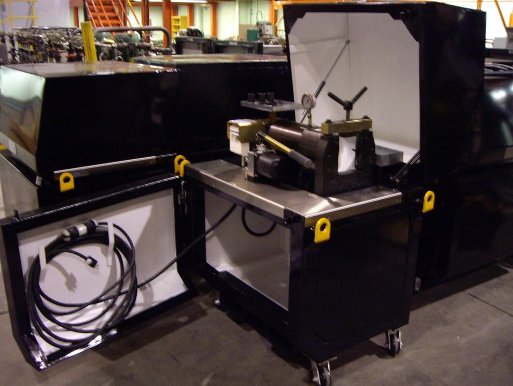
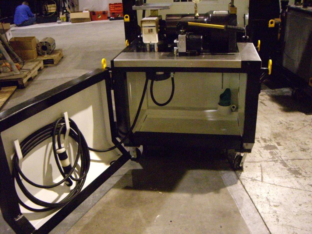
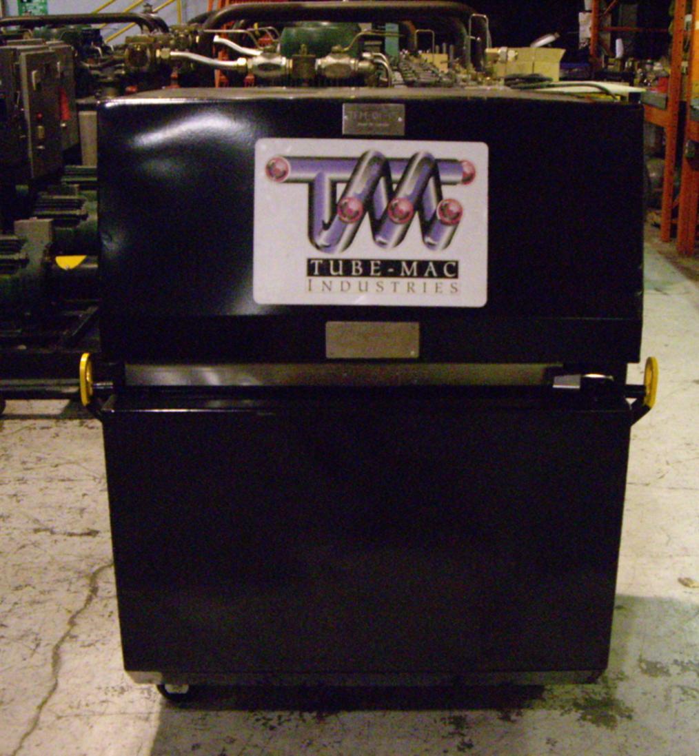
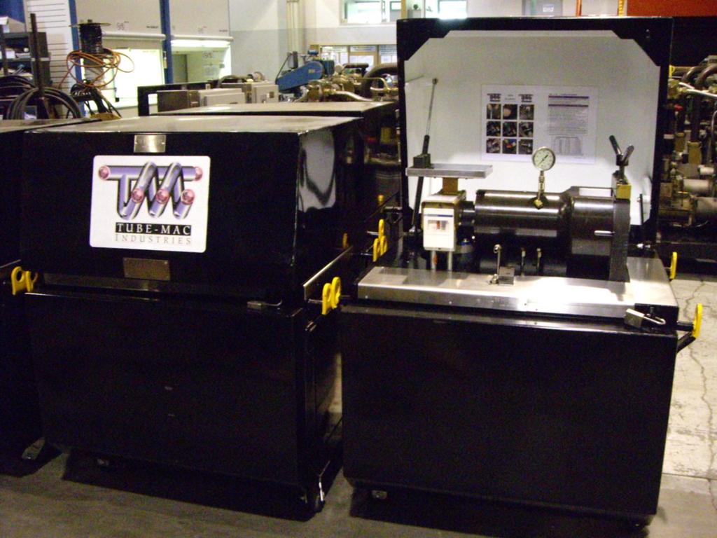
1 Tube-Mac Flaring Machine Information Package TFM 01, TFM-01-LS The purpose of the TUBE-MAC Industries TFM-01 and TFM-01-LS flaring machine is to produce a 37 flared pipe end in either cold drawn carbon steel or stainless steel pipe/tube. The TFM 01 flaring machine will produce a quality surface finish to meet the TUBE-MAC flare flange/cone insert. The TFM-01 is the standard design which has the greatest range of sizes for NPS, Metric and OD Tube. The new designed TFM-01-LS has been developed for heavier walled Pipe and Tube and is suggested for sizes such as 2 Sch.160 and 4 Sch.80 Pipe or 60x8mm and 115x7mm metric tube. Capacity: TFM-01 or TFM ` NPS from ½ thru 3 Sch. 80, 3-1/2 and 4 Sch. 40 Metric from 12mm thru 115mm x 7mm wall O.D. Tubes from ½ thru to 2 TFM-01-LS or TFM-01-LS-220(Low Speed) NPS from 1 Sch. 80 thru to 4 Sch.80 Metric from 38mmx 5mm thru to 115mmx 7mm Voltage: TFM /1Ø/60hz TFM /1Ø/50hz Weight: 920 lbs./ 417 kg Standard Construction (See Figures #1, 2 and 3 below): Hard rubber rotating Castors located at each bottom corner and a maximum width of 30 (760mm) allow for easy maneuvering of unit anywhere in a facility. (Fig.7) A 30ft (9m) power cord will reach any electrical outlet or generator (Fig.2)
2 Maintenance: Oil drain below flaring pin allows for oil to drain away from flaring area to a collection bottle located underneath in the storage area of the machine (Fig 3) Each unit comes with a pad lock to which locks the lid and front door shut to prevent damage or theft of tooling when not in use (Fig 5) Four (4) bright yellow lifting eyelets at each corner of the unit allow for easy lifting with a crane or forklift to any destination such as on board a ship or above/below ground working areas (Fig 6) Bottom of unit allows for storage of material or tooling that can be kept clean and safe behind the locked front door (Fig 3) Flaring Die and Pin shelf located beside operating switch allows for easy access and storage of flaring machine accessories. (Fig 1) Lid is easy to open due to a gas cylinder that helps with opening Handle of pump rotates 180 to allow operator to use either left or right hand while operating unit (Fig 1) One piece barrel and rigid framework makes for a durable and long lasting machine designed for a large range of flaring tube/pipe sizes (Fig 1) Training on the use of the TFM-01 machine is simply and easy when Tube-Mac qualified personnel train the operators on proper operating procedures and maintenance of the machine The TFM 01 flaring machine needs very little maintenance, as long as the machine is kept dry and clean. All bearings are of a standard type. Hydraulic fluid (Dexron III) must be checked occasionally and topped up as required. It is advised the flaring head be kept in the forward position when the machine is not in use, with the front end of piston flush with the front of cylinder. This is to protect the hydraulic cylinder against rust and dust. When replacing the cone bearings they can be removed easily with the threaded back plate (Part# TL-0112) which is behind the cone bearings, using slide hammer. When replacing the bearings it is imperative to always replace both bearings and pack each with high pressure grease. Using the provided diagram (located on each machine), position the bearings and back plate in the proper arrangement in the shaft support area. See Figure A for bearing alignment and configuration when changing out damaged shaft support bearings.
3 Figure A Shaft Support (Cone) Bearings Configuration for Bearing Change Back of Machine (Cylinder End) (See Fig.1) Front of Machine (Flaring End)

4
5 TFM-01 / TMF-01-LS FLARING PROCEDURE - PREPARATION - 1. Cut pipe to length with a bandsaw, or abrasive saw. Check the cut is square. 2. Deburr the OD with a file, the ID with an internal deburring tool. File the end of the pipe smooth, removing saw marks. 3. Clean the pipe, removing any cuttings/filings. Pull a clean lint free rag through the pipe to remove any dust/dirt. - FLARING - 4. Select the flaring cone for the pipe size, clean, and insert into the flaring head. See Consumable Parts List below for proper flare cone selection. 5. Select the die set for the OD size of pipe, and install one half into the die holder. Install the flange onto the pipe, place the pipe end into the lower die half, and support the other end of the pipe in a pipe stand. Place the upper die half into the die holder onto the end of the pipe. Hold the straight edge provided across the die surface, bringing the pipe end flush to the straight edge. Tighten the die clamp firmly. 6. Using the manual pump, advance the flaring head until the cone just comes into contact with the pipe. Lubricate the flaring cone with 90 weight gear oil, then energize the e-motor to begin the flaring head rotating. 7. Advance the flaring cone with short strokes of the manual pump until the desired flaring pressure is reached, maintain the pressure with short strokes of the manual pump as the flare is ironed until the there is no further pressure decay. The back of the flare should be contacting the die, and the flare is now complete. Shift the manual valve to release pressure from the flaring head as soon as the flare is complete. Continuing to iron the flare too long will cause a ridge to form in the bore of the pipe. Reference the chart below. 8. Retract the flaring head and remove the pipe from the dies. Wipe the flare clean and inspect. The surface should be smooth, polished, and free of cracks. 9. Remove any burrs from the dies on the outside of the pipe with a file. Set the flare flange cone into the pipe with a soft face hammer. There should be a gap of 1/16 1/8 (1-3mm) between the end of the flare and the shoulder of the cone, and the flange should slide freely over the flare. Notes: -It is advisable when flaring large quantities in a short period of time or heavy walled pipe to change out the flaring pin on each flare to prevent both the internal bearings and cones from overheating and premature failure -Pipe sizes 3 (90mm), 3-1/2 (100MM) and 4 (115MM) require faring twice, rotating the pipe 90 in the dies between flare operations to eliminate any tolerance issues on the flare -For flaring Schedule 160 Pipe or Heavy wall metric tube, see below for further instructions
6 Flaring Procedure for Schedule 160 Pipe (1 ½ thru 2 ½ ) and Heavy Wall Metric Tube (50mm thru 75mm) Use a good quality high temperature grease to pack the bearings. Repack the bearings every 6 flares. Will need at least a quantity of (4) TL-0012A flare pins (extra pins are required for rotating between each one to allow to cool) 1. Start with the pipe end.125 (3mm) (4mm) proud of the dies. 2. Clamp the pipe tightly in the dies. Mark the pipe at the back of the dies to see if there is any slippage while flaring. 3. Advance the TL-0012A flare pin/head and begin the 60bar. 4. Continue to advance the flare pin as long as the pressure continues to decay, increasing pressure in 10bar steps as pressure decay slows. Increase to maximum 110bar over maximum 1½ minutes total flaring time. 5. Retract flare pin/head, change pin (to allow cooling) and rotate pipe 90 in dies. 6. Flare 100bar, increasing to 110bar for maximum ½ minute total flaring time. 7. Flare is now complete. File any burrs/ridges on the OD of the pipe from the dies. 8. Flange should slide over the flare, with minimal clearance between OD of flare and ID of flange. FLARING PRESSURE and DURATION PIPE SIZE Pressure** Duration** 1/2 20MM bar 3-6 seconds 3/4 25MM bar 5-10 seconds 1 30MM bar 5-10 seconds 1-1/4 38MM bar 5-10 seconds 1-1/2 50MM bar 7-20 seconds 2 60MM bar 8-20 seconds 2-1/2 75MM bar seconds 3 90MM bar seconds* 3-1/2 100MM bar seconds* 4 115MM bar seconds* **Pressures and durations will vary with wall thickness and material strength** *Pipe sizes 3 (90mm), 3-1/2 (100MM) and 4 (115MM) require faring twice, rotating the pipe 90 in the dies between flare operations to eliminate any tolerance issues on the flare*
7 Consumable Parts List Pipe Flaring Pins Item # Part Number Description 1 TL-0011A 2 TL-0012A 3 TL-0013A 4 TL-0014A 5 TL-0017A 6 TL-0018A 1/2 to 1 Pipe 12mm to 30mm 1/2 to 1 OD Tube 1 ¼ to 1 ½ Pipe & 1 ½ thru 2 ½ Sch mm and 50mm and 60mm/75mm x 8mm< 1 ½ to 2 OD Tube 2 to 2 ½ / 60mm and 75mm 3 90mm 3 ½ 100mm 4 115mm Metric Tube Flaring Dies Item # Part Number Description 1 PFD-M12 12mm Pipe Die 2 PFD-M16 16mm Pipe Die 3 PFD-M20 20mm Pipe Die 4 PFD-M25 25mm Pipe Die 5 PFD-M30 30mm Pipe Die 6 PFD-M38 38mm Pipe Die 7 PFD-M42 42mm Pipe Die 8 PFD-M50 50mm Pipe Die 9 PFD-M60 60mm Pipe Die 10 PFD-M75 75mm Pipe Die 11 PFD-M90 90mm Pipe Die 12 PFD-M mm Pipe Die 13 PFD-M mm Pipe Die
8 NPS Pipe Flaring Dies Item# Part Number Description 1 PFD-050 ½ Pipe Die 2 PFD-075 ¾ Pipe Die 3 PFD Pie Die 4 PFD ¼ Pipe Die 5 PFD ½ Pipe Die 6 PFD Pipe Die 7 PFD ½ Pipe Die 8 PFD Pipe Die 9 PFD ½ Pipe Die 10 PFD Pipe Die Item# OD Tube Flaring Dies Part Number Description 1 TFD-050 ½ OD Tube Die 2 TFD-075 ¾ OD Tube Die 3 TFD OD Tube Die 4 TFD ¼ OD Tube Die 5 TFD ½ OD Tube Die 6 TFD OD Tube Die Spare Shaft Support Items Item # Part Number Description 1 TL-0112 Back Plate for bearing removal 2 TL-0113 Front Cover Plate for bearing 3 MHO-62-DA Snap ring # Inner Shaft Support Bearing 5 NJ2305E.TVP2 Outer Shaft Support Bearing 6 TL-0115 Rev A Complete bearing assembly (Items 1-5)
9 Spare Consumable Flaring Items Item # Part Number Description 1 Noga S-10 Replacement Reamer Blades 2 80w90 Gear Oil Gear Oil for Flaring Process 3 Extreme Pressure Grease Grease for Shaft Support Bearings 4 Dexron III Oil for Flaring Machine Reservoir *For all other inquires for spare parts please consult factory or local representative*
 Front of Machine (Flaring End)")
10 Figure #1 Back of machine (Cylinder End) Front of Machine (Flaring End)
11 Figure #2
12 Figure #3
13 Figure #4
14 Figure#5


15 Figure #6 Figure #7
Multihead Hydraulic Swaging Unit (MHSU) Setup and Operating Instructions
 Setup and Operating Instructions") Multihead Hydraulic Swaging Unit (MHSU) Setup and Operating Instructions Up to 1 in./25 mm MHSU with base 1 in./25 mm and over MHSU with base (also for use with 5/8 and 3/4 in. SAF 2507 TM super duplex
Multihead Hydraulic Swaging Unit (MHSU) Setup and Operating Instructions Up to 1 in./25 mm MHSU with base 1 in./25 mm and over MHSU with base (also for use with 5/8 and 3/4 in. SAF 2507 TM super duplex
COLD AIR INTAKE INSTALLATION INSTRUCTIONS
 COLD AIR INTAKE INSTALLATION INSTRUCTIONS # D760-0033 Fits: 2013-15 F01 B7, 750i & xdrive (N63TU engine) 2013-15 F02 B7L, 750Li & xdrive (N63TU engine) PARTS LIST Left and right carbon fiber air box lids
PRODUCT SERVICE MANUAL FOR CIG Lip Seal Double Pumps
 PRODUCT SERVICE MANUAL FOR CIG Lip Seal Double Pumps WARNING The Imo General Installation Operation, Maintenance, and Troubleshooting Manual, (No. SRM00046), as well as all other component manuals supplied
Installation Instructions
 Preparing your vehicle to install your brake system upgrade 1. Rack the vehicle. 2. If you don t have a rack, then you must take extra safety precautions. 3. Choose a firmly packed and level ground to
JUL 17 Rev M
 Hand Crimping Tool and Cable Preparation Kit; PN 59981-1 Instruction Sheet 408-6788 24 JUL 17 Rev M PROPER USE GUIDELINES Cumulative Trauma Disorders can result from the prolonged use of manually powered
VISUAL INDEX Equipment
 U R Hand Tube Benders Ratchet Hand Tube Bender 1 Hand Tube Bender BAV06/12 Combined Tube Bending & Cutting Tool BV06/18, BV20/25 Tube Bending Tools Benders R4-R5 R4 R5 R6 R6 Bender Capacity Guides Exactol
155 CARTRIDGE SINGLE SEAL
 MECHANICAL SEAL INSTALLATION INSTRUCTIONS 155 CARTRIDGE SINGLE SEAL SEAL INSTALLATION Preparation Determine if the pump is in good condition. A. Check the shaft or sleeve. 1. Remove all burrs and sharp
GS-37 FLARE FLANGE SYSTEM
 FLARING AND INSTALLATION INSTRUCTIONS GS-37 FLARE FLANGE SYSTEM REVISION FEBRUARY 2016 GS-37 GS-37 FLARE FLANGE SYSTEM Flaring and Installation Instructions Table of contents Introduction 3 GS-37 Connection
Maintenance. Daily. Shutdown Procedure. Periodically. During Freezing Temperatures
 Maintenance Daily Check the oil level and the condition of the oil. When the pump is operating, the oil in the pump housing gets warm and expands, filling into the oil reservoir. Depending on the type
GROUP 9 BOOM, ARM AND BUCKET CYLINDER
 GROUP 9 BOOM, ARM AND BUCKET CYLINDER 1. REMOVAL AND INSTALL 1) BUCKET CYLINDER (1) Removal Expand the arm and bucket fully, lower the work equipment to the ground and stop the engine. Operate the control
COLD AIR INTAKE INSTALLATION INSTRUCTIONS. # D Fits: F10 M5 # D Fits: F06/F12/F13 M6 PARTS LIST
 COLD AIR INTAKE INSTALLATION INSTRUCTIONS # D760-0035 Fits: 2013-15 F10 M5 # D760-0037 Fits: 2012-15 F06/F12/F13 M6 PARTS LIST (1) Left Carbon Airbox Lid (1) Right Carbon Airbox Lid (1) Left Carbon Snorkel
Low Profile Service Jack
 Low Profile Service Jack Operating Instructions & Parts Manual Model Number JSA200LCX Capacity 2 Ton MAC TOOLS INC. 2005 505 N. Cleveland Ave. Suite 200 Westerville, OH 43082 Printed in PRC Save these
SERIES G3DB/AG3DB ELEVATOR
 TM INSTRUCTIONS AND PARTS LIST SERIES G3DB/AG3DB ELEVATOR WARNING This manual, and GENERAL INSTRUCTIONS MANUAL, CA-1, should be read thoroughly prior to pump installation, operation or maintenance. SRM00059
Long Chassis Hydraulic Service Jacks
 Long Chassis Hydraulic Service Jacks Operating Instructions & Parts Manual Model Number Atd-7390 Atd-7391 Capacity 5 Ton 10 Ton Atd Tools Inc. 160 Enterprise Drive, Wentzville MO 63385 Printed in China
Parking brake Mechanical brake acting on rear wheels
 11 Brake System 11.1 General SPECIFICATIONS EJTC0010 Master cylinder Type Tandem type I.D. mm(in.) 20.64 mm (0.813 in.) Fluid level warning sensor Provided Brake booster Type Vacuum Boosting ratio 4.0
DISC BRAKE/DUAL MASTER CYLINDER CONVERSION. Tools, Equipment and Supplies Needed:
 Please take the time to read the enclosed instructions carefully. If you have any questions, call our Product Assistance personnel for clarification. It is important to note that these instructions contain
Maintenance Instructions
 General Note These instructions contain information common to more than one model of Bevel Gear Drive. To simplify reading, similar models have been grouped as follows: GROUP 1 Models 11, 0, 1,, (illustrated),,
I;! Anchor Lamina. l;! Lamina Components. Ball-Bearing Products. Check our website for the latest technical information.
 I;! Anchor Lamina l;! Lamina Components Ball-Bearing Products www.anchorlamina.com Check our website for the latest technical information. Ball-Bearing Components CONTENTS Ball-Bearing Operating Data &
Ball-Bearing Products
 Ball-Bearing Products www.daytonlamina.com Check our website for the latest technical information. Ball-Bearing Components Contents Ball-Bearing Operating Data & Design Selection... 2 Ball-Bearing Component
GENUINE PARTS INSTALLATION INSTRUCTIONS
 GENUINE PARTS INSTALLATION INSTRUCTIONS DESCRIPTION: APPLICATION: PART NUMBER: KIT-CARBON FIBER REAR SPOILER INFINITI Q50 T99J1 J5000 KIT CONTENTS: Item A B C D Qty. 1 4 1 1 Part Description Spoiler Assembly
Part 7 DO IT YOURSELF MAINTENANCE
 Part 7 DO IT YOURSELF MAINTENANCE Chapter 7 2 Engine and Chassis Checking the engine oil level Checking the engine coolant level Checking brake fluid Checking power steering fluid Checking tire pressure
INSTRUCTIONS FOR INSTALLATION OF THE CH-2 and CH-3 DRIVE UNIT TO AN ENGINE WARNING
 INSTRUCTIONS FOR INSTALLATION OF THE CH-2 and CH-3 DRIVE UNIT TO AN ENGINE WARNING! Never reach hands or other body parts in or near moving parts!! Maintain a safe distance from any fixed or moving propeller!!
250L Cartridge Dual Seal
 INSTALLATION, OPERATION AND MAINTENANCE INSTRUCTIONS 250L Cartridge Dual Seal Installation, Operation and Maintenance Instructions TABLE OF CONTENTS 1.0 Cautions...2 2.0 Transport and Storage...2 3.0 Description...2
Instruction Manual For DODGE. Airport Baggage Handling Systems Speed Reducers
 Instruction Manual For DODGE Airport Baggage Handling Systems Speed Reducers ABHS TXT109 - TXT115 - TXT125 ABHS TXT209 - TXT215 - TXT225 ABHS TXT309A - TXT315A - TXT325A ABHS TXT409A - TXT415A - TXT425A
GS 90 Flare Flange System Flaring and Installation Instructions
 Flaring and Installation Instructions 2 GS FLANGE SYSTEM Table of contents page Introduction...3 Selection of the pipe...4 Cutting of the pipe...5 Cleaning operations before flaring...6 Clamping the pipe...6
12. FRONT WHEEL/FRONT BRAKE/
 12 12 12-0 SERVICE INFORMATION... 12-1 FRONT BRAKE... 12-7 TROUBLESHOOTING... 12-2 FRONT SHOCK ABSORBER... 12-18 STEERING HANDLEBAR... 12-3 FRONT FORK... 12-21 FRONT WHEEL... 12-4 SERVICE INFORMATION GENERAL
GMR-S and GMR40-S Disc Brake Caliper - Spring Applied, Air Released
 (GMR) 9 (GMR) ø GMR-S and GMR-S Disc Brake Caliper - Spring Applied, Air Released DB Nominal dimensions given. For specific dimensions please contact Twiflex Limited. For GMR Mk caliper details see DB
INSTALLATION INSTRUCTIONS
 INSTALLATION INSTRUCTIONS PERFORMANCE AT THE WHEELS KIT W120-22, W120-23 1964 1/2-69 MUSTANG Thank you for choosing STAINLESS STEEL BRAKES CORPORATION for your braking needs. Pleases take the time to read
WINCHMAX. Hydraulic Winch Instructions b b b
 WINCHMAX Hydraulic Winch Instructions 1010001b 1510001b 2010001b Safety warnings and precautions WARNING: When using the tool, basic safety precautions should always be followed to reduce the risk of personal
Hydraulic Hand Crimping Tool, PN
 Hydraulic Hand Crimping Tool, PN 59974-1 Instruction Sheet 408-6757 19 JUN 17 Rev G PROPER USE GUIDELINES Cumulative Trauma Disorders can result from the prolonged use of manually powered hand tools. Hand
Maintenance Information
 16573347 Edition 2 February 2014 Air Grinder Series 88H Maintenance Information Save These Instructions Product Safety Information WARNING Failure to observe the following warnings, and to avoid these
POMPE AUTOADESCANTI SELF-PRIMING ELECTRO PUMP ACM DISASSEMBLY AND ASSEMBLY INSTRUCTIONS FOR MULTISTAGE SELF-PRIMING PUMPS
 POMPE AUTOADESCANTI SELF-PRIMING ELECTRO PUMP ACM DISASSEMBLY AND ASSEMBLY INSTRUCTIONS FOR MULTISTAGE SELF-PRIMING PUMPS Ed. 02/2011 5 WARNING These instructions are for the maintenance personnel for
mêçéìäëáçå=íê~áåáåö=ëüáéó~êçë propulsion training shipyards
 mêçéìäëáçå=íê~áåáåö=ëüáéó~êçë 1 Subjects: Introduction of Installation Planning Instructions (IPI). Purpose of training. Activity & responsibility list. Potential risks during assembling / mounting of
4.2 WATER PUMP (GEAR CASE MOUNTED AND LATER) (GCM)
 (GCM)") SERIES 60 SERVICE MANUAL 4.2 WATER PUMP (GEAR CASE MOUNTED - 1991 AND LATER) (GCM) The centrifugal-type water pump circulates the engine coolant through the cooling system. The pump is mounted on the rear
SERIES 60 SERVICE MANUAL 4.2 WATER PUMP (GEAR CASE MOUNTED - 1991 AND LATER) (GCM) The centrifugal-type water pump circulates the engine coolant through the cooling system. The pump is mounted on the rear
Tube Remover and Installer. and Installer Used for servicing Ford systems produced after Screen Extractor. Ford Aerostar Expansion
 gauges A/C FLUSH KIT Easy-to-use system removes refrigerant oil, moisture contaminants from system components lines during retrofitting compressor replacement. Kit includes rubber-tipped flush gun, canister
Installation Vertical Pump: Installation 'CM' and 'CDM' Style: Operation:
 Installation Vertical Pump: Gusher vertical end suction pumps with integral shaft is easily installed and put into service. With the one piece shaft design there is no couplings to align, no shims or no
The gear boxes can be run at the same speeds as the actuator models. Do not exceed torque ratings.
 1. What is the lifting torque required? The lifting torque for a single actuator depends on the load, the worm gear ratio, type of screw (machine cut or ball screw) and the pitch of the lifting screw.
12. FRONT WHEEL/FRONT BRAKE/
 12 4.5kgm 0.9kg-m 4.5kg-m 12-0 SERVICE INFORMATION... 12-1 HYDRAULIC BRAKE... 12-10 TROUBLESHOOTING... 12-2 FRONT SHOCK ABSORBER... 12-16 FRONT WHEEL... 12-3 STEERING HANDLEBAR... 12-19 FRONT BRAKE...
INTRODUCTION GENERAL GUIDELINES ATTACHING THE DRIVE PARTS
 INTRODUCTION Kretzschmar DC motors are of substantialy designed and manufactured to high standards. These motors will work satisfactorily for many years as long as they are maintained following the instructions.
PINS & BUSHINGS METRIC
 www.danly.com TRUSTED SOLUTIONS AND INNOVATION PINS & BUSHINGS METRIC www.danly.com PINS & BUSHINGS METRIC CONTENTS General Information 1 Plain & Ball Bearing Guide Posts Press Fit Guide Posts 2 Demountable
DIE DESIGN AND CONSTRUCTION SPECIFICATIONS STAMPING - EUROPE GENERAL INFORMATION CAM DIES
 GENERAL INFORMATION 1. ANGLE OF CAM SLIDE AND DRIVERS ANGLE OF CAM SLIDE AND DRIVERS ARE TO BE DIMENSIONED ON THE DIE DESIGN. FOR DRIVER ANGLES SEE, PAGE 4-7. AVOID THE USE OF CAM ADAPTORS. IF THE CAM
LC I LIPPERT COMPONENTS DISC BRAKE SYSTEM FOR TRAILERS INSTALLATION, OPERATION & SERVICE MANUAL. Table of Contents
 LC I LIPPERT COMPONENTS DISC BRAKE SYSTEM FOR TRAILERS INSTALLATION, OPERATION & SERVICE MANUAL Table of Contents Introduction... 2 Safety Information... 2 Installation... 3 Solenoid Reversing Valves...
COLD AIR INTAKE INSTALLATION INSTRUCTIONS
 COLD AIR INTAKE INSTALLATION INSTRUCTIONS # D760-0030 Fits: 2007-10 135i (E82, E88; with N54 engine) 2007-08 335i/xi (E90) 2007-10 335i (E92, E93; with N54 engine) Congratulations for being selective enough
GS-90 FLARE FLANGE SYSTEM
 FLARING AND INSTALLATION INSTRUCTIONS GS-90 FLARE FLANGE SYSTEM REVISION JANUARY 2015 GS-90 GS-90 FLARE FLANGE SYSTEM Flaring and Installation Instructions Table of contents Introduction 3 Selection of
PINS & BUSHINGS METRIC
 PINS & BUSHINGS METRIC PINS & BUSHINGS METRIC CONTENTS PAGE NUMBER General Information 1 Plain & Ball Bearing Guide Posts Press Fit Guide Posts 2 Demountable Guide Posts 4 Automotive Straight Guide Posts
Table of Contents. Standard Taps
 Table of Contents Standard Taps Standard Taps--High Speed Steel Machine Screw Sizes... 3 Standard Taps--High Speed Steel Hand Taps (Fractional Sizes)... 5 Standard Taps--High Speed Steel Machine Screw
DISASSEMBLY. 1. INSTALL ENGINE TO ENGINE STAND FOR DIS- ASSEMBLY 2. REMOVE CYLINDER HEAD (See page EM 29)
") DISASSEMBLY EM67 EM9Q0. INSTALL ENGINE TO ENGINE STAND FOR DIS- ASSEMBLY. REMOVE CYLINDER HEAD (See page EM9). REMOVE WATER BYPASS PIPE Remove the nuts, bolts, water bypass pipe and gasket.. REMOVE THERMOSTAT
DISASSEMBLY EM67 EM9Q0. INSTALL ENGINE TO ENGINE STAND FOR DIS- ASSEMBLY. REMOVE CYLINDER HEAD (See page EM9). REMOVE WATER BYPASS PIPE Remove the nuts, bolts, water bypass pipe and gasket.. REMOVE THERMOSTAT
INSTRUCTIONS 1WARNING 6 SPEED TRANSMISSION SUPER KIT -J03481 REV General. Removal. Kit Number A
 INSTRUCTIONS -J03481 REV. 08-31-04 Kit Number 33100-03A 6 SPEED TRANSMISSION SUPER KIT General This kit fits 1990-1999 Softail and 1991-2000 Dyna model motorcycles. Requires separate purchase of cable
BRAKE SYSTEM Nissan 240SX DESCRIPTION BRAKE BLEEDING * PLEASE READ FIRST * BLEEDING PROCEDURES ADJUSTMENTS BRAKE PEDAL HEIGHT SPECS TABLE
 BRAKE SYSTEM 1990 Nissan 240SX 1990 BRAKE SYSTEMS Nissan Disc & Drum Axxess, Maxima, Pathfinder, Pickup, Pulsar NX, Sentra, Stanza, 240SX, 300ZX DESCRIPTION All brake systems are hydraulically operated
PACKING, HANDLING, TRANSPORTING AND STORING MOTORS
 PACKING, HANDLING, TRANSPORTING AND STORING MOTORS Make sure that the shaft of the motor is not loaded in any way and is protected from knocks. Axial loads or shocks may easily damage the bearings inside
PRODUCT SERVICE MANUAL FOR CIG Lip Seal & Weep Hole Design Single Pump
 PRODUCT SERVICE MANUAL FOR CIG Lip Seal & Weep Hole Design Single Pump WARNING The Imo General Installation Operation, Maintenance, and Troubleshooting Manual, (No. SRM00046), as well as all other component
Bray/ VAAS Slurry Series Knife Gate Valve 760/762/765/766/767/768 Series Operation and Maintenance Manual
 Bray/ VAAS Knife Gate Valve 760/762/765/766/767/768 Series Table of Contents Definition of Terms 1 Safety Instructions 1 Introduction 2 Unpacking 2 Storage 2 Installation 3 Commissioning 3 Cylinder-Operated
Hydraulic Clutch Jack
 Hydraulic Clutch Jack Operating Instructions & Parts Manual Model Number Atd-7404 Capacity 500 Lb. Atd Tools Inc. 160 Enterprise Drive, Wentzville MO 63385 Printed in China ATD7404-M0 05/07 Save these
HYDRAULICS. TX420 & & lower. Hydraulic Tandem Pump Removal. 4. Remove the LH side panel (Fig. 0388).
.") TX420 & 425 240000299 & lower 4. Remove the LH side panel (Fig. 0388). Hydraulic Tandem Pump Removal Note: Cleanliness is a key factor in a successful repair of any hydraulic system. Thoroughly clean all
TX420 & 425 240000299 & lower 4. Remove the LH side panel (Fig. 0388). Hydraulic Tandem Pump Removal Note: Cleanliness is a key factor in a successful repair of any hydraulic system. Thoroughly clean all
13. CRANKCASE/CRANKSHAFT/BALANCER/PISTON/CYLINDER
 13. CRANKCASE/CRANKSHAFT/BALANCER/PISTON/CYLINDER COMPONENT LOCATION 13-2 SERVICE INFORMATION 13-3 TROUBLESHOOTING 13-4 CRANKCASE SEPARATION 13-5 CRANKSHAFT 13-7 MAIN JOURNAL BEARING 13-9 CRANKPIN BEARING
Installation,Operation, and Lubrication Instructions SPEED REDUCERS ILDE-00 TYPE DE ENGINEERING SERVICE BULLETIN
 ENGINEERING SERVICE BULLETIN ILDE-00 D-90 TYPE DE SPEED REDUCERS Installation,Operation, and Lubrication Instructions This Engineering Service Bulletin is designed to enable users to obtain the best possible
Differential Bearings
 SECTION 205-02B: Rear Drive Axle/Differential Ford 8.8-Inch Ring Gear 2009 Mustang Workshop Manual IN-VEHICLE REPAIR Procedure revision date: 01/06/2010 Differential Bearings Special Tool(s) 2 Jaw Puller
Maintenance Instructions. World Leader in Modular Torque Limiters. JSE AEA Extruder Clutch
 World Leader in Modular Torque Limiters PROTECTING EQUIPMENT& MACHINERYYEARSInstallation and Maintenance Instructions JSE.5-0234AEA Extruder Clutch 1304 Twin Oaks Street Wichita Falls, Texas 76302 (940)
Heavy Duty Electric Hydraulic Pumps PN and
 ORIGINAL INSTRUCTIONS Heavy Duty Electric Hydraulic Pumps PN 69120-1 and 69120-2 Customer Manual 409-1950 27 SEP 16 Rev F SAFETY PRECAUTIONS AVOID INJURY READ THIS FIRST!... 2 1. INTRODUCTION... 3 2. DESCRIPTION...
INSTALLATION & OWNER S MANUAL
 Rev. L p. 1 of 16 INSTALLATION & OWNER S MANUAL V4262 CAMO (SOFT SIDED) CAB KIT INSTALLATION & OWNER S MANUAL The contents of this envelope are the property of the owner. Be sure to leave with the owner
INSTRUCTION MANUAL IM-422 For HTC/COUPLING ASSEMBLY HC-8088
 No Revision 2/22/18 INSTRUCTION MANUAL IM-422 HTC/COUPLING ASSEMBLY The Riverhawk Company reserves the right to make changes updating this document without dissemination or notice. The latest revision
Tools, Equipment and Supplies Needed:
 153-162 DISC BRAKE/DUAL MASTER CYLINDER CONVERSION Please take the time to read the enclosed instructions carefully. If you have any questions, call our Product Assistance personnel for clarifi cation.
SAI GM Series Piston Hydraulic Motor Crankshaft Design Radial Piston Motors
 SAI GM Series Piston Hydraulic Motor Crankshaft Design Radial Piston Motors www.chinawinches.cn (Dimension: inch) Brief Performance Table of Sai GM Series Piston Hydraulic Motor (Full range GM05- GM9 series)
Constant Contact Side Bearings Shop and Field Inspection Pocket Guide
 Constant Contact Side Bearings Shop and Field Inspection Pocket Guide THE SYSTEM IS THE SOLUTION Table of Contents 1.0 Introduction...................... 4 2.0 Model Identification................ 6 3.0
Differential Ring And Pinion
 SECTION 205-02B: Rear Drive Axle/Differential Ford 8.8-Inch Ring Gear 2009 Mustang Workshop Manual IN-VEHICLE REPAIR Procedure revision date: 01/06/2010 Differential Ring And Pinion Special Tool(s) 2 Jaw
LIFTING MECHANISM PART NO SRM 965
 LIFTING MECHANISM B60Z [A230]; B80Z [A233]; C60Z [A478]; C80Z [A479]; W60Z [A231]; W65Z [A229]; W80Z [A234]; B60Z AC [B230]; B80Z AC [B233]; C60Z AC [B478]; C80Z AC [B479] PART NO. 1500202 4000 SRM 965
PPC PRODUCTS PARTS LISTS CATALOG 2013
 PLASTIC PACKAGING COMPONENTS GROUP PPC PRODUCTS PARTS LISTS CATALOG 0 Quality Delivery Support SOLUTIONS A division of PHD PPCPARTS INDEX Page FACTORY REBUILD PROGRAM Using H Codes... Cylinders STRETCH
Model TC-20. Tube Cut-Off Machine. Operator s Manual REV H
 Model TC-20 Tube Cut-Off Machine Operator s Manual 90-2333 REV H Scientific Systems, Inc. 349 N. Science Park Road State College, PA 16803 www.ssihplc.com Phone: 800-441-4752 Fax: 814-238-7532 Email: sales@ssihplc.com
Service Kit
 Service Kit 753-05607 Date: Subject: Models Affected: April 17, 2009 (Revised 6/08/2009) Hydraulic Cylinder Seal Replacement XINGHUI 4.5 Cylinder 718-0769A Read through and understand these instructions
Hydraulic Transmission Jacks
 Hydraulic Transmission Jacks Operating Instructions & Parts Manual Model Number Atd-7435 Atd-7436 Atd-7437 Capacity 1100 Lb. 2000 Lb. 3000 Lb. Model Atd-7435 Model Atd-7436 Model Atd-7437 Atd Tools Inc.
MICRO WELD MODEL AUF-8 HEAVY DUTY FERROUS BUTT WELDERS MICRO PRODUCTS COMPANY SERVICE MANUAL
 MICRO WELD MODEL AUF-8 HEAVY DUTY FERROUS BUTT WELDERS MICRO PRODUCTS COMPANY SERVICE MANUAL 1 TABLE OF CONTENTS 1.0 SPECIFICATIONS 2.0 GENERAL OPERATING INSTRUCTIONS 3.0 BASIC OPERATING PARTS 4.0 BASIC
ASSEMBLY INSTRUCTIONS FOR SUPERLITE 6R PRO SERIES FRONT HUB KIT WITH DIAMETER VENTED ROTOR GENERAL MOTORS G BODY DISC SPINDLE
 ASSEMBLY INSTRUCTIONS FOR SUPERLITE 6R PRO SERIES FRONT HUB KIT WITH 1.88 DIAMETER VENTED ROTOR 1980-1987 GENERAL MOTORS G BODY DISC SPINDLE PART NUMBER GROUP 10-198 DISC BRAKES SHOULD ONLY BE INSTALLED
CLUTCH CONTENTS SERVICE DIAGNOSIS. (a) Worn or damaged disc assembly. (b) Grease or oil on disc facings. (c) Improperly adjusted cover assembly.
 Worn or damaged disc assembly. (b) Grease or oil on disc facings. (c) Improperly adjusted cover assembly.") CLUTCH CONTENTS -GROUP 6 Page CLUTCH HOUSING ALIGNMENT... 6 CLUTCH PEDAL FREE PLAY 1 CLUTCH RELEASE BEARING 5 CLUTCH RELEASE FORK... 5 CLUTCH SERVICING 2 PILOT BUSHING CRANKSHAFT TO TRANSMISSION DRIVE
CLUTCH CONTENTS -GROUP 6 Page CLUTCH HOUSING ALIGNMENT... 6 CLUTCH PEDAL FREE PLAY 1 CLUTCH RELEASE BEARING 5 CLUTCH RELEASE FORK... 5 CLUTCH SERVICING 2 PILOT BUSHING CRANKSHAFT TO TRANSMISSION DRIVE
FOX Racing Shox Bypass Technical Manual.
 FOX Racing Shox Bypass Technical Manual. The following technical manual will be using a 2.5 dia. shock with three tubes for descriptions and illustrations. Your shock may differ in the number of tubes,
Eaton. Repair Information. Model and Piston Motors Fixed Displacement, Valve Plate Design. Medium Duty Piston Pump NO.
 Eaton Medium Duty Piston Pump NO. 7-141 Repair Information Model 74318 and 74348 Piston Motors Fixed Displacement, Valve Plate Design Parts Drawing 8 1 2 3 4 5 6 5 4 7 22 23 Rear or Opposite side Porting
Performance Brake Caliper Guide Bushing Set Installation Guide
 Performance Brake Caliper Guide Bushing Set Installation Guide Proper service and repair procedures are vital to the safe, reliable operation of all motor vehicles as well as the personal safety of those
DB4604 GMR-SD and GMR40-SD Disc Brake Caliper - Spring Applied, Air Released
 DB464 GMR-SD and GMR4-SD Disc Brake Caliper - Spring Applied, Air Released Nominal dimensions given. For specific dimensions please contact Twiflex Limited. For GMR Mk 2 caliper details see DB 364 Air
SECTION 7 2 DO IT YOURSELF MAINTENANCE MR2 U. Engine and Chassis
 SECTION 7 2 DO IT YOURSELF MAINTENANCE Engine and Chassis Checking the engine oil level................................. 168 Checking the engine coolant level............................ 169 Checking brake
IN-VEHICLE REPAIR. Differential Bearings. Rear Drive Axle/Differential Ford 7.5-Inch Ring Gear. Special Tool(s)
") 205-02A-1 IN-VEHICLE REPAIR Differential Bearings Special Tool(s) Protector, Drive Pinion Thread 205-460 Special Tool(s) Installer, Differential Shim 205-220 (T85L-4067-AH) 205-02A-1 2-Jaw Puller 205-D072
205-02A-1 IN-VEHICLE REPAIR Differential Bearings Special Tool(s) Protector, Drive Pinion Thread 205-460 Special Tool(s) Installer, Differential Shim 205-220 (T85L-4067-AH) 205-02A-1 2-Jaw Puller 205-D072
INSTALLATION INSTRUCTIONS
 INSTALLATION INSTRUCTIONS PERFORMANCE AT THE WHEELS KITS W156-6 & W156-7 1965-74 MOPAR B & E BODY Thank you for choosing STAINLESS STEEL BRAKES CORPORATION for your braking needs. Pleases take the time
ASSEMBLY INSTRUCTIONS
 ASSEMBLY INSTRUCTIONS FOR DYNALITE PRO SERIES FRONT HUB KIT WITH.75 DIAMETER VENTED ROTOR 1980-1987 GENERAL MOTORS G BODY DISC SPINDLE PART NUMBER GROUP -508-B WARNING INSTALLATION OF THIS KIT SHOULD ONLY
Installation and Operating Instruction for Brake Caliper HW 150 HFA and HW 180 HFA E e
 Installation and Operating Instruction for Brake Caliper HW 150 HFA and HW 180 HFA E 09.736e Schaberweg 30-38 Phone +49 6172 275-0 61348 Bad Homburg Fax +49 6172 275-275 Germany www.ringspann.com info@ringspann.com
Module. Section 9. NOTE: This section applies to applicators with CC200 modules B Issued 6/01. Manual 42-CF200-CM-01
 Section 9 NOTE: This section applies to applicators with CC200 modules. 9-0 Table of Contents i Table of Contents Section 9 1. Introduction............................................... 9-1 2. Specifications.............................................
10" TABLE SAW Model
 April 2001 INDUSTRIAL 10" TABLE SAW Model 06014739 4000 Open for Tool Illustration Pos. Part Number Description {Qty} F/C Pos. Part Number Description {Qty} F/C 1 2 0 996 864 Motor Housing 71 2 2 0 996
Air Actuated Hydraulic Bottle Jacks
 Air Actuated Hydraulic Bottle Jacks Operating Instructions & Parts Manual Model Number Atd-7412 Atd-7420 Capacity 12 Ton 20 Ton Atd Tools Inc. 160 Enterprise Drive, Wentzville MO 63385 Printed in China
SIZES: HXT105 HXT205
 Parts Replacement Manual For HYDROIL TORQUE-ARM Speed Reducers Taper Bushed For Char-Lynn * H, S, T and 2000 Series 6B Spline Motors SIZES: HXT105 HXT205 WARNING: Because of the possible danger to persons(s)
D-15/G-15 Maintenance
 D-15/G-15 Maintenance NOTE: The numbers in parentheses are the Reference Numbers on the exploded view illustrations found later in this manual and in the Parts Manual. Daily Check the oil level and the
SERIES BCZ2D NOZZLE CYLINDER START-UP AND INFORMATION SHEET
 Model Number Definition SERIES BCZD NOZZLE CYLINDER START-UP AND INFORMATION SHEET IMPORTANT INFORMATION DO NOT DISCARD! Use this information sheet to assist with cylinder installation, setup and repair.
Overhaul Instructions. S100 Series Centrifugal Fire Pumps. Table of Contents F /22/02 1/19/18
 S100 Series Centrifugal Fire Pumps Overhaul Instructions Form No. F-1031 Section 4219 Issue Date 02/22/02 Rev. Date 1/19/18 Table of Contents Section Page Introduction 4 Ordering Repair Parts 4 Pump Models
Crank Scraper & Windage Tray for GM LS & Vortec Engines
 Crank Scraper & Windage Tray for GM LS & Vortec Engines 3.622 Stroke & 4.000 Stroke Engines Made in USA Important: Read these instructions in their entirety prior to installation. Rev 160614 Applications
Instruction Manual for HSPA Take-Up Units
 Installation Instruction Manual for HSPA Take-Up Units Warning: To ensure the drive is not unexpectedly started, turn off and lockout the power source before proceeding. Failure to observe these precautions
a. remove counterbalance valves, travel motors and travel drives
 * For further information, contact Caterpillar Service Technology Group. Start By: a. remove counterbalance valves, travel motors and travel drives 1. Remove the counterbalance valve. See, "Disassemble
UltraBig M&I Mechanical Installation
 P/N: 6410T0017 Rev: 5/01/2012 Version C UltraBig M&I Mechanical Installation Doors are UltraRugged, UltraReliable, UltraAffordable. ASSA ABLOY ENTRANCE SYSTEMS. All Rights Reserved 975-A Old Norcross Road,
MODELS: 07125A, 07126A, 07013A Page 1
 MODELS: 07125A, 07126A, 07013A 56043142 Page 1 Switch Replacement 1-Remove the two screws (14) securing the switch cover 2-Remove tape from switch to expose wiring connections 3-Disconnect all wires 4-Remove
FLEXIDYNE PH Couplings
 FLEXIDYNE PH s s:,,,,,, D, D, D These instructions must be read thoroughly before installing or operating this product. DESCRIPTION: dry fluid couplings are a unique concept to provide soft start and momentary
DESCRIPTION & OPERATION
 2004 BRAKES Disc - TSX DESCRIPTION & OPERATION WARNING: DO NOT use air pressure or a dry brush to clean brake assemblies. Avoid breathing brake dust. Use OSHA-approved vacuum cleaner for cleaning and collecting
NOTE: The burr on the slave piston bore will not affect the performance of the brake. It only affects the ability to reset the lash.
 SERIES 60 SERVICE MANUAL 12. Inspect slave piston bore for burrs at the depth where the slave piston contacts the adjusting screw. [a] If no burrs are found, proceed with inspection. [b] If burrs are found,
TIRES AND WHEELS 22-1 TIRES AND WHEELS CONTENTS
 ZJ TIRES AND WHEELS 22-1 TIRES AND WHEELS CONTENTS TIRES... 1 WHEELS... 7 TIRES INDEX DESCRIPTION AND OPERATION RADIAL-PLY TIRES... 2 REPLACEMENT TIRES... 3 SPARE TIRE TEMPORARY... 2 TIRE INFLATION PRESSURES...
Operation and Maintenance Instructions
 Hydratight Limited Bentley Road South Darlaston West Midlands WS10 8LQ United Kingdom Tel: +44 121 50 50 600 Fax: +44 121 50 50 800 E-mail: enquiry@hydratight.com Website: www.hydratight.com TOP COLLAR
SPECIFICATIONS TEST AND ADJUSTMENT SPECIFICATIONS SPECIFICATIONS ENGINE FD620D, K SERIES
 TEST AND ADJUSTMENT Engine Oil Pressure Sensor Activates............................... 98 kpa (14.2 psi) Oil Pressure While Cranking (Minimum).......................... 28 kpa (4 psi) Oil Pressure.....................................