SOLID STATE DIGITAL TIMER
|
|
|
- Jared Campbell
- 6 years ago
- Views:
Transcription
1 INSTRUCTION MANUAL For SOLID STATE DIGITAL TIMER MODEL SST-2 SERIAL NO. It is essential that this instruction book be read thoroughly before putting the equipment in service.
2 APPRECIATION We are indebted to those who have given their time and advice in the preparation of this instruction manual. It is MULTI-AMP Corporation's goal to continually improve its products and services to its customers. To that end, we welcome any suggestions or contributions our customer would care to offer. IMPORTANT The information and data contained within this instruction manual are proprietary with AVO MULTI-AMP Corporation. The equipment described herein may be protected by one or more U.S. letters patent. AVO MULTI-AMP specifically reserves to itself all rights to such proprietary information as well as all rights under any such patent, none of which is waived by the submission of this instruction manual to anyone. The recipient, if a Government agency, acknowledges that this instruction book and the equipment described were procured with "Limited Rights" to technical data as described in ASPR (b). Copyright AVO MULTI-AMP Corporation, 1975, 1978, 1987, 1989, 1990, 1992 Table of Contents Section Page
3 INTRODUCTION SAFETY PRECAUTIONS... 1 THEORY OF OPERATION... 2 Description of Controls... 2 INPUT VOLTAGE SELECTION... 4 Models With Input Selector Switch... 4 Models With Input Autotransformer... 4 Models Without Input Autotransformer... 5 PREPARATION FOR OPERATION... 6 Circuit connections... 6 Control Selection... 6 Timing Functions... 6 TEST PROCEDURES... 8 General Test Procedures... 8 SERVICE DATA... 9 Servicing... 9 Service and Repair Order Instructions Preparation for Reshipment Warranty Statement REPAIR DATA Basic Troubleshooting Power Input Chassis Assembly Timer Assembly Timing Errors Connection Point Identification Guide Wire Color Code Guide Parts Replacement PARTS LIST Model SST-2 Digital Timer PARTS LIST Part No. 3710A Timer Assembly ii
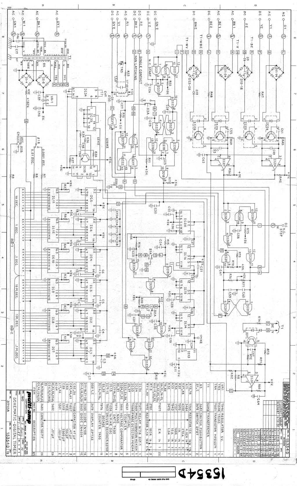
4 INSERT SCHEMATIC DRAWINGS Drawing No C, Figure 1 Model SST-2 With Autotransformer Drawing No C, Figure 2 Model SST-2 Without Autotransformer Drawing No C, Figure 3 Model SST-2 With Input Selector Switch Drawing No D Part No. 3710A Timer Assembly iii
5 SAFETY PRECAUTIONS WARNING The Multi-Amp Model SST-2 Timer is designed for use on energized circuits. For the safety of the operator and protection of the instrument, do not connect it to circuits that have voltages present beyond the limits of operation stated in the specifications. This includes circuits that could become energized during the course of a test procedure utilizing this instrument. CAUTION The input voltage of this instrument is selectable. All the units are shipped from the factory set up for operation from a nominal 115 volt source. If this unit is to be used on a 230 volt source, refer to the INPUT VOLTAGE SELECTION section for proper instructions. For safe operation, it is absolutely essential that the operator properly and effectively ground (earth) the test set. This is accomplished by connecting the input line cord to a properly grounded receptacle. The test leads provided with the Model SST-2 are sufficiently insulated to withstand any voltage encountered within the specified operating voltages of the instrument as stated in the specifications. For the safety of the operator, if test leads of another type or manufacture are used, the insulation rating and quality should be at least equal to that of the leads provided. 1
6 THEORY OF OPERATION Description of Controls This section of the instruction manual describes the functions of all the various control switches, etc., which are located on the front panel of the Model SST-2. All controls are clearly marked and logically grouped so that continual reference to the instruction manual should not be necessary after the operator has become acquainted with the operation of the instrument. Input Cord Input Power POWER ON/OFF Switch Fuse F1 Timer Display RESET Button SEC/HZ Switch A line cord with a standard three-prong grounded plug is provided for connection of the timer to a suitable source of power. Each Model SST-2 is shipped from the factory with the input power set up for 115 volt (±10%) operation. Should it be desired to change this timer to operate from a 230 volt (±10%) source of supply, refer to the INPUT VOLTAGE SELECTION Section for details. Used to energize the power input of the timer. Protects the input power system of the timer. Illuminates whenever the power input to the timer is energized, and indicates elapsed time. Resets timer logic and resets display to zero. Selects mode of count, either in cycles or seconds. NOTE: The timer will not stop when the maximum count of any range is reached. It will roll over to zero and continue counting. If the timer is observed carefully, timing beyond maximum range can be performed..01/.0001 Switch Selects the range of the seconds mode, either 0.01 to seconds or to seconds. NOTE: Never change the SEC/Hz or.01/.0001 switch positions during a timing operation or an error will result. START Binding Posts The start signal selected by the START Selector Switch is applied to these binding posts. 2
7 STOP Binding Posts START LATCH ON/OFF Switch STOP LATCH ON/OFF Switch START/STOP Selector Switches The stop signal selected by the STOP Selector Switch is applied to these binding posts. This two position switch is used in conjunction with the START Selector Switch and START Binding Posts to control the starting of the counter. When "ON", the START LATCH allows timing to be initiated by any start gate and to be stopped only by the stop gate selected with the STOP Selector Switch and applied at the STOP Binding Posts. When "OFF", the START LATCH allows timing to be initiated by any start gate and to be stopped when the start gate is reversed (such as timing the closing and opening of a single contact when measuring the trip-free operating time of a circuit breaker). This two position switch is used in conjunction with the STOP Selector Switch and STOP Binding Post to control the stopping of the counter. When "ON", the STOP LATCH allows timing to be stopped at the first operation of any stop gate (thus ignoring contact bounce, for example). When "OFF", the STOP LATCH allows timing to be stopped by any stop gate and then restarted if the stop gate reverses (provided the start gate is still energized) and then again stopped when the stop gate is again energized. Two identical, independent, four-position switches are provided for selection of start and stop gates. The left switch is used to select the start gate operating mode while the right switch is used to select the stop gate mode. The following modes are provided for both the start gate and the stop gate. a. Dry Contact Closure (N.O. DRY CONTACTS). Timer starts or stops at the closure of a normally open contact or upon conduction through a semi-conductor device such as a scr, triac or transistor. b. Dry Contact Opening (N.C. DRY CONTACTS). Timer starts or stops at the opening of a normally closed contact or when conduction through a semi-conductor device such as a scr, triac or transistor is interrupted. c. Application of AC or DC Potential (AC/DC APPLIED). Timer starts or stops when an AC potential (3-300 volts rms) or DC potential (5-300 volts) is applied. d. Removal of AC or DC Potential (AC/DC REMOVED). Timer starts or stops when an AC potential ( volts rms) or DC potential (5-300 volts) is removed. 3
8 INPUT VOLTAGE SELECTION All Model SST-2 timers are manufactured as dual voltage (115/230V) units and are shipped from the factory with the input voltage set for nominal 115 volt operation. When it is desired to operate the Model SST-2 from a nominal 230V power source, it is necessary for the operator to change the input voltage by one of three different methods, depending upon the age of the SST-2. The newest model uses a selector switch (see Models with Input Selector Switch). Earlier Model SST-2 timers were built with the voltage selection made directly to the timer assembly by moving a wire at the terminal block (TB1). Later models have an input autotransformer to provide more power for the auxiliary relay and to standardize the timer assembly that is used. If the transformer is present, DO NOT change any of the connections at the terminal block. Since all new units shipped from the factory are connected for nominal 115V operation, a ½ ampere fuse is installed in the input fuse holder. If the input voltage tap is changed for 230V operation, it is necessary to replace the ½ ampere fuse with a ¼ ampere fuse. The reverse procedure is necessary when converting from 230V operation to 115V operation. Five spare fuses of each current rating are supplied with each new unit. The following procedures are provided for changing the input voltage of the Model SST-2. There is a procedure for each of the three types of input power systems described above. Models With Input Selector Switch Refer to Schematic Drawing 15498C, Figure 3, Section VI. The Input Selector Switch is located in the front left corner of the lead compartment. To change the input voltage of the unit, remove the instrument from the enclosure by removing the four mounting screws located on the back of the enclosure and slide the instrument out until the switch is accessible. Insert a screwdriver blade in the slot of the voltage selector and move it to the desired position. The voltage selected is marked on the recessed area of the selector. Slide the instrument into the enclosure and install the four mounting screws. Insert the correct amperage fuse in the fuse holder for the input selected. Models With Input Autotransformer Refer to Schematic Drawing 15498C, Figure 1, in Section VI. To change the input voltage of the unit, remove the instrument from the enclosure by removing the four mounting screws located on the back of the enclosure and slide the instrument out. Locate the autotransformer mounted adjacent to the timer assembly enclosure. A terminal strip is attached to one of the transformer mounting screws. There are two wires, one black and one black with red tracer, connected to one terminal. This is the 115V tap. The red wire connected to another terminal is the 230V tap. There is a jumper connected between a terminal with a brown wire (common) and the 115V tap. This is referred to as Connection "A" for 115V operation. 4
9 To convert the unit to 230V operation, disconnect the jumper from the 115V tap (terminal with one black wire and one black wire with red tracer), and reconnect the jumper to the 230V tap (terminal with red wire). This is referred to as Connection "B" for 230V operation. To convert the unit back to 115V operation, simply reverse the procedure by moving the jumper to the 115V tap (Connection "A") as described above. Return the instrument to the enclosure and install the four mounting screws. Insert the correct amperage fuse in the fuse holder for the input selected. Models Without Input Autotransformer Refer to Schematic Drawing 15498C, Figure 2, in Section VI. To change the input voltage of the unit, remove the instrument from the enclosure by removing the four mounting screws located on the back of the enclosure and slide the instrument out. Locate the black wire and gray wire (from the Timer Cable #1) which terminate at the left side of the terminal block (TB1) located on the right side of the chassis (when viewing the unit from the back). The black wire is the 115V tap and the gray wire is the 230V tap. The black wire on the right side of TB1 is connected opposite of the black wire on the left side of TB1 for 115V operation and is referred to as Connection "A" (See CAUTION note). To convert the unit to 230V operation, disconnect the black wire on the right side of the terminal block and connect it to the terminal on the right side of the terminal block opposite the gray wire. This is referred to as Connection "B" for 230V operation. To convert the unit back to 115V operation, simply reverse the procedure by moving the black wire back to the 115V tap (Connection "A") side which is described above. Return the instrument to the enclosure and install the four mounting screws. Insert the correct amperage fuse in the fuse holder for the input selected. CAUTION There may be two wires present at the terminal on the right side of the terminal block on very early models. If they are both black, disconnect both wires and separate them. Using an ohmmeter, check continuity between the black wire terminating at the fuse holder (F1) and one of the two black wires that have been disconnected. The one that reads continuity is the wire that is to be moved. Mark this wire for future reference. Regardless of color, the other wire is a relay wire and must remain terminated opposite the black wire on the left side of the terminal block. 5
10 PREPARATION FOR OPERATION Circuit connections Test all circuits the SST-2 START/STOP Binding Posts are to be connected to. If dry contact operation is to be used, be sure the circuit will not become energized when the device to be tested operates. If energized contact operation is to be used, be sure that voltage levels that are or will be present on the test circuits will not exceed the rating of the instrument. The voltage levels present must also be within the operating range of the START/STOP circuits or a timing error will result. The test leads provided are sufficiently insulated for test voltages within the specifications of the instrument. Control Selection The Model SST-2 provides a wide variety of timing functions. The operator must determine what type of timing conditions will be presented and select the appropriate functions that will permit the Model SST-2 to perform the desired tests. This can be best accomplished if the operator is thoroughly familiar with the various functions of the unit prior to its use by reviewing the Description of Controls and the Timing Functions sections of the manual. Timing Functions The timing functions are explained in the Operating Procedures and Description of Controls. However, they can be best understood by the following method: 1. Connect the input line cord to the correct power source. 2. Connect one pair of test leads to the START Binding Posts and one pair to the STOP Binding Posts. 3. Select the N.O. DRY CONTACTS position with the START and STOP Selector Switches. 4. Select any timer mode and range desired. 5. Switch both the START and STOP LATCH Switches to the OFF position. 6. Switch the POWER ON. The timer display will light. 7. Press the timer RESET Button. NOTE: Always reset the timer prior to beginning a timing test. This is especially important when any control functions are changed. 8. Touch the START test leads together to start the timer. Separate them and the timer will stop. The timer will continue to start and stop every time the START test leads are touched together and separated. NOTE: The STOP gate will not stop the timer with above control selections. 9. Put the START LATCH Switch in the ON position. 10. Reset the timer. 6
11 11. Touch the START leads together and then separate them. The timer will continue to run. 12. Touch the STOP leads together. The timer will stop. Separate the STOP leads. The timer will remain stopped. 13. Touch the START leads together. The timer will restart and continue counting until the STOP leads are again touched together. 14. Stop the timer. 15. Put the STOP LATCH in the ON position. 16. Reset the timer. 17. Start the timer by momentarily touching the START test leads together. The timer will start and continue to run. Momentarily touch the STOP test leads together. The timer will stop. Attempt to restart the timer without pressing the RESET button. The timer will remain stopped. 18. Reset the timer and repeat the test. This selection will provide starting and stopping from momentary contact closure. 19. Put the START LATCH in the OFF position. 20. Reset the timer. 21. Repeat the test as described in Step 8. Even with the STOP LATCH in the ON position, the STOP gate will not stop the timer. Steps 1-21 demonstrate all the basic starting and stopping functions of the Model SST-2. The N.C. DRY CONTACTS selection functions opposite of the N.O. DRY CONTACTS selection. Rather than touching the leads together to start or stop the timer they are separated, simulating a closed contact moving to the open position. Similarly, AC/DC APPLIED acts like an open contact moving to the closed position, and AC/DC REMOVED acts like a closed contact moving to the open position. Experiment with the different START/STOP functions and various combinations of them, including the LATCH functions, to fully understand what the timer will do in a desired test situation. It is important to note that incorrect timer functioning during a test is generally caused by either an incorrect control selection, not resetting the timer prior to initiating the test or not properly identifying the control points used in the test scheme. 7
12 TEST PROCEDURES There are literally hundreds of testing applications for the Model SST-2. There are 48 control function combinations and three timer mode selections. Once the operation of the Model SST-2 is thoroughly understood, the operator can easily construct a test procedure for each application encountered. Various procedures could be suggested by Multi-Amp, but the correct method of timing various devices depends entirely on the recommendations of the manufacturer of the device and the preferences of the operator or the organization that sets the standards for performing such tests. Therefore, a General Test Procedure has been provided to guide the operator. It is recommended that the operator add appropriate test procedures to the Test Procedures section as each situation is encountered. If various specific or standard procedures are already available, adding copies of them to the Test Procedures Section for convenient field reference is suggested. General Test Procedures Refer to all cautionary statements and other instructions prior to making any test connections. 1. Connect the instrument to a suitable source of power. Refer to the Input Voltage Selection section for details. 2. Switch the POWER ON/OFF Switch ON. The timer display should light. 3. Switch the START Selector Switch to the desired position for the START function to be used. 4. Switch the START LATCH ON/OFF Switch to the desired position. If it is desired to use a separate STOP function to stop operation of the timer, switch the START LATCH ON. If it is desired to use the reversal of the START signal to stop the timer (such as timing the closing and opening of single contact when measuring the trip-free operating time of a circuit breaker), switch the START LATCH OFF. 5. When it is desired to use a separate stop gate signal to stop the timer, switch the STOP Selector Switch to the desired position. 6. Switch the STOP LATCH ON/OFF Switch to the desired position. If it is desired to have the timer stop upon the first stop signal only, switch STOP LATCH ON. If it is desired to have the timer restarted if the stop signal reverses (as when measuring contact bounce), switch STOP LATCH OFF. 7. Switch the SEC/HZ Switch to the desired mode. If the seconds mode is used, switch the 0.01/ Switch to the desired range. 8. Make necessary connections to the START and STOP Binding Posts. 9. When the appropriate start and stop signals are applied, the display indicates the elapsed time of the test. NOTE: Always reset the timer before each timing test to assure all logic circuits are in the correct state, even when the display reads zero. This is especially recommended when any switch positions are changed. 8
13 SERVICE DATA Servicing The timer utilizes straightforward circuits and components which require little or no service except for routine cleaning, tightening of connections, etc. The timer should be serviced in a clean atmosphere away from energized electrical circuits. The following maintenance is recommended: 1. Open the unit every six months and examine for: a. dirt b. moisture c. corrosion 2. Remove dirt with dry, low pressure, compressed air. 3. Remove moisture as much as possible by putting the test set in a warm, dry environment. 4. As corrosion may take many forms, no specific recommendations can be made for its removal. 9
14 Service and Repair Order Instructions If factory service is required or desired, contact the factory for return instructions. A Repair Authorization (RA) number will be assigned for proper handling of the unit when it arrives at the factory. If desired, a letter with the RA number and instructions can be provided. Provide the factory with model number, serial number, nature of the problem or service desired, return address, your name, and where you can be reached should the factory need to contact you. If desired, you may also provide a purchase order number, cost limit, billing, and return shipping instructions. National Institute of Standards and Technology (NIST) traceable calibration and certification of two types is available, if desired, at additional cost. Class One: Class N: A certificate is provided verifying the traceability and calibration of the equipment. That which is required for nuclear power plants. A certificate of traceability and calibration along with "as found" and "as left" data are provided. If an estimate is requested, provide the name and contact information of the person with approval/disapproval authority. Pack the equipment appropriately to prevent damage during shipment. If a reusable crate or container is used, the unit will be returned in it if it is in suitable condition. Put the RA number on the address label of the shipping container for proper identification and faster handling. NOTE: Ship the equipment without instruction manuals or nonessential items such as test leads, spare fuses, etc. These items are not needed to conduct repairs. Preparation for Reshipment Save the shipping container for future use. The shipping container your unit came in is designed to withstand the normal bumps and shocks of shipping via common commercial carrier. For example, you may wish to reship your unit to Multi-Amp for annual calibration certification. 10
15 Warranty Statement Multi-Amp Corporation warrants to the original purchaser that the product is free of defects in material and workmanship for a period of one (1) year from date of shipment. This warranty is limited and shall not apply to equipment which has damage, or cause of defect, due to accident, negligence, improper operation, faulty installation by the purchaser, or improper service or repair by any person, company or corporation not authorized by Multi-Amp Corporation. Multi-Amp Corporation will, at its' option, either repair or replace those parts and/or materials that it deems to be defective. Any costs incurred by the purchaser for the repair or replacement of such parts and/or materials shall be the sole responsibility of the original purchaser. THE ABOVE WARRANTY IS IN LIEU OF ALL OTHER WARRANTIES, EITHER EXPRESSED OR IMPLIED ON THE PART OF THE MULTI-AMP CORPORATION, AND IN NO EVENT SHALL THE MULTI-AMP CORPORATION BE LIABLE FOR THE CONSEQUENTIAL DAMAGES DUE TO THE BREACH THEREOF. 11
16 REPAIR DATA It is not always necessary to return the complete instrument to the factory for repair. To save time and reduce costs, basic troubleshooting information has been provided to guide the technician to the possible source of a problem. At least half of all problems experienced with the Model SST-2 are minor and can be corrected with a single replacement part. More extensive problems can be corrected by replacing printed circuit board assemblies in the timer assembly. Repairs beyond the scope of the troubleshooting guide should be referred to the Service Department at Multi-Amp or handled through the Multi-Amp Representative. If the unit is still within the original warranty period, or limited warranty period following factory servicing, the factory must be contacted before attempting any repairs or the warranty will be void. The troubleshooting information relies on the schematic drawings provided with this manual and are normally sufficient for this purpose. Be advised that the drawings are applicable to the unit the manual was supplied with at the time of purchase. If the instruction manual was obtained separately, the drawings will be applicable to the equipment in production at that time and may not duplicate the unit being repaired. It is recommended that if a difference between the unit and the drawings exists, the technician should contact the factory before attempting repairs. Provide the Multi-Amp part number for the part or assembly in question and the serial number of the SST-2 when making inquiries. Two guides in this section are provided to assist the technician in following the schematic drawings. The Wire Color Code Guide identifies the color codes used on the drawings that correspond to the wiring in the unit. The Connection Point Identification Guide identifies the connection points and input circuit functions of drawing 15354D. The guides should be reviewed before using the schematics. Basic Troubleshooting WARNING It is necessary to energize the SST-2 to properly troubleshoot some parts of the circuitry. The technician must take all applicable safety precautions for working on energized circuits. NOTES Before suspecting a failure in the instrument, review the Timing Functions, Description of Controls and Timing Variables sections to ensure that the problem is not a result of operating error. Preliminary testing of the SST-2 within its specified limits can help determine if a malfunction actually exists, identify the type of malfunction and define the general area of the failure. Failures often occur from components simply wearing out from use. This of course is normal, but occasionally they wear out prematurely or fail as a result of conditions occurring during operation of the instrument. Common causes of malfunctions, other than improper operation, are incorrect power input (voltage above or below specified limits), incorrect test signal voltages (outside of the specified AC/DC Applied/Removed limits), and contact or circuit resistance too great for the Dry Contact gates to operate properly. These causes can affect either chassis assembly parts, timer assembly parts, or both. Power Input 12
17 Input voltage affects the whole unit and may or may not cause permanent damage if voltage is incorrect. These problems can often be corrected by simply using a better source of input power. The rated voltage limits are to 126.5V for the nominal 115V tap and 207 to 253V for the nominal 230V tap, 50 or 60 HZ. Some symptoms are as follows: 1. Low voltage: Weak display, latch relay is sluggish, Start/Stop gates function erratically, timing inconsistent, fuses fail. Low voltage problems are more obvious on 50 HZ systems. 2. High voltage: Varistor failure, timer assembly power supply failure, input autotransformer failure. Chassis Assembly Refer to Schematic Drawing 15498C and Wire Color Code Guide. Basic troubleshooting of the main chassis and front panel components are as follows. Problems caused by a malfunction in the timer assembly will be covered separately. 1. No power: Check power source, input fuse, line cord, voltage at autotransformer, power switch, wiring and connections at TB1. 2. Start/Stop Latch malfunction: Auxiliary relay contacts dirty or relay defective, varistor failure, latch switch failure (Notes: Latching occurs with switch contacts open). 3. Start/Stop function problems: START and/or STOP Selector Switch faulty, dirty contacts, broken jumpers or wiring, bad connections, resistor failure. Timer Assembly Refer to Schematic Drawing 15354D, Wire Color Color Code and Connection Point Identification Guide. If all the items external of the timer assembly are in proper order, then the problem exists within the timer assembly itself. The P/N 3710A Timer Assembly is constructed of five basic parts: 1. Timer Start/Stop PCB Assembly (P/N 4121) 2. Logic PCB Assembly (P/N 4190) 3. Display PCB Assembly (P/N 4192) 4. Mother PCB Assembly (P/N 4191) 13
18 5. Timer Enclosure (which includes the input transformer, voltage regulator and lens/bezel assembly). NOTE: The onboard timer assembly transformer is also designated T1 and is not to be confused with the chassis autotransformer. The complete timer assembly can be removed from the front panel of the SST-2 by disconnecting Cables #1 and #2 from the terminal strips, removing the four screws in the display panel and lifting the timer out from the back side of the front panel. It is usually recommended that the complete timer assembly be returned for factory repair if found to be defective. Then any improvements that have been made in the assembly can be incorporated into it during repair and servicing. Some basic troubleshooting can pinpoint problems to the approximate cause, if it is desired to repair the P/N 3710A on site. Basic troubleshooting is as follows: 1. No display when the SST-2 is energized: Power supply failure, defective display IC's, defective components on or connections to P/N 4192 PCB. See Power Supply malfunctions. 2. Weak or defective display: Poor supply voltage, defective display(s), defective components on P/N 4192 PCB. See Power Supply malfunctions. 3. Problems with SEC/HZ or.01/.0001 range selection: Defective selector switch(es), defective circuit resistors or defective IC's on P/N 4190 PCB or P/N 4192 PCB. 4. Problems with timer reset: Defective pushbutton switch on P/N 4192 PCB or defects in P/N 4190 PCB. 5. Counting problems: a. Counting errors in seconds but not cycles or vice versa: Defects in P/N 4190 PCB. b. Counting errors in seconds only: Defective IC 33-35, TR4 or related parts on P/N 4191 PCB, defective IC 32 or 37 on P/N 4121 PCB, T1 failure, defective 16MHz oscillator (IC13). Read counting frequency at pin 11 on IC13. c. Counting errors in both seconds and cycles: Defects in P/N 4121 Start/Stop PCB, defects in P/N 4190 PCB. 6. Latch malfunctions: Note: The latch relay (X1) is controlled by the timer assembly. Therefore, relay malfunctions can be caused by timer malfunctions. a. Latch relay (X1 on chassis) not functioning: Defective relay (X1), defective triac (TR5), or relay (IC36) on P/N 4191 PCB. 14
19 b. No Start/Stop Latch: Defective TR5 or IC36, diode D30, defects on P/N 4190 PCB. c. No Start Latch only: Defective IC18, or related parts P/N 4190 PCB. d. No Stop Latch only: Defective components, P/N 4190 PCB. 7. Start/Stop malfunctions: a. All Start modes malfunction: Defective IC24 on P/N 4121 PCB, reset failure, stop mode failure. b. All Stop modes malfunction: Defective IC27 on P/N 4121 PCB, reset failure. c. AC/DC Applied/Removed Start malfunction: Defective D11-14, IC26 on P/N 4121 PCB. d. N.O./N.C. Dry Contact Start malfunction: Defective R47, D9, D11-18, IC25 on P/N 4121 PCB, T1 failure. e. AC/DC Applied/Removed Stop malfunction: Defective D21-24, IC29 on P/N 4121 PCB. f. N.O./N.C. Dry Contact Stop malfunction: Defective R48, D19, D25-28, IC28 on P/N 4121 PCB, T1 failure. g. N. O. Dry Contacts Stop and AC/DC Applied Stop malfunction: Defective IC's on P/N 4121 PCB. 8. Power Supply malfunction: Various outputs of T1 supply a variety of functions in the timer assembly. Partial failure of the output will result in loss of some or all timer functions. a. No display: Loss of T1 input winding, loss of 160V output or D1-D4, R32 (180V DC), loss of 8V output, D5-D8, VR-1, (5V DC) related parts. b. Loss of timer Start (includes seconds count): Loss of 14V output of T1, or defective bridge circuit. c. Loss of timer Stop: Loss of 14V output of T1, or defective bridge circuit. NOTE: There are two 14V windings. See Connection Point Identification Guide for the appropriate 14V output. 15
20 Timing Errors AC applied or removed Start/Stop signals can create what appears to be poor repeatability, an inaccuracy or a malfunction in the timer. The lower the voltage level, the more serious the "error" will be. What appears to be an error, however, is actually a variation in the point on the sine wave at which the voltage is great enough to cause the gate circuit to operate. If the circuit used for the timing test is a low AC voltage and the point at which the contact in the test circuit opens or closes is at or close to zero on the sine wave, the period of time before the voltage level is high enough to trigger the gate circuit can be as much as 4 milliseconds and the total timing variation can be as much as 8 milliseconds. The shorter the duration of the timing test, the more significant the variation becomes. Therefore, if small timing variations would present a problem, it is recommended that an AC voltage of 115 volts or above or a DC voltage be used for voltage applied/removed test selections. When the SST-2 is being calibrated, the AC voltage variable is often overlooked. This is particularly true when the timer is compared to a counter and the two are triggered simultaneously with an electronic switch. For best results, a DC voltage should be used to eliminate the variable. If testing the AC voltage Start/Stop characteristics is desired, then the Start/Stop signal must be triggered at the same point on the sine wave to assure that the gate signal will be repeatable. Ideally, the signal should be at a point near peak in the positive direction. In addition, the specified rms AC voltage values for the various Start/Stop control selections must be adhered to. If a timing error or variation persists after all the suspected causes of error have been eliminated, then it is fairly certain the timer is malfunctioning. Connection Point Identification Guide The following information will provide a guide to finding faulty circuitry and components in the P/N 3710A Timer Assembly using Schematic Drawing 15354D. It also identifies circuit functions of the connections made at TB1 and TB2 on the chassis assembly. 1. Connection Point Identification: Numbers or letters in squares correspond to either connector terminations on P/N 4191 PCB (matching edge points on P/N 4121 and 4190 PCBs) or soldered connections on P/N 4192 PCB. The numbers and letters in circles correspond to soldered connections on P/N 4191 PCB. Wire colors followed by 1 or 2 (example: BE2) correspond to Cables #1 and #2. 2. Connection and Component Location: The upper one third of the drawing (point "F" and above) including all components in the area of ICs are associated with P/N 4121 PCB. The three switch diagrams (S1A, S2A, and S3A) in the middle portion of the drawing are part of switches S1, S2 and S3 shown in the lower right area of the drawing. These switches and ICs 1-11 are located on P/N 4192 PCB. All other items in the area of ICs are on P/N 4190 PCB. Components near TR4, TR5, and ICs are mounted on P/N 4191 PCB. The components associated with T1 and VR-1 are mounted on the timer assembly enclosure. 16
21 3. T1 Transformer Input (supplied by Cable #1): GY1: not used (older models, 230VAC tap) BK1: 115VAC W1: neutral (or common) AC GN1: input ground (earth) 4. T1 Transformer Output: BE1 to V: 14V (cycles time base and N.O./N.C. Dry Contact Start) W-V to BE2: 14V (N.O./N.C. Dry Contact Stop) R to R: 8V (to VR-1 for 5VDC logic voltage supply) O to O: 160V (for +180VDC display voltage supply) NOTE: Voltages given above for T1 are nominal values. 5. Functions of Circuits from Cables #1 and #2 to P/N 4121 PCB. O1 to Y1: AC/DC Applied/Removed Start Y2 to O2: N.O./N.C. Dry Contact Start BN1 to BE1: AC/DC Applied/Removed Stop BE2 to BN2: N.O./N.C. Dry Contact Stop R1 to V1: Latch relay (X1) coil circuit switcher NOTE: The following circuits reference to GN2 chassis ground for operation. V2: N.C. Dry Contact Start and AC/DC Removed Start R2: Start Latch BK2: Stop Latch GY2: Latch circuit switcher control W2: N.O. Dry Contact Stop and AC/DC Applied Stop 6. Cycles Time Base: The time base for the cycles mode is provided by IC's and TR4 from a voltage supplied by T1 at input line frequency. The 60HZ and 600HZ values shown are 50HZ and 500HZ for a 50HZ input power line frequency. Wire Color Code Guide W - White R - Red Y - Yellow V - Violet P - Pink A - Azure (light blue) BK - Black BE - Blue GY - Gray O or OR - Orange T - Tan A combination of the above colors may be used to identify one wire. Examples are as follows: Two colors: Three colors: W - V means it is a white wire with a violet tracer (thin stripe). WGN - BK means it is a white and green wire of evenly divided colors with a black tracer. 17
22 Parts Replacement The parts in the chassis assembly of the SST-2 can be replaced without effecting the accuracy or functions of the unit. Any components that are shown on the drawing that are not present in the SST-2 being serviced should have those components added to the unit. If the SST-2 does not have an autotransformer, one should be installed. All present P/N 3710A Timer Assemblies are 115V input only. If the complete timer assembly is replaced, the SST-2 can only be operated at 115V input unless the autotransformer is installed. When installing the autotransformer and the existing P/N 3710A is to be used, connect the P/N 3710A for 115V and select the desired input voltage to the SST-2 at the autotransformer. Order modification kit P/N 8667, which includes all parts necessary for this improvement and Assembly Drawing 20377D. The autotransformer makes it possible to modify the SST-2 for front panel, switch-selectable input voltage as well. If it is desired to do so, contact the factory for guidance or have the modification installed at the factory. The X1 relay should be replaced and the V1 varistor added in the older models. Later models with the autotransformer that do not have the V1 varistor should have it added to the X1 relay. The printed circuit board (PCB) assemblies can be replaced without affecting timer accuracy or functions. However, component replacement can cause problems if the revision number of the PCB is not clearly identified. To avoid possible problems with component replacements, it is strongly recommended that the PCB assemblies be returned to the factory for proper repair, testing and updating. 18
23 PARTS LIST Model SST-2 Digital Timer Description Part No. Schematic Drawing C Digital Timer Assembly 1/ A Binding Post, red Binding Post, yellow Line Cord, 3/C with cap Enclosure with Lid 2/ Relay, 3PDT Knob, bar type Switch, rotary (start/stop selectors) Switch, 2PDT toggle (power on/off, start/stop latch) Fuse Holder Autotransformer, input 3/ Resistor, 1.5k ohm Varistor 3/... XS173 Terminal Block, 10 pole Accessory Lead, timer Instruction Book Fuse, 0.5A 250V MDL (115 input) Fuse, 0.25A 250V MDL (230V input) Switch, 2PDT slide, 115/230V 4/ Notes: 1/ See parts list for P/N 3710A for parts. 2/ Hardware available separately but does not have part numbers. Lid or enclosure not available separately. 3/ Not present in older models and should be added. 4/ Not present in older models and should be added if selectable input voltage is desired. 19
24 PARTS LIST Part No. 3710A Timer Assembly Description Schematic Drawing D Part No. Printed Circuit Boards Start/Stop Assembly Logic Assembly Mother Board Assembly Display Assembly Parts in PCBD 4121 Nand Gate Optical Coupler Voltage Comparator Parts in PCBD 4190 Oscillator Nand Gate Decade Counter Parts in PCBD 4191 Triac Transistor Relay, DIP Decade Counter Phase/Frequency Detector Multivibrator Parts in PCBD 4192 Driver Decoder Decade Counter Display, 3 digit, 7 segment Switch, pushbutton, 2PDT Switch, toggle, 2PDT Parts Mounted on Rear Panel Transformer B Regulator Parts Mounted on Front Panel Bezel Assembly (red lens) NOTES: 1. "Bare" printed circuit boards (without components) are not available. 2. Printed circuit boards contain two part numbers. Use only the assembly part numbers which should correspond to those given above. 20
25 Drawing No C, Figure 1 Model SST-2 With Autotransformer INSERT SCHEMATIC DRAWINGS 21
26 Drawing No C, Figure 2 Model SST-2 Without Autotransformer 22
27 Drawing No C, Figure 3 Model SST-2 With Input Selector Switch 23
28 Drawing No D Part No. 3710A Timer Assembly 24
29
30
Maintenance Manual 13 AMPERE POWER SUPPLY 19A704647P1-P3. Mobile Communications LBI-31801C
 C Mobile Communications 13 AMPERE POWER SUPPLY 19A704647P1-P3 CAUTION THESE SERVICING INSTRUCTIONS ARE FOR USE BY QUALI- FIED PERSONNEL ONLY. TO AVOID ELECTRIC SHOCK DO NOT PERFORM ANY SERVICING OTHER
model ps600 Address all communications and shipments to: FEDERAL SIGNAL CORPORATION
 MODEL: PS600 HZ: 60 A model ps600 installation and service manual for federal model ps600 FEDERAL SIGNAL CORPORATION POWER SUPPLY VOLTS: SERIES: 120VAC FEDERAL SIGNAL CORPORATION UNIVERSITY PARK, IL. U.S.A.
INSTRUCTION MANUAL PROTECTIVE RELAY TEST SET MODEL SR-76A. For SERIAL NO.
 INSTRUCTION MANUAL For PROTECTIVE RELAY TEST SET MODEL SR-76A SERIAL NO. It is essential that this instruction book be read thoroughly before putting the equipment in service. IMPORTANT The information
POWER SUPPLY MODEL XP-800. TWO AC VARIABLE VOLTAGES; 0-120V and 7A, PLUS UP TO 10A. Instruction Manual. Elenco Electronics, Inc.
 POWER SUPPLY MODEL XP-800 TWO AC VARIABLE VOLTAGES; 0-120V and 0-40V @ 7A, PLUS 0-28VDC @ UP TO 10A Instruction Manual Elenco Electronics, Inc. Copyright 1991 Elenco Electronics, Inc. Revised 2002 REV-I
2015 EDITION SUBMERSIBLE MOTORS AIM MANUAL. APPLICATION INSTALLATION MAINTENANCE 60 Hz, Single-Phase and Three-Phase Motors. franklinwater.
 0 EDITION AIM MANUAL SUBMERSIBLE MORS APPLICATION INSTALLATION 60 Hz, Single-Phase and Three-Phase Motors franklinwater.com All Motors System Troubleshooting Motor Does Not Start A. No power or incorrect
Patient Care Facility
 ISIMET Patient Care Facility DLA Controller Individual Room Configuration Style 1 W/ Ver 4.41 pcb & Pulse Relay pcb Installation, Operations, Start-up and Maintenance Instructions Meets all Standards for
Drug Testing Labs. Style 2 W/ Ver 4.41 pcb & Pulse Relay pcb(s) Installation, Operations, Start-up and Maintenance Instructions
 Installation, Operations, Start-up and Maintenance Instructions") ISIMET Drug Testing Labs DLA Controller Style 2 W/ Ver 4.41 pcb & Pulse Relay pcb(s) Installation, Operations, Start-up and Maintenance Instructions Meets all Standards for Canadian Industrial Control
ISIMET Drug Testing Labs DLA Controller Style 2 W/ Ver 4.41 pcb & Pulse Relay pcb(s) Installation, Operations, Start-up and Maintenance Instructions Meets all Standards for Canadian Industrial Control
Installation and Maintenance Instructions. World Leader in Modular Torque Limiters. PTM-4 Load Monitor
 World Leader in Modular Torque Limiters Installation and Maintenance Instructions PTM-4 Load Monitor 1304 Twin Oaks Street Wichita Falls, Texas 76302 (940) 723-7800 Fax: (940) 723-7888 E-mail: sales@brunelcorp.com
Phenix Technologies Inc. 75 Speicher Drive Accident, Maryland 21520
 USER S MANUAL PORTABLE HIGH CURRENT TEST SET MODEL NUMBER HC2 Version 4.0 Phenix Technologies Inc. 75 Speicher Drive Accident, Maryland 21520 Copyright Phenix Technologies, Inc. Rev 11/20/2014 nab TABLE
MPT-250B SPECIFICATIONS AND OPERATING INSTRUCTIONS
 1. SAFETY The MPT-250B Wire Crimp Pull Tester is a force measurement device, and as such should be operated with due caution. Operators should wear safety glasses for eye protection because the crimp under
TESCO THE EASTERN SPECIALTY COMPANY Date: 05/04/15 Canal Street and Jefferson Avenue Bristol, PA 19007
 Table of Contents DESCRIPTION PAGE 1.1 Cat. 1044A (What it is)... 2 1.2 Selector Switches... 2 1.3 Leads... 2 CURRENT TRANSFORMERS 2.1 Tests... 2 2.2 Function of Catalog 1044A... 3 2.3 Internal C.T. Defects...
INSPECTOR LINE LOAD SIMULATOR INSTRUCTION MANUAL TASCO, INC.
 INSPECTOR LINE LOAD SIMULATOR INSTRUCTION MANUAL INS120P TASCO, INC. THIS TESTER IS DESIGNED FOR USE ONLY BY QUALIFIED ELECTRICIANS. IMPORTANT SAFETY WARNINGS mwarning Read and understand this material
MD10. Engine Controller. Installation and User Manual for the MD10 Engine Controller. Full Version
 MD10 Engine Controller Installation and User Manual for the MD10 Engine Controller. Full Version File: MartinMD10rev1.4.doc May 16, 2002 2 READ MANUAL BEFORE INSTALLING UNIT Receipt of shipment and warranty
Patient Care Facility
 ISIMET Patient Care Facility DLA Controller Individual Room Configuration Style 1 W/ Ver 4.41 pcb & Pulse Relay pcb Installation, Operations, Start-up and Maintenance Instructions Meets all Standards for
POWER PINNER HAND WELDER 7200 OPERATOR S MANUAL
 POWER PINNER HAND WELDER 7200 OPERATOR S MANUAL Copyright: January 5, 2009 Revised: November 24, 2014 Serial No. 0901189 - Gripnail Corporation An Employee Owned Company 97 Dexter Road East Providence,
Drug Testing Labs. Style 2 W/ Ver 4.41 pcb & Pulse Relay pcb(s) Installation, Operations, Start-up and Maintenance Instructions
 Installation, Operations, Start-up and Maintenance Instructions") ISIMET Drug Testing Labs DLA Controller Style 2 W/ Ver 4.41 pcb & Pulse Relay pcb(s) Installation, Operations, Start-up and Maintenance Instructions Meets all Standards for Canadian Industrial Control
ISIMET Drug Testing Labs DLA Controller Style 2 W/ Ver 4.41 pcb & Pulse Relay pcb(s) Installation, Operations, Start-up and Maintenance Instructions Meets all Standards for Canadian Industrial Control
MODEL 7100 PORTABLE PIN WELDER OPERATOR S MANUAL
 Model 7100 Portable Pin Welder MODEL 7100 PORTABLE PIN WELDER OPERATOR S MANUAL Copyright: March 22, 2005 Revised: December 20, 2016 Gripnail Corporation An Employee Owned Company 97 Dexter Road East Providence,
MSD 7AL-3, Ignition Control PN 7230
 MSD 7AL-3, Ignition Control PN 7230 Important: Read the instructions before attempting the installation. Parts Included: 1-7AL-3, PN 7230 1 - Parts bag (wires and connectors) 4 - RPM Modules 3000, 7000,
MODEL 422 Submersible Pump Controller
 MODEL 422 Submersible Pump Controller Monitors True Motor Power (volts x current x power factor) Detects Motor Overload or Underload Operates on 120 or 240VAC, Single-phase or 3-phase Built-in Trip and
Model LA 4400 Time Delay OFF Controller
 ISIMET LA Series Model LA 4400 Time Delay OFF Controller Installation, Operation and Maintenance Manual Application: The Time Delay OFF Controller with integral 24-hr. programmable time clock operates
Model LA 4300 Time Delay OFF Controller
 ISIMET LA Series Model LA 4300 Time Delay OFF Controller Installation, Operation and Maintenance Manual Application: The Time Delay OFF Controller operates as a single output controller where the application
ADI-125/750 ADI-125/1500 ADI-125/2500
 Manufacturer of Dimensions TM Inverters 4467 White Bear Parkway St. Paul, MN 55110 Phone: 651-653-7000 Fax: 651-653-7600 E-mail: inverterinfo@sensata.com Web: www.dimensions.sensata.com 121094B OWNERS
PORTABLE CURRENT SOURCE FOR CIRCUIT BREAKER AND MOTOR OVERLOAD TESTING INSTRUCTION MANUAL PI-250B. Release 1.0 April 5, 2013
 PORTABLE CURRENT SOURCE FOR CIRCUIT BREAKER AND MOTOR OVERLOAD TESTING INSTRUCTION MANUAL PI-250B Release 1.0 April 5, 2013 Electrical Test Instruments, Inc. 1301 Avondale Road, Suite J New Windsor, MD
MAINFRAME HOT RUNNER TEMPERATURE CONTROL SYSTEMS. Instruction Manual
 MAINFRAME HOT RUNNER TEMPERATURE CONTROL SYSTEMS Instruction Manual Copyright, Athena Controls, Inc., 2006 Printed in USA CompuStep is a registered trademark of Athena Controls, Inc. SafeChange is a trademark
Valcom Failsafe Unit. 1620ESv2 SERIES. Operation and Maintenance Manual
 Valcom Failsafe Unit 1620ESv2 SERIES Operation and Maintenance Manual Table of Contents Section Title Page 1. - Introduction.. 2. - Unpacking the Failsafe unit. 3. - Installation 3.1 - Auto / Timed UPS
The function of this Dynamic Active Probe has divided into three preferences on the screen main Menus:
 1.0 Introduction: This probe is designed to provide an additional help to automotive technicians in trouble shooting of electrical circuits problems in the car. Apart from using the normal multi tester,
Model LA 4100 Time Delay OFF Controller
 ISIMET LA Series Model LA 4100 Time Delay OFF Controller Installation, Operation and Maintenance Manual Application: The Time Delay OFF Controller operates as a single output controller where the application
OWNERS MANUAL JANUARY 2007 ISO
 Manufacturer of Dimensions TM Inverters 4467 White Bear Parkway St. Paul, MN 55110 Phone: 651-653-7000 Fax: 651-653-7600 E-mail: inverterinfo@sensata.com Web: www.dimensions.sensata.com 121231B OWNERS
Dimensions 12/800N 12/1200N D. DC to AC Power Inverters. OWNERS MANUAL for Models: OWNERS MANUAL April ISO 9001:2000 Certified Company
 Manufacturer of Dimensions Inverters 4467 White Bear Parkway St. Paul, MN 55110 Phone: 651-653-7000 Fax: 651-653-7600 E-mail: inverterinfo@sensata.com Web: www.dimensions.sensata.com OWNERS MANUAL April
SCR Power Controllers
 SCR Power Controllers Instruction Manual SCR POWER CONTROLLERS TABLE OF CONTENTS General Description and Specifications...1 Firing Modes....2 Installation and Wiring...4 Operation...9 Troubleshooting...15
MIL-24/2600Q MIL-24/3200DQ
 Manufacturer of Dimensions TM Inverters 4467 White Bear Parkway St. Paul, MN 55110 Phone: 651-653-7000 Fax: 651-653-7600 E-mail: inverterinfo@sensata.com Web: www.dimensions.sensata.com 121473B OWNER'S
DC to AC Power Inverters
 Manufacturer of Dimensions TM Inverters 4467 White Bear Parkway St. Paul, MN 55110 Phone: 651-653-7000 Fax: 651-653-7600 E-mail: inverterinfo@sensata.com Web: www.dimensions.sensata.com ISO 9001:2000 Certified
Operators Manual. Qualstik PLUS. Live-Line Power Quality Survey Meter. SensorLink
 Operators Manual Qualstik PLUS Live-Line Power Quality Survey Meter SensorLink Operators Manual Qualstik Plus Live-Line Power Quality Meter Available Stock Codes: 8-061 XT PLUS 50HZ 8-061 XT PLUS 60HZ
DC to AC Power Inverters
 Manufacturer of Dimensions TM Inverters 4467 White Bear Parkway St. Paul, MN 55110 Phone: 651-653-7000 Fax: 651-653-7600 E-mail: inverterinfo@sensata.com Web: www.dimensions.sensata.com 121114C OWNERS
24/3000H-3PH 24/4500H-3PH 24/6000H-3PH
 Manufacturer of Dimensions TM Inverters 4467 White Bear Parkway St. Paul, MN 55110 Phone: 651-653-7000 Fax: 651-653-7600 E-mail: inverterinfo@sensata.com Web: www.dimensions.sensata.com 120015D OWNERS
OPERATIONS AND APPLICATIONS MANUAL MODEL NUMBER PM6. 6 KV DC HIGH POTENTIAL TESTER WITH MEGOHMMETER Version 2.0
 OPERATIONS AND APPLICATIONS MANUAL MODEL NUMBER PM6 6 KV DC HIGH POTENTIAL TESTER WITH MEGOHMMETER Version 2.0 TABLE OF CONTENTS Section Number DANGER PRODUCT INFORMATION 1 -SAFETY AND CAUTION NOTES -DESCRIPTION
Power InverterTM Watt. Continuous. User's Manual. WAGAN Corp. Limited Warranty Registration Form. Item no
 WAGAN Corp. Limited Warranty Registration Form All WAGAN Corporation products are warranted to the original purchaser of this product. Warranty Duration: This product is warranted to the original purchaser
Reproduction or other use of this Manual, without the express written consent of Vulcan, is prohibited.
 SERVICE MANUAL ELECTRIC BRAISING PANS (30 & 40 GALLON) VE30 VE40 ML-126849 ML-126850 VE40 SHOWN - NOTICE - This Manual is prepared for the use of trained Vulcan Service Technicians and should not be used
A39 UNIVERSAL SCR CHARGER
 A39 UNIVERSAL SCR CHARGER ECN/DATE CPN35971 21681 01/18 16816-6/05 15349-03 05/02 14575 02/01 14268 10/00 10400 9/96 106 BRADROCK DRIVE DES PLAINES, IL. 60018-1967 (847) 299-1188 FAX: (847) 299-3061 ISSUE
Service and Parts Manual. NO LONGER IN PRODUCTION Some service parts may not be available for this product. Otolaryngology Chair.
 thru 391-001 -002 Otolaryngology Chair Serial Number Prefixes: EN, PD & V Service and Parts Manual NO LONGER IN PRODUCTION Some service parts may not be available for this product. 391-001 thru -002 NOTE:
PORTABLE POWER SUPPLY MODEL NUMBER VMS-1 VERSION 1.0
 PORTABLE POWER SUPPLY MODEL NUMBER VMS-1 VERSION 1.0 MM September 21, 2012 TABLE OF CONTENTS Section Number DANGER INTRODUCTION AND TECHNICAL SPECIFICATIONS 1 CONTROL AND METERING DESCRIPTION 2 OPERATION
8460SRC Replacement Chassis for Scully ST-6 and Biclops Monitors
 8460SRC Replacement Chassis for Manual Part Number: OPTI-THERM is a registered trademark of CIVACON, A Dover Company QUICK-START is a registered trademark of CIVACON, A Dover Company Biclops is a registered
ICM 326HN/327HN Line Voltage Head Pressure Control Installation, Operation & Application Guide
 ICM 326HN/327HN Line Voltage Head Pressure Control With built-in transformer Optional heat pump override ICM326HN ICM327HN Installation, Operation & Application Guide For more information on our complete
Instruction Manual AVTM for. Strip Chart Recorder Catalog Nos and
 AVTM220003 Rev. B January 2003 Instruction Manual AVTM220003 for DC µa Strip Chart Recorder Catalog Nos. 220003 and 220003-47 PO Box 9007 Valley Forge, PA 19485-1007 U.S.A. 610-676-8500 Shipping Address:
XCITE Owner s Manual. Reso-not TM Damping System XCITE 1502C HYDRAULIC POWER SUPPLY
 Reso-not TM Damping System XCITE Owner s Manual 1502C HYDRAULIC POWER SUPPLY Xcite Systems Corporation 675 Cincinnati RDS Batavia - 1 Pike Cincinnati, Ohio 45245 Tel: (239) 980-9093 Fax: (239) 985-0074
TROUBLESHOOTING GUIDE FOR HEAT PUMP BOOSTERS MODELS: HPB11, HPB15, & HPB22
 V3 TROUBLESHOOTING GUIDE FOR HEAT PUMP BOOSTERS MODELS: HPB11, HPB15, & HPB22 PREFACE This guide contains instructions for troubleshooting the Steffes Corporation room heating units: Models HPB 11, HPB
UL/cUL FILE NUMBER E CE See last page of manual for CE Declaration of Conformity.
 INSTALLATION, OPERATION and MAINTENANCE MANUAL MODEL SCPF1 15, 25, 40 & 65 AMP SCR POWER CONTROLS UL/cUL FILE NUMBER E151547 CE See last page of manual for CE Declaration of Conformity. AMETEK HDR POWER
CBC-300 Series & CBC-300C Series Dual Channel Adjust Clutch/Brake Controls
 CBC-300 Series & CBC-300C Series Dual Channel Adjust Clutch/Brake Controls P-269-89-0408 Installation Installation & Operating Instructions Contents Introduction........................... 2 Specifications.........................
Boston Gear Ratiotrol DC Motor Speed Control
 Boston Gear Ratiotrol DC Motor Speed Control P-3049-BG Doc. No. 83721 Installation and Operation RG1 and RG2 Models 1/6-1 HP a division of Altra Industrial Motion Contents General Information.....................
MODEL ELC-12/60-D BATTERY CHARGER
 *32198* NATIONAL RAILWAY SUPPLY Installing, Operating and Service Instructions for the 12/60 Solid State Charger MODEL ELC-12/60-D BATTERY CHARGER PLEASE SAVE THESE IMPORTANT SAFETY AND OPERATING INSTRUCTIONS
Easy/Tran TF STANDBY POWER FURNACE SWITCH TOOLS NEEDED FOR INSTALLATION. PARTS LIST for Easy / Tran TF FURNACE TRANSFER SWITCH
 STANDBY POWER FURNACE SWITCH Easy/Tran TF Congratulations on your purchase of the Reliance Controls Easy/Tran TF furnace transfer switch. Reliance has been manufacturing transfer switches and equipment
Manual Installation & Operation
 Manual Installation & Operation Model: NCxxLxx 12A or 30A Solid State Solar Charging Regulator and 12A Load Controller. 231 Patent #: 5,642,030 Applies Page 1 Warnings When Installing, connect grounds,
Activator 282 Aircraft Battery Maintenance Charger Operator Manual
 Activator 282 Aircraft Battery Maintenance Charger Operator Manual Revision 2.1a February 2013 This Operator Manual applies to the Activator 282 with a Liquid Crystal Display starting with Serial Number
Contacts The moveable contact, which is the one affected by the armature is sometimes referred to as the hinge contact.
 Relays & Wiring 101 Basically, a relay is an electrically operated, remotely controlled switch. A simple electromagnetic relay is an adaptation of an electromagnet. It consists of a coil of wire surrounding
CONTROL FEATURES AVAILABLE OPTIONS
 Vari Speed A2000 TABLE OF CONTENTS Control Features Options Application Data Operating Condition s Control Ratings Chart Mounting Dimensions Installation and Wiring Typical Wiring Diagram Schematic (Block
PROCESS ELECTRONICS CORPORATION
 MINIVERTER MANUAL PROCESS ELECTRONICS CORPORATION 100 BRICKYARD ROAD MOUNT HOLLY, NORTH CAROLINA 28120 TELEPHONE (800) 421-9107 FAX (704) 827-9595 SALES@PECRECTIFIER.COM WWW.PECRECTIFIER.COM SOLID STATE
ICM325HN. Head Pressure Control with Optional Heat Pump Override. Installation, Operation & Application Guide
 ICM325HN Head Pressure Control with Optional Heat Pump Override Temperature sensitive control regulates head pressure Installation, Operation & Application Guide For more information on our complete range
PL900 ILLUMINATOR. Fiber-Lite. Operation Manual. Setup. Fiber Optic Connection A PRODUCT OF DOLAN-JENNER INDUSTRIES. Voltage Selection:
 PL900 ILLUMINATOR A PRODUCT OF DOLAN-JENNER INDUSTRIES Setup Voltage Selection: Operation Manual Read and review the instructions on the label covering the power entry module and the instructions in this
CBC-802 Plug-In Clutch/Brake Control with Solid State Switching
 DIST. AUTORIZADO Plug-In Clutch/Brake Control with Solid State Switching P-29-5 19-0409 Service & Installation Instructions An Altra Industrial Motion Company DIST. AUTORIZADO Brake (Red) and clutch (Green)
XPC-EBP64 External Battery Pack User & Installation Manual Xtreme Power Conversion Corporation. All rights reserved.
 XPC-EBP64 User & Installation Manual www.xpcc.com 2015. All rights reserved. (Rev 9/28/15) Table of Contents Introduction...5 Product Description...5 Extended Battery Pack Configurations...6 Safety Information...7
WF-5110R True Sine Wave Inverter
 Operator s Manual WF-5110R True Sine Wave Inverter WF-9900 Series WF-5110R ( The Inverter model number is located on the label on top of the enclosure) Distributed in the U.S.A. and Canada by ARTERRA DISTRIBUTION
User Manual. T6 Tachometer. Online: Telephone: P.O. Box St. Petersburg, Florida 33736
 User Manual T6 Tachometer Online: www.phareselectronics.com Telephone: 727-623-0894 P.O. Box 67251 St. Petersburg, Florida 33736 Table of Contents Overview... 1 Description... 1 Wiring... 1 T6 Tachometer
User's Manual. High Voltage Megohmmeter. Analog Insulation Tester plus AC Voltage and Continuity Tests. Model
 User's Manual High Voltage Megohmmeter Analog Insulation Tester plus AC Voltage and Continuity Tests Model 380353 Warranty EXTECH INSTRUMENTS CORPORATION warrants this instrument to be free of defects
99 Washington Street Melrose, MA Fax TestEquipmentDepot.com. Instruction Manual. Model 1672 Triple Output Power Supply
 99 Washington Street Melrose, MA 02176 Fax 781-665-0780 TestEquipmentDepot.com Instruction Manual Model 1672 Triple Output Power Supply Contents Section Description Page No. CONTENTS 1 1 TEST INSTRUMENT
CIVACON GROUND VERIFICATION RACK MONITOR SYSTEM and ASSOCIATED EQUIPMENT
 GROUND VERIFICATION RACK MONITOR SYSTEM and ASSOCIATED EQUIPMENT INSTALLATION AND WIRING INSTRUCTIONS MANUAL 8030 MANUAL PART NUMBER JANUARY 2011. 4304 MATTOX RD. KANSAS CITY, MO 64150 TABLE OF CONTENTS
50 Hz Mini/Micro Computer Regulator (MCR) Series Installation and Operation Manual
 Series Installation and Operation Manual") Operating & Service Instructions Sola Minicomputer Regulators UL White Card Listed Power Supply Classification CSA Certified Transformer Classification General Description and Specifications The Sola Micro/Minicomputer
Operating & Service Instructions Sola Minicomputer Regulators UL White Card Listed Power Supply Classification CSA Certified Transformer Classification General Description and Specifications The Sola Micro/Minicomputer
PSX-240 Enclosed Autotransformer Installation Manual
 PSX-240 Enclosed Autotransformer Installation Manual IMPORTANT SAFETY INSTRUCTIONS SAVE THESE INSTRUCTIONS! This manual contains important instructions for the OutBack PSX-240 Autotransformer. All of the
Nature Power Inverters. True Sinewave Inverter Modified Sinewave Inverter. Owner s Manual
 Version 1.1 Version 2 Nature Power Inverters True Sinewave Inverter Modified Sinewave Inverter Owner s Manual!!!!!!!!!!! 38304 38204 For safe and optimum performance, the Power Inverter must be used properly.
Model 616 Rotating Disk Electrode Instruction Manual
 Model 616 Rotating Disk Electrode Instruction Manual 219303 C / 1202 Printed in USA Advanced Measurement Technology, Inc. a/k/a Princeton Applied Research, a subsidiary of AMETEK, Inc. WARRANTY Princeton
Transfer Switch TS-50. Owner s Manual
 Transfer Switch TS-50 Owner s Manual Table of Contents Introduction 2 Installation 2 Operational Testing 7 Troubleshooting 7 Hi-Pot Testing 8 Generator Note 9 Medical Appliances 10 Caution 10 Disclaimer
E.S.P. Embedded Sensing Probes for Motor Brushes
 E.S.P. Embedded Sensing Probes for Motor Brushes 2/13 Installation & Operating Manual MN609 Any trademarks used in this manual are the property of their respective owners. Important: Be sure to check www.baldor.com
University of Houston Master Construction Specifications Insert Project Name SECTION ELECTRONIC VARIABLE SPEED DRIVES PART 1 - GENERAL
 SECTION 23 04 10 ELECTRONIC VARIABLE SPEED DRIVES PART 1 - GENERAL 1.1 RELATED DOCUMENTS: A. The Conditions of the Contract and applicable requirements of Division 1, "General Requirements", and Section
OPERATING INSTRUCTIONS
 Manual No LI-4159-MIL OPERATING INSTRUCTIONS OPERATING INSTRUCTIONS NAVY BATTERY CHARGER / ANALYZER P/N 4159-MIL MODEL CA-1550-MIL NSN: 4920-01-498-2543 Issued By: LamarTechnologies LLC 14900 40th Ave.
HYGRODYNAMICS DIGITAL DEW POINT MONITOR PC BOARD MODEL 6392N & 6392N2 TABLE OF CONTENTS
 HYGRODYNAMICS DIGITAL DEW POINT MONITOR PC BOARD MODEL 6392N & 6392N2 TABLE OF CONTENTS INTRODUCTION... 2 SPECIFICATIONS... 2 INSTALLATION... 3 PC Board Mounting...3 Sensor Installation...3 Manifold Assembly...4
Fan Coil Unit (FCU) Fan Motor Control
 Fan Motor Control") Fan Coil Unit (FCU) Fan Motor Control Fan Relay Board 2 (FRBii) Installation, Operation, and Maintenance The Fan Relay Board assembly (FRBii) provides electronic control for the fan motor and various connections
Fan Coil Unit (FCU) Fan Motor Control Fan Relay Board 2 (FRBii) Installation, Operation, and Maintenance The Fan Relay Board assembly (FRBii) provides electronic control for the fan motor and various connections
Plasma Display Electric Pop-Up Lift (PUL)
") I N S T R U C T I O N M A N U A L Plasma Display Electric Pop-Up Lift (PUL) Your is designed for installation in furniture or cabinets. Display mounting is made easy using the Q-latch mounting system and
I N S T R U C T I O N M A N U A L Plasma Display Electric Pop-Up Lift (PUL) Your is designed for installation in furniture or cabinets. Display mounting is made easy using the Q-latch mounting system and
SHORT-STOP. Electronic Motor Brake Type G. Instructions and Setup Manual
 Electronic Motor Brake Type G Instructions and Setup Manual Table of Contents Table of Contents Electronic Motor Brake Type G... 1 1. INTRODUCTION... 2 2. DESCRIPTION AND APPLICATIONS... 2 3. SAFETY NOTES...
COLDWATER LAKE FACILITIES DUPLEX PUMP STATION
 COLDWATER LAKE FACILITIES DUPLEX PUMP STATION TROUBLESHOOTING GUIDE REFERENCE: Operation Instructions Ladder Schematic Diagrams SCOPE The following troubleshooting guide has been specifically prepared
715B CONTROL SERIES. Instruction Manual Line Voltage DC Brushless Motor Control CONTROLS. Phone (317) Fax (317)
 Fax (317)") 715B CONTROL SERIES CONTROLS Instruction Manual Line Voltage DC Brushless Motor Control LT715B (IM-715B-0100) P.O. Box 10 5000 W. 106th Street Zionsville, Indiana 46077 Phone (317) 873-5211 Fax (317) 873-1105
715B CONTROL SERIES CONTROLS Instruction Manual Line Voltage DC Brushless Motor Control LT715B (IM-715B-0100) P.O. Box 10 5000 W. 106th Street Zionsville, Indiana 46077 Phone (317) 873-5211 Fax (317) 873-1105
User's Manual. Earth Ground Resistance Tester. Model Introduction
 User's Manual Earth Ground Resistance Tester Model 382152 Introduction Congratulations on your purchase of the Extech Earth Ground Resistance Tester. This device can measure resistance (in 3 ranges) and
Model Battery Powered Milliohm Meter
 User s Guide Model 380580 Battery Powered Milliohm Meter Introduction Congratulations on your purchase of Extech s Model 380580 Battery Powered Milliohm Meter. This device offers five resistance ranges
MPT-200A SPECIFICATIONS AND OPERATING INSTRUCTIONS
 MPT-200A SPECIFICATIONS AND OPERATING INSTRUCTIONS DATASHEET 1. SAFETY The MPT-200A Wire Crimp Pull Tester is a force measurement device, and as such should be operated with due caution. Operator should
INSTALLATION INSTRUCTIONS
 INSTALLATION INSTRUCTIONS Universal Air Series!! NOTE!! Covers the following models: 9000 Series 6000 Series To ensure that the system is installed properly, provide your electrician with these instructions.
ACSI MODEL 1406BB-04-AO POWER SUPPLY INSTALLATION INSTRUCTIONS
 II 1400-10 ACSI MODEL 1406BB-04-AO POWER SUPPLY INSTALLATION INSTRUCTIONS Features: Up to 1.95 Amps Load Capacity Class 2 Rated Outputs Overload, Over Voltage, and Short Circuit Protection Standby Battery
O W N E R ' S M A N U A L
 1500 Watt DC to AC Power Inverter C o n v e r t s 1 2 V D C B a t t e r y P o w e r t o 1 1 0 V A C H o m e P o w e r O W N E R ' S M A N U A L SAVE THESE INSTRUCTIONS The recommended source of power is
REC-11+ REMOTE RECEIVER UNIT
 Resetting The Programmable Features The installer may quickly and easily return all 17 programmable features back to the factory settings. Changing individual features were explained in detail in the previous
TRINETICS CSD SERIES OIL SWITCH INSTALLATION INSTRUCTIONS
 TRINETICS CSD SERIES OIL SWITCH INSTALLATION INSTRUCTIONS 33220900 DECEMBER 2011 Caution: The equipment covered by these installation instructions should be installed and serviced only by properly trained
AFM500X Automatic Flashing Module
 AFM500X Automatic Flashing Module The Power-Tronics AFM500X Automatic Flashing Module is a convenient and compact optional build up module for all Power-Tronics UVR and XR series Universal Voltage Regulators.
MANUAL ELECTRIC FIRE PUMP CONTROLLERS METRON SERIES M450
 MANUAL ELECTRIC FIRE PUMP CONTROLLERS METRON SERIES M450 TABLE OF CONTENTS PART I GENERAL DESCRIPTION... PAGE 2 PART II FUNCTIONS... PAGE 2 PART III INSTALLATION... PAGE 3 PART IV INITIAL INSTALLATION
Power Inverter 400 MW Owner s Manual
 Power Inverter 400 MW 1204 Owner s Manual For safe and optimum performance, the Power Inverter must be used properly. Carefully read and follow all instructions and guidelines in this manual and give special
Advanced Test Equipment Rentals ATEC (2832)
") Established 1981 Advanced Test Equipment Rentals www.atecorp.com 800-404-ATEC (2832) INSTRUCTIONS FOR MAGNUM DS TRIP UNIT TESTING USING TEST KIT SYLES 140D481G02R, 140D481G02RR, 140D481G03 AND 140D481G04
Established 1981 Advanced Test Equipment Rentals www.atecorp.com 800-404-ATEC (2832) INSTRUCTIONS FOR MAGNUM DS TRIP UNIT TESTING USING TEST KIT SYLES 140D481G02R, 140D481G02RR, 140D481G03 AND 140D481G04
17429X.00 SERIES MODELS:
 LEESON ELECTRIC MOTORS, GEARMOTORS AND DRIVES R User s Manual 17429X.00 SERIES MODELS: 174298.00 174299.00 PWM REGENERATIVE DC TO DC DRIVES II Table of Contents 17429X.00 Drives...............................................................
CONTROL BOX. Wiring the control box into the vehicle. +12V
 CONTROL BOX Once the display panel is in place, mount the control box within the connecting cable's distance (approximately 3 feet) and secure to the underside of the dashboard. This case does not have
INSTRUCTIONS FOR THE RELIANCE CONTROLS ARM SERIES AUTOMATIC TRANSFER SWITCH
 INSTRUCTIONS FOR THE RELIANCE CONTROLS ARM SERIES AUTOMATIC TRANSFER SWITCH THE RELIANCE CONTROLS ARM SERIES AUTOMATIC TRANSFER SWITCH IS NOT FOR "DO-IT-YOURSELF" INSTALLATION. It must be installed by
Tracer VM with User Interface
 Tracer with User Interface Flowmeter with FCI (Fluid Characteristic Indication) Operating Instructions General The Tracer Flowmeter provides: 0 to 5V or 0 to 10V Selectable Analog Flow Output 0 to 5V or
Graham. Vari Speed S1000 Instruction Manual. TRANSMISSIONS, Inc. Installation, Operation and Maintenance Manual
 Graham TRANSMISSIONS, Inc. Installation, Operation and Maintenance Manual Vari Speed S1000 Instruction Manual TABLE OF CONTENTS Introduction 4 Unit Features 5 Operating Conditions 6 Specifications 7 Ratings
METROLOGIC INSTRUMENTS, INC. MX001 Industrial Control Interface Installation and User s Guide
 METROLOGIC INSTRUMENTS, INC. MX001 Industrial Control Interface Installation and User s Guide Copyright 2007 by Metrologic Instruments, Inc. All rights reserved. No part of this work may be reproduced,
ITS-50R TRANSFER SWITCH OWNER S MANUAL
 ITS-50R OWNER S MANUAL IOTA Engineering Transfer Switches provide automatic power switching between two or three separate 120/240 volt AC input sources, including powercords, onboard generators, onboard
Safe & Secure Series Electric Actuator with Internal Battery Back-up Installation, Operation & Maintenance Manual
 Safe & Secure Series Electric Actuator with Internal Battery Back-up Installation, Operation & Maintenance Manual For Use with: SNS4, SNS6, SNS10 & SNS15 Models Additional supplements may be needed for
INSTALLATION, OPERATION AND MAINTENANCE MANUAL. MODEL PF1 Rated 15,25,40 & 70 Amps, Single Phase SCR Power Controls. ISE, Inc
 INSTALLATION, OPERATION AND MAINTENANCE MANUAL MODEL PF1 Rated 15,25,40 & 70 Amps, Single Phase SCR Power Controls ISE, Inc 10100 Royalton Rd. Cleveland, OH 44133 USA Tel: (440) 237-3200 Fax: (440) 237-1744