Fixed Displacement Gear Pumps
|
|
|
- Eunice Ross
- 6 years ago
- Views:
Transcription


1 D/H/HD Series
2 Table of Contents Series D/H/HD Description Page No. Introduction... 3 HD Series General Description... 4 D Series Ordering Information Technical Information Dimensions Dimensions - Accessories H Series Ordering Information Technical Information Fluid Recommendations Instructions for Reversing Gear Pump Rotation Offer of Sale Ordering Information Technical Information Dimensions Dimensions - Shaft Configuration WARNING FAILURE OR IMPROPER SELECTION OR IMPROPER USE OF THE PRODUCTS AND/OR SYSTEMS DESCRIBED HEREIN OR RELATED ITEMS CAN CAUSE DEATH, PERSONAL INJURY AND PROPERTY DAMAGE. This document and other information from, its subsidiaries and authorized distributors provide product and/or system options for further investigation by users having technical expertise. It is important that you analyze all aspects of your application and review the information concerning the product or system in the current product catalog. Due to the variety of operating conditions and applications for these products or systems, the user, through its own analysis and testing, is solely responsible for making the final selection of the products and systems and assuring that all performance, safety and warning requirements of the application are met. The products described herein, including without limitation, product features, specifications, designs, availability and pricing, are subject to change by and its subsidiaries at any time without notice. The items described in this document are hereby offered for sale by, its subsidiaries or its authorized distributors. This offer and its acceptance are governed by the provisions stated in the Offer of Sale. Copyright 2002,, All Rights Reserved Offer of Sale 2

 Speed capabilities D - to 4000 RPM H - to 4000 RPM")
3 Introduction Series D/H/HD Features Pressure-loaded design Efficient, simple design - few moving parts Exceptionally compact and lightweight for their capacity Efficient at high pressure operation Resistant to cavitation effects High tolerance to system contamination Reliable under cold weather operation Sleeve-bearing construction Multi-fluid compatibility Pressure capabilities D - to 2500 PSI (172 Bar) continuous H - to 2500 PSI (172 Bar) continuous HD - to 2500 PSI (172 Bar) continuous Controls Optional built-in relief valve on D series Optional built-in relief valve on H series Optional built-in relief valve, and flow divider on H series Special controls (Consult Technical Services) Speed capabilities D - to 4000 RPM H - to 4000 RPM HD - to 4000 RPM 3

4 General Description Series D/H/HD A Parker pressure-loaded gear pump consists of two, intermeshing, hardened-steel, precision-ground gear assemblies. These precision gears are enclosed by a high-strength, die-cast aluminum front cover, back cover and a high-yield, strength-extruded aluminum center section. Gear assemblies consist of one drive gear, shrink-fitted on a precision-ground and polished drive shaft. This shaft extends outside the pump to permit coupling to an external prime mover. The second gear, being the driven gear, is also shrink-fitted on a precision-ground and polished driven shaft. Retaining rings, which are installed in grooves provided on the shaft, ensure that the gears will not move axially, and a key keeps the drive gear from moving radially. A lip-type, shaft seal is provided at the drive shaft to prevent external leakage of pump fluid. The sealing lip in contact with the fluid is spring-loaded. Vent passages within the housings and driven shaft communicate pump inlet pressure to the rotary seal area, thus imposing the lowest possible pressure at the rotary seal for extended seal life. The phenolic heat shield, backup gasket, and molded rubber seal form chambers behind the steel-backed bronze wearplate. These chambers are connected either to inlet or discharge pressure. Discharge pressure, acting within the chambers, axially loads and deflects the wear plate toward the gear faces to take up gear side clearances. This pressure-loading on the wear plate increases pump efficiency by reducing internal leakage to a minimum, providing longer pump life. Pump rotation is dependent upon the proper orientation of the heat shield, backup gasket, and rubber seal in the front cover housing, the center section and rear cover, respectively. Pumping action is achieved by connecting the pump drive shaft to a prime mover, and rotating the gears away from the inlet port. Rotation causes the gear mesh to increase on the inlet side and decrease on the outlet (pressure) side. 4
5 Ordering Information Series D 5

6 Technical Information Series D Performance Data Series D Fixed Displacement, Pressure-Loaded Gear Pump Features Pressure-loaded design Efficient, simple design - few moving parts Exceptionally compact and lightweight for their capacity Efficient at high pressure operation Resistant to cavitation effects High tolerance to system contamination Reliable under cold weather operation Sleeve-bearing construction Multi-fluid compatibility Controls Optional built-in relief valve Consult factory for special controls Specifications Flow Ratings:.5 GPM (1.9 LPM) to 2.7 GPM (10.2 LPM) (At 1000 RPM) See next page for additional flow data. Pressure Ratings: D05 thru D PSI (172 Bar) continuous D PSI (138 Bar) continuous Speed Ratings: D05 thru D to 4000 RPM D RPM Mounting: SAE-AA - 2-Bolt Flange 4-Bolt Flange Housing Material: Die-Cast Aluminum Schematic Symbol (Basic Pump) Installation Data Inlet Conditions: 10 in. hg. max. vacuum condition (At 1800 RPM) 5 in. hg. max. vacuum condition (At max. RPM) 20 PSI (1.4 Bar) max. positive pressure Operating Temperature Range: -40 F to 185 F (-40 C to 85 C) Filtration: Maintain SAE Class 4 Installation Note: See page 28 for specific recommendations pertaining to system cleanliness, fluids, start-up, inlet conditions, shaft alignment, and other important factors relative to the proper installation and use of these pumps. 6
7 Technical Information Series D Performance Data Flow in Gallons Per Minute GPM (LPM) Data Based on 100 SSU Viscosity Fluids at 120 F (49 C) 7

 (100 SSU)")


8 Technical Information Series D Performance Data Based On Oil Temperature of 120 F (49 C) (100 SSU) Atmospheric Inlet D05/D07 Horsepower/Speed D05/D07 Flow/Speed D09/D11 Horsepower/Speed D09/D11 Flow/Speed 8

 (100 SSU)")


9 Technical Information Series D Performance Data Based On Oil Temperature of 120 F (49 C) (100 SSU) Atmospheric Inlet D14/D17 Horsepower/Speed D14/D17 Flow/Speed D22/D27 Horsepower/Speed D22/D27 Flow/Speed 9


 Side View Front")
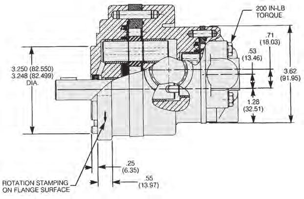
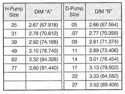
10 Dimensions Series D Dimensions 2-Bolt Mounting Clockwise rotation and A shaft shown (Port locations reverse for CCW rotation) Dimensions: Inches (mm) Side View Front View Rear View 10


11 Dimensions Series D Dimensions 4-Bolt Mounting Clockwise rotation and A shaft shown (Port locations reverse for CCW rotation.) Dimensions: Inches (mm) Side View Front View Rear View S Tang-end Shaft Option For Use With 4-Bolt Mounting Primarily used to direct-couple to electric motor drive. 11


 Dimensions: Inches (mm) Front View Side")
12 Dimensions Series D Dimensions 2-Bolt Mounting (With L Back Cover For Tank Mounting) Clockwise rotation and A shaft shown (Pump mounting flange opposite side of back cover centerline for CW rotation.) Dimensions: Inches (mm) Front View Side View Rear View 12


 Side View Dimensions: Inches")

13 Dimensions Series D Dimensions 4-Bolt Mounting (With L Back Cover For Tank Mounting) Clockwise rotation and A shaft shown (Pump mounting flange opposite side of back cover centerline for CW rotation.) Side View Dimensions: Inches (mm) Front View Rear View R Tang-end Shaft Option Primarily used to direct-couple to electric motor drives. 13

 Note: Kit")
 0-rings, (1) plug.")

 2-Quart Capacity Tank - Kit No.")
 inches 4-Quart Capacity Tank - Kit No.")
 inches 6-Quart Capacity Tank - Kit No.")
 inches Note: Kit includes- (1) reservoir")
14 Accessories Series D Dimensions Accessories For L Back Cover Pump Sub-plate for supply, return and gage ports Kit no K Dimensions: Inches (mm) Note: Kit includes (1) sub-plate, (4) mounting bolts, (3) 0-rings, (1) plug. Sub-Plate For Mounting (NFPA D01) Directional Control Valve Kit No K Note: Kit includes (1) sub-plate, (4) mounting bolts, (3) 0-rings, (1) plug. Tanks (Hydraulic Reservoir) 2-Quart Capacity Tank - Kit No B Dimension 4.67 (118.62) inches 4-Quart Capacity Tank - Kit No B Dimension (258.32) inches 6-Quart Capacity Tank - Kit No B Dimension (359.92) inches Note: Kit includes- (1) reservoir assembly, (1) suction strainer, (1) filler cap. 14
15 Ordering Information Series H Series H Standard Pumps 15
16 Ordering Information Series H Series H Standard Pumps 16

17 Technical Information Series H Performance Data Series H Fixed Displacement, Pressure-Loaded Gear Pump Features Pressure-loaded design Efficient, simple design - few moving parts Exceptionally compact and lightweight for their capacity Efficient at high-pressure operation Resistant to cavitation effects High tolerance to system contamination Reliable under cold weather operation Sleeve-bearing construction Multi-fluid compatibility Controls Optional built-in relief valve Optional built-in relief valve and flow divider Special controls (Consult Technical Services) Specifications Flow Ratings: 2.5 GPM (9.5 LPM) to 9.3 GPM (35.2 LPM) (At 1000 RPM) See next page for additional flow data Pressure Ratings: H25 thru H PSI (172 Bar) continuous H PSI (138 Bar) continuous H PSI (103 Bar) continuous Speed Ratings: H25 thru H to 4000 RPM H62, H77, H RPM Mounting: SAE-A - 2-Bolt Flange Optional SAE-A - 2-Bolt Flange Extended Front Cover Schematic Symbol (Basic Pump) Installation Data Inlet Conditions: 10 in. hg. max. vacuum condition (at 1800 RPM) 5 in. hg. max. vacuum condition (at max. RPM) 20 PSI (1.4 Bar) max. positive pressure Operating Temperature Range: -40 F to 185 F (-40 C to 85 C) Filtration: Maintain SAE Class 4 Installation Note: See page 28 for specific recommendations pertaining to system cleanliness, fluids, start-up, inlet conditions, shaft alignment, and other important factors relative to the proper installation and use of these pumps. Housing Material: Die-Cast Aluminum 17

18 Technical Information Series H Performance Data 18

 (100 SSU)")


19 Technical Information Series H Performance Data Based On Oil Temperature of 120 F (49 C) (100 SSU) Atmospheric Inlet H25/H31 Horsepower/Speed H25/H31 Flow/Speed H39/H49 Horsepower/Speed H39/H49 Flow/Speed 19


20 Technical Information Series H Performance Data Based On Oil Temperature of 120 F (49 C) (100 SSU) Atmospheric Inlet H62/H77 Horsepower/Speed H62/H77 Flow/Speed H90 Horsepower/Speed H90 Flow/Speed 20


 Series H Dimensions:")

21 Dimensions Dimensions 2-Bolt Mounting Clockwise rotation and A shaft shown (Port locations reverse for CCW rotation.) Series H Dimensions: Inches (mm) Side View Front View Rear View Cover Option A COVER 21

 Dimensions: Inches (mm) Side View Front View Rear View Circuit Variations")

22 Dimensions Series H Dimensions 2-Bolt Mounting Series with built-in relief valve and flow divider Clockwise rotation and A shaft shown (Port locations reverse for CCW rotation.) Dimensions: Inches (mm) Side View Front View Rear View Circuit Variations *NOTE: D Circuit: Relief valve flow and flow divider secondary flow return to pump inlet internally - primarily used in on-road equipment power steering. Relief drain port for B variation 9/16-18 UNF-2B SAE Straight Thread. 22


23 Dimensions Series H Dimensions Drive Shaft Configurations Dimensions: Inches (mm) T Shaft 3/4 Dia. 11 tooth spline Flat root side fit Diametral pitch 16/32 Pressure angle 30 No. of teeth 11 B Shaft 5/8 dia. 9-tooth spline Flat root side fit Diametral pitch 16/32 Pressure angle 30 No. of teeth 9 23
24 Ordering Information Series HD NOTE: For additional features or options, please consult the factory. Buna-N Seal Kit: K Buna-N Seal Kit with Plates: K Viton Seal Kit with Plates: K 24

 Pressure Ratings: See appropriate specification chart. Speed Ratings: Minimum: 500 RPM Maximum: Maximum rated speed of the larger displacement of the two pumps.")
25 Technical Information Series HD Performance Data Series HD Fixed Displacement, Tandem Pump Features Integral pressure-loaded pump design Individual inlet & outlet ports for 1st & 2nd stages of pump Fluids common/intermix between 1st & 2nd stages of pump. H series front cover mount - SAE A 2-Bolt Efficient at high-pressure operation Optional built-in relief - 2nd stage pump Specifications Flow Ratings: See appropriate specification chart. Schematic Symbol (Basic Pump) Pressure Ratings: See appropriate specification chart. Speed Ratings: Minimum: 500 RPM Maximum: Maximum rated speed of the larger displacement of the two pumps. See appropriate specification chart for this data. Torque: Combined: 800 in. lb. maximum total continuous duty 950 in. lb. maximum total intermittent duty 2nd Stage pump cannot exceed 260 in. lb. For additional information, see the Performance Data chart on page 26. Housing Material: Die-cast aluminum Installation Data Inlet Conditions: 10 in. hg. max. vacuum condition (At 1200 RPM) 5 in. hg. max. vacuum condition (At 3000 RPM) 20 PSI (1.4 Bar) max. positive pressure Operating Temperature Range: -40 F to 185 F (-40 C to 85 C) Filtration: Maintain SAE Class 4 Installation Note: See page 28 for specific recommendations pertaining to system cleanliness, fluids, start-up, inlet conditions, shaft alignment, and other important factors relative to the proper installation and use of these pumps. 25

26 Technical Information Series HD Performance Data Combined First and Second stage torque cannot exceed: 800 in. lb. Total continuous duty 950 in. lb. Total intermittent duty Second stage torque cannot exceed 260 in. lb. Example: 2500 PSI = 190 in. lb. x 2.5/1000 PSI = 475 in. lb. torque 2500 PSI = 81 in. lb. x 2.5/1000 PSI = 203 in. lb. torque 678 in. lb. total torque 26


27 Technical Information Series HD Performance Data Dimensions: Inches (mm) Front View Side View Rear View Rear (CCW) View Side View 27
28 Fluid Recommendations Series D/H/HD Fluid Recommendations Use premium-quality hydraulic fluid with operating viscosity range of SSU. The maximum start-up viscosity is 4000 SSU. The fluid should have maximum anti-wear properties, rust and oxidation treatment. Filtration For maximum pump and system component life, the system should be protected from contamination at a level not to exceed 125 particles greater than 10 microns per milliliter of fluid (SAE Class 4). Fluid Compatibility Petroleum-based fluid Water glycols Water emulsions Transmission fluid Mineral oil fluid NOTE: All data in this catalog are based on petroleum-based fluid. Pump pressure reduced by 1/2 of specified rating; pump speed rating, reduced by 1000 RPM from specified rating and DU bushings must be used when pump operates on water glycols and water emulsions. Consult the factory for special fluids. Installation And Mounting The mounting position is not restricted. Special Installations Consult your Parker representative for any application requiring the following: Pressure above rated Drive speed above maximum Indirect drive Fluids other than those specified Fluid temperature above 185 F. (85 C.). Start-Up On any start-up, where the pump suction line is empty of fluid, the circuit should be open to permit priming. Inlet Conditions Conditioning should not exceed 10 in. Hg. at 1800 RPM or 5 in. Hg. at pump maximum rated RPM. Inlet positive pressure should not exceed 20 PSI (1.4 Bar) maximum. Shaft Rotation And Line Up Pump and motor shaft alignment must be within.007 inches total indicator reading. Please follow the coupling manufacturer s recommended installation instructions to prevent end thrust on the pump shaft. Turn the pump by hand to assure freedom of rotation. The pump and motor must be on a rigid base. The coupling should be sized to absorb the peak horsepower generated. 28

29 Installation Information Series D/H/HD Instructions for Reversing Gear Pump Rotation The basic tools needed are a vise, preferably with soft jaws, a torque wrench, a thin screwdriver, a small hone stone, a ratchet and a paper clip. The D series will require a 1-1/2 socket; the H series an additional 1/4 hex head driver. It is also recommended that you have extra heat shields and gaskets on hand. Part numbers are and for the HD series; and for H series. To change rotation, hold the pump by the rear cover with the drive shaft pointing up. Remove all the bolts. The HD series will have four hex heads, and the H series will have six hex and two alien heads. For future reference, it would be helpful to scribe a line down the outlet side of the pump. If you choose not to mark it, the outlet port is usually the smallest. If the pump has a key-type shaft, remove the key and hone down any burrs that may be on the shaft. This is important as the next step will be to lift off the front cover, and any sharp edges could possibly damage the front seal or bearing. After the front cover is off, note the position of the little vent hole in the bronze wear plate, which should have come off with the front cover. The parts underneath also have a similar vent hole. Remove in order, the wear plate, the heat shield, the gasket, and the V-seal. To facilitate this, make a small hook with a paper clip and lift the part high enough to slip a screwdriver under it and carefully pry up. Please note that the heat shield, in particular, is very brittle and may crack if bent. After removing these four parts, reinstall the V-seal with the lips down in the front cover so that the vent hole is on the opposite side across from the reference mark. Use the screwdriver to seat it completely. Next, install the gasket, heat shield, and wear plate; again with the vent hole in line with that of the V-seal. The wear plate should be almost flush with the surface of the front cover. Remove the center section and note the notch cut on the inside. This will be installed in line and next to the vent hole in the wear plate. The dowel pins used to locate the center section may be removed temporarily to facilitate sliding the center section over the gear assemblies. Be careful not to pinch the O-ring between the front cover and center section. If it doesn t want to stay in place, it can be glued using heavy grease. 1. Shaft Seal 2. Cap Screws 3. Hex Screws 4. Washers 5. Front Cover 6. V-Seal 7. Dowel Pins 8. Gasket 9. Heat Shield 10. Wear Plate Rings 12. Center Section 13. Drive Gear Assembly 14. Driven Gear Assembly 15. Flow Control ( H Flow Divider Pump only) 16. Relief Valve ( H Flow Divider Pump Only) 17. Back Cover 18. Thrust Plate (H only) 19. Key (Where Required) into the center section, orienting the side with the bar in line with the vent hole, ensuring that the bronze side faces the gears. The rear cover is installed with the outlet side in line with the vent hole. The outlet side will be marked or can be identified by the smaller, internal cavity. As when installing the center section, be careful not to pinch the O-ring seal. The line that was originally scribed on the side should now be located at 180 on both the rear cover and center section from that on the front cover. Install the bolts and tighten down by hand. Then, torque to the proper setting, alternating from side to side. The correct torque specifications are lbs. for the D and H series. Reverse or remove the rotation arrow originally stamped on the mounting flange. Testing Procedure After the pump has been reinstalled, run for 2-3 minutes before pressurizing. Try to apply pressure gradually for an additional five minutes, but do not pressurize for longer than 5 seconds at a time. If the pump is an H series, install the thrust plate 29
30 Offer of Sale Series D/H/HD The items described in this document and other documents or descriptions provided by, its subsidiaries and its authorized distributors are hereby offered for sale at prices to be established by, its subsidiaries and its authorized distributors. This offer and its acceptance by any customer ( Buyer ) shall be governed by all of the following Terms and Conditions. Buyer s order for any such items, when communicated to, its subsidiary or an authorized distributor ( Seller ) verbally or in writing, shall constitute acceptance of this offer. 1. Terms and Conditions of Sale: All descriptions, quotations, proposals, offers, acknowledgments, acceptances and sales of Seller s products are subject to and shall be governed exclusively by the terms and conditions stated herein. Buyer s acceptance of any offer to sell is limited to these terms and conditions. Any terms or conditions in addition to, or inconsistent with those stated herein, proposed by Buyer in any acceptance of an offer by Seller, are hereby objected to. No such additional, different or inconsistent terms and conditions shall become part of the contract between Buyer and Seller unless expressly accepted in writing by Seller. Seller s acceptance of any offer to purchase by Buyer is expressly conditional upon Buyer s assent to all the terms and conditions stated herein, including any terms in addition to, or inconsistent with those contained in Buyer s offer, Acceptance of Seller s products shall in all events constitute such assent. 2. Payment: Payment shall be made by Buyer net 30 days from the date of delivery of the items purchased hereunder. Amounts not timely paid shall bear interest at the maximum rate permitted by law for each month or portion thereof that the Buyer is late in making payment. Any claims by Buyer for omissions or shortages in a shipment shall be waived unless Seller receives notice thereof within 30 days after Buyer s receipt of the shipment. 3. Delivery: Unless otherwise provided on the face hereof, delivery shall be made F.O.B. Seller s plant. Regardless of the method of delivery, however, risk of loss shall pass to Buyer upon Seller s delivery to a carrier. Any delivery dates shown are approximate only and Seller shall have no liability for any delays in delivery. 4. Warranty: Seller warrants that the items sold hereunder shall be free from defects in material or workmanship for a period of 18 months from date of shipment from. THIS WARRANTY COM- PRISES THE SOLE AND ENTIRE WARRANTY PERTAINING TO ITEMS PROVIDED HEREUNDER. SELLER MAKES NO OTHER WARRANTY, GUARANTEE, OR REPRESENTATION OF ANY KIND WHATSOEVER. ALL OTHER WARRANTIES, INCLUDING BUT NOT LIMITED TO, MER- CHANTABILITY AND FITNESS FOR PURPOSE, WHETHER EXPRESS, IMPLIED, OR ARISING BY OPERATION OF LAW, TRADE USAGE, OR COURSE OF DEALING ARE HEREBY DISCLAIMED. NOTWITHSTANDING THE FOREGOING, THERE ARE NO WARRAN- TIES WHATSOEVER ON ITEMS BUILT OR ACQUIRED WHOLLY OR PARTIALLY, TO BUYER S DESIGNS OR SPECIFICATIONS. 5. Limitation Of Remedy: SELLER S LIABILITY ARISING FROM OR IN ANY WAY CONNECTED WITH THE ITEMS SOLD OR THIS CONTRACT SHALL BE LIMITED EXCLUSIVELY TO REPAIR OR REPLACEMENT OF THE ITEMS SOLD OR REFUND OF THE PURCHASE PRICE PAID BY BUYER, AT SELLER S SOLE OPTION. IN NO EVENT SHALL SELLER BE LIABLE FOR ANY INCIDENTAL, CONSEQUENTIAL OR SPECIAL DAMAGES OF ANY KIND OR NATURE WHATSOEVER, INC. LUDING BUT NOT LIMITED TO LOST PROFITS ARISING FROM OR IN ANY WAY CONNECTED WITH THIS AGREEMENT OR ITEMS SOLD HEREUNDER, WHETHER ALLEGED TO ARISE FROM BREACH OF CONTRACT, EXPRESS OR IMPLIED WARRANTY, OR IN TORT, IN- CLUDING WITHOUT LIMITATION, NEGLIGENCE, FAILURE TO WARN OR STRICT LIABILITY. 6. Changes, Reschedules and Cancellations: Buyer may request to modify the designs or specifications for the items sold hereunder as well as the quantities and delivery dates thereof, or may request to cancel all or part of this order, however, no such requested modification or cancellation shall become part of the contract between Buyer and Seller unless accepted by Seller in a written amendment to this Agreement. Acceptance of any such requested modification or cancellation shall be at Seller s discretion, and shall be upon such terms and conditions as Seller may require. 7. Special Tooling: A tooling charge may be imposed for any special tooling, including without limitation, dies, fixtures, molds and patterns, acquired to manufacture items sold pursuant to this contract. Such special tooling shall be and remain Seller s property notwithstanding payment of any charges by Buyer. In no event will Buyer acquire any interest in apparatus belonging to Seller which is utilized in the notwithstanding any charges paid by Buyer. Unless otherwise agreed, Seller shall have the right to alter, discard or otherwise dispose of any special tooling or other property in its sole discretion at any time. 8. Buyer s Property: Any designs, tools, patterns, materials, drawings, confidential information or equipment furnished by Buyer or any other items which become Buyer s property, may be considered obsolete and may be destroyed by Seller after two (2) consecutive years have elapsed without Buyer placing an order for the items which are manufactured using such property, Seller shall not be responsible for any loss or damage to such property while it is in Seller s possession or control. 9. Taxes: Unless otherwise indicated on the face hereof, all prices and charges are exclusive of excise, sales, use, property, occupational or like taxes which may be imposed by any taxing authority upon the manufacture, sale or delivery of the items sold hereunder. If any such taxes must be paid by Seller or if Seller is liable for the collection of such tax, the amount thereof shall be in addition to the amounts for the items sold. Buyer agrees to pay all such taxes or to reimburse Seller therefore upon receipt of its invoice. If Buyer claims exemption from any sales, use or other tax imposed by any taxing authority, Buyer shall save Seller harmless from and against any such tax, together with any interest or penalties thereon which may be assessed if the items are held to be taxable. 10. Indemnity For Infringement of Intellectual Property Rights: Seller shall have no liability for infringement of any patents, trademarks, copyrights, trade dress, trade secrets or similar rights except as provided in this Part 10. Seller will defend and indemnify Buyer against allegations of infringement of U.S. Patents, U.S. Trademarks, copyrights, trade dress and trade secrets (hereinafter Intellectual Property Rights ). Seller will defend at its expense and will pay the cost of any settlement or damages awarded in an action brought against Buyer based on an allegation that an item sold pursuant to this contract infringes the Intellectual Property Rights of a third party. Seller s obligation to defend and indemnify Buyer is contingent on Buyer notifying Seller within ten (10) days after Buyer becomes aware of such allegations of infringement, and Seller having sole control over the defense of any allegations or actions including all negotiations for settlement or compromise. If an item sold hereunder is subject to a claim that it infringes the Intellectual Property Rights of a third party, Seller may, at its sole expense and option, procure for Buyer the right to continue using said item, replace or modify said item so as to make it noninfringing, or offer to accept return of said item and return the purchase price less a reasonable allowance for depreciation. Notwithstanding the foregoing, Seller shall have no liability for claims of infringement based on information provided by Buyer, or directed to items delivered hereunder for which the designs are specified in whole or part by Buyer, or infringements resulting from the modification, combination or use in a system of any item sold hereunder. The foregoing provisions of this Part 10 shall constitute Seller s sole and exclusive liability and Buyer s sole and exclusive remedy for infringement of Intellectual Property Rights. If a claim is based on information provided by Buyer or if the design for an item delivered hereunder is specified in whole or in part by Buyer, Buyer shall defend and indemnify Seller for all costs, expenses or judgments resulting from any claim that such item infringes any patent, trademark, copyright, trade dress, trade secret or any similar right. 11. Force Majeure: Seller does not assume the risk of and shall not be liable for delay or failure to perform any of Seller s obligations by reason of circumstances beyond the reasonable control of Seller (hereinafter Events of Force Majeure ). Events of Force Majeure shall include without limitation, accidents, acts of God, strikes or labor disputes, acts, laws, rules or regulations of any government or government agency, fires, floods, delays or failures in delivery of carriers or suppliers, shortages of materials and any other cause beyond Seller s control. 12. Entire Agreement/Governing Law: The terms and conditions set forth herein, together with any amendments, modifications and any different terms or conditions expressly accepted by Seller in writing, shall constitute the entire Agreement concerning the items sold, and there are no oral or other representations or agreements which pertain thereto. This Agreement shall be governed in all respects by the law of the State of Ohio. No actions arising out of the sale of the items sold hereunder or this Agreement may be brought by either party more than two (2) years after the cause of action accrues. 9/91-P 30


31 6035 Parkland Blvd. Cleveland, Ohio, US Tel: (216) Fax: (216) About Parker Hannifin is a leading global motion-control company dedicated to delivering premier customer service. A Fortune 500 corporation listed on the New York Stock Exchange (PH), our components and systems comprise over 1,400 product lines that control motion in some 1,000 industrial and aerospace markets. Parker is the only manufacturer to offer its customers a choice of hydraulic, pneumatic, and electro mechan ical motion-control solutions. Our Company has the largest distribution network in its field, with over 7,500 distributors serving nearly 400,000 customers worldwide. Parker s Charter To be a leading worldwide manufacturer of components and systems for the builders and users of durable goods. More specifically, we will design, market and manufacture products controlling motion, flow and pressure. We will achieve profitable growth through premier customer service. Product Information North American customers seeking product infor mation, the location of a nearby distributor, or repair services will receive prompt attention by calling the Parker Product Information Center at our toll-free number: C-PARKER ( ). In Europe, call C-PARKER-H ( ). The Aerospace Group is a leader in the development, design, manufacture and servicing of control systems and components for aerospace and related high- technology markets, while achieving growth through premier customer service. The Climate & Industrial Controls Group designs, manufactures and markets system-control and fluidhandling components and systems to refrigeration, air-conditioning and industrial customers worldwide. The Fluid Connectors Group designs, manu factures and markets rigid and flexible connectors, and associated products used in pneumatic and fluid systems. The Seal Group designs, manufactures and distributes industrial and commercial sealing devices and related products by providing superior quality and total customer satisfaction. The Hydraulics Group designs, produces and markets a full spectrum of hydraulic com ponents and systems to builders and users of industrial and mobile machinery and equipment. The Filtration Group designs, manufactures and markets quality filtration and clarification products, providing customers with the best value, quality, technical support, and global availability. The Automation Group is a leading supplier of pneumatic and electro - mechanical components and systems to automation customers worldwide. The Instrumentation Group is a global leader in the design, manufacture and distribution of highquality critical flow components for worldwide process instrumentation, ultra-high-purity, medical and analytical applications.

32 Your complete source for quality tube fittings, hose & hose fittings, brass & composite fittings, quickdisconnect couplings, valves and assembly tools, locally available from a worldwide network of authorized distributors. Fittings: Available in inch and metric sizes covering SAE, BSP, DIN, GAZ, JIS and ISO thread configurations, manufactured from steel, stainless steel, brass, aluminum, nylon and thermoplastic. Hose, Tubing and Bundles: Available in a wide variety of sizes and materials including rubber, wire-reinforced, thermoplastic, hybrid and custom compounds. Worldwide Availability: Parker operates Fluid Connectors manufacturing locations and sales offices throughout North America, South America, Europe and Asia-Pacific. For information, call toll free... For C-PARKER information, call For ( ) information, call The Hope Group Branch Locations Branch Locations Massachusetts Maine North American Divisions Fitchburg Parker Energy Products Division Bangor Store Stafford, TX 58 phone Parker Crawford StoreStreet Tel: fax Perry 281 Road Fax: Tel: Fluid Fax: System Connectors Northborough Division Corporate Otsego, MI LewistonHeadquarters phone fax Parker Bearfoot StoreRoad Tel: Enterprise Street Fax: Hose Tel: Products Division Wickliffe, Fax: OH Weymouth phone Parker fax South Store Portland 50 Industrial Parker Finnell Store Drive, Unit Hose Division Tel: Wickliffe, 5 Wallace OH Avenue Fax: phone Tel: fax Fax: Rhode Island Parflex Division Ravenna, OH phone New Hampshire Cranston fax Parker Manchester Store 215 Quick Parker Niantic Store Coupling Avenue Division Tel: Minneapolis, Candia Road MN Fax: phone Tel: fax Fax: Tube Fittings Division Connecticut Columbus, OH phone N fax orth Haven The Hope Group - No. Haven 350 Sackett Point Road Tel: Fax: Maine Massachusetts Distribution Service Centers Bangor Buena Park, CA Fitchburg Parker Store phone fax Parker 257 Perry Store Road Tel: Crawford Street Conyers, Tel: Fax: GA phone Fax: fax Lewiston Northborough Parker Store Louisville, KY phone Corporate 14 Enterprise 502 Headquarters Street fax 70 Tel: Bearfoot Road 4180 Tel: Fax: Portland, Fax: OR phone South 503 Portland fax Weymouth Parker Store Toledo, Parker 5 Wallace Store Avenue OH phone 50 Tel: Finnell Drive, Unit fax Tel: Fax: fax Fax: (FCG Kit Operations) New Hampshire Canada Grimsby, Rhode ONT Island Manchester phone fax Cranston Parker Store (Contact Parker 880 Candia Store Grimsby Roadfor other Service 215 Tel: Niantic Center Avenue locations.) Tel: Fax: Fax: The Hope Group 70 Bearfoot Road Northborough, MA Phone: Fax: ISO 9001:2008 Certified ITAR Registered
Fixed Displacement Gear Pumps
 Fixed Displacement Gear Pumps D/H/HD Series Introduction Series D/H/HD Features Pressure-loaded design Efficient, simple design - few moving parts Exceptionally compact and lightweight for their capacity
Fixed Displacement Gear Pumps
 Fixed Displacement Gear Pumps D/H/HD Series Catalog HY09-D/H/HD/US Table of Contents Series D/H/HD Description Page No. Introduction... 3 General Description... 4 "D" Series Ordering Information.... 5
H1/H1A Series Variable Displacement, Closed Loop Piston Pump
 Hydraulics Variable Displacement, Closed Loop Piston Pump Catalog No. HY13-1591/US WARNING FAILURE OR IMPROPER SELECTION OR IMPROPER USE OF THE PRODUCTS AND/OR SYSTEMS DE- SCRIBED HEREIN OR RELATED ITEMS
Motorized Control Valves
 Motorized Control Valves Gland Connector Sold as Option. See page XX. Reference coil option chart for additional electrical coil offerings. AC control systems industrial boilers water and purification
Gerotor Pump & Motor zgp06
 zgp Aluminum High Speed, Low Torque Series Catalog HY9-PGG/MGG/US Catalog HY9-PGG/MGG/US General Information The Parker Hannifin Assures: Consistent quality Technical innovation Premier customer service
SNAPP. The One-Piece, High-Performance Snap-In Fuel Filter Water Separator
 SNAPP The One-Piece, High-Performance Snap-In Fuel Filter Water Separator Now, getting the fuel filtration you need is a SNAPP. SNAPP. The fuel filter change that changes everything. The world turns to
Parts List 885 Series
 Parts List Effective: October 15, 2001 Supersedes: P410-885 Dated September 2000 WARNING FAILURE OR IMPROPER SELECTION OR IMPROPER USE OF THE PRODUCTS AND/OR SYSTEMS DESCRIBED HEREIN OR RELATED ITEMS CAN
GreenMAX. Heavy-Duty, High-Capacity, Fuel Filter/Water Separator With Options for All-Weather Operations
 GreenMAX Heavy-Duty, High-Capacity, Fuel Filter/Water Separator With Options for All-Weather Operations The World's Most Innovative Diesel Fuel Filter Water Separator. Clean is the new green. GreenMAX
Maintenance Instruction & Parts List. ERV Series Value Line Rodless Linear Actuator. Bulletin PM-ERV-B/USA
 Bulletin PM-ERV-B/USA Maintenance Instruction & Parts List Revision Date: September 2005 Supersedes: April 2002 ERV Series Value Line Rodless Linear Actuator WARNING FAILURE OR IMPROPER SELECTION OR IMPROPER
PVD Series Power Valves Stand alone/stackable with modular solenoid pilot system
 PVD Series Power Valves Stand alone/stackable with modular solenoid pilot system PVD Series Power Valves General Description Telepneumatic offers the unique benefits of ceramic slide construction with
Diesel Fuel Cart. Portable Diesel Fuel Filtration Cart
 Portable Diesel Fuel Filtration Cart Filtering new fluid before putting into service Transferring fluid from drums or storage tanks to system reservoirs Conditioning bulk fluid in storage tanks Compliments
MINING FORESTRY MOBILE TRUCK AGRICULTURE MATERIAL HANDLING OPTIMUM
 MINING FORESTRY MOBILE TRUCK AGRICULTURE MATERIAL HANDLING OPTIMUM Muncie Power Products OPTIMUM Series gear pumps/motors offer premier performance for a wide variety of applications across several industries.
High Pressure Gear Pumps & Motors Series PZG Pumps Series MZG Motors
 High Pressure Gear Pumps & Motors Series PZG Pumps Series MZG Motors Bulletin 650-Z1 High Pressure Gear Pumps and Gear Motors for today s demanding mobile and industrial applications. The PZG and MZG Series
Parts List 236 Series
 Parts List Effective: January 15, 2009 Supersedes: HY25-2236-M1/US Dated July 2007 WARNING FAILURE OR IMPROPER SELECTION OR IMPROPER USE OF THE PRODUCTS AND/OR SYSTEMS DESCRIBED HEREIN OR RELATED ITEMS
Helical Hydraulic Rotary Actuators. Series L and T
 Helical Hydraulic Rotary Actuators Catalog HY341000 Operating Technology Industries Served: Agriculture Construction Energy Marine Material Handling Military Mining Truck/Trailer and many others Helac
Owner s Manual Power Take-Offs
 Power Take-Offs Effective: April 2007 Supersedes: HY25-1569-M1/US January 2007 CAT-D Series CAT-H Series WARNING FAILURE OR IMPROPER SELECTION OR IMPROPER USE OF THE PRODUCTS AND/OR SYSTEMS DESCRIBED HEREIN
Parts List 230/231 Series
 Parts List Effective: December 15, 2001 Supersedes: P410-230/231 Dated December 2000 WARNING FAILURE OR IMPROPER SELECTION OR IMPROPER USE OF THE PRODUCTS AND/OR SYSTEMS DESCRIBED HEREIN OR RELATED ITEMS
Hydraulic Pump Division. P1/PD Models 075, 100, and 140 open-circuit axial piston pumps 280 bar rated pressure Service information
 Hydraulic Pump Division P1/PD Models 075, 100, and 140 open-circuit axial piston pumps 280 bar rated pressure Service information Pub. LTE-00062-3-B Revised 6/05 Hydraulic Pump Division 14249 Industrial
Portable Filter Carts. Models 5MFP & 10MFP with Modufl ow and Intelli-Cart
 Models 5MFP & 10MFP with Modufl ow and Intelli-Cart 174 Applications Filtering new fluid before putting into service Transferring fluid from drums or storage tanks to system reservoirs Conditioning fluid
BC Brake Caliper. (i) MEX (55) QRO (442) MTY (81) DIST. AUTORIZADO
 MEX (55) QRO (442) MTY (81) DIST. AUTORIZADO") MEX (55) 5 6 QRO (44) 95 7 60 MTY () 54 0 BC Brake Caliper (i) FORM NO. L-0066-B-040 In accordance with Nexen s established policy of constant product improvement, the specifications contained in this
MEX (55) 5 6 QRO (44) 95 7 60 MTY () 54 0 BC Brake Caliper (i) FORM NO. L-0066-B-040 In accordance with Nexen s established policy of constant product improvement, the specifications contained in this
TRUCK PRODUCT LINE A DIVISION OF DAKOTA FLUID POWER, INC.
 TRUCK PRODUCT LINE 2210 Main Ave W, West Fargo, ND 58078 877.410.7072 www.epgdivision.com A DIVISION OF DAKOTA FLUID POWER, INC. ABOUT US About: Engineered Products Group (EPG), a division of Dakota Fluid
Elgin Hydraulic Clutch-Brake ECB-240, Product Number FORM NO. L F FORM NO. L F-0704
 Elgin Hydraulic Clutch-Brake ECB-20, Product Number 96225 FORM NO. L-20283-F-070 1 FORM NO. L-20283-F-070 In accordance with Nexen s established policy of constant product improvement, the specifications
Dual Fueler CP3 Pump Kit Installation Guide for LB7
 Pacific Performance Engineering, Inc. www.ppediesel.com Dual Fueler Installation Guide Dual Fueler CP3 Pump Kit Installation Guide for LB7 Supplied Parts: 1. Control Module Pulley 9. Oil Filler Tube 2.
F SERIES GEAR PUMP. 2 Muncie Power Products, Inc Muncie Power Products, Inc.
 ALL NEW DESIGN F SERIES GEAR PUMP ALL NEW DESIGN Ultimate power and performance in a small package best describes the all new F Series gear pumps. Designed exclusively for those low flow applications.
Super Charged Piston Pumps Variable Displacement For Open Circuits. PAVC Medium Pressure
 aerospace climate control electromechanical filtration fluid & gas handling hydraulics pneumatics process control sealing & shielding PAVC Medium Pressure Super Charged Piston Pumps Variable Displacement
Super Charged Piston Pumps Variable Displacement For Open Circuits. PAVC Medium Pressure
 aerospace climate control electromechanical filtration fluid & gas handling hydraulics pneumatics process control sealing & shielding PAVC Medium Pressure Super Charged Piston Pumps Variable Displacement
Five Hoses. Two Fittings. One Solution. GLOBALCORE The world s first high-performance, cohesive hose and fitting system.
 Five Hoses. Two Fittings. One Solution. GLOBALCORE The world s first high-performance, cohesive hose and fitting system. Five Hoses. Two Fittings. One Solution... Providing a simple solution of robust
BELLOWS VALVES. Microelectronics Product Line. Catalog 4506/USA October 2003
 BELLOWS VALVES Microelectronics Product Line Catalog 46/USA October 2003 BELLOWS VALVES Microelectronics Product Line Catalog 46/USA October 2003 table of contents Veriflo Division................... 1
Transair: Advanced Pipe Systems Pocket Installation Guide [1/2"] [1"] [1 1/2"] [2"] [2 1/2"] [3"] [4"] [6"]
![Transair: Advanced Pipe Systems Pocket Installation Guide [1/2] [1] [1 1/2] [2] [2 1/2] [3] [4] [6]](/thumbs/93/113010388.jpg "Transair: Advanced Pipe Systems Pocket Installation Guide [1/2] [1] [1 1/2] [2] [2 1/2] [3] [4] [6]") Transair: Advanced Pipe Systems Pocket Installation Guide [1/2"] [1"] [1 1/2"] [2"] [2 1/2"] [3"] [4"] [6"] Certifications and guarantees Offering a full range of diameters to fit your design needs. Transair
Transair: Advanced Pipe Systems Pocket Installation Guide [1/2"] [1"] [1 1/2"] [2"] [2 1/2"] [3"] [4"] [6"] Certifications and guarantees Offering a full range of diameters to fit your design needs. Transair
OPERATING INSTRUCTIONS AND PARTS LIST BRIDGE DRIVE GEAR CASE
 OPERATING INSTRUCTIONS AND PARTS LIST BRIDGE DRIVE GEAR CASE GENERAL Units are intended to be used within 30 days after receipt. If they are to be stored for a longer period of time, contact the factory
Pneumatic Actuator Products
 aerospace climate control electromechanical filtration fluid & gas handling hydraulics pneumatics process control sealing & shielding Cylinders, Guided Cylinders and Rotary Actuators Catalog 0900P-5 ENGINEERING
Dual Fueler CP3 Pump Kit Installation Guide for LBZ/LMM
 Dual Fueler CP3 Pump Kit Installation Guide for LBZ/LMM Supplied Parts: 19b 19c 19a 1. Control Module 2. 3/8 Inlet Fuel Line with Attached 1/2 x 1/2 x 3/8 T Connector 3. 5/16 Return Fuel Line with Attached
DAP-625S and DAP-875S
 AIR CHAMP PRODUCTS DAP-625S and DAP-875S (i) FORM NO. L-20078-B-0501 In accordance with Nexen s established policy of constant product improvement, the specifications contained in this manual are subject
FEATURES: APPLICATIONS:
 Ultimate power and performance in a small package best describes the all new F4 Series gear pumps. The pressure balanced bushing blocks and sleeve bearings provide both extra long life and high performance.
Features: Applications: 12 standard sizes Pressures to 3625 PSI (250 Bar)
") Ultimate power and performance in a small package best describes the all new F4 Series gear pumps. The pressure balanced bushing blocks and sleeve bearings provide both extra long life and high performance.
Ultimate power and performance in a small package best describes the all new F4 Series gear pumps. The pressure balanced bushing blocks and sleeve bearings provide both extra long life and high performance.
Parker Hydraulic Tube Bender, Model HB632
 May 2001 Parker Hydraulic Tube Bender, Model HB632 The Fitting Authority WARNING FAILURE OR IMPROPER SELECTION OR IMPROPER USE OF THE PRODUCTS AND/OR SYSTEMS DESCRIBED HEREIN OR RELATED ITEMS CAN CAUSE
3V SERIES SOLENOID VALVE
 3V110-410 SERIES SOLENOID VALVE Valve Model 3V110-1/8 3V210-1/4 3V310-3/8 3V410-1/2 Port & Mounting Action & Motion Operating Pressure Body Ported Air Pilot, Spool Design, Response Time
P1 Series Axial Piston Pumps Variable Displacement. Catalog HY /NA,EU
 P1 Series Axial Piston Pumps Variable Displacement Catalog HY28-2664/NA,EU HINWEIS WARNING FAILURE OR IMPROPER SELECTION OR IMPROPER USE OF THE PRODUCTS AND/OR SYSTEMS DESCRIBED HEREIN OR RELATED ITEMS
STC 2W Series Solenoid Valves
 STC 2W160-500 Series Solenoid Valves 2W160-500 Series Solenoid Valve Specifications Valve Model 2W160-3/8 2W160-1/2 2W200-3/4 2W250-1 2W350-1 1/4 2W400-1 1/2 2W500-2 Valve Type Action 2 Way, Normally Closed
HR-20P Pneumatically Controlled Pressure Regulator
 HR-20P Pneumatically Controlled Pressure Regulator Instruction and Service Manual Hydroplex Corporation 230 West Gloria Switch Rd. Lafayette, LA 70507 337-233-0626 www.hydroplexpumps.com I. General Instructions
Parts List 880 Series
 Parts List Effective: August 15, 2006 Supersedes: HY25-2880-M1/US Dated Feb. 15, 2005 WARNING FAILURE OR IMPROPER SELECTION OR IMPROPER USE OF THE PRODUCTS AND/OR SYSTEMS DESCRIBED HEREIN OR RELATED ITEMS
AIR CHAMP PRODUCTS. User Manual. DAP-625S and DAP-875S FORM NO. L D-0914
 AIR CHAMP PRODUCTS User Manual DAP-65S and DAP-875S FORM NO. L-0078-D-09 In accordance with Nexen s established policy of constant product improvement, the specifications contained in this manual are subject
DODGE CUMMINS MK-2 Micro-Kleen System
 Installation Manual P/N MK20306 2003-07 DODGE CUMMINS MK-2 Micro-Kleen System Installation Instructions P/N MK20306 2 Micron Fuel Filter Installation PLEASE READ ALL INSTRUCTIONS BEFORE BEGINNING INSTALLATION
AIR CHAMP PRODUCTS. User Manual. Sheave & Pilot Mount Clutch-Brake Model BCB-275 FORM NO. L F-0414 FORM NO. L F-0414
 AIR CHAMP PRODUCTS User Manual Sheave & Pilot Mount Clutch-Brake Model BCB-275 i In accordance with Nexen s established policy of constant product improvement, the specifications contained in this manual
RACE PPE Manifolds and Up-Pipes
 RACE ONLY High-Flow Exhaust Manifolds with Up-pipes GM DURAMAX 6.6L 2001-2015 DISCLAIMER OF LIABILITY This is a performance product which increases horsepower above factory specifications. Additional horsepower
Guardian Steel Gear Shaft Coupling
 Guardian Steel Gear Shaft Coupling P-8609-GC GUA-MRK-DOC-026 Service & Installation Instructions TABLE OF CONTENTS NOTICES AND WARNINGS PAGE 2 SECTION 1 COUPLING OVERVIEW PAGE 3 SECTION 2 TOOLS/MATERIALS
STC 2DS Series Anti-Hammering Slow Closing Pilot Solenoid Valves
 STC 2DS500-2000 Series Anti-Hammering Slow Closing Pilot Solenoid Valves 2DS500-2000 Series Solenoid Valve Specifications Valve Model 2DS400F 2DS500F 2DS650F 2DS800F 2DS1000F 2DS1250F 2DS1500F 2DS2000F
DODGE CUMMINS Arctic-Heat Grid Relocation Kit
 Installation Manual P/N 07509-350-GRK 2007.5-09 DODGE CUMMINS Arctic-Heat Grid Relocation Kit Installation Instructions P/N 07509-350-GRK GDP Arctic-Heat Grid Heater Installation PLEASE READ ALL INSTRUCTIONS
Single-Position Detent Clutch DC Series. (i) MTY (81) MEX (55) QRO (442)
 MTY (81) MEX (55) QRO (442)") Single-Position Detent Clutch DC Series (i) FORM NO. L-2017-A-001 In accordance with Nexen s established policy of constant product improvement, the specifications contained in this manual are subject
Single-Position Detent Clutch DC Series (i) FORM NO. L-2017-A-001 In accordance with Nexen s established policy of constant product improvement, the specifications contained in this manual are subject
Stainless Steel Pilot Piston Solenoid Valve 2MS Series for High Temperature & High Pressure
 Stainless Steel Pilot Piston Solenoid Valve 2MS Series for High Temperature & High Pressure S T C TM To Order, Please Specify: 1) Model No., 2) Voltage 2 Way, NC Pilot Piston Stainless Steel Part No. Voltage
4V130P-430P SERIES AIR PILOT VALVE
 4V130P-430P SERIES AIR PILOT VALVE Valve Model 4V130P-1/8 4V230P-1/4 4V330P-3/8 4V430P-1/2 Port & Mounting Action & Motion Operating Pressure Body Ported Double Solenoid, Spool Design, 3 Position, Pressure
STC E-Series Electrically Actuated Ball Valves 316 Stainless Steel, 2-Way or 3-Way
 STC E-Series Electrically Actuated Ball Valves 316 Stainless Steel, 2-Way or 3-Way Ordering Part No. = (e.g., E 1/2-3-S) Indicator / Control E 1/2 - - - 3-S Model Name Electric Actuated Valves E Port Size
Defrost Differential Pressure Regulating Valves Installation and Service Instructions
 July 202 / Bulletin 90-5 Defrost Differential Pressure Regulating s Installation and Service Instructions (O)LDR-6, (O)LDR-20, DDR-20 Obsolete: (O)LDR-5, XTM-, XTM-5, XTO-, -4 (Included for part s breakdown)
Stage4 Installation Guide STAGE 4 TRANSMISSION KIT INSTALLATION GUIDE Allison LB7/ LLY only for 5 speed trasmissions
 STAGE 4 TRANSMISSION KIT INSTALLATION GUIDE 2001-2005 Allison LB7/ LLY only for 5 speed trasmissions DISCLAIMER OF LIABILITY This is a performance product which can be used with increased horsepower above
BC Brake Caliper 1 FORM NO. L D-0414
 BC Brake Caliper FORM NO. L-0066-D-044 In accordance with Nexen s established policy of constant product improvement, the specifications contained in this manual are subject to change without notice. Technical
NECO Pumping Systems
 INSTALLATION OPERATION & MAINTENANCE INSTRUCTIONS For Your NECO Pumping Systems Fuel Oil Transfer System THIS COMPLETELY ASSEMBLED, TESTED, PACKAGED SYSTEM IS OF THE HIGHEST QUALITY AND DESIGN. TO OBTAIN
HD Series Linear Positioners. Catalog 8093/USA zt12. Daedal
 HD Series Linear Positioners Catalog 8093/USA zt12 Daedal HD Series Linear Positioners HD Series Linear Positioners Pre-engineered package Performance matched components Protection from environment Robust
L DODGE CUMMINS MK-2 + BLK APPS Mount
 Installation Manual P/N MK20305-APPS 2003-05 5.9L DODGE CUMMINS MK-2 + BLK APPS Mount Installation Instructions P/N MK20305-APPS 2 Micron + Big Line Kit APPS Mount Installation PLEASE READ ALL INSTRUCTIONS
AIR CHAMP PRODUCTS. User Manual. BW Clutch or Brake Sheave, Pilot and Coupling Mount FORM NO. L U-1209 FORM NO.
 AIR CHAMP PRODUCTS User Manual BW Clutch or Brake Sheave, Pilot and Coupling Mount i In accordance with Nexen s established policy of constant product improvement, the specifi cations contained in this
STC 2L Series Solenoid Valves
 STC 2L170-500 Series Solenoid Valves 2L170-500 Series Solenoid Valve Specifications Valve Model 2L170-3/8 2L170-1/2 2L170-3/4 2L200-1 2L300-1 1/2 2L500-2 Valve Type Action 2 Way, Normally Closed (NC) Pilot
Single Post Caliper Brake VC500
 Single Post Caliper Brake VC500 1 In accordance with Nexen s established policy of constant product improvement, the specifications contained in this manual are subject to change without notice. Technical
POWER END PARTS LIST
 GARDNER DENVER 302WPD997 Rev B April 2008 WELL SERVICING PUMP MODEL GD-600 POWER END PARTS LIST ECN 1040704 GD-600 WELL SERVICING PUMP MAINTAIN PUMP RELIABILITY AND PERFORMANCE WITH GENUINE GARDNER DENVER
7.3L POWERSTROKE BANJO BOLT KIT Fits L Powerstroke Diesel. Installation Guide
 7.3L POWERSTROKE BANJO BOLT KIT Fits 94-03 7.3L Powerstroke Diesel Installation Guide INSPECT CONTENTS OF THIS KIT THOROUGHLY BEFORE STARTING THE INSTALLATION PROCESS! IF YOU FIND A PROBLEM WITH YOUR PACKAGE:
TECHNICAL SERVICE MANUAL
 Electronic copies of the most current TSM issue can be found on the Viking Pump website at www.vikingpump.com TECHNICAL SERVICE MANUAL industrial heavy duty motor speed pumps SERIES 4076 AND 4176 SIZES
½ DODGE CUMMINS OEM BYPASS LIFT PUMP KIT Installation Instructions Part #
 29 July 2005 2003-04.5 Dodge Cummins OEM Bypass Lift Pump Kit # 1050227-1 - 2003-04½ DODGE CUMMINS OEM BYPASS LIFT PUMP KIT Installation Instructions Part # 1050227 PLEASE READ ALL INSTRUCTIONS CAREFULLY
Female Plug. connecting to Fuel Quantity
 **Ag Diesel Solutions recommends replacing the Transorb/Suppressor Diode before the installation of this module*** Red wire = 12V Constant power. Male Plug connecting to Fuel Quantity Valve Black wire
Users Guide for Ac-sync
 Problem solved. Users Guide for Ac-sync Thank you for choosing Anywhere Cart! The AC-SYNC is designed to sync, charge and store 1-36 ipads or tablets. Adjustable device divider bays allow fitment of any
FCB-450, LCB-600, MCB-800
 AIR CHAMP PRODUCTS User Manual FCB-450, LCB-600, MCB-800 Clutch-Brakes (i) In accordance with Nexen s established policy of constant product improvement, the specifications contained in this manual are
INSTALLATION INSTRUCTION & OWNER S MANUAL
 CS-2500 & CS-2500P Water Filtration System INSTALLATION INSTRUCTION & OWNER S MANUAL Ver 1.2 All Rights Reserved APEC Water Systems Please keep this Owner s Manual for future reference. It contains useful
CONTENTS. VIKING PUMP, INC. A Unit of IDEX Corporation Cedar Falls, IA USA SECTION TSM 710.1
 TECHNICAL SERVICE MANUAL industrial heavy duty motor speed pumps SERIES 4076 AND 4176 SIZES hle, ate and ale SECTION TSM 710.1 PAGE 1 of 8 ISSUE B CONTENTS Introduction....................... 1 Safety
UniTorq UTQ Quarter-Turn Actuator Installation and Operation Manual
 UniTorq UTQ 1.5 6.4 Quarter-Turn Actuator Installation and Operation Manual Thank you for purchasing our UTQ 1.5-6.0 Electric Actuators Before installation or operation of the actuator carefully review
TONS. Before each shift: Before operating: Before initial operation of hoist:
 LEVER HOIST 0.25 9 TONS Manual Notice It is the responsibility of the owner/user to install, inspect, test, maintain, and operate these lever hoists in accordance with ASME B30.21, Safety Standard for
TBM Series 3-Way Ball Valve
 www.simtechusa.com TBM Series 3-Way Ball Valve Operating, Installation, & Maintenance Manual Corrosion Resistant Fluid and Air Handling Systems. Dated 06-26-13 TBM Series Ball Valves SIMTECHRECOMMENDSREADINGTHEFOLLOWINGINFORMATIONPRIORTOINSTALLINGANDUSING
Model GP Triplex Ceramic Plunger Pump Operating Instructions/ Manual
 Model GP6145-3100 Triplex Ceramic Plunger Pump Operating Instructions/ Manual Contents: Installation Instructions: page 2 Pump Specifications: page 3 Exploded View: page 4 Parts List / Kits: page 5 Repair
Dual Fueler Kit Dodge Cummins 6.7L kit w/no pump ( ) package w/pump ( ) Installation Guide
 package w/pump ( ) Installation Guide") Pacific Performance Engineering, Inc. www.ppediesel.com Dual Fueler Kit Dodge Cummins 6.7L 2007.5-2010 kit w/no pump (2130030) 2007.5-2010 package w/pump (2130031) Installation Guide Technical Support
Pacific Performance Engineering, Inc. www.ppediesel.com Dual Fueler Kit Dodge Cummins 6.7L 2007.5-2010 kit w/no pump (2130030) 2007.5-2010 package w/pump (2130031) Installation Guide Technical Support
INTRODUCTION INSTALLATION
 INTRODUCTION INSTALLATION, OPERATION & MAINTENANCE INSTRUCTIONS This instruction manual includes installation, operation and maintenance information for the figure G73 gear operator. The figure G73 is
20250 Module Installation Guide
 20250 Module Installation Guide 2013.5-2017 RAM 6.7L Cummins Up to 90HP Gain 1-3 MPG Fuel Savings AgDieselSolutions.com Adjustable switch connector Power +12 volts (Red wire) & Ground (Black wire) Injector
DODGE CUMMINS GDP Big Line Kit
 Installation Manual P/N 9852BLK 1998.5-2002 DODGE CUMMINS GDP Big Line Kit Installation Instructions P/N 9852BLK GDP Big Line Kit Installation PLEASE READ ALL INSTRUCTIONS BEFORE BEGINNING INSTALLATION
EWS FLUID END PARTS LIST
 GARDNER DENVER Rev C September 2005 WELL SERVICING PUMP MODEL C-2500 QUINTUPLEX EWS FLUID END PARTS LIST ECN 1027623 C-2500 WELL SERVICING PUMP MAINTAIN PUMP RELIABILITY AND PERFORMANCE WITH GENUINE GARDNER
GM 6.6L Duramax. Up to 90HP Gain. AgDieselSolutions.com
 21700 Module Installation Guide 2017 GM 6.6L Duramax *L5P* Up to 90HP Gain 1-3 MPG Fuel Savings AgDieselSolutions.com Adjustable Switch Female Fuel Pressure Sensor Connector Male Fuel Pressure Sensor Connector
L DODGE CUMMINS Maximizer System
 Installation Manual P/N 07509MAX 2007.5-09 6.7L DODGE CUMMINS Maximizer System Installation Instructions P/N 07509MAX GDP Big Line Kit Installation PLEASE READ ALL INSTRUCTIONS BEFORE BEGINNING INSTALLATION
DODGE CUMMINS GDP Twin CP-3 Big Line Kit
 Installation Manual P/N 0306-TCP3 2003-07 DODGE CUMMINS GDP Twin CP-3 Big Line Kit Installation Instructions P/N 0306-TCP3 GDP Twin CP-3 Big Line Kit Installation PLEASE READ ALL INSTRUCTIONS BEFORE BEGINNING
Angle Body Valves & Proportional Control Valves Skinner Valve TM
 Angle Body Valves & Proportional Control Valves Skinner Valve TM Series 810 & 820 TABLE OF CONTENTS General Information...1 Introduction and Key Features...1-2 Valve Ordering Information...3 Angle Body
Specialty Products. Strainers. Check Valves. Butterfly Valves
 Specialty Products Strainers Check Valves Butterfly Valves Effective Date: April 1, 2013 Trademarks: Viton is a trademark of DuPont Performance Elastomers, L.L.C. Teflon is a trademark of E. I du Pont
Mercedes MBE 906/ L & 7.2L Engine Module. Part # Installation Instructions
 1999-2006 Mercedes MBE 906/926 6.4L & 7.2L Engine Module Part # 15000 Installation Instructions 15000_revC 1999-2006 Mercedes 6.4L & 7.2L Engine Module +12 volts red wire. Ground black wire Injector Terminals
24G621 Agitator Speed Controller Accessory
 Instructions-Parts 24G62 Agitator Speed Controller Accessory 3A35A ENG Accessory kit to control and automatically maintain the speed of an air-powered agitator. For professional use only. Important Safety
Air Dimensions Incorporated
 Dia-Vac Pump Operating Instructions Standard B-Series Pump with Brushless DC Motor Air Dimensions Incorporated 1371 West Newport Center Drive, Suite # 101 Deerfield Beach, FL, 33442 800.423.6464 / 954.428.7333
Model CP420/CP425. Triplex Ceramic Plunger Pump Operating Instructions/ Repair and Service Manual
 Model CP420/CP425 Triplex Ceramic Plunger Pump Operating Instructions/ Repair and Service Manual Updated 02/12 Contents: Installation Instructions: page 2 Pump Specifications: page 3 Exploded View: page
Stainless Steel Air Motor Conversion Kits
 Instructions Stainless Steel Air Motor Conversion Kits 096D Conversion Kit 650 For 00 Pumps Conversion Kit 65 For 590 Pumps Conversion Kit 65 For 50 Pumps Model 650 Model 65 Model 65 Installation Pressure
MetroPrime 22MPC Self-Priming Centrifugal Pump
 Page 1 of 6 prevent priming or reduce pump capacity. OPERATION The 22 MPC-Metropolitan Pump is a self-priming centrifugal pump and only requires priming prior to its initial start. The pump will retain
Kennedy Valve. A Division of McWane, Inc. AWWA PRODUCTS
 Kennedy Valve A Division of McWane, Inc. AWWA PRODUCTS 1021 East Water Street Elmira, NY 14902 Phone: (607)734-2211 Fax: (607)734-3288 Fax: (800)952-4771 E-Mail: sales@kennedyvalve.com www.kennedyvalve.com
Price List. Specialty Products / Strainers / Check Valves / Butterfly Valves. Effective July 2, MuellerSteam.com 2018 MUELLER PRICE LIST
 2018 MUELLER PRICE LIST Price List Specialty Products / Strainers / Check Valves / Butterfly Valves Effective July 2, 2018 All prices supersede previous issues, are temporary and subject to change without
ASSEMBLY OF TROLLEY TO HOIST
 INSTRUCTIONS AND PARTS LIST RIGID MOUNT I-BEAM AND PATENTED TRACK TROLLEYS (PUSH & HAND GEARED - 1/2 THRU 15 TON RATED LOADS) GENERAL Yale Rigid Mount I-Beam Trolleys are designed especially for use on
PMD DRIVER RELOCATION KIT For Chevy 6.5L Diesel Trucks
 - 1 - PMD DRIVER RELOCATION KIT For 1994-1999 Chevy 6.5L Diesel Trucks Part# 1036520 -- Installation Instructions -- PLEASE READ ALL INSTRUCTIONS CAREFULLY BEFORE INSTALLATION. - 2 - Kit Contents BD P/N#
FREQUENTLY ASKED QUESTION SERIES. BANJO BOLTS WHY THE BAD RAP? 6.0L Powerstroke Diesel. Last Updated: 7/2/2018 Page 1 of 3 S Diesel, LLC
 FREQUENTLY ASKED QUESTION SERIES BANJO BOLTS WHY THE BAD RAP? 6.0L Powerstroke Diesel Last Updated: 7/2/2018 Page 1 of 3 S Diesel, LLC Ihave been getting a bunch more comments and questions from customers
AIR CHAMP PRODUCTS. User Manual. Conveyor Clutch. Model 5H20S/4 FORM NO. L C-0914 FORM NO. L C-0914
 AIR CHAMP PRODUCTS User Manual Conveyor Clutch Model 5H20S/4 i In accordance with Nexen s established policy of constant product improvement, the specifications contained in this manual are subject to
PRICE PUMP Installation, Operating, and Maintenance Manual
 IN-162LT-V PRICE PUMP Installation, Operating, and Maintenance Manual Type LT Vertical Caution: Before installing, repairing or performing maintenance on this pump, read these instructions completely.
30100 Module Installation Guide L
 30100 Module Installation Guide 1997-2006 12.0L Mack Engines Up to 30% HP Gain 10-20% Fuel Savings AgDieselSolutions.com 1997-2006 Mack 12.0L Engine Module +12 volts red wire. Ground black wire Injector
Parts 3A2528C EN. Mark VII Max, Mark X Premium, and Mark X Max Electric Airless Sprayers
 Parts Mark VII Max, Mark X Premium, and Mark X Max Electric Airless Sprayers 3A2528C EN For Portable Airless Spraying of Architectural Coatings and Paints. For professional use only. Not approved for use
SHAW-BOX INSTRUCTIONS AND PARTS LIST SHAW-BOX RIGID MOUNT I-BEAM AND PATENTED TRACK TROLLEYS (PUSH & HAND GEARED - 1/2 THRU 15 TON RATED LOADS)
") SHAW-BOX INSTRUCTIONS AND PARTS LIST SHAW-BOX RIGID MOUNT I-BEAM AND PATENTED TRACK TROLLEYS (PUSH & HAND GEARED - 1/2 THRU 15 TON RATED LOADS) GENERAL SHAW-BOX Rigid Mount I-Beam Trolleys are designed
SHAW-BOX INSTRUCTIONS AND PARTS LIST SHAW-BOX RIGID MOUNT I-BEAM AND PATENTED TRACK TROLLEYS (PUSH & HAND GEARED - 1/2 THRU 15 TON RATED LOADS) GENERAL SHAW-BOX Rigid Mount I-Beam Trolleys are designed