All Cold Climate States Toyota Dealer Principals, Service Manager, and Parts Managers
|
|
|
- Corey Page
- 6 years ago
- Views:
Transcription
 Application Toyota will initiate a Limited Service Campaign (LSC C0D) to inspect and, based upon Toyota s inspection criteria*, apply Corrosion-Resistant Compounds (CRC) to key areas")
1 To: Subject: All Cold Climate States Toyota Dealer Principals, Service Manager, and Parts Managers Limited Service Campaign (LSC) C0D 2001 through 2004 Model Year Sequoia Vehicles Corrosion-Resistant Compound (CRC) Application Toyota will initiate a Limited Service Campaign (LSC C0D) to inspect and, based upon Toyota s inspection criteria*, apply Corrosion-Resistant Compounds (CRC) to key areas of the frame assembly of certain model year Sequoia vehicles without significant rust perforation* until July 31, This campaign covers vehicles currently registered in the following Cold Climate States or the District of Columbia (D.C.): CT, DE, IL, IN, KY, MA, MD, ME, MI, MN, NH, NJ, NY, OH, PA, RI, VA, VT, WI & WV Please refer to the CRC application Technical Instructions for the inspection procedure and CRC application. Due to the various Federal, State, and Local regulations, C0D will be rolled out on a state-by-state basis, with the first states beginning in August Condition Toyota has received reports that certain 2001 through 2004 model year Sequoia vehicles operated in specific cold climate areas with high road salt usage may exhibit more than normal corrosion to the vehicle s frame. Toyota investigated these reports and determined that the frames in some vehicles may not have corrosion-resistant protection sufficient for use in these areas. This combined with prolonged exposure to road salts and other environmental factors may contribute to the development of more than normal rust in the frame of some vehicles. This condition is unrelated to and separate from normal surface rust which is commonly found on metallic surfaces after some years of usage and/or exposure to the environment. Limited Service Campaign (LSC) Remedy Over the next few months, owners of the covered vehicles will receive a notification requesting them to bring their vehicles to an authorized Toyota dealership in the Cold Climate States. The dealership will inspect the condition of the vehicle s frame. Based upon the results of the inspection* the dealership will do one of the following: If significant rust perforation is not found*, the dealership will apply Corrosion-Resistant Compounds (CRC) to key areas of the vehicle s frame at no charge to the owner until July 31, If significant rust perforation is found*, the dealership will replace the vehicle s frame at no charge to the owner until July 31, *Please refer to the Technical Instructions for additional details and inspection criteria.
2 C0D D Page 2 (Limited Service Campaign (LSC) Remedy Continued... ) The inspection will include a functional and visual check of the spare tire carrier to assure that it operates properly. If the spare tire carrier meets Toyota s inspection criteria, the CRC will also be applied to the spare tire carrier s lift plate. If the spare tire carrier does not meet Toyota s inspection criteria, the spare tire carrier will be replaced. (The carrier may also be replaced if the frame does not meet Toyota s inspection criteria.) 1. Owner Notification The owner notification will commence as soon as dealers in a given area are prepared to perform the C0D campaign (Consult your Dealer Packet for LSC Preparation). Each dealer will be provided a packet outlining the individual regulatory requirements in their state prior to starting the CRC application. 2. Dealer/Owner Lists Summary Reports containing the number of covered vehicles in your dealership s Primary Marketing Area (PMA) have been enclosed in the dealer package. Based upon our records, a dealership which does not have a covered vehicle in their PMA will receive a report indicating so. 3. Vehicle Coverage There are approximately 66,600 Sequoia (certain model year) vehicles covered by C0D. VIN Range VIN Range Model WMI Year Model WMI Year VDS Range VDS Range BT44A S S BT44A S S BT48A S S BT48A S S ZT34A S S ZT34A S S ZT38A S S ZT38A S S Sequoia 5TD Sequoia 5TD BT44A S S BT44A S S BT48A S S BT48A S S ZT34A S S ZT34A S S ZT38A S S ZT38A S S Please note that only owners of the covered vehicles registered in that specific state will be notified. VINs registered within that specific state will be loaded simultaneously on TIS and Dealer Daily. A UIO state matrix is provided to inform your dealership of the number of affected vehicles in your state. STATE TOTAL STATE TOTAL CT ,214 NH DE NJ 1,330 1,821 1,536 1,358 6,045 IL 1,472 1,711 1,408 1,235 5,826 NY 1,828 2,117 1,912 1,582 7,439 IN ,234 OH 1,048 1,187 1, ,223 KY ,604 PA 1,314 1,569 1,411 1,332 5,626 MA 1,241 1,519 1,266 1,083 5,109 RI MD 1,598 2,064 1,880 1,787 7,329 VA 1,723 2,221 2,161 2,122 8,227 ME VT MI ,131 WI ,092 MN ,164 WV Total 7,446 8,703 7,635 6,833 30,617 Total 8,397 10,158 9,059 8,322 35,936 Only vehicles currently registered in the Cold Climate States are covered under LSC C0D (LSC expiration date 7/31/2014) Cold Climate States: CT, DE, IL, IN, KY, MA, MD, ME, MI, MN, NH, NJ, NY, OH, PA, RI, VA, VT, WI, WV and also includes the District of Columbia.
3 C0D D Page 3 4. Remedy Procedure If the frame passes Toyota s inspection criteria, refer to the CRC application TI located on the C.L.E.A.N. Dealer website If the frame does not pass Toyota s inspection criteria, please refer to the frame replacement Technical instructions located on TIS. Both the CRC application TI and Supplemental Frame Replacement TI contain the frame inspection criteria, spare tire carrier functional/visual check, and the procedure for replacing the spare tire carrier (if the spare tire carrier does not meet Toyota s inspection criteria). Verify vehicle eligibility by confirming through Dealer Daily/TIS prior to performing the repair. Dealers that conduct LSC C0D on vehicles not covered under this program or in a state other than the Cold Climate States will not receive reimbursement. 5. Parts and Material Ordering Corrosion-Resistant Compound (CRC) and Support Material Ordering: The necessary CRC kits can be ordered through the chemical program provided by Dealer Tire (Complete Maintenance Care). The kits will be directly shipped from AMREP. Please note that deliveries are only scheduled on business days. Saturday deliveries are not available. Allow 5 business days for order processing and shipping of the CRC kit(s) to your dealership. Please note that only dealers in the Cold Climate States, which have been launched, will be able to order CRC kits for Campaign C0D. Model Part No. Part Description Qty/Unit Sequoia S00KT-DS Toyota CRC Kit #4 1 The kit above includes the following parts: Noxudol 300S 3 Liters Parker 712AM 2 Liters When Ordering CRC Kits Please Note: Each kit will contain the proper amount of CRC for one vehicle. The CRC kits listed will be drop-shipped from AMREP, not your local PDC. Do not order more than your immediate needs, as these materials are not returnable or refundable. Orders for CRC kits should be placed separately from orders of other drop ship chemicals. Dealerships without any vehicles on their report should not order kits until you have confirmed an appointment. Refer to the Appendix in the Technical Instructions for the Material Safety Data Sheet (MSDS). Only dealers located in a Cold Climate State that has launched will receive CRC Kits. When Storing the CRC Kits Please Note: Follow local, state and federal regulations for hazardous materials storage and disposal that are explained in the Dealer Information Packet. Ensure that the CRC kits are stored at room temperature (refer to the MSDS for detailed instructions). (Continued ) Only vehicles currently registered in the Cold Climate States are covered under LSC C0D (LSC expiration date 7/31/2014) Cold Climate States: CT, DE, IL, IN, KY, MA, MD, ME, MI, MN, NH, NJ, NY, OH, PA, RI, VA, VT, WI, WV and also includes the District of Columbia.
4 C0D D Page 4 (Parts and Material Ordering CONTINUED... ) The CRC application will entail sealing the frame with two different products. The Parker 712AM, a paraffin wax based product, will be applied inside the frame. Noxudol 300S will be applied to the external surfaces of the frame. Do not use the Noxudol name and trademarks without the prior written consent of Soken Trade Inc. and Toyota Motor Sales, U.S.A., Inc. Since C0D will be rolled out on a state-by-state basis, the CRC kits will be placed on Manual Allocation Control (MAC). Kits will only be released to a dealer once the Readiness Checklist indicates a dealer has completed all the necessary requirements (see 7. Before You Start for additional information). While the CRC kits are on MAC, a representative from TMS Quality Compliance will review each order and, if necessary, contact the dealership s Parts Manager to verify the necessity of the order. This will ensure an adequate and balanced CRC inventory. If there are special circumstances where a dealer is having difficulty receiving its order, dealership associates may leave a voice message at: (310) to research their order. The associate should provide the following information to expedite research of the order status: Dealer Information. (Dealer Code, Contact Name, Telephone Number) Order Reference Number. Customer Name and Vehicle 17-digit VIN. The following support materials can be ordered through your dealer s facing PDC: Part Number Part Description Qty Required C Sequoia Plug Kit 1 per vehicle The following support materials can be ordered through the MDC: Part Number Part Description Qty Required Foam Plug Kit 1 per vehicle Corrosion-Resistant Compound Customer Information Hang Tag* 1 per vehicle Laminated Quick Reference Guide for the Corrosion- Resistant Compound Campaign (C0D) As needed (Included in each Service Manager Package) ASM Reference Guide CRC Campaign As needed * Additional CRC Customer Information Hang Tags can be ordered in packages of 50 through the MDC. Frame Replacement Parts Ordering (where applicable): To assist dealers in determining the correct part number(s) to order, a website has been set up to look up part numbers by VIN. Please go to login, enter the VIN, and the correct part numbers to order will be displayed. The website is for part(s) application reference only and will not order the part, nor will it confirm campaign completion status. Only dealers located in the Cold Climate States will be able to access this site. The parts will need to be ordered through the Dealer Daily Parts system. ETAs for the parts will be available via the normal system. Note: When first logging in, enter your dealer code and the default password; xxxxx. Upon logging in the website will ask for you to reset the password and provide an address. An illustration of the parts replaced and their location(s) have been provided in the frame replacement Technical Instructions. Only vehicles currently registered in the Cold Climate States are covered under LSC C0D (LSC expiration date 7/31/2014) Cold Climate States: CT, DE, IL, IN, KY, MA, MD, ME, MI, MN, NH, NJ, NY, OH, PA, RI, VA, VT, WI, WV and also includes the District of Columbia.
5 C0D D Page 5 6. Tools and Equipment Please refer to the appropriate Technical Instructions for a list of tools and equipment. CRC Application Stall Set Up Technical Instruction CRC Application Technical Instruction Supplemental Frame Replacement Technical Instruction 7. Before You Start Review the entire C0D Campaign Dealer Information Packet and supporting material for legal and regulatory requirements. This packet is broken down into key steps that need to be taken in order to perform the C0D campaign. The Dealer packet and supporting materials, provide step-by-step instructions for how to comply, and include forms to create and maintain compliance records. These guides assume that you will conduct C0D in the vehicle service area of your dealership and in the same location (stall) that was used for LSC 90D and B0D. Note: Carefully read your dealer package even if your dealership uses the same stall that was/is being used for LSC 90D/B0D; there still may be permitting and/or other regulation requirements in your specific state. If you feel your facility will not be able to use the same location, please contact the EH&S Hotline at (877) Please note that considerable time, resources, and effort were dedicated to establish your current location. Based upon the circumstances, TMS may not be able to assist (i.e. permit modification, etc.) in location changes. Most dealerships should be able to meet the necessary requirements within two weeks of receiving this package. A Readiness Checklist ( has been created to help you review and keep track of your dealership s preparations for this and any other CRC application campaigns that may be currently in progress. Toyota s business partner, KPA, will be available for your dealership to help provide additional support if needed. Once your dealership confirms that it has reviewed and understands the Readiness Checklist, C0D CRC kits may then be ordered. Please note, before starting C0D all dealer associates involved with this campaign must be properly trained using the Dealer Information Packet, Laminated Quick Reference Guide for the Corrosion- Resistant Compound Campaign (C0D), and Technical Instruction. Training should be documented in the associate training log. *Follow the CRC Application Support link located in the left bottom corner of the C.L.E.A.N Dealer webpage. Accessing and using this website will be similar to the procedure used for LSC 90D and B0D. Your dealership should have access to the C.L.E.A.N Dealer website. If you are having difficulty accessing or using the website, please contact the Environmental Health and Safety (EH&S) Hotline at (877) Only vehicles currently registered in the Cold Climate States are covered under LSC C0D (LSC expiration date 7/31/2014) Cold Climate States: CT, DE, IL, IN, KY, MA, MD, ME, MI, MN, NH, NJ, NY, OH, PA, RI, VA, VT, WI, WV and also includes the District of Columbia.
6 C0D D Page 6 8. Warranty Processor Instructions Verify Vehicle Eligibility: 1. Check the VIN range 2. Check the TIS vehicle Inquiry system Yes Is the vehicle registered in one of the Cold Climate States? Yes Perform the visual and functional test on the spare tire carrier. Remove the spare tire. (Note your findings) No No No further action required. Contact your regional representative for assistance. Perform the Pre-Hoist Visual Inspection. Was 10mm or larger perforation found in the green area specified below? Yes No Remove the rust and clean the frame. Was perforation 10mm or larger found in the locations identified in green below (during the rust removal and/or cleaning process)? Yes Proceed with Frame and Spare Tire Carrier Replacement. No Did the spare tire carrier meet Toyota s inspection criteria? Yes Apply CRC to the spare tire carrier as outlined in the TI. No Replace the Spare Tire Carrier. Apply the CRC to the areas of the frame outlined below. Apply Parker 712AM (Internal Application) to the inside of the frame. (Highlighted in Yellow Below) Install the Foam Kit and the Body Plug Kit after applying the 712AM and before applying the Noxudol 300S. Apply Noxudol 300S (External Application) to the bottom and sides of the frame. (Highlighted in Red Below) After applying the CRCs place a CRC Customer Information Hang Tag on the rear-view mirror. After 24 hours return the vehicle to the customer. Campaign Completed. Only vehicles currently registered in the Cold Climate States are covered under LSC C0D (LSC expiration date 7/31/2014) Cold Climate States: CT, DE, IL, IN, KY, MA, MD, ME, MI, MN, NH, NJ, NY, OH, PA, RI, VA, VT, WI, WV and also includes the District of Columbia.
7 C0D D Page 7 (Warranty Processor Instructions CONTINUED... ) Important! Reminder Operation Codes: ONLY use the following Operation (Op.) Codes if your dealership is located in the Cold Climate States. All other dealers will be debited for use of these Op. Codes. Important! Reminder Limited Service Campaign Frame Inspection and Spare Tire Functional and Visual Check Replace the Spare Tire Carrier Remove Rust Clean Frame No Rust Perforation Found* CRC Application By Dealer CRC Application By Outside Shop Op. Code Flat Rate Hour 2613A2 6.8 hr/vehicle 2613A3 2.8 hr/vehicle 2613AM 7.1 hr/vehicle 2613AN 3.1 hr/vehicle 2613A hr/vehicle C0D 2613A hr/vehicle 2613AA 2.0 hr/vehicle 2613AB 2.0 hr/vehicle 2613AC 35.0 hr/vehicle 2613AD 37.5 hr/vehicle 2613AE 0.6 hr/vehicle 2613AU 0.6 hr/vehicle Note: The flat rate time above includes 0.1 hours for campaign administrative cost per unit. Allowable Sublet for Limited Service Campaign C0D CRC Application Rental Vehicle: Use RT sublet type for Op. Code 2613A2, 2613A3, 2613AM and 2613AN. During the CRC application, customers rental car through the Toyota Rent-A-Car (TRAC) Program is available for a maximum of 2 days. Follow the Toyota Transportation Assistance Program (TTAP) guidelines. Sublet: The sublet cost for Op. Code 2613A3 and 2613AN (CRC Application by an Outside Repair Shop) should be claimed under sublet type YF using the following formula: = Maximum 4.0 hours (for CRC Application) X Outside Repair Shop Rate (Under this Op. Code dealers are responsible for inspecting, removing rust, and cleaning the frame) A maximum of $250 per vehicle may also be claimed under sublet type YG for the cost of transporting vehicles to an Independent or Dealer Body Shop for Op. Code 2613A3 and 2613AN. Materials/Supplies: Use YA sublet type for Op. Code 2613A2 and 2613AM. A maximum of $49/vehicle cost for preparation and application materials/supplies (fire-retardant poly sheeting (tarp), masks, tape, gloves, partitions, waste disposal, etc.) will be accepted. * Based upon Toyota s inspection criteria Only vehicles currently registered in the Cold Climate States are covered under LSC C0D (LSC expiration date 7/31/2014) Cold Climate States: CT, DE, IL, IN, KY, MA, MD, ME, MI, MN, NH, NJ, NY, OH, PA, RI, VA, VT, WI, WV and also includes the District of Columbia. Frame Prep Incomplete Rust Perforation Found* (2WD) Frame Replacement By Dealer Rust Perforation Found* (4WD) Frame Replacement By Dealer Rust Perforation Found* (2WD) Frame Replacement By Outside Shop Rust Perforation Found* (4WD) Frame Replacement By Outside Shop Rust Perforation Found*
8 C0D D Page 8 (Warranty Processor Instructions CONTINUED... ) Important! Reminder ONLY use the following Operation (Op.) Codes if your dealership is located in the Cold Climate States. All other dealers will be debited for use of these Op. Codes. Important! Reminder Allowable Sublet for Limited Service Campaign C0D Frame Replacement Sublet: The sublet cost for Frames Replaced at an Independent or Dealer Body Shop should be claimed under sublet type YF using the following formula: Description Sublet Amounts Op. Code 2613AA (2WD) = Maximum 34.4 hours X Outside Repair Shop Rate Op. Code 2613AE (2WD) Op. Code 2613AB (4WD) Op. Code 2613AU (4WD) = Maximum 36.9 hours X Outside Repair Shop Rate A maximum of $250 per vehicle may be claimed under sublet type YG for the cost of transporting vehicles to an Independent or Dealer Body Shop for Op. Code 2613AA, 2613AE, 2613AB, and 2613AU. Rental Vehicles: Op. Code Description Sublet Amounts Vehicle Rental 1-30 Days 2613AF (For wax application / frame replacement) 2613AG Vehicle Rental 31-60* Days Maximum $60.00 per day (For frame replacement) with DSPM authorization Sublet Type DSPM Authorization Maximum $60.00 per day RT Not Required RT Required **Rental car for frame replacement is up to 7 days. If frame replacement is delayed due to parts availability, additional time, up to 30 days, may be claimed. Additional time, up to 60 days, may be claimed only with DSPM authorization. (Submit LSC claims following the procedures described in the Toyota Warranty Policy and Procedures Manual.) 9. Customer Handling Please consider this campaign a great opportunity to focus on assuring customers that Toyota is focused on their satisfaction. Customers who receive the owner notification may contact your dealership with questions regarding the letter and/or campaign remedy. Please welcome them to your dealership and answer any questions that they may have. A Q&A is provided to assure a consistent message is communicated. Customers with additional questions or concerns should be instructed to please contact the Toyota Customer Experience Center ( ). If a customer has previously paid for repairs of their Tundra frame for this specific condition during the applicable period, please contact the Toyota Customer Assistance Center at Only vehicles currently registered in the Cold Climate States are covered under LSC C0D (LSC expiration date 7/31/2014) Cold Climate States: CT, DE, IL, IN, KY, MA, MD, ME, MI, MN, NH, NJ, NY, OH, PA, RI, VA, VT, WI, WV and also includes the District of Columbia.
9 C0D D Page Media Contacts For News media inquiries only: Due to the nature of this LSC, it is imperative that all media contacts (local and national) receive a consistent message. In this regard, all media contacts must be directed to Brian Lyons (310) , in Toyota Corporate Communications. (Please do not provide these numbers to customers or call if you are a dealer associate. Please provide these contacts to media associates only.) As part of our dedication to continuous improvement, changes have been incorporated in the production process to ensure the highest quality products are provided to our customers. Please review this entire package with your Service and Parts staff to familiarize them with the proper stepby-step procedures required to implement this Limited Service Campaign. Thank you for your cooperation. Only vehicles currently registered in the Cold Climate States are covered under LSC C0D (LSC expiration date 7/31/2014) Cold Climate States: CT, DE, IL, IN, KY, MA, MD, ME, MI, MN, NH, NJ, NY, OH, PA, RI, VA, VT, WI, WV and also includes the District of Columbia.
10 Certain 2001 through 2004 Model Year Sequoia Vehicles Corrosion-Resistant Compound Application to the Vehicle s Frame LIMITED SERVICE CAMPAIGN [VIN] Dear Toyota Owner: At Toyota, we are dedicated to providing vehicles of outstanding quality and value. As part of our continual efforts to meet your product expectations, Toyota would like to announce a Limited Service Campaign Program, which includes your vehicle. What is the condition? Toyota has received reports that certain 2001 through 2004 model year Sequoia vehicles operated in specific cold climate areas with high road salt usage may exhibit more than normal corrosion to the vehicle s frame. Toyota investigated these reports and determined that the frames in some vehicles may not have corrosion-resistant protection sufficient for use in these areas. This combined with prolonged exposure to road salts and other environmental factors may contribute to the development of more than normal rust in the frame of some vehicles. This condition is unrelated to and separate from normal surface rust which is commonly found on metallic surfaces after some years of usage and/or exposure to the environment. What is included in this Limited Service Campaign? Any authorized Toyota Dealership will inspect the condition of your vehicle s frame. Based upon the results of the inspection*, if significant rust perforation on is not found, Toyota will apply corrosion-resistant compounds (CRC) to key areas of your vehicle s frame at no charge to you. The CRC application will enhance the corrosion protection of the vehicle s frame. The inspection will include a functional and visual check of your spare tire carrier to ensure that it operates properly. If the spare tire carrier meets Toyota s inspection criteria, the CRC will also be applied to the spare tire carrier s lift plate. If the spare tire carrier does not meet Toyota s inspection criteria, the spare tire carrier will be replaced. This campaign involves customers whose vehicles are currently registered in the following specific 20 Cold Climate States (Cold Climate States) which have high road salt usage and the District of Columbia. CT, DE, IL, IN, KY, MA, MD, ME, MI, MN, NH, NJ, NY, OH, PA, RI, VA, VT, WI & WV Please schedule an appointment with an authorized participating dealer as soon as possible to have this Limited Service Campaign completed. Based upon the dealer s work schedule, the next available CRC application appointment may be several days away. This campaign expires on 07/31/2014. The CRC application must be completed by this date. Toyota will not be able to apply the CRC on your vehicle after this date. If an authorized Toyota Dealership confirms that your vehicle s frame has significant rust perforation*, the dealer will provide an appropriate remedy at no charge to you. The Limited Service Campaign covers remedy cost for perforation of the vehicle s frame caused by rust corrosion with no mileage limitations until 07/31/2014 (repairs must be completed by this date). Please see your Toyota dealership for further details. *Based upon Toyota s inspection criteria. SAMPLE
11 How do you take advantage of this Limited Service Campaign? Please contact your authorized Toyota dealer in the state of [state] and make an appointment to have your vehicle inspected and the CRC application performed as soon as possible. The inspection and CRC application will take approximately 7 hours. The Toyota dealer will arrange a complimentary loaner vehicle (upon proof of adequate insurance) for your use for up to 2 days during the repair (extra time may be provided if additional repairs are needed for this condition). This offer is limited to your specific vehicle whose Vehicle Identification Number (VIN) is printed at the beginning of this letter and is subject to the same conditions set forth in the New Vehicle Limited Warranty ranty section of your Owner s Manual Supplement or Owner s Warranty Information booklet. Eligibility notes: (1) Damage incurred from abuse, misuse, tampering, accident or crash, vandalism, flood-damage and/or other impact is not covered by this offer. (2) This offer does not apply to scrapped, salvaged, dismantled, flood-damaged, rebuilt or other branded/salvage title vehicles (excluding lemon law branded vehicles). (3) You must demonstrate that your vehicle is operable, e, has been operated regularly over the preceding twelve months and has a valid and current registration or you must demonstrate that you were unable to register the vehicle due to the perforation condition in order for this limited service campaign to apply; (4) Vehicles must be drivable and vehicles with moderate, or more, accident damage age are not eligible for this offer; and (5) If your vehicle is currently registered in the states of CT, DE, IL, IN, KY, MA, MD, ME, MI, MN, NH, NJ, NY, OH, PA, RI, WI, WV, VA, VT or the District of Columbia. An authorized Toyota dealer must perform this campaign by 07/31/2014. This program is intended for individual customer support and only applies to warranty work performed at an authorized Toyota dealership. If your vehicle is covered by this Limited Service Campaign, you do not need an owner letter to have the campaign completed; however, Toyota will be rolling this campaign out on a state by state basis, as various Federal, State and Local Requirements are addressed. sed. Therefore, a received owner letter will help ensure the participating dealerships in your state have finalized the necessary preparations. What if you have other questions? Your local Toyota dealer will be more than happy to answer any of your questions and set up an appointment to perform this Limited Service Campaign. You can find additional information and locate a Toyota dealer in your area by going online and visiting call. If you require further assistance, you may contact the Toyota Customer Experience Center at Monday through Friday, 5:00 am to 6:00 pm, Saturday 7:00 am through 4:00 pm Pacific Time. What if you have previously for repairs for this condition? If you have to address this specific condition, please mail a copy of the repair order, proof-ofpayment, and the following address for reimbursement consideration: Toyota Motor Sales, U.S.A., Inc. Toyota Customer Experience, WC10 Sy SAp paid previously paid for repairs proof-of-ownership to South Western Avenue Torrance, CA Include your name, address, and telephone number(s) in your request. Please allow us 6-9 weeks to process your request. SAMPLE If you no longer own this vehicle or would like to update your vehicle ownership/contact information, please go to You will need your full 17-digit Vehicle Identification Number (VIN) to input the new information. If you are a vehicle lessor, please assist us by forwarding this notice to the lessee. We have sent this notice in the interest of your continued satisfaction with our products, and we sincerely regret any inconvenience this condition may have caused you. Thank you for driving a Toyota. Sincerely, TOYOTA MOTOR SALES, U.S.A., INC. Spanish translation on back side
12 Owner Information Supplement Corrosion Resistant Compound Application (CRC) What do I do next? Please make an appointment with a participating dealership in the States of [Insert Launching State] to have your vehicle s frame inspected and the CRC application performed. Dealerships in the following states are also authorized to apply the CRC: [Insert Previously Launched States]. You may contact a participating Toyota dealership in any of these states to have your vehicle s frame inspected and the CRC application performed. Toyota is continuing its efforts to arrange for dealerships in the remaining 20 Cold Climate States to be authorized to perform the CRC application. What if I have my normal maintenance conducted at a dealership that is not authorized to apply the CRC? We apologize for any inconvenience, but at the current time, you have the following options: You may have the CRC application performed at this time at a Toyota dealership in one of the states identified above; Or You may choose to wait until your preferred dealership is authorized to apply the CRC. We anticipate that dealerships in the Cold Climate States will be authorized by November Please periodically check with your Toyota dealership on its status. Why aren t dealerships in the other Cold Climate States ready to perform the CRC application? The CRC is applied utilizing specialized spraying equipment. Toyota is currently working to address state and local regulatory requirements that apply to the usage of this spraying equipment. We apologize for the inconvenience. SAMPLE E

13 Limited Service Campaign C0D (Q&A) Certain 2001 through 2004 Toyota Sequoia Vehicles Registered in the Cold Climate States Corrosion-Resistant Compound (CRC) Application to the Vehicle s Frame Q1: What is the condition? A1: Toyota has received reports that certain 2001 through 2004 model year Sequoia vehicles operated in specific cold climate areas with high road salt usage may exhibit more than normal corrosion to the vehicle s frame. Toyota investigated these reports and determined that the frames in some vehicles may not have corrosion-resistant protection sufficient for use in these areas. This combined with prolonged exposure to road salts and other environmental factors may contribute to the development of more than normal rust in the frame of some vehicles. This condition is unrelated to and separate from normal surface rust which is commonly found on metallic surfaces after some years of usage and/or exposure to the environment. Q2: What is the cause of this condition? A2: The frames in some number of vehicles may not have corrosion-resistant protection sufficient for use in these areas. This combined with prolonged exposure to road salts and other environmental factors may contribute to the development of rust corrosion in the frames of some vehicles. This condition is unrelated to, and separate from, normal surface rust which is commonly found on metallic surfaces after some years of usage and/or exposure to the environment. Q3: What are the Cold Climate States with high road salt usage covered by this Limited Service Campaign (LSC)? A3: The following states and the District of Columbia are referred to as the Cold Climate States : CT, DE, IL, IN, KY, MA, MD, ME, MI, MN, NH, NJ, NY, OH, PA, RI, VA, VT, WI, and WV Q3a: A3a Why are some states contiguous to the Cold Climate States not included? Only portions of the listed states may exhibit the cold climate and high road salt usage which can cause this condition. To simplify the administration of this campaign and avoid confusion, Toyota has elected to include the entire state rather than a portion. Q4: Which and how many vehicles are covered by this Campaign? A4: There are approximately 66,600 Sequoia ( model year) vehicles currently registered in the Cold Climate States. Q5: What is the production period of the vehicles covered by this CRC Campaign? A5: The vehicles covered by this campaign were produced from August 11, 2000, to August 19, Q6: What is Toyota going to do? A6: Over the next few months, owners of the covered vehicles will be requested to bring their vehicles to an authorized Toyota dealership in the Cold Climate States. The dealership will inspect the condition of the vehicle s frame. Based upon the results of the inspection, if significant rust perforation is not found*, the dealership will apply corrosion-resistant compounds (CRC) to key areas of the vehicle s frame at no charge to the owners until 07/31/2014. The inspection will include a functional and visual check of your spare tire carrier to assure that it operates properly. If the spare tire carrier meets Toyota s inspection criteria, the CRC will also be applied to the spare tire carrier s lift plate. If the spare tire carrier does not meet Toyota s inspection criteria, the spare tire carrier will be replaced. If significant rust perforation is found* on the vehicle s frame, the dealership will replace the vehicle s frame, along with the spare tire carrier which is mounted to it. The frame and spare tire carrier replacement will be done at no charge to the owners until 07/31/2014. * Per Toyota s Inspection Criteria
14 Q6a: A6a: Q6b: A6b: Once the CRC application is complete, will Toyota extend the warranty on the vehicle s frame? The CRC application is designed to enhance the corrosion resistant properties of the vehicle s frame. Additional warranty enhancements are not offered under this campaign. What if the vehicle s frame already exhibits excessive corrosion, will Toyota perform the CRC application or will the vehicle be repaired? Toyota will inspect the vehicle s frame. If the frame passes Toyota s Inspection Criteria, the CRCs will be applied to the frame. If the frame exhibits significant rust perforation (based upon Toyota s inspection criteria) Toyota will replace the vehicle s frame. The work will be performed at no charge to the owner of the covered vehicles for a limited time, until 07/31/2014. Q7: Why is Toyota only offering the CRC application to customers whose vehicles are currently registered in the Cold Climate States? A7: Toyota is applying the CRC in areas where vehicles may experience or have experienced prolonged exposure to severe cold climates with high road salt use. Q8: What should customers, whose vehicles are covered under this LSC, do? A8: Owners of vehicles covered by this LSC should bring their vehicle to a participating Toyota dealer located in one of the Cold Climate States for which authorization to perform the CRC application has been obtained. Customers may also contact their local Toyota dealer for additional information. Q9: What should owners do if they experience the condition, or have immediate concerns about their vehicle? A9: Owners who have any immediate concerns about this issue are requested to contact their local Toyota dealer for any assistance and/or, if applicable, appropriate repair/remedy. Q10: Does an owner of a covered vehicle need to receive an owner letter before scheduling an appointment to have the CRC applied to their vehicle s frame? A10: Owners of vehicles covered by this campaign do not need an owner letter in order to have the CRC applied to their vehicle s frame. However, due to the state and local regulatory requirements that must be met, Toyota will be rolling out LSC C0D a few states at a time. Therefore, we recommend that a customer wait to receive the owner letter to ensure that a dealer in their state has received any necessary regulatory approvals and is ready to offer this campaign. Customers may also contact their local Toyota dealer for additional information. Q11: Is this condition related to the previous Tacoma and/or Tundra rust condition? A11: As with the previous Tacoma and Tundra campaigns, the primary contributors to this condition of greater than expected levels of corrosion are (1) the amount of corrosion-resistant protection and (2) severe cold climate conditions with high road salt usage. However, the frames are a different design. Q12: How long will the repair take? A12: The inspection and CRC application will take approximately 7 hours. However, depending upon the dealer s work schedule, it may be necessary to make the vehicle available for a longer period of time. Q12a: Will Toyota provide a rental vehicle until the vehicle is repaired? A12a: The Toyota dealer will arrange a complimentary loaner vehicle (upon proof of adequate insurance) for customer use at no charge for up to 2 days during the repair (extra time may be provided if additional repairs are needed for this condition). Q12b: What if the vehicle s frame fails Toyota s inspection criteria; how long will the repair take? A12b: The frame replacement will take approximately 35 hours. However, depending upon the dealer s work schedule, it may be necessary to make the vehicle available for a longer period of time. Q13: When will owners be notified? A13: The Campaign Notices will be mailed to owners of covered vehicles currently registered in the Cold Climate States and the District of Columbia starting in August 2012.
15 Q14: When will this Limited Service Campaign expire? A14: This Limited Service Campaign will be offered until July 31, Q15: What if a customer has previously paid for repairs related to this campaign? A15: Owners that have previously paid for repairs to address this specific condition should refer to the owner letter for instructions regarding reimbursement consideration. Q16: What if the customer has other concerns with the vehicle? A16: Customer satisfaction is very important to Toyota. If customers have other concerns with the vehicle, we request they work with their Toyota dealer and/or the Toyota Customer Experience Center. The Customer Experience Center telephone number is
16 SUPPLEMENTAL TECHNICAL INSTRUCTIONS FOR LIMITED SERVICE CAMPAIGN C0D * * * * * * * * * * * * * * * * * * * * * * * * * * * * * CERTAIN MODEL YEAR SEQUOIA * * * * * * * * * * * * * * * * * * * * * * * * * * * * * FRAME REPLACEMENT
17 I. OPERATION FLOWCHART 1
18 II. PREPARATION A. TOOLS & EQUIPMENT Above Ground Lift (Required) Alignment Rack A/C Service Equipment with Manifold Gauges Brake Bleeder Cooling System Tester Engine Hoist (Qty: 2) or Hydraulic Mini Crane (Qty: 2) Engine Sling Device Floor Jack Protective Gloves Protective Eyewear Ratcheting Tie Down Strap (2 in X 27 ft, Minimum Work Load Capacity: 3,000 lbs) Standard Hand Tools Special Service Tools (SST) o Transmission Oil Plug o Drive Shaft Remover Attachment o Slide Hammer o Pitman Arm Puller o Steering Rack Wrench or Equivalent o Ball Joint Puller o Variable Open Wrench Techstream Torque Wrench B. SUPPLIES ATF D-ll or DEXRON lll (DEXRON ll) As needed Hypoid Gear Oil API GL-5 SAE 75W liter (4WD Only, Front Differential) MP Grease Marker ND-OIL 8 Compressor Oil As needed R134a Refrigerant As needed Silicon Lubricant Toyota DOT 3 Brake Fluid 3 pints Toyota Long Life Coolant 2 gallons Vinyl Tape 2
19 C. PARTS To assist dealers in determining the correct part number(s) to order, a website has been set up to look up part numbers by VIN. Please go to enter the VIN, and the correct part numbers to order will be displayed. The website is for part(s) application reference only and will not order the part, nor will it confirm campaign completion status. The parts will need to be ordered through the Dealer Daily Parts system. ETAs for the parts will be available via the normal system. Frame ETAs will be made available on the Dealer Daily website, in the MAC reference area. An illustration of the parts replaced and their location(s) have been provided. Please reference the Illustration Name and Page columns in the parts tables below. Individual Parts: Part Number Part Description (Model Year) Quantity Illustration Name Page C Frame, Sub-Assy (01-02) 1 Frame & Misc Parts C Frame, Sub-Assy (03-04) 1 Frame & Misc Parts C Frame, Sub-Assy (01-02 w/towing Hitch) 1 Frame & Misc Parts C Frame, Sub-Assy (03-04 w/towing Hitch 1 Frame & Misc Parts 6 Individual Parts (Continued): Part Number Part Description (Model Year) Quantity Illustration Name Page Gasket, Drain Plug 1 Front Differential Ring, Drive Shaft Snap 2 Front Suspension & Front Driveshaft C040 Tube, FR Brake, No.6 1 Brake Tubes C030 Tube, RR Brake, No.2 1 Brake Tubes C020 Tube, RR Brake, No.3 1 Brake Tubes C020 Tube, RR Brake, No.5 1 Brake Tubes C020 Tube, RR Brake, No.6 1 Brake Tubes C020 Carrier, Spare Tire 1 Spare Tire Carrier Gasket, Exhaust Pipe (01-02) 2 Exhaust System Gasket 1 Front Differential Gasket, Exhaust Pipe (03-04) 2 Exhaust System Pin, Cotter 2 Front Suspension & Front Driveshaft 8 3
20 Parts Kits: Part Number Part Description Quantity C Parts Kit No.1 Common Replacement kit A-1 (01-04MY) 1 The kit listed above includes the following parts: Part Number Part Description Qty Illustration Page Ring, O Radiator 1 Radiator Retainer, Converter RR Flange 2 Exhaust System Gasket 1 Fuel System Bracket, Flexible Hose, No. 5 1 Brake Tubes Bracket, Flexible Hose, No. 3 1 Brake Tubes Bracket, Flexible Hose, No. 4 1 Brake Tubes Cam Sub-Assy, Toe Adjust 2 Front Suspension & Front Driveshaft Cam Sub-Assy, Toe Adjust 2 Front Suspension & Front Driveshaft Plate, Toe Adjust, No. 2 4 Front Suspension & Front Driveshaft Bracket Stabilizer RH 1 Front Suspension & Front Driveshaft Bracket Stabilizer LH 1 Front Suspension & Front Driveshaft Clamp, Fuel Tube, No. 1 5 Fuel Tubes Clamp, Fuel Tube, No. 1 1 Fuel Tubes Clamp, Fuel Tube, No. 1 1 Fuel Tubes Clamp, Fuel Tube, No. 1 1 Fuel Tubes Ring, O 1 Air Conditioning Bolt, w/ Washer 10 Front Floor Panel & Front Floor Member Nut, Flange 4 Rear Bumper Nut, Flange 4 Front Bumper Nut 1 Auto Trans Shaft Cable Nut 6 Front Floor Panel & Front Floor Member Nut 4 Engine Mounting Nut 1 Rear Spring & Shock Absorber Nut, w/ Washer 2 Front Suspension & Front Driveshaft Washer, Plate 1 Auto Trans Shaft Cable Pin, Cotter 2 Front Suspension & Front Driveshaft Gasket 1 Fuel System Clamp, Hose 2 Fuel Tank Clamp, Hose 2 Fuel Tank Clip 4 Brake Tubes Way, 2 1 Brake Tubes Way, 2 1 Brake Tubes Way, 2 1 Brake Tubes Gasket, Exhaust Pipe 1 Exhaust System C06 Clamp 7 Brake Tubes B0816 Bolt, w/ Washer 6 Brake Tubes Nut, Hexagon 6 Rear Bumper Washer, Plate 6 Rear Bumper Pin, Cotter 2 Power Steering 11 4
21 Parts Kits (Continued): Part Number Part Description Quantity C Parts Kit No.3 Common Replacement kit B-1 (01-04MY) 1 The kit listed above includes the following parts: Part Number Part Description Qty Illustration Page C012 Tube, FR Brake, No. 3 1 Brake Tubes C011 Tube, FR Brake, No. 4 1 Brake Tubes C011 Tube, FR Brake, No. 7 1 Brake Tubes C040 Wire, Frame 1 Wire Harness Clamps C010 Sensor, Speed, Front RH 1 ABS C010 Sensor, Speed, Front LH 1 ABS C020 Sensor, Speed, Rear RH 1 ABS C020 Sensor, Speed, Rear LH 1 ABS Ring, O 1 Air Conditioning Bolt, w/ Washer 4 Rear Spring & Shock Absorber Bolt, w/ Washer 4 Spare Wheel Carrier Bolt, w/ Washer 2 Fuel Tubes Bolt, w/ Washer 2 Front Suspension & Front Driveshaft Bolt, w/ Washer 5 Suspension Crossmember & Under Cover Bolt, w/ Washer 5 Fuel Tank Bolt, w/ Washer 4 Engine Mounting Bolt, w/ Washer 2 Front Suspension & Front Driveshaft Bolt, w/ Washer 2 Front Suspension & Front Driveshaft Bolt, w/ Washer 4 Rear Spring & Shock Absorber Bolt, w/ Washer 6 Frame & Misc. Parts Bolt, w/ Washer 4 Frame & Misc. Parts Bolt, w/ Washer 2 Power Steering Clamp 1 Exhaust System Ring, O 1 Air Conditioning A0026 Bolt, w/ Washer 4 Rear Bumper A0027 Bolt, w/ Washer 2 Rear Bumper A0064 Bolt, w/ Washer 4 Rear Bumper A0077 Bolt, w/ Washer 2 Fuel Tank 13 5

22 D. PARTS ILLUSTARTION Frame & Misc Parts Suspension Crossmember & Under Cover Spare Tire Carrier 6
23 Rear Spring & Shock Absorber 7
24 Front Suspension & Front Driveshaft 8
25 Brake Tubes 9

26 Fuel Tubes Wire Harness Clamps Front Differential 10


27 Power Steering ABS Engine Mounting 11
28 Fuel System Exhaust System 12


29 Fuel Tank Air Conditioning Auto Trans Shift Cable Radiator Front Bumper 13
30 Rear Bumper Front Floor Panel & Front Floor Member 14


 Completely lower the spare tire and remove it from the carrier 2.")


 Inspect the bottom edge of the spare tire")

31 III. VEHICLE INSPECTION WORK PROCEDURE A. FUNCTIONAL AND VISUAL INSPECTION OF THE SPARE TIRE CARRIER 1. FUNCTIONAL TEST OF THE SPARE TIRE CARRIER a) Lower and raise the spare tire with the tools provided with the vehicle and ensure it is operating properly. Note: Do not operate the spare tire carrier with an impact because damage will occur to the spare tire carrier. b) Completely lower the spare tire and remove it from the carrier 2. VISUALLY INSPECT THE SPARE TIRE CARRIER PLATE FOR RUST COROSSION a) Visually inspect the top and bottom of the spare tire carrier plate for rust corrosion as shown below. Top Bottom Top Bottom If rust is not obvious, proceed to next step. b) Inspect the top center portion (40 mm diameter circle) of the spare tire carrier plate for rust corrosion and confirm it contains less than 80% rust. Proceed to next step c) Inspect the bottom edge of the spare tire carrier plate for rust corrosion around the perimeter; confirm that rust corrosion does not cover the entire perimeter. If the spare tire carrier does not pass any of the inspection criteria, the spare tire carrier will need to be replaced. If the frame does not pass the inspection (below) and requires replacement, the carrier is included in the parts supplied for the frame replacement. 15
 of 10 mm or more Proceed to section IV.")
32 1. PERFORM INITIAL PRE-HOIST INSPECTION 2. VISUALLY INSPECT THE FRAME a) Visually inspect the specific areas (highlighted in green) of the frame assembly as shown for visible signs of perforation. Judgment Criteria Result Action Replace the frame and spare tire carrier Perforation (hole) of 10 mm or more Proceed to section IV. VEHICLE CONDITION INSPECTION below to begin the frame NG replacement process. Minimum frame perforation sample size 10mm Perforation (hole) of less than 10 mm OK Note: If the frame fails the inspection the spare tire carrier will be replaced automatically. Apply Corrosion-Resistant Compound (CRC) to the vehicles frame and spare tire carrier lift plate (if applicable) according to the separate Technical Instruction. NOTE: Use protective eyewear and gloves when performing the under vehicle inspection as rusted metal may flake off. IV. VEHICLE CONDITION INSPECTION Visually inspect both the vehicle interior and exterior. Note any damage found during the visual inspection prior to beginning work. As you disassemble the vehicle you may encounter parts that are in need of replacement, which are not covered by this repair procedure. If this is the case, please take the time to inform the customer that these parts can be replaced with no or minimal labor cost. 16
33 V. FRAME REPLACEMENT WORK PROCEDURE Due to the size and weight of the frame, only above-ground lifts are to be utilized when performing the frame replacement on Sequoia Vehicles. If a dealership is not equipped with above-ground lifts, the frame replacement may need to be sublet to a body shop or other dealership business. A. SAFETY CHECKLIST & PRECAUTIONS WHEN DRAINING THE FUEL SYSTEM Always remember SAFETY FIRST. Be extremely careful when handling fuel to prevent fires from occurring. Before beginning work on the fuel system, perform the following safety check list. Before removing any fuel system part, drain all fuel to prevent spilling. 1. AIR VENTILATION Perform work in a well ventilated area. DO NOT work underground or in an area where fuel vapors may fill the room due to poor ventilation. Quickly clean up any spilled fuel with a dry cloth and dissipate the fuel vapors. Dry all cloths that have come in contact with fuel in a well ventilated area and dispose of them properly (according to applicable local regulations). 2. FIRES AND IGNITION SOURCES ARE STRICTLY PROHIBITED Fires and ignition sources are prohibited while working on the fuel system. Clearly display the sign found on the next page stating WORKING WITH GASOLINE, NO FIRES OR IGNITION SOURCES. Smoking is prohibited near the work area. DO NOT work in areas where there are welders, grinders, drills, electric motors, heaters, etc. DO NOT use work lamps or any other electrical appliance due to the risk of sparks flying from the power switch or a rise in temperature. DO NOT use metal hammers while working, due to the risk of flying sparks. DO NOT start any engines or perform any of the above in neighboring work bays. 3. FIRE EXTINGUISHER Have a fire extinguisher ready and available before beginning work. 4. PREVENT STATIC ELECTRICITY To help prevent static electricity, lightly wet the floor with water, but not to the point where it creates a hazardous working condition. Place appropriate warning cones or stand signs around the area as a caution. 5. PRECAUTIONS WHEN USING A LIFT For bays equipped with auto lifts, cover all access cover joints with duct tape. In the event that fuel has leaked inside the auto lift, remove the access cover and clean up any spilled fuel. Dissipate fuel vapors until the smell is gone. 6. PREVENT THE FUEL FROM SPRAYING When disconnecting any fuel tubes, pipes, hoses or connectors there may still be some pressure remaining, even after discharging the system. To prevent the fuel from spraying, cover the tubes, pipes or connectors with a shop rag before disconnecting. Remember to always wear protective goggles especially when disconnecting fuel tubes, pipes, hoses or connectors. 7. PREVENT THE FUEL FROM CONTACTING OTHER PARTS Do not allow the fuel to come in contact with any parts made of rubber or leather. 8. ASSIGN A SAFETY SUPERVISOR Assign a safety supervisor to be in charge of all safety precautions and fire hazards around the work area. 17

34 18

35 19

36 B. DEPRESSURIZE THE FUEL SYSTEM PRESSURE AND EVACUATE A/C REFIGERANT The actual vehicle specs, equipment and parts required may differ than what is shown. Please use the correct specs and parts for the model you are working on. For additional repair information, please reference to the appropriate repair manual. DO NOT disconnect any part of the fuel system until you have discharged the fuel pressure. Even after discharging the fuel pressure, place a piece of cloth around the lines, pipe, hoses, and connectors as you separate them to reduce the risk of fuel spraying on yourself, in the engine compartment, and onto other parts. Before commencing the operation, set the vehicle in the center of a lift, stop it in a position where all the doors can be opened, and center the steering wheel so that the front wheels are in a straight-ahead position. 1. CHECK FOR DTCs TO ENSURE VEHICLE ORIGINAL OPERATING CONDITION 2. REMOVE THE FUEL PUMP RELAY a) Remove the junction block cover. b) Remove the fuel pump relay. 3. DISCHARGE THE FUEL SYSTEM PRESSURE a) Start the engine. b) After the engine has stopped, turn the ignition switch OFF. c) Crank the engine again to check that it does not start. NOTE: Make sure to follow the procedure listed above, this prevents a large amount of gasoline from leaking out of the high pressure fuel line when it is disconnected. 4. EVACUATE THE A/C REFRIGERANT 20
 BATTERY TERMINAL CABLE Note: if the vehicle is equipped with power seats, you will need to access the front passenger seat bolts prior to disconnecting the battery in")
. 3. REMOVE THE FOLLOWING INTERIOR PARTS TO ACCESS WIREHARNESS CONNECTORS & CAB MOUNTING BOLTS Front Door Scuff Plate LH/RH Cowl Side Trim Board LH/RH Passenger Front Seat Glove Compartment Door")
37 C. PREPERATION FOR REMOVAL OF THE BODY ASSY 1. RECORD THE RADIO STATION PRESETS 2. DISCONNECT THE NEGATIVE (-) BATTERY TERMINAL CABLE Note: if the vehicle is equipped with power seats, you will need to access the front passenger seat bolts prior to disconnecting the battery in order to remove the seat to access the chassis wire. Wait at least 90 seconds after disconnecting the negative (-) battery terminal from the battery to prevent the SRS System from deploying (i.e. airbag, seat belt pretensioner, etc.). 3. REMOVE THE FOLLOWING INTERIOR PARTS TO ACCESS WIREHARNESS CONNECTORS & CAB MOUNTING BOLTS Front Door Scuff Plate LH/RH Cowl Side Trim Board LH/RH Passenger Front Seat Glove Compartment Door Lower No.2 Instrument Finish Panel No.4 Heater To Register Duct The actual vehicle specs, equipment and parts required may differ than what is shown. Please use the correct specs and parts for the model you are working on. For additional repair information, please reference to the appropriate repair manual. 4. DISCONNECT THE FRAME WIRE CONNECTORS a) Fold back the floor carpet and disconnect the 2 connectors. b) Disconnect the frame wire harness grommet. c) Pull out the frame wire harness from the vehicle cab. 5. DISCONNECT THE ENGINE WIRE HARNESS a) Disconnect the 6 connectors and clamp. NOTE: The number of connectors will differ depending on the vehicle specs. 21
 Make sure the front wheels are in a straight-ahead position and the steering wheel is centered.")
38 6. REMOVE THE FOLLOWING PARTS FROM THE CENTER CONSOLE AREA (4WD Only) Transfer Shift Lever Knob Shifting Hole Cover Upper Console Panel No.1 Shift and Select Lever Boot Transfer High and Low Shift Lever 7. SECURE THE STEERING WHEEL a) Make sure the front wheels are in a straight-ahead position and the steering wheel is centered. b) Using the seat belt, hold the steering wheel in position as shown in the illustration, in order to prevent damage to the spiral cable. 8. FOLD UP THE 2 nd ROW SEATS AND REMOVE REAR PASSENGER DOOR SCUFF PLATES 9. REMOVE THE FOLLOWING INTERIOR COMPONENTS TO ACCESS CAB MOUNTING BOLTS 2 nd Row Seat Outer Belt Floor Anchor 3 rd Row Seats (If Equipped) 3 rd Row Seats Outer Belt Floor Anchors (If Equipped) Rear Floor Mat Support Plate Rear Quarter Trim Panel LH/RH Place jack stands under the front and rear portions of the frame to support the frame. DO NOT work directly underneath vehicle when preparing the vehicle for cab body assy removal, unless noted. The actual vehicle specs, equipment and parts required may differ than what is shown. Please use the correct specs and parts for the model you are working on. For additional repair information, please reference to the appropriate repair manual for the vehicle you are working on. 10. LIFT VEHICLE ON LIFT 11. REMOVE THE FOLLOWING PARTS UNDER VEHICLE COMPONENTS No.1 Engine Under Cover Side Step Assy LH/RH (if applicable) 12. DRAIN THE FOLLOWING FLUIDS Engine Coolant (including the engine block) Brake Fluid Front Differential Oil (4WD ONLY) Note: DO NOT remove the radiator cap while the radiator and engine are hot, as doing so may cause the coolant to spray out causing potential injuries. 22
 Remove the 2 nuts and transmission control cable insulator NOTE: Use precaution when performing this step, as you will need to work")

 Place match marks on the steering sliding yoke and No.2 steering intermediate shaft. b) Remove the bolt (A). c) Place match marks on the No.")
39 13. DISCONNECT THE AUTOMATIC TRANSMISSION NO.2 OIL COOLER OUTLET TUBE a) Disconnect the hose. b) Remove the bolt and disconnect the No.2 oil cooler outlet tube. 14. DISCONNECT THE TRANSMISSION CONTROL CABLE a) Remove the 2 nuts and transmission control cable insulator NOTE: Use precaution when performing this step, as you will need to work underneath the vehicle. b) Remove the pin and washer. c) Remove the 2 bolts and disconnect the transmission control cable. NOTE: If the pin is difficult to remove, remove the nut and then the cable. 15. REMOVE THE NO. 2 STEERING INTERMEDIATE SHAFT NOTE: Use precaution when performing this step, as you will need to work underneath the vehicle. a) Place match marks on the steering sliding yoke and No.2 steering intermediate shaft. b) Remove the bolt (A). c) Place match marks on the No.2 steering intermediate shaft and control valve shaft. d) Remove bolt (B). e) Slide the No.2 steering intermediate shaft and remove it. NOTE: If the No. 2 intermediate shaft assy. is stuck, tap it from below with a brass hammer to disconnect it. 23
40 16. DISCONNECT THE REAR BRAKE TUBES a) Using a flare nut wrench, disconnect the 2 rear brake tubes. NOTE: Use precaution when performing this step, as you will need to work underneath the vehicle. 17. DISCONNECT THE PARKING BRAKE CABLES a) Disconnect the No.1 parking brake cable from the No.3 parking brake cable. b) Remove the clip and pin and disconnect the No.2 parking brake cable. NOTE: Use precaution when performing this step, as you will need to work underneath the vehicle. c) Remove the bolt and cable support bracket from LH side frame rail. d) Remove the bolt and disconnect the No.1 parking brake cable from LH side frame rail. 18. DISCONNECT THE FUEL TANK VENT HOSE NOTE: Use precaution when performing this step, as you will need to work underneath the vehicle. 24
 Disconnect the connector for charcoal canister and clamp(s).")
41 19. DISCONNECT THE FUEL TANK TO FILLER PIPE HOSE AND FUEL TANK BREATHER HOSE NOTE: Use precaution when performing this step, as you will need to work underneath the vehicle. 20. DISCONNECT THE FRAME WIRE NOTE: Use precaution when performing this step, as you will need to work underneath the vehicle. a) Disconnect the connector for charcoal canister and clamp(s). Receiver Hitch Equipped Vehicle b) Disconnect the connector(s) and clamp(s) for the receiver hitch. (Receiver Hitch Equipped Vehicle Only) NOTE: The number of fastening connectors and clamps for the frame wire will differ depending on the vehicle options. Please verify the current vehicle options and continue. 21. REMOVE THE FOLLOWING FRONT END COMPONENTS Front Fender Mudguard LH/RH Front Bumper Assy Front Bumper Energy Absorber 22. DISCONNECT THE FRONT FENDER LINERS a) Remove the 2 screws and disconnect the front fender liners from the front bumper reinforcement. 25
42 LH Side 23. REMOVE THE FRONT FENDER APRON SEALS a) Remove the 21 clips and 4 front fender apron seals. RH Side LH Side 24. DISCONNECT THE FRONT BRAKE TUBES a) Disconnect the front brake tube. Note: Seal off the front brake lines to ensure no rust and debris enters the brake system. b) Repeat the procedure on the opposite side. RH Side 26
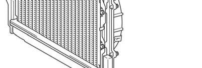
43 LH Side 25. DISCONNECT THE FRONT SPEED SENSOR CONNECTORS a) Disconnect the clamp and front speed sensor connector. b) Repeat the procedure on the opposite side. RH Side 26. REMOVE THE FOLLOWING PARTS Rear Quarter Panel Mudguard LH/RH Rear Bumper Assy. 27. REMOVE THE REAR BUMPER EXTENSION MOUNTING BRACKET W/ BACK STEP REINFORCEMENT a) Loosen the 4 bolts. b) Remove the 4 nuts and the rear bumper extension mounting bracket w/ back step reinforcement. 28. REMOVE/DISCONNECT THE FOLLOWING PARTS FROM ENGINE COMPARTMENT AREA Throttle Body Cover Air Cleaner Disconnect accelerator control cable (only on vehicles produced on or before August 2002) Radiator Inlet Hose (disconnect from engine) Radiator Outlet Hose (disconnect from engine) Disconnect Heater Coolant Hose Fan Shroud External Trans Cooler (If Equipped) Radiator Assy NOTE: After disconnecting the automatic transmission oil cooler hoses, plug them and cap the fittings to prevent the ATF from spilling out. 27
 a) Disconnect the 2 rear heater water hoses from the water pipe. 31.")
 Remove the bolt and the 2 nuts holding the engine wire harness connector from the cowl panel. c) Gently pull the engine wire harness out from body assembly.")
 Disconnect the connector and clamp from inner LH front fender. b) Remove the bolt and disconnect the ground wire.")
44 29. DISCONNECT THE FOLLOWING ENGINE COMPARTMENT HOSES a) Disconnect the brake booster hose. b) Disconnect the EVAP hose. c) Disconnect the air hose (for CCV). 30. DISCONNECT THE REAR HEATER WATER HOSES (IF EQUIPPED) a) Disconnect the 2 rear heater water hoses from the water pipe. 31. DISCONNECT THE ENGINE WIRE HARNESS a) Remove the bolt and disconnect the ground wire from cowl panel. b) Remove the bolt and the 2 nuts holding the engine wire harness connector from the cowl panel. c) Gently pull the engine wire harness out from body assembly. Note: Ensure all connectors have been previously disconnected from the glove compartment to ensure you do not damage the wire harness 32. DISCONNECT THE NO.2 ENGINE WIRE HARNESS a) Disconnect the connector and clamp from inner LH front fender. b) Remove the bolt and disconnect the ground wire. c) Remove the nut and disconnect the positive (+) battery cable. d) Remove the nut and 2 clamps and disconnect the No.2 engine wire harness from the junction block. 33. DISCONNECT THE A/C DISCHARGE HOSE AND SUCTION HOSE 28
45 34. DISCONNECT THE POWER STEERING PUMP OIL RESERVOIR a) Remove the 2 nuts and place the power steering reservoir on the engine assembly. D. REMOVAL OF THE BODY ASSY 35. REMOVE THE CAB BODY ASSY USING AN ABOVE GROUND LIFT Note: Before rolling chassis out, mark the location of the tires on the floor, this will help align the chassis when the cab is reinstalled. a) Remove the 8 nuts and 8 washers. b) Set the lift arms under the cab body assy. so they DO NOT interfere with the frame or cab mounts. c) Check that all wire harnesses, hoses, cables and the steering shaft are disconnected. d) Lift the cab assy. up slowly, making sure it does not interfere with anything while being raised. e) Raise the cab assy high enough so that the top of the engine clears the lowest point of the cab assy. f) Pull the frame assy out from under the cab assembly. g) Lower the cab assy all the way down and leave it on the lift. NOTE: Center the cab assy weight on the lift arms so that it does not slant/tilt to one side. Raise the cab assy slightly off the frame and verify that it is held securely by the lift arms. DO NOT work directly underneath the vehicle when pulling the frame assy. out from under it. DO NOT remove the cab mount bolts, as they will be used as guides during the cab assy. reinstallation process. 29

 SST: 09325-40010 No.")
46 E. DISASSEMBLE THE FRAME 1. PLACE THE FRAME ON A 2 nd LIFT a) Place the frame on the 2 nd lift, and secure it with a ratcheting tie down strap. This will prevent the frame from tilting or falling off as parts are removed. Ratcheting Tie Down: Qty: 1 Demensions: 2 in X 27 ft Minimum Work Load Capacity: 3,000 lbs 2. REMOVE THE FOLLOWING PARTS Spare Tire Carrier Receiver Hitch Bracket Assy (If Equipped) Front Propeller Shaft (4WD Only) Rear Propeller Shaft Insert the SST into the transmission after the rear propeller shaft is removed to prevent oil leakage. (2WD Only) SST: No.1 Fuel Tank Protector Fuel Tank Straps Fuel Tank NOTE: Make sure to place matchmarks on the front (if equipped) and rear propeller shafts before removal. 3. REMOVE THE EXHAUST SYSTEM a) Remove the clamp, 2 rear tail pipe brackets and rear tail pipe. b) Remove the 4 bolts, 2 exhaust pipe retainers, 4 exhaust pipe supports and center exhaust pipe. c) Remove the 3 exhaust pipe gaskets. 30

 8.")
47 4. DISCONNECT THE FUEL PIPE AND HOSE a) Remove the pulsation damper and disconnect the No.1 fuel pipe. b) Remove the 2 gaskets. c) Disconnect the No.1 fuel hose. NOTE: Put a shop towel under the delivery pipe. Slowly loosen the pulsation damper. 5. REMOVE THE DRIVE BELT 6. REMOVE AND SET A SIDE THE POWER STEERING PUMP ASSY a) Remove the 2 bolts and nut and power steering vane pump assy. NOTE: DO NOT disconnect the power steering pump hoses or lines. Make sure to keep the power steering pump reservoir in an upright position to prevent the fluid from leaking out. 7. DISCONNECT THE A.D.D. ACTUATOR CONNECTOR (4WD ONLY) 8. REMOVE THE ENGINE AND TRANSMISSION ASSY. a) Disconnect and remove the necessary items/parts to prepare the engine and transmission assy for removal. b) Remove the engine and transmission assy. NOTE: When removing the engine and transmission assy, ALWAYS use 2 engine hoists or mini cranes to lift it. DO NOT use 1 engine hoist or mini crane to lift the engine and transmission assy, as the unbalanced weight may lead to an accident or injury. ONLY use engine hoists or mini cranes that can properly support the weight of the engine and transmission assy. Carefully adjust the 2 engine hoists or mini cranes used so that the engine and transmission assy is properly balanced. 9. REMOVE THE 4 WHEELS 31
48 10. DISCONNECT THE REAR SPEED SENSOR CONNECTOR a) Remove the 2 clamps and disconnect the rear speed sensor connector. b) Repeat the procedure on the opposite side. 11. DISCONNECT THE NO.3 PARKING BRAKE CABLE a) Remove the bolt and disconnect the No.3 parking brake cable. 12. REMOVE THE NO.2 PARKING BRAKE CABLE a) Remove the clip. b) Remove the 2 bolts. c) Disconnect the No.2 parking brake cable from the 3 clamps. 13. DISCONNECT THE REAR BRAKE FLEXIBLE HOSES a) Using a flare nut wrench, disconnect the 2 rear brake tubes. b) Remove the bolt and disconnect the No.5 flexible hose bracket. 14. DISCONNECT THE REAR STABILIZER BAR a) Remove the 2 nuts and disconnect the 2 rear stabilizer links from the frame. b) Remove the 4 bolts, 2 brackets and rear stabilizer bar. 32
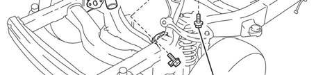
 Loosen the bolts and nuts of the rear suspension arms at the frame. 16.")
 Remove the 2 nuts and 2 retainers and disconnect the rear shock absorbers. 17.")
 Remove the 2 bolts, washer, nut and the rear lateral control rod (Illustration A).")
 Slowly lower the jack, and remove the rear coil springs and hollow springs (Illustration C).")
 Roll the rear axle assembly away from frame. Illustration A Illustration B Illustration C 18. DISCONNECT THE NO.")
49 15. LOOSEN THE REAR SUSPENSION ARMS a) Loosen the bolts and nuts of the rear suspension arms, at the rear axle housing. b) Loosen the bolts and nuts of the rear suspension arms at the frame. 16. DISCONNECT THE REAR SHOCK ABSORBERS a) Using a floor jack raise the rear axle housing. b) Remove the 2 nuts and 2 retainers and disconnect the rear shock absorbers. 17. REMOVE THE REAR AXLE HOUSING W/ LINK ASSY a) Position the floor jack underneath the center section of the rear axle to support during the disassembly process. b) Remove the 2 bolts, washer, nut and the rear lateral control rod (Illustration A). c) Remove the 2 bolts, 2 washers and 2 nuts and disconnect the No.1 rear suspension arms from the frame (Illustration B). d) Slowly lower the jack, and remove the rear coil springs and hollow springs (Illustration C). e) Remove the 2 bolts, 2 washers and 2 nuts and disconnect the lower control arms from the frame (Illustration C). f) Roll the rear axle assembly away from frame. Illustration A Illustration B Illustration C 18. DISCONNECT THE NO.1 FRONT BRAKE FLEXIBLE HOSES a) Disconnect the front brake tube. b) Remove the clip and disconnect the No.1 flexible hose. c) Plug the hose to ensure not rust or debris enter the brake hose d) Repeat the procedure on the opposite side. 33
 Tie Rod Ends Remove the cotter pins and nuts.")
 Remove the bolt, nut, 2 washers and front suspension upper arm w/ steering knuckle.")
 Remove Front Strut Assy by removing the three nuts and bolt. b) Repeat procedure on opposite side. c) Remove Front Suspension Lower Control Arm 23.")
50 19. DISCONNECT THE FRONT SPEED SENSOR CONNECTORS a) Remove the 2 bolts and 2 clamps and disconnect the front speed sensor connector. b) Repeat the procedure on the opposite side. 20. REMOVE THE FOLLOWING FRONT END COMPONENTS Front Bumper Reinforcement Front Stabilizer Bar Front Axle Shaft Nuts (4WD Only) Tie Rod Ends Remove the cotter pins and nuts. Using the SST, disconnect the tie rod ends. SST: Front Lower Ball Joints Remove the cotter pins and nuts. Using the SST, disconnect the lower ball joint. SST: REMOVE THE FRONT SUSPENSION UPPER ARMS W/ STEERING KNUCKLE AND STRUT ASSY a) Remove the bolt, nut, 2 washers and front suspension upper arm w/ steering knuckle. b) Repeat the procedure on the opposite side. NOTE: If the drive shaft is difficult to disconnect, tap it loose with a plastic hammer. 22. REMOVE FRONT STRUT ASSY AND LOWER CONTROL ARMS a) Remove Front Strut Assy by removing the three nuts and bolt. b) Repeat procedure on opposite side. c) Remove Front Suspension Lower Control Arm 23. REMOVE THE FOLLOWING POWERTRAIN COMPONENTS Power Steering Gear Assy w/ Power Steering Vane Pump Front Drive Shafts (4WD Only) Using the SST, remove the drive shafts. SST: , Front Differential Carrier (4WD Only) NOTE: When removing the power steering rack with the pump assy attached, have one person support the power steering rack and the other support the pump assy. Keep the power steering pump reservoir in an upright position to prevent fluid from leaking out. If the drive shaft is difficult to remove tap it with a plastic hammer. Be careful not to damage the dust cover and oil seal. 34
51 24. REMOVE THE FUEL TUBES a) Remove the bolts and clamps and the fuel tubes. NOTE: The number of fastening clips and clamps for the fuel tubes will differ depending on the vehicle model. Please verify the current vehicle and continue. 25. REMOVE THE STUD BOLT 26. REMOVE THE FRONT PARKING BRAKE CABLE RETAINER BRACKET AND CLAMPS a) Remove the bolt and the front cable retainer bracket from crossmember. b) Remove the 2 bolts and the clamps from crossmember and LH frame rail. c) Remove the clamp from RH side frame rail. 27. REMOVE THE REMAINING COMPONENTS Front Spring Bumpers Rear Spring Bumpers Cab Mounting Cushions (Qty: 8) 28. REMOVE THE FRAME FROM THE LIFT 35
52 F. ASSEMBLE THE NEW FRAME 1. PLACE THE NEW FRAME ON THE LIFT a) Place the NEW frame on the lift, and secure it with a ratcheting tie down strap. This will prevent the frame from tilting or falling off as parts are installed. Ratcheting Tie Down: Qty: 1 Demension: 2 in X 27 ft Minimum Work Load Capacity: 3,000 lbs NEW Replacement Parts Rear Spring Bumper Part Number Part Name Kit # Qty Bolt, w/washer REINSTALL THE REAR SPRING BUMPER a) Reinstall the rear spring bumper with the 2 NEW bolts and torque to spec. b) Repeat the procedure on the opposite side. Torque Spec: 29 N m (296 kgf cm, 21 ftlbf) 3. REINSTALL THE FRONT SPRING BUMPER a) Using the SST, reinstall the No.1 and No.2 front spring bumpers to the frame and torque to spec. b) Repeat the procedure on the opposite side. SST: Torque Spec: 31 Nm (316 kgf cm, 23 ft lbf) NEW Replacement Parts Lower Control Arm Cam Assy. Part Number Part Name Kit # Qty Cam Sub-Assy, Toe Adjust Plate, Toe Adjust No Bolt w/ Washer REINSTALL THE FRONT SUSPENSION LOWER CONTROL ARM a) Reinstall the front suspension lower control arm with 2 NEW bolts, 2 NEW toe adjustment plates, and 2 NEW toe adjustment cams, then torque to spec. Torque Spec: 130 Nm (1326 kgf cm, 96 ft lbf) b) Repeat the procedure on the opposite side. 36
 Reinstall the front parking brake cable retainer bracket with the bolt and torque to spec. Torque Spec: 26 N m (265 kgf cm, 19 ft lbf) 6.")
 NEW Replacement Parts Front Bumper Reinforcement Part Number Part Name Kit # Qty 90178-10024 Nut, Flange 1 4 NEW Replacement Parts Rear Bumper")
53 5. REINSTALL THE PARKING BRAKE CABLE RETAINER BRACKETS AND CLAMPS a) Reinstall the clamp. b) Reinstall the clamps with the 2 bolts and torque to spec. c) Reinstall the front parking brake cable retainer bracket with the bolt and torque to spec. Torque Spec: 26 N m (265 kgf cm, 19 ft lbf) 6. REINSTALL THE STEERING GEAR STUD BOLT a) Reinstall the stud bolt and torque to spec. Torque Spec: 20 N m (204 kgf cm, 15 ft lbf) NEW Replacement Parts Front Bumper Reinforcement Part Number Part Name Kit # Qty Nut, Flange 1 4 NEW Replacement Parts Rear Bumper Reinforcement Part Number Part Name Kit # Qty A0026 Bolt w/washer A0027 Bolt w/ Washer Nut, Hexagon Washer, Plate REINSTALL THE FRONT BUMPER REINFORCEMENT a) Reinstall the front bumper reinforcement with the 4 NEW nuts and torque to spec. Torque Spec: 50 N m (510 kgf cm, 37 ft lbf) 8. INSTALL THE REAR BUMPER REINFORCEMENT SET (If applicable) a) Install the rear bumper reinforcement set with the 6 NEW bolts, 6 NEW nuts and 6 NEW washers, then torque to spec. Torque Spec: 95 N m (970 kgf cm, 70 ft lbf) 9. REINSTALL THE CAB MOUNTS a) Reinstall the 8 cab mounts. Torque Spec: 61 N m (622 kgf cm, 45 ft lbf) 37
 NEW Replacement Parts Part Number Part Name Kit # Qty 47323-0C020 Tube, RR Brake, No.3 N/A* 1 47326-0C020 Tube, RR Brake, No.")
54 10. INSTALL THE NEW REAR BRAKE TUBES a) Install the NEW rear brake tubes with the 7 NEW clamps. b) Install the NEW 2 way with the NEW bolt and torque to spec. Torque Spec: 28 N m (286 kgf cm, 21 ft lbf) NEW Replacement Parts Part Number Part Name Kit # Qty C020 Tube, RR Brake, No.3 N/A* C020 Tube, RR Brake, No.6 N/A* Way, C06 Clamp B0816 Bolt w/ Washer 1 1 *Individual Part (s) 11. REINSTALL THE FUEL TUBES a) Reinstall the fuel tubes with the NEW bolts and NEW clamps, then torque to spec. Torque Specs: Clamp Bolt - 29 N m (296 kgf cm, 21 ft lbf) Filter Bolt - 20 N m (204 kgf cm, 15 ft lbf) NOTE:The number of bolts and clamps will differ depending on the vehicle specs. NEW Replacement Parts Part Number Part Name Kit # Qty Clamp, Fuel Tube, No.1 (TYPE A) Clamp, Fuel Tube, No.1 (TYPE B) Clamp, Fuel Tube, No.1 (TYPE C) Clamp, Fuel Tube, No.1 (TYPE E) Bolt, w/ Washer INSTALL THE NEW FRAME WIRE HARNESS a) Reconnect the clamps to install the NEW frame wire harness. b) Reconnect the ground wire with the bolt and torque to spec. Torque Spec: 29 N m (296 kgf cm, 21 ft lbf) NOTE: The number of clamps will differ depending on the vehicle specs. NEW Replacement Parts Part Number Part Name Kit # Qty C040 Wire, Frame
 Reinstall the front differential breather tube with the 2 clamps. Torque Spec: Bolt - 137 N m (1397 kgf cm, 101 ft lbf) Nut - 87 N m (887 kgf cm, 64 ft lbf) 14.")
 Bolt B - 165 N m (1682 kgf cm, 122 ft lbf) Nut 1-165 N m (1682 kgf cm, 122 ft lbf) Nut 2-130 N m (1326 kgf cm, 96 ft lbf) NOTE: When reinstalling")

55 13. REINSTALL THE FRONT DIFFERENTIAL CARRIER ASSY (4WD ONLY) a) Reinstall the front differential carrier assy with the 2 bolts, 4 stoppers and 3 nuts, then torque to spec. b) Reinstall the front differential breather tube with the 2 clamps. Torque Spec: Bolt N m (1397 kgf cm, 101 ft lbf) Nut - 87 N m (887 kgf cm, 64 ft lbf) 14. REINSTALL THE POWER STEERING LINK ASSY W/ POWER STEERING VANE PUMP a) Reinstall the power steering link assy w/ power steering vane pump with the 6 bolts, washer and 2 nuts, then torque to spec. Torque Spec: Bolt A - 29 N m (296 kgf cm, 21 ft lbf) Bolt B N m (1682 kgf cm, 122 ft lbf) Nut N m (1682 kgf cm, 122 ft lbf) Nut N m (1326 kgf cm, 96 ft lbf) NOTE: When reinstalling the power steering link with the vane pump attached, have one person support the power steering link and the other support the vane pump. Make sure to keep the power steering pump reservoir in an upright position to prevent the fluid from leaking out. 15. REINSTALL THE FRONT SHOCK ABSORBER ASSY a) Reinstall the front shock absorber assy with 3 nut (A) and torque to spec. b) Reinstall the front shock absorber assy to the lower control arm with the bolt and nut (B), then torque to spec. Torque Spec: Nut A - 64 N m (653 kgf cm, 47 ft lbf) Nut B N m (1377 kgf cm, 100 ft lbf) c) Repeat the procedure on the opposite side. NEW Replacement Parts Front Drive Shaft Part Number Part Name Kit # Qty Ring, Drive Shaft Snap N/A* 2 *Individual Part(s) 16. REINSTALL THE FRONT DRIVE SHAFTS (4WD ONLY) a) Install a NEW snap ring. b) Reinstall the front drive shaft. c) Repeat the procedure on the opposite side. NOTE: Be careful not to damage the dust cover and oil seal. 39
 b) Repeat the procedure on the opposite side. 18.")

 Repeat the procedure on the opposite side. Tie Rod Ends Reinstall the tie rod end with the nut and torque to spec. Install the NEW cotter pin.")

56 17. REINSTALL THE FRONT SUSPENSION UPPER ARM W/ STEERING KNUCKLE a) Reinstall the front suspension upper arm w/ steering knuckle with the bolt, nut and 2 washers, then torque to spec. Torque Spec: 98 N m (999 kgf cm, 72 ft lbf) b) Repeat the procedure on the opposite side. 18. REINSTALL THE FOLLOWING PARTS NEW Replacement Parts Front Lower Ball Joint Part Number Part Name Kit # Qty Pin, Cotter 1 2 Tie Rod End Part Number Part Name Kit # Qty Pin, Cotter 1 2 Front Stabilizer Bar Part Number Part Name Kit # Qty Bracket, Stabilizer, RH Bracket, Stabilizer, LH Bolt w/ Washer Nut, w/ Washer 1 2 Front Lower Ball Joints Reinstall the front lower ball joint with the nut and torque to spec. Install the NEW cotter pin. Torque Spec: 140 N m (1428 kgf cm, 103 ft lbf) Repeat the procedure on the opposite side. Tie Rod Ends Reinstall the tie rod end with the nut and torque to spec. Install the NEW cotter pin. Torque Spec: 91 N m (928 kgf cm, 67 ft lbf) Repeat the procedure on the opposite side. Front Axle Shaft Nuts (4WD Only) Temporarily install the front axle nut. This nut will be tightened when the vehicle is completed. Repeat the procedure on the opposite side. Front Stabilizer Bar Reinstall the stabilizer bar and 2 NEW brackets with the 2 NEW bolts and 2 NEW nuts, then torque to spec. Torque Spec: 37 N m (377 kgf cm, 27 ft lbf) Reinstall the stabilizer bar link with the 2 nuts and torque to spec. Torque Spec: 69 N m (704 kgf cm, 51 ft lbf) NEW Replacement Parts Front Speed Sensor Part Number Part Name Kit # Qty C010 Sensor, Speed, Front RH C010 Sensor, Speed, Front LH CONNECT THE NEW FRONT SPEED SENSORS a) Install the front speed sensor with the 3 bolts and 2 clamps, then torque to spec. Torque Spec: 8.0 N m (82 kgf cm, 71 inlbf) b) Repeat the procedure on the opposite side. 40
 Install the NEW bracket with the NEW bolt and torque to spec.")

 Reinstall the front brake tube and 2 way with the NEW bolt and torque to spec. Torque Spec: 28 Nm (286 kgf cm, 21 ftlbf) c) Reconnect the front brake tube and torque to spec.")
57 NEW Replacement Parts Front Brake Flex Hose Part Number Part Name Kit # Qty Bracket, Flexible Hose No Bracket, Flexible Hose No Clip B0816 Bolt, w/ Washer RECONNECT THE FRONT BRAKE FLEXIBLE HOSES a) Install the NEW bracket with the NEW bolt and torque to spec. Torque Spec: 28 N m (286 kgf cm, 21 ftlbf) b) Reconnect the flexible hose with the NEW clip. c) Repeat the procedure on the opposite side. NEW Replacement Parts Brake Tubes and 2 Way Part Number Part Name Kit # Qty C011 Tube, FR Brake, No C011 Tube, FR Brake, No Way, B0816 Bolt, w/ Washer INSTALL THE NEW FRONT BRAKE TUBES AND 2 WAYS a) Temporarily install the NEW front brake tube and NEW 2 way. b) Reinstall the front brake tube and 2 way with the NEW bolt and torque to spec. Torque Spec: 28 Nm (286 kgf cm, 21 ftlbf) c) Reconnect the front brake tube and torque to spec. Torque Spec: 16 Nm (163 kgf cm, 12 ftlbf) d) Repeat the procedure on the opposite side. 22. REINSTALL THE REAR AXLE HOUSING W/ LINK ASSY a) Place rear axle on floor jack and position under the frame. b) Temporarily reinstall the 2 bolts, 2 nuts and 2 washers on the frame side of the lower control arms to the frame. c) Set the rear coil springs and hollow springs on the rear axle housing. NOTE: After stabilizing the suspension, torque the bolts and nuts. Be sure to raise one side of the rear axle housing at a time. Install the rear lateral control rod after positioning the body on it. 41

 NEW Replacement Parts Rear Stabilizer Bar Part Number Part Name Kit # Qty 90080-11482 Bolt, w/ Washer 3 4 23.")
 b) Install the 4 NEW bolts and 2 brackets, then torque to spec.")
58 d) Raise the jack, and temporarily install the 2 bolts, 2 nuts and 2 washers on the frame side of the No.1 rear suspension arm to the frame. NOTE: After stabilizing the suspension, torque the bolt and nuts. Be sure to raise one side of the rear axle housing at a time. Install the rear lateral control rod after positioning the body on it. e) Reconnect the rear shock absorbers with the 2 nuts and 2 retainers, then torque to spec. Torque Spec: 58 N m (591 kgf cm, 43 ft lbf) NEW Replacement Parts Rear Stabilizer Bar Part Number Part Name Kit # Qty Bolt, w/ Washer RECONNECT THE REAR STABILIZER BAR a) Reconnect the 2 rear stabilizer links with the 2 nuts and torque to spec. Torque Spec: 69 N m (704 kgf cm, 51 ft lbf) b) Install the 4 NEW bolts and 2 brackets, then torque to spec. Torque Spec: 37 N m (377 kgf cm, 27 ft lbf) NEW Replacement Parts Rear Brake Flexible Hose Part Number Part Name Kit # Qty Bracket, Flexible Hose, No Clip B0816 Bolt, w/ Washer RECONNECT THE REAR BRAKE FLEXIBLE HOSES a) Install the No.5 flexible hose bracket with the NEW bolt and torque to spec. Torque Spec: 28 N m (286 kgf cm, 21 ft lbf) b) Reconnect the rear brake tubes and torque to spec. Torque Spec: 16 Nm (163 kgf cm, 12 ftlbf) 42
 26. RECONNECT THE NO.3 PARKING BRAKE CABLE a) Reconnect the No.3 parking brake cable with the bolt and torque to spec.")
 Install the new rear speed sensor b) Route the rear speed sensor connector and wire with the 2 clamps.")

59 25. REINSTALL THE NO.2 PARKING BRAKE CABLE a) Reconnect the No.2 parking brake cable to the 3 clamps. b) Reinstall the 2 bolts and torque to spec. c) Reinstall the clip. Torque Spec: 26 Nm (265 kgf cm, 19 ft lbf) 26. RECONNECT THE NO.3 PARKING BRAKE CABLE a) Reconnect the No.3 parking brake cable with the bolt and torque to spec. Torque Spec: 26 N m (265 kgf cm, 19 ft lbf) NEW Replacement Parts Rear Wheel Speed Sensors Part Number Part Name Kit # Qty C020 Sensor, Speed, Rear RH C020 Sensor, Speed, Rear LH CONNECT THE NEW REAR SPEED SENSOR CONNECTORS a) Install the new rear speed sensor b) Route the rear speed sensor connector and wire with the 2 clamps. c) Repeat the procedure on the opposite side. 28. REINSTALL THE 4 WHEELS 29. REINSTALL THE ENGINE AND TRANSMISSION ASSY a) Reinstall the engine and transmission assy. NOTE: When reinstalling the engine and transmission assy, ALWAYS use 2 engine hoists or mini cranes. DO NOT use 1 engine hoist or mini crane to lower the engine and transmission assy, as the unbalanced weight may lead to an accident/injury. ONLY use engine hoists or mini cranes that can properly support the weight of the engine and transmission assy. Carefully adjust the 2 engine hoists or mini cranes so that the engine and transmission assy is properly balanced. 43
 NEW Replacement Parts Engine Mounts Part Number Part Name Kit # Qty 90179-10071 Nut 1 4 NEW")

 31.")
60 b) Attach the engine mounts with the 4 bolts and 4 NEW nuts and torque to spec. Torque Spec: 38 N m (387 kgf cm, 28 ft lbf) NEW Replacement Parts Engine Mounts Part Number Part Name Kit # Qty Nut 1 4 NEW Replacement Parts Transmission Mount Part Number Part Name Kit # Qty Bolt, w/ Washer 3 4 c) Attach the transmission mount with 4 NEW bolts and torque to spec. Torque Spec: 18 N m (184 kgf cm, 13 ft lbf) d) Reinstall the items/parts that were removed during the engine and transmission assy removal. 30. RECONNECT THE A.D.D. ACTUATOR CONNECTOR (4WD ONLY) 31. REINSTALL THE POWER STEERING VANE PUMP ONTO ENGINE ASSEMBLY ASSY a) Reinstall the power steering vane pump assy to the mounting bracket with the 2 bolts and nut, then torque to spec. Torque Spec: 44 N m (449 kgf cm, 33 ft lbf) 44
 Always use 2 NEW gaskets. c) Tighten the pulsation damper by hand. d) Tighten the pulsation damper to the specified torque using the SST.")

 Connect the clamp and connector(s). 36. REINSTALL THE NO.1 FUEL TANK PROTECTOR a) Reinstall the No.1 fuel tank protector with the NEW bolts and NEW nuts, then torque to spec.")
61 32. REINSTALL THE DRIVE BELT NEW Replacement Parts Part Number Part Name Kit # Qty Gasket RECONNECT THE FUEL PIPES AND HOSE a) Reconnect the No.1 fuel hose. b) Always use 2 NEW gaskets. c) Tighten the pulsation damper by hand. d) Tighten the pulsation damper to the specified torque using the SST. SST: or equivalent Torque Spec: 39 N m (398 kgf cm, 29 ft lbf) 34. REINSTALL THE FUEL TANK STRAPS a) Reinstall the fuel tank straps with the 2 pins and 2 clips. NEW Replacement Parts Fuel Tank Straps Part Number Part Name Kit # Qty A0077 Bolt, w/ Washer REINSTALL THE FUEL TANK a) Reinstall the fuel tank with the 2 NEW bolts and torque to spec. Torque Spec: 62 N m (632 kgf cm, 46 ft lbf) b) Reinstall the fuel tubes. c) Connect the clamp and connector(s). 36. REINSTALL THE NO.1 FUEL TANK PROTECTOR a) Reinstall the No.1 fuel tank protector with the NEW bolts and NEW nuts, then torque to spec. Torque Specs: Bolt - 29 N m (296 kgf cm, 21 ft lbf) No.1 Fuel Tank Protector Part Number Part Name Kit # Qty Bolt, w/ Washer 3 5 NOTE: The number of fuel connectors will differ depending on the vehicle specs. 45
 Reinstall the center exhaust pipe with the 4 exhaust pipe supports, 2 NEW flange retainers and 4 bolts, then torque to spec.")
 NEW Replacement Parts Exhaust System Part Number Part Name Kit # Qty 18495-38020 Retainer, Converter RR Flange 1 2 90080-43034 Gasket, Exhaust System** NA*")
 a) Aligning the matchmarks, install the front propeller shaft to the transfer case and the front differential with the 8 bolts, 8 washers and 8")
62 37. REINSTALL THE EXHAUST SYSTEM a) Install the 3 NEW exhaust pipe gaskets. b) Reinstall the center exhaust pipe with the 4 exhaust pipe supports, 2 NEW flange retainers and 4 bolts, then torque to spec. Torque Spec: 48 N m (489 kgf cm, 35 ft lbf) c) Reinstall the tail exhaust pipe with the 2 tail pipe brackets. d) Face the clamp in the direction indicated in the illustration, and torque to spec. Torque Spec: 32 N m (326 kgf cm, 24 ft lbf) NEW Replacement Parts Exhaust System Part Number Part Name Kit # Qty Retainer, Converter RR Flange Gasket, Exhaust System** NA* Clamp Gasket, Exhaust System** NA* Gasket Exhaust System 1 1 *Individual Part(s) **Only 1 part # is used. The part # varies depending on vehicle model year. 38. REINSTALL THE FRONT PROPELLER SHAFT (4WD ONLY) a) Aligning the matchmarks, install the front propeller shaft to the transfer case and the front differential with the 8 bolts, 8 washers and 8 nuts, then torque to spec. Torque Spec: 74 N m (755 kgf cm, 55 ft lbf) NEW Replacement Parts Receiver Hitch Part Number Part Name Kit # Qty Bolt, w/ Washer REINSTALL THE RECEIVER HITCH BRACKET SUB-ASSY (IF EQUIPPED) a) Reinstall the receiver hitch bracket sub-assy with the 10 NEW bolts and torque to spec. Torque Spec: Bolt A N m (1071 kgf cm, 78 ft lbf) Torque Spec: Bolt B N m (1071 kgf cm, 78 ft lbf) 46
 Install the NEW spare tire carrier with the 4 NEW bolts and torque to spec.")
63 NEW Replacement Parts Spare Tire Carrier Part Number Part Name Kit # Qty Bolt, w/ Washer C020 Spare Tire Carrier NA* 1 *Individual Part(s) 40. INSTALL THE SPARE TIRE CARRIER a) Install the NEW spare tire carrier with the 4 NEW bolts and torque to spec. Torque Spec: 20 N m (204 kgf cm, 15 ft lbf) NOTE: Install the spare wheel after tightening the rear suspension arms. 41. REMOVE THE FRAME FROM THE LIFT a) Remove the ratcheting tie down strap from the frame. b) Lower the frame to the ground. G. REINSTALL THE CAB BODY ASSY NEW Replacement Parts Part Number Part Name Kit # Qty C012 Tube, FR Brake, No C040 Tube, FR Brake, No 6 NA* C030 Tube, FR Brake, No 2 NA* C020 Tube, FR Brake, No 5 NA* 1 *Individual Part(s) 1. INSTALL THE NEW ENGINE COMPARTMENT BRAKE LINE a) Install the NEW No.3 and NEW No.6 front brake tubes. b) Install the NEW No.2 and NEW No.5 rear brake tubes. c) Torque all brake tubes to spec. Torque Spec: 16 Nm (163 kgf cm, 12 ftlbf) NOTE: The number of clamps will differ depending on the vehicle spec. 47
 Lower the cab assy slowly, making sure it does not interfere with anything.")
 Once the cab assy is set on the mounts, secure it to the frame with the 8 bolts, 8 nuts and 8 washers and torque to spec. Torque Specs: No.1 and No.")
64 2. REINSTALL THE CAB BODY ASSY a) Raise the cab assy high enough so that the top of the engine clears the lowest point of the cab. b) Push the frame under the cab assy. Note: Line up the wheels with the alignment marks previously made to help align the frame with the cab. c) Lower the cab assy slowly, making sure it does not interfere with anything. d) Adjust the vehicle s frame as needed to align the cab mounts with the cab assy bolts. e) Once the cab assy is set on the mounts, secure it to the frame with the 8 bolts, 8 nuts and 8 washers and torque to spec. Torque Specs: No.1 and No.4 Nut - 47 N m (479 kgf cm, 35 ft lbf) Torque Specs: No.2 Nut - 54 N m (551 kgf cm, 40 ft lbf) Torque Specs: No.3 Nut - 67 N m (683 kgf cm, 50 ft lbf) NOTE: DO NOT work directly underneath the vehicle when pushing the frame under the cab assy. Slowly lower the cab body assy while making sure that the wire harness, steering shaft and hoses do not interfere with it. With 2 to 3 people checking for interference, slowly lower the cab body assy to the frame. Center the vehicle s weight on the lift arms so that it does not slant/tilt to one side. 3. READJUST LIFT ARMS AND LIFT VEHICLE 4. REMOVE THE FRONT WHEELS LH Side 5. RECONNECT THE FRONT SPEED SENSOR CONNECTORS a) Reconnect the front speed sensor connector. b) Reinstall the clamp. c) Repeat the procedure on the opposite side. RH Side 48
")


65 LH Side 6. RECONNECT THE FRONT BRAKE TUBES a) Reconnect the front brake tube and torque to spec. b) Repeat the procedure on the opposite side. Torque Spec: 16 Nm (163 kgf cm, 12 ftlbf) RH Side LH Side 7. REINSTALL THE FRONT FENDER APRON SEALS a) Reinstall the 4 front fender apron seals with the 21 clips. RH Side 49
 a) Reconnect the 2 rear heater water hoses to the water pipe.")
 Install the NEW O-rings to the discharge hose and suction hose. b) Reinstall the discharge hose and suction hose with the nuts and torque to spec.")
66 8. RECONNECT THE VANE PUMP OIL RESERVOIR a) Reinstall the vane pump oil reservoir with the 2 nuts and torque to spec. Torque Spec: 8.0 N m (82 kgf cm, 71 in lbf) 9. RECONNECT THE HEATER WATER HOSE 10. RECONNECT THE REAR HEATER WATER HOSES (IF EQUIPPED) a) Reconnect the 2 rear heater water hoses to the water pipe. NEW Replacement Parts A/C Line O-Rings Part Number Part Name Kit # Qty Ring, O RECONNECT THE A/C DISCHARGE HOSE AND SUCTION HOSE a) Install the NEW O-rings to the discharge hose and suction hose. b) Reinstall the discharge hose and suction hose with the nuts and torque to spec. Torque Spec: 10 N m (102 kgf cm, 7 ft lbf) 12. RECONNECT THE NO.2 ENGINE WIRE HARNESS a) Reinstall the No.2 engine wire harness with the nut and torque to spec. b) Reconnect the No.2 engine wire harness to the 2 clamps of the junction block. c) Reinstall the nut and reconnect the positive (+) battery cable and torque to spec. d) Reinstall the bolt and reconnect the ground wire to the LH side inner fender and torque to spec. e) Reconnect the connector and clamp. f) Reinstall the fuel pump relay. g) Reinstall the relay block cover. Torque Specs: Nut A - 10 N m (102 kgf cm, 7 ft lbf) Torque Specs: Nut B - 13 N m (133 kgf cm, 10 ft lbf) Torque Specs: Bolt N m (82 kgf cm, 71 in lbf) 50
 Install the NEW radiator drain cock plug O-ring.")
 d) Reconnect the upper and lower radiator hoses, automatic transmission cooler hoses. e) Reinstall the fan shroud.")
 17.")
67 13. RECONNECT THE FOLLOWING ENGINE COMPARTMENT HOSES a) Reconnect the EVAP hose b) Reconnect the air hose (for CCV) c) Reconnect the brake booster hose. NEW Replacement Parts Drain Cock O-Ring Part Number Part Name Kit # Qty Ring, O Radiator REINSTALL THE RADIATOR a) Install the NEW radiator drain cock plug O-ring. b) Tighten the radiator drain cock plug. c) Reinstall the radiator with the 4 bolts and torque to spec. Torque Spec: 12 N m (122 kgf cm, 9 ftlbf) d) Reconnect the upper and lower radiator hoses, automatic transmission cooler hoses. e) Reinstall the fan shroud. f) If equipped re-install external transmission cooler 15. RECONNECT THE ACCELERATOR CONTROL CABLE (ONLY FOR VEHICLES PRODUCED ON OR BEFORE SEPTEMBER 2002) 16. REINSTALL THE FOLLOWING PARTS Air Cleaner Throttle Body Cover Torque Spec: Nut N m (82 kgf cm, 71 in lbf) 17. RECONNECT THE ENGINE WIRE HARNESS a) Reinstall the engine wire harness connector with the 2 nuts and torque to spec. b) Reinstall the bolt and torque to spec. Torque Spec: 8.0 N m (82 kgf cm, 71 in lbf) c) Reconnect the ground wire to the cowl panel with the bolt and torque to spec. Torque Spec: 8.0 N m (82 kgf cm, 71 in lbf) NEW Replacement Parts Rear Bumper Extension Part Number Part Name Kit # Qty Nut, Flange A0064 Bolt, w/ Washer REINSTALL THE REAR BUMPER EXTENSION MOUNTING BRACKET W/ BACK STEP REINFORCEMENT a) Reinstall the rear bumper extension mounting bracket w/ back step reinforcement with the 4 NEW nuts and torque to spec. b) Install the 4 NEW bolts and torque to spec. Torque Spec: 19 N m (194 kgf cm, 14 ft lbf) 51
 Reconnect the front fender liners with the 2 screws. 21. RECONNECT THE AUTOMATIC TRANSMISSION NO.2 OIL COOLER OUTLET TUBE a) Reinstall the No.")
 NEW Replacement Parts Side Step Assy LH/RH Part Number Part Name Kit # Qty 90179-08068 Nut 1 6 90119-08516 Bolt, w/ Washer 1 10 22.")
68 19. REINSTALL THE FOLLOWING REAR BODY COMPONENTS Rear Bumper Cover Torque Spec: 7.0 N m (71 kgf cm, 62 in lbf) Rear Quarter Panel Mudguard LH/RH 20. RECONNECT THE FRONT FENDER LINER a) Reconnect the front fender liners with the 2 screws. 21. RECONNECT THE AUTOMATIC TRANSMISSION NO.2 OIL COOLER OUTLET TUBE a) Reinstall the No.2 oil cooler outlet tube with the bolt and torque to spec. b) Reconnect the hose. Torque Spec: 12 N m (122 kgf cm, 9 ft lbf) NEW Replacement Parts Side Step Assy LH/RH Part Number Part Name Kit # Qty Nut Bolt, w/ Washer REINSTALL THE FOLLOWING FRONT BODY PARTS Front Bumper Energy Absorber Front Bumper Cover Torque Spec: 7.0 N m (71 kgf cm, 62 in lbf) Front Fender Mudguard LH/RH Side Step Assy LH/RH with the 10 new bolts and 6 new nuts. Torque Spec: 20 Nm (204 kgf cm, 15 ftlbf) 23. RECONNECT THE FRAME WIRE a) Reconnect the connector and clamp(s) (For Charcoal Canister). b) Reconnect the connector(s) and clamp(s) (Receiver Hitch Equipped Vehicles Only). NOTE: The number of fastening connectors and clamps for the frame wire will differ depending on the vehicle model. Please verify the current vehicle and continue. Receiver Hitch Equipped Vehicle 52
69 NEW Replacement Parts Fuel Tank Filler and Breather Hose Clamps Part Number Part Name Kit # Qty Clamp, Hose RECONNECT THE FUEL TANK TO FILLER PIPE HOSE AND FUEL TANK BREATHER HOSE a) Reconnect the fuel tank to filler pipe hose with the 2 NEW clamps. b) Reconnect the fuel tank breather hose with the 2 NEW clamps. NOTE: Tighten the clamp of the fuel tank to filler pipe hose until it comes into contact with the stopper. 25. RECONNECT THE FUEL TANK VENT HOSE NOTE: After finishing the connection, check whether the pipe and the connector are securely connected by pulling them. 26. RECONNECT THE NO.1 PARKING BRAKE CABLE a) Reconnect the No.1 parking brake cable with the bolt and torque to spec. b) Reinstall the cable support bracket with the bolt and torque to spec. Torque Spec: 26 N m (265 kgfcm, 19 ft lbf) 53
 27. RECONNECT THE REAR BRAKE TUBES a) Using a flare nut wrench, connect the 2 rear brake tubes and torque to spec.")
70 c) Reconnect the No.2 parking brake cable with the clip and pin. d) Reconnect the No.1 parking brake cable to the No.3 parking brake cable and torque to spec. Torque Spec: 8.0 N m (82 kgf cm, 71 in lbf) 27. RECONNECT THE REAR BRAKE TUBES a) Using a flare nut wrench, connect the 2 rear brake tubes and torque to spec. Torque Spec: 16 Nm (163 kgf cm, 12 ftlbf) NEW Replacement Parts Intermediate Shaft Part Number Part Name Kit # Qty Bolt, w/ Washer RECONNECT THE NO.2 STEERING INTERMEDIATE SHAFT a) Make sure the spindles are in a straight-ahead position and the steering wheel is centered. b) Aligning the matchmarks, connect the No.2 steering intermediate shaft to the steering sliding yoke with the NEW bolt (A). c) Aligning the matchmarks, connect the No.2 steering intermediate shaft to the control valve shaft with the NEW bolt (B). d) Torque all bolts to spec. Torque Spec: 35 N m (357 kgf cm, 26 ft lbf) NEW Replacement Parts Auto Transmission Control Cable Part Number Part Name Kit # Qty Nut Washer, Plate RECONNECT THE TRANSMISSION CONTROL CABLE a) Reinstall the bolt and connect the transmission control cable and torque to spec. Torque Spec: 18 Nm (184 kgf cm, 13 ft lbf) b) Reinstall the pin or NEW nut and NEW washer, then torque to spec. Torque Spec: Nut- 13 N m (133 kgf cm, 10 ft lbf) (Only For Vehicles Produced On Or Before June 2003) Torque Spec: Nut- 15 Nm (153 kgf cm, 11 ft lbf) (Only For Vehicles Produced After June 2003) NOTE: Vehicles produced after August 2003 is not equipped with washer. 54
 Reconnect the connectors and clamp. NOTE: The number of connectors will differ depending on the vehicle specs.")
71 c) Reinstall the transmission control cable insulator with the 2 nuts and torque to spec. Torque Spec: 5.0 Nm (51 kgf cm, 44 in lbf) 30. REINSTALL FRONT WHEELS 31. LOWER THE VEHICLE 32. RECONNECT THE ENGINE WIRE HARNESS a) Reconnect the connectors and clamp. NOTE: The number of connectors will differ depending on the vehicle specs. Incorrectly connected connectors may cause the engine to start improperly. Be certain that the connectors are correctly connected. 33. RECONNECT THE FRAME WIRE CONNECTOR a) Reinstall the frame wire harness grommet. b) Reconnect the 2 connectors. 34. REINSTALL THE FOLLOWING INTERIOR COMPONENTS a) Glove Compartment No.4 Heater To Register Duct Lower No.2 Instrument Finish Panel Glove Compartment Door b) Center Console (4WD Only) Transfer High and Low Shift Lever No.1 Shift and Select Lever Boot Torque Spec: 7.0 N m (71 kgf cm, 62 in lbf) Upper Console Panel Shifting Hole Cover Transfer Shift Lever Knob c) Front Seat and Trim Front Seat RH Torque Spec: 37 N m (377 kgf cm, 27 ft lbf) Cowl Side Trim Board LH/RH Front Door Scuff Plate LH/RH 55
Please refer to the Frame Inspection Technical Instructions for the inspection procedure.
 To: Subject: All Toyota Dealer Principals, Service Manager, and Parts Managers (located in AK, AL, AR, AZ, CA, CO, FL, GA, HI, IA, ID, KS, LA, MO, MS, MT, NC, ND, NE, NM, NV, OK, OR, SC, SD, TN, TX, UT,
All Cold Climate States Toyota Dealer Principals, Service Manager, and Parts Managers
 To: Subject: All Cold Climate States Toyota Dealer Principals, Service Manager, and Parts Managers Limited Service Campaign (LSC) E0D 2005 through 2008 Model Year Tacoma Vehicles Corrosion-Resistant Compound
Certain Model Year Tacoma 2TR-FE Vehicles Exhaust Pipe Replacement for Catalytic Converter
 To: Subject: All Toyota Dealer Principals, Service Managers, and Parts Managers Special Service Campaign (SSC) F0U Certain 2010-2014 Model Year Tacoma 2TR-FE Vehicles Exhaust Pipe Replacement for Catalytic
A new brake reservoir assembly has been designed to prevent this condition from occurring.
 To: Subject: All Toyota Dealer Principals, Service Managers, and Parts Managers Limited Service Campaign (LSC) E0U 2007-2011 Model Year Camry Hybrid Vehicles Brake Reservoir Tank Replacement In our continuing
All Toyota Dealer Principals, Service Managers, Parts Managers. Certain 2010 Model Year Tacoma 4WD Vehicles Front Propeller Shaft
 To: Subject: All Toyota Dealer Principals, Service Managers, Parts Managers Safety Recall A0D Certain 2010 Model Year Tacoma 4WD Vehicles Front Propeller Shaft On February 11, 2010, Toyota filed a Defect
Remedy Procedure Phase 2 ( model year)
") To: Subject: All Toyota Dealer Principals, Service Managers, Parts Managers Safety Recall A0J Certain 2005 through 2008 Toyota Corolla and Corolla Matrix Vehicles Equipped with 1ZZ-FE Electronic Control
To: Subject: All Toyota Dealer Principals, Service Managers, Parts Managers Safety Recall A0J Certain 2005 through 2008 Toyota Corolla and Corolla Matrix Vehicles Equipped with 1ZZ-FE Electronic Control
The owner notification will commence in late July, 2006, approximately one week after the dealer notification.
 TO: SUBJECT: ALL TOYOTA DEALER PRINCIPALS, SERVICE MANAGERS, PARTS MANAGERS SPECIAL SERVICE CAMPAIGN (SSC) 60F (SAFETY RECALL) 2004 THROUGH 2005 HIGHLANDER AND EARLY 2006 HIGHLANDER HV CENTER CONSOLE (FLOOR
All Toyota Dealer Principals, Service Managers, and Parts Managers
 To: All Toyota Dealer Principals, Service Managers, and Parts Managers Subject: Safety Recall C0U Remedy Parts Available 2004 to Certain 2009 Model Year Prius Vehicles Hybrid Electric Water Pump As previously
Owner letters will be mailed based upon part number and production date, starting with earlier production vehicles.
 TO: ALL TOYOTA DEALER PRINCIPALS, SERVICE MANAGERS, PARTS MANAGERS SUBJECT: SPECIAL SERVICE CAMPAIGN (SSC) 50J PHASE 1 (FRONT SUSPENSION LOWER BALL JOINT) As announced in May, 2005, Toyota will initiate
All Toyota Dealer Principals, Service Managers, and Parts Managers
 To: Subject: All Toyota Dealer Principals, Service Managers, and Parts Managers Extension of Limited Service Campaign (LSC) 90K Certain 2005-2009 Model Year Avalon, Certain -2010 Model Year Camry, Certain
TECHNICAL INSTRUCTIONS FOR LIMITED SERVICE CAMPAIGN (LSC) A0F 2000 THROUGH 2003 MODEL YEAR TUNDRA FRAME REPLACEMENT
 A0F 2000 THROUGH 2003 MODEL YEAR TUNDRA FRAME REPLACEMENT") TECHNICAL INSTRUCTIONS FOR LIMITED SERVICE CAMPAIGN (LSC) A0F 2000 THROUGH 2003 MODEL YEAR TUNDRA FRAME REPLACEMENT I. OPERATION FLOWCHART Verify Vehicle Eligibility 1. Check the VIN range. 2. Check the
TECHNICAL INSTRUCTIONS FOR LIMITED SERVICE CAMPAIGN (LSC) A0F 2000 THROUGH 2003 MODEL YEAR TUNDRA FRAME REPLACEMENT I. OPERATION FLOWCHART Verify Vehicle Eligibility 1. Check the VIN range. 2. Check the
All Toyota Dealer Principals, Service Managers, and Parts Managers
 To: All Toyota Dealer Principals, Service Managers, and Parts Managers Subject: Safety Recall BSJ (Supplement to B0J) Certain 2006 and 2007 Model Year Highlander Hybrid Vehicles (HV) Intelligent Power
* * * * * * * * * * * * * * * * * * * * * * * * * * * * * * * * * * * * * * * * * * * * * * * * * * * * * * * * * *
 TECHNICAL INSTRUCTIONS FOR LIMITED SERVICE CAMPAIGN CSD * * * * * * * * * * * * * * * * * * * * * * * * * * * * * CERTAIN 2001-2004 MODEL YEAR SEQUOIA * * * * * * * * * * * * * * * * * * * * * * * * *
The following information is provided to inform you and your staff of the program notification schedule and your degree of involvement.
 To: Subject: All Toyota Dealer Principals, Service Managers, Parts Managers Warranty Enhancement ZTV 2004 to Certain 2009 Model Year Prius Vehicles Extension of Warranty Coverage for Combination Meter
CustomerServicesDivision
 CustomerServicesDivision Toyota Motor Sales, U.S.A., Inc. 19001 South Western Avenue P.O. Box 2991 Torrance, CA 90509-2991 TO: SUBJECT: ALL TOYOTA DEALER PRINCIPALS, SERVICE MANAGERS, PARTS MANAGERS SPECIAL
All Toyota Dealer Principals, General Managers, Service Managers, and Parts Managers
 Toyota Motor Sales, USA, Inc. 19001 South Western Avenue Torrance, CA 90501 (310) 468-4000 Original Publication Date: June 1, 2017 To: Subject: All Toyota Dealer Principals, General Managers, Service Managers,
All Toyota Dealer Principals, Service Managers, Parts Managers
 To: Updated: 9/03/2014 FJ Cruiser Tire and Loading Information Labels Updated All Toyota Dealer Principals, Service Managers, Parts Managers Subject: Non-Compliance Campaign - B0B Phase 2 Certain 2008
All Toyota Dealer Principals, General Managers, Service Managers, and Parts Managers
 TOYOTA Published November 3, 2016 Toyota Motor Sales, USA, Inc. 19001 South Western Avenue Torrance, CA 90501 (310) 468-4000 To: Subject: All Toyota Dealer Principals, General Managers, Service Managers,
The owner notification will commence in early March, 2010, approximately one week after the dealer notification.
 To: All Toyota Dealer Principals, Service Managers, Parts Managers Subject: Limited Service Campaign (LSC) 90K Phase 3 2007 2009 Model Year Avalon and RAV4 Vehicles Equipped with the V6 (2GR-FE) Engine
The owner notification will commence in mid-february, 2010, approximately one week after the dealer notification.
 To: All Toyota Dealer Principals, Service Managers, Parts Managers Subject: Limited Service Campaign (LSC) 90K Phase 2 2007 Early 2010 Model Year Camry Vehicles Equipped with the V6 (2GR-FE) Engine VVT-I
All Toyota Dealer Principals, Service Managers, Parts Managers
 To: Subject: All Toyota Dealer Principals, Service Managers, Parts Managers Warranty Enhancement Program ZE7 Certain 2007-2009 Camry Certain 2007-2011 Camry Hybrid Certain 2007-2008 Camry Solara Certain
Lexus has completed the remedy preparations and will begin mailing the remedy owner letter for Safety Recall ELF.
 February 11, 2015 Subject: Safety Recall ELF (E2F) Remedy Available 2007 through 2010 Model Year LS Vehicles 2006 through 2011 Model Year GS and IS Vehicles 2010 Model Year IS C Vehicles 2008 through 2010
CT, DE, IL, IN, KY, MA, MD, ME, MI, MN, NH, NJ, NY, OH, PA, RI, VA, VT, WI & WV
 To: Subject: All Toyota Dealer Principals, Service Managers, Parts Managers Safety Recall (Special Service Campaign) 90M Certain 2000 2003 Model Year Toyota Tundra Vehicle in Severe Cold Climate States
All Dealer Principals, General Managers, Service Managers, and Parts Managers
 April 19, 2016 To: Subject: All Dealer Principals, General Managers, Service Managers, and Parts Managers Warranty Enhancement Program - ZLG Certain 2006 2007 GS 430, 2007 2011 GS 450h, 2008 2011 GS 460,
TOYOTA IMPORTANT UPDATE
 TOYOTA IMPORTANT UPDATE Product Support Division The attached Dealer Letter has been updated. Refer to the details below. DATE TOPIC The Toyota Rent-A-Car (TRAC) & Service Loaners section has been updated.
The following vital information is provided to inform you and your staff of the program notification schedule and your degree of involvement.
 To: Subject: All Toyota Dealer Principals, Service Managers, Parts Managers Customer Support Program (CSP) Specific Malfunction Indicator Light ON and/or Harsh Shift of Automatic Transaxle on Certain 2001
TOYOTA IMPORTANT UPDATE
 TOYOTA IMPORTANT UPDATE Product Support Division The attached Dealer Letter has been updated, refer to the details below. DATE February 11, 2016 TOPIC Remedy is now available for Phase 2, New York Region.
1. Owner Notification Letter Mailing Date
 TO: SUBJECT: ALL TOYOTA DEALER PRINCIPALS, SERVICE MANAGERS, PARTS MANAGERS SPECIAL SERVICE CAMPAIGN (SAFETY RECALL) 60H (2005 THROUGH LATE 2006 MODEL YEAR SCION tc SIDE IMPACT AIRBAG SENSORS) Toyota will
The following information is provided to inform you and your staff of the remedy notification phase.
 To: Subject: All Toyota Dealer Principals, Service Managers, Parts Managers Safety (Non-Compliance) Recall BSN Supplemental Phase for Vehicles with Specific Accessories 2011 and Certain early 2012 Model
The following information is provided to inform you and your dealers of this campaign and your degree of involvement.
 To: Subject: All Toyota Dealer Principals, Service Managers, Parts Managers TRD High Performance Brake Kit Accessory Equipment Recall Designed to fit 2007 to 2012 Model Year FJ Cruiser Vehicles Safety
Safety Recall E0G Remedy Available 2003 and 2004 Model Year Avalon Vehicles Supplemental Restraint System (SRS) Electronic Control Module (ECM)
 Electronic Control Module (ECM)") To: Subject: All Toyota Dealer Principals, Service Managers, and Parts Managers Safety Recall E0G Remedy Available 2003 and 2004 Model Year Avalon Vehicles Supplemental Restraint System (SRS) Electronic
To: Subject: All Toyota Dealer Principals, Service Managers, and Parts Managers Safety Recall E0G Remedy Available 2003 and 2004 Model Year Avalon Vehicles Supplemental Restraint System (SRS) Electronic
IMPORTANT UPDATE. The attached Dealer Letter has been updated. Refer to the details below.
 IMPORTANT UPDATE The attached Dealer Letter has been updated. Refer to the details below. DATE December 5, 2018 TOPIC Loaner Vehicle Reimbursement Procedure section has been updated with Op Codes for vehicle
TOYOT. CUSTOMER SERVICES
 TOYOT. CUSTOMER SERVICES, -' 79 :INTE~O'FF.~CE MEMORANDUM Volume: Number: TCO6-011 Date: 0711812006 - X Action X Retain - Information TO: ALL MANAGERS1 FROM: DAVE ZELLERS, & SERVICE SUPPORT SUBJECT: SPECIAL
TECHNICAL INSTRUCTIONS FOR LIMITED SERVICE CAMPAIGN ESD * * * * * * * * * * * * * * * * * * * * * * * * * * * * *
 TECHNICAL INSTRUCTIONS FOR LIMITED SERVICE CAMPAIGN ESD * * * * * * * * * * * * * * * * * * * * * * * * * * * * * CERTAIN 2005 THROUGH 2008 MODEL YEAR TACOMA * * * * * * * * * * * * * * * * * * * * * *
Please find attached the Dealer Notification Preliminary Letter for Toyota Safety Recall 14V-312 on the following Toyota and Lexus vehicles:
 TMS-NTC-14104 June 18, 2014 Toyota Motor Sales, U.S.A., Inc. 19001 South Western Avenue, S207 Torrance, CA 90509-2991 Recall Management Division National Highway Traffic Safety Administration 1200 New
SPECIAL SERVICE CAMPAIGN (SSC) 60C (SAFETY RECALL) (2004 THROUGH EARLY 2006 STEERING INTERMEDIATE SHAFT REPLACEMENT)
 60C (SAFETY RECALL) (2004 THROUGH EARLY 2006 STEERING INTERMEDIATE SHAFT REPLACEMENT)") TO: SUBJECT: ALL TOYOTA DEALER PRINCIPALS, SERVICE MANAGERS, PARTS MANAGERS SPECIAL SERVICE CAMPAIGN (SSC) 60C (SAFETY RECALL) (2004 THROUGH EARLY 2006 STEERING INTERMEDIATE SHAFT REPLACEMENT) Toyota will
TO: SUBJECT: ALL TOYOTA DEALER PRINCIPALS, SERVICE MANAGERS, PARTS MANAGERS SPECIAL SERVICE CAMPAIGN (SSC) 60C (SAFETY RECALL) (2004 THROUGH EARLY 2006 STEERING INTERMEDIATE SHAFT REPLACEMENT) Toyota will
CustomerServicesDivision Toyota Motor Sales, U.S.A., Inc South Western Avenue P.O. Box 2991 Torrance, CA
 CustomerServicesDivision Toyota Motor Sales, U.S.A., Inc. 19001 South Western Avenue P.O. Box 2991 Torrance, CA 90509 2991 TO: ALL TOYOTA DEALER PRINCIPALS, SERVICE MANAGERS, PARTS MANAGERS SUBJECT: SPECIAL
All Toyota Dealer Principals, General Managers, Service Managers, and Parts Managers
 Toyota Motor Sales, USA, Inc. 6565 Headquarters Drive Plano, TX 75024 (469) 292-4000 Original Publication Date: March 29, 2018 To: Subject: All Toyota Dealer Principals, General Managers, Service Managers,
Re: Toyota Safety Recall 12V-537 Dealer Notification Remedy Phase 1, Interim Phase 2
 TMS-NTC-12304 December 17, 2012 Toyota Motor Sales, U.S.A., Inc. 19001 South Western Avenue, S207 Torrance, CA 90509-2991 Recall Management Division National Highway Traffic Safety Administration 1200
Safety Recall Remedy Toyota dealers are requested to replace the Steering Column Upper Bracket at NO CHARGE to the vehicle owner.
 To: Subject: All Toyota Dealer Principals, Service Managers, Parts Managers Voluntary Safety Recall A0H Certain 2000 through 2004 Toyota Avalon Steering Column Upper Bracket Replacement As communicated
4/7/2016 6/9/2015 P/N /29/2015 MAC
 Updated: 4/7/2016 Sublet Correction for Coolant Cost Updated: 6/9/2015 P/N 08833-80090 Removed from Part Ordering Process Updated: 5/29/2015 MAC Process and Part Number Update Updated: 8/12/2014 Repair
SPECIAL SERVICE CAMPAIGN (SSC) 10F ( MY ECHO AND AVALON TETHER ANCHOR UPGRADE)
 10F ( MY ECHO AND AVALON TETHER ANCHOR UPGRADE)") TO: SUBJECT: ALL TOYOTA DEALER PRINCIPALS, SERVICE MANAGERS, PARTS MANAGERS SPECIAL SERVICE CAMPAIGN (SSC) 10F (2000-2001 MY ECHO AND AVALON TETHER ANCHOR UPGRADE) Toyota will initiate a Special Service
TO: SUBJECT: ALL TOYOTA DEALER PRINCIPALS, SERVICE MANAGERS, PARTS MANAGERS SPECIAL SERVICE CAMPAIGN (SSC) 10F (2000-2001 MY ECHO AND AVALON TETHER ANCHOR UPGRADE) Toyota will initiate a Special Service
TECHNICAL INSTRUCTIONS FOR SPECIAL SERVICE CAMPAIGN ESS CURRENTLY REGISTERED OUTSIDE OF THE 20 COLD CLIMATE STATES
 TECHNICAL INSTRUCTIONS FOR SPECIAL SERVICE CAMPAIGN ESS CURRENTLY REGISTERED OUTSIDE OF THE 20 COLD CLIMATE STATES SPARE TIRE CARRIER CABLE REPLACEMENT 2004 2011 MY SIENNA (2WD) VEHICLES EQUIPPED WITH
Safety Recall H46 - Mopar Steering Linkage
 Dealer Service Instructions for: Revised May 2009 Safety Recall H46 - Mopar Steering Linkage NOTE: The service procedure for this recall has been revised and additional labor operations have been added.
#06083: Product Safety - Crankshaft Position Sensor Engine Stall - (Dec 11, 2007)
") Page 1 of 6 2001 Chevrolet Chevy K Silverado - 4WD Sierra, Silverado, Suburban, Tahoe, Yukon (VIN C/K) Service Manual Campaigns Safety Document ID: 2044115 #06083: Product Safety - Crankshaft Position
Page 1 of 6 2001 Chevrolet Chevy K Silverado - 4WD Sierra, Silverado, Suburban, Tahoe, Yukon (VIN C/K) Service Manual Campaigns Safety Document ID: 2044115 #06083: Product Safety - Crankshaft Position
SERVICE PROGRAM BULLETIN
 ATTENTION: GENERAL MANAGER PARTS MANAGER CLAIMS PERSONNEL SERVICE MANAGER IMPORTANT - All Service Personnel Should Read and Initial SERVICE PROGRAM BULLETIN APPLICABILITY: SUBJECT: 2000MY Subaru Legacy
Dealer Service Instructions for: Safety Recall G15 Rear Wheel Hub Mounting Bolts
 Dealer Service Instructions for: Safety Recall G15 Rear Wheel Hub Mounting Bolts May 2007 Models 2007 (MK) Jeep Compass and Patriot 2007 (PM) Dodge Caliber NOTE: This recall applies only to the above vehicles
Dealer Service Instructions for: Safety Recall H37 Gearshift Cable
 Dealer Service Instructions for: Safety Recall H37 Gearshift Cable Revised December 2008 Please remove and discard from your files all prior copies of Safety Recall H37 (dated November 2008). The repair
Appx. Number of. Highlander 135,400 Highlander HV 23,200
 To: Subject: All Toyota Dealer Principals, Service Managers, and Parts Managers Safety Recall - C0M Remedy Notification Multiple Models and Model Years Power Window Master Switch (PWMS) As previously announced,
(DM) RAM Truck (4500/5500 Cab Chassis) (DP) RAM Truck (4500/5500 Cab Chassis)
 RAM Truck (4500/5500 Cab Chassis) (DP) RAM Truck (4500/5500 Cab Chassis)") Dealer Service Instructions for: Safety Recall R16 / NHTSA 13V-527 Steering Linkage May 2015 NOTE: Safety Recall N63 is being cancelled. All vehicles involved in Safety Recall N63 must have this recall
Dealer Service Instructions for: Safety Recall R16 / NHTSA 13V-527 Steering Linkage May 2015 NOTE: Safety Recall N63 is being cancelled. All vehicles involved in Safety Recall N63 must have this recall
Condition. Correction. Vehicles Involved. xtooltipelement
 xtooltipelement #05500: Product Emission - Ignition Distributor System Corrosion-Inspect/Replace - (Apr 28, 2005) Subject: 05500 -- IGNITION DISTRIBUTOR SYSTEM CORROSION - INSPECT / REPLACE Models: 2001-2003
Problem Description It is possible that the dust/moisture seals of the affected vehicles tie rods may not seal properly resulting in premature wear.
 Recall Circular Subject: 1999 Volkswagen Passat Vehicles Replace Tie Rod Ends Code: WL January 2001 Dear Volkswagen Dealer: This is to inform you of the initiation of a voluntary safety recall involving
INTERIM RECALL NOTICE
 IMPORTANT SAFETY RECALL DEPARTMENT OF COMPLIANCE VEHICLE SAFETY AND RECALL MANAGEMENT BUILDING 11 423 N MAIN ST MIDDLEBURY, INDIANA 46540-9218 INTERIM RECALL NOTICE NHTSA RECALL: 17V446 FORD RECALL NUMBER:
Safety Recall Code: 46G4
 Safety Recall Code: 46G4 Subject Brake Pedal Clip Release Date April 5, 2016 Affected Vehicles U.S.A. & CANADA: 2011-2016 Model Year Volkswagen Touareg Vehicles Check Campaigns/Actions screen in Elsa on
Service Bulletin
 Service Bulletin 12-057 Applies To: 2007 11 Element ALL September 19, 2012 Safety Recall: Accessory Trailer Hitch Wire Harness Is Mis-Wired (Supersedes 12-057, dated August 31, 2012, to revise the information
SAFETY RECALL. CERTAIN YZF-R3F/G MODELS FACTORY MODIFICATION CAMPAIGN Clutch Pressure Plate and Oil Pump
 MOTORCYCLE 7/6/2016 M2016-005R 2016 YAMAHA MOTOR CORPORATION, U.S.A. SAFETY RECALL This modification has top priority. This bulletin must be performed immediately to ensure customer safety. NOTE: Bulletins
December 2004 Distributor/Dealer Service Instructions for: Safety Recall D55 Right Steering Knuckle. Models
 December 2004 Distributor/Dealer Service Instructions for: Safety Recall D55 Right Steering Knuckle Models 2005 (JR) Dodge Stratus Sedan and Chrysler Sebring Sedan/Convertible NOTE: This recall applies
CARFAX Vehicle History Report for this 2009 TOYOTA TACOMA ACCESS CAB: 5TETX22N59Z Accident reported. CARFAX 1-Owner vehicle.
 For Personal Use Only Vehicle Information: 2009 TOYOTA TACOMA ACCESS CAB VIN: 5TETX22N59Z637945 PICKUP 2.7L I4 F DOHC 16V GASOLINE REAR WHEEL DRIVE Standard Equipment Safety Options Accident reported CARFAX
Dealer Service Instructions for: Safety Recall N28 / NHTSA 13V-234 Transmission Oil Cooler Tube
 Dealer Service Instructions for: Safety Recall N28 / NHTSA 13V-234 Transmission Oil Cooler Tube September 2013 Models 2012-2013 (JK) Jeep Wrangler NOTE: This recall applies only to the above vehicles equipped
Emissions Recall Circular
 IMPORTANT INFORMATION Please inform and provide a copy of this document to every person in your dealership with campaign-related responsibilities, including Service, Parts and Accounting personnel. By
Director P. O. Box 1904 Service Engineering Operations Dearborn, Michigan Ford Customer Service Division
 Michael A. Berardi Ford Motor Company Director P. O. Box 1904 Service Engineering Operations Dearborn, Michigan 48121 Ford Customer Service Division TO: All U.S. Ford and Lincoln Dealers June 27, 2017
SERVICE BULLETIN NUMBER: R DATE: 10/26/15 REVISED: 11/19/15. APPLICABILITY: MY Legacy and Outback Models SUBJECT:
 ATTENTION: GENERAL MANAGER q PARTS MANAGER q CLAIMS PERSONNEL q SERVICE MANAGER q IMPORTANT - All Service Personnel Should Read and Initial in the boxes provided, right. 2015 Subaru of America, Inc. All
FILE: SERVICE: GROUP 00 OF SERVICE INFORMATION BINDER PARTS: GROUP I OF INFORMATION _ PARTS & ACCESSORIES BINDER
 FILE: SERVICE: GROUP 00 OF SERVICE INFORMATION BINDER PARTS: GROUP I OF INFORMATION _ PARTS & ACCESSORIES BINDER Campaign No. 2006080004, November 2006 Revision History Revision Date Purpose A 11/03/06
IMPORTANT: A small number of the above vehicles have already been reprogrammed and, therefore, have been excluded from this recall.
 Dealer Service Instructions for: Safety Recall No. C33 Reprogram BCM Vehicle Lighting November 2003 Models 2003 (ZB) Dodge Viper IMPORTANT: A small number of the above vehicles have already been reprogrammed
December 2000 Dealer Service Instructions for:
 December 2000 Dealer Service Instructions for: Safety Recall No. 964 -- Starter Terminal Block Models 2001 (PL) Dodge Neon R/T NOTE: This recall applies only to the above vehicles equipped with a 2.0L
December 2004 Distributor/Dealer Service Instructions for: Safety Recall D47 - Upper Ball Joints (AN) Dodge Dakota 4x4 Pick-Up Truck
 Dodge Dakota 4x4 Pick-Up Truck") December 2004 Distributor/Dealer Service Instructions for: Safety Recall D47 - Upper Ball Joints Models 2000-2003 (AN) Dodge Dakota 4x4 Pick-Up Truck 2000-2003 (DN) Dodge Durango 4x4 NOTE: This notification
December 2004 Distributor/Dealer Service Instructions for: Safety Recall D47 - Upper Ball Joints Models 2000-2003 (AN) Dodge Dakota 4x4 Pick-Up Truck 2000-2003 (DN) Dodge Durango 4x4 NOTE: This notification
F/CMVSS Noncompliance Recall Electronic Brake Control Module Memory Failure
 Reference Number: N162039440 Release Date: December 2017 Revision: 01 Revision Description: The Service Procedure and the Warranty Information sections have been revised. Effective immediately, technicians
SAFETY RECALL VT750 SERIES - BANK ANGLE SENSOR REPLACEMENT. (This bulletin supersedes VT750C/C2B #5, dated June 2011)
") Honda is launching a Safety Recall of 2010-2016 model year VT750C/CA/CS, VT750C2/ C2F/C2S, and VT750C2B motorcycles for a potentially defective bank angle sensor. Honda has determined that continuous engine
Honda is launching a Safety Recall of 2010-2016 model year VT750C/CA/CS, VT750C2/ C2F/C2S, and VT750C2B motorcycles for a potentially defective bank angle sensor. Honda has determined that continuous engine
AUDI DEALER COMMUNICATION
 AUDI DEALER COMMUNICATION Status Update Safety Recall 19N4 After-Run Coolant Pump This notice is for: Dealer Principal Service Manager Warranty Administrator General Manager Parts Manager Technicians Sales
TECHNICAL INSTRUCTIONS FOR SPECIAL SERVICE CAMPAIGN A7E ORIGINALLY SOLD IN AND CURRENTLY REGISTERED IN
 TECHNICAL INSTRUCTIONS FOR SPECIAL SERVICE CAMPAIGN A7E ORIGINALLY SOLD IN AND CURRENTLY REGISTERED IN AL, AK, AZ, AR, CA, CO, FL, GA, HI, ID, IA, KS, LA, MS, MO, MT, NE, NV, NM, NC, ND, OK, OR, SC, SD,
Dealer Service Instructions for: Customer Satisfaction Notification L10 Coolant Reservoir Outlet Hose
 Dealer Service Instructions for: Customer Satisfaction Notification L10 April 2011 Effective immediately all repairs on involved vehicles are to be performed according to this notification. Rapid Response
June 21, All U.S. Ford and Lincoln Dealers
 Michael A. Berardi Director Service Engineering Operations Ford Customer Service Division TO: All U.S. Ford and Lincoln Dealers Ford Motor Company P. O. Box 1904 Dearborn, Michigan 48121 June 21, 2013
Subject: Brake Light Pressure Switches. Models Affected: Specific Freightliner Cascadia and Western
 Subject: Brake Light Pressure Switches Models Affected: Specific Freightliner Cascadia and Western Star 4700, 4900, 5700, 6900 model vehicles manufactured March 27, 2007, through November 21, 2017. General
TOYOTA IMPORTANT UPDATE
 TOYOTA IMPORTANT UPDATE Product Support Division The attached Dealer Letter has been updated. Refer to the details below. DATE TOPIC 1/12/2017 Additional information for Phase Two launch has been added.
Safety Recall D21 Rear Floorpan Reinforcement Spot Welds
 Dealer Service Instructions for: July 2004 Safety Recall D21 Rear Floorpan Reinforcement Spot Welds Models 2005 (LX) Chrysler 300 and Dodge Magnum NOTE: This recall applies only to the certain vehicles
TECHNICAL INSTRUCTIONS FOR LIMITED SERVICE CAMPAIGN (LSC) A0N HV WATER PUMP REPLACEMENT MODEL YEAR PRIUS
 A0N HV WATER PUMP REPLACEMENT MODEL YEAR PRIUS") TECHNICAL INSTRUCTIONS FOR LIMITED SERVICE CAMPAIGN (LSC) A0N HV WATER PUMP REPLACEMENT 2004 2007 MODEL YEAR PRIUS I. OPERATION FLOWCHART II. IDENTIFICATION OF AFFECTED VEHICLES A. AFFECTED VIN RANGE Model
TECHNICAL INSTRUCTIONS FOR LIMITED SERVICE CAMPAIGN (LSC) A0N HV WATER PUMP REPLACEMENT 2004 2007 MODEL YEAR PRIUS I. OPERATION FLOWCHART II. IDENTIFICATION OF AFFECTED VEHICLES A. AFFECTED VIN RANGE Model
(LX) Chrysler 300, Chrysler 300 SRT8, Dodge Charger and Dodge Charger SRT8
 Chrysler 300, Chrysler 300 SRT8, Dodge Charger and Dodge Charger SRT8") Dealer Service Instructions for: Safety Recall J27 Front Wheel Hub Nuts November 2009 Models 2009-2010 (LX) Chrysler 300, Chrysler 300 SRT8, Dodge Charger and Dodge Charger SRT8 (LC) Dodge Challenger and
Dealer Service Instructions for: Safety Recall J27 Front Wheel Hub Nuts November 2009 Models 2009-2010 (LX) Chrysler 300, Chrysler 300 SRT8, Dodge Charger and Dodge Charger SRT8 (LC) Dodge Challenger and
Campaign No , September 2006
 Campaign No. 2006080004, September 2006 Effective Serial Number Range Models Chassis End Number From To Every vehicle in the VIN range may not be included in the campaign. VMI must always be checked before
July Models. Subject
 Dealer Service Instructions for: July 2001 Safety Recall No. 970 Models 1994-1996 (BR) Dodge Ram Pickup Trucks NOTE: This recall applies only to the above vehicles equipped with a 5.9L Cummins turbo diesel
Safety Recall Circular
 IMPORTANT INFORMATION Please inform and provide a copy of this document to every person in your dealership with campaign-related responsibilities, including Service, Parts and Accounting personnel. By
SAFETY RECALL GL1800/A. Frame Weld Inspection
 Service Bulletin American Honda Motor Co., Inc. SAFETY RECALL 2001-2002 GL1800/A Frame Weld Inspection American Honda is conducting a Safety Recall on affected 2001-2002 GL1800/A Gold Wings to inspect
IMPORTANT UPDATE. Safety Recall G04 (Interim G14) Remedy Notice Certain Model Year Sienna Vehicles Power Sliding Door
 Remedy Notice Certain Model Year Sienna Vehicles Power Sliding Door") Safety Recall G04 (Interim G14) Remedy Notice Certain 2011 2016 Model Year Sienna Vehicles Power Sliding Door Frequently Asked Questions Original Publication Date: July 12, 2017 IMPORTANT UPDATE DATE August
Safety Recall G04 (Interim G14) Remedy Notice Certain 2011 2016 Model Year Sienna Vehicles Power Sliding Door Frequently Asked Questions Original Publication Date: July 12, 2017 IMPORTANT UPDATE DATE August
Subject: TBB Minotour Fuel Tank Straps
 Subject: TBB Minotour Fuel Tank Straps Models Affected: Specific Thomas Built Buses Minotour GM/Chevrolet and Ford chassis buses manufactured April 2, 2012, through October 3, 2014. General Information
IMPORTANT REMINDER All dealerships, regardless of location, are eligible to perform the DSF Remedy.
 To: Subject: All Toyota Dealer Principals, Service Managers, and Parts Managers Safety Recall DSF Remedy Update Certain 2003-2007 Model Year Corolla and Corolla Matrix Vehicles Certain 2003-2006 Model
Director P. O. Box 1904 Service Engineering Operations Dearborn, Michigan Ford Customer Service Division
 David J. Johnson Ford Motor Company Director P. O. Box 1904 Service Engineering Operations Dearborn, Michigan 48121 Ford Customer Service Division TO: SUBJECT: All U.S. Ford and Lincoln Dealers April 26,
Each dealer to whom vehicles in the recall were invoiced will receive enough Wiring Harness Packages to service about 5% of those vehicles.
 April 2003 Dealer Service Instructions for: Safety Recall No. C11 Blower Motor Wiring Models 2002 (DR) Dodge Ram 1500 Pick-up Trucks IMPORTANT: Some of the involved vehicles may be in dealer used vehicle
PRODUCT SAFETY RECALL
 Recall Bulletin Bulletin No.: Date: 14294A June 2014 PRODUCT SAFETY RECALL SUBJECT: MODELS: Ignition Key 2010-2014 Chevrolet Camaro This bulletin has been revised to include part number information and
SAFETY RECALL GL1800/A Frame Weld Inspection (This supersedes GL1800/A #17, dated February 2005)
") Service Bulletin American Honda Motor Co., Inc. SAFETY RECALL American Honda is conducting a Safety Recall on affected 2001-2002 GL1800/A Gold Wings to inspect frame welds. Certain frame welds may not
Service Bulletin American Honda Motor Co., Inc. SAFETY RECALL American Honda is conducting a Safety Recall on affected 2001-2002 GL1800/A Gold Wings to inspect frame welds. Certain frame welds may not
Service Bulletin. Safety Recall: TL Power Steering Feed Hose Leak (Supersedes , dated June 27, 2012; see REVISION SUMMARY)
") Service Bulletin Applies To: 2007 08 TL Check the in VIN status for eligibility 12-020 August 10, 2012 Safety Recall: 2007 08 TL Power Steering Feed Hose Leak (Supersedes 12-020, dated June 27, 2012; see
Service Bulletin Applies To: 2007 08 TL Check the in VIN status for eligibility 12-020 August 10, 2012 Safety Recall: 2007 08 TL Power Steering Feed Hose Leak (Supersedes 12-020, dated June 27, 2012; see
Service Bulletin Safety Recall: Accord Power Steering Feed Hose Leak. January 26, 2013
 Service Bulletin Applies To: 2003 07 Accord V6 Check the in VIN status for eligibility 13-012 January 26, 2013 Safety Recall: 2003 07 Accord Power Steering Feed Hose Leak BACKGROUND Prolonged high under-hood
VOLUNTARY RECALL CAMPAIGN FUEL HOSES
 Reference: ITB06-006b April 4, 2006 Date: VOLUNTARY RECALL CAMPAIGN FUEL HOSES This bulletin has been amended. The Re-Assembly procedure for FX and G35 has been expanded. Please discard all previous versions
Director P. O. Box 1904 Service Engineering Operations Dearborn, Michigan Ford Customer Service Division
 David J. Johnson Ford Motor Company Director P. O. Box 1904 Service Engineering Operations Dearborn, Michigan 48121 Ford Customer Service Division TO: All U.S. Ford and Lincoln Dealers January 11, 2018
2009 (DH) Dodge Ram Truck 2500 series (DM) Dodge Ram Truck 4500/5500 series (D1) Dodge Ram Truck 3500 series
 Dodge Ram Truck 2500 series (DM) Dodge Ram Truck 4500/5500 series (D1) Dodge Ram Truck 3500 series") Dealer Service Instructions for: Safety Recall J37 Brake Pedal Linkage Clip January 2010 Effective immediately all repairs on involved vehicles are to be performed according to this notification. Rapid
Dealer Service Instructions for: Safety Recall J37 Brake Pedal Linkage Clip January 2010 Effective immediately all repairs on involved vehicles are to be performed according to this notification. Rapid
FILE: SERVICE: GROUP 00 OF SERVICE INFORMATION BINDER PARTS: GROUP I OF INFORMATION PARTS & ACCESSORIES BINDER
 FILE: SERVICE: GROUP 00 OF SERVICE INFORMATION BINDER PARTS: GROUP I OF INFORMATION PARTS & ACCESSORIES BINDER Campaign No. 2003040005, October 2008 Revision History Revision Date Purpose d 10/31/08 Relaunched
B, C) 13, 2016 IMPORTANT UPDATE DATE TOPIC
 13, 2016 IMPORTANT UPDATE DATE TOPIC") Safety Recalls G0P, G0R, H0A (Interim G1P, G1R, H1A) Remedy Notice Multiple Models and Model Years Takata Front Passenger Airbag Inflator (Zones A, B, C) Frequently Asked Questions Published October 13,
Safety Recalls G0P, G0R, H0A (Interim G1P, G1R, H1A) Remedy Notice Multiple Models and Model Years Takata Front Passenger Airbag Inflator (Zones A, B, C) Frequently Asked Questions Published October 13,
Dealer Service Instructions for: Safety Recall H28 Park Brake Lever
 Dealer Service Instructions for: Safety Recall H28 Park Brake Lever October 2008 Models 2007-2008 (KA) Dodge Nitro 2008 (KK) Jeep Liberty NOTE: This recall applies only to the above vehicles equipped with
(KL) Jeep Cherokee
 Jeep Cherokee") Dealer Service Instructions for: Safety Recall S63 / NHTSA 16V-590 Seat Fastener Torque October 2016 Models 2014-2016 (KL) Jeep Cherokee NOTE: This recall applies only to the above vehicles built from
Dealer Service Instructions for: Safety Recall S63 / NHTSA 16V-590 Seat Fastener Torque October 2016 Models 2014-2016 (KL) Jeep Cherokee NOTE: This recall applies only to the above vehicles built from
Director P. O. Box 1904 Service Engineering Operations Dearborn, Michigan Ford Customer Service Division
 David J. Johnson Ford Motor Company Director P. O. Box 1904 Service Engineering Operations Dearborn, Michigan 48121 Ford Customer Service Division September 6, 2018 TO: All U.S. Ford and Lincoln Dealers
SAFETY RECALL BULLETIN
 SAFETY RECALL BULLETIN Page 1 of 14 SUBJECT: WINDSHIELD WIPER MOTOR SAFETY RECALL CAMPAIGN No: DATE: July 2017 MODEL: 2007 2013 Outlander CIRCULATE TO: [ X ] GENERAL MANAGER [ X ] PARTS MANAGER [ X ] TECHNICIAN
Recall - Cross Tank Fuel Flow Condition RECALL NUMBER: 93S68
 1990 Ford Truck F 150 2WD Pickup V8-302 5.0L Copyright 2013, ALLDATA 10.52SS Page 1 Technical Service Bulletin # 93S68 Date: 930901 Recall - Cross Tank Fuel Flow Condition RECALL NUMBER: 93S68 Date: Sept.