OPERATOR S MANUAL. Models. T30A to T40A E30A to E40A
|
|
|
- Clyde Morton
- 6 years ago
- Views:
Transcription
1 Ag-rain OPERATOR S MANUAL Models T30A to T40A E30A to E40A Copyright February 2003 by Kifco Inc. Kifco Inc. 707 South Schrader Avenue, P.O. Box 290, Havana, IL Phone 309/ Fax 309/ P/N
2 Introduction Thank you for purchasing an Ag-Rain Water-Reel. Read This Manual carefully to learn how to operate and service your Water-Reel properly. Failure to do so can result in personal injury and/or property damage. This manual is a permanent part of your Water-Reel and should always be available for reference by the operator. This manual should remain with the Water-Reel when it is sold. Measurements in this manual are in U.S. units unless otherwise noted. The Serial Number of your machine should be written in the space provided in the Dealer Checklist. If You Have A Problem or if you do not understand some feature of this equipment contact your Kifco/Ag-Rain dealer. Warranty is provided as part of the Kifco/Ag-Rain product support. Please see specific warranty statement in this manual. The warranty excludes: Alterations or modifications not previously approved. Neither Kifco/Ag-Rain dealers nor representatives are authorized to make exceptions to warranty policy. Any deviations from standard warranty require written authorization from an officer of Kifco Inc. Irrigation tube that is longer, larger in diameter, or made from nonapproved materials will void the warranty on the entire machine. Damage caused by normal wear, accident, lack of reasonable care and maintenance, neglect or abuse. The replacement cost of normal service items such as belts, gaskets, brake bands, etc. unless these parts are known to be defective. Transportation, mailing, service call, diagnosis costs. Labor for repairs is also excluded unless unusual circumstances exist and then only if pre-approved. Parts Manuals are available at 3
3 Dealer Checklist Owner s Name Address City State Zip Model Serial No. Date Sold Pre-delivery Checklist: Check below before delivery to customer. 1. Guards and shields in place 6. Turbine valve operation 2. Decals in place and legible 7. Sprinkler nozzles 3. Tire pressure and axle adjustment 8. Drive disengage 4. Lubrication points 9. Supply hose fittings 5. Gear box brake adjustment 10. Touch up paint & clean Delivery Checklist: Review operator manual with the user and explain the following: 1. Kifco warranty policy and claims procedure. 2. Safe operation and service. 3. Transporting the Water-Reel on roads or highways. 4. Speed adjustment and effect on depth of application. 5. Effect of flow and pressure on Water-Reel performance. 6. Have customer record serial no. in specifications section. 7. Discuss winterization and storage procedures. 8. Give the customer this manual and encourage the customer to read and study the information in the manual. Date Delivered Customer Signature Name of Dealer Dealer Phone # 4
4 Table of Contents Safety 5 Controls 9 Handling the Polyethylene Tube 10 Lubrication and Service 11 Start-Up & Operation 12 Tongue Jack 12 Start-Up Procedure 13 Travel Speed Settings 17 Speed Compensation 18,33 Travel Speed Indicator 19 Turbine Drive Speed Settings 21 Turbine Compensation Overview 18,33 Engine Drives 22 Engine Drive Speed Settings 23 Engine Drive Speed Control Linkage 24 Engine Drive Compensation Overview 24,33 Engine Drive Shut-Off System 24 Hydraulic Controls Maintenance & Adjustments 26 Turbine Shut Off Adjustment 29 Level-Wind Timing 30 Safety Shutdown Adjustments 25 Drive Cog Adjustment 31 Turbine Bearing & Runner Adjustment 28 Sprinkler Cart Lift 32 Sprinkler Cart 32 Polyethylene Tube Repair 34 Winterizing and Storage 37 Assembly 38 Specifications 39 Optional Equipment 42 Warranty 43 Polyethylene Tubing Warranty 44 Parts Manual (Hard Copy Available Upon Request) 5
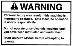
5 Safety Owner s Responsibilities The owner is responsible for the safe operation of this product. The important safeguards and instructions appearing in this manual are not meant to cover all possible conditions and situations that may occur. Common sense and caution are factors that cannot be built into any product. These factors must be supplied by the person(s) caring for and operating the product. The owner s responsibility is to: 1. Read and understand these instructions. 2. Operate the machine according to prescribed limitations. 3. Properly train others who may be permitted to operate the machine. 4. Heed the rules of safety, including but not limited to those in these instructions. 5. Exercise good judgment relating to safe operation and safe conduct by operators and spectators whether invited or not. 6. Always bring the safety decals and placards on the machine to the attention of operators and spectators. 7. Keep all shields and guards in place! Read and Heed The Special Messages! This safety alert symbol is used to indicate messages related to safety. When you see this safety symbol, obey the safety message to avoid personal injury, property damage, or both. A Caution message in this manual or on a machine placard means that you could be injured and/or equipment or property may be damaged if you do not follow instructions. A Warning message in this manual or on a machine placard means that a hazard exists that could result in severe personal injury or death. A Danger message in this manual or on a machine placard means that a hazard exists that will result in severe personal injury or death. 6


6 --Safety-- Location of Safety Messages 7


7 --Safety-- Learn to Be A Safe Operator Read This Manual. Know the controls on the Water-Reel and also how to stop the supply pump! Do not allow children to operate the Water-Reel. Do not allow anyone to operate the equipment without proper instruction. Protect Children Keep children away when you operate the Water-Reel. Do not allow children to operate the tractor that is positioning the Water-Reel. Never allow children to climb or ride on the machine at any time. Use Caution Around Pressurized Lines Be sure pressure is relieved from the supply line when disconnecting. If the sprinkler plugs, there may be pressure trapped in the Water- Reel tube. Stay Away From Operating Sprinklers Stay away and keep others away from the sprinkler head during operation. Pressurized fluid from a sprinkler can inflict serious injury to by-standers. 8


8 --Safety-- Use Caution When Towing Your Water-Reel is not intended for highway towing. Towing Speed: 12 MPH maximum on smooth surfaces. 3 MPH maximum on rough surfaces. Never tow the Water-Reel in excess of 12 MPH. Keep Hands and Clothing Away Do not under any circumstances reach into the Water-Reel while it is in operation. Keep All Guards and Shields In Place Never Operate this Machine with Safety Guards Removed! Never Service or Make Adjustments While The Water-Reel Is Pressurized Shut the Pump off at the source before attempting to do any service, maintenance or adjustments. Lock out tag the pump shut-off. Stay Away From Power Lines Avoid letting water contact power lines. Be careful not to contact power Lines with irrigation pipe or mechanical equipment. 9
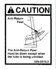
9 Controls Tongue Jack 2. Gear Selector (High-Low Range) behind door 3. Compensation/Shut off Bar 4. Anti-Return Pawl 5. Turntable Lock Pin 6. Neutral Gear Selector Rod 7. Two Step Pulley Belt Tensioner 8. Ground Speed Indicator 9. Stabilizer Leg Crank Handle (Models without hydraulics) 10. Cart Transport Lift Crank Handle (Models without hydraulics) 11. PTO Shaft Attachment Point (Behind Plastic shield) 12. Power Train Disengage Lever Note: These controls are the same for turbine or engine drive systems. Other controls for the specific drive types are shown in the Start-up & Operation section of this manual. 10
10 Handling The Polyethylene Tube The polyethylene irrigation tube is a durable product that will operate reliably for many years if handled properly and given a reasonable amount of care. Unlike rubber hose or hose with a woven jacket (lay flat hose), polyethylene is a semiridged product that retains its shape when it is not pressurized. This characteristic makes it feasible to pump fluid through it while it is rolled up on a reel. A few simple precautions need to be observed to prevent damaging the tube when operating your Water-Reel. When starting a new Water-Reel for the first time, you must pull the tube all the way out in order to correctly tighten the new tube on the spool. 1. Never transport the Water-Reel with the anti-return pawl disengaged! The tubing will become loose and tangled. Do not attempt to operate if there are any coils of tube that are loose or misplaced. If loose coils of tube are noticed after pulling the tube out, they must be tightened up by rotating the spool with the hand crank. If this is not possible then pull all of the tube out before attempting to rewind the tube. 2. Never try to move or relocate the machine if the tube is not fully rewound onto the machine. 3. Never pull the tube off the machine other than by pulling on the sprinkler cart (straight out from the machine). 4. Never run over the tube with any kind of vehicle and avoid pinching or pulling the tube around objects. Never bend the tube sharper than 25 times the diameter of the tube. 5. Be careful when operating other equipment near the tube. Make sure the tube doesn t get gouged or punctured. 6. Avoid using the PTO or engine drive to rewind the tube when it is not pressurized. When the tube is not pressurized during rewind the tube will flatten and the rewind mechanism cannot function properly. Keep the tube pressurized when rewinding! Remember, polyethylene tube is semi-rigid and subject to being kinked. These precautions will reduce the possibility of kinking or damaging your tube. Throughout the irrigation industry the words tube and hose are used interchangeably in connection with hard-hose traveling irrigation machines. 11
11 Lubrication Lubrication Points Lubricate with grease every 100 hours of operation: 1. Drum Axle Bearings* 9. Sprinkler Cart Wheel 2. Stabilizer Legs Bearing (not shown) 3. Stabilizer Crank Bearings 10. Turntable Bearing 4. Final Drive Cog/Ring Gear 11. Tongue Jack 5. Level Wind Idler Bearing 12. Check oil level in gear box 6. Level Wind Drive Chain (Oil) (90 wt. gear oil) 7. Level Wind Guide Chain (Oil) 8. Level Wind Fork Slide *Apply grease until excess grease comes out of bearing. Lubricate with grease once each season: Pack bearings on main chassis wheels. Tire Pressures Inflate tires to the pressure imprinted on each tire wall. 12
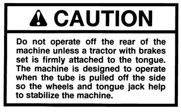
12 Start Up & Operation Tongue Jack The Ag-Rain Water-Reel models have as standard either a screw type or manual-hydraulic tongue jack. The tongue jack frame offers a set of 5 adjustment holes to augment the stroke of the screw by 11 inches. The stroke of the screw is 14 inches. See the diagram below. The dimensions apply to both types of jacks. Caution! Do not extend the screw-type tongue jack beyond the stroke of the screw. Extending the tongue jack beyond the stroke of the screw may cause damage to the tongue jack. Tongue Jack Adjustment Limits Start-Up Procedure Successful operation of the Water-Reel irrigation system depends a great deal on the operator s understanding of the proper pullout and start-up procedure. Unless you are an experienced operator of this type of equipment, do not attempt to operate this Water- Reel until you read and understand the preceding section titled Handling the Polyethylene Tube! The following steps are important. 1. Pull the Water-Reel to the area to be irrigated and safely secure the chassis. Rotate the spool so that the sprinkler cart is facing towards the path of irrigation and is approximately 90 degrees away from the chassis. Be especially careful to have the spool squarely aligned with the sprinkler cart travel path. 13
13 --Start Up-- Warning! Do not pull the tube off of the back of the machine. The stabilizer legs will not hold the load of incoming tube if the chassis wheels are not approximately 90 degrees from the sprinkler cart travel path. See diagram below. 2. Deploy the stabilizer legs. Manually or hydraulically extend the stabilizer legs until both stabilizer feet are firmly inserted into the ground. For hydraulic units, this will also lower the sprinkler cart. Warning! Never operate the Water-Reel with only one stabilizer leg in the ground. Never operate the Water-Reel without the stabilizer feet firmly inserted in the ground. Pulling the tube from the Water Reel 14

14 --Start Up-- 3. Disengage the drive by firmly pushing the disengage rod at rear of cabinet. Disengage Rod 4. Attach the water supply hose to the machine to confirm that all lines reach the Water-Reel and the Water-Reel is set in the proper place. Do not turn on the water. Be sure there are no kinks in the supply hose and that all gaskets are in place and in good condition. 5. Lower the sprinkler cart from its transport position (this was already completed for hydraulic sprinkler cart lifts). Set the desired sprinkler arc and confirm that the sprinkler is equipped with the proper nozzle. Note: Turbine drive irrigators have a minimum G.P.M. flow requirement. Do not attempt to operate at flows or pressures different from those listed on the Performance Guide placard that is installed on the machine! 6. Pull the sprinkler cart out the desired distance. If this is the first run, pull out the full length of the tube. It is important that the first run be a full length run so the tube becomes packed tightly on the reel. Note: If the tube is pulled out in an arc to follow a contour or to avoid an obstacle, the arc should be very gradual. Under no circumstances should the tube curve more than 90 degrees in its entire length. How well the tube will follow its laid out path back to the machine will depend mostly on the surface of the ground. For example, if there are contours or furrows to follow, the tube may track back very well. If the soil or vegetation is slippery and no rows or furrows exist, the tube may slide sideways across the laid out path and the sprinkler cart will be recoiled back to the machine in a straight line instead of following the intended arc. This will place an excessive side load on the level wind mechanism and may result in equipment failure or tube damage. 15

15 --Start Up-- Caution! If the tube is pulled out in an arc, the first 20% of the tube must be pulled straight away from the machine. Failure to observe this limitation places excessive side load on the level wind mechanism and may result in equipment failure or tube damage. See the section titled Handling The Polyethylene Tube. Use a gear in your tractor that will not exceed 3 MPH at full throttle. Pull the tube out at a steady rate and do not exceed 3 MPH. Do not start and stop. Slow the tractor to 1 MPH or less for fifty feet prior to stopping. The purpose of the gearbox brake is to prevent coils of tube from becoming loose on the tube spool. Loose coils of tube will make the level-wind mechanism appear to be out of time. In this case, the level-wind system will be damaged and a mis-wrap will occur. Coasting of the spool during the tube pull out is the most frequent cause of mis-wrap problems! This problem is most common when the Water-Reel is used often in short runs and the entire tube is seldom pulled all the way out or when the sprinkler cart is pulled out fast and with sudden stops. When the spool coasts, the irrigation tube will become loose on the spool. 7. Adjust sprinkler cart to the desired width. See Specification Section. 8. Turn on the pump. Do not pick up or hold Supply Hose as it is being pressurized! Confirm the sprinkler is operating as expected and in the desired arc. The arc of the sprinkler will affect the precipitation application of the system. Note the Precip Rate column on the performance guide located on the Water-Reel. The lowest precipitation rate will occur when the sprinkler is operating a full 360-degree circle. See below. Note: The swivel seal at the main bearing may leak initially at low pressure however will stop as pressure increases, and the o ring seats. Note: Arc settings where the sprinkler never throws water forward of the sprinkler cart could make the sprinkler cart track off line. This is caused by the continuous thrust of the sprinkler that tries to push the tube towards the Water-Reel. It is necessary to have some sprinkler thrust which puts the Tube under tension. Sprinkler Arc Limits 16
16 --Start Up-- 9. After all air is purged from the system and the sprinkler is operating smoothly, you can start the drive system if you have an engine drive. For turbine drives, allow the water to go through the system for several minutes to carry out any trash or debris that may have been in the mainline pipe. After the system is thoroughly flushed, start the drive system. Warning! Before starting the machine, exercise the compensation/ shut-off bar to confirm that the engine and/or turbine are stopped when the sprinkler cart reaches the machine. This confirms that the engine shut-off switch and/or turbine gate are properly adjusted and working. Always exercise the compensation/shut-off bar each time before the unit is restarted to confirm proper operation. Do not allow the machine to operate if the shut-off system is not working properly. Damage will result if the machine fails to stop when the irrigation tube is completely rewound. Caution! Do not engage or disengage the gearbox under high loads. Engaging or disengaging the gearbox under high loads may damage the gear train. 10. Important: Before Leaving the machine, exercise the compensation/shut-off bar that stops the engine or turbine. Confirm that it works easily and that it safely stops the turbine or engine. 11. Observe pressure, travel speed, and sprinkler operation. See the Specification section of this manual for performance information and then adjust speed to the desired travel rate. 12.When the sprinkler cart completes the irrigation run and has contacted the compensation/shut-off bar, the retraction of the tube will stop. With the irrigation run completed, stop the pump, lift the sprinkler cart into transport position, retract the stabilizer legs, and disconnect the supply hose, and rotate the spool and cradle to the transport position. The Water-Reel is now ready to be moved and set up in a new location. 13. If you are using the PTO rewind, avoid collapsing the tube by maintaining the operational water pressure during the entire PTO rewind. The tube may collapse if you are using the PTO rewind and do not have the proper water pressure. See the section titled Handling the Polyethylene Tube. Warning! When using the PTO rewind, the compensation/shut-off bar will not stop the machine! The operator must manually stop the rewind process. Failure to stop the rewind process while using PTO rewind will result in serious machine damage! 17

17 --Start Up-- Depth of Water Applied The depth of water applied by the Water-Reel is regulated by the speed of the sprinkler moving across the ground and the rate of water being discharged by the sprinkler head. The sprinkler nozzle size and the water pressure at the sprinkler determine the rate of water discharged. The selection of the sprinkler nozzle is made based on the water supply and pump performance. Travel Speed Settings Turbine Engine
18 --Start Up-- After the desired depth of water has been determined and the proper nozzle has been installed, follow the steps in the following example to set the speed: (Assume: 1.46 ring nozzle, 120 psi inlet pressure, and a desired depth of water of 1 inch.) 1. Find the proper section in the performance Guide for the 1.46 ring nozzle. (1) 2. Locate the 122-psi inlet pressure. (2) 3. Find depth of application 1.00 inch. (3) 4. Locate 111 feet per hour. (4) 5. The water pressure on the sprinkler nozzle is 70 psi. The flow in gallons per minute being discharged through the sprinkler is 355 and the wetted diameter is 385 feet. (5) 6. The effective irrigated width is 270 feet and the maximum effective irrigated length is 1455 feet. (6) 7. You can also note the precipitation rate (the rate that water is being applied to the soil) is 0.40 inches per hour. This computation is based on a 320-degree arc of the sprinkler with the arc symmetrical to the direction of travel. See sprinkler arc setting in this section. (7) 8. Hours required for a complete run about 13.2 can be read from the chart at the bottom of the performance guide entitled Retraction Speed of Irrigation Tube (Ft/Hr). (8) Note: This information is based on standard lengths of tube for the various models. Any tube of a non-standard length or diameter will substantially charge the performance. Consult the factory for performance information on non-standard tubes. Speed Compensation Speed compensation is necessary for uniform application of water. The build up of tube on the spool gives the spool a larger effective circumference. With a constant speed of rotation, each layer of tube on the spool makes a significant increase in the rate of sprinkler cart retraction speed during the irrigation run. From the beginning of the irrigation run to the end of the run the typical speed increase of a hard-hose traveler is about 40%. This means that without speed compensation, if you set the travel speed to apply 1 inch of water at the beginning of the run, you will get only 0.6 inches at the end of the run. On the average, the depth is only 0.8 inches. This level of uniformity is unacceptable in most cases. 19
19 --Start Up-- To better manage the uniformity of application, the Water-Reels are equipped with a speed compensator. The compensator slows the rotation of the spool at approximately the same rate that the tube builds up on the spool so the velocity of the incoming tube stays relatively constant throughout the irrigation cycle. The compensation system monitors the diameter of the spool by use of a bar that rides on the tube and slows the drive system to offset the increase in the circumference of the spool. The bar is attached mechanically to the turbine motor or to the throttle of an engine drive system. For Cruise Control equipped machines, the Cruise Control electronically compensates the rotation of the spool. The Cruise Control knows the size of the Water-Reel it is controlling and knows how much tube is on the spool. It then calculates the diameter of the spool and adjusts the rotational speed accordingly. The bar that rides on the tube is not used for speed compensation. It is used for shut-off in the event of a mis-wrap or when the sprinkler cart reaches the machine. The compensator systems will maintain a reasonably constant sprinkler cart retraction speed throughout the run. See the Maintenance & Adjustments section in this manual for more information about adjusting the turbine or engine compensators. Travel Speed Indicator The travel speed indicator displays the ground speed of the sprinkler cart. The speed is shown in feet per hour. Cruise Control equipped models do not have a tachometer. The speed is read directly from the Cruise Control screen. A shaft on the back of the gearbox (which turns at a speed relative to the rotation of the spool) drives the indicator. To make full use of the information displayed on the speed tachometer the operator must understand the various lines and symbols on the dial. The following information and diagram in this manual will be helpful. You should read and understand the previous section about Speed Compensation before proceeding. During operation, with the compensator operating properly, the needle will move counter clockwise (indicating slower spool rotation) as the layers of tube build up on the spool. This movement is normal. The lines in the dial numbered 1 thru 5 represent layers of tube on the spool. No. 1 represents the first layer of tube on an empty spool. The radial lines (compensation lines) that go across tube layer lines represent the track of the needle during the run. 20

20 --Start Up-- Standard Tachometer Face 21
21 --Start Up-- Turbine Drive Speed Settings Select the proper turbine/gearbox v-belt pulley and gearbox range combination. Refer to the speed range chart for correct selection (page 17). Caution! The belt position must be used to prevent excessive pressure loss! The life expectancy of the turbine motor bearings and seal will be substantially shortened if the turbine is allowed to run faster than necessary. With water flowing through the system and the belt position selected, adjust the speed control crank until the desired speed is indicated on the travel speed indicator (see illustration). Cruise Control equipped models control the speed via the keypad. See the Cruise Control operators manual for complete instructions. Compensator bar Shut off slide stop Rear tube Shut off rod Safety bar Compensation adjustment slide Butterfly shaft lever Speed control crank Gearbox disengage knob Travel speed indicator (Tachometer) Gearbox disengage bolt Shut off bar 22
22 Engine Drive Engine vs. Turbine These Water-Reels are powered by a 4 HP gasoline engine driving the machine through a set of two-step pulley reductions and a two-speed gearbox that provides a wide speed range. Most engine powered Water-Reels have a travel speed range from 30 ft/hr to 400 ft/hr. They are speed compensated by the engine throttle. This generation of engine driven machines is especially economical to maintain and they operate on a very small amount of fuel. The engine used on these machines is the Honda GX-120. There is no information in this manual pertaining to the particular engine in use. Operating and service information on the engine is provided by the engine manufacturer and is packed separately with the Water-Reel engine drive machine. 23
23 --Engine Drive-- Setting the Travel Speed The following steps are required to set the desired travel speed. 1. Determine the travel speed required to apply the desired depth by referring to the Performance Guide decal located on the Water-Reel. 2. Select the proper speed range from the following Engine Drive Speed Range charts. Engine Drive Speed Range 3. Disengage the drive and pull out the irrigation tube (see previous section entitled Start-Up and Operation ). Start the flow of water. 4. With the gearbox in neutral, start the engine. Shift the gear selector to start the machine. Loosen the speed control knob and slide the throttle link handle until the desired speed is shown on the travel speed indicator. Retighten the speed control knob. See the illustrations on page 24 for the location of the controls. 5. As the machine progresses, the compensation/shut-off bar will move the throttle linkage and maintain the travel speed as the irrigation tube accumulates on the spool. Warning! Before starting the machine, exercise the compensation/shut-off bar to confirm that the engine stops when the sprinkler cart reaches the machine. This confirms that the engine shut-off switch is properly adjusted and working. Always exercise the shut-off bar each time before the unit is re-started to confirm proper operation. Do not allow the machine to operate if the shut-off system is not working properly. Damage will result if the machine fails to stop when the irrigation tube is completely rewound. Caution! Do not engage or disengage the gearbox under high loads. Engaging or disengaging the gearbox under high loads may damage the gear train. 24
.")
24 Engine Drive Speed Control Linkage --Engine Drive-- There is seldom any adjustment required to the speed control linkage unless a part has been removed, replaced or damaged. The engine should run at 3600 RPM with the control linkage at its maximum adjustment and with no compensation (tube on first layer). Compensator Adjustment There is seldom any adjustment required to the compensation linkage unless a part has been removed, replaced or damaged. This is set at the factory. To increase compensation during the irrigation run, raise the Compensation Adjustment Slide in the slot. To decrease the compensation during the irrigation run, lower the Compensation Adjustment Slide in the slot. Speed adjustment knob Compensation adjustment slide Exercising the Compensation bar and observing the speed change on the speed indicator will verify the correct degree of compensation. Engine Drive Shut-Off Switch Adjustment There is seldom any adjustment required to the speed control linkage unless a part has been removed, replaced or damaged. When adjusting the engine shut-off switch, the tube should be on its last layer (or the bar should be positioned) as shown page Position the bar as if it was on its last layer, the switch ramp should already be in contact with the wobble switch. The wobble switch should just be on the verge of clicking. When the switch clicks, it grounds the engine ignition. Wobble Switch Shut off rod Switch ramp Switch mount 25
25 --Engine Drive-- 2. To ensure that the engine will not run after the irrigation cycle is complete, make sure the wobble switch clicks before the gearbox is shifted into neutral. Once the gearbox is in neutral the sprinkler cart will not advance the compensation/shut off bar and the engine grounding switch will be unable to ground the ignition system. The engine will continue to run. As the sprinkler cart comes into the machine, the sequence of events is as follows: a. The sprinkler cart will contact the shut-off bar. b. The shut-off rod and switch ramp will trip the wobble switch. Warning! Ensure that the switch ramp will trip the wobble switch before the shut-off bar has reached the level wind frame. If the shut-off bar is allowed to reach the levelwind frame before engine shut down or before the gearbox has been shifted to neutral, machine damage will occur. Safety Shut Off Adjustment Turbine and Engine The safety or secondary shut down feature is accomplished by the disengagement of the gearbox by the shut off bar 1. Adjust the actuator bolt on the lower left of the compensator/shut off bar so it disengages the gearbox just as the shut off bar contacts the level wind frame. 2. In normal operation the engine or turbine are shut off with the first movement of the shut off bar however if those systems fail the safety system stops the drive, preventing damage to the machine and/or sprinkler cart. 26

26 Hydraulic Controls Hydraulic controls are standard on the 3.7-inch chassis (T/E37A/1220) and larger models. On smaller sizes hydraulic controls are optional. The stabilizer legs and sprinkler cart lift are linked together mechanically so the hydraulic cylinders move both the stabilizer legs and the sprinkler cart lift at the same time. The tractor that tows the Water-Reel typically provides hydraulic power for the Water-Reel. The control valve on the tractor controls the lifting and lowering of the legs and sprinkler cart. 40A1320 Water-Reel With Hydraulic Controls 27
27 --Hydraulic Controls-- Caution! The operator should understand the hydraulic functions before attempting to operate the hydraulic controls. Operate the tractor or hydraulic power source at low engine speeds when using the Water- Reel hydraulics. Stabilizer Legs and Sprinkler Cart Lift 1. Pull the machine into position at the beginning of the irrigation run. Rotate the turntable and align the spool with the travel path. Adjust position and alignment if needed. Warning! Do not pull the tube off of the back of the machine. The stabilizer legs will not hold the load of incoming tube if the chassis wheels are not approximately 90 degrees from the sprinkler cart travel path. Please read the section entitled Start- Up and Operation. 2. Extend the tongue jack to accept the weight of the machine from the tractor drawbar and unhitch the tractor from the machine. If the hydraulic hoses have been connected to the tractor do not yet disconnect them. By using the tractor s hydraulic control valve, extend the hydraulic cylinders on the stabilizer legs until they are firmly planted in the ground, (wheels slightly of the ground). The stabilizer leg cylinders also control the sprinkler cart lift linkage. The sprinkler cart will be lowered when the legs are inserted in the ground. Warning! Never operate the Water-Reel with only one stabilizer leg in the ground. Never operate the Water-Reel without the stabilizer feet firmly inserted in the ground. 3. Turn off the hydraulic power, remove the hydraulic lines and unhook the chains from the sprinkler cart. See the section entitled Start-Up and Operation to begin irrigation cycle. 28

28 Maintenance & Adjustments Danger! All power sources including water pumps must be disconnected and secured before performing any maintenance or adjustments on your water-reel. Failure to disconnect all power sources before performing maintenance or adjustments may result in machine damage, personal injury, or death. Runner Clearance: The clearance between the runner vanes and the volute wear ring is set at the factory at which is satisfactory for most irrigation applications and normally should not be changed. If runner adjustment becomes necessary: A. Remove the faceplate, by removing eight 3/8 nuts from the bolt circle B. Remove the 5/8 runner lock nut. C. The runner is adjusted on the shaft by adding and removing spacers on the backside of the runner. The 5/8 runner lock nut must be replaced with a torque of 75 ft. lbs each time the spacers are added or removed. First adjust the runner on the shaft (with the faceplate held in place and without o-ring) until a slight metal to metal contact is heard as the runner is turned. This establishes a zero clearance point. To set the clearance to for clean water, remove one spacer on the runner shaft. Replace the 5/8 runner lock nut and torque to 75 ft. lbs. Caution Excessive runner clearance decreases turbine power capability of the water motor. D. Replace the faceplate o-ring and 3/8 nuts. Volute clearance Lock Nut Spacers Mechanical Seal Bearing Runner Runner Shaft Faceplate 29
29 --Maintenance & Adjustments-- Turbine Shut Off Adjustment The turbine shut off slide stop see page 21 has been adjusted at the factory, however if it has been disassembled, or changed and adjustment becomes necessary. 1. Hold the shut off bar fully down against the level wind frame (See page 21). 2. Pull the butterfly shaft lever to its extreme open position (mark on shaft end parallel with turbine body, see illustration below on this page). 3. Move the shut off slide stop against the rear tube of the shut off rod, and tighten both set screws (See page 21). 4. Exercise shut off bar to be sure that when it is depressed fully, the butterfly shaft lever is latched in the open position. Butterfly shaft lever Turbine body Mark 30
30 --Maintenance & Adjustments-- Level Wind Timing Proper timing of the levelwind mechanism is essential for the successful operation of the Water-Reel. Improper levelwind timing will result in mis-wrapped tube. Travel will be interrupted because the auto compensation/shut-off bar will stop the drive system in order to prevent damage to the irrigation tube. Levelwind timing is set at the factory and normally does not need adjusting unless a part has been removed, replaced or damaged Warning! Do not continue to operate if the tube is not winding properly! Operation of a machine that is not winding properly may result in machine damage or personal injury. IMPORTANT! If the machine levelwind appears to be malfunctioning, be positive that the levelwind timing is really at fault before attempting to change the timing. This machine was shipped from the factory with the tube wound on it. The levelwind timing was set at the factory prior to installing the tube. If the levelwind mechanism has not been disassembled or the tube has not been removed & reinstalled, it is very unlikely that the timing is wrong. If the tubing is loose on the spool the levelwind system will appear to be out of time. See the section titled Water-Reel Start-up & Operation. Level Wind Timing To re-time the levelwind, these steps must be followed: 1. Pull all the irrigation tube out from the Water-Reel. The elbow to which the tube is fastened must be 45 degrees behind the axle centerline on the bottom of the spool (See diagram). Be especially careful not to pull the tube off the elbow. 31
31 --Maintenance and Adjustment-- Caution! Never attempt to retime the Water-Reel without first pulling all the tube out. Changing the timing with some of the tube still on the spool may result in damage to the irrigation tube and/or the Water-Reel. 2. Observe the position of the levelwind carrier drive lug on the horizontal levelwind chain. (The chain that runs left to right just behind of the compensation bar). The drive lug must be in its most extreme position (half way around the sprocket and on the same side of the Water-Reel as the spool elbow. (See diagram). 3. To change the timing, remove the shield and the cap screws from the levelwind input sprocket. Rotate the hub of the gearbox shaft until the drive lug is positioned as described in step #2. Re-install the cap screws in the new position. Reinstall the levelwind drive chain shield. Gear Box Neutral-Shift and Handle The gearbox must be shifted to neutral prior to tube pull out, and re-engaged at the beginning of the irrigation run. Drive Roller Adjustment If the drive system has been disassembled, it will be necessary to adjust the mesh of the ring gear teeth to the gearbox drive roller. The ring gear is a large part that will not be perfectly concentric. Tape or fix a felt tip marker to a frame member and rotate the drum with the marker touching the outside face of the main gear. This will mark the point in which the ring gear teeth are closest to the drive roller. Rotate to this point on the ring gear so it is exactly at the drive roller. The clearance is adjusted by moving the clamps that fasten the gearbox mount to the frame of the Water-Reel. Lower the gearbox until the drive roller just contacts the crotch of the teeth of the ring gear, then tighten the gearbox mounting bolts. A scissor jack is ideal for raising & lowering the gearbox. Rotate the spool to be sure the roller to ring gear setting is correct with no interference. Pinion drive roller Point on ring gear that is closest to pinion drive rollers Ring gear 32
32 --Maintenance & Adjustment-- Sprinkler Cart Lift The sprinkler cart lift uses a cable winch or a hydraulically powered frame for transport. The only adjustment required is to locate the lift points (cable winch or chain attachments) from side to side. The lift points should be exactly in line with the sprinkler cart at the end of the run. Because the tube wraps differently when it is pressurized and full of water, it is not possible to locate the lift adjustment points until after the first operation of a new machine. Lift frame height adjustment is made by raising or lowering pins in frame posts. Sprinkler Cart The sprinkler carts used on the Ag-Rain Water-Reels are designed to operate in row crops with the crop height somewhat taller than the underside clearance on standard row-crop tractors that might be used to pull the tube out. For best performance it is desirable to keep the sprinkler height as low as possible. There are two important reasons. First, the stability of the cart is less affected by the thrust of the sprinkler. Second, wind has considerably less effect on the performance of the sprinkler. See the section titled Specifications. Warning! Keep all persons away from operating sprinklers! Contact an operating sprinkler may result in personal injury or death. The sprinkler carts have adjustable width rear axles. The rear axle should be adjusted to the maximum width compatible with the crop being irrigated for best stability. For adverse conditions such as hillsides, extra high flow, or high pressure, ballast may be required to prevent the cart from tipping over. Additional ballast can be obtained by filling the rear tires with fluid. The sprinkler cart has been adjusted to track straight from the factory. Tracking can be adjusted by adjusting the angle of the front wheel is via slotted and oversized holes. To assure straight tracking, take the cart to a concrete floor and push 50 feet down a chalk line to confirm tracking in a straight direction. Tracking be corrected by trial and error in the field. If the cart does not track in a straight direction the tube end will appear as though it has a bend in it. This is not the case. Cutting the end off the tube will not solve the tracking problem. Study the chart regarding sprinkler cart specifications in the section titled Specifications before adding riser pipe extensions or adjusting the wheel track width. The chart shows the height of the water stream at 5 foot and 10 foot distances from the riser pipe. Be sure to consider the trajectory of the sprinkler when determining the sprinkler height and keep the sprinkler as low as possible. 33
33 --Maintenance & Adjustment-- Rewind Speed Compensation Adjustment The compensation adjustment is normally set from the factory. 1. Place the compensator rod bolt midway in its slot on the compensator/shut off bar. 2. Set the desired rewind speed at the beginning of the run with the speed control crank. 3. As the sprinkler cart nears the end of the run (approximately 100 ft.) adjust the compensator rod bolt in its slot to achieve the beginning of the run re-wind speed. A. Move bolt and rod up in its slot to increase compensation (reduce rewind speed) B. Move bolt and rod down in its slot to decrease compensation (increase rewind speed) Shut-off bar Speed control crank Compensator rod bolt 34
34 --Maintenance & Adjustment-- Installing Polyethylene Tube Fittings Danger! Installing fittings or repairing polyethylene tube used on your Water-Reel is hazardous! The tube has a shape memory from being coiled on a reel and will coil back with great force as the tube is released from one end or severed. This condition poses a serious hazard to personnel and/or property. The tube must be properly restrained anytime the tube or the tube fittings are being repaired or replaced. The fittings used on the ends of the polyethylene tube are made to screw into the tube much the same way as a field repair of a hydraulic hose. A threaded insert screws into the inside of the tube while an outer sleeve keeps the tube from enlarging as the insert is installed. This provides a watertight seal and a secure grip on the tube for dragging. Cutaway of Installed Sprinkler Cart Fitting The following steps should be followed when installing fittings: 1. Secure the end of the tube by fastening it to a tractor or other heavy object. Cut the tube. Make sure the cut on the end of the tube is square. 2. Chamfer the inside of the tube by using a sharp knife, wood rasp or a reamer. Reamers are available for tubes 2.5 inch I.D. through 4.5 inch I.D. Your dealer may have a reamer that you may rent or buy. The tube should be chamfered evenly until approximately ¼ of the threaded portion of the fitting can be freely pushed into the tube by hand without turning. 3. Before putting the sleeve on the outside of the tube, screw the threaded portion of the fitting into the tube. Take care to keep the fitting and the tube aligned while threading. This process cuts a partial thread in the tube which makes it easier to keep the fitting straight during the final installation. Remove the fitting. 35
35 --Maintenance & Adjustment-- 4. Now place the sleeve on the tube and push it on until it is flush with the cut end of the tube. 5. Apply lubricant to the fitting and to the inside of the tube. The best lubricant is liquid dishwasher soap. Now screw the fitting in until all the threads are in the tube. Again, take care to keep the fitting straight. 6. Reach inside the coupling and remove any shreds of polyethylene created as a result of cutting the thread in the tube. These may foul the sprinkler. Tools used during installation depend on which fitting is being installed. To install a flangestyle fitting, use bar 5 or 6 feet long placed between two bolts inserted through the holes in the flange. For the spool elbow, use a pipe and/or a large pipe wrench. For fittings with drive lugs inside the fitting, a special installation tool is required. This tool is not provided with the fittings. Fittings that Require a Driver The following diagram shows a typical driver for these fittings. The blade of the driver is made from 3/8 x 4 plate. The width of the blade is the same or slightly less than the diameter of the fitting. Weld the blade to a heavy steel bar or 1 schedule 80 water pipe approximately 48 long. Typical Driver Tool 36
36 --Maintenance & Adjustment-- Screw-in Tube Menders Screw-in menders must be installed with the Driver Tool. The menders are joined with a threaded collar much the same as a typical pipe union. See following diagram. Fusion Butt Welding Screw-in Mender Another way to repair a polyethylene tube that is in good condition is by fusion welding. This method requires special welding equipment and will return the tube back to its original condition if done properly. Tubes that are old or badly worn may be difficult or impossible to weld. Caution! Tube must cure at least 12 hours after welding. The tube may separate if it is not allowed to cure properly. Machine damage or personal injury may occur if the tube suddenly separates. To have the tube fusion welded, contact your Kifco dealer or call Kifco, Inc. and ask for customer service. 37
37 --Maintenance & Adjustment-- Winterizing and Storage Winterizing 1. Be certain that the drain valve or pipe plug on the sprinkler cart body is open and the sprinkler cart is lowered from the sprinkler cart lift so that all water is drained from the sprinkler cart. Disconnect the sprinkler cart from the end of the irrigation tube to be sure all of the water is out. 2. Be certain the water inlet to the Water-Reel is open and the water supply hose removed. Pull 1 or 2 coils of tube off the spool to expel some of the water from the spool axle and sprinkler cart fittings. Rewind the coils of tube by using the hand crank. 3. Freezing will not damage the polyethylene tube used on your Water-Reel! Pulling the tube all the way out to drain the water then rewinding with the PTO is not recommended! This process is not effective and exposes the system to damage. Please read the section titled Handling the Polyethylene Tube. Caution! Even though the polyethylene tube does not need to be drained, all the metal parts must be drained before the Machine is subjected to freezing temperatures. Failure to drain all The metal parts may result in machine damage. Storage 1. Refer to the section titled Lubrication and lubricate all points to prevent rust and corrosion from forming. 2. Store the Water-Reel away from the direct rays of the sun. 3. Make sure all openings such as the water inlet are plugged so rodents and insects cannot bring foreign material into the Water-Reel. 4. When taking the Water-Reel out of storage, be sure there are no rodent or insect nests inside the tube end of the Water-Reel. 5. For engine driven machines, service the engine in preparation for the next season. 38
38 Assembly Water-Reels are usually shipped with the primary assembly complete. The only items to assemble at the destination are: 1. Wheels. Make sure all lug bolts and axle adjustment bolts are tight. They must be rechecked after being towed one mile. 2. Sprinkler Cart. Attach the sprinkler cart to the tube end. 3. Sprinkler. Install on the sprinkler cart riser pipe. 4. Sprinkler Nozzle. Install the appropriate sprinkler nozzle. 5. Sprinkler Cart Lift Arm. Install the sprinkler cart transport lift arm on Water-Reels equipped with the single arm lift. Final adjustment of the sprinkler cart lift assembly should be made upon completion of the first irrigation run. The lift hooks should be located directly above the sprinkler cart when the sprinkler cart is completely drawn up to the compensation/shut-off bar. This exact location is not possible before the Water-Reel has been operated because the irrigation tube may be loose on new units, particularly if they have been shipped a long distance. 39
 1629 1166 864 515 Hitch Wt. W/Cart (Wet) 4582* 3268 2517 1470 Speed Range Ft/Hr. (Engine) 40-400 40-400 40-400 40-400 Speed Range Ft/Hr.")
39 Specifications Machine Dimensions Model: E/T40A E/T37A E/T33A E/T30A PE Tube I.D. (In.) Dry Weight (lbs.) Weight W/Water (lbs.) Hitch Wt. W/Cart (Dry) Hitch Wt. W/Cart (Wet) 4582* Speed Range Ft/Hr. (Engine) Speed Range Ft/Hr. (Turbine) Tire Size 11L x 15 11L x 15 11L x 15 11L x 15 Dimensions: (ft-in.) A B C 8-4/ / / /7-0 D E *Note: The E/T40A hitch weight assuming front axle off the ground. Operational tongue weight will be less. 40
40 --Specifications-- Sprinkler Carts Models Dim. Description E/T40A E/T37A E/T33A E/T30A (A) Wheel Track Minimum (B) Wheel Track Maximum (C) Crop Clearance (D) Sprinkler Base Height (E) Nozzle Height (F) Trajectory (Degrees) (G) Stream Height. 5 Feet (H) Stream Height. 10 Feet The above information is based on the sprinklers supplied as standard by Kifco, Inc. If a different sprinkler is being used this information may not be correct. The Stream Heights are to the centerline of the system. All dimensions are approximate! 41
41 --Specifications-- Sprinkler Cart Configurations Sprinkler Cart Configuration Limits The sprinkler cart can be adjusted in many of different configurations. The cart can be symmetric or asymmetric. The above diagram shows the limits of the configurations. All dimensions are approximate! 42
42 Optional Equipment 1. High Pressure Shut-Off System. This system is designed to send high backpressure to the pump when the sprinkler cart reaches the Water-Reel compensation/shut-off bar. The pump must be equipped with a high-pressure shut-off switch. The valve contains a slow-closing diaphragm that gradually increases the pressure on the pump. This device requires a supply pump with a performance curve that will provide the appropriate pressure rise to activate the high-pressure shut-off pump switch (not included with this kit). Also the pipeline to the Water-Reel must have a pressure rating high enough to tolerate the total pump head. Notice: Kifco, Inc. accepts no responsibility for any consequential damage resulting from improper installation or operation of this device. 2. Low Pressure Engine Drive Shut-off. This gauge is used to stop the engine driven Water-Reel if the supply pump stops. It consists of a Murphy Switch gauge and wire capable of grounding the engine ignition circuit if the machine inlet pressure falls below a predetermined level. 3. Cruise Control. Kifco s electronic speed control offers state-of-the-art speed management as well as delayed start. Information such as time to completion and length of tube remaining is also displayed. 4. Riser Pipe Extensions. Extensions for elevating the sprinkler on the sprinkler cart are available. They are available in one and two foot lengths. 5. Filter Cone. Filter cones should be used on all turbine driven Water-Reels used for slurry and irrigation operations where foreign objects such as rocks are known to be present. The stainless steel cone inserts into the supply hose at the inlet of the machine. Available in three or four inch diameters (must match inlet size). 6. Hydraulic Stabilizer Legs/Sprinkler Cart Lift. Hydraulic stabilizer leg and sprinkler cart lifts are available on all the new AG-Series models. 7. Hydraulic Turntable/Tongue Jack. Hydraulic turntable and jack are available as an option for T/E30 and T/E33 this feature is standard on 37T/E and 40T/E models. 8. Crossover Pipes. If your application must feed the water from the opposite side of the machine, Kifco sells crossover pipes for all the new AG-Series models. 9. Booster Pump. The 30A980 and 33A1120 have 18hp booster pumps available if your application demands higher pressure at the sprinkler. See your dealer for information. 10. Engine Drives. All the new AG-Series have engine drive kits available. These kits can be factory installed or ordered later to retrofit your machine. 11. Sprinkler Options. Kifco offers several choices in large sprinklers for their Water- Reels. 43
OPERATOR S MANUAL. 700 South Schrader Avenue P.O. Box 290 Havana, IL Phone (309) Fax (309)
 Fax (309)") OPERATOR S MANUAL Models Turbine & Engine Drive 30 x 980 30x1220 33x1120 37x1080 37x1220 40x1250 40x1320 45x1150 Chassis Sizes ST4 - ST5 - ST6 - ST7 700 South Schrader Avenue P.O. Box 290 Havana, IL 62644
OPERATOR S MANUAL Models Turbine & Engine Drive 30 x 980 30x1220 33x1120 37x1080 37x1220 40x1250 40x1320 45x1150 Chassis Sizes ST4 - ST5 - ST6 - ST7 700 South Schrader Avenue P.O. Box 290 Havana, IL 62644
OPERATOR S MANUAL. 700 South Schrader Avenue P.O. Box 290 Havana, IL Phone (309) Fax (309)
 Fax (309)") OPERATOR S MANUAL Models Turbine & Engine Drive 27 x 980 30x660 Chassis Sizes ST3 700 South Schrader Avenue P.O. Box 290 Havana, IL 62644 Phone (309)543-4425 Fax (309)543-4945 www.kifco.com Introduction
OPERATOR S MANUAL Models Turbine & Engine Drive 27 x 980 30x660 Chassis Sizes ST3 700 South Schrader Avenue P.O. Box 290 Havana, IL 62644 Phone (309)543-4425 Fax (309)543-4945 www.kifco.com Introduction
OPERATOR S MANUAL. Models. T30A to T40A E30A to E40A
 Ag-rain OPERATOR S MANUAL Models T30A to T40A E30A to E40A Copyright February 2003 by Kifco Inc. Kifco Inc. 707 South Schrader Avenue, P.O. Box 290, Havana, IL 62644 Phone 309/543-4425 Fax 309/543-4945
OPERATOR S MANUAL. 700 South Schrader Avenue P.O. Box 290 Havana, IL Phone (309) Fax (309)
 Fax (309)") OPERATOR S MANUAL Models Turbine & Engine Drive 30 x 980 30x1220 33x1120 37x1080 37x1220 40x1250 40x1320 45x1150 Chassis Sizes ST4 - ST5 - ST6 - ST7 700 South Schrader Avenue P.O. Box 290 Havana, IL 62644
OPERATOR S MANUAL Models Turbine & Engine Drive 30 x 980 30x1220 33x1120 37x1080 37x1220 40x1250 40x1320 45x1150 Chassis Sizes ST4 - ST5 - ST6 - ST7 700 South Schrader Avenue P.O. Box 290 Havana, IL 62644
Thank you for purchasing a Nelson RainTrain2.
 Thank you for purchasing a Nelson RainTrain2. Read this manual carefully to learn how to operate and service your machine properly. Failure to do so can result in personal injury and/or property damage.
Reel Rain Jr. Model T200Sx320 & T200Lx580
 Reel Rain Jr. Model T200Sx320 & T200Lx580 Beginning Serial # 430000 1st Edition, MAN086 March 1, 2005 Owner's Name Dealer's Name Serial Number Date Purchased Model No. Introduction Thank You for purchasing
Reel Rain Traveler Irrigation B1025, 1030
 Reel Rain Traveler Irrigation B1025, 1030 3rd Edition, Serial # 370600 April 2005 MAN081 2005 Reel Rain Traveler Irrigation Series B1025 and B1030 are manufactured by Amadas Industries: You can find us
610 BUSHEL MANURE SPREADER
 610 BUSHEL MANURE SPREADER RODA MANUFACTURING 1008 LOCUST ST. HULL, IA. 51239 Art s-way Manufacturing 712-439-2366 Co., Inc. Hwy 9 West - PO Box 288 WWW.RODAMFG.COM Armstrong, IA. 50514 U.S.A 2 INTRODUCTION
Instruction Manual for Operation & Maintenance
 Instruction Manual for Operation & Maintenance BigSprinkler.com 15250 Sunshine Rd. Yukon, OK. 73099 1-855-805-7901 Introduction Thank you for purchasing a ReelGreen RG25 Traveling Sprinkler System. Please
ReelGreen RG20 Instruction Manual For Operation and Maintenance
 ReelGreen RG20 Instruction Manual For Operation and Maintenance BigSprinkler.com 15250 Sunshine Rd. Yukon, OK. 73099 800-373-9325 Introduction Thank you for purchasing a ReelGreen RG20 traveling sprinkler
MMR20. Instruction Manual for Operation & Maintenance. IB International. Ph:
 MMR20 Instruction Manual for Operation & Maintenance IB International www.ibinternational.com.au Ph: 07 3399 1288 Contents Introduction... 2 Identification Data... 2 Machine Controls & Components... 3
Caution. Do not operate your Micro Rain traveler without a serious overview of this manual. Keep children and unauthorized people away from traveler
 Thank you for purchasing a Micro Rain MR25 traveling sprinkler system. Please read this manual carefully before operation in order to become familiar with all components and their function. Safety is the
37A- S/N 350,000 Up. Turbine Drive Water-Reels. Engine Drive Slurry-Reels T37A E37A. Parts Manual. Serial No. 350, ,999
 37A- S/N 350,000 Up Turbine Drive Water-Reels Engine Drive Slurry-Reels T37A E37A Parts Manual Serial No. 350,000-359,999 700 S. Schrader Ave. Havana, Illinois 62644 Phone: 309-543-4425 Fax: 309-543-4945
Do not operate your Micro Rain traveler without a serious overview of this manual. Keep children and unauthorized people away from traveler
 INTRODUCTION Thank you for buying a Micro Rain traveling sprinkler. Please read this manual carefully before assembling and operation in order to become familiar with it s many functions. Your safety is
25 BUSHEL MANURE SPREADER
 25 BUSHEL MANURE SPREADER RODA MANUFACTURING 338 MAIN ST. HULL, IA. 51239 Art s-way Manufacturing 712-439-2366 Co., Inc. Hwy 9 West - PO Box 288 WWW.RODAMFG.COM Armstrong, IA. 50514 U.S.A 2 INTRODUCTION
MR32 Instruction Manual For Operation & Maintenance
 MR32 Instruction Manual For Operation & Maintenance KID Group 15250 Sunshine Rd. Yukon, OK. 73099 800-373-9325 Introduction Thank you for purchasing a Micro Rain MR32 traveling sprinkler system. Please
4745 Drill OWNER'S MANUAL (06-08) #
 #") 4745 Drill OWNER'S MANUAL (06-08) # 605865 Identification Your CrustBuster drill is identified by a Serial Number and Model Number. Record these numbers in the spaces provided in this manual and refer
4745 Drill OWNER'S MANUAL (06-08) # 605865 Identification Your CrustBuster drill is identified by a Serial Number and Model Number. Record these numbers in the spaces provided in this manual and refer
Operator's Manual. VC-60 & VC-60 Plus Harper Industries, Inc. 7/03 Part No
 Operator's Manual VC-60 & VC-60 Plus 2003 Harper Industries, Inc. 7/03 Part No. 970066 Thank you for purchasing a Harper/Goossen Verti-Cutter. As with all Harper/Goossen products, the Harper/Goossen Verti-Cutter
tRIPr Chief Grain Cart. Operator s Manual. Operator s Manual
 125-000-01 125-000-01 1tRIPr 1tRIPr Operator s Manual 1210 Chief Grain Cart Operator s Manual Operator s Manual TO THE DEALER Predelivery/Delivery Checklist 1210 Grain Cart PREDELIVERY/DELIVERY CHECKLIST
AUTO REWIND AIR HOSE REEL
 Model #s 46845, 46848 AUTO REWIND AIR HOSE REEL OPERATOR S MANUAL STORE THIS MANUAL IN A SAFE PLACE FOR FUTURE REFERENCE!? NEED HELP? Save time, contact us first. 888-648-8665 support@tekton.com WARNING:
Turbine Drive Water-Reels. Engine Drive Slurry-Reels. T40M / T45M Squatter (MG1) Parts Manual. Serial No. 340,000 +
 Parts Manual. Serial No. 340,000 +") Turbine Drive Water-Reels Engine Drive Slurry-Reels T40M / T45M Squatter (MG1) Parts Manual Serial No. 340,000 + 700 S. Schrader Ave. Havana, Illinois 62644 Phone: 309-543-4425 Fax: 309-543-4945 Page 1
Turbine Drive Water-Reels Engine Drive Slurry-Reels T40M / T45M Squatter (MG1) Parts Manual Serial No. 340,000 + 700 S. Schrader Ave. Havana, Illinois 62644 Phone: 309-543-4425 Fax: 309-543-4945 Page 1
TABLE OF CONTENTS. Warranty Disclaimers Delivery Checklist After Sale Checklist Safety Set Up... 8
 TABLE OF CONTENTS Pickett Equipment Warranty... 2 Warranty Disclaimers... 3 Delivery Checklist... 4 After Sale Checklist... 4 Safety... 5-7 Set Up... 8 Machine Adjustments and Operation... 9 Maintenance
8th. Revision 37A- S/N 330,000 Up Jan. 01, Turbine Drive Water-Reels. Engine Drive Slurry-Reels T37A E37A. Parts Manual
 8th. Revision 37A- S/N 330,000 Up Jan. 01, 1998 Turbine Drive Water-Reels Engine Drive Slurry-Reels T37A E37A Parts Manual Serial No. 330,000-349,999 700 S. Schrader Ave. Havana, Illinois 62644 Phone:
SERIES A & AA ROLLER DOORS INSTALLATION GUIDE
 SERIES A & AA ROLLER DOORS INSTALLATION GUIDE THESE INSTRUCTIONS ARE PROVIDED FOR USE BY EXPERIENCED INSTALLERS OF GARAGE DOORS BY UNDER-TAKING THE INSTALLATION OF THIS DOOR, THE INSTALLER UNDERSTANDS
STOP. Broadcast Spreader. Operator's Manual. Model No Safety Assembly Operation Maintenance Parts
 Operator's Manual STOP Broadcast Spreader Model No. 486.2400 DO NOT RETURN TO STORE For Missing Parts or Assembly Questions Call 1-866-56-8388 CAUTION: Before using this product, read this manual and follow
57 ROUGH CUT OWNER S MANUAL. With Assembly Instructions For Model: MR55H KUNZ ENGINEERING, INC. / MENDOTA, IL / PH (815) /07
 /07") 57 ROUGH CUT OWNER S MANUAL With Assembly Instructions For Model: MR55H KUNZ ENGINEERING, INC. / MENDOTA, IL 61342 / PH (815) 539-6954 1/07 ASSEMBLY INSTRUCTIONS Read the complete assembly instructions
57 ROUGH CUT OWNER S MANUAL With Assembly Instructions For Model: MR55H KUNZ ENGINEERING, INC. / MENDOTA, IL 61342 / PH (815) 539-6954 1/07 ASSEMBLY INSTRUCTIONS Read the complete assembly instructions
MODEL NO & UP SAFETY INSTRUCTIONS. Keep this Operator s Manual in the plastic tube behind the operator seat.
 FORM NO. 94-7276 MODEL NO. 41026-60101 & UP OPERATOR S INSTRUCTIONS HOSE REEL KIT To assure maximum safety, optimum performance, and to gain knowledge of the product, it is essential that you or any other
Centrifugal PTO Pumps. 2 nd Edition
 Centrifugal PTO Pumps 2 nd Edition MAN072 November 2005 2005 Centrifugal PTO pumps are manufactured by AMADAS Industries. You can find us on the Web at: www.amadas.com or e-mail us at: amadas@amadas.com
Operating and Assembly Manual
 Model 1080 Operating and Assembly Manual Midwest Equipment Manufacturing, Inc. 5225 Serum Plant Road Thorntown, IN 46071 08-02-16 SAFETY RULES Remember, any power equipment can cause injury if operated
Wheel Horse. 44 Snowthrower. for 5xi Lawn and Garden Tractors. Model No & Up. Operator s Manual
 FORM NO. 8 Rev A Wheel Horse Snowthrower for 5xi Lawn and Garden Tractors Model No. 7966 890050 & Up Operator s Manual IMPORTANT: Read this manual, and your tractor manual, carefully. They contain information
Kit No Please read these instructions completely before proceeding with installation. Air Spring Kit Parts List. Bracket Attaching Hardware
 Kit No. 59532 MN-572 (021108) ECR 7136 Please read these instructions completely before proceeding with installation Air Spring Kit Parts List A Item Description Quantity A Air Sleeves 2 B Upper Brackets
MMR25. Instruction Manual for Operation & Maintenance. IB International. Ph:
 MMR25 Instruction Manual for Operation & Maintenance IB International www.ibinternational.com.au Ph: 07 3348 8300 Contents Introduction... 2 Identification Data... 3 Machine Controls & Components... 3
<THESE INSTRUCTIONS MUST BE GIVEN TO THE END USER> B&W
 B&W Trailer Hitches 6 Hawaii Rd / PO Box 86 Humboldt, KS 66748 P:60.473664 F:60.869.903 Turnoverball Gooseneck Hitch Installation Instructions MODEL 08
Operating and Assembly Manual
 Model 455-IC/PRO/H Operating and Assembly Manual Midwest Equipment Manufacturing, Inc. 5225 Serum Plant Road Thorntown, IN 46071 03-08-12 SAFETY RULES Remember, any power equipment can cause injury if
Model 858-RH. Operating and Assembly Manual. Palmor Products Inc Serum Plant Road Thorntown, IN 46071
 Model 5-RH Operating and Assembly Manual Palmor Products Inc. 55 Serum Plant Road Thorntown, IN 6071 3/31/015 SAFETY RULES Remember, any power equipment can cause injury if operated improperly or if the
BOLT-ON AND WELD-ON FLUSH FLOOR SLIDEOUT SYSTEMS OPERATION AND SERVICE MANUAL
 BOLT-ON AND WELD-ON FLUSH FLOOR SLIDEOUT SYSTEMS OPERATION AND SERVICE MANUAL TABLE OF CONTENTS SYSTEM...... Warning........ Description...... Prior to Operation OPERATION... Main Components... Mechanical...
CONTENTS: 5740AH - 40 Ton Air/Hydraulic Shop Press 5750AH - 50 Ton Air/Hydraulic Shop Press OWNER'S MANUAL
 OWNER'S MANUAL CONTENTS: Page 1 Specifications 2 Safety Information and Warranty Information 3 Parts List 4-6 Assembly Instructions 7 Pump and Ram Assembly Instructions 8 Procedure for Bleeding Air 9 Pump
Operating and Assembly Manual
 Model 455-IC/PRO/H Operating and Assembly Manual Palmor Products Inc. 5225 Serum Plant Road Thorntown, IN 46071 03-08-12 SAFETY RULES Remember, any power equipment can cause injury if operated improperly
Kit No Please read these instructions completely before proceeding with installation. Parts List G J I K L H CC FF DD MN-505 (01201) NPR 3733
 NPR 3733") Kit No. 57154 MN-505 (01201) NPR 3733 Please read these instructions completely before proceeding with installation Parts List by www.airliftcompany.com Item P/N Description Quantity A 58407 Air Spring
Kit No. 57154 MN-505 (01201) NPR 3733 Please read these instructions completely before proceeding with installation Parts List by www.airliftcompany.com Item P/N Description Quantity A 58407 Air Spring
Operating and Assembly Manual
 Model 470-/H/PRO/IC Operating and Assembly Manual Midwest Equipment Manufacturing, Inc. 5225 Serum Plant Road Thorntown, IN 46071 11-11-11 SAFETY RULES Remember, any power equipment can cause injury if
W & A 12 ROW TOP LEVELING STACKER LEVEL BANDER
 W & A 12 ROW TOP LEVELING STACKER LEVEL BANDER NO. 3640 OPERATOR S MANUAL TO THE OWNER: Congratulations on your purchase of a new W & A Top Leveling Stacker Level Bander. Your selection is an indication
57 ROUGH CUT OWNER S MANUAL. With Assembly Instructions For Models: MR55T, MR55B & MR55K
 57 ROUGH CUT MR55K MR55B OWNER S MANUAL With Assembly Instructions For Models: MR55T, MR55B & MR55K KUNZ ENGINEERING, INC. / MENDOTA, IL 61342 / PH (815) 539-6954 1/05 ASSEMBLY INSTRUCTIONS Read the complete
W & A 12 ROW TOP LEVELING STACKER LEVEL BANDER
 W & A 12 ROW TOP LEVELING STACKER LEVEL BANDER NO. 3640 OPERATOR S MANUAL TO THE OWNER: Congratulations on your purchase of a new W & A Top Leveling Stacker Level Bander. Your selection is an indication
CALIFORNIA TRIMMER MOWER MAINTENANCE MANUAL
 CALIFORNIA TRIMMER MOWER MAINTENANCE MANUAL 2 Table of Contents Section 1: General Information Page Handle Assembly Instructions 4 Maintenance All Models 6 Oil Change Procedures All Models 9 Height Adjustment
LEWIS WINDROWER OWNER / OPERATOR MANUAL
 LEWIS WINDROWER OWNER / OPERATOR MANUAL MODEL # WR-1 WINDROWER Manufactured by: LEWIS BROTHERS MANUFACTURING, INC. Post Office Box 146 Baxley, GA 31513 Tel: (912) 367-4651 Fax: (912) 367-3958 2-21-14 1
57 ROUGH CUT OWNER S MANUAL. With Assembly Instructions. For Models: MR55T, MR55B-17.5HP, MR55B-22HP & MR55K
 57 ROUGH CUT MR55K MR55B OWNER S MANUAL With Assembly Instructions For Models: MR55T, MR55B-17.5HP, MR55B-22HP & MR55K KUNZ ENGINEERING, INC. / MENDOTA, IL 61342 / PH (815) 539-6954 1/07 ASSEMBLY INSTRUCTIONS
OPERATOR S MANUAL. 19 Valente Close, Chermside QLD 4032 Ph: Fax:
 OPERATOR S MANUAL 0 TABLE OF CONTENTS PRE-DELIVERY SAFE OPERATIONS GENERAL OPERATING INSTRUCTIONS STARTING UP PROCEDURE WATER PRESSURE REQUIREMENTS TRAVEL SPEED END OF RUN PROCEDURE ADJUSTMENTS MISCELLANEOUS
TO THE OWNER ASSEMBLY
 TO THE OWNER This is an operational and general maintenance manual only and does not cover repair. All repair work must be performed by an authorized BOLENS DEALER or the factory warranty is void. Bolens
SERIES B & C ROLLER DOORS INSTALLATION GUIDE
 SERIES B & C ROLLER DOORS INSTALLATION GUIDE THESE INSTRUCTIONS ARE PROVIDED FOR USE BY EXPERIENCED INSTALLERS OF GARAGE DOORS BY UNDERTAKING THE INSTALLATION OF THIS DOOR, THE INSTALLER UNDERSTANDS THE
2. PREPARATION 1. SAFETY 3. FRAME 4. TRANSMISSION 5. DRIVE 6. ROW UNIT 7. OPTIONAL EQUIPMENT Monosem Inc.
 TABLE OF CONTENTS 1. SAFETY 2. PREPARATION 3. FRAME 4. TRANSMISSION 5. DRIVE 6. ROW UNIT 7. OPTIONAL EQUIPMENT For the initial preparation of the planter, lubricate the planter and row units. Make sure
INSTALLATION INSTRUCTIONS COUPLING NUT MOUNTED CHAIN UNIT KIT. Dealer Customer Vehicle Truck # P.O. # Unit # Bracket # Chain Wheel Kit#
 INSTALLATION INSTRUCTIONS COUPLING NUT MOUNTED CHAIN UNIT KIT Dealer Customer Vehicle Truck # P.O. # Unit # -6350 Bracket # Chain Wheel Kit# 2 Parts List for Unit 995 S 1950 W Ste. B, Springville, UT 84663-800-633-0699
Log Splitter. Owner/Operator Manual. Models HCWP1-26
 Log Splitter Owner/Operator Manual Models HCWP1-26 SAFETY..........................2 SAFETY WARNING SYMBOL.........3 SAFETY RULES.................. 4-5 SPECIFICATIONS................. 6 CONTROLS AND FEATURES.......
GATE VALVES. Type P (Standard: Plug) Type S (Soft Seal) Contents. (1) Be sure to read the following warranty clauses of our product 1
 Type S (Soft Seal) Contents. (1) Be sure to read the following warranty clauses of our product 1") Serial No. H-V011-E-12 GATE VALVES Type P (Standard: Plug) Type S (Soft Seal) Contents (1) Be sure to read the following warranty clauses of our product 1 User s Manual (2) General operating instructions
Serial No. H-V011-E-12 GATE VALVES Type P (Standard: Plug) Type S (Soft Seal) Contents (1) Be sure to read the following warranty clauses of our product 1 User s Manual (2) General operating instructions
POST HOLE DIGGER. Operation, Service & Parts Manual For Models D20 & D40. FORM: D20_40DigRev.QXD
 POST HOLE DIGGER Operation, Service & Parts Manual For Models D20 & D40 FORM: D20_40DigRev.QXD September 2006 Revised August 2009 TABLE OF CONTENTS Introduction.............................1 Preparation..............................2
1500 Series Roll Off Hoist. Owner s Manual (5-06)
") 1500 Series Roll Off Hoist Owner s Manual (5-06) Section 1: General Information Introduction Safety Information Warranty Information Table of Contents Section 2: Operation Operating the P.T.O. Operating
1500 Series Roll Off Hoist Owner s Manual (5-06) Section 1: General Information Introduction Safety Information Warranty Information Table of Contents Section 2: Operation Operating the P.T.O. Operating
OPERATING & INSTRUCTION MANUAL
 251 Welsh Pool Rd Exton, PA 19341 610-941- 4333 www.safetyhoistcompany.com OPERATING & INSTRUCTION MANUAL VH-300 BRIGGS & STRATTON VH-300 HONDA IMPORTANT RETAIN THIS MANUAL For instruction on assembly
Model 452-DIC/DH. Operating and Assembly Manual
 . Model 452-DIC/DH Operating and Assembly Manual Palmor Products Inc. 5225 Serum Plant Road Thorntown, IN 46071 02-14-12 SAFETY RULES Remember, any power equipment can cause injury if operated improperly
57 ROUGH CUT WITH ELECTRIC CLUTCH BLADE ENGAGEMENT OWNER S MANUAL. With Assembly Instructions For Model: MR55KE
 57 ROUGH CUT WITH ELECTRIC CLUTCH BLADE ENGAGEMENT OWNER S MANUAL With Assembly Instructions For Model: MR55KE KUNZ ENGINEERING, INC. / MENDOTA, IL 61342 / PH (815) 539-6954 01/05 ASSEMBLY INSTRUCTIONS
48CP 48 CORE PLUG LAWN AERATOR Patent Pending
 48CP 48 CORE PLUG LAWN AERATOR Patent Pending READ AND FOLLOW ALL SAFETY RULES AND OPERATING INSTRUCTIONS BEFORE USING THIS EQUIPMENT Assembled in U.S.A. of domestic and imported components 6000203-REV
Operating and Assembly Manual
 Model 380/385-IC/385-LH Operating and Assembly Manual Midwest Equipment Manufacturing, Inc. 5225 Serum Plant Road Thorntown, IN 46071 2-0916 SAFETY RULES Remember, any power equipment can cause injury
Smart-Till. Models ST101, ST151, ST203, and ST303. HCC, inc st Avenue Mendota, IL
 Owners Manual Smart-Till Models ST101, ST151, ST203, and ST303 HCC, inc. 1501 1st Avenue Mendota, IL 61342 815-539-9371 www.hccincorporated.com C-1159 May 2010 Safety Most work related accidents are caused
Kit No Please read these instructions completely before proceeding with installation. Air Spring Kit Parts List. Attaching Hardware
 Kit No. 57340 MN-431 (02409) NPR 4796 Please read these instructions completely before proceeding with installation by www.airliftcompany.com Air Spring Kit Parts List A B1 B2 Item Description Quantity
Kit No Please read these instructions completely before proceeding with installation. Air Spring Kit Parts List. Bracket Attaching Hardware
 Kit No. 59537 MN-461 (021108) ECR 7136 Please read these instructions completely before proceeding with installation Air Spring Kit Parts List Item Description Quantity A Air Sleeves 2 B Upper Brackets
2. PREPARATION 1. SAFETY 3. FRAME 4. TRANSMISSION 5. DRIVE 6. ROW UNIT 7. OPTIONAL EQUIPMENT
 TABLE OF CONTENTS 1. SAFETY 2. PREPARATION 3. FRAME 4. TRANSMISSION 5. DRIVE 6. ROW UNIT 7. OPTIONAL EQUIPMENT For the initial preparation of the planter, lubricate the planter and row units. Make sure
CRUSTBUSTER OWNER / OPERATOR MANUAL
 CRUSTBUSTER OWNER / OPERATOR MANUAL MODEL # CB-1 CRUSTBUSTER Manufactured by: LEWIS BROTHERS MANUFACTURING, INC. Post Office Box 146 Baxley, GA 31513 Tel: (912) 367-4651 Fax: (912) 367-3958 5-2-17 1 INTRODUCTION
Brake System H TX, H2.0TXS [B475]; H TX [B466] Safety Precautions Maintenance and Repair
![Brake System H TX, H2.0TXS [B475]; H TX [B466] Safety Precautions Maintenance and Repair](/thumbs/86/93834005.jpg "Brake System H TX, H2.0TXS [B475]; H TX [B466] Safety Precautions Maintenance and Repair") HMM180001 Brake System H1.5-1.8TX, H2.0TXS [B475]; H2.5-3.5TX [B466] Safety Precautions Maintenance and Repair When lifting parts or assemblies, make sure all slings, chains, or cables are correctly fastened,
HMM180001 Brake System H1.5-1.8TX, H2.0TXS [B475]; H2.5-3.5TX [B466] Safety Precautions Maintenance and Repair When lifting parts or assemblies, make sure all slings, chains, or cables are correctly fastened,
ASSEMBLY INSTRUCTIONS
 ASSEMBLY INSTRUCTIONS Read the complete assembly instructions before starting the assembly. You should have: - one mower deck assembly - two carrier arm assemblies - two rear tire assemblies - one ATV
36 Tiller Wheel Horse Lawn and Garden Tractor Attachment
 Form No. 9 6 Rev B 6 Tiller Wheel Horse Lawn and Garden Tractor Attachment Model No. 797 890000 and Up Operator s Manual English(En) Contents Page Introduction................................ Safety.....................................
Important. Contents. Contact us:
 Operator's Manual Third Edition Third Printing Important Read, understand and obey these safety rules and operating instructions before operating this machine. Only trained and authorized personnel shall
SD Bendix Manual Slack Adjusters DESCRIPTION ADJUSTING MECHANISM OPERATION
 SD-05-1200 Bendix Manual Slack Adjusters WORM SHAFT (LOCK SCREW) FIGURE 1 - POSITIVE LOCK TYPE SLACK ADJUSTER DESCRIPTION In an s-cam type foundation brake, the final link between the pneumatic system
Tube-Line Techno-Bale 980
 Tube-Line Techno-Bale 980 Operator's Manual 28287 (05/05/11) 2 One- Year Manufacturer's Warranty For Normal Use With The Exception Of Tires If the equipment does not function properly, or if a manufacturing
Installation Instructions Z-Gate Shifter
 Installation Instructions Z-Gate Shifter Part Number 80681 1998, 2001 by B&M Racing and Performance Products The B&M Z-Gate shifter can be used in vehicles equipped with most popular three speed automatic
INSTALLATION INSTRUCTIONS
 INSTALLATION INSTRUCTIONS REAR DISC CONVERSION KIT A126-2 1988-98 C1500 2WD 10" REAR DRUM Thank you for choosing STAINLESS STEEL BRAKES CORPORATION for your braking needs. Pleases take the time to read
DRILL 2300 SAFETY SECTION
 DRILL 2300 SAFETY SECTION RECOGNIZE SAFETY ALERT SYMBOL WARNING: KEEP RIDERS OFF UNIT Riding on any agricultural equipment is very dangerous. People can be killed or seriously injured when accidentally
DeZURIK R1 POWERRAC ACTUATOR ON 1/2-3" PEC ECCENTRIC VALVES
 R1 POWERRAC ACTUATOR ON 1/2-3" PEC ECCENTRIC VALVES Instruction D10381 August 2012 Instructions These instructions provide information about the R1 PowerRac actuator. They are for use by personnel who
Hydraulic Wheel Dolly
 Hydraulic Wheel Dolly Operating Instructions & Parts Manual Model Number HW93766 Capacity 3/4 Ton Made in the U.S.A. This is the safety alert symbol. It is used to alert you to potential personal injury
Tooling Assistance Center
 Safeguards are designed into this application equipment to protect operators and maintenance personnel from most hazards during equipment operation. However, certain safety precautions must be taken by
Table of Contents. Safety symbols... 3 Assembly 6. Operation Maintenance Troubleshooting 11. Storage. 12. Notes. 13
 Table of Contents Safety symbols... 3 Assembly 6 Operation... 8 Maintenance... 10 Troubleshooting 11 Storage. 12 Notes. 13 2 Safety Information Attention; this machine can be dangerous! All operators should
STOP 42" HIGH SPEED LAWNSWEEPER. Owner's Manual. Model No's Safety Assembly Operation Maintenance Parts
 Owner's Manual STOP 42" HIGH SPEED LAWNSWEEPER Model No's. 486.242223 DO NOT RETURN TO STORE For Missing Parts or Assembly Questions Call 1-866-576-8388 CAUTION: Before using this product, read this manual
TABLE OF CONTENTS DESCRIPTION. Safety Instructions & Safety Sign Locations Operating Instructions Assembly Instructions...
 TABLE OF CONTENTS DESCRIPTION PAGE Warranty... 1 Safety Instructions & Safety Sign Locations... 2 Operating Instructions... 3 Assembly Instructions... 5 500 & 600 Snowblower Drawings... 8 500 & 600 Snowblower
ROTARY BRUSH CUTTERS THE LEADER OF THE PACK OWNER/OPERATOR SAFETY & INSTRUCTION MANUAL
 72 M-AX ROTARY BRUSH CUTTERS THE LEADER OF THE PACK OWNER/OPERATOR SAFETY & INSTRUCTION MANUAL CONTENTS Page 1. Introduction..................................2 2. Safety Instructions...........................3-4
44 and 52 Twin Bagger 100 Series Z Master
 Form No. 7 87 and 5 Twin Bagger 00 Series Z Master Model No. 7855 Serial No. 000000 and Up Operator s Manual English (CE) Contents Page Introduction................................ Safety.....................................
MK AUGERS POWER SWING KIT ASSEMBLY & OPERATION MANUAL
 MK AUGERS POWER SWING KIT ASSEMBLY & OPERATION MANUAL Read this manual before using product. Failure to follow instructions and safety precautions can result in serious injury, death, or property damage.
KING COBRA/CALIBER GRASS COLLECTION SYSTEM PARTS & OPERATORS MANUAL
 KING COBRA/CALIBER GRASS COLLECTION SYSTEM PARTS & OPERATORS MANUAL GRASS CATCHER W/WEIGHTS: TUBE KITS: BLOWER KITS: 52 542128 52 542119 5101002 60 542129 60 542120 5101003 2 WORLDLAWN POWER EQUIPMENT
Pump Operating and Maintenance Manual - Models
 Pump Operating and Maintenance Manual - Models 78-00111 - 78-0057 Thank you for purchasing the SDI Diaphragm Pump manufactured by Comet Pump. Comet produces quality products which are safe, efficient and
Please read these instructions completely before proceeding with installation. Read all maintenance guidelines on page 7 before operating the vehicle.
 MN-643 (02511) ECR 5461 Kit No. 39205 Please read these instructions completely before proceeding with installation Item P/N Description Quantity A 26391 Driver-Side Beam Assembly 1 B 26414 Passenger-Side
ROTARY TILLER. Operation, Service & Parts Manual For "AS" Series. FORM: ASTillerBook.QXD
 ROTARY TILLER Operation, Service & Parts Manual For "AS" Series FORM: ASTillerBook.QXD April 2002 TABLE OF CONTENTS Preparation......................................1 Assembly Instructions.............................2
before serial number 2214
 before serial number 2214 Contents Page Safety Rules... 3 Pre-operational & Safety Inspection... 4 Operating Instructions... 6 Transport... 12 Maintenance & Routine Service... 12 Specifications... 14 SAFETY
 DRUM BRAKE RIMS Periodic inspection of drum brake rims is necessary to determine indications of uneven or excessive wear. In general, brake rim failures other that regular wear are caused by brake linings
RED23305 Owner s Manual
 RED23305 Owner s Manual 5 foot, 3-Point Mounted Snow Blower 270 West Park Avenue Huron, SD 57350 866-526-5682 Serial Number: Date of Purchase: Red Devil Snow Blower See Figure 1. 1. The Red Devil Snow
Quiet Collector. Model No & Up
 FORM NO. -8GB Rev A Quiet Collector Model No. 795-890000 & Up Operator s Manual IMPORTANT: Read this manual, and your tractor manual, carefully. They contain information about your safety and the safety
OPERATOR S MANUAL R-Series Roust-a-Bout
 December 2017 OPERATOR S MANUAL R-Series Roust-a-Bout! Before operatingthis lift, readand understandthis Operator s Manual. Become familiar with the potentialhazards of thisunit. Call SUMNER if youhaveanyquestions.
LIFTING MECHANISM PART NO SRM 965
 LIFTING MECHANISM B60Z [A230]; B80Z [A233]; C60Z [A478]; C80Z [A479]; W60Z [A231]; W65Z [A229]; W80Z [A234]; B60Z AC [B230]; B80Z AC [B233]; C60Z AC [B478]; C80Z AC [B479] PART NO. 1500202 4000 SRM 965
OWNERS MANUAL. Model No LB. PUSH BROADCAST SPREADER. Assembly Operation Maintenance Repair Parts
 OWNERS MANUAL Model No. 45-02102-101 SHIELD UP - 8 TO 18 FT. SPREAD WIDTH SHIELD DOWN - 3 TO 4 FT. SPREAD WIDTH 125 LB. PUSH BROADCAST SPREADER CAUTION: Read Rules for Safe Operation and Instructions Carefully
Installation Instructions
 Equipment Required: Wrenches: 9/16, 3/4, 1-1/8 Drill Bits: 11/32 Torque Wrench capable of reading 260 ft-lbs. Installation Instructions IN DEALERS: Please give these instructions to your customer. Do Not
3-Way Ball Valve Type 23H
 Serial No. H-V062-E-4 contents 3-Way Ball Valve Type 23H User s Manual (1) Be sure to read following warranty clauses of our product 1 (2) General operating instructions 2 (3) General instruction for transportation,
TIRES AND WHEELS 22-1 TIRES AND WHEELS CONTENTS
 ZJ TIRES AND WHEELS 22-1 TIRES AND WHEELS CONTENTS TIRES... 1 WHEELS... 7 TIRES INDEX DESCRIPTION AND OPERATION RADIAL-PLY TIRES... 2 REPLACEMENT TIRES... 3 SPARE TIRE TEMPORARY... 2 TIRE INFLATION PRESSURES...
WARRANTY REGISTRATION AND POLICY
 WARRANTY REGISTRATION AND POLICY Buhler Manufacturing products are warranted for a period of twelve (12) months from original date of purchase, by original purchaser, to be free from defects in material
MODELS 1324 & 1624 & 1824
 THE MODELS 1324 & 1624 & 1824 HYDRAULIC TRENCHERS CONGRATULATIONS! You are now the proud owner of a BARRETO trencher. Please take a moment of your time to look over the following information. Familiarize
Mechanical Disc Brake
 (English) DM-BR0007-02 Dealer's Manual Mechanical Disc Brake BR-CX77 BR-CX75 BR-R517 BR-R515 BR-R317 BR-R315 BR-TX805 IMPORTANT NOTICE This dealer s manual is intended primarily for use by professional