Jan 22, ExtReme Chassis C10
|
|
|
- Jonas Dorsey
- 6 years ago
- Views:
Transcription


1 Jan 22, 2018 ExtReme Chassis C10 The following instructions are intended for professional installers and are guidelines only. Speedtech Performance assumes NO responsibility for the installation of any of its products. All products are intended for off road use only and must be installed by qualified professionals. 1 P a g e


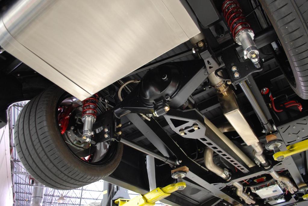
2 Speedtech s C10 shop truck was used to develop the C10 ExtReme chassis. This is a complete street cruiser with all the amenities, yet has won 1 st place in the truck class again and again, performing along side top level purpose built cars in autocross and road course races. 2 P a g e
3 Thank you for purchasing your new Speedtech ExtReme Chassis kit. Installing this product will require the removal of your old frame, engine and transmission from the car. Take all necessary precautions whenever jacking up your vehicle and use safe and sturdy jack stands to support the vehicle whenever it is off the ground. Be sure to take all other safety precautions required to do the job correctly. Read all instructions thoroughly before beginning any assembly. For the most part, initial assembly and set up of your new suspension can be done in a home garage with simple hand tools. Included in these tools should be a quality torque wrench, anti-seize lubricant, blue Loctite, and suspension grease. As your final step, go over each assembly step again to be sure all fasteners are correctly secured. Once assembled you will need a professional wheel alignment performed. Driving the vehicle without a proper alignment can be dangerous, towing is recommended. Info on setting toe close enough to drive onto a trailer is with our performance alignment instructions on page 31. After assembly you still have work to do. While Speedtech's ExtReme suspension systems work great as a direct bolt in replacement for your factory suspension, they are also designed to meet the needs of those intending to race their vehicles on a regular basis. Part of having this versatility includes some anticipated adjusting and tuning of the suspension to achieve maximum performance results for each individual driver, vehicle and type of racing. Some of this, such as tuning sway bars and shock settings, can be done track side through making adjustments and seeing/ feeling how the car reacts to these changes. We recommend a tire probe pyrometer and good quality air pressure gauge be in your track side tuning kit. Other adjustments, such as tuning bump steer and caster may require specialized equipment and professional help. Speedtech's technical department can share insight on making some of these adjustments, however we are somewhat limited to how much help we can offer over a phone call. If you require help with a more thorough chassis set up for a specific racing application we recommend a reputable professional coach such as Ron Sutton Race Technologies. These resources can be a great help in getting the most out of your particular car. Good luck and enjoy your build! 3 P a g e

4 Additional parts you will need: LS Oil Pan LS Engine Starter Motor LS Engine Adapter Plates Engine to frame Motor Mounts Headers Transmission mount Steering Shaft Kit Custom Brake Line Kit 12mm x 1.5 Lug Nuts LS Oil Pan- Factory LS oil pans will have clearance issues and will not work. Other aftermarket pans may work however we have not test fit any outside of our Speedtech fabricated pans. Speedtech offers two types of LSx oil pans for use with our sub frames. Pictured above is the ATS # LSx Road Race oil pan. It features internal baffling, trap doors and a windage tray. It also features bungs and fittings for remote oil filter mount, oil pressure and temp gauges, and turbo oil line. Also available from Speedtech is the ATS # LS7 and LS9 dry sump oil pans. These pans feature all internal and external passages for the use of a dry sump style oiling system. Please call us at for more details. 4 P a g e

5 Engine Starter- For the most amount of clearance we suggest using a GM starter for a Corvette, or equivalent Powermaster #9201. Speedtech does not carry these starters. Engine Mounts- When installing your engine you must use an LS motor mount adapter plate, we recommend the ATS # and our Speedtech custom machined polyurethane motor mounts # Transmission Mount- An Energy Suspension polyurethane transmission mount can be purchased from Speedtech, part # Headers- Our ExtReme subframes have very tight fitting frame rails for additional wide tire clearance and steering angle. If you have not already purchased headers, Speedtech has designed 1 7/8" long tube headers specifically for our ExtReme frames that fit Chevrolet LSx, engines. They are designed to optimize engine to frame clearance as well as ground clearance for lowered vehicles. Please call us at for specific part numbers for your application. Note: Because we have designed our own headers specifically for Speedtech ExtReme frames, we will not be testing any other brand of headers for fitment clearance. We do not know what other brands of headers, if any, might fit. 5 P a g e


6 Steering Shaft- You will need to order a steering shaft connection according to your specific vehicle and steering column type. Speedtech offers several different configurations that meet most needs. Call us at for specific part numbers. Note: It is imperative when setting up and installing the steering shaft that the shaft does not protrude beyond the end of the u-joint housing. Damage and binding will occur if this is not installed properly. The steering shaft is typically left long to allow for trimming. Mock up the shaft assembly in place and trim as needed to ensure that the correct length is achieved. When installing the shaft you will find one end is splined to allow the shaft to be rotated and phased to eliminate any binding. You may have to adjust the phasing slightly from this initial starting position to allow smooth operation and completely eliminate any binding. Brake Lines- Factory brake lines will not work with an ExtReme frame. Custom brake lines must be made up. Refer brake line construction only to those with professional level experience. 6 P a g e
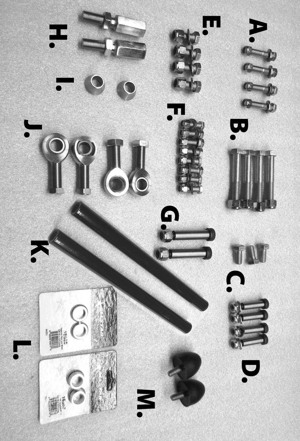
7 Front Suspension Hardware Kit Checklist A. 4- Upper control arm cross shaft bolts 7/16 x 2 ¼" 4- Upper control arm cross shaft nylock nuts 7/16" 4- Upper control arm washers 7/16" B. 4- Lower Control arm bolts 9/16 x 3 ½" 4- Lower Control arm nylock nuts 9/16" C. 3- Rack mount bolts ½ x 1" Course D. 4-1/2" Shock mount shoulder bolts, 3/8" course thread 4- Shock mount nylock nuts 3/8 Course 4- Shock mount washers 3/8. E. 4- Engine stand ½ x 1 ¼ 4- Engine stand nylock nuts 1/2" 4- Engine stand Washers 1/2" F. 8- Transmission crossmember bolts 3/8 x 1 1/4" 8- Transmission crossmember nylock nuts 3/8 16- Transmission mount flat washer 3/8" G. 2- Outer tie rod Shoulder bolt 5/8 x 2 ½" 2- Outer tie rod bolt nylock nuts ½" Course H. 2- Inner steering tube adjusters 2- Left hand jam nuts for adjuster I. 2- Stainless inner tie rod heim spacers.650 tall J. 4- Inner / Outer 5/8 tie rod heim Joints right hand 2- Jam nuts 5/8" Right hand for inner heim joint 2- Jam nuts 5/8" Right SMALL OUTSIDE DIAMETER for the Heim Joint at steering arm end K. 2- Tie rod tubes L. 1 PK outer tie rod heim joint spacers.500 tall 2 PK outer tie rod heim joint spacers.250 tall M. 2- Bump stops lower (tall cone shape) Sway bar mounting hardware is included with the sway bar and billet steering arm hardware is included with the steering arms. 7 P a g e
8 8 P a g e

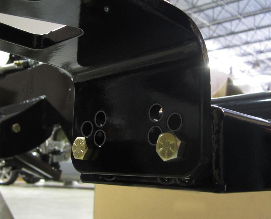
9 Assembly 1. Support your chassis with jack stands at each corner, be sure it is sturdy and level. For powder coated frames, use something non abrasive such as a shop rag between the stands and frame to protect the finish. 2. Install the supplied engine mount frame stands in the forward locations shown below. Do not fully tighten the bolts at this time to allow adjustment later when installing the engine. Note: If using a low mount A/C compressor or an external oil pump drive, the rear holes may be used for extra clearance on the passenger side. You may also use the rearward mounting holes on both sides if you are attempting engine set back. Other modifications may be required for engine set back such as increasing firewall to engine clearance. Note: LS Series motors use 2 different length frame stands, the Taller Stand must be installed on the Driver Side. This will move the motor over 1/2 to clear the oil pan rail. You must also us an LS motor mount adapter such as the ATS # P a g e

10 4. Install the lower control arms. Begin by sliding the frame end up into the frame pockets. The boxed portion of the arm will be towards the front. Note: For maximum performance Speedtech component tolerances are designed to be tight. Excessive thickness of paint or powder coating may require additional effort for installation of lower control arms. 10 P a g e

11 Apply anti-seize lubricant to the shank of the 9/16 x 3 1/2" bolts and install with 9/16" nylock nuts. Torque to 70 ft. lbs. 11 P a g e

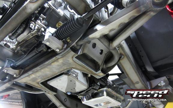
12 5. Using the three 1/2 x 1" bolts, secure the steering rack to the frame. Note the bolts will thread in from the underside. Use Blue Loctite and torque to 40 ft. lbs. 12 P a g e

13 13 P a g e
14 ExtReme Power Steering System Requirements The Sweet dual power steering rack is a very high quality part. Considering the way Speedtech has spec d its internals for maximum all round performance and through extensive testing and racing our Sweet equipped test cars we have come up with the following critical requirements to ensure proper function, reliability, and longevity of your power steering system. The use of a very high quality power steering pump is required We recommend either Jones Racing or Sweet Manufacturing. Both of these pumps are hand built and have extensive internal modifications to increase both performance and longevity over any other pump that we are aware of. Do not use a factory style or spec'ed steering pump. MAXIMIM RPM of the steering pump is 5200 RPM Please ensure your pullies are sized for this max speed accordingly with max engine RPM. Although individual needs may vary, we generally recommend: 5 crank Pulley 6.5 power steering pulley Required Power Steering Pump Specifications 3+ Gallons per minute 1300 psi We recommend a series 60 eccentric in the power steering pump. You MUST use a quality power steering cooler Minimum of at least 44 sq inches. You MUST use a high quality fluid, we recommend Jones full synthetic, or Sweet full synthetic 14 P a g e
15 6. Assemble the coilover shocks as shown below. Start by installing the large adjusting nuts threaded to the bottom of the shock. Install the adjusting thrust bearings and washers on top of the nuts prior to the spring. Install the spring and spring cap. The spring may need to be compressed in order to get the cap on correctly. 15 P a g e

16 7. Install the shock into the lower control arm and the upper shock mount. Install the socket head shoulder bolts and accompanying nylock nuts and tighten them to 20 ft/lbs. Note: For vehicles using our down tube chassis braces, install the upper shock mount bolt with the nut on the front side and the bolt head towards the firewall. This will enable shock removal without removing the chassis brace tube. 16 P a g e

17 8. Assemble a matching set of caster alignment slugs into the upper control arms. Note only one side of the control arm cross shaft is machined for the slugs. 17 P a g e

18 A. The front (A.) of the arm is where the slug pocket is closer to the control arm bushing, see below. B. There are three different caster slug settings in only two pairs of slugs. One pair has a centered bolt hole and is 8 degrees caster. The other pair has an offset bolt hole. With the hole towards the rear you will have 7 degrees of caster. With the hole to the front you will have 9 degrees of caster. Be sure all four slugs are offset in the same direction! *Refer to the alignment specs at the end of these instruction sheets for initial caster settings for different types of driving. 18 P a g e


19 Install arms with the cross shafts on the inside of the frame mounts using the 7/16 x 2 1/4" Bolts. Tighten as needed; the alignment shop will torque them to specs. Note brake line mount loop on frame below front control arm bushing. 19 P a g e

20 9. Install the spindles onto the control arms. Note the brake caliper mounts will be to the rear side of the spindle. Tighten the lower ball joint to 60 ft/lbs and install the cotter pin. Tighten the upper ball joint to 40 ft/lbs. and install the cotter pin. Install the billet steering arms with the tie rod end towards the front and curved outwards. With the nuts on the outside, torque the two steering arm to spindle socket head bolts and nylock nuts to 50 ft. lbs. 20 P a g e
 To be able to achieve a full range of toe adjustment, thread the adjuster into the sleeve about one turn. Then thread the heim joint into the adjuster the same amount, about one turn.")
21 10. Assemble the tie rod assemblies. Apply Anti-seize to female end threads on the sleeve and the adjuster. A.) Thread outer steering arm side almost all the way in and lock down with the lock nut. B.) To be able to achieve a full range of toe adjustment, thread the adjuster into the sleeve about one turn. Then thread the heim joint into the adjuster the same amount, about one turn. While holding the heim and sleeve steady, turn the adjuster to equally further engage the threads on both sides simultaneously. Initial toe set up is discussed at the end of the instructions near the alignment specs. Note: The SMALL OUTSIDE DIAMETER 5/8" lock down nuts should be used on the outer steering arm heim joint as seen below. DO NOT ignore this step! **Please read and closely follow assembly diagram on the next page. Photo below shows completed assembly. 21 P a g e
22 22 P a g e


23 Install the.650" bushing on the rack pin under the heim joint, See below. Install outer tie rod bushings as seen in the illustration below. This is an initial set up and can be tuned further with additional bushings not included in your kit. A bump steer gauge will be required to help you adjust it for specific needs. 23 P a g e
.")
24 11. We have found it easiest to assemble the sway bar one side at a time. Install one sway bar arm onto the center bar, (A.) then install one bushing onto the bar. Be sure to position the grease fitting where you will have easy access to it later. Note the arm curves outward. Assemble both sway bar end links so that they are 3 1/2" center to center, see (B.). Slide the assembled sway bar arm into the frame tube. Using the shaft as a guide, install the opposite side Delrin shaft bushing. Install one sway bar link onto the lower control arm and attach to the assembled sway bar arm (C.). Now install the second sway bar arm on the other side. Leave the second sway bar link off until you have the vehicle assembled and at ride height. At that point install the 2nd sway bar link. Note: For tuning purposes there are two positions for the sway bar link (C.). Using the forward hole increases spring rate, the rearward hole decreases spring rate. As you drive the car you may find you'd like to change the sway bar spring rate all together for different racing applications. This can easily be done by simply replacing the center sway bar shaft, you can reuse the sway bar arms and links included in this kit. 24 P a g e

25 12. Fully thread the bump stop up into the pre-tapped threads on the bottom side of frame. Bump stops should make contact near the rearward bar of the lower control arm at full compression. 25 P a g e


26 13. Install the transmission cross member. Offset top holes in center box are for LS applications. Small block and big block engines use top centered holes. Use remaining side holes as appropriate for your specific engine and transmission application. Do not fully tighten the bolts at this time to allow adjustment later when installing the engine and transmission. Note: the bolts for polyurethane transmission mounts are not included in the frame hardware kit. FRONT 26 P a g e

27 27 P a g e
28 Rear Suspension Hardware Kit Checklist TA = Torque Arm Panhard bar 2- Panhard Rod Ends with lock nuts 2- Panhard bar mount ½ x 2 ½ bolts, nuts and washers 2- rear axle bump stops 1- TA Front Pivot Bushing 1- TA Pivot pin 3/8 x ¾ Bolt, washer, and lock washer 2- TA Rear lower axle mount bushings 1-9/16 inner bore sleeve, 9/16 x 3 ¼ bolt and nut 2-9/16 washers 2-9/16x4 Front trailing arm mount bolts and nuts 2-9/16 Bolt sleeves 2- Billet spacers 2- ½ x3 ½ Rear trailing arm mount bolts, washers and nuts 2- ½ Bolt sleeves 2- Rear aluminum shock adapter 2-5/8 x 1 Adapter bolts ½ x 1 ¾ Upper shock mount shoulder bolt and nut /8x4 Lower shock mount shoulder bolt and nut /8x1 Extended shock mount bolts, washers and nuts Extended shock mount brackets 28 P a g e

29 29 P a g e

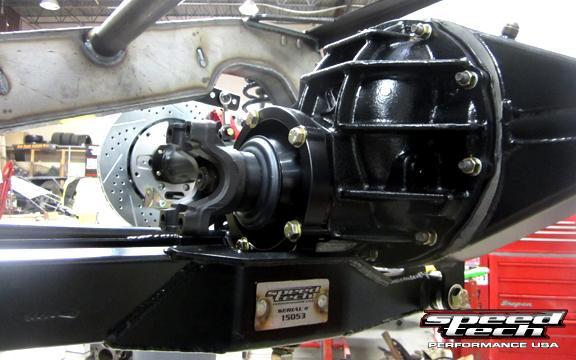
30 Rear Suspension Install 14. The billet pinion mount is a straight bolt-on over the existing pinion support. Remove the five original bolts, position the pinion mount, and reinstall using the new longer bolts supplied with the mount. Note: This bracket is designed to work with the original Ford pinion mount clocking position. Some aftermarket 9 centers have non- Ford clocking. Non-Ford pinion mount clocking WILL NOT WORK CORRECTLY. Please verify that your center is correct. If you are not sure, please contact your axle manufacturer before beginning the installation. 30 P a g e


31 15. Install the Torque Arm Delrin bushings. The front pin bushing is held in place using the 3/8 bolt and lock washer. Apply blue Loctite to the bolt threads. Assemble the rear bushings and 9/16 x 2 sleeve into the Torque Arm rear mount. 31 P a g e


32 16. Attach the torque arm to the axle housing. Loosely install both ½ x 2 bolts through the dog bone, torque arm and into the billet pinion mount. Attach rear housing mount with the 9/16x3 ¼ bolt and nylock nut. Raise the axle and Torque arm assembly up into position in the frame. Install the Torque Arm front pivot pin into the Torque Arm crossmember. 32 P a g e

33 17. Install the rear shock extension brackets to the axle trailing arm brackets with the 5/8x1 bolts and nylock nuts. Note there are two possible positions to adjust ride height. Torque to 50 lbs. Install billet shock adapters onto the extension brackets with the remaining 5/8x1 bolts, using the lower shock mount bolts to help align the billet adapters. Torque the 5/8 bolts to 50 lbs. Note that the adapters also allow 1½ of ride height adjustment depending on orientation. With the shock bolt on top ride height will be 1 ½ higher than with the shock bolt on the bottom. Axle brackets shown below are for visual purposes only, these brackets will come pre-welded to your axle housing. 33 P a g e

34 18. Install the rear shocks without the springs into the frame and attach to the rear axle. Do not completely tighten shock mounting bolts. 19. Apply blue Loctite to the threads on the short polyurethane bumpers and install into frame rails above axle tubes. 20. Trailing arms should be installed with the short end towards the front and grease zerk fittings pointing down. Install the rear trailing arm ends into the axle housing brackets using the ½ x 3 ½ bolts and nuts. Do not tighten completely. Install the front trailing arm ends with spacers using the 9/16 x3 ½ sleeves, bolts and nuts. Do not tighten completely. 21. Assemble the two tie rod ends into the panhard bar an equal amount of turns on each side. Install the assembly into the frame and axle housing mounts using the associated bolts. Do not tighten completely. 22. Optional rear sway bar can be installed at this time. Install bushings, bar and axle mount in the same manner as the front sway bar. Note the 3 possible positions. The sway bar spring rate will increase by using the axle mounts closer to the bar. 23. Using your jack raise the axle housing to your approximate ride height location. Your next step is to adjust the rear suspension, see page P a g e
 center the rear axle.")

35 Adjusting the Torque Arm System The panhard bar adjustment includes two threaded heim joints. Rotating the panhard bar will laterally (side to side) center the rear axle. This is best measured with a plumb bob hanging down from the outside of each frame rail. The vertical panhard bar height adjustments are for adjusting the roll center. For a base setting, it is recommended to set the bar parallel to the ground at ride height with all the finished weight in the car. 35 P a g e

36 Trailing arm length is adjustable and is pre set during manufacturing. Fine tuning the length to center the wheels in the wheel opening may be required. This is done by rotating the arms right to shorten and left to lengthen. See diagram below. Trailing arms should be set close to parallel to the ground at ride height and can be adjusted to any hole position in the rear axle bracket to increase or decrease anti squat. Lowering the rear of the arm increases anti squat, helping to increase traction. Installing them near parallel to the ground is the recommended base starting point. 36 P a g e
37 With all finished weight in the car adjust the pinion angle by shimming between the billet pinion mount and the torque arm. Be sure to check drive shaft clearance while doing this. Note: Pinion angle should be set to between 0-2 degrees from the crank shaft angle, not level to the ground. For example If you put a digital degree gauge or inclinometer on the face of the crank pulley and it reads 87 degrees then you should set the pinion at between degrees. 37 P a g e

38 For coil over adjustment, use the threaded nuts on the shock to fine tune the ride height. The shock should have approximately 2 of travel both in compression and extension. Once adjusted you should be able to see 2 of shock shaft when the car is at ride height to avoid bottoming out the shock. Ideally the adjusting nuts should be approximately at or slightly lower than the middle of the adjustment threads. If you have to adjust the spring nuts all the way up the shock body to raise the vehicle to the desired height then the springs are too soft for the weight of your car. For shock dampening adjustment, depending on the shocks you ordered, there are different amounts of adjustment. On all shocks, turning the adjustment knob counter clockwise will generally soften the ride and clockwise will stiffen the ride. On a single adjustable shock the adjustment affects both the compression (bump) and extension (rebound). Follow the coil over manufacturer s recommendation on any adjustments Feel free to contact us with any specific tuning questions. 38 P a g e
39 FINAL PREP BEFORE DRIVING Be sure that all measurements are correct, and re check that all components have proper clearance throughout your suspension s travel range. Install chassis into the vehicle. Torque all body mount bolts to 140 ft/lbs. Tighten all loose suspension bolts and recheck all bolts to ensure they are all tight. It is recommended you fill all grease fittings at this time, we suggest using Permatex Ultra Slick Synthetic Grease, but any high quality chassis grease will do. For your Sweet power rack and pinion we recommend using Sweet or Jones brand full synthetic power steering fluid for best performance and to avoid overheating standard type fluids during performance driving situations. DIFFERENTIAL CARE, BREAK-IN, and WARRANTY INFORMATION OIL REQUIREMENTS For Tru Trac and Wavetrack posi units, use a quality petroleum/mineral based oil. We do not recommend synthetic oil. Friction additive/modifier is not required. Do not use any RedLine, Shockproof, Royal Purple or similar gear oils. Specifically any standard 75W 90 or 140 will work just fine. OIL LEVEL Many differentials are easy to fill with gear oil. However, the 9 Ford design can be difficult to fill completely. The location of the fill plug on the 9 Ford can cause oil to run back out before it is completely full. Most 9 housings hold at least 2 1/2 3 quarts of oil and sometimes as much as 5 quarts. It is important to take your time and be sure that the oil has settled into all the crevices and recheck the oil level to be certain that it is completely full before driving the vehicle. BREAK IN ANY OVERLOADING OR OVERHEATING WILL CAUSE THE GEAR OIL TO BREAK DOWN AND THE RING & PINION WILL FAIL. All new gear sets require a break-in period to prevent damage from overheating. After driving the first 15 to 20 miles, it is best to stop and let the differential cool before proceeding. Dutchman s warranty requires at least 500 miles before towing. DMI also requires towing for very short distances (less than 15 miles) and letting the differential cool before continuing during the first 45 towing miles. This may seem unnecessary, but it is very easy to damage the differential by loading it before the gear set is completely broken in. DMI recommends changing the oil after the first 500 miles. This will remove any metal particles or phosphorus coating that has come from the new gear set. The greatest damage results when a new ring & pinion has been run for several miles during the first 500 miles and the oil is very hot. Any heavy use or overloading at this time will cause irreparable damage to the gear set that can be determined by inspection and will not be warranted by DMI. 39 P a g e
40 CLUTCH TYPE POSITRACTIONS Positraction chatter is normal for limited slip and clutch type positraction differentials. Both rear tires must measure the same circumference in order for the differential to function properly without premature wear. Limited slip additive or friction modifier for limited slip differentials must be used with the oil to reduce positraction chatter in the event that the oil is changed. LOCKERS Mechanical Locking differentials will bang and clunk during normal operation. Both rear tires must measure the same circumference in order for a locking differential to function properly. GEAR NOISE Richmond Gear and other aftermarket (non OEM) gears are designed primarily for strength and may be noisy. This noise is especially inherent in vans and quiet passenger cars. SIGNS OF LUBRICATION FAILURE When a gear runs low on oil, damage is sure to result. The cause of damage is not always obvious. When a differential runs low on oil, the oil volume may not be sufficient to keep the gear cool. Once the oil breaks down from contact with the hot gear, wear occurs very rapidly. Material will wear off the drive side of both the ring & pinion teeth and leave a feather like pattern on both surfaces. A gear that wears from friction due to lack of lubrication and excessive heat seldom experiences a color change from heat because any discoloration is worn off the teeth during each contact. Ring & Pinion gears are heat treated separately so that the pinion, whose teeth make contact more often than the ring gear, is designed to be harder. To accomplish this, the two gears are heat treated separately and a soft gear will not cause both the ring & pinion to wear. DUTCHMAN AXLE WARRANTY EXCLUSIONS 1. Any damage due to abuse, overloading, or lubrication failure (e.g. oil deterioration, water contamination, low oil level). 2. Any vehicles used off road or for competition. 3. Mini and mid-sized vehicles with tires over 31 tall will not be warranted due to the overloading caused by tall tires. 40 P a g e

41 Most items are not warranted against abuse, overloading, or improper lubrication. All rear axle parts must be returned to DUTCHMAN'S shop freight prepaid for inspection and determination. We do not authorize and will not pay for outside repairs. ANY UNAUTHORIZED OUTSIDE REPAIRS OR MODIFICATIONS VOID THIS WARRANTY. We will not pay for labor, inconvenience, loss of time or revenue, telephone calls, commercial losses, or loss of perishable goods. This is our only warranty expressed or implied. All returned goods must be accompanied by copy of purchase invoice within 30 days and will be charged a 20% service charge for handling. Reference photos 41 P a g e

42 42 P a g e

43 43 P a g e

44 44 P a g e

45 Do not drive the vehicle until it has had a proper suspension alignment. Once you have completed the chassis install, we recommend you have the vehicle towed to a competent professional alignment shop to have the alignment performed. Measuring the front tires, center to center on both the front and the back side. With the car at ride height and the steering wheel straight, adjust accordingly to get the front of the tire and the rear of the tire measurement as close as possible to each other. This should be good enough to safely drive up onto a trailer or tow vehicle. Note: Use our suggested alignment specifications, DO NOT allow the alignment shop to use pre-programmed factory alignment specs! If your chosen alignment shop cannot match our suggestions, find a different shop familiar with performance alignment set-up. Alignment Specifications Extreme Chassis Systems Note: These are only suggestions and may need additional changes to achieve the optimum settings for your driving style or situation. If you are unsure which set-up to use, please call our technical department for help at P a g e
46 Daily Driving, Street Performance Specifications Driver Side Passenger Side 7 Deg. positive Caster 7 1/4 (7.25) Deg. positive Caster 1/2 (.5) Deg. negative Camber 1/2 (.5) Deg. negative Camber 3/32 Total Toe-in Stiff Front Spring Rate/Low Travel Set Up (550# & Higher front springs) Driver Side Passenger Side 9 Deg. positive Caster 9 1/4 (9.25) Deg. positive Caster 1 3/4 (1.75) Deg. negative Camber 1 3/4 (1.75) Deg. negative Camber 1/8 Total Toe-OUT Moderate Front Spring Rate/Mid Travel Set-up ( # front springs) Driver Side Passenger Side 9 Deg. positive Caster 9 1/4 (9.25) Deg. positive Caster 1 1/4 (1.25) Deg. negative Camber 1 1/4 (1.25) Deg. negative Camber 1/8 Total Toe-OUT Soft Front Spring Rate/High Travel Set-Up ( # front springs) Driver Side Passenger Side 9 Deg. positive Caster 9 1/4 (9.25) Deg. positive Caster 3/4 (.75) Deg. negative Camber 3/4 (.75) Deg. negative Camber 46 P a g e 1/8 Total Toe-OUT
47 1. Terms and Conditions of Sale 1. Effective January, 2008, supersedes all previous policy statements. Policies are subject to change without notice. Speed tech performance Ltd. is not responsible for printing errors. 2. Speedtech Performance USA LLC. does not endorse, nor recommend modification of vehicles for use on public highways, since warranty or government regulations may be violated. As an express condition of sale of any performance part, the buyer acknowledges and agrees to use the performance parts for the modification of vehicles in sanctioned OFF-ROAD competitive events and show purposes only. Customers should exercise their discretion on matters with regards to the purchase and installation of these products. 3. Speedtech Performance USA LLC. does not ensure the legal use of these products. We do not guarantee the fitment of these products for anything other than there intended application nor do we assume any responsibilities what so ever for the misuse or losses incurred by the use of any of these components. While every effort is made to provide technical information and assistance, we have no control over owner installation, modification, and unusual stress that performance parts are subject to. 4. The customer acknowledges that Speedtech Performance USA LLC. and its employees are not responsible for any mechanical failures due to the use of parts sold, supplied or installed not for their intended application. Speedtech Performance USA LLC will not be held liable for any damages which are incurred directly or indirectly on the vehicles or operators or passengers of the vehicle. 5. Please consult your sales agent and/or technician prior to purchase of any of Speedtech Performance USA LLC products to ensure proper fit. The buyer assumes all responsibilities for determining the suitability of the product. All aftermarket products should always be installed by professionals only. 2. How to File a Warranty Claim: 1. Speed tech Performance Ltd. Warrants its products against materials and workmanship failure for the term of 12 months (1 year) from the date of purchase and only up to the amount paid with proof of purchase. 2. Seller s liability shall be limited to repairing or replacing, at its option, any defective product which is returned, freight prepaid to Seller, according to the Merchandise Return Procedure set forth in Section 3-B below. Buyer shall bear all responsibility for shipping charges and risk of loss or damage during transit to Seller. Products which have been subjected to abuse, misuse, alteration, neglect or unauthorized repair or installation, as determined solely by Seller, are not covered by this warranty. Any alterations, addition, improvements or attachments to the product(s) not authorized in writing by the Seller shall be deemed to be a waiver of this warranty by Buyer and shall render this warranty null and void. Seller shall return repaired or replaced product(s) to Buyer, at its expense via regular ground service in the U.S. Shipping charges by all other methods and to all other destinations shall be borne by Buyer. 3. As per section 3-B below, all shipments MUST be prepaid, include the original invoice and show the RGA on the outside of the package, otherwise it will be refused. Please include a brief explanation letter in order to expedite the warranty analysis process. This Warranty DOES NOT Cover- Removal, installation, shipment and insurance costs Improper installation or maintenance Alterations on the original design or unauthorized repairs. Normal wear and tear Misuse or abuse, negligence Damage to related components Costs incurred due to down time of vehicle 3. Merchandise General Return Procedure: A. If you purchased your Speedtech Performance USA LLC product from us or from an authorized dealer, you are covered by the terms of our general product return policy. All claims however, must be submitted directly to Speedtech Performance USA LLC. The answer to ALL of the following questions should be YES before contacting our Customer Service Department. 1. Is the part appropriate to your application? 2. Did you carefully and thoroughly read the instructions provided along with the part? 3. Do you have the proof of purchase? 4. Are you the original purchaser? 5. Is the part unmodified and clean? 6. Is the return date within 3 months from the purchase date? 7. Is the reason for return a legitimate product defect? If all answers are yes, please do the following: B. Call our customer service representatives at Provide the invoice number, date of purchase and reason for return You will be assigned a Returned Goods Authorization Number (RGA) valid for 30 days. The package you return must show the RGA on the outside of the package, include a copy of the original invoice and be shipped prepaid to our facility. The part has to be in its original packaging materials and be in a resellable condition. For parts presenting signs of installation and/ or use, only warranty claims will be accepted. Ship to seller, freight pre-paid and insured for replacement cost in original packaging. Replacement or repair decision will be made when merchandise is received by seller. No advance replacement is available. A Restocking fee may be applied. All warranties implied by law are limited in duration of this warranty. You have specific rights that may vary from state to state or Province to Province. By purchasing any of the products that are manufactured by speed tech performance you agree to any and all of the above terms and conditions. Copyright Speedtech Performance USA LLC 47 P a g e
48 Speedtech Performance USA LLC 3884 S. River Rd. Bldg A St. George, UT (435) Notes 48 P a g e
Installation Instructions
 Oct 3, 2017 1967-1969 Camaro and 1968-74 Nova Complete Sub Frame Installation Instructions The following instructions are intended for professional installers and are guidelines only. Speedtech Performance
Feb 22, 2018 '67-69 Camaro & '68-74 Nova Bumpsteer Adjustment Kit
 Feb 22, 2018 '67-69 Camaro & '68-74 Nova Bumpsteer Adjustment Kit 10552 The following instructions are intended for professional installers. Speedtech Performance assumes NO responsibility for the installation
'64-72 Chevelle/ A Body Rear Coilover Conversion Kit
 Nov 3, 2017 '64-72 Chevelle/ A Body Rear Coilover Conversion Kit Includes instructions for Currie Brand Axles The following instructions are intended for professional installers and are guidelines only.
Installation Instructions
 Nov 3, 2017 G-Body Rear Coilover Conversion Kit 1 P a g e Installation Instructions The following instructions are intended for professional installers and are guidelines only. Speedtech Performance assumes
'64-72 Chevelle/ A Body Rear Coilover Conversion Kit
 February 3, 2014 '64-72 Chevelle/ A Body Rear Coilover Conversion Kit Includes instructions for Currie Brand Axles The following instructions are intended for professional installers and are guidelines
Dec 1, 2017 ATS AFX Spindle Installation Instructions
 Dec 1, 2017 ATS AFX Spindle Installation Instructions 1 P a g e The following instructions are intended for professional installers and are guidelines only. Speedtech Performance assumes NO responsibility
94-96 Impala SS/ B-Body Rear Coilover Conversion Kit
 January 29, 2014 94-96 Impala SS/ B-Body Rear Coilover Conversion Kit The following instructions are intended for professional installers and are guidelines only. Speedtech Performance assumes NO responsibility
Aug 24, 2017 ATS AFX Spindle Installation Instructions
 Aug 24, 2017 ATS AFX Spindle Installation Instructions 1 P a g e The following instructions are intended for professional installers and are guidelines only. Speedtech Performance assumes NO responsibility
78-88 G Body Rear Trailing Arm Kit
 May 14, 2014 78-88 G Body Rear Trailing Arm Kit Parts in this kit may vary slightly from photo. The following instructions are intended for professional installers and are guidelines only. Speedtech Performance
Chicane Coilover Kit For '64 to '72 Chevelle/ A Body. Installation Instructions
 Nov 3, 2017 Chicane Coilover Kit For '64 to '72 Chevelle/ A Body Installation Instructions Actual parts may vary from photo depending on application. 1 P a g e The following instructions are intended for
Chicane Coilover Kit For '70 to '81 Camaro/Firebird
 Nov 25, 2013 Chicane Coilover Kit For '70 to '81 Camaro/Firebird 1 P a g e Installation Instructions The following instructions are intended for professional installers and are guidelines only. Speedtech
Installation Instructions
 Nov 25, 2013 Upper Control Arms Installation Instructions The following instructions are intended for professional installers and are guidelines only. Speedtech Performance assumes NO responsibility for
Installation Instructions
 Mar 13, 2018 1955-1957 Chevy Smooth Firewall Part number 81511 Installation Instructions The following instructions are intended for professional installers and are guidelines only. Speedtech Performance
Installation Instructions
 May 8, 2018 Torque Arm Rear Suspension For 70-81 Camaro/Firebird Parts may vary from photo depending on year of vehicle. Installation Instructions The following instructions are intended for professional
June 22, ExtReme Chassis Chevelle
 June 22, 2018 ExtReme Chassis 1964-72 Chevelle Photo above shows optional stainless fuel tank and supercharged LS drive train. Call us for more details on those parts! The following instructions are intended
June 22, ExtReme Chassis Chevelle
 June 22, 2018 ExtReme Chassis 1964-72 Chevelle Photo above shows optional stainless fuel tank and supercharged LS drive train. Call us for more details on those parts! The following instructions are intended
Installation Instructions
 Nov 25, 2013 Custom Bent Brake Line Kit '67-'69 Camaro and '68-'74 Nova Installation Instructions The following instructions are intended for professional installers and are guidelines only. Speedtech
Toll Free C5 & C4 Brake Bracket Installation Instructions
 Toll Free -888-467-65 www.speedtech-performance.com C5 & C4 Brake Bracket Installation Instructions Installation Instructions: Disclaimer All parts should be installed by a certified mechanic if you choose
1401 / 1402 / 1403 ADJUSTABLE TRAILING ARM MOUNT BRACES INSTALLATION OF HOTCHKIS PERFORMANCE ADJUSTABLE TRAILING ARM MOUNT BRACES
 1401 / 1402 / 1403 ADJUSTABLE TRAILING ARM MOUNT BRACES 1401 78-88 GM A/G-BODY / 1402 68-72 GM A-BODY / 1403 64-67 GM A-BODY Thank you for your purchase. Please call us at (562) 907-7757 if you have any
UPPER TRAILING ARM REMOVAL
 #1204 MUSTANG UPPER TRAILING ARMS Thank you for your purchase. Please call us at (562) 907-7757 if you have any questions regarding your Hotchkis Performance products. Visit us online @ www.hotchkis.net
Rear Upper Camber Link (12425) Scion tc
 Scion tc") Rear Upper Camber Link (12425) Scion tc Thank you for your purchase from our new line of Scion tc parts. Please call us at (877) 4NO-ROLL if you have any questions regarding the service or installation
Rear Upper Camber Link (12425) Scion tc Thank you for your purchase from our new line of Scion tc parts. Please call us at (877) 4NO-ROLL if you have any questions regarding the service or installation
1401 / 1402 / 1403 ADJUSTABLE TRAILING ARM MOUNT BRACES INSTALLATION OF HOTCHKIS PERFORMANCE ADJUSTABLE TRAILING ARM MOUNT BRACES
 1401 / 1402 / 1403 ADJUSTABLE TRAILING ARM MOUNT BRACES 1401 78-88 GM A/G-BODY / 1402 68-72 GM A-BODY / 1403 64-67 GM A-BODY Thank you for your purchase. Please call us at (562) 907-7757 if you have any
1107 Tubular Upper A-Arms Camaro/Firebird
 1107 Tubular Upper A-Arms 67-69 Camaro/Firebird Thank you for your purchase from our new line of F-Body parts. Please call us at (877) 4NO - ROLL if you have any questions regarding the service or installation
Tubular Lower A-Arms GM A-Body Tubular Lower A-Arms GM F-Body
 1104 - Tubular Lower A-Arms 64-72 GM A-Body 1108 - Tubular Lower A-Arms 70-81 GM F-Body Tubular Lower A-Arms: Thank you for your purchase from our new line of A-Body parts. Please call us at (877) 4NO
1109 Tubular Lower A-Arms Camaro/Firebird
 1109 Tubular Lower A-Arms 67-69 Camaro/Firebird Tubular Lower A-Arms: Thank you for your purchase from our new line of F-Body parts. Please call us at (877) 4NO - ROLL if you have any questions regarding
2253 FRONT AND REAR SPORT SWAY BAR SET CHEVROLET B-BODY
 2253 FRONT AND REAR SPORT SWAY BAR SET 65-66 CHEVROLET B-BODY Thank you for your purchase from our line of classic Chevrolet B-body suspension parts. Please call us at (877) 4NO-ROLL if you have any questions
Rear Upper Camber Link (12425) Scion tc
 Scion tc") Rear Upper Camber Link (12425) Scion tc Thank you for your purchase from our new line of Scion tc parts. Please call us at (877) 4NO-ROLL if you have any questions regarding the service or installation
Rear Upper Camber Link (12425) Scion tc Thank you for your purchase from our new line of Scion tc parts. Please call us at (877) 4NO-ROLL if you have any questions regarding the service or installation
5) The trailing arm should then pivot smoothly on the chassis. 6) Install the rear bolt. 7) Place one drop of blue Loctite
 The trailing arm should then pivot smoothly on the chassis. 6) Install the rear bolt. 7) Place one drop of blue Loctite") INSTALLATION INSTRUCTIONS 1301 / 1302 / 1305 / 1306 THANK YOU FOR CHOOSING HOTCHKIS PERFORMANCE PRODUCTS Removal of Stock Lower Trailing Arms 1) Place car on level surface. 2) Support rear of the car on
INSTALLATION INSTRUCTIONS 1301 / 1302 / 1305 / 1306 THANK YOU FOR CHOOSING HOTCHKIS PERFORMANCE PRODUCTS Removal of Stock Lower Trailing Arms 1) Place car on level surface. 2) Support rear of the car on
Sport Sway Bar Kit VW Golf (GTI ), Jetta
, Jetta") Sport Sway Bar Kit 22813 VW Golf (GTI ), Jetta Thank you for your purchase from our new line of VW parts. Please call us at (877) 4NO - ROLL if you have any questions regarding the service or installation
Sport Sway Bar Kit 22813 VW Golf (GTI ), Jetta Thank you for your purchase from our new line of VW parts. Please call us at (877) 4NO - ROLL if you have any questions regarding the service or installation
IMPORTANT NOTICE Stock Height OEM Spindle
 IMPORTANT NOTICE Ball Joint Info: Before you install this product, please verify which front spindles you have. We have designed the upper a arms to utilize the 73 87 style spindles. This type of spindle
MOVE ON TO THE REAR BAR INSTALLATION
 22410 STREET SWAY BAR SET 2001-UP LEXUS IS300 Thank you for your purchase from our line of Lexus parts. Please call us at (877) 4NO-ROLL if you have any questions regarding the service or installation
BMW E46 M3 SPORT SWAY BAR SET # 22826
 BMW E46 M3 SPORT SWAY BAR SET # 22826 Thank you for your purchase from our new line of BMW E46 parts. Please call us at (877) 4NO - ROLL if you have any questions regarding the service or installation
1313 LOWER TRAILING ARMS CHEVROLET B-BODY
 1313 LOWER TRAILING ARMS 59-64 CHEVROLET B-BODY Thank you for your purchase from our line of classic Chevrolet B-body suspension parts.. Please call us at (877) 4NO-ROLL if you have any questions regarding
INSTALLATION INSTRUCTIONS QA1 P/N x400, x500, x600, x400, x500, x F100 Front Coil-over Suspension System
 INSTALLATION INSTRUCTIONS QA1 P/N 52620-x400, 52620-x500, 52620-x600, 52621-x400, 52621-x500, 52621-x600 65-72 F100 Front Coil-over Suspension System TOOLS AND SUPPLIES REQUIRED Floor Jack Two (2) Jack
INSTALLATION INSTRUCTIONS
 INSTALLATION INSTRUCTIONS SWAY BAR KITS # 2205 & 2206 Thank you for your purchase. Please call us at (562) 907-7757 if you have any questions about your Hotchkis Performance product. HOTCHKIS PERFORMANCE
Rear Suspension System C-10 Pickup Truck
 Rear Suspension System 18390 67-72 C-10 Pickup Truck Thank you for your purchase from our new line of Chevy parts. Please call us at 877-4NO - ROLL if you have any questions regarding the service or installation
Anti-Roll Bar Set # 2279, Cadillac CTS V6 & CTS-V
 Anti-Roll Bar Set # 2279, 2280 2003+ Cadillac CTS V6 & CTS-V Thank you for your purchase from our new line of CTS parts. Please call us at (877) 4NO-ROLL if you have any questions regarding the service
Sport Sway Bar Kit C-10 Truck
 Sport Sway Bar Kit 22390 67-72 C-10 Truck Thank you for your purchase from our new line of Chevy parts. Please call us at 877-4NO - ROLL if you have any questions regarding the service or installation
1204AA Ford Mustang Double Adjustable Trailing Arms
 1204AA 79-04 Ford Mustang Double Adjustable Trailing Arms Thank you for your purchase from our new line of Ford parts. Please call us at (877) 4NO-ROLL if you have any questions regarding the service or
2236 Sway Bar Installation Instructions
 2236 Sway Bar Installation Instructions Thank you for your purchase of this Hotchkis Performance product. Your stabilizer bar set was designed with the performance and durability you ve come to expect
INSTALLATION INSTRUCTIONS
 INSTALLATION INSTRUCTIONS 1301 / 1302 / 1305 / 1306 THANK YOU FOR CHOOSING HOTCHKIS PERFORMANCE PRODUCTS Removal of Stock Lower Trailing Arms 1) Place car on level surface. 2) Support rear of the car on
Sport Coil Springs set # Cadillac CTS
 Sport Coil Springs set # 1979 2003+ Cadillac CTS Thank you for your purchase from our new line of CTS parts. Please call us at (877) 4NO-ROLL if you have any questions regarding the service or installation
Sport Sway Bar Kit Chrylser E-Body Cuda, Challenger
 Sport Sway Bar Kit 2254 70-74 Chrylser E-Body Cuda, Challenger Thank you for your purchase from our new line of Mopar parts. Please call us at 877-4NO - ROLL if you have any questions regarding the service
2. Remove front wheels.
 1 PARTS DIAGRAM 2 Installation Instructions: (PASSENGER SIDE) 1. Place jack under center of RUV front end and lift until front wheels clear the ground. Be careful to support the RUV properly so that it
Sport Sway Bar Kit (22425) Scion tc
 Scion tc") Sport Sway Bar Kit (22425) Scion tc Thank you for your purchase from our new line of Scion tc parts. Please call us at (877) 4NO - ROLL if you have any questions regarding the service or installation of
Sport Sway Bar Kit (22425) Scion tc Thank you for your purchase from our new line of Scion tc parts. Please call us at (877) 4NO - ROLL if you have any questions regarding the service or installation of
2406 SPORT LEAF SPRINGS 2WD EXT/QUAD CAB 97-UP DODGE DAKOTA
 2406 SPORT LEAF SPRINGS 2WD EXT/QUAD CAB 97-UP DODGE DAKOTA Thank you for your purchase from our line of Dodge Dakota & Durango suspension parts. Please call us at (877) 4NO-ROLL if you have any questions
REAR SWAY BAR 2207R GM CAMARO/FIREBIRD
 REAR SWAY BAR 2207R 67-69 GM CAMARO/FIREBIRD Thank you for your purchase of this Hotchkis Performance product. Your stabilizer bar set was designed with the performance and durability you ve come to expect
1912F/ 1913F FRONT COIL SPRINGS 97-UP DODGE DAKOTA / DURANGO
 1912F/ 1913F FRONT COIL SPRINGS 97-UP DODGE DAKOTA / DURANGO Thank you for purchasing from our fine line of Dodge Dakota/Durango suspension parts. If you have any questions regarding the service and installation
4007 (Coupe) / 4008 (Convertible) Subframe Connectors Camaro/Firebird
 / 4008 (Convertible) Subframe Connectors Camaro/Firebird") 4007 (Coupe) / 4008 (Convertible) Subframe Connectors 67-69 Camaro/Firebird Thank you for your purchase from our new line of F-Body parts. Please call us at (877) 4NO - ROLL if you have any questions regarding
4007 (Coupe) / 4008 (Convertible) Subframe Connectors 67-69 Camaro/Firebird Thank you for your purchase from our new line of F-Body parts. Please call us at (877) 4NO - ROLL if you have any questions regarding
22421 SPORT SWAY BAR SET TOYOTA COROLLA
 22421 SPORT SWAY BAR SET 98-01 TOYOTA COROLLA Thank you for your purchase from our line of Corolla parts. Please call us at (877) 4NO-ROLL if you have any questions regarding the service or installation
WARNING!!! READ AND UNDERSTAND ALL INSTRUCTIONS BEFORE PROCEEDING. MAKE SURE THAT YOU HAVE ALL TOOLS AND PARTS BEFORE BEGINNING THE INSTALLATION.
 INSTALLATION INSTRUCTIONS FOR 2005-2015 TOYOTA TACOMA 4 X 4 AND PRERUNNER, 2003-2015 4RUNNER, 2007-2014 FJ CRUISER 1.5" FRONT LEVELING KIT PART NUMBER 415 WARNING!!! READ AND UNDERSTAND ALL INSTRUCTIONS
16366 Steering Tie Rods Chrysler B-Body, Charger, Super Bee, Road Runner, GTX Chrysler E-Body, Cuda, Challenger
 P 16366 66-70 B-Body, 70-74 E-Body 16366 Steering Tie Rods 1966-1970 Chrysler B-Body, Charger, Super Bee, Road Runner, GTX 1970-1974 Chrysler E-Body, Cuda, Challenger Thank you for your purchase from our
Rear Sway Bar Kit 22390R C-10 Truck
 Rear Sway Bar Kit 22390R 67-72 C-10 Truck Thank you for your purchase from our new line of Chevy parts. Please call us at 877-4NO - ROLL if you have any questions regarding the service or installation
PIVOT BUSHING KIT GM F-BODY
 PIVOT BUSHING KIT 21016 67-69 GM F-BODY 67-69 GM F-Body Pivot Bushing Kit Thank you for your purchase. Please call us at 877-4NO - ROLL if you have any questions regarding the service or installation of
2282R GM A Body Extreme Rear Sway Bar
 2282R 1964-1972 GM A Body Extreme Rear Sway Bar Thank you for your purchase from our new line of GM parts. Please call us at (877) 4NO - ROLL if you have any questions regarding the service or installation
WARNING!!! READ AND UNDERSTAND ALL INSTRUCTIONS BEFORE PROCEEDING. MAKE SURE THAT YOU HAVE ALL TOOLS AND PARTS BEFORE BEGINNING THE INSTALLATION.
 INSTALLATION INSTRUCTIONS FOR 2007-2015 JEEP JK 3 SUSPENSION LIFT SYSTEM PART NUMBER 587 WARNING!!! READ AND UNDERSTAND ALL INSTRUCTIONS BEFORE PROCEEDING. MAKE SURE THAT YOU HAVE ALL TOOLS AND PARTS BEFORE
Sport Sway Bar Kit (22431 ) Subaru Forester INSTALLATION OF HOTCHKIS FRONT SWAY BAR
 Subaru Forester INSTALLATION OF HOTCHKIS FRONT SWAY BAR") Sport Sway Bar Kit (22431 ) Subaru Forester Thank you for your purchase from our new line of Forester parts. Please call us at (877) 4NO - ROLL if you have any questions regarding the service or installation
Sport Sway Bar Kit (22431 ) Subaru Forester Thank you for your purchase from our new line of Forester parts. Please call us at (877) 4NO - ROLL if you have any questions regarding the service or installation
CHEVY / GMC 1500HD / 2500HD 2WD 8 LUG 7 BASIC KIT
 85101 2000-2010 CHEVY / GMC 1500HD / 2500HD 2WD 8 LUG 7 BASIC KIT C8510-4 MAIN BOX KIT W/ HARDWARE 1) FRONT X MEMBER 1) REAR X MEMBER 2) TORSION BAR DROPS 1) LEFT BUMP STOP 1) RIGHT BUMP STOP 2) SWAY BAR
2000+ Silverado x4 P/N 2230
 2000+ Silverado 1500 4x4 P/N 2230 Thank you for your purchase of this Hotchkis product. Your Hotchkis Sway Bars were designed with the performance and durability you ve come to expect from Hotchkis Performance.
Sport Coil Springs (19425) Scion tc
 Scion tc") Sport Coil Springs (19425) Scion tc Thank you for your purchase from our new line of Scion tc parts. Please call us at (877) 4NO-ROLL if you have any questions regarding the service or installation of
Sport Coil Springs (19425) Scion tc Thank you for your purchase from our new line of Scion tc parts. Please call us at (877) 4NO-ROLL if you have any questions regarding the service or installation of
(WILL NOT FIT VEHICLES WITH X-REAS SUSPENSION)
") 2003-2016 TOYOTA 4RUNNER/2007-2014 FJ CRUISER 4WD INSTRUCTIONS 3 SUSPENSION LIFT KIT P/N 40021 (WILL NOT FIT VEHICLES WITH X-REAS SUSPENSION) WARNING!!!! PRODUCT SAFETY LABEL MUST BE INSTALLED INSIDE THE
2003-2016 TOYOTA 4RUNNER/2007-2014 FJ CRUISER 4WD INSTRUCTIONS 3 SUSPENSION LIFT KIT P/N 40021 (WILL NOT FIT VEHICLES WITH X-REAS SUSPENSION) WARNING!!!! PRODUCT SAFETY LABEL MUST BE INSTALLED INSIDE THE
INSTALLATION OF HOTCHKIS FRONT STABILIZER BAR
 22441 FRONT AND REAR SPORT SWAY BAR SET Infiniti G37/S Coupe & G35/S Sedan Thank you for your purchase from our Hotchkis line of suspension parts. Please call us at (877) 4NO-ROLL if you have any questions
22427 SWAY BAR SET 2002-UP SUBARU WRX WAGON
 22427 SWAY BAR SET 2002-UP SUBARU WRX WAGON Thank you for your purchase from our line of Subaru WRX parts. Please call us at (877) 4NO-ROLL if you have any questions regarding the service or installation
Index. Page Number Section
 S H O C K S Index Page Number Section 1-4 GM Front Coil Over Installation 5-7 Front Smooth Body Shock Installation 7-8 Rear Smooth Body Shock Installation 8-11 Custom Coil Over Installation 12 Tuning and
SPECIAL TOOLS REQUIRED:
 INSTALLATION INSTRUCTIONS FOR 2010-15 TOYOTA 4RUNNER WITH XREAS SUSPENSION 3 SUSPENSION LIFT KIT PART NUMBER 432X WARNING!!! READ AND UNDERSTAND ALL INSTRUCTIONS BEFORE PROCEEDING. MAKE SURE THAT YOU HAVE
Chrysler A-Body Tubular A-Arms Installation Instructions A-ARM INSTALLATION
 1967-1976 Dodge Demon 1112 67-72 Chrysler A-Body Tubular A-Arms Installation Instructions Thank you for your purchase of this Hotchkis Performance product. Your A-Arm set was designed with the performance
FRONT BAR INSTRUCTIONS
 2228, 2229, 2230, 2231 & 2232 Sway Bar Installation Instructions. 99+ Chevrolet Silverado/GMC Seirra Pickups FRONT BAR INSTRUCTIONS *NOTICE HOW THE STOCK SWAY BAR LOOKS i.e. BRACKET PLACEMENT, BENDS, etc.
INSTALLATION INSTRUCTIONS FOR 2016 TOYOTA TACOMA 4 X 4 AND PRE RUNNER 3 SUSPENSION LIFT KIT PART NUMBER
 INSTALLATION INSTRUCTIONS FOR 2016 TOYOTA TACOMA 4 X 4 AND PRE RUNNER 3 SUSPENSION LIFT KIT PART NUMBER 427 WARNING!!! READ AND UNDERSTAND ALL INSTRUCTIONS BEFORE PROCEEDING. MAKE SURE THAT YOU HAVE ALL
PARTS LIST INCLUDED IN KIT TORQUE SPECIFICATIONS PRODUCT SAFETY LABEL MUST BE INSTALLED INSIDE CAB IN PLAIN VIEW OF ALL OCCUPANTS.
 INSTALLATION INSTRUCTIONS FOR 2010-15 TOYOTA 4RUNNER SR5 AND SPORT (Non-Air Leveling & Non-X-REAS) AND FOR 2010-14 TOYOTA FJ CRUISER 2WD & 4WD 3 SUSPENSION LIFT KIT PART NUMBER 432 WARNING!!! READ AND
Sport Sway Bar Kit C-10 Truck
 Sport Sway Bar Kit 22108 67-72 C-10 Truck Thank you for your purchase from our new line of Chevy parts. Please call us at 877-4NO - ROLL if you have any questions regarding the service or installation
Anti-roll bar set (pn 2278) Pontiac GTO
 Pontiac GTO") Anti-roll bar set (pn 2278) Pontiac GTO Thank you for your purchase from our new line of GTO parts. Please call us at (877) 4NO-ROLL if you have any questions regarding the service or installation of your
Anti-roll bar set (pn 2278) Pontiac GTO Thank you for your purchase from our new line of GTO parts. Please call us at (877) 4NO-ROLL if you have any questions regarding the service or installation of your
2006 SHOCK TOWER BRACE 93-UP F-BODY CAMARO/FIREBIRD
 2006 SHOCK TOWER BRACE 93-UP F-BODY CAMARO/FIREBIRD Thank you for your purchase of this Hotchkis Performance product. Please call us at (800) 4NO-ROLL if you have any questions regarding this product.
Anti-roll bar set Chrysler Magnum, Charger, 300C, SRT Dodge Challenger
 Anti-roll bar set 22101 Chrysler Magnum, Charger, 300C, SRT-8 22107 Dodge Challenger Thank you for your purchase from our new line of Chrysler parts. Please call us at (877) 4NO-ROLL if you have any questions
16385 Steering Tie Rods Chrysler A-Body
 16385 Steering Tie Rods 1967-76 Chrysler A-Body Before You Start: Thank you for your purchase from our new line of B & E-Body parts. Please call us at (877) 4NO - ROLL if you have any questions regarding
4/6 Coil Spring Kit C-10 Truck
 4/6 Coil Spring Kit 19390 67-72 C-10 Truck Thank you for your purchase from our new line of Chevy parts. Please call us at 877-4NO - ROLL if you have any questions regarding the service or installation
INSTRUCTION S G-Comp Front Suspension: Chevy Nova Speedway Motors, Inc. 2017
 INSTRUCTION S 350-100 G-Comp Front Suspension: 62-67 Chevy Nova Speedway Motors, Inc. 2017 Kit Contents: 91035700 G-Comp Bare Subframe 350101 G-Comp Support Tubes 91035702 G-Comp Front Subframe Hardware
Sport Coil Springs Dodge Magnum, Chrysler 300C Dodge Challenger SRT Dodge Challenger R/T
 Sport Coil Springs 19101 - Dodge Magnum, Chrysler 300C 19107 - Dodge Challenger SRT-8 19108 - Dodge Challenger R/T Thank you for your purchase from our new line of Magnum/300C parts. Please call us at
Sport Sway Bar Kit Chevy Camaro
 Sport Sway Bar Kit 22109 2010 Chevy Camaro Thank you for your purchase from our new line of Chevy parts. Please call us at 877-4NO - ROLL if you have any questions regarding the service or installation
INSTALLATION OF HOTCHKIS PERFORMANCE FRONT SWAY BAR
 2268 FRONT AND REAR SPORT SWAY BAR SET 59-64 CHEVROLET B-BODY Thank you for your purchase from our line of classic Chevrolet B-body suspension parts. Please call us at (877) 4NO-ROLL if you have any questions
14366, Adjustable Strut Rods Chrysler A-Body Chrysler B-Body Chrysler E-Body
 14366, 14385 Adjustable Strut Rods 67-76 Chrysler A-Body 1966-1970 Chrysler B-Body 1970-1974 Chrysler E-Body Thank you for your purchase from our new line of B & E-Body parts. Please call us at (877) 4NO
SPORT COIL SPRINGS Scion xa & xb Part #19412 INSTALLATION OF HOTCHKIS FRONT COIL SPRINGS
 SPORT COIL SPRINGS 2004+ Scion xa & xb Part #19412 Thank you for your purchase from our new line of Scion xa / xb parts. Please call us at (877) 4NO-ROLL if you have any questions regarding the service
P/N# Performance Lowering Springs Installation Instructions
 P/N# 19391 Performance Lowering Springs Installation Instructions Thank you for your purchase of this Hotchkis Performance product. Your Lowering Spring set was designed with the performance and durability
2003-Up Mitsubishi EVO 8. Installation of the Rear Coil Springs
 2003-Up Mitsubishi EVO 8 Thank you for your purchase from our line of Mitsubishi Evo 8 parts. Please call us at (877) 4NO-ROLL if you have any questions regarding the service or installation of your Hotchkis
PARTS LIST FOR SKU: (UCAK100051)
") INSTALL INSTRUCTIONS: Cognito Upper Control Arm Kit for 2011-2018 GM 2500HD / 3500HD 2WD / 4WD trucks. (Ball Joint Style Boxed) New SKU: 110-90298 PARTS LIST FOR SKU: 110-90298 (UCAK100051) QUANTITY PART
INSTALL INSTRUCTIONS: Cognito Upper Control Arm Kit for 2011-2018 GM 2500HD / 3500HD 2WD / 4WD trucks. (Ball Joint Style Boxed) New SKU: 110-90298 PARTS LIST FOR SKU: 110-90298 (UCAK100051) QUANTITY PART
Part # GM G Body Air Suspension System
 350 S. St. Charles St. Jasper, In. 47546 Ph. 812.482.2932 Fax 812.634.6632 www.ridetech.com Part # 11320298 78-88 GM G Body Air Suspension System Front Components: 1 11323001 HQ Series Front Shockwaves
This 6 suspension system was developed for 37x12.50x17 tire on an after market wheel w/ 4.5 back spacing.
 Thank you for choosing Rough Country for your suspension needs. 921560200C *1560BAG4* 1560BAG4 2017 F250 6 4-LINK SUSPENSION KIT Rough Country recommends a certified technician installs this system. In
DODGE DIESEL KIT DODGE DIESEL KIT
 69120 2009-2013 DODGE 2500 8 DIESEL KIT 2009-2012 DODGE 3500 8 DIESEL KIT Heavy Duty Long Arm Construction For Superior Ride Quality And Travel Lower Arms Constructed Of 1.75 DOM Tubing W/ Urethane Bushing
Detroit Speed, Inc. C2/C3 SpeedRay Front Suspension Corvette P/N: &
 Detroit Speed, Inc. C2/C3 SpeedRay Front Suspension 1963-82 Corvette P/N: 032072 & 032073 The Detroit Speed Inc. Corvette SpeedRay front suspension improves handling and ride quality by utilizing Detroit
PRODUCT USE INFORMATION
 921545200 *54520BAG1* 54520BAG1 Thank you for choosing Rough Country for all your suspension needs. 2009-17 Ford F150 3 Suspension Kit Rough Country recommends a certified technician install this system.
Sport Sway Bar Kit UP SCION xb
 Sport Sway Bar Kit 22429 08-UP SCION xb Thank you for your purchase from our new line of Scion parts. Please call us at 877-4NO - ROLL if you have any questions regarding the service or installation of
Detroit Speed, Inc. Front Frame Chevy II P/N: through
 Detroit Speed, Inc. Front Frame 1962-1967 Chevy II P/N: 032031 through 032034 INTRODUCTION The Detroit Speed, Inc. front frame is a bolt-in replacement for the original stock frame. It improves handling
Installation Guide for the JK Wrangler 4-Inch Suspension System with FlexArms
 INSTALLATION GUIDE Installation Guide for the JK Wrangler 4-Inch Suspension System with FlexArms TeraFlex, Inc. Tera5680 Manufacturing, Inc. W Dannon Way 5251 South Commerce West Jordan, UT 84081 Dr. Phone/801.288.2585
25405 COMPETITION END LINK KIT 2002-UP ACURA RSX, 2004 Subaru STi INSTALLATION OF HOTCHKIS FRONT ENDLINKS
 25405 COMPETITION END LINK KIT 2002-UP ACURA RSX, 2004 Subaru STi Thank you for your purchase from our line of competition parts. Please call us at (877) 4NO-ROLL if you have any questions regarding the
P/N# Performance Lowering Springs Installation Instructions
 P/N# 19110 Performance Lowering Springs Installation Instructions Thank you for your purchase of this Hotchkis Performance product. Your Lowering Spring set was designed with the performance and durability
4331 EUCALYPTUS AVE. ~~ CHINO, CA Fax FORD F-250/350 SUPER DUTY 4 WHEEL DRIVE FTS
 4331 EUCALYPTUS AVE. ~~ CHINO, CA 91710 909-597-7800 Fax 909-597-7185 2000-2003 FORD F-250/350 SUPER DUTY 4 WHEEL DRIVE FTS421-1 5.5 & 8 LIFT BOX KIT PARTS LIST: 1 EA. TRACK ARM BRKT. FT423-100 1 EA. PITMAN
2015 & 2018 Fender Brace Installation Instructions
 2015 & 2018 Fender Brace Installation Instructions Thank you for your purchase of this Hotchkis Performance product. Your Fender Brace set was designed with the performance and durability you ve come to
INSTRUCTION S G-Comp Front Suspension: Chevy Camaro Speedway Motors, Inc Kit Contents:
 INSTRUCTION S 350-500 G-Comp Front Suspension: 70-81 Chevy Camaro Speedway Motors, Inc. 2017 Kit Contents: 350500.1 G-Comp Subframe, Camaro 350500.2 G-Comp Sway Bar Kit, Camaro 350500.3 Hardware Kit, G-Comp
1202AA GM A-BODY Double Adjustable Trailing Arms
 1202AA 68-72 GM A-BODY Double Adjustable Trailing Arms Thank you for your purchase from our new line of GM parts. Please call us at (877) 4NO-ROLL if you have any questions regarding the service or installation
JL Adjustable Spare Tire Mounting Kit
 1 JL Adjustable Spare Tire Mounting Kit # 4838910 Important Notes: Prior to beginning this install, or any installation, read the instructions thoroughly to familiarize yourself with the required steps.
Please read the following key points before installing this kit.
 Please read the following key points before installing this kit. 1 Before performing the subframe connector installation, the vehicle must be completely assembled with all body and component parts installed